JP6510432B2 - Construction method of underground structure - Google Patents
Construction method of underground structure Download PDFInfo
- Publication number
- JP6510432B2 JP6510432B2 JP2016009703A JP2016009703A JP6510432B2 JP 6510432 B2 JP6510432 B2 JP 6510432B2 JP 2016009703 A JP2016009703 A JP 2016009703A JP 2016009703 A JP2016009703 A JP 2016009703A JP 6510432 B2 JP6510432 B2 JP 6510432B2
- Authority
- JP
- Japan
- Prior art keywords
- box
- cutter plate
- friction cutter
- construction method
- earth retaining
- Prior art date
- Legal status (The legal status is an assumption and is not a legal conclusion. Google has not performed a legal analysis and makes no representation as to the accuracy of the status listed.)
- Active
Links
- 238000010276 construction Methods 0.000 title claims description 37
- 229910000831 Steel Inorganic materials 0.000 claims description 16
- 239000010959 steel Substances 0.000 claims description 16
- 239000000463 material Substances 0.000 claims description 14
- 239000002689 soil Substances 0.000 claims description 8
- 238000003825 pressing Methods 0.000 claims description 4
- 239000013049 sediment Substances 0.000 claims 1
- 238000000034 method Methods 0.000 description 19
- 239000004576 sand Substances 0.000 description 10
- 238000005520 cutting process Methods 0.000 description 6
- 230000000717 retained effect Effects 0.000 description 3
- XEEYBQQBJWHFJM-UHFFFAOYSA-N Iron Chemical compound [Fe] XEEYBQQBJWHFJM-UHFFFAOYSA-N 0.000 description 2
- 238000005553 drilling Methods 0.000 description 2
- 230000014759 maintenance of location Effects 0.000 description 2
- 238000004904 shortening Methods 0.000 description 2
- 238000009412 basement excavation Methods 0.000 description 1
- 238000009933 burial Methods 0.000 description 1
- 238000009434 installation Methods 0.000 description 1
- 229910052742 iron Inorganic materials 0.000 description 1
- 230000001681 protective effect Effects 0.000 description 1
- 238000003466 welding Methods 0.000 description 1
Images


Landscapes
- Excavating Of Shafts Or Tunnels (AREA)
Description
本発明は、鉄道、道路などの下部地中に大幅員の地下構造物を横断方向に掘進建設する際に上部交通に支障を与えることなく施工することができる地下構造物の施工法に関するものである。 The present invention relates to a construction method of an underground structure which can be constructed without obstructing the upper traffic when a large member of the underground structure is constructed in a cross direction in a lower ground such as a railway or a road. is there.
鉄道、道路などの下部地中に大幅員の地下構造物を横断方向に掘進させるには、上部交通を支承するための防護工が必要となり、鋼管等を水平に並列させるパイプルーフを設けることなどがあげられる。 In order to cross the direction of a large member underground structure in the lower ground such as railways, roads etc., a protective construction for supporting upper traffic is required, and a pipe roof where steel pipes etc. are horizontally arranged in parallel etc. Can be mentioned.
しかし、先に別工事としてパイプルーフを形成し、その下や中を掘削して地下構造物を構築したり、また地下構造物をパイプルーフ下を掘進させるようにしたのでは、このパイプルーフが存在する分だけ土被りが厚くなる。しかも、パイプルーフ施工の防護工が地下構造物埋設の本工事と別工事となり、工費、工期が大である。 However, if a pipe roof was first formed as a separate work, and the underground structure was constructed by excavating under and inside the pipe roof, or this underground structure would be excavated under the pipe roof, this pipe roof is The amount of overburden increases as much as it exists. Moreover, the protection work of the pipe roof construction is a separate work from the main construction of underground structure burial, and the construction cost and construction period are large.
かかる不都合を解消するものとして、本発明者等は、下記特許文献に示すように箱形ルーフを圧入後、コンクリート函体を推進させる場合、函体の推進とともに切羽部の土砂を箱形ルーフと一緒に押し出すので、切羽部を掘削する作業を別途必要とせず、コスト削減と工期短縮を図ることができ、また、危険を伴う切羽部の掘削作業を省くことで安全性も向上でき、しかも、函体を推進するための反力抵抗を分散することで、大掛かりな設備を必要としない地下構造物の施工法を出願し、特許権を取得した。
この工法は(Simple and Face-Less Method of Construction of Tunnel)は、「シンプルで切羽の無いトンネルの構築工法」の略称としてSFT工法と名付けられ、下記非特許文献1にも掲載されている。
SFT工法は、第1工程として図13に示すように鉄道などの上部交通(図示は省略した)の脇に土留鋼矢板2を打設して、発進坑3と到達坑4を築造し、前記発進坑3内に推進機5を設置してこれでルーフ用筒体である箱型ルーフ6を到達坑4に向けて圧入させる。箱型ルーフ6の上面には従来と同様にフリクションカッタープレート7を取り付けて、箱型ルーフ6とともに押出す。
In the SFT method, as shown in FIG. 13 as the first step, the retaining
箱型ルーフ6は推進させようとするコンクリート函体9の外形に対応するように四角形状に配置し、箱型ルーフ6で囲まれた切羽部には土留部材19を配設する。
The box-
図中17は腹起こし材で、これは発進坑3側の土留鋼矢板2と到達坑4側の土留鋼矢板2とを結合するタイロット材18で固定する。20は発進台を示す。
In the figure, 17 is a raised material, which is fixed by a tie-
さらに、到達坑4側に地山による反力体21を設け、この反力体21の前方をさらに掘削して立坑を築造し、この立坑内に反力杭22として反力壁23を設ける。
Further, a
次に第2工程の図14に示すようにコンクリート函体9を発進坑3の発進台に設置し、コンクリート函体9の後部に牽引ジャッキ24を取り付け、この牽引ジャッキ24に一端を取り付けた牽引ケーブル25の他端を、反力壁23に固定した定着装置26に定着する。
Next, as shown in FIG. 14 of the second step, the
そして、止め部材14でフリクションカッタープレート7を発進坑3側に固定する。このフリクションカッタープレート7により箱型ルーフ6およびコンクリート函体9と周辺土砂との縁切りを行う。
Then, the
次に先行して押出した箱型ルーフ6の後端にコンクリート函体9の先端を接合し、または当接させて、第3工程として図15に示すように牽引ジャッキ24を作動して牽引ケーブル25でコンクリート函体9を発進坑3から到達坑4に向けて牽引する。
Next, the front end of the
コンクリート函体9の牽引と同時に箱型ルーフ6も押出し、さらに切羽部の掘削は行わず、箱型ルーフ6を押出すときに同時に箱型ルーフ6で囲まれた部分に配設し、タイロット材18で相互に結合して固定された土留部材19を押出すことによりその前方の土砂も同時に押出す。この場合、前記のようにフリクションカッタープレート7により箱型ルーフ6およびコンクリート函体9と周辺土砂との縁切りがなされているから、箱型ルーフ6およびコンクリート函体9はスムーズに牽引される。
When the box-
このようにして第4工程として図16に示すように箱型ルーフ6とこの箱型ルーフ6に囲まれて同時に押出された土砂が到達坑4に到達したならば、到達坑4で箱型ルーフ6を撤去すると同時に、土砂を掘削して排土する。
Thus, as shown in FIG. 16 as the fourth step, if the earth and sand extruded simultaneously surrounded by the box-
そして、さらにコンクリート函体9の先端が到達坑4に達するまで牽引してコンクリート函体9の全長の推進が完了する。
Then, the tip of the
以上はコンクリート函体9の牽引の場合を説明したが、発進坑3内に反力壁、コンクリート函体9による地下構造物をセットし、反力壁とコンクリート函体9との間には元押しジャッキを設け、元押しジャッキを伸長してコンクリート函体9を掘進させるようにしてもよい。
Although the above explained the case of pulling of the
前記特許文献1のSFT工法は箱形ルーフを使用するものである。フリクションカッタープレート(FCプレート)の設置方法は箱形ルーフ先端に固定し施工を行っている。 The SFT method of Patent Document 1 uses a box-shaped roof. The installation method of the friction cutter plate (FC plate) is fixed to the end of the box-like roof and construction is performed.
箱形ルーフの推進工事費は函体推進工事費と比べて同額かそれ以上に高くなる場合がある。また、箱形ルーフ推進は人力作業のため工期も長い。 The promotion construction cost of the box-shaped roof may be higher by the same amount or more than the box construction promotion construction cost. In addition, box-like roof promotion is a manual work and the construction period is also long.
本発明の目的は箱形ルーフを使用せずに、シンプルで切羽の無いトンネルの構築工法であるSFT工法を実施でき、経済性の追求と工期の短縮を図ることができる地下構造物の施工法を提供することにある。 The object of the present invention is to construct an underground structure which can carry out the SFT construction method which is a construction method of a simple and faceless tunnel without using a box-shaped roof and pursue the economical efficiency and the shortening of the construction period. To provide.
前記目的を達成するため請求項1記載の本発明は、推進しようとする函体の外形に対応するようにフリクションカッタープレートを二重にして圧入または牽引により地中に下部、側部及び上部の四辺矩形配列に組み配置した後、外側のフリクションカッタープレートを固定し、内側のフリクションカッタープレートの端部は函体の前に配置した押角に重合させ、内側のフリクションカッタープレートを押角とともに函体の推進に伴い函体前部でフリクションカッタープレート内部の土砂とともに押し出すことを要旨とするものである。 In order to achieve the above object, the present invention according to claim 1 is characterized in that the friction cutter plate is doubled so as to correspond to the outer shape of the box to be propelled, and the lower, side and upper After arranging in a quadrilateral rectangular array, fix the outer friction cutter plate, and let the end of the inner friction cutter plate overlap with the pressing angle placed in front of the box, and the inner friction cutter plate with the pressing angle The gist is that it is pushed out with the earth and sand inside the friction cutter plate at the front of the box with the promotion.
請求項1記載の本発明によれば、内側のフリクションカッタープレートを函体の推進に伴い函体前部でフリクションカッタープレート内部の土砂とともに押し出すもので、箱形ルーフを使用せずにSFT工法を実施できる。 According to the invention of claim 1, the friction cutter plate on the inner side is pushed out together with the earth and sand inside the friction cutter plate at the front of the box with the promotion of the box, and the SFT method is used without using the box roof. It can be implemented.
また、押角により函体前部でフリクションカッタープレート内部の土砂とともに押し出すことが容易であり、また、この押角は内側のフリクションカッタープレートを束ねて押し出す役割も担う。 Moreover, it is easy to push out with the earth and sand inside a friction cutter plate at the front part of a box by a pushing angle, and this pushing angle also plays a role which bundles and pushes out an inside friction cutter plate.
請求項2記載の本発明は、フリクションカッタープレートは土留鋼矢板からなる仮土留杭を打設して構築した発進坑と到達坑間に渡るように配置し、フリクションカッタープレート内部の土砂には土留鋼矢板を鏡開きした内部の鋼矢板を土留め材として前後に配置することを要旨とするものである。
In the present invention according to
請求項2記載の本発明によれば、鋼矢板を土留め材として前後に配置することでこの土留め材がフリクションカッタープレートで囲む場合の蓋の役割をし、フリクションカッタープレートは前後を土留め材で支持されたものとなり、強度のないフリクションカッタープレートでもこれで内部の土砂をまとめて押し出すことができる。
According to the present invention as set forth in
以上述べたように本発明の地下構造物の施工法は、箱形ルーフを使用せずに、シンプルで切羽の無いトンネルの構築工法であるSFT工法を実施でき、経済性の追求と工期の短縮を図ることができるものである。 As mentioned above, the construction method of the underground structure of the present invention can carry out the SFT construction method which is a construction method of a simple and faceless tunnel without using a box roof, and pursues economic efficiency and shortening of construction period. It is possible to
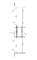
以下、図面について本発明の実施形態を詳細に説明する。図1は本発明の地下構造物の施工法の函体の推進前の要部の縦断側面図、図2は同上函体の推進後の要部の縦断側面図である。また、図3〜図8は各工程の縦断側面図である。 Hereinafter, embodiments of the present invention will be described in detail with reference to the drawings. FIG. 1 is a longitudinal sectional side view of the main part of the construction method of the underground structure of the present invention before promotion of the box, and FIG. 2 is a longitudinal side view of the main part after promotion of the same box. Moreover, FIGS. 3-8 is a vertical side view of each process.
また、図3〜図8は各工程の縦断側面図で、図3に示すように鉄道などの上部交通(図示は省略した)の脇に土留鋼矢板2からなる仮土留杭を打設して発進坑3と到達坑4を築造し、この発進坑3と到達坑4間に渡るようにフリクションカッタープレート7を二重にして配設する。
3 to 8 are vertical side views of each process, and as shown in FIG. 3, a temporary earth retaining pile consisting of earth retaining
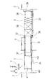
かかる二重にしたフリクションカッタープレート7は圧入または牽引により地中に埋設するが、このうち牽引の場合は図12に示すように、地盤切削ワイヤ27による地盤切削機28で地盤を切削して、牽引装置29で到達坑4側から引き込む。フリクションカッタープレート7は発進坑3側で順次溶接によりつないでいく。
The doubled
前記二重にしたフリクションカッタープレート7は図10、図11に示すように推進させようとするコンクリート函体9の外形に対応するように下部、側部及び上部の四辺矩形配列に組み配置し、その際、土留鋼矢板2は鏡開きされ、フリクションカッタープレート7で囲まれた内方の鋼矢板を土留め材40とする。
The double-sided
外側に位置するフリクションカッタープレート7は図4および図9に示すように固定装置32としてその端部にH形鉄による桁材30を渡し、リブ材31により溶接固定する。
As shown in FIGS. 4 and 9, the
発進坑3と到達坑4とにはそれぞれ発進台33と到達台34をコンクリート床盤で形成し、また、発進坑3には反力壁35を設ける。
The
前記外側に位置するフリクションカッタープレート7で下部に位置するものは、アンカー36により発進台33に固定してもよい。
The lower portion of the
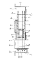
図5に示すように発進坑3にコンクリート函体9とその前に鋼材で枠組みした押角37を配置する。
As shown in FIG. 5, a
二重にしたフリクションカッタープレート7のうち内側のフリクションカッタープレート7の端部はこの押角37に重合させる。押角37は後方の鋼材を前方の鋼材よりも高くして段差を設け、この段差部でフリクションカッタープレート7の端部を係止できるようにする。
The end of the
図6に示すように、反力壁35とコンクリート函体9の間に元押しジャッキ38およびストラット39をセットし、元押しジャッキ38によりコンクリート函体9を押し出すが、同時に押角37およびフリクションカッタープレート7とその内部の土砂41も押し出す。
As shown in FIG. 6, the
二重にしたフリクションカッタープレート7のうち外側のフリクションカッタープレート7は内側のフリクションカッタープレート7に対して摩擦低減の縁切り材として作用し、内側のフリクションカッタープレート7は内部の土砂41の土留め材として作用する。また、土砂41の前後は土留め材40で押さえられる。
Of the double-sided
このようにして図7に示すように、到達坑4に出たフリクションカッタープレート7および土砂41、押角37は適宜撤去し、図8に示すようにコンクリート函体9の先端が到達坑4に達したならば施工を完了する。
Thus, as shown in FIG. 7, the
2 土留鋼矢板
3 発進坑 4 到達坑
5 推進機 6 箱型ルーフ
6a,6b 鉤状の継手 7 フリクションカッタープレート
8 反力壁 9 コンクリート函体
10 元押しジャッキ 11 刃口
12 小ジャッキ 13 支持材
14 止め部材 15 受台
16 ストラット 17 腹起こし材
18 タイロット材 19 土留部材
20 発進台 21 反力体
22 反力杭 23 反力壁
24 牽引ジャッキ 25 牽引ケーブル
26 定着装置 27 地盤切削ワイヤ
28 地盤切削機 29 牽引装置
30 桁材 31 リブ材
32 固定装置 33 発進台
34 到達台 35 反力壁
36 アンカー 37 押角
38 元押しジャッキ 39 ストラット
40 土留め材 41 土砂
DESCRIPTION OF
Claims (2)
Friction knife plate is positioned to span between arrival anti the starting pit constructed by pouring a temporary earth retaining pile consisting of earth retaining sheet pile, the interior of the steel sheet piles in friction cutter plate inside the sediment was Kagamibiraki the earth retaining sheet piles The construction method of the underground structure of Claim 1 which arrange | positions back and forth as earth retaining material.
Priority Applications (1)
| Application Number | Priority Date | Filing Date | Title |
|---|---|---|---|
| JP2016009703A JP6510432B2 (en) | 2016-01-21 | 2016-01-21 | Construction method of underground structure |
Applications Claiming Priority (1)
| Application Number | Priority Date | Filing Date | Title |
|---|---|---|---|
| JP2016009703A JP6510432B2 (en) | 2016-01-21 | 2016-01-21 | Construction method of underground structure |
Publications (2)
| Publication Number | Publication Date |
|---|---|
| JP2017128944A JP2017128944A (en) | 2017-07-27 |
| JP6510432B2 true JP6510432B2 (en) | 2019-05-08 |
Family
ID=59394508
Family Applications (1)
| Application Number | Title | Priority Date | Filing Date |
|---|---|---|---|
| JP2016009703A Active JP6510432B2 (en) | 2016-01-21 | 2016-01-21 | Construction method of underground structure |
Country Status (1)
| Country | Link |
|---|---|
| JP (1) | JP6510432B2 (en) |
Cited By (1)
| Publication number | Priority date | Publication date | Assignee | Title |
|---|---|---|---|---|
| CN109931071A (en) * | 2019-04-22 | 2019-06-25 | 合肥世忠科技开发有限公司 | A kind of minor diameter compression concrete side wall machine |
Family Cites Families (4)
| Publication number | Priority date | Publication date | Assignee | Title |
|---|---|---|---|---|
| JP4317843B2 (en) * | 2005-12-01 | 2009-08-19 | 植村技研工業株式会社 | Construction method for underground structures |
| WO2008090623A1 (en) * | 2007-01-26 | 2008-07-31 | Kawasaki Jukogyo Kabushiki Kaisha | Shield machine |
| JP5300368B2 (en) * | 2008-08-12 | 2013-09-25 | 東日本旅客鉄道株式会社 | Underground structure construction method |
| JP5781574B2 (en) * | 2013-09-03 | 2015-09-24 | 植村 誠 | Starting reaction device for open shield machine |
-
2016
- 2016-01-21 JP JP2016009703A patent/JP6510432B2/en active Active
Cited By (1)
| Publication number | Priority date | Publication date | Assignee | Title |
|---|---|---|---|---|
| CN109931071A (en) * | 2019-04-22 | 2019-06-25 | 合肥世忠科技开发有限公司 | A kind of minor diameter compression concrete side wall machine |
Also Published As
| Publication number | Publication date |
|---|---|
| JP2017128944A (en) | 2017-07-27 |
Similar Documents
| Publication | Publication Date | Title |
|---|---|---|
| JP4317843B2 (en) | Construction method for underground structures | |
| JP2008223397A (en) | Construction method for underground structure | |
| JP6510432B2 (en) | Construction method of underground structure | |
| JP5885229B2 (en) | Reaction force device | |
| CN108729469B (en) | Construction method of underground structure | |
| JP6510620B1 (en) | Construction method of underground structure and push-in jack used therefor | |
| JP6113778B2 (en) | Construction method for underground structures | |
| JP4134089B2 (en) | Construction method for underground structures | |
| JP7177233B2 (en) | Start Reaction Force Structure and Method for Concrete Box or Open Shield Machine | |
| JP6434372B2 (en) | Removal method of existing structures | |
| JP3887383B2 (en) | Construction method for underground structures | |
| JP6714060B2 (en) | Construction method of underground structure | |
| JP6212087B2 (en) | Construction method for underground structures | |
| JP6542825B2 (en) | Construction method of underground structure | |
| JP6445478B2 (en) | Construction method for underground structures | |
| JP6510690B1 (en) | Construction method of underground structure | |
| JP5054164B2 (en) | Construction method for underground structures | |
| JP6441871B2 (en) | Box roof deflection reduction method for box roof method | |
| JP6139613B2 (en) | Construction method for underground structures | |
| JP3116098B2 (en) | Construction method for underground structures | |
| JP2876435B2 (en) | How to build underground structures | |
| JP5976728B2 (en) | Widening method for existing structures | |
| JP5394454B2 (en) | Open shield method | |
| JP6908666B2 (en) | Construction method of underground structure | |
| JP5999792B2 (en) | Construction method of reaction force device |
Legal Events
| Date | Code | Title | Description |
|---|---|---|---|
| A621 | Written request for application examination |
Free format text: JAPANESE INTERMEDIATE CODE: A621 Effective date: 20180403 |
|
| A977 | Report on retrieval |
Free format text: JAPANESE INTERMEDIATE CODE: A971007 Effective date: 20181114 |
|
| A131 | Notification of reasons for refusal |
Free format text: JAPANESE INTERMEDIATE CODE: A131 Effective date: 20181218 |
|
| A521 | Request for written amendment filed |
Free format text: JAPANESE INTERMEDIATE CODE: A523 Effective date: 20190214 |
|
| TRDD | Decision of grant or rejection written | ||
| A01 | Written decision to grant a patent or to grant a registration (utility model) |
Free format text: JAPANESE INTERMEDIATE CODE: A01 Effective date: 20190402 |
|
| A61 | First payment of annual fees (during grant procedure) |
Free format text: JAPANESE INTERMEDIATE CODE: A61 Effective date: 20190404 |
|
| R150 | Certificate of patent or registration of utility model |
Ref document number: 6510432 Country of ref document: JP Free format text: JAPANESE INTERMEDIATE CODE: R150 |
|
| R250 | Receipt of annual fees |
Free format text: JAPANESE INTERMEDIATE CODE: R250 |
|
| R250 | Receipt of annual fees |
Free format text: JAPANESE INTERMEDIATE CODE: R250 |
|
| R250 | Receipt of annual fees |
Free format text: JAPANESE INTERMEDIATE CODE: R250 |