JP6125766B2 - Manufacturing method and manufacturing apparatus for battery and buffer member - Google Patents
Manufacturing method and manufacturing apparatus for battery and buffer member Download PDFInfo
- Publication number
- JP6125766B2 JP6125766B2 JP2012139548A JP2012139548A JP6125766B2 JP 6125766 B2 JP6125766 B2 JP 6125766B2 JP 2012139548 A JP2012139548 A JP 2012139548A JP 2012139548 A JP2012139548 A JP 2012139548A JP 6125766 B2 JP6125766 B2 JP 6125766B2
- Authority
- JP
- Japan
- Prior art keywords
- current collector
- electrode current
- buffer member
- positive electrode
- negative electrode
- Prior art date
- Legal status (The legal status is an assumption and is not a legal conclusion. Google has not performed a legal analysis and makes no representation as to the accuracy of the status listed.)
- Active
Links
- 238000004519 manufacturing process Methods 0.000 title claims description 39
- 239000006262 metallic foam Substances 0.000 claims description 30
- 238000005096 rolling process Methods 0.000 claims description 21
- 238000000034 method Methods 0.000 claims description 13
- 239000000463 material Substances 0.000 claims description 11
- 230000002093 peripheral effect Effects 0.000 claims description 11
- 239000004033 plastic Substances 0.000 claims description 8
- 229910052751 metal Inorganic materials 0.000 description 74
- 239000002184 metal Substances 0.000 description 74
- PXHVJJICTQNCMI-UHFFFAOYSA-N nickel Substances [Ni] PXHVJJICTQNCMI-UHFFFAOYSA-N 0.000 description 47
- 229910052759 nickel Inorganic materials 0.000 description 19
- 239000006260 foam Substances 0.000 description 16
- 239000011347 resin Substances 0.000 description 13
- 229920005989 resin Polymers 0.000 description 13
- 230000004048 modification Effects 0.000 description 8
- 238000012986 modification Methods 0.000 description 8
- 238000003466 welding Methods 0.000 description 6
- 229910000831 Steel Inorganic materials 0.000 description 5
- 239000006096 absorbing agent Substances 0.000 description 5
- 230000035939 shock Effects 0.000 description 5
- 239000010959 steel Substances 0.000 description 5
- 239000011800 void material Substances 0.000 description 5
- 230000008602 contraction Effects 0.000 description 4
- 238000007599 discharging Methods 0.000 description 4
- 238000010248 power generation Methods 0.000 description 4
- 238000003825 pressing Methods 0.000 description 4
- -1 Nickel metal hydride Chemical class 0.000 description 3
- 238000010586 diagram Methods 0.000 description 3
- 239000008151 electrolyte solution Substances 0.000 description 3
- HBBGRARXTFLTSG-UHFFFAOYSA-N Lithium ion Chemical compound [Li+] HBBGRARXTFLTSG-UHFFFAOYSA-N 0.000 description 2
- 239000004020 conductor Substances 0.000 description 2
- 238000006073 displacement reaction Methods 0.000 description 2
- 229910001416 lithium ion Inorganic materials 0.000 description 2
- 229910052987 metal hydride Inorganic materials 0.000 description 2
- 238000000465 moulding Methods 0.000 description 2
- UFHFLCQGNIYNRP-UHFFFAOYSA-N Hydrogen Chemical compound [H][H] UFHFLCQGNIYNRP-UHFFFAOYSA-N 0.000 description 1
- 239000004743 Polypropylene Substances 0.000 description 1
- KWYUFKZDYYNOTN-UHFFFAOYSA-M Potassium hydroxide Chemical compound [OH-].[K+] KWYUFKZDYYNOTN-UHFFFAOYSA-M 0.000 description 1
- 238000007792 addition Methods 0.000 description 1
- 229910045601 alloy Inorganic materials 0.000 description 1
- 239000000956 alloy Substances 0.000 description 1
- 230000003139 buffering effect Effects 0.000 description 1
- 230000037430 deletion Effects 0.000 description 1
- 238000012217 deletion Methods 0.000 description 1
- 230000006866 deterioration Effects 0.000 description 1
- 239000000428 dust Substances 0.000 description 1
- 230000005611 electricity Effects 0.000 description 1
- 239000003792 electrolyte Substances 0.000 description 1
- 238000010894 electron beam technology Methods 0.000 description 1
- 230000002349 favourable effect Effects 0.000 description 1
- 229910052739 hydrogen Inorganic materials 0.000 description 1
- 239000001257 hydrogen Substances 0.000 description 1
- 239000011810 insulating material Substances 0.000 description 1
- 150000002500 ions Chemical class 0.000 description 1
- 238000010030 laminating Methods 0.000 description 1
- 239000007773 negative electrode material Substances 0.000 description 1
- 229910000652 nickel hydride Inorganic materials 0.000 description 1
- BFDHFSHZJLFAMC-UHFFFAOYSA-L nickel(ii) hydroxide Chemical compound [OH-].[OH-].[Ni+2] BFDHFSHZJLFAMC-UHFFFAOYSA-L 0.000 description 1
- 239000004745 nonwoven fabric Substances 0.000 description 1
- 229920001155 polypropylene Polymers 0.000 description 1
- 239000007774 positive electrode material Substances 0.000 description 1
- 238000007493 shaping process Methods 0.000 description 1
- 238000003860 storage Methods 0.000 description 1
- 239000002699 waste material Substances 0.000 description 1
- 238000004804 winding Methods 0.000 description 1
Images


Classifications
-
- Y—GENERAL TAGGING OF NEW TECHNOLOGICAL DEVELOPMENTS; GENERAL TAGGING OF CROSS-SECTIONAL TECHNOLOGIES SPANNING OVER SEVERAL SECTIONS OF THE IPC; TECHNICAL SUBJECTS COVERED BY FORMER USPC CROSS-REFERENCE ART COLLECTIONS [XRACs] AND DIGESTS
- Y02—TECHNOLOGIES OR APPLICATIONS FOR MITIGATION OR ADAPTATION AGAINST CLIMATE CHANGE
- Y02E—REDUCTION OF GREENHOUSE GAS [GHG] EMISSIONS, RELATED TO ENERGY GENERATION, TRANSMISSION OR DISTRIBUTION
- Y02E60/00—Enabling technologies; Technologies with a potential or indirect contribution to GHG emissions mitigation
- Y02E60/10—Energy storage using batteries
-
- Y—GENERAL TAGGING OF NEW TECHNOLOGICAL DEVELOPMENTS; GENERAL TAGGING OF CROSS-SECTIONAL TECHNOLOGIES SPANNING OVER SEVERAL SECTIONS OF THE IPC; TECHNICAL SUBJECTS COVERED BY FORMER USPC CROSS-REFERENCE ART COLLECTIONS [XRACs] AND DIGESTS
- Y02—TECHNOLOGIES OR APPLICATIONS FOR MITIGATION OR ADAPTATION AGAINST CLIMATE CHANGE
- Y02P—CLIMATE CHANGE MITIGATION TECHNOLOGIES IN THE PRODUCTION OR PROCESSING OF GOODS
- Y02P70/00—Climate change mitigation technologies in the production process for final industrial or consumer products
- Y02P70/50—Manufacturing or production processes characterised by the final manufactured product
Landscapes
- Cell Electrode Carriers And Collectors (AREA)
- Secondary Cells (AREA)
- Connection Of Batteries Or Terminals (AREA)
Description
本発明は、電池とその緩衝部材の製造方法および製造装置に関する。 The present invention relates to a manufacturing method and a manufacturing apparatus for a battery and its buffer member.
従来、携帯電話やモバイルPC、電動工具、電動自転車など、さまざまな製品に電池が用いられている。近年では、風力発電や太陽光発電などの自然エネルギーを利用した発電にも電池が使われている。これは不安定な出力を電池で補い、出力を平滑化するために用いられるもので、大容量の電池が使われている。その他、大容量の電池は、ハイブリッド車や電気自動車、電車などの車両に搭載されることが知られている。 Conventionally, batteries are used in various products such as mobile phones, mobile PCs, electric tools, and electric bicycles. In recent years, batteries are also used for power generation using natural energy such as wind power generation and solar power generation. This is used to compensate for unstable output with a battery and smooth the output, and a large capacity battery is used. In addition, it is known that large-capacity batteries are mounted on vehicles such as hybrid cars, electric cars, and trains.
このような車両に搭載する大容量の電池には、高出力、高エネルギー密度、電圧安定性などの面から、ニッケル水素電池やリチウムイオン電池が広く採用されている。 Nickel metal hydride batteries and lithium ion batteries are widely used for such high-capacity batteries mounted on vehicles in terms of high output, high energy density, and voltage stability.
従来のニッケル水素電池やリチウムイオン電池の構造として、例えば捲回型電池や角形電池がある。捲回型電池は、シート状の正極および負極をシート状のセパレータを介して捲回することにより電極体を構成し、電極体を電解液と共に電池容器内に収容してなる。また、角形電池は、複数の正極と負極とをセパレータを介して交互に積層することにより電極体を構成し、電極体を電解液と共に電池容器内に収容してなる。いずれの電池も、正極と負極とが、それぞれ正極集電体と負極集電体とに接続され、電気を取り出す。 As a structure of a conventional nickel metal hydride battery or lithium ion battery, for example, there are a wound battery and a square battery. A wound battery comprises an electrode body formed by winding a sheet-like positive electrode and a negative electrode through a sheet-like separator, and the electrode body is housed in a battery container together with an electrolytic solution. In addition, the rectangular battery is configured by forming an electrode body by alternately laminating a plurality of positive electrodes and negative electrodes via separators, and accommodating the electrode body together with an electrolytic solution in a battery container. In any battery, the positive electrode and the negative electrode are connected to the positive electrode current collector and the negative electrode current collector, respectively, and electricity is taken out.
このような角形電池として、例えば、板状の正極および負極がプリーツ状のセパレータを介して電極体を構成する構造が提案されている(例えば、特許文献1参照)。 As such a rectangular battery, for example, a structure in which a plate-like positive electrode and a negative electrode constitute an electrode body via a pleated separator has been proposed (see, for example, Patent Document 1).
特許文献1の発明によれば、対向配置された正極集電板と負極集電板との間に、プリーツ状のセパレータを介して多数の正極および負極が交互に対向して積層されており、正極、負極の端面を、正極集電板、負極集電板にそれぞれ接触させることによって、これらの導通を確保している。 According to the invention of Patent Document 1, a large number of positive electrodes and negative electrodes are alternately opposed and stacked via a pleated separator between a positive electrode current collector plate and a negative electrode current collector plate arranged to face each other. The end faces of the positive electrode and the negative electrode are brought into contact with the positive electrode current collector plate and the negative electrode current collector plate, respectively, to ensure conduction between them.
ところで、電池は充放電によって正極と負極とが膨張収縮を繰り返す。この正極および負極の膨張収縮によって、正極と正極集電体、負極と負極集電体の間にずれが生じる場合がある。ずれが生じてこれらの接触が十分でなくなると、接触抵抗が増大するなど電池容量の低下や電池性能の低下を招くおそれがある。これを回避するためには、正極と正極集電体、負極と負極集電体とが接触した状態を維持する必要がある。 By the way, as for a battery, a positive electrode and a negative electrode repeat expansion and contraction by charging / discharging. Due to the expansion and contraction of the positive electrode and the negative electrode, a displacement may occur between the positive electrode and the positive electrode current collector, or between the negative electrode and the negative electrode current collector. If the displacement occurs and these contacts become insufficient, there is a risk that the battery capacity may be lowered and the battery performance may be lowered, such as an increase in contact resistance. In order to avoid this, it is necessary to maintain a state where the positive electrode and the positive electrode current collector, and the negative electrode and the negative electrode current collector are in contact with each other.
また、特許文献2の発明では、電子ビーム溶接法により、積層した各電極板の端面を直接集電体に溶接する方法が提案されている。すなわち、各電極板をそれぞれ集電体の表面に対して直立するような姿勢で突き合わせて接合する方法であり、このとき集電体と電極板はT型継手を構成する。(特許文献2の第1図(d)、第2図(b)参照)。
Further, in the invention of
また、特許文献3の発明では、互いに対向配置された平板状の正極集電体および負極集電体と、両集電体の間でこれらの対向方向Xに直交する方向に、セパレータを介して対向して交互に積層された複数の正極および負極からなる電極体と、両集電体と電極体との間、にそれぞれ介在するシート状の緩衝部材とを備える積層型電池が提案されている(特許文献3の第3図参照)。
Further, in the invention of
しかしながら、特許文献1の発明では、正極や負極の寸法にばらつきがある場合や、電池の充放電によって正極や負極が膨張収縮した場合など、一部の正極や負極が、正極集電体や負極集電体に接触しない状態となるおそれがある。この場合、正極集電体や負極集電体に接触しない正極や負極が、電池の充放電容量にまったく寄与しないこととなり、設計どおりのエネルギー容量が得られない。また、接触はしていても、接触圧が不十分であれば、十分な充放電性能が得られない場合がある。 However, in the invention of Patent Document 1, some of the positive electrodes and the negative electrodes are positive current collectors and negative electrodes, such as when the dimensions of the positive electrodes and negative electrodes vary, or when the positive electrodes and negative electrodes expand and contract due to charging and discharging of the battery. There is a risk of not being in contact with the current collector. In this case, the positive electrode and the negative electrode that are not in contact with the positive electrode current collector and the negative electrode current collector do not contribute to the charge / discharge capacity of the battery at all, and the designed energy capacity cannot be obtained. Even if the contact is made, if the contact pressure is insufficient, sufficient charge / discharge performance may not be obtained.
また、特許文献2の発明のように、正極および負極を、正極集電体および負極集電体に溶接することにより接触を確保する場合、溶接屑が電池内に残留し、内部短絡のような不具合の原因となるほか、電極の溶接加工、溶接位置の調整などが煩雑で量産性においても問題がある。
Also, as in the invention of
また、特許文献3の発明のように、電極体と正極集電体および負極集電体との間に緩衝部材を配することは、これらの導通を確保する上で有用である。しかし、この緩衝部材は、塑性変形可能な導電素材からなる緩衝シート部と、平滑な主面を有する導電素材からなる接触シート部とを互いに重ねて成形している。すなわち、この緩衝部材を成形するにあたり、2つの異なる部材をそれぞれ成形する工程が必要となる。
Further, as in the invention of
本発明の目的の一つは、これらの課題を解決すべく、電極体と正極集電体および負極集電体との導通を維持して、電池性能の低下を抑制した電池を提供することにある。もう一つの目的は、その電池に用いる緩衝部材の製造方法および製造装置を提供することにある。 In order to solve these problems, one of the objects of the present invention is to provide a battery that maintains the electrical connection between the electrode body, the positive electrode current collector, and the negative electrode current collector, and suppresses deterioration in battery performance. is there. Another object is to provide a manufacturing method and a manufacturing apparatus for a buffer member used in the battery.
上記の目的を達成するため、本発明に係る電池は、互いに対向して配置された正極集電体および負極集電体と、前記正極集電体と前記負極集電体との間に配され、両集電体の対向方向に直交する方向に、セパレータを介して正極と負極とが重ね合わされてなる電極体と、前記正極集電体および前記負極集電体と前記電極体との間の少なくとも一方に介在する緩衝部材と、を備え、
前記緩衝部材は、前記電極体と接する平滑面を具備する第一層と、塑性変形可能な第二層とを有する1枚の多孔金属シートからなることを特徴とする。
In order to achieve the above object, a battery according to the present invention is disposed between a positive electrode current collector and a negative electrode current collector that are arranged to face each other, and between the positive electrode current collector and the negative electrode current collector. An electrode body in which a positive electrode and a negative electrode are superimposed via a separator in a direction perpendicular to the opposing direction of both current collectors, and between the positive electrode current collector and the negative electrode current collector and the electrode body A buffer member interposed in at least one of the above,
The cushioning member includes a first layer having a smooth surface in contact with the electrode body, characterized in that it consists of a single perforated metal sheet having a plastically deformable second layer.
この構成によれば、緩衝部材を電極体と集電体との間に配することにより、電極体と集電体とを確実に接触させ、かつ、これらの接触圧のばらつきを緩衝部材の塑性変形によって吸収する。これにより、集電体と正極または負極とが確実に接触し、また、良好な接触状態を維持する。すなわち、集電体と正極または負極とのずれ等による接触抵抗の増大を抑え、電池性能の低下を抑制する。また、緩衝部材の電極体に接する面が平滑に形成されているので、例えば緩衝部材のバリなどの突起物がセパレータを貫通することによって生じうる内部短絡を防止する。ここで、「平滑面」とは、凹凸が少なく滑らかな平面をいう。 According to this configuration, by arranging the buffer member between the electrode body and the current collector, the electrode body and the current collector can be reliably brought into contact with each other, and variations in the contact pressure can be reduced. Absorbs by deformation. Thereby, a collector and a positive electrode or a negative electrode contact reliably, and a favorable contact state is maintained. That is, an increase in contact resistance due to a shift between the current collector and the positive electrode or the negative electrode is suppressed, and a decrease in battery performance is suppressed. Moreover, since the surface which contacts the electrode body of a buffer member is formed smoothly, the internal short circuit which may arise when protrusions, such as a burr | flash of a buffer member penetrate a separator, for example is prevented. Here, the “smooth surface” refers to a smooth surface with few irregularities.
また、緩衝部材は、平滑面を具備する第一層と塑性変形可能な第二層とが不離一体の一枚の多孔金属シートからなるため、別体の平滑シートと緩衝シートとを重ねた緩衝部材に比べて製造の手間が省ける。なお、緩衝部材は、電極体と正極集電体および負極集電体のいずれか一方に設けてもよいし、双方に設けてもよい。 Further, since the buffer member is formed of a single porous metal sheet in which the first layer having a smooth surface and the second layer capable of plastic deformation are inseparably integrated, the buffer is formed by stacking separate smooth sheets and buffer sheets. Compared to the parts, manufacturing effort can be saved. In addition, a buffer member may be provided in any one of an electrode body, a positive electrode collector, and a negative electrode collector, and may be provided in both.
本発明に係る電池は、前記緩衝部材が、前記第二層の空隙率が前記第一層の空隙率よりも高いことを特徴とする。ここで、「空隙率」とは総体積に占める空隙部分の割合をいい、空隙率が高いほど空隙部分が多くなる。すなわち、第一層に比べて第二層は空隙部分が多くクッション性が高いので、主に第二層が緩衝部として機能する。 Battery according to the present invention, the buffering member, you characterized the porosity of the second layer is higher than the porosity of said first layer. Here, the “void ratio” means the ratio of the void portion in the total volume, and the void portion increases as the void ratio increases. That is, since the second layer has more void portions and higher cushioning properties than the first layer, the second layer mainly functions as a buffer portion.
また、緩衝部材は、例えば第一層の空隙率を29〜51%とし、第二層の空隙率を92〜98%としてもよく、また第一層の空隙率を31〜32%とし、第二層の空隙率を94〜95%としてもよい。また、前記した1枚の多孔金属シートからなる緩衝部材は、多孔金属シートをロールプレス等により圧延して製造することが一般的である。 The buffer member may have, for example, a porosity of the first layer of 29 to 51%, a porosity of the second layer of 92 to 98%, a porosity of the first layer of 31 to 32%, The porosity of the two layers may be 94 to 95%. Also, the buffer member made from a single perforated metal sheet mentioned above, it is Ru general der to produce a porous metal sheet is rolled by a roll press or the like.
本発明に係る緩衝部材の製造方法は、互いに対向して配置された正極集電体および負極集電体と、前記正極集電体と前記負極集電体との間に配され、両集電体の対向方向に直交する方向に、セパレータを介して正極と負極とが重ね合わされてなる電極体と、前記正極集電体および前記負極集電体と前記電極体との間の少なくとも一方に介在する緩衝部材と、を備えた電池における緩衝部材の製造方法であって、
1枚の金属フォームを2つのロールにより、前記金属フォームの一方のロールに接する面をしごきつつ圧延する工程を含み、平滑面を具備する第一層と、塑性変形可能な第二層とを有する緩衝部材を成形する工程を備えることを特徴とする。
The buffer member manufacturing method according to the present invention includes a positive electrode current collector and a negative electrode current collector that are disposed to face each other, and are disposed between the positive electrode current collector and the negative electrode current collector. Interposed in at least one of the positive electrode current collector and the negative electrode current collector and the electrode body, in which the positive electrode and the negative electrode are overlapped via a separator in a direction perpendicular to the opposing direction of the body And a buffer member manufacturing method for a battery comprising:
The method includes a step of rolling one metal foam with two rolls while squeezing a surface in contact with one roll of the metal foam, and includes a first layer having a smooth surface and a second layer capable of plastic deformation. it further comprising a step of forming a buffer member.
この構成によれば、1枚の金属フォームを2つのロールにより圧延して、平滑面を具備する第一層と、塑性変形可能な第二層とを有する緩衝部材を容易に製造することができる。ここで、2つのロールにより圧延するとは、例えば2つのロールを含み複数のロールを備えたロールプレスによって圧延することや、2つのロールにより圧延すること、別体のロールにより圧延すること、ロールプレス機によりプレスすることなどを含む。 According to this configuration, one metal foam can be rolled with two rolls to easily manufacture a buffer member having a first layer having a smooth surface and a second layer that can be plastically deformed. . Here, rolling with two rolls means, for example, rolling with a roll press including two rolls and a plurality of rolls, rolling with two rolls, rolling with separate rolls, roll press Including pressing by a machine.
また、1枚の金属フォームを2つのロールにより圧延するとき、金属フォームの一方の面をしごきつつ圧延することで、金属フォームのしごかれる面側の第一層と、他方の面側の第二層とで、面の状態や空隙率の違いなど異なる性質の第一層と第二層とを形成できる。なお、しごかれる側の面が平滑な面となり、空隙率も小さくなる。また、一方の面をしごきつつ圧延することで、圧延後の金属フォームは反り返った状態で送り出されることがあり、その場合には、例えば、さらに別のロールによって圧延したり、プレス機によってプレスするなどして反りを戻す。 In addition, when rolling one metal foam with two rolls, by rolling one side of the metal foam while squeezing, the first layer on the side where the metal foam is squeezed and the first layer on the other side With the two layers, the first layer and the second layer having different properties such as the surface state and the difference in porosity can be formed. In addition, the surface on the side to be squeezed becomes a smooth surface, and the porosity is also reduced. In addition, by rolling while squeezing one side, the rolled metal foam may be sent out in a warped state. In that case, for example, it is rolled by another roll or pressed by a press machine. To return the warp.
本発明に係る緩衝部材の製造方法は、前記2つのロールが、径の異なるロールであってもよい。この構成によれば、径の異なるロールで1枚の金属フォームを圧延することにより、ロール同士の回転速度を異なるものとしてロール間に周速の差を発生しやすくする。発生した周速の差によって金属フォームは一方の面がしごかれることとなり、性質の異なる第一層と第二層とが形成された1枚の多孔金属シートとできる。 Method for producing a cushioning member according to the present invention, the two rolls, but it may also be a different roll diameters. According to this configuration, by rolling a single metal foam with rolls having different diameters, the rotational speed between the rolls is made different so that a difference in peripheral speed is easily generated between the rolls. Due to the difference in the generated peripheral speed, one surface of the metal foam is rubbed, and a single porous metal sheet in which a first layer and a second layer having different properties are formed can be obtained.
本発明に係る緩衝部材の製造方法は、前記2つのロールが、材質の異なるロールであってもよい。この構成によれば、材質の異なるロールで1枚の金属フォームを圧延することにより、より送りやすいロールの主導によって金属フォームを送らせることとなる。もう一方のロールと金属フォームとの間はロールの周速と金属フォームの送り速度が異なって金属フォームは一方の面がしごかれることとなり、性質の異なる第一層と第二層とが形成された1枚の多孔金属シートとできる。ここで、材質の異なるロールとは、例えば、一方のロールを樹脂とし、他方のロールを金属としたり、一方のロールと他方のロールとで異なる種類の金属のロールとしたりなどとすればよい。 Method for producing a cushioning member according to the present invention, the two rolls, but it may also be rolls of different materials. According to this configuration, by rolling a single metal foam with rolls of different materials, the metal foam can be fed by the initiative of a roll that is easier to feed. Between the other roll and the metal foam, the peripheral speed of the roll and the feed speed of the metal foam are different, and one side of the metal foam will be rubbed, forming the first and second layers with different properties One porous metal sheet formed can be obtained. Here, the rolls of different materials may be, for example, one of the rolls made of resin and the other roll made of metal, or one roll and the other roll made of different kinds of metal.
本発明に係る緩衝部材の製造方法は、前記2つのロールが、周速の異なるロールであってもよい。この構成によれば、2つのロールの周速を変えて、1枚の金属フォームを圧延することにより、性質の異なる第一層と第二層とが形成された1枚の多孔金属シートとできる。ここで、周速の異なるとは、例えば、一方を樹脂の大ロールでゆっくりと回転し、他方を金属の小ロールで高速回転させる。 Method for producing a cushioning member according to the present invention, the two rolls, but it may also be rolls of different peripheral speeds. According to this configuration, a single porous metal sheet in which the first layer and the second layer having different properties are formed can be obtained by rolling one metal foam while changing the peripheral speed of the two rolls. . Here, the difference in peripheral speed means, for example, that one is slowly rotated with a large roll of resin and the other is rotated at a high speed with a small roll of metal.
本発明に係る緩衝部材の製造方法は、前記2つのロールが、一方のロールが駆動ロールであり、他方のロールが固定ロールであってもよい。この構成によれば、駆動ロールと固定ロールとで1枚の金属フォームを圧延することにより、性質の異なる第一層と第二層とが形成された1枚の多孔金属シートとできる。 Method for producing a cushioning member according to the present invention, the two rolls is a one roll is the drive roll, the other roll but it may also be a fixed roll. According to this structure, it can be set as the one porous metal sheet in which the 1st layer and the 2nd layer from which a property differs were formed by rolling one metal foam with a drive roll and a fixed roll.
本発明に係る緩衝部材の製造方法は、前記2つのロールにかえて、1つのロールと、1つの固定バーとにより圧延することとしてもよい。この構成によれば、駆動ロールと固定バーとで1枚の金属フォームを圧延することにより、性質の異なる第一層と第二層とが形成された1枚の多孔金属シートとできる。 Method for producing a cushioning member according to the present invention, instead of the two rolls, one roll, but it may also a be rolled by one of the fixed bar. According to this structure, it can be set as the one porous metal sheet in which the 1st layer and the 2nd layer from which a property differs were formed by rolling one metal foam with a drive roll and a fixed bar.
本発明に係る緩衝部材の製造装置は、互いに対向して配置された正極集電体および負極集電体と、前記正極集電体と前記負極集電体との間に配され、両集電体の対向方向に直交する方向に、セパレータを介して正極と負極とが重ね合わされてなる電極体と、前記正極集電体および前記負極集電体と前記電極体との間の少なくとも一方に介在する緩衝部材と、を備えた電池における緩衝部材の製造装置であって、
1枚の金属フォームを2つのロールにより、前記金属フォームの一方のロールに接する面をしごきつつ圧延する手段を含み、平滑面を具備する第一層と、塑性変形可能な第二層とを有する前記緩衝部材を成形する手段を備えることを特徴とする。
The buffer member manufacturing apparatus according to the present invention includes a positive electrode current collector and a negative electrode current collector that are disposed to face each other, and are disposed between the positive electrode current collector and the negative electrode current collector. Interposed in at least one of the positive electrode current collector and the negative electrode current collector and the electrode body, in which the positive electrode and the negative electrode are overlapped via a separator in a direction perpendicular to the opposing direction of the body A buffer member manufacturing apparatus in a battery comprising:
It includes means for rolling one metal foam with two rolls while squeezing the surface in contact with one roll of the metal foam, and has a first layer having a smooth surface and a second layer capable of plastic deformation. it comprising means for shaping the cushioning member.
この構成によれば、当該製造装置により1枚の金属フォームを圧延することで、平滑面を具備する第一層と、塑性変形可能な第二層とを有する緩衝部材を容易に製造することができる。 According to this configuration, it is possible to easily manufacture a buffer member having a first layer having a smooth surface and a plastically deformable second layer by rolling one metal foam by the manufacturing apparatus. it can.
本発明に係る緩衝部材の製造装置は、前記2つのロールは、径の異なる複数のロール、または材質の異なる複数のロール、または径および材質の異なるロール、または、駆動ロールと固定ロールであることを特徴とする。
In the shock absorber manufacturing apparatus according to the present invention, the two rolls are a plurality of rolls having different diameters, a plurality of rolls having different materials, a roll having different diameters and materials, or a driving roll and a fixed roll. the shall be the feature.
以上のように、本発明は、電極と集電体との間に緩衝部材を介在させることで、電極と集電体との接続を維持して導通を確保する。すなわち、電池の充放電等によって生じうる電極と集電体との位置ずれ等による接触抵抗の増大を抑制し、電池性能の低下を抑える。 As described above, according to the present invention, the buffer member is interposed between the electrode and the current collector, thereby maintaining the connection between the electrode and the current collector to ensure conduction. That is, an increase in contact resistance due to a positional deviation between the electrode and the current collector, which may occur due to charging / discharging of the battery, is suppressed, and a decrease in battery performance is suppressed.
以下、本発明に係る実施形態を図面に基づき説明するが、本発明は下記実施形態に限定されるものではない。 Hereinafter, although the embodiment concerning the present invention is described based on a drawing, the present invention is not limited to the following embodiment.
<第一実施形態>
(1)電池の構造
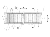
図1に示すように、本実施形態の電池1は、正極3と負極4とセパレータ5とからなる電極体2と、アルカリ系の電解液と共に電極体2を収納する角形セル6とを備える。角形セル6は、絶縁性の矩形の枠形部材7と、枠形部材7の開口を覆うようにZ方向に対向して配置され、周縁部が略直角に折り曲げられた矩形の正極集電体8および負極集電体9とを備える。
<First embodiment>
(1) Battery Structure As shown in FIG. 1, a battery 1 according to this embodiment includes an
図2に示すように、本実施形態の電極体2は、一例として、複数の短冊状の正極3と複数の短冊状の負極4とが、プリーツ状に折り曲げられたセパレータ5を介し、正極集電体8と負極集電体9とが対向する方向Zと直交する方向Xに、交互に積層された構造を有する。そして、電極体2は角形セル6に収納され、正極3と正極集電体8、負極4と負極集電体9が緩衝部材10を介して電気的に接続されている。
As shown in FIG. 2, the
なお、一例として、正極3は水酸化ニッケルを主な正極活物質とし、負極4は水素吸蔵合金を主な負極活物質とし、セパレータ5は親水性を有するポリプロピレン系の不織布からなる。よって、本実施形態の電池1はニッケル水素二次電池として構成されている。また、電極体2は、セパレータ5がプリーツ状以外の構造であってもよく、例えば、複数の袋状のセパレータに夫々正極と負極とを交互に収納して、これらを積層する構造などとしてもよい。
As an example, the
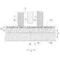
次に、図2、図3を用いて、電極体2と正極集電体8および負極集電体9との接続構造について説明する。図2に示すように、電極体2と正極集電体8および負極集電体9との間には、シート状の緩衝部材10が介在している。なお、本実施形態においては、一例として緩衝部材を電極体2と正極集電体8および負極集電体9との間に配しているが、いずれか一方の間にのみ緩衝部材10を配することもできる。また、以下の説明において、正極集電体8側を中心に説明するが、負極集電体9側も正極集電体8側と同様の構造を有している。
Next, a connection structure between the
図3に示すように、正極3と正極集電体8との間には、導電性を有するシート状の緩衝部材10が介在している。すなわち、正極集電体8の内壁面8aに沿って緩衝部材10が配置されていて、緩衝部材10の電極体2側の第一面11aが正極3の正極集電体8側の端部3aに接触し、第一面11aとは反対側の第二面12aが正極集電体8の内壁面8aに接触している。これにより、正極3と正極集電体8とが緩衝部材10を介して電気的に接続される。
As shown in FIG. 3, a conductive sheet-
また、プリーツ状のセパレータ5の折り曲げ部5aは、緩衝部材10と接する、若しくは、緩衝部材10と近接している。このとき、緩衝部材10の第一面11aが平滑面として形成されているので、セパレータ5が緩衝部材10のバリ等の突起によって突き破られ内部短絡が発生することが防止される。
The
また、正極集電体8側と同様に、負極集電体9の内壁面9aに沿って導電性を有するシート状の緩衝部材10が配置されていて、緩衝部材10の電極体2側の第一面11aが負極4の負極集電体9側の端部4aに接触し、第一面11aとは反対側の第二面12aが負極集電体9の内壁面9aに接触している。これにより、負極4と負極集電体9とが緩衝部材10を介して電気的に接続されている。
Similarly to the positive electrode
なお、本実施形態の電池1では、正極3、負極4、緩衝部材10、正極集電体8、負極集電体9の導通は、金属屑のような異物の混入の防止および工程の簡略化のために溶接は行わず、両集電体8、9の対向方向Zの接触圧(押し付け)によって確保されている。すなわち、正極3と負極4とは、それぞれ正極集電体8と負極集電体9からの内向きの押しつけ力と、セパレータ5の外向きの張力により保持されていて、さらに各緩衝部材10がそれぞれ正極3側と負極4側に付勢して、正極3および負極4と各緩衝部材10とが確実に接触される。
In the battery 1 of the present embodiment, the
これにより、万が一正極3や負極4の寸法にばらつきがある場合や、電池の充放電によって正極3や負極4が膨張収縮した場合などにも、正極3と正極集電体8、負極4と負極集電体9との接触状態を維持する。
As a result, the
(2)緩衝部材10の構造
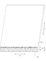
次に、図4に基づき緩衝部材10の構造について説明する。図4に示すように、本実施形態の緩衝部材10は、Z方向に塑性変形可能な1枚の多孔ニッケルシート(多孔金属シート)からなり、平滑な第一面11aを有する第一層11と、第一面11aと反対側の第二面12aを有する第二層12とを備える。そして、第一層11と第二層12とは明確な境界を有さず連続的に繋がっている。
(2) Structure of
また、第二層12は第一層11よりも空隙率が高くなっていて、第二層12が正極3や負極4の膨張収縮等を吸収する緩衝部として機能する。なお、本実施形態では、一例として、第一層11の空隙率が約32%であり、第二層12の空隙率が約95%である。また、第一層11は第一面11aを有し、第一面11aが電極体2と接触する側となる。一方、第二層12は第二面12aを有し、第二面12aが正極集電体8または負極集電体9と接触する側となる。また、第一層11の第一面11aは、平滑面として形成されており、第二層12の第二面12aに比べ、凹凸が少なく滑らかな面である。なお、第二面12aを第一面11aと同じく、平滑面として形成してもよい。
The
上記の通り、本実施形態の緩衝部材10は、電極体2と接触する側の第一面11aが平滑面として形成されているので、電極体2のセパレータ5が緩衝部材10のバリ等の突起によって突き破られ内部短絡が発生することを防止できる。さらに、第一層11と第二層12とが連続的に繋がっているため、第一層11と第二層12とが別体で結合されている場合に比べ、接触抵抗を抑えることができる。
As described above, since the
(3)緩衝部材の製造方法および製造装置
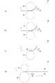
次に、本実施形態の緩衝部材10の製造方法および製造装置について説明する。図5(a)に示すように、緩衝部材10は、厚さ約1.2mmで空隙率約95%の1枚のニッケルフォームFを2つの径の異なる第一の金属ロール31と第二の金属ロール32によって圧延する工程により製造される。第一の金属ロール31と第二の金属ロール32はいずれも金属性のロールであって径が異なる。第一の金属ロール31が径の小さいフリーロールであり、第二の金属ロール32が径の大きい駆動ロールである。すなわち、ニッケルフォームFは、第二の金属ロール32により、第一の金属ロール31側に押しつけられるように圧延される。
(3) Manufacturing Method and Manufacturing Device for Buffer Member Next, a manufacturing method and a manufacturing device for the
このような構成であるため、ニッケルフォームFは、その上面が第一の金属ロール31によりしごかれて、第一の金属ロール31側に反り返るように送り出される(図5(a)参照)。これにより、第一の金属ロール31と接するニッケルフォームFの上面(緩衝部材10の第一の面11a)が平滑な面として形成される。
Since it is such a structure, the nickel form F is sent out so that the upper surface may be squeezed by the
また、このとき、ニッケルフォームFの上面は第一の金属ロール31側に押し当てられてしごかれ、ニッケルフォームFの上面側の層の厚みが約1/3となり、空隙率が約32%となる。これにより、約1.2mmであったニッケルフォームFの厚みが、約0.8mmまで縮められる(図10参照)。
Further, at this time, the upper surface of the nickel form F is pressed against the
なお、本実施形態における第一の金属ロール31と第二の金属ロール32は、一例としてスチールを用いた金属ロールであり、径を250mmと400mmとし、回転速度を4m/分としている。
In addition, the
また、図5(b)に示すように、第一の金属ロール31と第二の金属ロール32により圧延されたニッケルフォームFは反り返ったかたちで送り出されるので、反りを戻すためにロール42と43とを用いる。これにより反りを戻し、緩衝部材10が製造される。以上のように、緩衝部材の製造装置30は、ニッケルフォームFを圧延する第一の金属ロール31と第二の金属ロール32と、ニッケルフォームFの反りを戻すためのロール42と43とを備える。
Further, as shown in FIG. 5B, since the nickel foam F rolled by the
なお、本実施形態では、第一の金属ロール31をフリーロール、第二の金属ロール32を駆動ロールとしているが、第一の金属ロール31と第二の金属ロール32とをともに駆動ロールとしてもよい。この場合、例えば第一の金属ロール31の周速を第二の金属ロール32の周速よりも遅く構成すれば、ニッケルフォームFの送り方向における線速度を、第一の金属ロール31に接する面が第二の金属ロール32に接する面よりも遅くなる。これにより、ニッケルフォームFはその上面が第一の金属ロール31によりしごかれて、ニッケルフォームFの上面を平滑な面として形成できる。
In the present embodiment, the
(変形例1)
次に、緩衝部材の製造装置30の変形例について説明する。図6(a)に示すように、緩衝部材の製造装置33は、金属ロール34と樹脂ロール35とを備える。これらのロールは、材質が異なり、径が同一で、金属ロール34をフリーロールとし、樹脂ロール35を駆動ロールとして構成している。すなわち、ニッケルフォームFは、樹脂ロール35により、金属ロール34側に押しつけられるように圧延される。
(Modification 1)
Next, a modified example of the buffer
このとき、樹脂ロール35は金属ロール34に比べてグリップ力が強いため、ニッケルフォームFは、金属ロール34側に押しつけられ、その上面が金属ロール34によりしごかれて、金属ロール34側に反り返るように送り出される(図6(a)参照)。これにより、金属ロール34と接するニッケルフォームFの上面(緩衝部材10の第一の面11a)が平滑な面として形成される。
At this time, since the
なお、本実施形態における金属ロール34と樹脂ロール35は、一例としてスチールを用いた金属ロールとゴムを用いた樹脂ロールであり、径をスチールロールは150mm、ゴムロールは300mmとし、回転速度を3m/分としている。
The
また、反り返ったニッケルフォームFは、上記同様に、ロール42と43とにより反りを戻す。なお、ロール42と43にかえて、図6(d)に示すようにプレス機44、45でプレスして反りを戻してもよいし、巻き取り機(図示なし)によって巻き取るかたちで反りを戻す構成としてもよい。また、前記同様、金属ロール34と樹脂ロール35とをともに駆動ロールとして構成してもよい。
Further, the warped nickel form F is warped by the
(変形例2)
図6(b)に示すように、緩衝部材の製造装置36は、第一の金属ロール37と第二の金属ロール38とを備える。これらのロールは材質および径が同一で、第一の金属ロール37を固定ロールとし、第二の金属ロール38を駆動ロールとして構成している。すなわち、ニッケルフォームFは、第二の金属ロール38により、第一の金属ロール37側に押しつけられるように圧延される。
(Modification 2)
As shown in FIG. 6B, the shock
この構成により、ニッケルフォームFは、その上面が第一の金属ロール37によりしごかれ、第一の金属ロール37側に反り返るように送り出される(図6(b)参照)。これにより、第一の金属ロール37と接するニッケルフォームFの上面(緩衝部材10の第一の面11a)が平滑な面として形成される。
With this configuration, the nickel foam F is sent out so that the upper surface of the nickel foam F is rubbed by the
また、本実施形態における第一の金属ロール37と第二の金属ロール38は、一例としてスチールを用いた金属ロールである。なお、ニッケルフォームFの厚みは前記同様である。
Moreover, the
(変形例3)
図6(c)に示すように、緩衝部材の製造装置39は、固定バー40と金属ロール41とを備える。金属ロール41が回転し、固定バー40は固定され回転しない構成となっている。
(Modification 3)
As shown in FIG. 6C, the shock
この構成により、ニッケルフォームFは、その上面が固定バー40によってしごかれるように、固定バー40側に反り返るように送り出される。これにより、固定バー40と接するニッケルフォームFの上面(緩衝部材10の第一の面11a)が平滑な面として形成される。また、反り返ったニッケルフォームFは、上記同様に、ロールやプレス、巻き取り機などによって反りを戻せばよい。
With this configuration, the nickel foam F is sent out to warp toward the fixed
<第二実施形態>
次に、本発明の第二実施形態について図7〜図9に基づき説明する。第二実施形態は、緩衝部材を、捲回型の電極に適用した場合の電池の実施形態である。第一実施形態との違いは、主として電極およびセパレータの構造にある。
<Second embodiment>
Next, a second embodiment of the present invention will be described with reference to FIGS. The second embodiment is an embodiment of a battery when the buffer member is applied to a wound electrode. The difference from the first embodiment is mainly in the structure of the electrode and the separator.
図7(a)は、本発明の電池101における捲回型の電極体102の構造を示す一部破断斜視図であり、図7(b)は、電極体102の平面図である。図7に示すように、略円筒状の電極体102は、シート状の正極103と、シート状の負極104と、両電極板間に介在するイオンは透過するが電子を透過させない板状のセパレータ105とを備える。正極103と負極104とは、セパレータ105を介して、上下にずらして重ね合わされた状態で渦巻き状に捲回され、電極体102を構成する。つまり、電極体102の軸方向において、負極104の上端がセパレータ105の上方に突き出ており、正極103の下端がセパレータ105の下方に突き出る(図7(a)参照)。また、電極体102の軸方向に直交する方向において、電極体102の外方から径方向内方に向け、セパレータ105を介して正極103と負極104とが交互に重ね合された状態となる。
FIG. 7A is a partially broken perspective view showing the structure of the
図8に示すように、電池101は、複数の電極体102が角形セル106に並列的に収納されてなる電池である。角形セル106は、矩形の枠形部材107と、枠形部材107を覆うようにP方向に対向して配置され、周縁部が略直角に折り曲げられた矩形の正極集電体108および負極集電体109とにより構成されている。なお、枠形部材107が絶縁材からなり、正極集電体108と負極集電体109がニッケルめっきを施した鋼板からなる。
As shown in FIG. 8, the
図9に示すように、電極体102と正極集電体108または負極集電体109との間に介在するように、緩衝部材110が電極体102の上下に配されている。そして、負極104の上端部が上の緩衝部材110に接するように配され、負極104と負極集電体109とが電気的に接続される。同様に、正極103の下端部が下の緩衝部材110に接するように配され、正極103と正極集電体108とが電気的に接続される。なお、負極集電体109の電池内側の面が負極集電面109aとして機能し、電池外側に露出した面が負極端子面109bとして機能する。正極集電体108の電池内側の面が正極集電面108aとして機能し、電池外側に露出した面が正極端子面108bとして機能する。
As shown in FIG. 9,
また、電極体102の上下にそれぞれ突き出している正極103および負極104とは、正極集電体108および負極集電体109と電気的に接続するにあたり、これらが緩衝部材110に当接するのみで溶接されていないので、溶接部の電気抵抗による電圧低下がない。これにより、電池101の高性能化が可能となる。そして、角形セル106内部に水酸化カリウム(KOH)を主体とする電解液を所定量装入して、電池101が構成される。
Further, the
また、緩衝部材110は、平滑な面である第一面111aを有する第一層111と、その反対側の第二面112aを有する第二層112とを備え、第一層111と第二層112とが明確な境界を有さず連続的に繋がっている。また、第二層112は第一層111よりも空隙率が高くなっていて、第二層112が正極103や負極104の膨張収縮等を吸収する緩衝部として機能する。また、第一層111は平滑な面である第一面111aを有し、第一面111aが電極体102と接触する側となる。一方、第二層112は第二面112aを有し、第二面112aが正極集電体108または負極集電体109と接触する側となる。
The
このように構成された電池101は、緩衝部材110が存在することにより、上の緩衝部材110が負極104側に付勢し、下の緩衝部材110が正極103側に付勢するので、これらの当接面にずれ等が生じにくく、接触抵抗の増大を抑制でき、電池性能の低下を抑えることができる。また、緩衝部材110は、電極体102と接触する側の第一面111aが平滑面として形成されているので、電極体102のセパレータ105が緩衝部材110のバリ等の突起によって突き破られ内部短絡が発生することを防止できる。さらに、第一層111と第二層112とが連続的に繋がっているため、第一層111と第二層112とが別体で結合されている場合に比べ、接触抵抗を抑えることができる。
In the
<その他の実施形態>
以上のとおり、図面を参照しながら本発明の好適な実施形態を説明したが、本発明の趣旨を逸脱しない範囲内で、種々の追加、変更または削除が可能である。また、2つのロールの径や材質は、上記実施形態以外の構成としてもよく、例えば材質であれば、金属と樹脂との組み合わせ以外にも、異種の金属ロールの組み合わせや、異種の樹脂ロールの組み合わせとしてもよい。また、異径の樹脂ロールの組み合わせや、異径の金属ロールと樹脂ロールとの組み合わせなどとしてもよい。また、緩衝部材は、例えば、平滑面を有する第一層と、緩衝部として機能する第二層とに加え、さらに平滑面を有する第三層を備えていてもよいし、平滑面を有する第一層と、緩衝部として機能する第二層と第三層と、平滑面を有する第四層とを備えていてもよい。また、負極や正極、セパレータ、セルの形状を変更してもよい。したがって、そのようなものも本発明の範囲内に含まれる。
<Other embodiments>
As described above, the preferred embodiments of the present invention have been described with reference to the drawings, but various additions, modifications, or deletions can be made without departing from the spirit of the present invention. In addition, the diameter and material of the two rolls may be configured other than the above embodiment. For example, if the material is a material, in addition to the combination of metal and resin, a combination of different metal rolls or different resin rolls may be used. It is good also as a combination. Moreover, it is good also as a combination of the resin roll of a different diameter, or a combination of a metal roll and a resin roll of a different diameter. In addition to the first layer having a smooth surface and the second layer functioning as a buffer portion, the buffer member may further include a third layer having a smooth surface, or a first layer having a smooth surface. You may provide the 1st layer, the 2nd layer and 3rd layer which function as a buffer part, and the 4th layer which has a smooth surface. Moreover, you may change the shape of a negative electrode, a positive electrode, a separator, and a cell. Therefore, such a thing is also included in the scope of the present invention.
本発明に係る電池は、電気鉄道車両や重機、マイクログリッド、風力発電用の電池として好適に用いることができる。 The battery according to the present invention can be suitably used as a battery for electric railway vehicles, heavy machinery, microgrids, and wind power generation.
1 電池(第一実施形態)
2 電極体
3 正極
4 負極
5 セパレータ
6 角形セル
7 枠形部材
8 正極集電体
9 負極集電体
10 緩衝部材
11 第一層
11a 第一面
12 第二層
12a 第二面
30 緩衝部材の製造装置
31 第一の金属ロール
32 第二の金属ロール
33 緩衝部材の製造装置(変形例1)
34 金属ロール
35 樹脂ロール
36 緩衝部材の製造装置(変形例2)
37 第一の金属ロール
38 第二の金属ロール
39 緩衝部材の製造装置(変形例3)
40 固定バー
41 金属ロール
42、43 ロール
44、45 プレス機
101 電池(第二実施形態)
102 電極体
103 正極
104 負極
105 セパレータ
106 角形セル
107 枠形部材
108 正極集電体
109 負極集電体
110 緩衝部材
111 第一層
111a 第一面
112 第二層
112a 第二面
F ニッケルフォーム
1 battery (first embodiment)
2
34
37
40 fixed
102
Claims (5)
前記正極集電体と前記負極集電体との間に配され、両集電体の対向方向に直交する方向に、セパレータを介して正極と負極とが重ね合わされてなる電極体と、
前記正極集電体および前記負極集電体と前記電極体との間の少なくとも一方に介在する緩衝部材と、を備えた電池における緩衝部材の製造方法であって、
1枚の金属フォームを2つのロールにより、前記金属フォームの一方のロールに接する面をしごきつつ圧延する工程を含み、平滑面を具備する第一層と、塑性変形可能な第二層とを有する緩衝部材を成形する工程、を備え、
前記2つのロールは、径の異なるロールである、
緩衝部材の製造方法。 A positive electrode current collector and a negative electrode current collector disposed to face each other;
An electrode body that is disposed between the positive electrode current collector and the negative electrode current collector, and in which the positive electrode and the negative electrode are overlapped via a separator in a direction orthogonal to the opposing direction of both current collectors;
A buffer member in a battery comprising the positive electrode current collector and a buffer member interposed in at least one of the negative electrode current collector and the electrode body,
The method includes a step of rolling one metal foam with two rolls while squeezing a surface in contact with one roll of the metal foam, and includes a first layer having a smooth surface and a second layer capable of plastic deformation. Forming a buffer member,
The two rolls are rolls having different diameters.
The manufacturing method of a buffer member.
前記正極集電体と前記負極集電体との間に配され、両集電体の対向方向に直交する方向に、セパレータを介して正極と負極とが重ね合わされてなる電極体と、
前記正極集電体および前記負極集電体と前記電極体との間の少なくとも一方に介在する緩衝部材と、を備えた電池における緩衝部材の製造方法であって、
1枚の金属フォームを2つのロールにより、前記金属フォームの一方のロールに接する面をしごきつつ圧延する工程を含み、平滑面を具備する第一層と、塑性変形可能な第二層とを有する緩衝部材を成形する工程、を備え、
前記2つのロールは、材質の異なるロールである、
緩衝部材の製造方法。 A positive electrode current collector and a negative electrode current collector disposed to face each other;
An electrode body that is disposed between the positive electrode current collector and the negative electrode current collector, and in which the positive electrode and the negative electrode are overlapped via a separator in a direction orthogonal to the opposing direction of both current collectors;
A buffer member in a battery comprising the positive electrode current collector and a buffer member interposed in at least one of the negative electrode current collector and the electrode body,
The method includes a step of rolling one metal foam with two rolls while squeezing a surface in contact with one roll of the metal foam, and includes a first layer having a smooth surface and a second layer capable of plastic deformation. Forming a buffer member,
The two rolls are rolls of different materials.
The manufacturing method of a buffer member.
前記正極集電体と前記負極集電体との間に配され、両集電体の対向方向に直交する方向に、セパレータを介して正極と負極とが重ね合わされてなる電極体と、
前記正極集電体および前記負極集電体と前記電極体との間の少なくとも一方に介在する緩衝部材と、を備えた電池における緩衝部材の製造方法であって、
1枚の金属フォームを2つのロールにより、前記金属フォームの一方のロールに接する面をしごきつつ圧延する工程を含み、平滑面を具備する第一層と、塑性変形可能な第二層とを有する緩衝部材を成形する工程、を備え、
前記2つのロールは、周速の異なるロールである、
緩衝部材の製造方法。 A positive electrode current collector and a negative electrode current collector disposed to face each other;
An electrode body that is disposed between the positive electrode current collector and the negative electrode current collector, and in which the positive electrode and the negative electrode are overlapped via a separator in a direction orthogonal to the opposing direction of both current collectors;
A buffer member in a battery comprising the positive electrode current collector and a buffer member interposed in at least one of the negative electrode current collector and the electrode body,
The method includes a step of rolling one metal foam with two rolls while squeezing a surface in contact with one roll of the metal foam, and includes a first layer having a smooth surface and a second layer capable of plastic deformation. Forming a buffer member,
The two rolls are rolls having different peripheral speeds.
The manufacturing method of a buffer member.
前記正極集電体と前記負極集電体との間に配され、両集電体の対向方向に直交する方向に、セパレータを介して正極と負極とが重ね合わされてなる電極体と、
前記正極集電体および前記負極集電体と前記電極体との間の少なくとも一方に介在する緩衝部材と、を備えた電池における緩衝部材の製造方法であって、
1枚の金属フォームを2つのロールにより、前記金属フォームの一方のロールに接する面をしごきつつ圧延する工程を含み、平滑面を具備する第一層と、塑性変形可能な第二層とを有する緩衝部材を成形する工程、を備え、
前記2つのロールは、一方のロールが駆動ロールであり、他方のロールが固定ロールである、
緩衝部材の製造方法。 A positive electrode current collector and a negative electrode current collector disposed to face each other;
An electrode body that is disposed between the positive electrode current collector and the negative electrode current collector, and in which the positive electrode and the negative electrode are overlapped via a separator in a direction orthogonal to the opposing direction of both current collectors;
A buffer member in a battery comprising the positive electrode current collector and a buffer member interposed in at least one of the negative electrode current collector and the electrode body,
The method includes a step of rolling one metal foam with two rolls while squeezing a surface in contact with one roll of the metal foam, and includes a first layer having a smooth surface and a second layer capable of plastic deformation. Forming a buffer member,
In the two rolls, one roll is a drive roll and the other roll is a fixed roll.
The manufacturing method of a buffer member.
前記正極集電体と前記負極集電体との間に配され、両集電体の対向方向に直交する方向に、セパレータを介して正極と負極とが重ね合わされてなる電極体と、
前記正極集電体および前記負極集電体と前記電極体との間の少なくとも一方に介在する緩衝部材と、を備えた電池における緩衝部材の製造方法であって、
1枚の金属フォームを2つのロールにより、前記金属フォームの一方のロールに接する面をしごきつつ圧延する工程を含み、平滑面を具備する第一層と、塑性変形可能な第二層とを有する緩衝部材を成形する工程、を備え、
前記2つのロールにかえて、1つのロールと、1つの固定バーを用いる、
緩衝部材の製造方法。
A positive electrode current collector and a negative electrode current collector disposed to face each other;
An electrode body that is disposed between the positive electrode current collector and the negative electrode current collector, and in which the positive electrode and the negative electrode are overlapped via a separator in a direction orthogonal to the opposing direction of both current collectors;
A buffer member in a battery comprising the positive electrode current collector and a buffer member interposed in at least one of the negative electrode current collector and the electrode body,
The method includes a step of rolling one metal foam with two rolls while squeezing a surface in contact with one roll of the metal foam, and includes a first layer having a smooth surface and a second layer capable of plastic deformation. Forming a buffer member,
In place of the two rolls, one roll and one fixed bar are used.
The manufacturing method of a buffer member.
Priority Applications (1)
| Application Number | Priority Date | Filing Date | Title |
|---|---|---|---|
| JP2012139548A JP6125766B2 (en) | 2012-06-21 | 2012-06-21 | Manufacturing method and manufacturing apparatus for battery and buffer member |
Applications Claiming Priority (1)
| Application Number | Priority Date | Filing Date | Title |
|---|---|---|---|
| JP2012139548A JP6125766B2 (en) | 2012-06-21 | 2012-06-21 | Manufacturing method and manufacturing apparatus for battery and buffer member |
Publications (3)
| Publication Number | Publication Date |
|---|---|
| JP2014006963A JP2014006963A (en) | 2014-01-16 |
| JP2014006963A5 JP2014006963A5 (en) | 2015-07-30 |
| JP6125766B2 true JP6125766B2 (en) | 2017-05-10 |
Family
ID=50104530
Family Applications (1)
| Application Number | Title | Priority Date | Filing Date |
|---|---|---|---|
| JP2012139548A Active JP6125766B2 (en) | 2012-06-21 | 2012-06-21 | Manufacturing method and manufacturing apparatus for battery and buffer member |
Country Status (1)
| Country | Link |
|---|---|
| JP (1) | JP6125766B2 (en) |
Families Citing this family (3)
| Publication number | Priority date | Publication date | Assignee | Title |
|---|---|---|---|---|
| KR101913906B1 (en) * | 2015-06-17 | 2018-10-31 | 주식회사 엘지화학 | Positive electrode active material for secondary battery, method for preparing the same, and secondary battery comprising the same |
| KR20220045440A (en) * | 2020-10-05 | 2022-04-12 | 주식회사 엘지에너지솔루션 | Battery module including buffer pad for preventing damage to battery cell, and battery pack including the same |
| KR20230048745A (en) * | 2021-10-05 | 2023-04-12 | 엘지디스플레이 주식회사 | Display apparatus and fabricating method of cushion plate |
Family Cites Families (10)
| Publication number | Priority date | Publication date | Assignee | Title |
|---|---|---|---|---|
| JPS61296906A (en) * | 1985-06-27 | 1986-12-27 | Nippon Steel Corp | Rolling method for one-side clad sheet material |
| JP2546638B2 (en) * | 1985-12-23 | 1996-10-23 | 古河電池 株式会社 | Manufacturing method of battery plate |
| JP3258713B2 (en) * | 1992-08-31 | 2002-02-18 | 三洋電機株式会社 | Method for manufacturing non-sintered electrode plate for cylindrical battery |
| JPH09283152A (en) * | 1996-04-17 | 1997-10-31 | Shin Kobe Electric Mach Co Ltd | Electrode plate for wound electrode plate group, its manufacture, and its manufacturing device |
| JPH11323406A (en) * | 1998-03-18 | 1999-11-26 | Mitsubishi Materials Corp | High strength spongy porous metallic sheet and its production |
| JP2001286931A (en) * | 2000-04-11 | 2001-10-16 | Ishikawajima Harima Heavy Ind Co Ltd | Method and apparatus for straightening perforated band like material |
| JP4772185B2 (en) * | 2000-12-12 | 2011-09-14 | パナソニック株式会社 | Positive electrode plate for alkaline storage battery, method for producing the same, and alkaline storage battery using the same |
| JP2004311110A (en) * | 2003-04-03 | 2004-11-04 | Japan Storage Battery Co Ltd | Method for manufacturing storage battery grid and storage battery |
| JP4378475B2 (en) * | 2003-10-20 | 2009-12-09 | 独立行政法人産業技術総合研究所 | Method for reinforcing the surface of metallic porous materials |
| JP5528131B2 (en) * | 2010-01-22 | 2014-06-25 | 川崎重工業株式会社 | Stacked battery |
-
2012
- 2012-06-21 JP JP2012139548A patent/JP6125766B2/en active Active
Also Published As
| Publication number | Publication date |
|---|---|
| JP2014006963A (en) | 2014-01-16 |
Similar Documents
| Publication | Publication Date | Title |
|---|---|---|
| KR101567674B1 (en) | Manufacturing method for electrode assembly | |
| WO2013105361A1 (en) | Ultrasonic welding tip, ultrasonic welding machine, and method for producing battery | |
| WO2012057335A1 (en) | Rectangular secondary battery | |
| JP2010016043A (en) | Electric storage device | |
| CN104685701A (en) | Lithium ion secondary battery and method for manufacturing same | |
| JP2012169576A (en) | Electrochemical device | |
| JP6705358B2 (en) | Method for manufacturing power storage device | |
| JP2020513148A (en) | Electrode having improved electrode tab welding characteristics and secondary battery including the same | |
| JP2018018698A (en) | Power storage device and method for manufacturing power storage device | |
| JP2020514985A (en) | Battery module, battery pack including the same, and method for producing battery module | |
| KR20130108688A (en) | Battery cell of improved connection reliability and battery pack comprising the same | |
| JP6125766B2 (en) | Manufacturing method and manufacturing apparatus for battery and buffer member | |
| JP2009181812A (en) | Wound battery, and manufacturing method thereof | |
| JP5623073B2 (en) | Secondary battery | |
| JP5422188B2 (en) | Square battery | |
| JP2018018666A (en) | Power storage device and method for manufacturing power storage device | |
| JP5809044B2 (en) | Secondary battery | |
| JP2013069527A (en) | Secondary battery, electrode for secondary battery, and method and apparatus for manufacturing secondary battery | |
| JP2020057587A (en) | Electrode body, secondary battery and secondary battery manufacturing method | |
| JP5483397B2 (en) | Stacked sealed battery | |
| JP5528131B2 (en) | Stacked battery | |
| JP2016039041A (en) | Power storage element and manufacturing method for the same | |
| JP2007213948A (en) | Manufacturing method of electrode group for rectangular battery, and electrode group for rectangular battery | |
| JP6876365B2 (en) | Power storage element | |
| JP7359023B2 (en) | Energy storage module |
Legal Events
| Date | Code | Title | Description |
|---|---|---|---|
| A521 | Request for written amendment filed |
Free format text: JAPANESE INTERMEDIATE CODE: A523 Effective date: 20150616 |
|
| A621 | Written request for application examination |
Free format text: JAPANESE INTERMEDIATE CODE: A621 Effective date: 20150616 |
|
| A977 | Report on retrieval |
Free format text: JAPANESE INTERMEDIATE CODE: A971007 Effective date: 20160428 |
|
| A131 | Notification of reasons for refusal |
Free format text: JAPANESE INTERMEDIATE CODE: A131 Effective date: 20160531 |
|
| A521 | Request for written amendment filed |
Free format text: JAPANESE INTERMEDIATE CODE: A523 Effective date: 20160801 |
|
| A131 | Notification of reasons for refusal |
Free format text: JAPANESE INTERMEDIATE CODE: A131 Effective date: 20170131 |
|
| A521 | Request for written amendment filed |
Free format text: JAPANESE INTERMEDIATE CODE: A523 Effective date: 20170322 |
|
| TRDD | Decision of grant or rejection written | ||
| A01 | Written decision to grant a patent or to grant a registration (utility model) |
Free format text: JAPANESE INTERMEDIATE CODE: A01 Effective date: 20170404 |
|
| A61 | First payment of annual fees (during grant procedure) |
Free format text: JAPANESE INTERMEDIATE CODE: A61 Effective date: 20170406 |
|
| R150 | Certificate of patent or registration of utility model |
Ref document number: 6125766 Country of ref document: JP Free format text: JAPANESE INTERMEDIATE CODE: R150 |
|
| S111 | Request for change of ownership or part of ownership |
Free format text: JAPANESE INTERMEDIATE CODE: R313111 |
|
| R350 | Written notification of registration of transfer |
Free format text: JAPANESE INTERMEDIATE CODE: R350 |
|
| R250 | Receipt of annual fees |
Free format text: JAPANESE INTERMEDIATE CODE: R250 |