JP6114665B2 - Method for manufacturing pipe-making member - Google Patents
Method for manufacturing pipe-making member Download PDFInfo
- Publication number
- JP6114665B2 JP6114665B2 JP2013186053A JP2013186053A JP6114665B2 JP 6114665 B2 JP6114665 B2 JP 6114665B2 JP 2013186053 A JP2013186053 A JP 2013186053A JP 2013186053 A JP2013186053 A JP 2013186053A JP 6114665 B2 JP6114665 B2 JP 6114665B2
- Authority
- JP
- Japan
- Prior art keywords
- pipe
- belt
- shaped member
- heat
- manufacturing
- Prior art date
- Legal status (The legal status is an assumption and is not a legal conclusion. Google has not performed a legal analysis and makes no representation as to the accuracy of the status listed.)
- Active
Links
- 238000004519 manufacturing process Methods 0.000 title claims description 46
- 238000000034 method Methods 0.000 title claims description 26
- 239000012779 reinforcing material Substances 0.000 claims description 29
- 230000003014 reinforcing effect Effects 0.000 claims description 25
- 239000000758 substrate Substances 0.000 claims description 16
- 238000004804 winding Methods 0.000 claims description 10
- 229910052751 metal Inorganic materials 0.000 claims description 3
- 239000002184 metal Substances 0.000 claims description 3
- 239000010865 sewage Substances 0.000 description 26
- XLYOFNOQVPJJNP-UHFFFAOYSA-N water Substances O XLYOFNOQVPJJNP-UHFFFAOYSA-N 0.000 description 16
- 239000000463 material Substances 0.000 description 12
- 239000003507 refrigerant Substances 0.000 description 12
- 238000010276 construction Methods 0.000 description 9
- 238000010438 heat treatment Methods 0.000 description 6
- 229910000831 Steel Inorganic materials 0.000 description 4
- 239000011248 coating agent Substances 0.000 description 4
- 238000000576 coating method Methods 0.000 description 4
- 239000007788 liquid Substances 0.000 description 4
- 230000002093 peripheral effect Effects 0.000 description 4
- -1 polyethylene Polymers 0.000 description 4
- 230000002787 reinforcement Effects 0.000 description 4
- 239000010959 steel Substances 0.000 description 4
- 229920003002 synthetic resin Polymers 0.000 description 4
- 239000000057 synthetic resin Substances 0.000 description 4
- 238000001125 extrusion Methods 0.000 description 3
- 230000037303 wrinkles Effects 0.000 description 3
- LYCAIKOWRPUZTN-UHFFFAOYSA-N Ethylene glycol Chemical compound OCCO LYCAIKOWRPUZTN-UHFFFAOYSA-N 0.000 description 2
- XEEYBQQBJWHFJM-UHFFFAOYSA-N Iron Chemical compound [Fe] XEEYBQQBJWHFJM-UHFFFAOYSA-N 0.000 description 2
- 239000004698 Polyethylene Substances 0.000 description 2
- 239000004743 Polypropylene Substances 0.000 description 2
- 230000015572 biosynthetic process Effects 0.000 description 2
- 238000001816 cooling Methods 0.000 description 2
- 239000007769 metal material Substances 0.000 description 2
- 229920000573 polyethylene Polymers 0.000 description 2
- 229920001155 polypropylene Polymers 0.000 description 2
- 238000011084 recovery Methods 0.000 description 2
- 238000011144 upstream manufacturing Methods 0.000 description 2
- OKTJSMMVPCPJKN-UHFFFAOYSA-N Carbon Chemical compound [C] OKTJSMMVPCPJKN-UHFFFAOYSA-N 0.000 description 1
- VYZAMTAEIAYCRO-UHFFFAOYSA-N Chromium Chemical compound [Cr] VYZAMTAEIAYCRO-UHFFFAOYSA-N 0.000 description 1
- 206010037660 Pyrexia Diseases 0.000 description 1
- BZHJMEDXRYGGRV-UHFFFAOYSA-N Vinyl chloride Chemical compound ClC=C BZHJMEDXRYGGRV-UHFFFAOYSA-N 0.000 description 1
- HCHKCACWOHOZIP-UHFFFAOYSA-N Zinc Chemical compound [Zn] HCHKCACWOHOZIP-UHFFFAOYSA-N 0.000 description 1
- 230000032683 aging Effects 0.000 description 1
- 238000004378 air conditioning Methods 0.000 description 1
- 238000005452 bending Methods 0.000 description 1
- 230000000903 blocking effect Effects 0.000 description 1
- 229910052799 carbon Inorganic materials 0.000 description 1
- 229910052804 chromium Inorganic materials 0.000 description 1
- 239000011651 chromium Substances 0.000 description 1
- 239000002131 composite material Substances 0.000 description 1
- 239000000835 fiber Substances 0.000 description 1
- 239000011521 glass Substances 0.000 description 1
- WGCNASOHLSPBMP-UHFFFAOYSA-N hydroxyacetaldehyde Natural products OCC=O WGCNASOHLSPBMP-UHFFFAOYSA-N 0.000 description 1
- 238000003780 insertion Methods 0.000 description 1
- 230000037431 insertion Effects 0.000 description 1
- 229910052742 iron Inorganic materials 0.000 description 1
- 239000002648 laminated material Substances 0.000 description 1
- 238000010030 laminating Methods 0.000 description 1
- 239000000203 mixture Substances 0.000 description 1
- 239000004570 mortar (masonry) Substances 0.000 description 1
- 238000007747 plating Methods 0.000 description 1
- 230000001105 regulatory effect Effects 0.000 description 1
- 229920003051 synthetic elastomer Polymers 0.000 description 1
- 239000005061 synthetic rubber Substances 0.000 description 1
- 229920001169 thermoplastic Polymers 0.000 description 1
- 229920001187 thermosetting polymer Polymers 0.000 description 1
- 239000004416 thermosoftening plastic Substances 0.000 description 1
- 239000011701 zinc Substances 0.000 description 1
- 229910052725 zinc Inorganic materials 0.000 description 1
Images


Description
本発明は、製管用部材の製造方法に関する。 The present invention relates to a method for manufacturing a member for pipe making.
老朽化した下水道管等の埋設管に対し、長尺の帯状部材を用いてその内周面を更生する方法が広く行われている。この種の方法では、帯状部材を埋設管内で螺旋状に巻き回し、帯状部材の接合部を接合してライニング管を形成する。また、鋼製の補強材を帯状部材に装着して、形成するライニング管の強度をより一層高めることも行われている。例えば、特許文献1に記載されているように、合成樹脂製の帯状部材に、鋼板からなる補強材を装着することによって、更生用のライニング管の強度を高め、既設管とライニング管との間に裏込め材を充填する際の変形、土圧、または外水圧などに対する耐力を高めることがなされている。
A method of rehabilitating the inner peripheral surface of a buried pipe such as an old sewer pipe by using a long belt-like member is widely used. In this type of method, the belt-shaped member is spirally wound in the buried pipe, and the joining portion of the belt-shaped member is joined to form a lining pipe. In addition, a steel reinforcing material is attached to the belt-like member to further increase the strength of the lining pipe to be formed. For example, as described in
ところで、埋設管内を流通する下水等の流水は、昼夜および年間を通してほぼ一定の水温を維持していることから、近年では、熱源としての利用が検討されている。下水の水温は、大気温と比較すると、夏季には冷たく、冬季には温かい。そのため、下水からの温熱回収だけでなく冷熱回収も可能であり、冷暖房設備をはじめとする多様な用途での下水熱の利用が期待されている。 By the way, since flowing water such as sewage flowing through the buried pipe maintains a substantially constant water temperature throughout the day and night and throughout the year, use as a heat source has been studied in recent years. The temperature of sewage is colder in summer and warmer in winter compared to the atmospheric temperature. Therefore, not only heat recovery from sewage but also cold recovery is possible, and utilization of sewage heat is expected in various applications including air conditioning facilities.
下水熱を熱源として利用する技術として、例えば特許文献2には、帯状の被覆材を下水管の内面に螺旋状に付設し、下水管の底面と被覆材との隙間に熱媒流路形成用の管状体を挟んだ状態とし、または被覆材の長手方向に沿って形成した溝条を下水管内面により蓋をするように覆った状態として、熱媒流路を形成するといった熱交換器構成が開示されている。 As a technique for utilizing sewage heat as a heat source, for example, in Patent Document 2, a belt-shaped coating material is spirally attached to the inner surface of a sewage pipe, and a heat medium flow path is formed in the gap between the bottom surface of the sewage pipe and the coating material. A heat exchanger configuration in which a heat medium flow path is formed in a state where the tubular body is sandwiched, or a groove formed along the longitudinal direction of the covering material is covered so as to be covered with the inner surface of the sewer pipe. It is disclosed.
特許文献2に開示されているような熱交換器構成にあっては、下水の流れを遮断した状態で施工することが前提とされており、作業期間中における周辺建物や地上の交通への影響が避けられないという問題点がある。新設管ではなく、既設の地中埋設管に対して新たに採熱構造を付設するには、埋設管の更生とともに実施することができて、供用下にある埋設管内の下水の流れを遮断することなく短時間で作業を済ませられ、精度よく施工できるものであることが望まれる。 In the heat exchanger configuration disclosed in Patent Document 2, it is assumed that the construction is performed in a state where the flow of sewage is interrupted, and the influence on surrounding buildings and ground traffic during the work period is assumed. There is a problem that cannot be avoided. In order to attach a new heat collection structure to an existing underground pipe instead of a new pipe, it can be carried out together with the rehabilitation of the buried pipe, blocking the flow of sewage in the buried pipe under service. It is desired that the work can be completed in a short time without any trouble and can be constructed with high accuracy.
このような点で、前記従来の帯状部材を埋設管内で螺旋状に構築し、ライニング管を形成した後、ライニング管の内周側に採熱用の管状体を取り付けていく方法も考えられる。しかしながら、埋設管内に下水が流れている状況にあっては、ライニング管の底部を視認することができず、ライニング管に採熱用管状体を取り付ける作業が極めて困難なものとなる。また、採熱用管状体を嵌め込むための凹溝を帯状部材に設けると、下水中に含まれる異物が凹溝に入り込んでしまい、凹溝が塞がれることも懸念される。異物を除去せずに採熱用管状体を嵌め込むとすれば、採熱用管状体が損傷したり変形したりするおそれがあり、施工不良となってしまう。 In view of the above, a method is conceivable in which the conventional belt-like member is helically constructed in the buried pipe, the lining pipe is formed, and then a heat collecting tubular body is attached to the inner peripheral side of the lining pipe. However, in a situation where sewage is flowing in the buried pipe, the bottom of the lining pipe cannot be visually recognized, and the operation of attaching the heat collecting tubular body to the lining pipe becomes extremely difficult. In addition, when the groove member for fitting the heat collecting tubular body is provided in the belt-shaped member, there is a concern that the foreign matter contained in the sewage enters the groove and the groove is blocked. If the heat collecting tubular body is fitted without removing the foreign matter, the heat collecting tubular body may be damaged or deformed, resulting in poor construction.
したがって、下水の流れを遮断することなく埋設管に採熱構造を付設するには、帯状部材に対してあらかじめ採熱用管状体を組み付けておくことが要求された。しかし、帯状部材の一方の面にはリブ間に補強材が装着され、施工前の段階で、帯状部材に対して採熱用管状体を効率よく好適に組み付ける具体的な手法はなく、次のような解決すべき問題点があった。 Therefore, in order to attach the heat collection structure to the buried pipe without interrupting the flow of sewage, it is required to assemble the heat collection tubular body in advance to the belt-like member. However, a reinforcing member is attached between the ribs on one surface of the belt-like member, and there is no specific method for efficiently and suitably assembling the heat collecting tubular body to the belt-like member at the stage before construction. There was a problem to be solved.
まず、帯状部材は、工場で押出成形により製造された後、輸送用ドラムに巻き重ねられ、工場内に保管され、または施工現場に送られる。施工現場においては、帯状部材は、輸送ドラムから引き出されて、埋設管内または埋設管に接続するマンホール内に設置された製管機に対してマンホールを経由して供給される。このような帯状部材に対して、施工現場の狭小なスペースで補強材と採熱用管状体とを順次装着することは容易ではなく、作業性が悪いという問題点があった。 First, the band-shaped member is manufactured by extrusion molding at a factory, and then wound around a transport drum, stored in the factory, or sent to a construction site. At the construction site, the belt-shaped member is pulled out from the transport drum and supplied to the pipe making machine installed in the buried pipe or in the manhole connected to the buried pipe via the manhole. It is not easy to sequentially attach the reinforcing material and the heat collecting tubular body to such a band-shaped member in a narrow space at the construction site, and there is a problem that workability is poor.
加えて、長尺の帯状部材だけでなく、補強材および採熱用管状体も、それぞれ輸送ドラムに巻き取られて用意されており、これらには、異なる曲率の巻き癖が生じている。そのため、巻き癖を有する帯状部材に対して、異なる曲率の巻き癖を有する補強材と、さらに異なる曲率の巻き癖を有する採熱用管状体を精度よく組み付け、補強材や採熱用管状体の変形や脱落等を生じさせることなく一体化することは非常に困難なものであった。 In addition, not only the long belt-like member but also the reinforcing material and the heat-collecting tubular body are prepared by being wound around the transport drum, respectively, and these have curls with different curvatures. Therefore, a reinforcing member having a curl with a different curvature and a heat collecting tubular body having a curl with a different curvature are assembled with high accuracy to a band-shaped member having a curl, and the reinforcing material and the heat collecting tubular body It was very difficult to integrate without causing deformation or dropping.
本発明は、上記のような問題点にかんがみてなされたものであり、その目的とするところは、埋設管が供用下にあっても短時間で作業性よく円滑に施工することができて下水熱を有効に利用し得る製管用部材の製造方法を提供することにある。 The present invention has been made in view of the above-mentioned problems, and the object of the present invention is to allow sewage to be smoothly constructed with good workability in a short time even when the buried pipe is in service. It is providing the manufacturing method of the member for pipe making which can utilize heat | fever effectively.
前記の目的を達成するための本発明の解決手段は、補強材と管状体とを長尺の帯状部材に一体に備える製管用部材の製造方法を前提とする。前記帯状部材は、長尺帯状の基板と、前記基板の一方の面に長手方向に立設された複数条のリブと、前記基板の他方の面に長手方向に形成された凹溝とを備えて、ドラムの巻取軸に巻き取られている。前記製造方法として、帯状部材の長手方向を搬送方向とし、搬送経路にピンチローラを配設し、帯状部材を前記ピンチローラの各ローラ間に挿通し、ピンチローラを駆動させて帯状部材を搬送経路の前方へ送るとともに、ピンチローラと帯状部材との間に、補強材を供給して帯状部材のリブ間に補強材を順次嵌合させつつ、管状体を供給して帯状部材の凹溝に管状体を順次嵌合させる構成としている。 Solution of the present invention for achieving the above object is premised a method for manufacturing a pipe-member provided integrally with the reinforcing member and the tube-like bodies in a strip elongated member. The band-shaped member includes a long band-shaped substrate, a plurality of ribs erected in the longitudinal direction on one surface of the substrate, and a concave groove formed in the longitudinal direction on the other surface of the substrate. The drum is wound around a drum winding shaft. As the manufacturing method, the longitudinal direction of the belt-shaped member is the transport direction, a pinch roller is disposed in the transport path, the belt-shaped member is inserted between the rollers of the pinch roller, and the pinch roller is driven to transport the belt-shaped member to the transport path. In addition to supplying the reinforcing material between the pinch roller and the belt-like member and sequentially fitting the reinforcing material between the ribs of the belt-like member, the tubular body is supplied and tubular in the concave groove of the belt-like member It is set as the structure which fits a body sequentially.
この特定事項により、帯状部材に対して補強材と管状体とを、一つの搬送経路上で精度よく組み付け、補強材や管状体における変形や脱落等を生じさせることなく製管用部材を形成することができる。このように製造された製管用部材を用いることで、埋設管を更生する場合には、ライニング管の形成と同時に採熱構造を付与することが可能となり、作業性が格段に高められ、埋設管内の流水を遮断せずとも、短時間で精度よく施工することができる。 This particular matter, a reinforcing member and the tube-like body with respect to the belt-shaped member, assembled accurately on a single transport path, the pipe producing member without deforming or omissions like in reinforcement and the tube-shaped body formed can do. By using the pipe-making member manufactured in this way, when rehabilitating the buried pipe, it becomes possible to add a heat collection structure simultaneously with the formation of the lining pipe, and the workability is remarkably improved, and the inside of the buried pipe is improved. Even if the running water is not shut off, it can be constructed with high accuracy in a short time.
また、前記製造方法として、前記帯状部材の長手方向を搬送方向とし、搬送経路に複数組のピンチローラを配設し、前記ドラムから引き出して巻き癖を有する帯状部材を前記ピンチローラの各ローラ間に挿通し、一組のピンチローラを駆動させて帯状部材を搬送経路の前方へ送るとともに、残りのピンチローラを従動回転させ、回転駆動する前記ピンチローラと帯状部材との間に補強材を供給し、帯状部材のリブ間に補強材を順次嵌合させつつ、従動回転する前記ピンチローラと帯状部材との間に管状体を供給して、帯状部材の凹溝に管状体を順次嵌合させる構成とすることも本発明の技術的思想の範疇である。 Further, as the manufacturing method, the longitudinal direction of the belt-shaped member is set as the transport direction, a plurality of sets of pinch rollers are arranged in the transport path, and the belt-shaped member pulled out from the drum and having a curl is disposed between the rollers of the pinch roller. , And a pair of pinch rollers are driven to feed the belt-shaped member forward of the conveyance path, and the remaining pinch rollers are driven to rotate, and a reinforcing material is supplied between the pinch roller and the belt-shaped member that are rotationally driven. Then, while sequentially fitting the reinforcing material between the ribs of the belt-shaped member, the tubular body is supplied between the driven pinch roller and the belt-shaped member, and the tubular body is sequentially fitted into the concave groove of the belt-shaped member. The configuration is also within the scope of the technical idea of the present invention.
このような特定事項により、巻き癖を有する帯状部材に対して、異なる曲率の巻き癖を有する補強材と、さらに異なる曲率の巻き癖を有する管状体とを、一つの搬送経路上で精度よく組み付け、補強材や管状体における変形や脱落等を生じさせることなく製管用部材を形成することができる。このように製造された製管用部材を用いることで、埋設管を更生する場合には、ライニング管の形成と同時に採熱構造を付与することが可能となり、作業性が格段に高められ、埋設管内の流水を遮断せずとも、短時間で精度よく施工することができる。 Such specific features, the winding relative to the belt-shaped member having a habit, a reinforcing member having a core set of different curvatures, further a tube-like body that have a core set of different curvatures, on a single transport path assembling accuracy good, it is possible to form the pipe producing member without deforming or omissions like in reinforcement and the tube-shaped body. By using the pipe-making member manufactured in this way, when rehabilitating the buried pipe, it becomes possible to add a heat collection structure simultaneously with the formation of the lining pipe, and the workability is remarkably improved, and the inside of the buried pipe is improved. Even if the running water is not shut off, it can be constructed with high accuracy in a short time.
本発明に係る製管用部材の製造方法のより具体的な構成としては、搬送経路の前方に回転駆動する前記ピンチローラを設け、搬送経路の後方に従動回転する前記ピンチローラを設けることが好ましい。 As a more specific configuration of the method for manufacturing a pipe-making member according to the present invention, it is preferable to provide the pinch roller that is rotationally driven in front of the transport path and to provide the pinch roller that is driven to rotate rearward of the transport path.
これにより、帯状部材に対して管状体を先行して嵌合し、帯状部材に管状体を装着した状態で搬送経路の前方に帯状部材を送り、補強材を嵌合していくことができる。このように管状体を補強材に先立って帯状部材に装着することで、管状体および補強材をともに帯状部材に対して精度よく組み付けることができる。 Accordingly, the tubular body can be fitted in advance with respect to the band-shaped member, and the band-shaped member can be fed forward of the conveyance path in a state in which the tubular body is mounted on the band-shaped member, and the reinforcing material can be fitted. Thus, by attaching the tubular body to the band-shaped member prior to the reinforcing material, both the tubular body and the reinforcing material can be assembled to the band-shaped member with high accuracy.
また、前記製造方法において、補強材は金属製であってもよい。補強材が金属製であって巻き癖を有する場合にも、本製造方法によって、帯状部材のリブ間に精度よく補強材を嵌合して製管用部材を形成することができる。 In the manufacturing method, the reinforcing material may be made of metal. Even when the reinforcing material is made of metal and has a curl, the manufacturing method can accurately fit the reinforcing material between the ribs of the belt-shaped member to form the pipe-forming member.
また、前記製造方法において、巻き癖を有する帯状部材の曲率に沿わせた搬送経路を設定し、この搬送経路上に複数組のピンチローラを相互に間隔を設けて配設するようにしてもよい。 Further, in the manufacturing method, a conveyance path along the curvature of the belt-shaped member having the curl may be set, and a plurality of sets of pinch rollers may be arranged on the conveyance path with a space between each other. .
これにより、複数組のピンチローラが帯状部材を搬送経路の前方へ円滑に送り、帯状部材に対して補強材と管状体とを精度よく確実に嵌合させて信頼性の高い製管用部材を形成することができる。 As a result, a plurality of sets of pinch rollers smoothly feed the belt-shaped member to the front of the conveyance path, and the reinforcing member and the tubular body are accurately and surely fitted to the belt-shaped member to form a highly reliable pipe-forming member. can do.
また、前記製造方法において、搬送経路上の複数箇所に帯状部材を案内する回転自在なガイドローラを配設することが好ましい。 In the manufacturing method, it is preferable that a rotatable guide roller for guiding the belt-like member is disposed at a plurality of locations on the conveyance path.
これにより、帯状部材を搬送経路に沿って前方へスムーズに送ることができ、より一層効率よく製管用部材を製造することができる。 Thereby, a strip | belt-shaped member can be smoothly sent ahead along a conveyance path | route, and the member for pipe making can be manufactured still more efficiently.
本発明では、帯状部材の長手方向を搬送方向とし、搬送経路にピンチローラを配設し、巻き癖を有する帯状部材を前記ピンチローラのローラ間に挿通し、ピンチローラを駆動させて帯状部材を搬送経路の前方へ送るとともに、ピンチローラと帯状部材との間に補強材を供給し、帯状部材のリブ間に補強材を順次嵌合させる。また、ピンチローラと帯状部材との間に管状体を供給して、帯状部材の凹溝に管状体を順次嵌合させることしている。このため、帯状部材に補強材と管状体とを精度よく装着させて、下水熱を有効に利用し得る製管用部材を製造することができ、施工現場ではこの製管用部材を施工するだけで採熱構造を設けることが可能となる。したがって、埋設管が供用下にあってもライニング施工と同時に短時間で作業性よく採熱構造を付設することができ、品質と信頼性を向上させることができる。 In the present invention, the longitudinal direction of the belt-shaped member is the transport direction, a pinch roller is disposed in the transport path, the belt-shaped member having curl is inserted between the rollers of the pinch roller, and the pinch roller is driven to move the belt-shaped member. While feeding to the front of a conveyance path | route, a reinforcing material is supplied between a pinch roller and a strip | belt-shaped member, and a reinforcing material is sequentially fitted between the ribs of a strip | belt-shaped member. Further, a tubular body is supplied between the pinch roller and the belt-like member, and the tubular body is sequentially fitted into the concave grooves of the belt-like member. Therefore, the reinforcement and the tube-like bodies in a strip member accurately is mounted, it is possible to produce a pipe-member that can effectively utilize the sewage heat, the construction site only construction the pipe producing member It is possible to provide a heat collection structure. Therefore, even when the buried pipe is in service, the heat collection structure can be attached with good workability in a short time simultaneously with the lining construction, and the quality and reliability can be improved.
以下、本発明の実施の形態に係る製管用部材の製造方法について、図面を参照しつつ説明する。 Hereinafter, the manufacturing method of the member for pipe manufacture concerning an embodiment of the invention is explained, referring to drawings.
本発明では、老朽化した下水道管等の埋設管の更生に際し、埋設管内に施工するライニング管を形成するための製管用部材を製造する。 In the present invention, when a buried pipe such as an aging sewer pipe is rehabilitated, a pipe-making member for forming a lining pipe to be constructed in the buried pipe is manufactured.
本発明方法においては、更生ライニング管の補強材と採熱用の管状体とを長尺の帯状部材に一体に備えさせて製管用部材を製造する。このような製管用部材の製造方法の説明に先立ち、製管用部材の構成について説明する。 In the method according to the present invention, a reinforcing member for a rehabilitated lining pipe and a tubular body for heat collection are integrally provided on a long belt-like member to manufacture a pipe-making member. Prior to the description of the method for manufacturing such a pipe making member, the configuration of the pipe making member will be described.
[製管用部材]
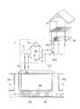
図1は、本発明により製造する製管用部材の一例を示す断面図であり、図2は、製管用部材を螺旋状に巻き回して管状に形成する様子を模式的に示す説明図である。また、図3は、本発明により製造する製管用部材の他の例を示す断面図である。
[Pipe making members]
FIG. 1 is a cross-sectional view showing an example of a pipe-making member manufactured according to the present invention, and FIG. 2 is an explanatory view schematically showing a state in which the pipe-making member is spirally wound to be formed into a tubular shape. Moreover, FIG. 3 is sectional drawing which shows the other example of the member for pipe manufacture manufactured by this invention.
製管用部材1は、長尺の帯状部材10を有する。帯状部材10は、長尺の基板100に、長手方向に沿って断面略T字状の複数条のリブ(長リブ103および短リブ107)が立設されている。帯状部材10のリブ103,107を有する面の反対側には、長手方向に沿って凹溝110が設けられている。以下、帯状部材10において、リブ103,107を有する面を表面、反対側の面を裏面と称する。
The pipe-making
帯状部材10には、基板100の一側縁に、長手方向に沿って接合凹部102が設けられ、基板100の他側縁には、長手方向に沿って接合凸部101が設けられている。
The band-shaped
接合凸部101は、基板100の表面に立設され、支柱部104と、支柱部104の先端に形成された断面略円形状の嵌入部105とを備える。接合凹部102は、基板100の裏面に開口する被嵌入部106と、基板100の幅方向外側に向かって延設され、途中で表面方向に屈折された傾斜片108とを備える。被嵌入部106の反対側(帯状部材10の表面側)には短リブ107が立設されている。接合凸部101と接合凹部102との間には、複数条の長リブ103が長手方向に沿って配設されている。
The joint
かかる帯状部材10は、硬質塩化ビニル、ポリエチレン、ポリプロピレン等の各種合成樹脂系材料を用いて、連続押出成形により長尺状に形成されている。
The
製管用部材1として、帯状部材10には補強材20が装着されている。補強材20は、鉄材、鋼材等の金属材料により形成されるほか、例えば、ガラスや炭素等の繊維補強材とポリエチレン、ポリプロピレン等の合成樹脂(熱可塑性、熱硬化性)による複合材料からなるものであってもよい。また補強材20として、補強効果を有する金属材料に、合成樹脂、ゴム等の被覆材または塗料が積層されたり、クロムや亜鉛等によるメッキが施されたりして形成された積層材料であってもよい。補強材20の断面形状は、更生対象管路に要求される強度に応じて、W字状、I字状、T字状、コ字状、矩形状、円形状等に形成され、どのような形状であってもよい。例示する補強材20は、帯板状の鋼板を断面略W字状に折曲して形成されている。
A reinforcing
補強材20は、帯状部材10の隣り合う長リブ103間に嵌め込まれて、略W字状の両端縁がそれぞれ長リブ103のT字状部分に係止されている。これによって、補強材20は帯状部材10の長手方向に連続的に配設されている。
The reinforcing
帯状部材10の凹溝110には、採熱用の管状体30が装着されている。凹溝110は帯状部材10の裏面側に開口しており、断面略U字状の形状にて形成されている。凹溝110の開口縁部には、溝の内側に向かって突出する突条111が設けられている。管状体30は、可撓性を有する中空パイプ(丸パイプ)からなり、帯状部材10の裏面側の凹溝110に嵌入されている。嵌入された管状体30は、凹溝110の突条111に係止して抜け止めが図られている。帯状部材10の凹溝110の反対側(帯状部材10の表面側)には短リブ107が一体に立設されている。
A
図2に示すように、製管用部材1は、螺旋状に巻き回されることにより、先行する製管用部材1の一側縁と周回遅れで後続する製管用部材1の他側縁とが接合されてライニング管200が形成される。すなわち、製管用部材1は、螺旋状に巻き回すことによって隣接した製管用部材1のうち、先行する製管用部材1の接合凹部102に、後続する製管用部材1の接合凸部101を嵌め込むことで接合される。このとき、先行する製管用部材1の傾斜片108は押圧され、後続する製管用部材1の長リブ103の先端部下面に嵌め込まれる(図1参照)。
As shown in FIG. 2, the pipe-forming
なお、製管用部材1は、図3に示すように、採熱用の管状体30が可撓性を有する角パイプからなるものであってもよい。この場合、帯状部材10の凹溝110は、断面略矩形状に形成されている。帯状部材10の凹溝110の反対側(帯状部材10の表面側)には、2条の短リブ107が一体に立設されている。
In addition, as shown in FIG. 3, the tube-forming
また、製管用部材1としては、一側縁に沿って設けられた接合凹部102に、他側縁に設けられた接合凸部101を嵌め込まれることによって製管されるものに限られず、例えば、螺旋状に巻き回すことによって隣接させた長尺の帯状部材の一側縁と他側縁とが、帯状部材とは別体の別体の接合部材(ジョイナー)にて接合される構成であってもよい。また製管用部材1は、帯状部材10の複数の凹溝にそれぞれ管状体が嵌め込まれた構成であってもよい。
In addition, the pipe-making
[製造方法]
次に、実施の形態に係る製管用部材1の製造方法について図面を参照しつつ説明する。図4は、製管用部材1の製造方法を模式的に示す説明図であり、図5は、帯状部材10に対して各部材を嵌合する様子を示す説明図である。
[Production method]
Next, the manufacturing method of the pipe-making
製管用部材1を製造するに際し、あらかじめ帯状部材10を連続押出成形により長尺状に形成する。形成した帯状部材10は、ドラム41の巻取軸に巻き重ねて保管し、製管用部材1の製造工程へ送る。補強材20および管状体30も同様に、あらかじめ形成しておき、それぞれドラム42、43の巻取軸に巻き重ねて保管し、製管用部材1の製造工程へ送る。
When manufacturing the
製造工程においては、帯状部材10をドラム41から引き出し、帯状部材10の長手方向を搬送方向として設定し、補強材嵌合工程、および管状体嵌合工程へと、順次、帯状部材10を送る。
In the manufacturing process, the belt-
帯状部材10の搬送経路は、巻き癖を有する帯状部材10の曲率に沿わせて規定する。搬送経路には、複数組のピンチローラを配設している。例示の形態では、帯状部材10の搬送経路に、2組のピンチローラ51、52を相互に間隔を設けて配置している。また、搬送経路上には、図示しない回転自在なガイドローラを複数箇所に配設して、帯状部材10を搬送経路の前方へ送るように構成している。
The conveyance path | route of the strip | belt-shaped
2組のピンチローラ51、52のうち、搬送経路の前方に配置したピンチローラ51はモータ等の回転駆動手段を備えて回転駆動される駆動ローラである。搬送経路の後方に配置したピンチローラ52は、回転駆動手段を備えない回転自在なフリーローラである。これらのピンチローラ51、52は、図示しない昇降手段により昇降可能に設けられている。
Of the two sets of
ドラム41から引き出した帯状部材10を各ピンチローラ51、52の各ローラ間に挿通して、ピンチローラ51、52にて挟持する。前方のピンチローラ51の直近には、ドラム42に巻き取った補強材20を用意する。次いで、ピンチローラ51と帯状部材10との間に、ドラム42から引き出した補強材20を供給する。具体的には、図5に示すように、帯状部材10の表面の2条の長リブ103間に補強材20を嵌入していく。
The belt-
後方のピンチローラ52の直近には、ドラム43に巻き取った管状体30を用意する。次いで、ピンチローラ52と帯状部材10との間に、ドラム43から引き出した管状体30を供給する。これにより、図5に示すように、帯状部材10の裏面の凹溝110に管状体30を嵌入していく。
A
帯状部材10に対する補強材20の嵌合および管状体30の嵌合は、ピンチローラ51の回転駆動によって進める。図4に示すように、前方のピンチローラ51を回転駆動させることで、帯状部材10をドラム41から引き出し、ピンチローラ51、52に引き込み、搬送経路の前方へ送っていく。これとともに、ピンチローラ51に挟持された帯状部材10には、表面側の長リブ103間に補強材20が押し込まれ、嵌合する(補強材嵌合工程)。
The fitting of the reinforcing
ピンチローラ51の回転駆動によって、後方のピンチローラ52は従動回転する。これにより、ピンチローラ52に挟持された帯状部材10の凹溝110に、管状体30が順次押し込まれていき、管状体30が嵌合する(管状体嵌合工程)。
As the
前述のとおり、形成した帯状部材10をドラムに巻き重ねていると、ドラムの巻取軸の曲率半径に沿って、または先に巻き重ねた帯状部材10に沿って帯状部材10に巻き癖が生じている。帯状部材10は、リブ103、107が立設された表面を外周側として螺旋状に巻回されライニング管200を構成することとなる。そのため、帯状部材10は、この螺旋状を考慮して表面側を外周に向けてドラム41に巻き取られており、曲線状の巻き癖がついている。
As described above, when the formed band-shaped
また、補強材20および管状体30においても、ドラム42、43に巻き取られていることによって巻き癖が生じている。巻き癖の生じたこれらの長尺材は、その巻き癖を修正することが容易ではなく、巻き癖を保持したまま各工程へ搬送することとなる。
Further, also in the reinforcing
しかしながら、長尺材を搬送する際、生じた巻き癖の曲げ形状の内側と外側とで、その長尺材の送り量にずれを生じてしまう。すなわち、図6に例示するように、帯状部材10の曲げ形状の内側と外側とでは、帯状部材10の厚み分に対応して、曲率半径に内外差が生じている。このような帯状部材10をピンチローラで挟持して搬送するとき、帯状部材10の曲げ形状の外側に当接して回転するローラAと、帯状部材10の曲げ形状の内側に当接して回転するローラBとが同期回転していても、帯状部材10の曲げ形状の内側は、その外側よりも速く送られることとなる。
However, when a long material is conveyed, a deviation occurs in the feed amount of the long material between the inner side and the outer side of the bent shape of the curl. That is, as illustrated in FIG. 6, there is an internal / external difference in the radius of curvature corresponding to the thickness of the band-shaped
仮に、一組のピンチローラを回転駆動させて、このピンチローラに挟み込んだ帯状部材10に対して、補強材20も管状体30も同時に嵌合しようとすると、帯状部材10の曲げ形状の内側から供給される管状体30に過大な負荷がかかる。そのため、管状体30は、変形したり破損したりするおそれがあり、帯状部材10に良好に嵌合されない。また、管状体30の嵌合状態に不良があると、ライニング管200の形成過程で、帯状部材10が螺旋状に巻き回されたときに、管状体30が波打ったり、帯状部材10から脱落したりするおそれがある。
If a pair of pinch rollers is driven to rotate and the reinforcing
これに対し、実施の形態に係る製管用部材1の製造方法においては、図7に示すように、搬送経路に複数組にピンチローラ51、52を離間して設け、そのうちの一組のピンチローラ51を回転駆動させることとし、回転駆動するピンチローラ51にて補強材20を嵌合し、従動回転するピンチローラ52にて管状体30を嵌合している。これにより、巻き癖を有する帯状部材10に対して、異なる曲率の巻き癖を有する補強材20および管状体30を円滑に嵌合することが可能となる。
On the other hand, in the method for manufacturing the pipe-making
特に、帯状部材10の曲げ形状の内側に送り込む管状体30を、その送り量のずれによって変形させたり破損させたりすることを防ぐことができるので、精度よく帯状部材10の凹溝110に嵌合することが可能となる。
In particular, it is possible to prevent the
管状体30としては、可撓性を有する丸パイプ(例えば、積水化学工業株式会社製、商品名:エスロペックス、又は、商品名:エスロメタックス。)を用いることができる。管状体30として丸パイプを用いた場合、管状体30を帯状部材10の凹溝110に嵌合する際の方向性に制限がなくなる。また、管状体30として丸パイプを用いることで、製管時において製管用部材1にねじれが生じたとしても、製管用部材1のねじれに対して管状体30が良好に追随し得るので、変形や脱落が生じ難いものとなる。
As the
上記のように帯状部材10に対して補強材20および管状体30をともに嵌合し、製管用部材1を形成することができる。形成した製管用部材1を、順次、搬送経路の前方へ送り、ドラム44の巻取軸に巻き取る。
As described above, the reinforcing
なお、製管用部材1の製造方法として、2組のピンチローラ51、52を搬送経路に設けるに限らず、さらにピンチローラの数を増やして搬送経路の複数箇所にピンチローラを設け、帯状部材10を搬送するように構成してもよい。このような場合にあっても、回転駆動させていないピンチローラにおいて管状体嵌合工程を行うことで、巻き癖を有する帯状部材10に対して精度よく円滑に管状体30を装着することができる。また、管状体嵌合工程と補強材嵌合工程は、上記形態に限られず、搬送経路上においてどちらの工程が先行するものであってもよい。
In addition, as a manufacturing method of the
[採熱構造]
次に、製管用部材1を用いて構築する採熱構造について説明する。図8は、製管用部材1を用いて構築した採熱構造の一例を示す説明図であり、図9は、製管用部材1を用いて製管されたライニング管200を模式的に示す斜視図である。
[Heat collection structure]
Next, a heat collection structure constructed using the pipe-making
ライニング管200は、下水が流通する埋設管300内において、製管用部材1を螺旋状に巻き回すことによって製管される。埋設管300の内壁とライニング管200の外周面との間の間隙には、モルタル等の裏込め材が充填される。
The
管状体30としての中空パイプは、帯状部材10の凹溝110に嵌合された状態で製管用部材1に設けられているので、図9に模式的に示すように、ライニング管200の内周面に部分的に露出した状態で螺旋状に配設される。
Since the hollow pipe as the
ライニング管200には、かかる管状体30を含む採熱管路60が構成されている。採熱管路60の一端と他端には、配管Pが連結されている。各配管Pは、それぞれ埋設管300に通じる一次側マンホール301、または、二次側マンホール302のいずれかを通じて地上に導かれ、地上に配置されたヒートポンプ3に接続されている。採熱管路60および配管Pによって構築された循環路には、水、グリコール、または水‐グリコール混合液などの伝熱媒体が図示しないポンプによって通液されている。これにより、循環路は、採熱管路60を熱交換器とする二次回路(伝熱媒体回路)TCとなされる。
The
以下、二次回路TCにおける、採熱管路60からヒートポンプ3に向かう伝熱媒体の流れを二次回路側往流TC1と称し、ヒートポンプ3から採熱管路60に向かう伝熱媒体の流れを二次回路側複流TC2と称する。
Hereinafter, the flow of the heat transfer medium from the
ヒートポンプ3には、蒸発器31と、圧縮機(コンプレッサ)32と、凝縮器33と、膨張弁34とからなる冷媒回路RCが構築されている。冷媒回路RCには、作動媒体(冷媒)が循環される。蒸発器31には、二次回路TCが接続されており、二次回路TCにおける二次回路側往流TC1は、蒸発器31を経由して、二次回路側複流TC2となり、採熱管路60に返送される仕組みとなっている。
In the heat pump 3, a refrigerant circuit RC including an
ヒートポンプ3における凝縮器33には、一次回路(熱媒回路)HCが連結されている。一次回路HCには、水等の熱媒が通液されている。熱媒は、図示しないポンプによって、一次回路HCを循環し、凝縮器33から熱利用システムHSを経由して、凝縮器33に返送される。
A primary circuit (heat medium circuit) HC is connected to the
以下、一次回路HCにおける、凝縮器33から熱利用システムHSに向かう熱媒の流れを一次回路側往流HC1と称し、熱利用システムHSから凝縮器33に向かう熱媒の流れを二次回路側複流HC2と称する。
Hereinafter, the flow of the heat medium from the
熱利用システムHSを、例えば、家屋内の床下暖房やヒーター、或いは暖房エアコン等の暖房設備として利用する場合にあっては、ヒートポンプ3を加熱機として使用する。この場合、図8に示すように、冷媒回路RCにおける作動媒体(冷媒)の流れは、図中矢印で示す方向に循環され、蒸発器31から、圧縮機32、凝縮器33、膨張弁34の順に経由して蒸発器31に戻る。
For example, when the heat utilization system HS is used as heating equipment such as underfloor heating or a heater in a house or a heating air conditioner, the heat pump 3 is used as a heater. In this case, as shown in FIG. 8, the flow of the working medium (refrigerant) in the refrigerant circuit RC is circulated in the direction indicated by the arrow in the figure, and from the
このような構成を有する採熱構造において、熱源としての下水熱を利用するには、ヒートポンプ3を作動させて、冷媒回路RCにおいて作動媒体を循環させる。また、一次回路HCにおいて熱媒を循環させるとともに、二次回路TCにおいて伝熱媒体を循環させる。 In the heat collection structure having such a configuration, in order to use sewage heat as a heat source, the heat pump 3 is operated and the working medium is circulated in the refrigerant circuit RC. Further, the heat medium is circulated in the primary circuit HC, and the heat transfer medium is circulated in the secondary circuit TC.
ライニング管200の上流側を流れる下水は一定の水温を有しており、ライニング管200を通過する際に、採熱管路60からなる熱交換器によって採熱される。これにより、下水の水温は低下し、二次回路TCにおける二次回路側往流TC1が昇温する。例えば、採熱構造の定常運転時において、ライニング管200の上流側を流れる下水の水温は、12〜20度程度であり、ライニング管200の下流側を流下する下水の水温は、9〜17度である。
The sewage flowing upstream of the
下水から採熱することによって昇温した伝熱媒体は、二次回路側往流TC1となって、蒸発器31に至り、蒸発器31内にて作動媒体に熱を放出する。この際、熱を受け取った作動媒体は気化する。一方、熱を放出した伝熱媒体は二次回路TCにおける二次回路側複流TC2となり、採熱管路60に戻る。すなわち、二次回路TCにおいて、伝熱媒体は、下水熱を受け取ることによる昇温と、作動媒体に熱を放出することによる降温を繰り返しながら、二次回路TCを循環する。採熱構造の定常運転時において、例えば、二次回路側往流TC1の液温は6〜14度程度であり、二次回路側複流TC2の液温は3〜11度程度である。
The heat transfer medium heated by collecting heat from the sewage becomes the secondary circuit side forward flow TC1, reaches the
伝熱媒体から熱を受け取って気化した作動媒体は、冷媒回路RCを通じて圧縮機32内に導入され、圧縮機32内で圧縮されることによって、更に昇温する。
The working medium that has vaporized by receiving heat from the heat transfer medium is introduced into the
圧縮機32によって圧縮されて昇温した作動媒体は、冷媒回路RCを通じて凝縮器33に至り、凝縮器33内にて熱媒に熱を放出する。この際、熱を受け取った熱媒は昇温する。一方、熱を放出した作動媒体は液化し、膨張弁34にて減圧された上で、蒸発器31に戻る。すなわち、冷媒回路RCにおいて、作動媒体は気化と液化を繰り返しながら、冷媒回路RCを循環する。
The working medium compressed by the
作動媒体から熱を受け取った熱媒は、一次回路HCにおける一次回路側往流HC1となって、熱利用システムHSに至り、熱利用システムHSにおいて熱利用される。これにより熱媒は降温し、一次回路側復流HC2となって、再度、凝縮器33に至る。すなわち、熱媒は、作動媒体から熱を受け取ることによる昇温と、熱利用システムHSにおいて熱利用されることによる降温とを繰り返しながら、一次回路HCを循環する。採熱構造の定常運転時において、例えば、一次回路側往流HC1の液温は35〜65度程度であり、一次回路側複流HC2の液温は25〜55度程度であった。
The heat medium that has received heat from the working medium becomes the primary circuit side forward flow HC1 in the primary circuit HC, reaches the heat utilization system HS, and is used in the heat utilization system HS. As a result, the temperature of the heat medium is lowered, becomes the primary circuit side return HC2, and reaches the
このような採熱構造においては、埋設管300内において製管用部材1を巻き回すことによってライニング管200を形成するだけで、熱交換器として用いられる採熱管路60を埋設管300内に設置することができる。これにより、地面を掘り下げて埋設管300を露出させる作業を行うことなく、熱交換器を埋設管300内に配置することができる。
In such a heat collection structure, the
採熱構造においては、熱交換器として機能する採熱管路60が、ライニング管200の管壁を周回するように螺旋状に配置されることから、ライニング管200内のいずれの箇所からも効果的に採熱することが可能であり、下水熱が最も生じるとされる管底部からも効果的に採熱することができる。
In the heat collection structure, the
また、ライニング管200の形成後に、管状体30を取り付けていく等の後工程が不要となり、埋設管300が通水状態であっても良好に施工することができ、短時間で作業を済ませることが可能となる。
In addition, after the
以上の採熱構造においては、埋設管300として下水道管を例示し、下水熱を熱源として利用しているが、採熱構造が構築される埋設管300としては、管内を水が流下しているものであれば良く、下水道管に限られない。埋設管300として、例えば、上水道管や農業用水管などの各種通水管を選択することができ、各種通水管内を流下する流水が保有する熱(水熱)を熱源として利用することができる。
In the above heat collection structure, a sewage pipe is illustrated as the buried
採熱構造を構築するための製管用部材1には、管状体30が1本設けられた構成であるが、これに限られず、管状体30が複数本設けられてもよい。その場合、複数の採熱管路60を備えるライニング管200が形成され、一ないし複数の採熱管路60を熱交換器として利用することができる。複数の採熱管路60を熱交換器として利用すれば、採熱効率をさらに向上させることができる。
The tube-forming
上記採熱構造においては、熱利用システムHSを暖房設備として利用すべく、ヒートポンプ3を加熱機として用いているが、下水の水温は、大気温と比較して夏季は冷たい一方で冬季は温かいことから、温熱利用のみならず冷熱利用も可能である。したがって、夏季においては、ヒートポンプ3を冷凍機として用いることによって、熱利用システムHSを冷房設備或いは年間を通じて利用される冷暖房システムとして利用することもできる。なお、ヒートポンプ3を冷凍機として用いる場合には、冷媒回路RCにおける作動媒体(冷媒)を、図8の矢印で示す方向と逆方向に循環させればよい。 In the above heat collection structure, the heat pump 3 is used as a heater in order to use the heat utilization system HS as a heating facility. However, the temperature of the sewage is cold in summer compared to the high temperature, but warm in winter. Therefore, not only the use of heat but also the use of cold energy is possible. Therefore, in summer, by using the heat pump 3 as a refrigerator, the heat utilization system HS can also be utilized as a cooling facility or a cooling / heating system utilized throughout the year. In addition, when using the heat pump 3 as a refrigerator, what is necessary is just to circulate the working medium (refrigerant) in the refrigerant circuit RC in the direction opposite to the direction shown by the arrow of FIG.
本発明は、地中に埋設された管路内に更生管を設け、採熱構造を構築するための製管用部材として好適に利用可能である。 INDUSTRIAL APPLICABILITY The present invention can be suitably used as a pipe making member for constructing a heat collection structure by providing a rehabilitation pipe in a pipe line buried in the ground.
1 製管用部材
10 帯状部材
100 基板
103 リブ(長リブ)
107 リブ(短リブ)
110 凹溝
20 補強材
30 管状体
200 ライニング管
300 埋設管
41,42,43,44 ドラム
51,52 ピンチローラ
60 採熱管路
DESCRIPTION OF
107 ribs (short ribs)
DESCRIPTION OF
Claims (6)
帯状部材は、長尺帯状の基板と、前記基板の一方の面に長手方向に立設された複数条のリブと、前記基板の他方の面に長手方向に形成された凹溝とを備え、ドラムの巻取軸に巻き取られており、
帯状部材の長手方向を搬送方向とし、搬送経路にピンチローラを配設し、
前記帯状部材を前記ピンチローラの各ローラ間に挿通し、
前記ピンチローラを駆動させて帯状部材を搬送経路の前方へ送るとともに、ピンチローラと帯状部材との間に、補強材を供給して帯状部材のリブ間に補強材を順次嵌合させつつ、管状体を供給して帯状部材の凹溝に管状体を順次嵌合させることを特徴とする製管用部材の製造方法。 A reinforcing member and the tube-like bodies in a strip elongated member A method of manufacturing a pipe-member provided integrally,
The band-shaped member includes a long band-shaped substrate, a plurality of ribs standing in the longitudinal direction on one surface of the substrate, and a groove formed in the longitudinal direction on the other surface of the substrate, It is wound around the drum winding shaft,
The longitudinal direction of the belt-shaped member is the transport direction, a pinch roller is disposed in the transport path,
Inserting the belt-like member between the rollers of the pinch roller;
The pinch roller is driven to feed the belt-shaped member forward of the conveying path, and the reinforcing material is supplied between the pinch roller and the belt-shaped member, and the reinforcing material is sequentially fitted between the ribs of the belt-shaped member, and the tubular A method for producing a pipe-making member, comprising: supplying a body and sequentially fitting a tubular body into a concave groove of a belt-like member.
帯状部材は、長尺帯状の基板と、前記基板の一方の面に長手方向に立設された複数条のリブと、前記基板の他方の面に長手方向に形成された凹溝とを備え、ドラムの巻取軸に巻き取られており、
帯状部材の長手方向を搬送方向とし、搬送経路に複数組のピンチローラを配設し、
前記ドラムから引き出して巻き癖がついた帯状部材を前記ピンチローラの各ローラ間に挿通し、
一組のピンチローラを駆動させて帯状部材を搬送経路の前方へ送るとともに、残りのピンチローラを従動回転させ、
回転駆動するピンチローラと帯状部材との間に補強材を供給して、帯状部材のリブ間に補強材を順次嵌合させつつ、従動回転するピンチローラと帯状部材との間に管状体を供給して、帯状部材の凹溝に管状体を順次嵌合させることを特徴とする製管用部材の製造方法。 A reinforcing member and the tube-like bodies in a strip elongated member A method of manufacturing a pipe-member provided integrally,
The band-shaped member includes a long band-shaped substrate, a plurality of ribs standing in the longitudinal direction on one surface of the substrate, and a groove formed in the longitudinal direction on the other surface of the substrate, It is wound around the drum winding shaft,
The longitudinal direction of the belt-shaped member is the transport direction, and a plurality of sets of pinch rollers are arranged in the transport path,
A belt-shaped member pulled out from the drum and having a curl is inserted between the rollers of the pinch roller,
While driving a set of pinch rollers to feed the belt-shaped member forward of the transport path, the remaining pinch rollers are driven to rotate,
A reinforcing material is supplied between the pinch roller to be rotated and the belt-like member, and a tubular body is supplied between the driven pinch roller and the belt-like member while sequentially fitting the reinforcing material between the ribs of the belt-like member. And the tubular body is sequentially fitted in the concave groove of the band-shaped member, and the manufacturing method of the member for pipe making characterized by the above-mentioned.
搬送経路の前方に回転駆動するピンチローラを設け、搬送経路の後方に従動回転するピンチローラを設けることを特徴とする製管用部材の製造方法。 In the manufacturing method of the member for pipe manufacture of Claim 2,
A method for manufacturing a pipe-making member, comprising: a pinch roller that is rotationally driven in front of a conveyance path; and a pinch roller that is driven to rotate rearward of the conveyance path.
前記補強材は金属製であることを特徴とする製管用部材の製造方法。 In the manufacturing method of the member for pipe manufacture as described in any one of Claims 1-3,
The method for manufacturing a pipe-making member, wherein the reinforcing material is made of metal.
巻き癖を有する帯状部材の曲率に沿わせた搬送経路を設定し、この搬送経路上に複数組のピンチローラを相互に間隔を設けて配設することを特徴とする製管用部材の製造方法。 In the manufacturing method of the member for pipe manufacture as described in any one of Claims 1-4,
A method for producing a pipe-making member, characterized in that a conveying path is set along the curvature of a belt-shaped member having a curl, and a plurality of sets of pinch rollers are arranged at intervals on the conveying path.
前記搬送経路上の複数箇所に帯状部材を案内する回転自在なガイドローラを配設することを特徴とする製管用部材の製造方法。 In the manufacturing method of the member for pipe manufacture as described in any one of Claims 1-5,
A method for producing a pipe-making member, comprising: a rotatable guide roller that guides a belt-like member at a plurality of locations on the conveyance path.
Priority Applications (1)
| Application Number | Priority Date | Filing Date | Title |
|---|---|---|---|
| JP2013186053A JP6114665B2 (en) | 2013-09-09 | 2013-09-09 | Method for manufacturing pipe-making member |
Applications Claiming Priority (1)
| Application Number | Priority Date | Filing Date | Title |
|---|---|---|---|
| JP2013186053A JP6114665B2 (en) | 2013-09-09 | 2013-09-09 | Method for manufacturing pipe-making member |
Publications (3)
| Publication Number | Publication Date |
|---|---|
| JP2015051597A JP2015051597A (en) | 2015-03-19 |
| JP2015051597A5 JP2015051597A5 (en) | 2016-04-28 |
| JP6114665B2 true JP6114665B2 (en) | 2017-04-12 |
Family
ID=52701001
Family Applications (1)
| Application Number | Title | Priority Date | Filing Date |
|---|---|---|---|
| JP2013186053A Active JP6114665B2 (en) | 2013-09-09 | 2013-09-09 | Method for manufacturing pipe-making member |
Country Status (1)
| Country | Link |
|---|---|
| JP (1) | JP6114665B2 (en) |
Families Citing this family (4)
| Publication number | Priority date | Publication date | Assignee | Title |
|---|---|---|---|---|
| JP6777498B2 (en) * | 2016-01-18 | 2020-10-28 | 積水化学工業株式会社 | Band-shaped member with tube, and its manufacturing method and manufacturing equipment |
| JP6273053B1 (en) * | 2017-01-17 | 2018-01-31 | 租 池田 | Heat collection pipe mechanism, manufacturing method thereof, and air conditioner |
| JP7040894B2 (en) * | 2017-02-15 | 2022-03-23 | 積水化学工業株式会社 | Manufacturing equipment and manufacturing method for pipeline rehabilitation members |
| JP7044579B2 (en) * | 2018-02-14 | 2022-03-30 | 積水化学工業株式会社 | A method for manufacturing a band-shaped member and a reinforcing band material for the band-shaped member. |
Family Cites Families (6)
| Publication number | Priority date | Publication date | Assignee | Title |
|---|---|---|---|---|
| JPH09152059A (en) * | 1995-11-28 | 1997-06-10 | Sekisui Chem Co Ltd | Method for lining for existing pipe |
| JP3657056B2 (en) * | 1996-05-23 | 2005-06-08 | 積水化学工業株式会社 | Profile for existing pipe lining |
| JP3786506B2 (en) * | 1997-07-15 | 2006-06-14 | 積水化学工業株式会社 | Lining method for existing pipes |
| JP3769367B2 (en) * | 1997-09-30 | 2006-04-26 | 積水化学工業株式会社 | Lining method for existing pipes |
| JP2013119227A (en) * | 2011-12-08 | 2013-06-17 | Sekisui Chem Co Ltd | Pipe manufacturing member and heat collecting structure |
| JP5753771B2 (en) * | 2011-12-08 | 2015-07-22 | 積水化学工業株式会社 | Pipe-making member and heat collection structure |
-
2013
- 2013-09-09 JP JP2013186053A patent/JP6114665B2/en active Active
Also Published As
| Publication number | Publication date |
|---|---|
| JP2015051597A (en) | 2015-03-19 |
Similar Documents
| Publication | Publication Date | Title |
|---|---|---|
| JP6114665B2 (en) | Method for manufacturing pipe-making member | |
| JP4938681B2 (en) | Absorber used for pipe structure or passage structure, and pipe structure or passage structure provided with such absorber | |
| KR100940400B1 (en) | A composite strip, a helically wound composite pipe, and a method of producing a helically wound steel reinforced plastics pipe | |
| US7476055B2 (en) | Underground and partly submerged pipe winding apparatus and method | |
| JP5155756B2 (en) | Apparatus for forming curl of strip-shaped member with reinforcing material, method for producing spiral tube, method for producing the same, and method for rehabilitating existing tube | |
| EP2136157A2 (en) | Tube assembly for geothermal heat exchanger | |
| DE202008017571U1 (en) | Tubular hollow profile | |
| CN101718375B (en) | Steel belt reinforced composite strip for spiral corrugated plastic steel winding pipe | |
| JP5914084B2 (en) | Heat collection system for sewage heat and its construction method | |
| JP5946754B2 (en) | Method for constructing double pipe structure with spiral pipe and pipe making machine used therefor | |
| JP5770535B2 (en) | Method for manufacturing pipe-making member | |
| JP5967878B2 (en) | Sleeve and method for manufacturing sleeve | |
| JP6087600B2 (en) | In-tube heat exchange system | |
| JP5753771B2 (en) | Pipe-making member and heat collection structure | |
| JP2013119227A (en) | Pipe manufacturing member and heat collecting structure | |
| WO2011005075A1 (en) | Heat exchanger | |
| WO2008113604A1 (en) | Tubular hollow profile and the use thereof | |
| JP2013242107A (en) | Heat collection structure for sewage heat or the like | |
| DE20320409U1 (en) | Earth heat probe has heat exchange tube inserted in earth and housing two-phase heat transfer medium, whereby at least heating zone of heat exchange tube is constructed as flexible coilable tubular material | |
| JP6777498B2 (en) | Band-shaped member with tube, and its manufacturing method and manufacturing equipment | |
| DE10327602A1 (en) | Ground heating probe for obtaining heat energy to generate electricity, includes heating pipe having heating zone which is made up of flexible pipe body which can be coiled up | |
| KR101723209B1 (en) | Winding device for plastic pipe | |
| JP6068739B2 (en) | Existing pipe rehabilitation material, heat exchanger laying method using the same, sewage pipe exhaust heat utilization system | |
| JP5836082B2 (en) | Resin pipe | |
| TWI269009B (en) | Water-permeable net pipe and manufacturing method thereof |
Legal Events
| Date | Code | Title | Description |
|---|---|---|---|
| A521 | Request for written amendment filed |
Free format text: JAPANESE INTERMEDIATE CODE: A523 Effective date: 20160311 |
|
| A621 | Written request for application examination |
Free format text: JAPANESE INTERMEDIATE CODE: A621 Effective date: 20160516 |
|
| A977 | Report on retrieval |
Free format text: JAPANESE INTERMEDIATE CODE: A971007 Effective date: 20170216 |
|
| TRDD | Decision of grant or rejection written | ||
| A01 | Written decision to grant a patent or to grant a registration (utility model) |
Free format text: JAPANESE INTERMEDIATE CODE: A01 Effective date: 20170221 |
|
| A61 | First payment of annual fees (during grant procedure) |
Free format text: JAPANESE INTERMEDIATE CODE: A61 Effective date: 20170317 |
|
| R151 | Written notification of patent or utility model registration |
Ref document number: 6114665 Country of ref document: JP Free format text: JAPANESE INTERMEDIATE CODE: R151 |
|
| R250 | Receipt of annual fees |
Free format text: JAPANESE INTERMEDIATE CODE: R250 |
|
| R250 | Receipt of annual fees |
Free format text: JAPANESE INTERMEDIATE CODE: R250 |