JP6113143B2 - Device having a heat exchanger for a thermoelectric generator of a motor vehicle - Google Patents
Device having a heat exchanger for a thermoelectric generator of a motor vehicle Download PDFInfo
- Publication number
- JP6113143B2 JP6113143B2 JP2014504273A JP2014504273A JP6113143B2 JP 6113143 B2 JP6113143 B2 JP 6113143B2 JP 2014504273 A JP2014504273 A JP 2014504273A JP 2014504273 A JP2014504273 A JP 2014504273A JP 6113143 B2 JP6113143 B2 JP 6113143B2
- Authority
- JP
- Japan
- Prior art keywords
- heat exchange
- duct
- fluid
- tube
- exchange tube
- Prior art date
- Legal status (The legal status is an assumption and is not a legal conclusion. Google has not performed a legal analysis and makes no representation as to the accuracy of the status listed.)
- Active
Links
- 239000012530 fluid Substances 0.000 claims description 68
- 238000002485 combustion reaction Methods 0.000 claims description 14
- 239000002826 coolant Substances 0.000 claims description 9
- 238000011144 upstream manufacturing Methods 0.000 claims description 2
- 239000000463 material Substances 0.000 description 8
- 238000006243 chemical reaction Methods 0.000 description 7
- 239000004065 semiconductor Substances 0.000 description 5
- 230000005679 Peltier effect Effects 0.000 description 3
- 230000005678 Seebeck effect Effects 0.000 description 3
- 229910052751 metal Inorganic materials 0.000 description 3
- 239000002184 metal Substances 0.000 description 3
- 229910052783 alkali metal Inorganic materials 0.000 description 2
- 150000001340 alkali metals Chemical class 0.000 description 2
- 229910021332 silicide Inorganic materials 0.000 description 2
- 229910017619 MgSn Inorganic materials 0.000 description 1
- 206010033733 Papule Diseases 0.000 description 1
- 238000010521 absorption reaction Methods 0.000 description 1
- 206010000496 acne Diseases 0.000 description 1
- 239000000919 ceramic Substances 0.000 description 1
- 238000005524 ceramic coating Methods 0.000 description 1
- 239000004020 conductor Substances 0.000 description 1
- 238000001816 cooling Methods 0.000 description 1
- 230000001419 dependent effect Effects 0.000 description 1
- 230000005292 diamagnetic effect Effects 0.000 description 1
- 230000000694 effects Effects 0.000 description 1
- 230000005611 electricity Effects 0.000 description 1
- 238000004146 energy storage Methods 0.000 description 1
- 238000007373 indentation Methods 0.000 description 1
- 238000009434 installation Methods 0.000 description 1
- 230000010354 integration Effects 0.000 description 1
- 229910000765 intermetallic Inorganic materials 0.000 description 1
- 150000002736 metal compounds Chemical class 0.000 description 1
- 238000000034 method Methods 0.000 description 1
- 230000000737 periodic effect Effects 0.000 description 1
- 239000004033 plastic Substances 0.000 description 1
- 229920003023 plastic Polymers 0.000 description 1
- 238000000926 separation method Methods 0.000 description 1
- FVBUAEGBCNSCDD-UHFFFAOYSA-N silicide(4-) Chemical compound [Si-4] FVBUAEGBCNSCDD-UHFFFAOYSA-N 0.000 description 1
- 229910052710 silicon Inorganic materials 0.000 description 1
- 239000010703 silicon Substances 0.000 description 1
- XLYOFNOQVPJJNP-UHFFFAOYSA-N water Substances O XLYOFNOQVPJJNP-UHFFFAOYSA-N 0.000 description 1
Images


Classifications
-
- F—MECHANICAL ENGINEERING; LIGHTING; HEATING; WEAPONS; BLASTING
- F28—HEAT EXCHANGE IN GENERAL
- F28F—DETAILS OF HEAT-EXCHANGE AND HEAT-TRANSFER APPARATUS, OF GENERAL APPLICATION
- F28F1/00—Tubular elements; Assemblies of tubular elements
-
- F—MECHANICAL ENGINEERING; LIGHTING; HEATING; WEAPONS; BLASTING
- F01—MACHINES OR ENGINES IN GENERAL; ENGINE PLANTS IN GENERAL; STEAM ENGINES
- F01N—GAS-FLOW SILENCERS OR EXHAUST APPARATUS FOR MACHINES OR ENGINES IN GENERAL; GAS-FLOW SILENCERS OR EXHAUST APPARATUS FOR INTERNAL COMBUSTION ENGINES
- F01N3/00—Exhaust or silencing apparatus having means for purifying, rendering innocuous, or otherwise treating exhaust
- F01N3/02—Exhaust or silencing apparatus having means for purifying, rendering innocuous, or otherwise treating exhaust for cooling, or for removing solid constituents of, exhaust
- F01N3/04—Exhaust or silencing apparatus having means for purifying, rendering innocuous, or otherwise treating exhaust for cooling, or for removing solid constituents of, exhaust using liquids
- F01N3/043—Exhaust or silencing apparatus having means for purifying, rendering innocuous, or otherwise treating exhaust for cooling, or for removing solid constituents of, exhaust using liquids without contact between liquid and exhaust gases
-
- F—MECHANICAL ENGINEERING; LIGHTING; HEATING; WEAPONS; BLASTING
- F01—MACHINES OR ENGINES IN GENERAL; ENGINE PLANTS IN GENERAL; STEAM ENGINES
- F01N—GAS-FLOW SILENCERS OR EXHAUST APPARATUS FOR MACHINES OR ENGINES IN GENERAL; GAS-FLOW SILENCERS OR EXHAUST APPARATUS FOR INTERNAL COMBUSTION ENGINES
- F01N5/00—Exhaust or silencing apparatus combined or associated with devices profiting from exhaust energy
- F01N5/02—Exhaust or silencing apparatus combined or associated with devices profiting from exhaust energy the devices using heat
-
- F—MECHANICAL ENGINEERING; LIGHTING; HEATING; WEAPONS; BLASTING
- F01—MACHINES OR ENGINES IN GENERAL; ENGINE PLANTS IN GENERAL; STEAM ENGINES
- F01N—GAS-FLOW SILENCERS OR EXHAUST APPARATUS FOR MACHINES OR ENGINES IN GENERAL; GAS-FLOW SILENCERS OR EXHAUST APPARATUS FOR INTERNAL COMBUSTION ENGINES
- F01N3/00—Exhaust or silencing apparatus having means for purifying, rendering innocuous, or otherwise treating exhaust
- F01N3/02—Exhaust or silencing apparatus having means for purifying, rendering innocuous, or otherwise treating exhaust for cooling, or for removing solid constituents of, exhaust
- F01N3/04—Exhaust or silencing apparatus having means for purifying, rendering innocuous, or otherwise treating exhaust for cooling, or for removing solid constituents of, exhaust using liquids
-
- F—MECHANICAL ENGINEERING; LIGHTING; HEATING; WEAPONS; BLASTING
- F01—MACHINES OR ENGINES IN GENERAL; ENGINE PLANTS IN GENERAL; STEAM ENGINES
- F01N—GAS-FLOW SILENCERS OR EXHAUST APPARATUS FOR MACHINES OR ENGINES IN GENERAL; GAS-FLOW SILENCERS OR EXHAUST APPARATUS FOR INTERNAL COMBUSTION ENGINES
- F01N5/00—Exhaust or silencing apparatus combined or associated with devices profiting from exhaust energy
- F01N5/02—Exhaust or silencing apparatus combined or associated with devices profiting from exhaust energy the devices using heat
- F01N5/025—Exhaust or silencing apparatus combined or associated with devices profiting from exhaust energy the devices using heat the device being thermoelectric generators
-
- F—MECHANICAL ENGINEERING; LIGHTING; HEATING; WEAPONS; BLASTING
- F02—COMBUSTION ENGINES; HOT-GAS OR COMBUSTION-PRODUCT ENGINE PLANTS
- F02G—HOT GAS OR COMBUSTION-PRODUCT POSITIVE-DISPLACEMENT ENGINE PLANTS; USE OF WASTE HEAT OF COMBUSTION ENGINES; NOT OTHERWISE PROVIDED FOR
- F02G5/00—Profiting from waste heat of combustion engines, not otherwise provided for
- F02G5/02—Profiting from waste heat of exhaust gases
-
- H—ELECTRICITY
- H10—SEMICONDUCTOR DEVICES; ELECTRIC SOLID-STATE DEVICES NOT OTHERWISE PROVIDED FOR
- H10N—ELECTRIC SOLID-STATE DEVICES NOT OTHERWISE PROVIDED FOR
- H10N10/00—Thermoelectric devices comprising a junction of dissimilar materials, i.e. devices exhibiting Seebeck or Peltier effects
- H10N10/10—Thermoelectric devices comprising a junction of dissimilar materials, i.e. devices exhibiting Seebeck or Peltier effects operating with only the Peltier or Seebeck effects
- H10N10/13—Thermoelectric devices comprising a junction of dissimilar materials, i.e. devices exhibiting Seebeck or Peltier effects operating with only the Peltier or Seebeck effects characterised by the heat-exchanging means at the junction
-
- F—MECHANICAL ENGINEERING; LIGHTING; HEATING; WEAPONS; BLASTING
- F01—MACHINES OR ENGINES IN GENERAL; ENGINE PLANTS IN GENERAL; STEAM ENGINES
- F01N—GAS-FLOW SILENCERS OR EXHAUST APPARATUS FOR MACHINES OR ENGINES IN GENERAL; GAS-FLOW SILENCERS OR EXHAUST APPARATUS FOR INTERNAL COMBUSTION ENGINES
- F01N2240/00—Combination or association of two or more different exhaust treating devices, or of at least one such device with an auxiliary device, not covered by indexing codes F01N2230/00 or F01N2250/00, one of the devices being
- F01N2240/02—Combination or association of two or more different exhaust treating devices, or of at least one such device with an auxiliary device, not covered by indexing codes F01N2230/00 or F01N2250/00, one of the devices being a heat exchanger
-
- F—MECHANICAL ENGINEERING; LIGHTING; HEATING; WEAPONS; BLASTING
- F01—MACHINES OR ENGINES IN GENERAL; ENGINE PLANTS IN GENERAL; STEAM ENGINES
- F01N—GAS-FLOW SILENCERS OR EXHAUST APPARATUS FOR MACHINES OR ENGINES IN GENERAL; GAS-FLOW SILENCERS OR EXHAUST APPARATUS FOR INTERNAL COMBUSTION ENGINES
- F01N2240/00—Combination or association of two or more different exhaust treating devices, or of at least one such device with an auxiliary device, not covered by indexing codes F01N2230/00 or F01N2250/00, one of the devices being
- F01N2240/36—Combination or association of two or more different exhaust treating devices, or of at least one such device with an auxiliary device, not covered by indexing codes F01N2230/00 or F01N2250/00, one of the devices being an exhaust flap
-
- F—MECHANICAL ENGINEERING; LIGHTING; HEATING; WEAPONS; BLASTING
- F01—MACHINES OR ENGINES IN GENERAL; ENGINE PLANTS IN GENERAL; STEAM ENGINES
- F01N—GAS-FLOW SILENCERS OR EXHAUST APPARATUS FOR MACHINES OR ENGINES IN GENERAL; GAS-FLOW SILENCERS OR EXHAUST APPARATUS FOR INTERNAL COMBUSTION ENGINES
- F01N2260/00—Exhaust treating devices having provisions not otherwise provided for
- F01N2260/14—Exhaust treating devices having provisions not otherwise provided for for modifying or adapting flow area or back-pressure
-
- F—MECHANICAL ENGINEERING; LIGHTING; HEATING; WEAPONS; BLASTING
- F01—MACHINES OR ENGINES IN GENERAL; ENGINE PLANTS IN GENERAL; STEAM ENGINES
- F01N—GAS-FLOW SILENCERS OR EXHAUST APPARATUS FOR MACHINES OR ENGINES IN GENERAL; GAS-FLOW SILENCERS OR EXHAUST APPARATUS FOR INTERNAL COMBUSTION ENGINES
- F01N2410/00—By-passing, at least partially, exhaust from inlet to outlet of apparatus, to atmosphere or to other device
- F01N2410/02—By-passing, at least partially, exhaust from inlet to outlet of apparatus, to atmosphere or to other device in case of high temperature, e.g. overheating of catalytic reactor
-
- F—MECHANICAL ENGINEERING; LIGHTING; HEATING; WEAPONS; BLASTING
- F01—MACHINES OR ENGINES IN GENERAL; ENGINE PLANTS IN GENERAL; STEAM ENGINES
- F01N—GAS-FLOW SILENCERS OR EXHAUST APPARATUS FOR MACHINES OR ENGINES IN GENERAL; GAS-FLOW SILENCERS OR EXHAUST APPARATUS FOR INTERNAL COMBUSTION ENGINES
- F01N2470/00—Structure or shape of gas passages, pipes or tubes
- F01N2470/08—Gas passages being formed between the walls of an outer shell and an inner chamber
-
- F—MECHANICAL ENGINEERING; LIGHTING; HEATING; WEAPONS; BLASTING
- F01—MACHINES OR ENGINES IN GENERAL; ENGINE PLANTS IN GENERAL; STEAM ENGINES
- F01N—GAS-FLOW SILENCERS OR EXHAUST APPARATUS FOR MACHINES OR ENGINES IN GENERAL; GAS-FLOW SILENCERS OR EXHAUST APPARATUS FOR INTERNAL COMBUSTION ENGINES
- F01N2470/00—Structure or shape of gas passages, pipes or tubes
- F01N2470/24—Concentric tubes or tubes being concentric to housing, e.g. telescopically assembled
-
- F—MECHANICAL ENGINEERING; LIGHTING; HEATING; WEAPONS; BLASTING
- F28—HEAT EXCHANGE IN GENERAL
- F28D—HEAT-EXCHANGE APPARATUS, NOT PROVIDED FOR IN ANOTHER SUBCLASS, IN WHICH THE HEAT-EXCHANGE MEDIA DO NOT COME INTO DIRECT CONTACT
- F28D21/00—Heat-exchange apparatus not covered by any of the groups F28D1/00 - F28D20/00
- F28D21/0001—Recuperative heat exchangers
- F28D21/0003—Recuperative heat exchangers the heat being recuperated from exhaust gases
-
- F—MECHANICAL ENGINEERING; LIGHTING; HEATING; WEAPONS; BLASTING
- F28—HEAT EXCHANGE IN GENERAL
- F28D—HEAT-EXCHANGE APPARATUS, NOT PROVIDED FOR IN ANOTHER SUBCLASS, IN WHICH THE HEAT-EXCHANGE MEDIA DO NOT COME INTO DIRECT CONTACT
- F28D7/00—Heat-exchange apparatus having stationary tubular conduit assemblies for both heat-exchange media, the media being in contact with different sides of a conduit wall
- F28D7/16—Heat-exchange apparatus having stationary tubular conduit assemblies for both heat-exchange media, the media being in contact with different sides of a conduit wall the conduits being arranged in parallel spaced relation
- F28D7/163—Heat-exchange apparatus having stationary tubular conduit assemblies for both heat-exchange media, the media being in contact with different sides of a conduit wall the conduits being arranged in parallel spaced relation with conduit assemblies having a particular shape, e.g. square or annular; with assemblies of conduits having different geometrical features; with multiple groups of conduits connected in series or parallel and arranged inside common casing
- F28D7/1669—Heat-exchange apparatus having stationary tubular conduit assemblies for both heat-exchange media, the media being in contact with different sides of a conduit wall the conduits being arranged in parallel spaced relation with conduit assemblies having a particular shape, e.g. square or annular; with assemblies of conduits having different geometrical features; with multiple groups of conduits connected in series or parallel and arranged inside common casing the conduit assemblies having an annular shape; the conduits being assembled around a central distribution tube
-
- Y—GENERAL TAGGING OF NEW TECHNOLOGICAL DEVELOPMENTS; GENERAL TAGGING OF CROSS-SECTIONAL TECHNOLOGIES SPANNING OVER SEVERAL SECTIONS OF THE IPC; TECHNICAL SUBJECTS COVERED BY FORMER USPC CROSS-REFERENCE ART COLLECTIONS [XRACs] AND DIGESTS
- Y02—TECHNOLOGIES OR APPLICATIONS FOR MITIGATION OR ADAPTATION AGAINST CLIMATE CHANGE
- Y02T—CLIMATE CHANGE MITIGATION TECHNOLOGIES RELATED TO TRANSPORTATION
- Y02T10/00—Road transport of goods or passengers
- Y02T10/10—Internal combustion engine [ICE] based vehicles
- Y02T10/12—Improving ICE efficiencies
Description
本発明は、特に自動車両に配置される、熱電式発電機用の熱交換器を有する装置に関する。 The present invention relates to a device having a heat exchanger for a thermoelectric generator, in particular arranged in a motor vehicle.
自動車両の内燃機関からの排ガスは、熱エネルギーを呈する。そして、例えば、バッテリーまたは他のエネルギー貯蔵部に充電するために、および/または電気消費部に必要なエネルギーを直接供給するために、熱エネルギーは、熱電式発電機によって電気エネルギーに変換される。このようにして、大量のエネルギーが、自動車両の作動にとって利用可能となる。熱電式発電機の使用を通して、内燃機関のエネルギー効率は、さらに上昇する。 The exhaust gas from the internal combustion engine of the motor vehicle exhibits thermal energy. The thermal energy is then converted into electrical energy by a thermoelectric generator, for example to charge a battery or other energy storage and / or directly supply the necessary energy to the electricity consumer. In this way, a large amount of energy is available for operation of the motor vehicle. Through the use of thermoelectric generators, the energy efficiency of the internal combustion engine is further increased.
このタイプの熱電式発電機は、少なくとも多数の、可能ならモジュラー式の、熱電変換素子を有する。熱電材料は、熱エネルギーを電気エネルギーに効果的に変換できる(ゼーベック効果)およびその逆も同様(ペルチェ効果)の材料である。ゼーベック効果は、熱エネルギーの電気エネルギーへの変換の現象に基づいており、熱電エネルギーの生成に利用される。ペルチェ効果は、ゼーベック効果の逆であり、熱の吸収をともなう現象であり、異なる材料を通って流れる電流に関して生成される。ペルチェ効果は、例えば熱電冷却用にすでに提案された。 This type of thermoelectric generator has at least a large number of possibly thermoelectric conversion elements. Thermoelectric materials are materials that can effectively convert thermal energy into electrical energy (Seebeck effect) and vice versa (Peltier effect). The Seebeck effect is based on the phenomenon of conversion of thermal energy into electrical energy, and is used to generate thermoelectric energy. The Peltier effect is the opposite of the Seebeck effect, a phenomenon involving heat absorption, and is generated with respect to the current flowing through different materials. The Peltier effect has already been proposed, for example for thermoelectric cooling.
この種の熱電変換素子は、いわゆる高温側といわゆる低温側との間に位置する多数の熱電素子を好ましくは有する。熱電素子は、例えば、少なくとも2つの半導体ブロック(p型およびn型の)を備える。半導体ブロックの上側および下側(それぞれ高温側および低温側に向く)は、導電ブリッジに交互に接続される。セラミックプレートまたはセラミックコーティングまたは他のプラスチックおよび/または類似の材料は、金属ブリッジを絶縁する役に立ち、したがって、金属ブリッジ間に好ましくは配置される。温度勾配が半導体ブロックの両側に提供される場合、電位が形成される。この場合、熱は、1つの接触点(高温側)で吸収され、電子は、一方の側からつぎのブロックの高エネルギーバンドに移る。他方の側では、低エネルギーレベルに戻るために(低温側)、電子は、今度はエネルギーを放出することができる。電流の流れは、したがって、対応する温度勾配を与えられて、発生することができる。 This type of thermoelectric conversion element preferably has a number of thermoelectric elements located between the so-called high temperature side and the so-called low temperature side. The thermoelectric element includes, for example, at least two semiconductor blocks (p-type and n-type). The upper and lower sides of the semiconductor block (towards the high temperature side and the low temperature side, respectively) are alternately connected to the conductive bridge. Ceramic plates or ceramic coatings or other plastics and / or similar materials serve to insulate the metal bridges and are therefore preferably placed between the metal bridges. If a temperature gradient is provided on both sides of the semiconductor block, a potential is formed. In this case, heat is absorbed at one contact point (on the high temperature side) and electrons move from one side to the high energy band of the next block. On the other side, in order to return to a low energy level (cold side), the electrons can now release energy. A current flow can thus be generated given a corresponding temperature gradient.
熱電式発電機の設計において、そしてその自動車両への使用において、さまざまな課題は、解決されなければならない。とりわけ、存在する温度差が電気エネルギーへの変換のために効率的に変換することができるように、熱電変換素子内に良好な熱伝達が提供されなければならない。さらに、さまざまな負荷条件の下で作動する内燃機関の排気システムにおいては、熱電素子に適した温度レベルが提供されなければならない。この種の装置または排気システム内の熱電素子の配置は、これらの態様に関しても考慮されなければならない。 Various challenges have to be solved in the design of thermoelectric generators and in their use in motor vehicles. In particular, good heat transfer must be provided in the thermoelectric conversion elements so that the existing temperature differences can be efficiently converted for conversion to electrical energy. Furthermore, in an exhaust system of an internal combustion engine that operates under various load conditions, a temperature level suitable for the thermoelectric element must be provided. The arrangement of thermoelectric elements in this type of device or exhaust system must also be considered with respect to these aspects.
したがって、本発明の目的は、従来技術に関して強調される課題を少なくとも部分的に解決することである。特に、排ガスからの熱エネルギーの電気エネルギーへの変換において、高い効率を呈する装置を特定することが求められる。さらに、装置は、できるだけスペースをとらない構造を有しなければならず、特に自動車両の床下の領域における配置に適していなければならない。さらに、装置の自動車両への後からの設置は、統合のための扱いにくい手段を必要とすることなく可能でなければならない。 Accordingly, it is an object of the present invention to at least partially solve the problems highlighted with respect to the prior art. In particular, it is required to identify a device that exhibits high efficiency in the conversion of thermal energy from exhaust gas into electrical energy. Furthermore, the device must have a structure that takes up as little space as possible and must be particularly suitable for placement in the area under the floor of a motor vehicle. Furthermore, the later installation of the device in a motor vehicle must be possible without the need for cumbersome means for integration.
前記目的は、請求項1の特徴による装置によって達成される。本発明による装置の有利な実施形態は、従属請求項において特定される。請求項において個々に特定される特徴は、いかなる所望の技術的に好都合な仕方でも互いに組み合わされてよく、本発明のさらなる実施形態を形成してよい点に留意する必要がある。記述は、特に図に関連して、さらに本発明を説明し、本発明の補助的な実施形態を特定する。
The object is achieved by a device according to the features of
特に自動車両の内燃機関の排気システムにおいて配置するために、装置は、熱交換器を有する。熱交換器は、軸方向に沿って第1端部側に配置される流体のための入口を有し、かつ第2(反対の)端部側に出口を有する少なくとも1つのハウジングを有する。さらに、熱交換器は、少なくとも1つの外部シェルチューブおよび、それに関して同心的に配置される内部シェルチューブを有し、そして、入口に(直接)隣接する環状の第1のダクトおよび出口の(直接)上流に配置される環状の第2のダクトを有する。第1のダクトおよび第2のダクトは、内部シェルチューブと外部シェルチューブとの間の(環状の)中間空間において軸方向に延びる流体のための多数の流路によって接続される。いずれの場合も、多数の流路内には、少なくとも1つの熱交換チューブが配置される。したがって、流体は、入口を経て環状の第1のダクト内に流入し、続いて多数の流路を介して環状の第2のダクトに導かれる。流体は、その後、出口を経てハウジングを出る。 The device has a heat exchanger, in particular for placement in an exhaust system of an internal combustion engine of a motor vehicle. The heat exchanger has at least one housing having an inlet for the fluid disposed on the first end side along the axial direction and having an outlet on the second (opposite) end side. Furthermore, the heat exchanger has at least one outer shell tube and an inner shell tube arranged concentrically therewith and of the annular first duct and outlet (directly) adjacent (directly) to the inlet. ) It has an annular second duct arranged upstream. The first duct and the second duct are connected by a number of flow paths for fluid extending axially in an (annular) intermediate space between the inner shell tube and the outer shell tube. In any case, at least one heat exchange tube is disposed in the multiple flow paths. Therefore, the fluid flows into the annular first duct via the inlet, and is subsequently guided to the annular second duct via a number of flow paths. The fluid then exits the housing via the outlet.
ハウジングまたは内部および/または外部シェルチューブは、好ましくは丸く、特に円形または他の楕円/卵形状であるが、この種の形状に決して制限されない。流路を囲む中間空間は、外部シェルチューブおよび内部シェルチューブによって形成される。内部シェルチューブは、キャビティを囲む。入口および出口は、特に円筒状であり、内燃機関の排気ラインに接続される。排気ラインから、流体(例えば内燃機関の排ガス)は、環状の第1のダクト内に流入し、第1のダクトを通って、外部および内部シェルチューブ間の(環状の)中間空間に移される。特に、環状の第1のダクトは、入口を少なくとも部分的に囲む。しかしながら、第1のダクトは、円筒形状でもよく、入口に直接隣接してもよい。そうすると、流体は、第1のダクトを介して環状の中間空間に流れ込む。 The housing or inner and / or outer shell tube is preferably round, in particular circular or other oval / egg shape, but is in no way limited to this type of shape. The intermediate space surrounding the flow path is formed by the outer shell tube and the inner shell tube. An inner shell tube surrounds the cavity. The inlet and outlet are particularly cylindrical and are connected to the exhaust line of the internal combustion engine. From the exhaust line, fluid (eg, exhaust gas from an internal combustion engine) flows into the annular first duct and is transferred through the first duct to the (annular) intermediate space between the outer and inner shell tubes. In particular, the annular first duct at least partially surrounds the inlet. However, the first duct may be cylindrical and may be directly adjacent to the inlet. Then, the fluid flows into the annular intermediate space via the first duct.
装置の好適な改良において、少なくとも1つの流路は、熱交換チューブを有しない。前記流路は、したがって、例えば第1の環状のダクトにおよび/または入口に配置される制御エレメントによって流体を用いて満たされることのできるバイパスとして役立つ。全ての流体の流れが前記バイパスを介して熱交換チューブを過ぎて導かれることは、好ましくは可能である。熱交換チューブが十分に冷やされることができないように、排ガスの温度が高過ぎるときに、または、付加的な負担が冷却液供給源にかけられてはならないときに、これは特に必要である。さらに、熱交換チューブ上の流れの結果として1つの制御可能な熱損失だけが発生するという点で、下流に配置される排ガス処理コンポーネントでの熱の導入が制御されることも、したがって、可能である。熱エネルギーは、したがって、流体中に蓄えられたままであり、排気ラインに追加的に設けられる排ガス処理コンポーネントに対して熱交換器の下流において最初に消散される。バイパスを通る流れの制御および/または調整は、内燃機関の作動点を考慮に入れて、および/または流体の固有値(温度、圧力、流体組成)を考慮に入れて、好ましくは実行される。 In a preferred refinement of the device, at least one flow path does not have a heat exchange tube. Said flow path thus serves as a bypass that can be filled with fluid, for example by means of a control element arranged in the first annular duct and / or at the inlet. It is preferably possible for all the fluid flow to be directed past the heat exchange tube via the bypass. This is particularly necessary when the temperature of the exhaust gas is too high, or when an additional burden should not be placed on the coolant supply so that the heat exchange tubes cannot be cooled sufficiently. In addition, it is also possible to control the introduction of heat in the exhaust gas treatment component located downstream in that only one controllable heat loss occurs as a result of the flow over the heat exchange tubes. is there. The thermal energy therefore remains stored in the fluid and is first dissipated downstream of the heat exchanger for the exhaust treatment component additionally provided in the exhaust line. Control and / or regulation of the flow through the bypass is preferably performed taking into account the operating point of the internal combustion engine and / or taking into account the eigenvalues of the fluid (temperature, pressure, fluid composition).
装置の1つの有利な改良において、熱電素子は、熱交換チューブ内に設けられる。ここで、熱電素子は、特に熱交換チューブの軸方向において環状の形を順に積み重ねたものである。高温流体(排ガス)は、熱交換チューブの外側上を流れ、低温流体(水)は、内側ダクトにおいて熱交換チューブの中を流れる。このように熱交換チューブの外面と内側ダクトとの間に発生する温度勾配の結果、電気的に接続された熱電素子は、適切な電気的端子を介して熱交換器のハウジング上に摘まみ取る(pick off)ことのできる電流を発生する。このように、熱電式発電機によって発生する電流が自動車両に利用可能となることができるように、自動車両の電気貯蔵部または電気消費部に特に接続している熱電式発電機として、熱交換器を有する装置は、したがって、作動される。 In one advantageous refinement of the device, the thermoelectric element is provided in a heat exchange tube. Here, the thermoelectric element is obtained by sequentially stacking annular shapes in the axial direction of the heat exchange tube. The hot fluid (exhaust gas) flows on the outside of the heat exchange tube, and the cold fluid (water) flows in the heat exchange tube in the inner duct. As a result of the temperature gradient generated between the outer surface of the heat exchange tube and the inner duct in this way, the electrically connected thermoelectric elements are picked up on the heat exchanger housing via suitable electrical terminals. Generate a current that can be picked off. In this way, heat exchange as a thermoelectric generator especially connected to the electric storage or consumption part of the motor vehicle so that the current generated by the thermoelectric generator can be made available to the motor vehicle. The device with the vessel is thus activated.
熱電素子のための熱電材料として、特に以下が考慮される。
n型熱電材料:ケイ化物(例えばMgSi−MgSn)
p型熱電材料:ジントル相(例えばZn4Sb4)
In particular, the following are considered as thermoelectric materials for thermoelectric elements.
n-type thermoelectric material: silicide (eg MgSi-MgSn)
p-type thermoelectric material: Jintle phase (for example, Zn 4 Sb 4 )
前記材料は、特に有利であり、そして高温流体(排ガス)の熱エネルギーを電気エネルギーに効率的に変換することを許容することが判明した。ケイ化物は、特にシリコンの二成分金属化合物である。そしてそれは、半導体として利用されることができる。ジントル相は、特に、高い陽電性を帯びたアルカリ金属または接地アルカリ金属と、周期表の第13〜16群からの適度に電気陰性の元素との間の金属間化合物である。いくらかのジントル相は、金属導体と対照的に、伝導率が温度の増加とともに上昇する反磁性半導体である。 The material has been found to be particularly advantageous and allows efficient conversion of the thermal energy of the hot fluid (exhaust gas) into electrical energy. Silicides are in particular binary metal compounds of silicon. And it can be used as a semiconductor. The jintole phase is in particular an intermetallic compound between a highly positively charged alkali metal or grounded alkali metal and a moderately electronegative element from groups 13-16 of the periodic table. Some jintole phases are diamagnetic semiconductors whose conductivity increases with increasing temperature, in contrast to metal conductors.
装置のさらに有利な改良において、内部シェルチューブおよび/または外部シェルチューブは、軸方向に延びる、そして、中間空間において断面狭小部および断面拡幅部を円周方向に交互に形成する構造物を有する。断面拡幅部は、いずれの場合も1つの流路を形成する。構造物は、特に波打つ形のものであり、好ましくは正弦波の構造物である。特に、断面狭小部は、個々の流路を切り離さない。そうすると、流体の(限られた)交換は、円周方向に隣接する流路間で可能である。しかしながら、断面狭小部による流路の少なくとも部分的な分離は、本発明に同様に合致する。 In a further advantageous refinement of the device, the inner shell tube and / or the outer shell tube have a structure that extends in the axial direction and alternately forms a narrow section and a wide section in the circumferential direction in the circumferential direction. In any case, the cross-section widened portion forms one flow path. The structure is in particular wavy and is preferably a sinusoidal structure. In particular, the narrow cross section does not separate the individual channels. A (limited) exchange of fluid is then possible between the circumferentially adjacent channels. However, at least partial separation of the flow path by the narrowed section is consistent with the present invention as well.
特に、内部シェルチューブおよび外部シェルチューブは、構造物を備える。前記構造物は、断面狭小部および断面拡幅部が形成されるように、いずれの場合も2つのシェルチューブが円周方向に沿って一緒に接近し、または互いからさらに離れるように、互いに関して方向付けられる。特に、断面狭小部の最小幅に対する断面拡幅部の最大幅の比率(最大幅/最小幅)は、少なくとも2の、好ましくは少なくとも3の、特に好ましくは少なくとも5の値を有する。 In particular, the inner shell tube and the outer shell tube comprise a structure. The structures are oriented with respect to each other such that in each case the two shell tubes approach together or further away from each other so that a narrowed section and a widened section are formed. Attached. In particular, the ratio of the maximum width of the cross-section widened portion to the minimum width of the cross-sectional narrow portion (maximum width / minimum width) has a value of at least 2, preferably at least 3, particularly preferably at least 5.
特に、外部シェルチューブおよび/または内部シェルチューブは、熱交換チューブの外面に対して2〜7mm[ミリメートル]の(最小)間隔を伴って配置される。前記間隔は、熱交換チューブの利用できる外面上の流体の流れの有利な分布に結果としてなる。外部シェルチューブおよび/または内部シェルチューブの構造物は、特に、排ガスが熱交換チューブに近接してその熱交換チューブを過ぎて導かれるという点で、効果を有する。特に、熱交換チューブは、25〜35mm[ミリメートル]の、特に最大でも30mmの最大直径を有する。特に、熱交換チューブは、円周方向において4〜14mm[ミリメートル]の外面間の距離を伴って互いに離間する。 In particular, the outer shell tube and / or the inner shell tube are arranged with a (minimum) spacing of 2-7 mm [millimeter] relative to the outer surface of the heat exchange tube. The spacing results in an advantageous distribution of fluid flow over the available outer surface of the heat exchange tube. The structure of the outer shell tube and / or the inner shell tube is particularly advantageous in that the exhaust gas is guided close to the heat exchange tube and past the heat exchange tube. In particular, the heat exchange tube has a maximum diameter of 25 to 35 mm [millimeter], in particular at most 30 mm. In particular, the heat exchange tubes are separated from each other with a distance between the outer surfaces of 4 to 14 mm [millimeters] in the circumferential direction.
特に、流体/排ガスの方向転換を遂行することのできるガイドエレメントは、少なくとも1つの熱交換チューブにおよび/または少なくとも1つの流路に配置される。ガイドエレメントは、特に、内部シェルチューブにおよび/または外部シェルチューブに少なくとも部分的に固定される。前記ガイドエレメントは、熱交換チューブの周りで流体を方向転換するために、および/または隣接する熱交換チューブ間で流体を混合するために、および/または隣接する熱交換チューブに対して流体を少なくとも部分的に方向転換するために、特に役立つ。 In particular, a guide element capable of performing a fluid / exhaust gas redirection is arranged in at least one heat exchange tube and / or in at least one flow path. The guide element is in particular at least partially fixed to the inner shell tube and / or to the outer shell tube. The guide element may be configured to redirect fluid around a heat exchange tube and / or to mix fluid between adjacent heat exchange tubes and / or to at least transfer fluid to adjacent heat exchange tubes. Especially useful for partial turning.
さらなる改良において、少なくとも1つの熱交換チューブおよび/または少なくとも1つのガイドエレメントおよび/または内部シェルチューブおよび/または外部シェルチューブは、流体の流れの乱流を発生させるための構造を備える。前記構造は、増加した粗さによっておよび/または微小構造によって形成されてよい。前記構造は、熱交換チューブの周りの流体の流れの中で乱流を発生させる。そうすると、流体の流れから熱交換チューブへの熱の移動は、改善される。このようにして、増加した量の熱エネルギーは、流体の流れから抽出されて、熱交換チューブを介して消散される。このようにして、熱交換器のまたは熱電式発電機のより効率的な使用は、ここで可能である。特に、熱交換チューブおよび/またはガイドエレメントの全ては、前記タイプの構造を有する。 In a further refinement, the at least one heat exchange tube and / or the at least one guide element and / or the inner shell tube and / or the outer shell tube comprise a structure for generating turbulence of the fluid flow. The structure may be formed by increased roughness and / or by a microstructure. The structure generates turbulence in the fluid flow around the heat exchange tube. In so doing, heat transfer from the fluid flow to the heat exchange tubes is improved. In this way, an increased amount of thermal energy is extracted from the fluid flow and dissipated through the heat exchange tubes. In this way, more efficient use of heat exchangers or thermoelectric generators is possible here. In particular, all of the heat exchange tubes and / or guide elements have a structure of the type described above.
構造は、熱交換チューブの周りの流体の流れの中で乱流を発生させる。そうすると、流体の流れから熱交換チューブへの熱の移動は、改善される。このようにして、増加した量の熱エネルギーは、流体の流れから抽出されて、熱交換チューブを介して消散される。このようにして、熱交換器のまたは熱電式発電機のより効率的な使用は、ここで可能である。 The structure generates turbulence in the fluid flow around the heat exchange tube. In so doing, heat transfer from the fluid flow to the heat exchange tubes is improved. In this way, an increased amount of thermal energy is extracted from the fluid flow and dissipated through the heat exchange tubes. In this way, more efficient use of heat exchangers or thermoelectric generators is possible here.
特に、構造は、熱交換チューブ上に、そしてガイドエレメント上に、そして内部および外部シェルチューブ上に配置されて、それらの位置決めおよび流れに対するそれらの効果に関して互いに調整される。 In particular, the structures are arranged on the heat exchange tubes and on the guide elements and on the inner and outer shell tubes and are coordinated with each other with respect to their positioning and their effect on the flow.
特に、微小構造は、丘疹(pimple)および/またはギザギザ(indentation)の形に設計される。丘疹は、ガイドエレメント/熱交換チューブ/シェルチューブの表面から外向きに延出する。ギザギザは、内向きに延出する。 In particular, the microstructure is designed in the form of pimples and / or indentations. The papules extend outward from the surface of the guide element / heat exchange tube / shell tube. The jagged edges extend inward.
特に、構造は、増加した粗さによって形成される。ここで、熱電素子または低温流体に面する熱交換チューブのその表面上の粗さに対して、流体の流れに面する熱交換チューブのその表面の粗さは、増加する。ここで、熱交換チューブから向きがそれる内部および/または外部シェルチューブのその表面上の粗さに対して、熱交換チューブに面する内部および/または外部シェルチューブのその表面の粗さは、増加する。特に、熱交換チューブ上のおよび/または内部および/または外部シェルチューブ上の増加した粗さは、少なくとも5倍に、好ましくは少なくとも10倍に、特に好ましくは少なくとも20倍に増加する。粗さは、平均粗さRaまたは平均の粗さ深さRzとして決定される。特性粗さ値を決定する方法は、国際標準から(例えばDIN EN ISO 4287から)当業者に知られている。特に、バイパスは、乱流を増加させるための構造を有しない。特に、バイパスは、ガイドエレメントも有しない。 In particular, the structure is formed by increased roughness. Here, the roughness of the surface of the heat exchange tube facing the fluid flow is increased relative to the roughness of the surface of the heat exchange tube facing the thermoelectric element or cryogenic fluid. Here, the roughness of the surface of the inner and / or outer shell tube facing the heat exchange tube relative to the roughness of the inner and / or outer shell tube facing away from the heat exchange tube is: To increase. In particular, the increased roughness on the heat exchange tubes and / or on the inner and / or outer shell tubes is increased at least 5 times, preferably at least 10 times, particularly preferably at least 20 times. The roughness is determined as the average roughness Ra or the average roughness depth Rz. Methods for determining characteristic roughness values are known to the person skilled in the art from international standards (eg from DIN EN ISO 4287). In particular, the bypass does not have a structure for increasing turbulence. In particular, the bypass does not have a guide element.
さらに有利な改良において、熱交換チューブは、第1のダクトを越えておよび/または第2のダクトを越えて軸方向に延びる。熱交換チューブは、少なくとも1つの(共通の)ポートを介して冷却液供給源に接続される。ポートは、特に、低温流体が熱交換チューブと冷却液装置との間を循環することができるように、供給ラインおよび戻りラインを備える。特に、熱交換チューブは、1つのポートから個々の熱交換チューブへの低温流体の分配を許容する少なくとも1つの共通の閉鎖プレート上に配置される。ここで、いずれの場合も、1つの閉鎖プレートが第1端部側上におよび第2端部側上に配置されることも、可能である。そうすると、低温流体は、1つの軸方向の熱交換チューブの全体を通って流れる。 In a further advantageous refinement, the heat exchange tube extends axially beyond the first duct and / or beyond the second duct. The heat exchange tube is connected to the coolant supply via at least one (common) port. The port comprises in particular a supply line and a return line so that cryogenic fluid can circulate between the heat exchange tube and the coolant device. In particular, the heat exchange tubes are arranged on at least one common closing plate that allows the distribution of cryogenic fluid from one port to the individual heat exchange tubes. Here, in any case, it is also possible for one closing plate to be arranged on the first end side and on the second end side. The cryogenic fluid then flows through the entire one axial heat exchange tube.
熱交換器において、流体が放射状に通って流れることのできるハニカムボディが第1のダクトの中に配置されることは、特に可能である。前記ハニカムボディは、特に触媒的にコーティングされる。ハニカムボディは、入口に向かって開いているように形成される中央に配置された流入ダクトを有する。したがって、流体は、入口を経て流入ダクトに流れ込み、ハニカムボディの放射状に延びる流れダクトを通って中間空間へと前方へ導かれる。 In the heat exchanger, it is particularly possible that a honeycomb body through which fluid can flow radially is arranged in the first duct. The honeycomb body is coated in particular catalytically. The honeycomb body has a centrally arranged inflow duct formed so as to open toward the inlet. Thus, the fluid flows through the inlet into the inflow duct and is directed forward to the intermediate space through the radially extending flow duct of the honeycomb body.
内燃機関を有し、排ガス処理装置を有し、排気ラインに配置される本発明による装置をも有する自動車両において、本発明は、特に使用される。そして、流体は、内燃機関の排ガスである。特に、複数の装置が一本出しまたは他の複数本出しの排気ラインに設けられることは、明らかに可能である。 The invention is particularly used in motor vehicles having an internal combustion engine, having an exhaust gas treatment device and also having a device according to the invention arranged in an exhaust line. The fluid is exhaust gas from the internal combustion engine. In particular, it is clearly possible for a plurality of devices to be provided in one exhaust line or the other multiple discharge exhaust line.
装置は、後から排気ラインに取り付けられてもよい。そして、単に冷却液供給源への接続を提供することが必要なだけである。適切な場合、設けられるバイパスの対応する作動を実現するために、制御装置への接続も必要である。 The device may later be attached to the exhaust line. And it is only necessary to provide a connection to the coolant supply. If appropriate, a connection to the control device is also necessary in order to realize the corresponding operation of the bypass provided.
本発明および発明の技術分野は、図に基づいて以下にさらに詳細に説明される。図は、特に好適な例示的実施形態を示すが、本発明は、それに制限されない。 The invention and the technical field of the invention are explained in more detail below on the basis of the figures. The figure shows a particularly preferred exemplary embodiment, but the invention is not limited thereto.
図1は、熱交換器1を有する装置の縦断面を示す。流体8(または排ガス)は、第1端部側5の入口4を通り、そして流れに関して入口4に接続された流入ダクト36を通って、流れが放射状に通過することのできるハニカムボディ37へと流れ込む。ハニカムボディ37は、環状の第1の導管11内に配置される。流体8は、流れが放射状に通過することのできるハニカムボディ37を通って半径方向に流れる。そして、前記流体は、外部シェルチューブ9によっておよび内部シェルチューブ10によって形成される中間空間14に入る。中間空間14において、流体8は、軸方向3へと方向転換され、そして中間空間14を通って出口6の方向に流れる。前記図1において、中間空間14は、軸方向3において円筒状の設計である。例えば、軸方向3に沿って広がる中間空間14に対応して、円錐状の設計も可能である。
FIG. 1 shows a longitudinal section of a device having a
流体8は、熱交換チューブ15の周りに形成される多数の流路13に沿って軸方向3に第2のダクト12へ流れる。第2のダクト12において、流体8は、集められて、第2端部側7の出口6へと前方へ導かれる。熱交換チューブ15は、全ての中間空間14を通って軸方向3に延びる。流体8は、熱交換チューブ15の外面33上を流れる。「高温側」は、したがって、ここで形成される。熱交換チューブ15は、それらが低温流体31によって横断される内側ダクト32を有する。(特に環状の形である)熱電素子22は、内側ダクト32(「低温側」)と外面33(「高温側」)との間に配置される。熱電素子22とともにこの装置は、熱電式発電機を形成する。高温流体8(排ガス)は、熱交換チューブ15の外面33の周りを流れる。そうすると、低温側と高温側との間に温度ポテンシャルが発生する。前記温度ポテンシャルは、熱電素子22によって電気エネルギーへと変換される。
The
熱交換チューブ15は、いずれの場合も内部シェルチューブ10によっておよび外部シェルチューブ9によって形成される流路13内に配置される。ここで、外部シェルチューブ9は、ハウジング2を少なくとも部分的に形成する。外部シェルチューブ9および内部シェルチューブ10は、いずれの場合も熱交換チューブ15の外面33に対して間隔34を保って配置される。
The
閉鎖プレート26は、入口4のまたは第1端部側5の領域においてハウジング2上に設けられる。前記閉鎖プレート26は、第1に、軸方向3の中間空間14の範囲を定めるために、そして第2に、熱交換チューブ15を受け入れるために、役立つ。そうすると、熱交換チューブ15を通って流れる低温流体31は、供給されて、ここに放出される。冷却液供給源への接続のためのポート20は、閉鎖プレート26内に配置される。熱交換チューブ15は、閉鎖プレート26から第2端部側7まで中間空間14を通って延びる。そこでは、さらなる熱交換チューブ15を通って低温流体31を閉鎖プレート26に戻させる迂回路が設けられる。同時に、熱交換チューブ15の中の熱電素子22の配置のせいで、熱交換チューブ15の範囲内で高温流体8と冷たい低温流体31との間の温度差の結果として発生する電流が、自動車両に出力されることができるように、閉鎖プレート26内に電気的端子(図示せず)が設けられてよい。
A closing
図2は、熱交換器を有する装置のさらなる設計変形の縦断面を示す。図において、同じ参照符号が、同一の対象物のために用いられる。入口4の領域に、バイパスへと流体の流れを方向転換することのできる制御エレメント30が示される。バイパスは、熱交換チューブ15が配置されない(図示せず)流路13によって形成される。
FIG. 2 shows a longitudinal section of a further design variant of the device with a heat exchanger. In the figures, the same reference numerals are used for the same objects. In the region of the inlet 4 a
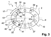
図3は、図1による熱交換器1を有する装置の図1に示される切断軸(III)に沿った断面を示す。ここで、ハウジング2は、外部シェルチューブ9によって形成されて、中間空間14および内部シェルチューブ10を囲む。熱交換チューブ15は、中間空間14内に配置される。中間空間14は、環状であり、内部シェルチューブ10によって内側に対して区切られる。内部シェルチューブ10は、キャビティ27を囲む。中間空間14には、流体8が中間空間14を通って流れることのできる多数の流路13が形成される。1つの熱交換チューブ15上に、流体の流れに乱流を発生させるための役に立つ構造39が示される。流体8と熱交換チューブ15との間の熱伝達は、前記構造39によって改良されることができる。
FIG. 3 shows a section along the cutting axis (III) shown in FIG. 1 of the device with the
図3の下部には、1つの熱交換チューブ15が横断面において詳細に示される。ここでは、熱交換チューブ15の中の環状の熱電素子22が示される。熱交換チューブ15は、円周方向17において互いに距離35で配置される。
In the lower part of FIG. 3, one
図3の左側の上半分には、外部シェルチューブ9のおよび内部シェルチューブ10の構造物16が示される(1点鎖線)。構造物16の結果、中間空間14内に、断面狭小部18および断面拡幅部19が円周方向17に形成される。ここで示される断面狭小部18を通って、隣接する断面拡幅部19の流路13間の流体8の交換は、円周方向17に可能である。断面狭小部18の最も狭い場所は、最小幅42を有する。断面拡幅部19の最も広い場所は、最大幅43を有する。
In the upper half of the left side of FIG. 3, the
流体8を少なくとも部分的に方向転換するガイドエレメント40は、図3にも示される。流体8が軸方向3に流れるだけでなく円周方向17および/または半径方向41にも流れるように、ガイドエレメント40によって、流体8は、個々の熱交換チューブ15の周りに導かれる。
A
図4は、自動車両23の中での熱交換器1を有する装置の配置を示す。自動車両23は、排気ライン25を有する内燃機関24を有し、そしてさらに排ガス処理コンポーネント28を有する。熱交換器1は、この場合、熱電式発電機29の形である。熱電式発電機29内に配置される熱交換チューブは、供給ラインおよび戻りラインを介して冷却液供給源21に接続される。バイパスを介して流れる排ガスの量が制御され得るように、熱交換器1内でなかでも制御エレメントの作動として役に立つ調整ユニット38もまた、設けられる。このようにして、排ガスは、熱交換チューブを過ぎて、そして、適切な場合、熱電式発電機29において排ガスによって内燃機関24の冷却液供給源21に付加的な負担がかからないように、熱電素子を過ぎて案内されることができる。
FIG. 4 shows the arrangement of the device with the
本発明の他の構成または設計変形は、可能である。特に、熱交換チューブ15が一端でだけでなく他端でも保持されるように、複数の閉鎖プレート26がハウジング2内に配置されることが可能である。流れが1つの軸方向3にだけ熱交換チューブ15を通過するように、ポート20がいずれの場合も別々の閉鎖プレート26に配置されることも、したがって可能である。ここに示される図では、低温流体31は、入口4の近くの閉鎖プレート26から第2端部側7へ、そして閉鎖プレート26へと戻る軸方向3において、熱交換チューブ15を通って流れる。特に、閉鎖プレート26は、装置の第2端部側7に配置されてもよい。
Other configurations or design variations of the invention are possible. In particular, a plurality of
同様に、流体8のためのバイパスがキャビティ27によって形成されることは、本発明の範囲内にある。流体8がキャビティ27を通って流れることができるように、前記バイパスは、次いで、入口4に向かって、そして出口6に向かって開いているように形成される。バイパスは、次いで、キャビティ27の中に配置される制御エレメント30として、フラップによって特に形成されてよい。フラップの開口の結果、流体8の少なくとも大部分は、キャビティ27を通って案内される。なぜなら、ここは、(流路13を通って案内される流体に関して)最も低い流動抵抗が優勢であるからである。この場合、制御エレメント30が内部シェルチューブ10でキャビティ27を密封閉鎖することができるように、内部シェルチューブ10は、少なくとも部分的に構造物16なしで形成される。
Similarly, it is within the scope of the present invention that a bypass for
1…熱交換器
2…ハウジング
3…軸方向
4…入口
5…第1端部側
6…出口
7…第2端部側
8…流体
9…外部シェルチューブ
10…内部シェルチューブ
11…第1のダクト
12…第2のダクト
13…流路
14…中間空間
15…熱交換チューブ
16…構造物
17…円周方向
18…断面狭小部
19…断面拡幅部
20…ポート
21…冷却液供給源
22…熱電素子
23…自動車両
24…内燃機関
25…排気ライン
26…閉鎖プレート
27…キャビティ
28…排ガス処理コンポーネント
29…熱電式発電機
30…制御エレメント
31…低温流体
32…内側ダクト
33…外面
34…間隔
35…距離
36…流入ダクト
37…ハニカムボディ
38…調整ユニット
39…構造
40…ガイドエレメント
41…半径方向
42…最小幅
43…最大幅
DESCRIPTION OF
Claims (5)
Applications Claiming Priority (3)
| Application Number | Priority Date | Filing Date | Title |
|---|---|---|---|
| DE201110016808 DE102011016808A1 (en) | 2011-04-13 | 2011-04-13 | Device with a heat exchanger for a thermoelectric generator of a motor vehicle |
| DE102011016808.7 | 2011-04-13 | ||
| PCT/EP2012/056407 WO2012139992A2 (en) | 2011-04-13 | 2012-04-10 | Device having a heat exchanger for a thermoelectric generator of a motor vehicle |
Publications (2)
| Publication Number | Publication Date |
|---|---|
| JP2014517890A JP2014517890A (en) | 2014-07-24 |
| JP6113143B2 true JP6113143B2 (en) | 2017-04-12 |
Family
ID=45976357
Family Applications (1)
| Application Number | Title | Priority Date | Filing Date |
|---|---|---|---|
| JP2014504273A Active JP6113143B2 (en) | 2011-04-13 | 2012-04-10 | Device having a heat exchanger for a thermoelectric generator of a motor vehicle |
Country Status (8)
| Country | Link |
|---|---|
| US (1) | US9127894B2 (en) |
| EP (1) | EP2697486B1 (en) |
| JP (1) | JP6113143B2 (en) |
| KR (1) | KR101494124B1 (en) |
| CN (1) | CN103620170B (en) |
| DE (1) | DE102011016808A1 (en) |
| RU (1) | RU2566209C2 (en) |
| WO (1) | WO2012139992A2 (en) |
Families Citing this family (17)
| Publication number | Priority date | Publication date | Assignee | Title |
|---|---|---|---|---|
| BR112015022574B1 (en) | 2013-03-15 | 2022-01-25 | Vecarius, Inc | Thermoelectric device and system |
| KR101421958B1 (en) | 2013-08-06 | 2014-07-22 | 현대자동차주식회사 | Structure for using exhaust heat of vehicle |
| JP2015220275A (en) * | 2014-05-15 | 2015-12-07 | トヨタ自動車株式会社 | Thermoelectric generator |
| FR3022078B1 (en) * | 2014-06-10 | 2018-03-16 | Valeo Systemes Thermiques | THERMOELECTRIC GENERATOR COMPRISING A DEVICE FOR CONTROLLING FLOW. |
| FR3027734B1 (en) * | 2014-10-24 | 2016-12-30 | Valeo Systemes Thermiques | ELECTRIC THERMAL MODULE, IN PARTICULAR FOR GENERATING AN ELECTRICAL CURRENT IN A MOTOR VEHICLE |
| FR3027735B1 (en) * | 2014-10-24 | 2016-12-30 | Valeo Systemes Thermiques | ELEMENT, ASSEMBLY AND THERMO ELECTRIC MODULE, IN PARTICULAR FOR GENERATING AN ELECTRICAL CURRENT IN A MOTOR VEHICLE. |
| KR101755855B1 (en) * | 2015-10-06 | 2017-07-07 | 현대자동차주식회사 | Thermoelectric generating system |
| CN108138636B (en) * | 2015-10-23 | 2020-11-24 | 日本碍子株式会社 | Waste heat recovery device |
| EP3165735B1 (en) | 2015-11-06 | 2018-05-23 | C.R.F. Società Consortile per Azioni | A unit for conversion of thermal energy |
| DE102016116248A1 (en) | 2016-08-31 | 2018-03-01 | Technische Universität Darmstadt | Thermoelectric material |
| DE202016106782U1 (en) * | 2016-12-06 | 2017-12-12 | Deutsches Zentrum für Luft- und Raumfahrt e.V. | Heat transfer device |
| FR3060108B1 (en) * | 2016-12-09 | 2019-05-17 | Valeo Systemes Thermiques | HEAT EXCHANGER, IN PARTICULAR EXHAUST AIR EXCHANGER FOR MOTOR VEHICLE |
| RU171447U1 (en) * | 2016-12-27 | 2017-06-02 | федеральное государственное бюджетное образовательное учреждение высшего образования "Московский государственный технический университет имени Н.Э. Баумана (национальный исследовательский университет)" (МГТУ им. Н.Э. Баумана) | Structural diagram of an automotive thermoelectric generator with a variable geometry heat exchanger |
| WO2019135312A1 (en) * | 2018-01-05 | 2019-07-11 | 日本碍子株式会社 | Heat exchange member, heat exchanger, and heat exchanger having purification means |
| CN108678845B (en) * | 2018-04-25 | 2020-01-24 | 江苏大学 | Temperature difference power generation device for recovering tail gas and waste heat of vehicle exhaust pipe |
| WO2020141432A1 (en) * | 2019-01-02 | 2020-07-09 | Thermax Limited | A heat exchanger |
| DE102019207726A1 (en) | 2019-05-27 | 2020-12-03 | Mahle International Gmbh | Temperature control system |
Family Cites Families (30)
| Publication number | Priority date | Publication date | Assignee | Title |
|---|---|---|---|---|
| US3884297A (en) * | 1973-02-12 | 1975-05-20 | Automotive Environmental Syste | Annular flow heat exchanger |
| US4450932A (en) * | 1982-06-14 | 1984-05-29 | Nelson Industries, Inc. | Heat recovery muffler |
| AU5333496A (en) * | 1995-04-11 | 1996-10-30 | Volund Danstoker A/S | A combined heat exchanger and silencer apparatus |
| JP2775410B2 (en) * | 1995-07-24 | 1998-07-16 | 工業技術院長 | Thermoelectric module |
| JPH10281014A (en) | 1997-04-02 | 1998-10-20 | Calsonic Corp | Egr gas cooling device |
| JP2000018095A (en) * | 1998-06-30 | 2000-01-18 | Nissan Motor Co Ltd | Exhaust heat power generating set |
| DE10141490A1 (en) | 2001-08-24 | 2003-03-13 | Behr Gmbh & Co | Radiator and method for cooling a medium |
| US20050133202A1 (en) * | 2001-11-09 | 2005-06-23 | Aalborg Industries A/S | Heat exchanger, combination with heat exchanger and method of manufacturing the heat exchanger |
| EP1576262B1 (en) | 2002-12-26 | 2006-11-29 | Toyota Jidosha Kabushiki Kaisha | Exhaust heat power generation apparatus |
| DE10355649B4 (en) | 2003-11-28 | 2008-02-14 | Benteler Automobiltechnik Gmbh | Longitudinally flowed exhaust gas cooler |
| JP2006217756A (en) * | 2005-02-04 | 2006-08-17 | Toyota Motor Corp | Thermoelectric generator |
| US20090049832A1 (en) * | 2005-02-23 | 2009-02-26 | Shuichi Hase | Exhaust heat recovery device |
| DE102005039794B4 (en) | 2005-08-22 | 2010-06-10 | J. Eberspächer GmbH & Co. KG | Exhaust gas heat exchanger |
| JP4684070B2 (en) * | 2005-09-30 | 2011-05-18 | 松本重工業株式会社 | Heat exchanger |
| US7788933B2 (en) * | 2006-08-02 | 2010-09-07 | Bsst Llc | Heat exchanger tube having integrated thermoelectric devices |
| DE102006042494A1 (en) | 2006-09-07 | 2008-03-27 | Evonik Degussa Gmbh | Low temperature curable, uretdione group-containing polyurethane compositions containing quaternary ammonium halides |
| JP2008069750A (en) * | 2006-09-15 | 2008-03-27 | Toyota Motor Corp | Exhaust heat recovery device |
| JP4281789B2 (en) * | 2006-12-06 | 2009-06-17 | トヨタ自動車株式会社 | Exhaust heat recovery device |
| JP2008196792A (en) * | 2007-02-14 | 2008-08-28 | Matsushita Electric Ind Co Ltd | Heat exchanger |
| EP2196648A1 (en) * | 2007-10-10 | 2010-06-16 | Yanmar Co., Ltd. | Engine exhaust heat recovery device and energy supply device using the same |
| JP5108462B2 (en) * | 2007-11-07 | 2012-12-26 | 国立大学法人 東京大学 | Heat recovery equipment |
| US7921640B2 (en) | 2007-12-14 | 2011-04-12 | Gm Global Technology Operations, Llc | Exhaust gas waste heat recovery |
| US8461447B2 (en) | 2007-12-18 | 2013-06-11 | PPG Industries Ondo, Inc | Device for use in a furnace exhaust stream for thermoelectric generation |
| DE102008023937A1 (en) | 2008-05-16 | 2009-11-19 | Emitec Gesellschaft Für Emissionstechnologie Mbh | Device for generating electrical energy from exhaust heat |
| JP4821816B2 (en) | 2008-07-25 | 2011-11-24 | トヨタ自動車株式会社 | Exhaust heat recovery unit |
| DE102008048796A1 (en) * | 2008-09-24 | 2010-03-25 | Emitec Gesellschaft Für Emissionstechnologie Mbh | Emission control system for diesel engines |
| DE102008058779A1 (en) * | 2008-11-24 | 2010-05-27 | Emitec Gesellschaft Für Emissionstechnologie Mbh | Module for a thermoelectric generator and a thermoelectric generator |
| US8443593B2 (en) * | 2008-12-12 | 2013-05-21 | Westcast Industries, Inc. | Liquid-cooled exhaust valve assembly |
| JP2010163899A (en) | 2009-01-13 | 2010-07-29 | Fuji Heavy Ind Ltd | Exhaust heat recovery device |
| BR112012001520A2 (en) | 2009-07-24 | 2019-09-24 | Bsst Llc | power generation system, catalytic converter and methods for manufacturing thermoelectric based power generation system and for generating electric power. |
-
2011
- 2011-04-13 DE DE201110016808 patent/DE102011016808A1/en not_active Withdrawn
-
2012
- 2012-04-10 RU RU2013150284/06A patent/RU2566209C2/en active
- 2012-04-10 CN CN201280018462.5A patent/CN103620170B/en active Active
- 2012-04-10 WO PCT/EP2012/056407 patent/WO2012139992A2/en active Application Filing
- 2012-04-10 KR KR1020137027415A patent/KR101494124B1/en active IP Right Grant
- 2012-04-10 JP JP2014504273A patent/JP6113143B2/en active Active
- 2012-04-10 EP EP12715052.2A patent/EP2697486B1/en active Active
-
2013
- 2013-10-15 US US14/053,767 patent/US9127894B2/en active Active
Also Published As
| Publication number | Publication date |
|---|---|
| CN103620170B (en) | 2016-05-11 |
| WO2012139992A3 (en) | 2012-12-06 |
| CN103620170A (en) | 2014-03-05 |
| WO2012139992A2 (en) | 2012-10-18 |
| KR20130133056A (en) | 2013-12-05 |
| EP2697486B1 (en) | 2016-08-10 |
| JP2014517890A (en) | 2014-07-24 |
| KR101494124B1 (en) | 2015-02-16 |
| US9127894B2 (en) | 2015-09-08 |
| EP2697486A2 (en) | 2014-02-19 |
| US20140033703A1 (en) | 2014-02-06 |
| DE102011016808A1 (en) | 2012-10-18 |
| RU2013150284A (en) | 2015-05-20 |
| RU2566209C2 (en) | 2015-10-20 |
Similar Documents
| Publication | Publication Date | Title |
|---|---|---|
| JP6113143B2 (en) | Device having a heat exchanger for a thermoelectric generator of a motor vehicle | |
| KR101498845B1 (en) | Device having a heat exchanger for a thermoelectric generator of a motor vehicle | |
| KR101285061B1 (en) | Device for producing electrical energy from exhaust gas heat | |
| US9306143B2 (en) | High efficiency thermoelectric generation | |
| RU2521533C2 (en) | Electric energy generating device using waste-gas heat | |
| RU2528039C2 (en) | Thermoelectric generator module and thermoelectric generator | |
| KR101421958B1 (en) | Structure for using exhaust heat of vehicle | |
| US20150292812A1 (en) | Heat exchanger | |
| WO2017151612A1 (en) | Thermal energy storage system | |
| KR20130107389A (en) | Thermoelectric power generater | |
| JP2015220275A (en) | Thermoelectric generator | |
| JP2006314180A (en) | Thermal power generator | |
| US20150325767A1 (en) | Thermoelectric generator | |
| KR101791898B1 (en) | Thermoelectric generation system having inner cooling channel | |
| JP7044781B2 (en) | Heat transfer equipment | |
| JP2015164391A (en) | Thermoelectric power generator | |
| CN106559010B (en) | A kind of electricity generation module and exhaust system energy recycling system | |
| US10158059B2 (en) | Flow control device to be used in a thermoelectric generator and a thermoelectric generator comprising such a device | |
| JP6680729B2 (en) | Exhaust heat recovery unit and exhaust heat recovery system | |
| KR20120112735A (en) | Device for generating electric energy from a heat-conducting material | |
| JPS59216480A (en) | Thermoelectric generator with compressed air | |
| US20160118568A1 (en) | Thermoelectric Element, Assembly and Module, In Particular Intended To Generate An Electric Current In A Motor Vehicle | |
| JP2016089752A (en) | Thermoelectric generator | |
| UA71651U (en) | Thermoelectric automobile alternator |
Legal Events
| Date | Code | Title | Description |
|---|---|---|---|
| A621 | Written request for application examination |
Free format text: JAPANESE INTERMEDIATE CODE: A621 Effective date: 20150121 |
|
| A977 | Report on retrieval |
Free format text: JAPANESE INTERMEDIATE CODE: A971007 Effective date: 20151112 |
|
| A131 | Notification of reasons for refusal |
Free format text: JAPANESE INTERMEDIATE CODE: A131 Effective date: 20151201 |
|
| A601 | Written request for extension of time |
Free format text: JAPANESE INTERMEDIATE CODE: A601 Effective date: 20160301 |
|
| A521 | Request for written amendment filed |
Free format text: JAPANESE INTERMEDIATE CODE: A523 Effective date: 20160314 |
|
| A131 | Notification of reasons for refusal |
Free format text: JAPANESE INTERMEDIATE CODE: A131 Effective date: 20160816 |
|
| A521 | Request for written amendment filed |
Free format text: JAPANESE INTERMEDIATE CODE: A523 Effective date: 20161115 |
|
| TRDD | Decision of grant or rejection written | ||
| A01 | Written decision to grant a patent or to grant a registration (utility model) |
Free format text: JAPANESE INTERMEDIATE CODE: A01 Effective date: 20170228 |
|
| A61 | First payment of annual fees (during grant procedure) |
Free format text: JAPANESE INTERMEDIATE CODE: A61 Effective date: 20170314 |
|
| R150 | Certificate of patent or registration of utility model |
Ref document number: 6113143 Country of ref document: JP Free format text: JAPANESE INTERMEDIATE CODE: R150 |
|
| R250 | Receipt of annual fees |
Free format text: JAPANESE INTERMEDIATE CODE: R250 |
|
| R250 | Receipt of annual fees |
Free format text: JAPANESE INTERMEDIATE CODE: R250 |
|
| R250 | Receipt of annual fees |
Free format text: JAPANESE INTERMEDIATE CODE: R250 |
|
| R250 | Receipt of annual fees |
Free format text: JAPANESE INTERMEDIATE CODE: R250 |
|
| R250 | Receipt of annual fees |
Free format text: JAPANESE INTERMEDIATE CODE: R250 |
|
| S533 | Written request for registration of change of name |
Free format text: JAPANESE INTERMEDIATE CODE: R313533 |
|
| S111 | Request for change of ownership or part of ownership |
Free format text: JAPANESE INTERMEDIATE CODE: R313113 |