JP6100048B2 - camera - Google Patents
camera Download PDFInfo
- Publication number
- JP6100048B2 JP6100048B2 JP2013060229A JP2013060229A JP6100048B2 JP 6100048 B2 JP6100048 B2 JP 6100048B2 JP 2013060229 A JP2013060229 A JP 2013060229A JP 2013060229 A JP2013060229 A JP 2013060229A JP 6100048 B2 JP6100048 B2 JP 6100048B2
- Authority
- JP
- Japan
- Prior art keywords
- flow path
- cooling system
- system flow
- peltier
- radiator
- Prior art date
- Legal status (The legal status is an assumption and is not a legal conclusion. Google has not performed a legal analysis and makes no representation as to the accuracy of the status listed.)
- Active
Links
Images


Classifications
-
- G—PHYSICS
- G01—MEASURING; TESTING
- G01T—MEASUREMENT OF NUCLEAR OR X-RADIATION
- G01T1/00—Measuring X-radiation, gamma radiation, corpuscular radiation, or cosmic radiation
- G01T1/29—Measurement performed on radiation beams, e.g. position or section of the beam; Measurement of spatial distribution of radiation
- G01T1/2914—Measurement of spatial distribution of radiation
- G01T1/2921—Static instruments for imaging the distribution of radioactivity in one or two dimensions; Radio-isotope cameras
-
- H—ELECTRICITY
- H04—ELECTRIC COMMUNICATION TECHNIQUE
- H04N—PICTORIAL COMMUNICATION, e.g. TELEVISION
- H04N5/00—Details of television systems
- H04N5/30—Transforming light or analogous information into electric information
- H04N5/33—Transforming infrared radiation
-
- G—PHYSICS
- G01—MEASURING; TESTING
- G01T—MEASUREMENT OF NUCLEAR OR X-RADIATION
- G01T7/00—Details of radiation-measuring instruments
Description
本発明は、カメラに関し、特に、放射性物質の分布状況を可視化することに利用されるカメラに関する。 The present invention relates to a camera, and more particularly to a camera used for visualizing a distribution state of a radioactive substance.
放射性物質の分布状況を可視化する「放射性物質見える化カメラ」が知られている。放射性物質見える化カメラは、冷却装置とセンサモジュールとを備えている。冷却装置は、センサモジュールを冷却する。センサモジュールは、所定の温度以下に冷却されているときに、放射性物質の分布状況を示す放射線データを測定する。
特許第4138107号公報には、X線やガンマ線等の放射線を測定する放射線検出器が開示されている。その放射線検出器は、半導体放射線検出素子が電子冷却素子によって冷却されることにより、信号雑音比を向上させている。
A “radioactive material visualization camera” that visualizes the distribution of radioactive material is known . Radioactive materials visualization camera is equipped with a cooling device and a sensor module. Cooling apparatus cools the sensor module. Sensor module, when it is cooled below a predetermined temperature, measuring the radiation data indicating the distribution of radioactive material.
Japanese Patent No. 4138107 discloses a radiation detector for measuring radiation such as X-rays and gamma rays. In the radiation detector, the semiconductor radiation detection element is cooled by the electronic cooling element, thereby improving the signal-to-noise ratio.
放射性物質見える化カメラは、発熱する発熱部をセンサモジュールと別個に備えていることがある。このような放射性物質見える化カメラは、発熱部を冷却することが望まれ、かつ、小型化されることが望まれている。 Radioactive materials visualization cameras may be equipped with a heating unit for heating separately from the sensor module. Such radioactive materials visualization camera, it is desired to cool the outgoing heat unit, and are desired to be miniaturized.
本発明の課題は、小型であるカメラを提供することにある。 An object of the present invention is to provide a small camera.
本発明によるカメラは、放射線を受けることにより放射性物質の分布状況を可視化する放射線データを測定するセンサモジュールと、前記センサモジュールを冷却することにより生成される熱を放熱する放熱部と、前記センサモジュールと異なる発熱部と、前記放熱部を冷却する第1流体の流れを生成するファンと、ケースとを備えている。このとき、前記ケースは、前記第1流体が流れる第1流路と、前記発熱部を冷却する第2流体が流れる第2流路と、前記第1流路と前記第2流路とを隔てる仕切板と、前記第1流体の流れを用いて前記第2流路から前記第1流路に前記第2流体を吸引する合流部とを形成している。 The camera according to the present invention includes a sensor module that measures radiation data to visualize the distribution of radioactive substances by receiving radiation, and a heat radiation portion for radiating heat generated by cooling the sensor module, the sensor module and it includes a different heat generating portion, and a fan for generating a flow of the first fluid for cooling the heat radiating portion, and a case. At this time, the case is separate a first flow path in which the first fluid flows, and a second flow passage which the second fluid flows for cooling the heat generating portion, and the said first flow path the second flow path and the partition plate are formed a confluence portion for sucking the second fluid to the first flow path from said second flow path with the flow of the first fluid.
このようなカメラは、第1流体と第2流体とを用いてセンサモジュールと発熱部との両方を適切に冷却することができ、放射線データを適切に測定することができる。このようなカメラは、さらに、第2流体を第2流路に流すファンをさらに備える他のカメラに比較して、より軽量に形成されることができる。 Such cameras, by using the first fluid and the second fluid can be appropriately cooled both the sensor module and the heat generating portion, it is possible to properly measure the radiological data. Such a camera can be further reduced in weight compared to other cameras that further include a fan that allows the second fluid to flow through the second flow path.
前記発熱部は、前記センサモジュールを制御する電気機器でもよい。このようなカメラは、電子機器を適切に冷却することにより、センサモジュールをより適切に動作させることができる。 The heating unit may be an electric appliance that controls the sensor module. Such a camera can operate the sensor module more appropriately by appropriately cooling the electronic device.
本発明によるカメラは、前記センサモジュールに熱的に接触する熱伝導部材をさらに備えてもよい。このとき、前記電気機器は、前記熱伝導部材より鉛直上側に配置されている。このようなカメラは、熱伝導部材に結露した水滴が電気機器に接触し難く、水滴が電気機器に及ぼす悪影響を低減することができる。 The camera according to the present invention may further comprise a heat conducting member in thermal contact with the sensor module. In this case, the electric device is arranged vertically above the said heat conducting member. Such cameras, water droplets condensed on the heat-conducting member is hardly in contact with the electrical equipment, it is possible to reduce the adverse effects of water droplets on the electrical device.
前記ケースは、前記ケースの外部から前記第2流体を前記第2流路に供給する吸気口をさらに形成してもよい。前記吸気口は、前記電気機器より鉛直下側に配置されている。このようなカメラは、吸気口から侵入した水滴が電気機器に接触し難く、水滴が電気機器に及ぼす悪影響を低減することができる。 The case may further include an air inlet that supplies the second fluid to the second flow path from the outside of the case . The air inlet is disposed vertically lower than the electrical device. Such cameras, water droplets entering from the air inlet is less likely to contact the electric device, it is possible to reduce the adverse effects of water droplets on the electrical device.
前記第2流路は、前記第2流体が前記センサモジュールの周囲を流れるように形成されてもよい。このようなカメラは、センサモジュールに外部から熱が伝熱されることが低減され、センサモジュールを適切に冷却することができる。 Said second flow path, the second fluid may be formed so as to flow around the sensor module. In such a camera, heat transfer from the outside to the sensor module is reduced, and the sensor module can be appropriately cooled.
本発明によるカメラは、センサモジュールと発熱部との両方を適切に冷却することができ、さらに、その発熱部を冷却するファンをさらに備える他のカメラに比較して、より軽量に形成されることができる。 The camera according to the present invention can appropriately cool both the sensor module and the heat generating part, and is formed to be lighter than other cameras further including a fan for cooling the heat generating part. Can do.
図面を参照して、カメラの実施の形態が以下に記載される。その放射性物質可視化カメラ10は、図1に示されているように、センサモジュール1と冷却装置2とケース3とを備えている。センサモジュール1は、センサケース5と撮像用センサ6と断熱材7とを備えている。
An embodiment of a camera will be described below with reference to the drawings. The radioactive
センサケース5は、内部を密閉する容器に形成されている。撮像用センサ6は、センサケース5の内部に配置されている。撮像用センサ6は、放射性物質から放射される放射線を受けているときに、後述される電気機器に制御されることにより、その放射性物質の分布状況を可視化する放射線データを測定する。その放射線データは、複数の方向とその複数の方向に対応する複数の放射能データとを示している。その複数の放射能データのうちのある方向に対応する放射能データは、放射性物質可視化カメラ10からその方向に配置される放射性物質の核種を示し、その核種の物質量を示している。
The
断熱材7は、センサケース5が形成される材料の熱伝導率より小さい熱伝導率を有する材料から形成されている。断熱材7は、センサケース5を覆っている。
The
センサモジュール1は、センサケース5により密閉された閉空間に撮像用センサ6が配置されることにより、撮像用センサ6が結露することを防止している。センサモジュール1は、センサケース5が断熱材7に覆われていることにより、放射性物質可視化カメラ10の外部の熱が撮像用センサ6に伝熱することを防止している。
The
冷却装置2は、アルミプラグ11と第1ペルチェ冷却器12−1と第1放熱器14−1と第1ファン15−1とを備えている。アルミプラグ11は、金属アルミニウムから形成されている。アルミプラグ11は、内側部分と外側部分とから形成され、その内側部分と外側部分とは熱的に接触している。その内側部分は、センサケース5の内部に配置され、センサモジュール1に熱的に接触している。その外側部分は、センサケース5の外部に配置されている。
The
第1ペルチェ冷却器12−1は、ペルチェ素子を備えている。第1ペルチェ冷却器12−1は、アルミプラグ11と第1放熱器14−1との間に配置され、アルミプラグ11と第1放熱器14−1とを結ぶ第1直線16−1に交差するように配置されている。第1ペルチェ冷却器12−1は、さらに、アルミプラグ11に熱的に接触している。第1ペルチェ冷却器12−1は、後述される電気機器に制御されることにより、そのペルチェ素子を用いて、第1アルミプラグ11から第1放熱器14−1に熱を移動させる。すなわち、第1ペルチェ冷却器12−1は、第1放熱器14−1を加熱し、アルミプラグ11を冷却する。
The first Peltier cooler 12-1 includes a Peltier element. The first Peltier cooler 12-1 is disposed between the
第1放熱器14−1は、第1直線16−1に交差するように、かつ、アルミプラグ11と第1放熱器14−1との間に第1ペルチェ冷却器12−1が配置されるように、配置されている。第1放熱器14−1は、第1ペルチェ冷却器12−1に熱的に接触している。第1放熱器14−1は、第1ペルチェ冷却器12−1に接触している側の反対側に複数のフィンが形成されている。
The 1st Peltier cooler 12-1 is arrange | positioned between the
第1ファン15−1は、第1直線16−1に交差するように、かつ、第1ファン15−1と第1ペルチェ冷却器12−1との間に第1放熱器14−1が配置されるように、配置されている。第1ファン15−1は、後述される電気機器に制御されることにより、第1放熱器14−1に形成されている複数のフィンに向けて外気を送風する。 In the first fan 15-1, the first radiator 14-1 is disposed so as to intersect the first straight line 16-1 and between the first fan 15-1 and the first Peltier cooler 12-1. Is arranged to be. The 1st fan 15-1 blows external air toward the several fin currently formed in the 1st heat radiator 14-1, by being controlled by the electric equipment mentioned later.
冷却装置2は、さらに、第2ペルチェ冷却器12−2と第2放熱器14−2と第2ファン15−2とを備えている。
The
第2ペルチェ冷却器12−2は、ペルチェ素子を備えている。第2ペルチェ冷却器12−2は、アルミプラグ11と第2放熱器14−2との間に配置され、アルミプラグ11と第2放熱器14−2とを結ぶ第2直線16−2に交差するように配置されている。第2ペルチェ冷却器12−2は、さらに、アルミプラグ11に熱的に接触している。第2ペルチェ冷却器12−2は、後述される電気機器に制御されることにより、そのペルチェ素子を用いて、アルミプラグ11から第2放熱器14−2に熱を移動させる。すなわち、第2ペルチェ冷却器12−2は、第2放熱器14−2を加熱し、アルミプラグ11を冷却する。
The second Peltier cooler 12-2 includes a Peltier element. The second Peltier cooler 12-2 is disposed between the
第2放熱器14−2は、第2直線16−2に交差するように、かつ、アルミプラグ11と第2放熱器14−2との間に第2ペルチェ冷却器12−2が配置されるように、配置されている。第2放熱器14−2は、第2ペルチェ冷却器12−2に熱的に接触している。第2放熱器14−2は、第2ペルチェ冷却器12−2に接触している側の反対側に複数のフィンが形成されている。
The second heat radiator 14-2 intersects the second straight line 16-2, and the second Peltier cooler 12-2 is disposed between the
第2ファン15−2は、第2直線16−2に交差するように、かつ、第2ファン15−2と第2ペルチェ冷却器12−2との間に第2放熱器14−2が配置されるように、配置されている。第2ファン15−2は、後述される電気機器に制御されることにより、第2放熱器14−2に形成されている複数のフィンに向けて外気を送風する。 The second fan 15-2 intersects the second straight line 16-2, and the second radiator 14-2 is disposed between the second fan 15-2 and the second Peltier cooler 12-2. Is arranged to be. The 2nd fan 15-2 blows external air toward the several fin currently formed in the 2nd heat radiator 14-2 by being controlled by the electric equipment mentioned later.
冷却装置2は、さらに、第1直線16−1と第2直線16−2とが交差するように、第1直線16−1と第2直線16−2とが交差する点がアルミプラグ11に重なるように、形成されている。すなわち、第1放熱器14−1の中央から第2放熱器14−2の中央までの距離は、第1ペルチェ冷却器12−1の中央から第2ペルチェ冷却器12−2の中央までの距離より長い。このとき、第1放熱器14−1と第2放熱器14−2とは、比較的大きく形成されることができ、空気に接触する面の面積を比較的大きくすることができる。
The
ケース3は、放射性物質可視化カメラ10の外殻を形成している。すなわち、センサモジュール1と冷却装置2とは、ケース3の内部に配置されている。
The
放射性物質可視化カメラ10は、さらに、図2に示されるように、電気機器20を備えている。電気機器20は、冷却装置2の鉛直上側に配置されている。電気機器20は、撮像用センサ6に電気的に接続され、情報伝達可能に接続されている。電気機器20は、撮像用センサ6に電力を供給し、放射性物質の分布状況を可視化する放射線データが測定されるように、撮像用センサ6を制御する。電気機器20は、さらに、第1ペルチェ冷却器12−1と第2ペルチェ冷却器12−2とに電力を供給し、撮像用センサ6が冷却されるように、第1ペルチェ冷却器12−1と第2ペルチェ冷却器12−2とを制御する。電気機器20は、さらに、第1ファン15−1と第2ファン15−2とに電力を供給し、第1放熱器14−1と第2放熱器14−2とが風に当たるように、第1ファン15−1と第2ファン15−2とを制御する。
The radioactive
ケース3は、図3に示されるように、第1吸気口21−1と第2吸気口21−2と背面排気口22とが背面に形成されている。ケース3は、さらに、図4に示されるように、下面吸気口23と第1下面排気口24−1と第2下面排気口24−2とが下面に形成されている。
As shown in FIG. 3, the
第1吸気口21−1は、図1に示されるように、第1直線16−1に重なるように、第1吸気口21−1と第1放熱器14−1との間に第1ファン15−1が配置されるように、形成されている。第2吸気口21−2は、第2直線16−2に重なるように、第2吸気口21−2と第2放熱器14−2との間に第2ファン15−2が配置されるように、形成されている。このとき、第1ファン15−1は、ケース3の外部の空気を第1吸気口21−1から吸気し、その空気を第1放熱器14−1に送風する。このとき、第2ファン15−2は、ケース3の外部の空気を第2吸気口21−2から吸気し、その空気を第2放熱器14−2に送風する。
As shown in FIG. 1, the first air inlet 21-1 is arranged between the first air inlet 21-1 and the first radiator 14-1 so as to overlap the first straight line 16-1. 15-1 is formed so as to be arranged. The second fan 15-2 is arranged between the second air inlet 21-2 and the second radiator 14-2 so that the second air inlet 21-2 overlaps the second straight line 16-2. Is formed. At this time, the first fan 15-1 sucks air outside the
放射性物質可視化カメラ10は、さらに、図5に示されるように、仕切り板35を備えている。仕切り板35は、板に形成されている。仕切り板35は、ケース3の内部に配置され、電気機器20と冷却装置2との間に配置されている。放射性物質可視化カメラ10は、さらに、図6に示されるように、仕切り板36を備えている。仕切り板36は、板に形成されている。仕切り板36は、ケース3の内部に配置されている。
The radioactive
仕切り板35と仕切り板36とは、ケース3とともに、後方ペルチェ冷却系流路41と第2下方ペルチェ冷却系流路42−2とを形成している。後方ペルチェ冷却系流路41は、第1放熱器14−1に接触した空気と第2放熱器14−2に接触した空気とを背面排気口22から排気する。第2下方ペルチェ冷却系流路42−2は、第2放熱器14−2に接触した空気を第2下面排気口24−2から排気する。
The
仕切り板35と仕切り板36とは、図1に示されるように、ケース3とともに、第1下方ペルチェ冷却系流路42−1を形成している。第1下方ペルチェ冷却系流路42−1は、第1放熱器14−1に接触した空気を第1下面排気口24−1から排気する。
As shown in FIG. 1, the
仕切り板35と仕切り板36とは、図6に示されるように、ケース3とともに、さらに、筐体内部冷却系流路43と合流部44とを形成している。合流部44は、後方ペルチェ冷却系流路41の途中に形成され、第1放熱器14−1および第2放熱器14−2から背面排気口22までの間に形成されている。筐体内部冷却系流路43は、センサモジュール1とケース3との間に形成され、電気機器20とケース3との間に形成されている。筐体内部冷却系流路43は、下面吸気口23に接続され、合流部44に接続されている。このとき、合流部44は、後方ペルチェ冷却系流路41に空気が流れることにより、空気を筐体内部冷却系流路43から後方ペルチェ冷却系流路41に吸引する。すなわち、合流部44は、後方ペルチェ冷却系流路41を空気が流れているときに、後方ペルチェ冷却系流路41を流れる空気の流れを用いて、空気を筐体内部冷却系流路43から後方ペルチェ冷却系流路41に吸引する。
As shown in FIG. 6, the
このような放射性物質可視化カメラ10は、第1直線16−1と第2直線16−2とが平行であるカメラに比較して、アルミプラグ11をよりコンパクトに形成することができ、よりコンパクトに形成されることができる。
Such a radioactive
放射性物質可視化カメラ10の動作は、冷却動作と撮影動作とを備えている。その冷却動作は、電気機器20により実行される。電気機器20は、まず、第1ファン15−1を制御することにより、第1吸気口21−1から吸気された空気を第1放熱器14−1に向けて送風し、第2ファン15−2を制御することにより、第2吸気口21−2から吸気された空気を第2放熱器14−2に向けて送風する。電気機器20は、さらに、第1ペルチェ冷却器12−1を制御することにより、アルミプラグ11から第1放熱器14−1に熱を移動させ、第2ペルチェ冷却器12−2を制御することにより、アルミプラグ11から第2放熱器14−2に熱を移動させる。
The operation of the radioactive
放射性物質可視化カメラ10は、その冷却動作が実行されることにより、第1ペルチェ冷却器12−1と第2ペルチェ冷却器12−2とによりアルミプラグ11が冷却される。撮像用センサ6は、アルミプラグ11が冷却されることにより、冷却される。
When the radioactive
第1放熱器14−1は、その冷却動作が実行されるときに、第1ペルチェ冷却器12−1により加熱される。第1放熱器14−1は、第1放熱器14−1の温度が外気温より高温であるときに、第1ファン15−1により送風される空気に接触することにより、冷却される。第2放熱器14−2も、第1放熱器14−1と同様にして、第1ファン15−1により冷却される。第1ペルチェ冷却器12−1と第2ペルチェ冷却器12−2とは、第1放熱器14−1と第2放熱器14−2とが冷却されることにより、撮像用センサ6を高効率に冷却することができる。
The first radiator 14-1 is heated by the first Peltier cooler 12-1 when the cooling operation is executed. The first radiator 14-1 is cooled by contacting the air blown by the first fan 15-1 when the temperature of the first radiator 14-1 is higher than the outside air temperature. The second radiator 14-2 is also cooled by the first fan 15-1 in the same manner as the first radiator 14-1. The first Peltier cooler 12-1 and the second Peltier cooler 12-2 make the
合流部44は、第1ファン15−1と第2ファン15−2とにより送風される空気が後方ペルチェ冷却系流路41に流れているときに、後方ペルチェ冷却系流路41を流れる空気の流れを用いて、空気を筐体内部冷却系流路43から後方ペルチェ冷却系流路41に吸引する。筐体内部冷却系流路43は、合流部44により空気が吸引されることにより、下面吸気口23から空気を吸気し、その空気をセンサモジュール1とケース3との間に流し、その空気を電気機器20の周辺に流す。
The merging
その撮影動作は、その冷却動作が実行されているときに実行される。電気機器20は、撮像用センサ6に電力を供給し、撮像用センサ6を制御することにより、放射線データを測定する。その放射線データは、複数の方向とその複数の方向に対応する複数の放射能データとを示している。その複数の放射能データのうちのある方向に対応する放射能データは、放射性物質可視化カメラ10からその方向に配置される放射性物質の核種を示し、その核種の物質量を示している。電気機器20は、その放射線データを外部機器に出力する。
The photographing operation is performed when the cooling operation is being performed. The
その放射線データは、解析されることにより、放射性物質可視化画像に加工される。その放射性物質可視化画像は、その複数の方向に対応する複数の領域から形成されている。その複数の領域のうちのある方向に対応する領域には、その方向に配置される被写体の像が写し出され、その複数の放射能データのうちのその方向に対応する放射能データがその被写体の像に重ねて表示されている。このような放射性物質可視化画像は、放射性物質の分布状況をよりわかりやすく表示することができる。 The radiation data is processed into a radioactive substance visualized image by being analyzed. The radioactive substance visualization image is formed from a plurality of regions corresponding to the plurality of directions. In the area corresponding to a certain direction among the plurality of areas, an image of the subject arranged in that direction is projected, and the radioactivity data corresponding to the direction among the plurality of radioactivity data is displayed on the subject. Overlaid on the image. Such a radioactive substance visualization image can display the distribution state of the radioactive substance in an easy-to-understand manner.
このような放射性物質可視化カメラ10によれば、電気機器20は、その空気が筐体内部冷却系流路43を流れることにより、冷却され、過熱されることが防止される。放射性物質可視化カメラ10は、電気機器20が過熱することを防止することにより、撮像用センサ6と第1ペルチェ冷却器12−1と第2ペルチェ冷却器12−2と第1ファン15−1と第2ファン15−2とを適切に制御することができる。放射性物質可視化カメラ10は、第1ペルチェ冷却器12−1と第2ペルチェ冷却器12−2と第1ファン15−1と第2ファン15−2とが適切に制御されることにより、撮像用センサ6を適切に冷却することができる。放射性物質可視化カメラ10は、撮像用センサ6が適切に制御されることにより、その放射線データを適切に測定することができる。
According to such a radioactive
ケース3は、放射性物質可視化カメラ10が屋外で使用されているときに、日光に照射され、高温になることがある。このような放射性物質可視化カメラ10によれば、センサモジュール1は、その空気が筐体内部冷却系流路43を流れることにより、ケース3から伝熱する熱量を低減し、日光により加熱されることが防止される。センサモジュール1は、ケース3から伝熱する熱量が低減されることにより、撮像用センサ6を適切に冷却することができ、放射線データを適切に測定することができる。
放射性物質可視化カメラ10は、さらに、後方ペルチェ冷却系流路41を流れる空気の流れを用いて筐体内部冷却系流路43に空気を流すことにより、筐体内部冷却系流路43に空気を送風するファンを利用することなく、筐体内部冷却系流路43に空気を流すことができる。このため、放射性物質可視化カメラ10は、筐体内部冷却系流路43に空気を送風するファンを備える他の放射性物質可視化カメラに比較して、より軽量に、より小型に形成されることができる。
The radioactive
放射性物質可視化カメラ10は、アルミプラグ11が冷却されることにより、アルミプラグ11の周辺が結露し、その結露した水滴が落下することがある。放射性物質可視化カメラ10は、電気機器20がアルミプラグ11より鉛直上側に配置されていることにより、その結露した水滴が電気機器20に接触し難い。このため、放射性物質可視化カメラ10は、その水滴が電気機器20に及ぼす悪影響を低減することができる。
In the radioactive
放射性物質可視化カメラ10は、屋外で使用されるときに、ケース3に形成される孔から雨滴が浸入することがある。放射性物質可視化カメラ10は、第1吸気口21−1と第2吸気口21−2と背面排気口22と下面吸気口23と第1下面排気口24−1と第2下面排気口24−2とがケース3のうちの電気機器20より鉛直下側の領域に形成されている。このため、放射性物質可視化カメラ10は、ケース3に形成される孔から浸入する雨滴が電気機器20に及ぼす悪影響を低減することができる。
When the radioactive
なお、アルミプラグ11は、金属アルミニウムと異なる他の材料から形成される熱伝導部材に置換されることができる。その材料は、センサケース5が形成される材料の熱伝導率より大きい熱伝導率を有している。このような熱伝導部材を備える他の放射性物質可視化カメラも、既述の実施の形態における放射性物質可視化カメラと同様にして、小型化されることができる。
The
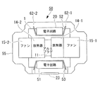
図7は、放射性物質可視化カメラの実施の他の形態を示している。その放射性物質可視化カメラ50は、既述の実施の形態における放射性物質可視化カメラ10のケース3が他のケース55に置換されている。ケース55は、ケース3と同様にして、第1吸気口21−1と第2吸気口21−2と背面排気口22と下面吸気口23と第1下面排気口24−1と第2下面排気口24−2とが形成されている。ケース55は、第1上面排気口56−1と第2上面排気口56−2とがさらに形成されている。
FIG. 7 shows another embodiment of the radioactive substance visualization camera. In the radioactive
放射性物質可視化カメラ50は、図8に示されるように、電気機器51をさらに備えている。電気機器51は、冷却装置2の鉛直下側に配置されている。電気機器51は、水滴が接触しても適切に動作するように、防水対策が施されている。電気機器51は、電気機器20とともに、撮像用センサ6と第1ペルチェ冷却器12−1と第2ペルチェ冷却器12−2と第1ファン15−1と第2ファン15−2とを制御する。このとき、電気機器20は、電気機器51と同様にして、水滴が接触しても適切に動作するように、防水対策が施されている。
As shown in FIG. 8, the radioactive
放射性物質可視化カメラ50は、さらに、既述の実施の形態における放射性物質可視化カメラ10の仕切り板35と仕切り板36とが他の仕切り板52、53に置換されている。仕切り板52は、屈曲した板に形成されている。仕切り板52は、ケース3の内部に配置され、電気機器20と冷却装置2との間に配置されている。仕切り板53は、屈曲した板に形成されている。仕切り板53は、ケース3の内部に配置され、電気機器51と冷却装置2との間に配置されている。
In the radioactive
仕切り板52は、図9に示されるように、ケース55とともに、第1上方ペルチェ冷却系流路61−1と第2上方ペルチェ冷却系流路61−2と第1上方合流部62−1と第2上方合流部62−2と上方筐体内部冷却系流路63とを形成している。第1上方ペルチェ冷却系流路61−1は、第1放熱器14−1に接触した空気を第1上面排気口56−1から排気する。第2上方ペルチェ冷却系流路61−2は、第2放熱器14−2に接触した空気を第2上面排気口56−2から排気する。
9, the
第1上方合流部62−1は、第1上方ペルチェ冷却系流路61−1の途中に形成され、第1放熱器14−1から第1上面排気口56−1までの間に形成されている。第2上方合流部62−2は、第2上方ペルチェ冷却系流路61−2の途中に形成され、第2放熱器14−2から第2上面排気口56−2までの間に形成されている。 The first upper junction 62-1 is formed in the middle of the first upper Peltier cooling system flow path 61-1, and is formed between the first radiator 14-1 and the first upper surface exhaust port 56-1. Yes. The second upper junction 62-2 is formed in the middle of the second upper Peltier cooling system flow path 61-2, and is formed between the second radiator 14-2 and the second upper surface exhaust port 56-2. Yes.
上方筐体内部冷却系流路63は、センサモジュール1とケース55との間に形成され、電気機器20とケース55との間に形成されている。上方筐体内部冷却系流路63は、下面吸気口23に接続され、第1上方合流部62−1と第2上方合流部62−2とに接続されている。
The upper housing internal cooling
このとき、第1上方合流部62−1は、第1上方ペルチェ冷却系流路61−1に空気が流れることにより、空気を上方筐体内部冷却系流路63から第1上方ペルチェ冷却系流路61−1に吸引する。すなわち、第1上方合流部62−1は、第1上方ペルチェ冷却系流路61−1を空気が流れているときに、第1上方ペルチェ冷却系流路61−1を流れる空気の流れを用いて、空気を上方筐体内部冷却系流路63から第1上方ペルチェ冷却系流路61−1に吸引する。第2上方合流部62−2は、第2上方ペルチェ冷却系流路61−2に空気が流れることにより、空気を上方筐体内部冷却系流路63から第2上方ペルチェ冷却系流路61−2に吸引する。すなわち、第2上方合流部62−2は、第2上方ペルチェ冷却系流路61−2を空気が流れているときに、第2上方ペルチェ冷却系流路61−2を流れる空気の流れを用いて、空気を上方筐体内部冷却系流路63から第2上方ペルチェ冷却系流路61−2に吸引する。
At this time, the first upper merging section 62-1 causes the air to flow from the upper casing internal cooling
仕切り板53は、図10に示されるように、ケース55とともに、下方筐体内部冷却系流路64を形成し、仕切り板52と同様にして、図示されていない第1下方ペルチェ冷却系流路と第2下方ペルチェ冷却系流路と第1下方合流部と第2下方合流部とを形成している。その第1下方ペルチェ冷却系流路は、第1放熱器14−1に接触した空気を第1下面排気口24−1から排気する。その第2下方ペルチェ冷却系流路は、第2放熱器14−2に接触した空気を第2下面排気口24−2から排気する。
As shown in FIG. 10, the
その第1下方合流部は、その第1下方ペルチェ冷却系流路の途中に形成され、第1放熱器14−1から第1下面排気口24−1までの間に形成されている。その第2下方合流部は、その第2下方ペルチェ冷却系流路の途中に形成され、第2放熱器14−2から第2下面排気口24−2までの間に形成されている。 The first lower joining portion is formed in the middle of the first lower Peltier cooling system flow path, and is formed between the first radiator 14-1 and the first lower surface exhaust port 24-1. The second lower junction is formed in the middle of the second lower Peltier cooling system flow path, and is formed between the second radiator 14-2 and the second lower surface exhaust port 24-2.
下方筐体内部冷却系流路64は、センサモジュール1とケース55との間に形成され、電気機器51とケース55との間に形成されている。下方筐体内部冷却系流路64は、下面吸気口23に接続され、その第1下方合流部とその第2下方合流部とに接続されている。
The lower housing internal cooling
このとき、その第1下方合流部は、その第1下方ペルチェ冷却系流路に空気が流れることにより、空気を下方筐体内部冷却系流路64からその第1下方ペルチェ冷却系流路に吸引する。すなわち、その第1下方合流部は、その第1下方ペルチェ冷却系流路を空気が流れているときに、その第1下方ペルチェ冷却系流路を流れる空気の流れを用いて、空気を下方筐体内部冷却系流路64からその第1下方ペルチェ冷却系流路に吸引する。その第2下方合流部は、その第2下方ペルチェ冷却系流路に空気が流れることにより、空気を下方筐体内部冷却系流路64からその第2下方ペルチェ冷却系流路に吸引する。すなわち、その第2下方合流部は、その第2下方ペルチェ冷却系流路を空気が流れているときに、その第2下方ペルチェ冷却系流路を流れる空気の流れを用いて、空気を下方筐体内部冷却系流路64からその第2下方ペルチェ冷却系流路に吸引する。
At this time, the first lower merging portion sucks air from the lower housing internal cooling
仕切り板52と仕切り板53は、図11に示されるように、ケース55とともに後方ペルチェ冷却系流路65を形成している。後方ペルチェ冷却系流路65は、既述の実施の形態における後方ペルチェ冷却系流路41と同様にして、第1放熱器14−1に接触した空気と第2放熱器14−2に接触した空気とを背面排気口22から排気する。
As shown in FIG. 11, the
仕切り板52は、さらに、ケース55とともに上方合流部66を形成している。上方合流部66は、後方ペルチェ冷却系流路65の途中に形成され、第1放熱器14−1および第2放熱器14−2から背面排気口22までの間に形成されている。上方合流部66は、上方筐体内部冷却系流路63に接続されている。このとき、上方合流部66は、後方ペルチェ冷却系流路65に空気が流れることにより、空気を上方筐体内部冷却系流路63から後方ペルチェ冷却系流路65に吸引する。すなわち、上方合流部66は、後方ペルチェ冷却系流路65を空気が流れているときに、後方ペルチェ冷却系流路65を流れる空気の流れを用いて、空気を上方筐体内部冷却系流路63から後方ペルチェ冷却系流路65に吸引する。
The
仕切り板52は、さらに、ケース55とともに下方合流部67を形成している。下方合流部67は、後方ペルチェ冷却系流路65の途中に形成され、第1放熱器14−1および第2放熱器14−2から背面排気口22までの間に形成されている。下方合流部67は、上方筐体内部冷却系流路63に接続されている。このとき、下方合流部67は、後方ペルチェ冷却系流路65に空気が流れることにより、空気を上方筐体内部冷却系流路63から後方ペルチェ冷却系流路65に吸引する。すなわち、下方合流部67は、後方ペルチェ冷却系流路65を空気が流れているときに、後方ペルチェ冷却系流路65を流れる空気の流れを用いて、空気を上方筐体内部冷却系流路63から後方ペルチェ冷却系流路65に吸引する。
The
放射性物質可視化カメラ50は、既述の実施の形態における放射性物質可視化カメラ10と概ね同様にして動作する。すなわち、電気機器20と電気機器51とは、第1ファン15−1を制御することにより、第1吸気口21−1から吸気された空気を第1放熱器14−1に向けて送風し、第2ファン15−2を制御することにより、第2吸気口21−2から吸気された空気を第2放熱器14−2に向けて送風する。第1放熱器14−1は、第1ファン15−1により送風されることにより、冷却される。第2放熱器14−2は、第2ファン15−2により送風されることにより、冷却される。
The radioactive
電気機器20と電気機器51とは、さらに、第1ペルチェ冷却器12−1を制御することにより、アルミプラグ11から第1放熱器14−1に熱を移動させ、第2ペルチェ冷却器12−2を制御することにより、アルミプラグ11から第2放熱器14−2に熱を移動させる。アルミプラグ11は、このような動作により冷却される。撮像用センサ6は、アルミプラグ11が冷却されることにより、冷却される。
The
第1上方合流部62−1と第2上方合流部62−2と上方合流部66とは、第1ファン15−1と第2ファン15−2とが送風することにより、上方筐体内部冷却系流路63から第1上方ペルチェ冷却系流路61−1と第2上方ペルチェ冷却系流路61−2と後方ペルチェ冷却系流路65とに空気を吸引する。上方筐体内部冷却系流路63は、第1上方合流部62−1と第2上方合流部62−2と上方合流部66とにより空気が吸引されることにより、空気が流れる。放射性物質可視化カメラ50は、上方筐体内部冷却系流路63に空気が流れることにより、電気機器20を冷却し、ケース55からセンサモジュール1に伝熱する熱量を低減する。
The first upper merging section 62-1, the second upper merging section 62-2 and the
その第1下方合流部と第2下方合流部と下方合流部67とは、第1ファン15−1と第2ファン15−2とが送風することにより、下方筐体内部冷却系流路64から第1下方ペルチェ冷却系流路42−1と第2下方ペルチェ冷却系流路42−2と後方ペルチェ冷却系流路65とに空気を吸引する。下方筐体内部冷却系流路64は、その第1下方合流部と第2下方合流部と下方合流部67とにより空気が吸引されることにより、空気が流れる。放射性物質可視化カメラ50は、下方筐体内部冷却系流路64に空気が流れることにより、電気機器51を冷却し、ケース55からセンサモジュール1に伝熱する熱量を低減する。
The first lower merging portion, the second lower merging portion, and the
電気機器20と電気機器51とは、撮像用センサ6が冷却されているときに、既述の実施の形態における放射性物質可視化カメラ10の電気機器20と同様にして、撮像用センサ6を制御することにより、放射線データを測定する。
The
このような放射性物質可視化カメラ50は、既述の実施の形態における放射性物質可視化カメラ10と同様にして、電気機器20と電気機器51とが過熱することが防止され、ケース3からセンサモジュール1に伝熱する熱量を低減し、放射線データを適切に測定することができる。
Such a radioactive
放射性物質可視化カメラ50は、さらに、第1ファン15−1と第2ファン15−2とにより生成される空気の流れを用いて上方筐体内部冷却系流路63と下方筐体内部冷却系流路64とに空気を流すことができる。このため、放射性物質可視化カメラ50は、上方筐体内部冷却系流路63と下方筐体内部冷却系流路64とに空気を送風するファンを備える他の放射性物質可視化カメラに比較して、より軽量に、より小型に形成されることができる。
The radioactive
放射性物質可視化カメラ50は、アルミプラグ11が冷却されることにより、アルミプラグ11の周辺が結露し、その結露した水滴が落下することがある。電気機器51は、防水対策が施されていることにより、その結露した水滴が接触した場合でも、適切に動作することができる。放射性物質可視化カメラ50は、屋外で使用されるときに、ケース3に形成される孔から雨滴が浸入することがある。電気機器20は、防水対策が施されていることにより、その浸入した雨滴が接触した場合でも、適切に動作することができる。
In the radioactive
既述の実施の形態における放射性物質可視化カメラ10は、電気機器20がアルミプラグ11の鉛直上側に配置されていることにより、アルミプラグ11の周辺に結露した水滴が電気機器20に接触し難く、電気機器20に施す防水対策の程度を低減することができる。既述の実施の形態における放射性物質可視化カメラ10の電気機器20は、電気機器20に施す防水対策の程度を低減することにより、電気機器51に比較して、より容易に作製されることができる。
In the radioactive
既述の実施の形態における放射性物質可視化カメラ10は、さらに、ケース3の上面に孔が形成されていないことにより、ケース3の内部に雨滴が浸入し難く、電気機器20に施す防水対策の程度を低減することができる。既述の実施の形態における放射性物質可視化カメラ10は、電気機器20に施す防水対策の程度を低減することにより、放射性物質可視化カメラ50に比較して、より容易に作製されることができる。
In the radioactive
1 :センサモジュール
2 :冷却装置
3 :ケース
10:放射性物質可視化カメラ
11:アルミプラグ
12−1:第1ペルチェ冷却器
12−2:第2ペルチェ冷却器
14−1:第1放熱器
14−2:第2放熱器
15−1:第1ファン
15−2:第2ファン
20:電気機器
21−1:第1吸気口
21−2:第2吸気口
22:背面排気口
23:下面吸気口
24−1:第1下面排気口
24−2:第2下面排気口
35:仕切り板
36:仕切り板
41:後方ペルチェ冷却系流路
42−1:第1下方ペルチェ冷却系流路
42−2:第2下方ペルチェ冷却系流路
43:筐体内部冷却系流路
44:合流部
50:放射性物質可視化カメラ
51:電気機器
52:仕切り板
53:仕切り板
55:ケース
56−1:第1上面排気口
56−2:第2上面排気口
61−1:第1上方ペルチェ冷却系流路
61−2:第2上方ペルチェ冷却系流路
62−1:第1上方合流部
62−2:第2上方合流部
63:上方筐体内部冷却系流路
64:下方筐体内部冷却系流路
65:後方ペルチェ冷却系流路
66:上方合流部
67:下方合流部
1: Sensor module 2: Cooling device 3: Case 10: Radioactive substance visualization camera 11: Aluminum plug 12-1: First Peltier cooler 12-2: Second Peltier cooler 14-1: First radiator 14-2 : 2nd radiator 15-1: 1st fan 15-2: 2nd fan 20: Electrical equipment 21-1: 1st inlet 21-2: 2nd inlet 22: Back exhaust 23: Bottom inlet 24 -1: First lower surface exhaust port 24-2: Second lower surface exhaust port 35: Partition plate 36: Partition plate 41: Rear Peltier cooling system flow path 42-1: First lower Peltier cooling system flow path 42-2: First 2 Lower Peltier cooling system flow path 43: Housing internal cooling system flow path 44: Junction section 50: Radioactive substance visualization camera 51: Electric equipment 52: Partition plate 53: Partition plate 55: Case 56-1: First upper surface exhaust port 56-2: Second top Surface exhaust port 61-1: First upper Peltier cooling system flow path 61-2: Second upper Peltier cooling system flow path 62-1: First upper merging section 62-2: Second upper merging section 63: Upper casing Internal cooling system flow path 64: Lower housing internal cooling system flow path 65: Rear Peltier cooling system flow path 66: Upper merging section 67: Lower merging section
Claims (5)
前記センサモジュールを冷却することにより生成される熱を放熱する放熱部と、
前記センサモジュールと異なる発熱部と、
前記放熱部を冷却する第1流体の流れを生成するファンと、
ケースとを備え、
前記ケースは、
前記第1流体が流れる第1流路と、
前記発熱部を冷却する第2流体が流れる第2流路と、
前記第1流路と前記第2流路とを隔てる仕切板と、
前記第1流体の流れを用いて前記第2流路から前記第1流路に前記第2流体を吸引する合流部とを形成するカメラ。 A sensor module that measures radiation data that visualizes the distribution of radioactive materials by receiving radiation; and
A heat dissipating part for dissipating heat generated by cooling the sensor module;
A heat generating part different from the sensor module;
A fan that generates a flow of a first fluid that cools the heat dissipating unit;
With a case,
The case is
A first flow path through which the first fluid flows;
A second flow path through which a second fluid for cooling the heat generating part flows;
A partition plate separating the first flow path and the second flow path;
The camera which forms the confluence | merging part which attracts | sucks the said 2nd fluid from the said 2nd flow path to the said 1st flow path using the flow of the said 1st fluid.
前記電気機器は、前記熱伝導部材より鉛直上側に配置されている請求項2に記載されるカメラ。 A heat conducting member in thermal contact with the sensor module;
The camera according to claim 2, wherein the electrical device is disposed vertically above the heat conducting member.
前記吸気口は、前記電気機器より鉛直下側に配置される請求項2〜請求項3のうちのいずれか一項に記載されるカメラ。 Wherein the case, the air inlet further formed to supply the second fluid from the exterior of the casing to the second passage,
The camera according to any one of claims 2 to 3, wherein the intake port is disposed vertically below the electric device.
Priority Applications (4)
| Application Number | Priority Date | Filing Date | Title |
|---|---|---|---|
| JP2013060229A JP6100048B2 (en) | 2013-03-22 | 2013-03-22 | camera |
| EP14767348.7A EP2950120B1 (en) | 2013-03-22 | 2014-02-27 | Radioactive substance visualization camera |
| PCT/JP2014/054934 WO2014148224A1 (en) | 2013-03-22 | 2014-02-27 | Camera |
| US14/771,072 US10070073B2 (en) | 2013-03-22 | 2014-02-27 | Camera for visualizing states of distribution of radioactive substances |
Applications Claiming Priority (1)
| Application Number | Priority Date | Filing Date | Title |
|---|---|---|---|
| JP2013060229A JP6100048B2 (en) | 2013-03-22 | 2013-03-22 | camera |
Publications (3)
| Publication Number | Publication Date |
|---|---|
| JP2014185909A JP2014185909A (en) | 2014-10-02 |
| JP2014185909A5 JP2014185909A5 (en) | 2016-04-21 |
| JP6100048B2 true JP6100048B2 (en) | 2017-03-22 |
Family
ID=51579915
Family Applications (1)
| Application Number | Title | Priority Date | Filing Date |
|---|---|---|---|
| JP2013060229A Active JP6100048B2 (en) | 2013-03-22 | 2013-03-22 | camera |
Country Status (4)
| Country | Link |
|---|---|
| US (1) | US10070073B2 (en) |
| EP (1) | EP2950120B1 (en) |
| JP (1) | JP6100048B2 (en) |
| WO (1) | WO2014148224A1 (en) |
Families Citing this family (3)
| Publication number | Priority date | Publication date | Assignee | Title |
|---|---|---|---|---|
| DE202018101447U1 (en) | 2018-03-15 | 2019-06-18 | Occhio GmbH | lighting device |
| TWI678548B (en) * | 2018-10-16 | 2019-12-01 | 國家中山科學研究院 | Monitoring distance measuring device heat dissipation structure |
| CN113678059B (en) * | 2020-06-30 | 2023-05-16 | 深圳市大疆创新科技有限公司 | Tripod head camera and shell and movable platform thereof |
Family Cites Families (11)
| Publication number | Priority date | Publication date | Assignee | Title |
|---|---|---|---|---|
| US4319755A (en) | 1980-10-31 | 1982-03-16 | Orser Sr Garry D | Tossing game |
| JPS623742Y2 (en) * | 1981-04-27 | 1987-01-28 | ||
| JP2000111083A (en) | 1998-09-30 | 2000-04-18 | Fujitsu General Ltd | Air conditioner |
| JP4138107B2 (en) | 1998-11-04 | 2008-08-20 | 浜松ホトニクス株式会社 | Radiation detector |
| JP2002071811A (en) * | 2000-09-01 | 2002-03-12 | Japan Science & Technology Corp | Measuring method and its device by luminescence combined with small x-ray irradiation means for accumulating radiation |
| US7065173B2 (en) * | 2003-12-02 | 2006-06-20 | General Electric Company | Method and apparatus for thermal management of CT electronics |
| JP4503415B2 (en) * | 2004-10-26 | 2010-07-14 | 池上通信機株式会社 | Video camera equipment |
| JP3942188B2 (en) * | 2005-09-30 | 2007-07-11 | 株式会社日立製作所 | Nuclear medicine diagnostic device, positron emission tomography device and detector unit |
| US7732780B2 (en) * | 2006-05-22 | 2010-06-08 | Digirad Corporation | Combined cold plate and radiation shield |
| JP5042757B2 (en) * | 2007-09-21 | 2012-10-03 | 富士フイルム株式会社 | Radiation imaging equipment |
| JP5451265B2 (en) | 2009-08-31 | 2014-03-26 | キヤノン株式会社 | Radiography equipment |
-
2013
- 2013-03-22 JP JP2013060229A patent/JP6100048B2/en active Active
-
2014
- 2014-02-27 US US14/771,072 patent/US10070073B2/en active Active
- 2014-02-27 EP EP14767348.7A patent/EP2950120B1/en active Active
- 2014-02-27 WO PCT/JP2014/054934 patent/WO2014148224A1/en active Application Filing
Also Published As
| Publication number | Publication date |
|---|---|
| EP2950120B1 (en) | 2019-09-04 |
| EP2950120A4 (en) | 2016-03-16 |
| US10070073B2 (en) | 2018-09-04 |
| WO2014148224A1 (en) | 2014-09-25 |
| EP2950120A1 (en) | 2015-12-02 |
| JP2014185909A (en) | 2014-10-02 |
| US20160006952A1 (en) | 2016-01-07 |
Similar Documents
| Publication | Publication Date | Title |
|---|---|---|
| US8289715B2 (en) | Plasma display device | |
| JP6307884B2 (en) | Electronics | |
| JP2006210863A (en) | Wafer type heat dissipation module and its heat dissipation method | |
| JP2013013513A (en) | Radiographic image capture device, battery unit, electricity supply unit, radiographic image capture system and program | |
| KR20160139094A (en) | Closed cabinet for electric device having heat pipe | |
| US10795241B2 (en) | IP camera with heat-conducting element for preventing dew condensation | |
| JP6100048B2 (en) | camera | |
| JP2009231511A (en) | Casing | |
| KR20190068486A (en) | A cooling apparatus for electronic elements | |
| JP5649369B2 (en) | Electronics | |
| JP2015126128A (en) | Electronic apparatus having forced air cooling | |
| TWM512123U (en) | Liquid cooling apparatus and system | |
| JP6159783B2 (en) | Electronics | |
| CN110632811A (en) | Projector with a light source | |
| JP4954625B2 (en) | Surveillance camera | |
| CN206311212U (en) | A kind of thermal infrared imager | |
| JP2019091884A (en) | Electronic apparatus | |
| JP2012204983A (en) | Full-perimeter camera | |
| JP2011204715A (en) | Radiation unit and electronic device using the same | |
| JP5829430B2 (en) | Imaging device | |
| JP2014185909A5 (en) | ||
| JP4840675B2 (en) | Video camera with cooling function | |
| US11369259B2 (en) | Endoscopic device and heat radiator | |
| JP2007274565A (en) | Imaging apparatus | |
| TWI556716B (en) | Heat exchange unit, heat exchange device and closed electrical apparatus with heat exchange device |
Legal Events
| Date | Code | Title | Description |
|---|---|---|---|
| A521 | Request for written amendment filed |
Free format text: JAPANESE INTERMEDIATE CODE: A523 Effective date: 20160308 |
|
| A621 | Written request for application examination |
Free format text: JAPANESE INTERMEDIATE CODE: A621 Effective date: 20160308 |
|
| TRDD | Decision of grant or rejection written | ||
| A01 | Written decision to grant a patent or to grant a registration (utility model) |
Free format text: JAPANESE INTERMEDIATE CODE: A01 Effective date: 20170124 |
|
| A61 | First payment of annual fees (during grant procedure) |
Free format text: JAPANESE INTERMEDIATE CODE: A61 Effective date: 20170222 |
|
| R150 | Certificate of patent or registration of utility model |
Ref document number: 6100048 Country of ref document: JP Free format text: JAPANESE INTERMEDIATE CODE: R150 |