EP2950120B1 - Radioactive substance visualization camera - Google Patents
Radioactive substance visualization camera Download PDFInfo
- Publication number
- EP2950120B1 EP2950120B1 EP14767348.7A EP14767348A EP2950120B1 EP 2950120 B1 EP2950120 B1 EP 2950120B1 EP 14767348 A EP14767348 A EP 14767348A EP 2950120 B1 EP2950120 B1 EP 2950120B1
- Authority
- EP
- European Patent Office
- Prior art keywords
- radiator
- cooling passage
- fan
- air
- case
- Prior art date
- Legal status (The legal status is an assumption and is not a legal conclusion. Google has not performed a legal analysis and makes no representation as to the accuracy of the status listed.)
- Active
Links
Images


Classifications
-
- G—PHYSICS
- G01—MEASURING; TESTING
- G01T—MEASUREMENT OF NUCLEAR OR X-RADIATION
- G01T1/00—Measuring X-radiation, gamma radiation, corpuscular radiation, or cosmic radiation
- G01T1/29—Measurement performed on radiation beams, e.g. position or section of the beam; Measurement of spatial distribution of radiation
- G01T1/2914—Measurement of spatial distribution of radiation
- G01T1/2921—Static instruments for imaging the distribution of radioactivity in one or two dimensions; Radio-isotope cameras
-
- H—ELECTRICITY
- H04—ELECTRIC COMMUNICATION TECHNIQUE
- H04N—PICTORIAL COMMUNICATION, e.g. TELEVISION
- H04N5/00—Details of television systems
- H04N5/30—Transforming light or analogous information into electric information
- H04N5/33—Transforming infrared radiation
-
- G—PHYSICS
- G01—MEASURING; TESTING
- G01T—MEASUREMENT OF NUCLEAR OR X-RADIATION
- G01T7/00—Details of radiation-measuring instruments
Definitions
- the present invention relates to a camera, and more particularly to a camera which is used for visualizing states of distribution of radioactive substances.
- Radioactive substance visualization cameras are known which visualize states of distribution of radioactive substances.
- the radioactive substance visualization camera is equipped with a cooling device and a sensor module.
- the cooling device cools the sensor module. While being cooled at a predetermined temperature or lower, the sensor module measures radiation data which shows a state of distribution of radioactive substances.
- JP 4138107 B discloses a radiation detector which measures radiation including X-rays and gamma rays. This radiation detector achieves an improved signal-noise ratio by cooling a semiconductor radiation detecting element by means of an electronic cooling element.
- EP 1780557 A1 discloses a positron emission computed tomography (PET) apparatus with a detector unit located in a casing of the apparatus.
- a plurality of air intake fans are arranged at one side of the detector units and a plurality of exhaust fans are located at another side of the detector units which is oriented in a direction that is perpendicular to the direction of air flow produced by the air intake fans.
- US 2005/0117698 A1 discloses a method and an apparatus for thermal management of computed tomography (CT) electronics.
- a fan is located at an outlet of a respective detector unit and is accordingly provided to forcibly discharge the air from a casing to the outside.
- thermoelectric cooling elements for the visualisation of a distribution of radiation comprising thermoelectric cooling elements and a cold plate for simultaneous cooling of the active elements of the camera and electromagnetic shielding.
- radioactive substance visualization cameras include a heat generation part, which generates heat, separately from the sensor module. It is desired that the heat generation part of such a radioactive substance visualization camera be cooled and at the same time as the camera is made compact.
- An object of the present invention is to provide a compact camera.
- a camera includes the features of claim 1 comprising inter alia: a sensor module which, on exposure to radiation, measures radiation data for visualizing a state of distribution of radioactive substances; a heat radiation part which radiates heat generated as the sensor module is cooled; a heat generation part which is different from the sensor module; a fan which generates a flow of a first fluid for cooling the heat radiation part; and a case.
- the case forms a first passage through which the first fluid flows, a second passage through which a second fluid for cooling the heat generation part flows, and a merging part which sucks the second fluid from the second passage into the first passage by means of the flow of the first fluid.
- Such a camera can adequately cool both of the sensor module and the heat generation part by means of the first fluid and the second fluid, and can adequately measure the radiation data. Moreover, such a camera can be made more lightweight than other cameras which further include a fan for circulating the second fluid through the second passage.
- the heat generation part is an electrical apparatus which controls the sensor module. Such a camera can make the sensor module work more properly by adequately cooling the electronic apparatus.
- the camera according to the present invention further includes a heat conducting member which comes into thermal contact with the sensor module.
- the electrical apparatus may be disposed further on a vertically upper side than the heat conducting member. In such a camera, water droplets formed by condensation on the heat conducting member are unlikely to come into contact with the electrical apparatus, and negative effects of the water droplets on the electrical apparatus can be reduced.
- the case may further have an air intake opening for supplying the first fluid to the second fluid.
- the air intake opening is disposed further on a vertically lower side than the electrical apparatus. In such a camera, water droplets entering through the air intake opening are unlikely to come into contact with the electrical apparatus, and negative effects of the water droplets on the electrical apparatus can be reduced.
- the second passage may be formed such that the second fluid flows through a periphery of the sensor module. In such a camera, conduction of heat from outside to the sensor module is reduced, so that the sensor module can be cooled adequately.
- the camera according to the present invention can adequately cool both of the sensor module and the heat generation part, and at the same time can be made more lightweight than other cameras which further include a fan for cooling the heat generation part.
- a radioactive substance visualization camera 10 includes a sensor module 1, a cooling device 2, and a case 3.
- the sensor module 1 includes a sensor case 5, an imaging sensor 6, and a heat insulation material 7.
- the sensor case 5 is formed as a case which seals the inside.
- the imaging sensor 6 is disposed inside the sensor case 5. While being exposed to radiation emitted from radioactive substances, the imaging sensor 6 is controlled by an electrical apparatus, to be described later, so as to measure radiation data for visualizing the state of distribution of the radioactive substances.
- the radiation data shows a plurality of directions and a plurality of pieces of radioactivity data corresponding to the plurality of directions.
- a piece of radioactivity data corresponding to a certain direction shows the nuclide of the radioactive substance disposed in that direction from the radioactive substance visualization camera 10, and shows the amount of substance of the nuclide.
- the heat insulation material 7 is formed of a material having a heat conductivity lower than the heat conductivity of a material forming the sensor case 5.
- the heat insulation material 7 covers the sensor case 5.
- the sensor module 1 has the imaging sensor 6 disposed in a closed space sealed by the sensor case 5 and thereby prevents dew condensation on the imaging sensor 6.
- the sensor module 1 has the sensor case 5 covered with the heat insulation material 7 and thereby prevents heat from the outside of the radioactive substance visualization camera 10 from being conducted to the imaging sensor 6.
- the cooling device 2 includes an aluminum plug 11, a first Peltier cooler 12-1, a first radiator 14-1, and a first fan 15-1.
- the aluminum plug 11 is formed of metal aluminum.
- the aluminum plug 11 is formed of an inner portion and an outer portion, and the inner portion and the outer portion are in thermal contact with each other.
- the inner portion is disposed inside the sensor case 5, and is in thermal contact with the sensor module 1.
- the outer portion is disposed outside the sensor case 5.
- the first Peltier cooler 12-1 includes a Peltier element.
- the first Peltier cooler 12-1 is disposed between the aluminum plug 11 and the first radiator 14-1, and is disposed so as to intersect a first straight line 16-1 connecting the aluminum plug 11 and the first radiator 14-1.
- the first Peltier cooler 12-1 is in thermal contact with the aluminum plug 11.
- the first Peltier cooler 12-1 is controlled by the electrical apparatus, to be described later, so as to transfer heat from the first aluminum plug 11 to the first radiator 14-1 by means of the Peltier element. That is, the first Peltier cooler 12-1 heats the first radiator 14-1 and cools the aluminum plug 11.
- the first radiator 14-1 is disposed so as to intersect the first straight line 16-1 and such that the first Peltier cooler 12-1 is disposed between the aluminum plug 11 and the first radiator 14-1.
- the first radiator 14-1 is in thermal contact with the first Peltier cooler 12-1.
- the first radiator 14-1 has a plurality of fins formed on the side opposite to the side in contact with the first Peltier cooler 12-1.
- the first fan 15-1 is disposed so as to intersect the first straight line 16-1 and such that the first radiator 14-1 is disposed between the first fan 15-1 and the first Peltier cooler 12-1.
- the first fan 15-1 is controlled by the electrical apparatus, to be described later, so as to send outside air toward the plurality of fins formed on the first radiator 14-1.
- the cooling device 2 further includes a second Peltier cooler 12-2, a second radiator 14-2, and a second fan 15-2.
- the second Peltier cooler 12-2 includes a Peltier element.
- the second Peltier cooler 12-2 is disposed between the aluminum plug 11 and the second radiator 14-2, and is disposed so as to intersect a second straight line 16-2 connecting the aluminum plug 11 and the second radiator 14-2.
- the second Peltier cooler 12-2 is further in thermal contact with the aluminum plug 11.
- the second Peltier cooler 12-2 is controlled by the electrical apparatus, to be described later, so as to transfer heat from the aluminum plug 11 to the second radiator 14-2 by means of the Peltier element. That is, the second Peltier cooler 12-2 heats the second radiator 14-2 and cools the aluminum plug 11.
- the second radiator 14-2 is disposed so as to intersect the second straight line 16-2 and such that the second Peltier cooler 12-2 is disposed between the aluminum plug 11 and the second radiator 14-2.
- the second radiator 14-2 is in thermal contact with the second Peltier cooler 12-2.
- the second radiator 14-2 has a plurality of fins formed on the side opposite to the side in contact with the second Peltier cooler 12-2.
- the second fan 15-2 is disposed so as to intersect the second straight line 16-2 and such that the second radiator 14-2 is disposed between the second fan 15-2 and the second Peltier cooler 12-2.
- the second fan 15-2 is controlled by the electrical apparatus, to be described later, so as to send outside air toward the plurality of fins formed on the second radiator 14-2.
- the cooling device 2 is further formed such that the first straight line 16-1 and the second straight line 16-2 intersect with each other, and that the point at which the first straight line 16-1 and the second straight line 16-2 intersect with each other lies in the aluminum plug 11. That is, the distance from the center of the first radiator 14-1 to the center of the second radiator 14-2 is longer than the distance from the center of the first Peltier cooler 12-1 to the center of the second Peltier cooler 12-2. In this case, the first radiator 14-1 and the second radiator 14-2 can be made relatively large, and the area of their surfaces in contact with air can be made relatively large.
- the case 3 forms an outer shell of the radioactive substance visualization camera 10. That is, the sensor module 1 and the cooling device 2 are disposed inside the case 3.
- the radioactive substance visualization camera 10 further includes an electrical apparatus 20.
- the electrical apparatus 20 is disposed on the vertically upper side than the cooling device 2.
- the electrical apparatus 20 is electrically connected with the imaging sensor 6, and is connected so as to be able to transmit information.
- the electrical apparatus 20 supplies power to the imaging sensor 6, and controls the imaging sensor 6 such that radiation data for visualizing a state of distribution of radioactive substances is measured.
- the electrical apparatus 20 further supplies power to the first Peltier cooler 12-1 and the second Peltier cooler 12-2, and controls the first Peltier cooler 12-1 and the second Peltier cooler 12-2 such that the imaging sensor 6 is cooled.
- the electrical apparatus 20 further supplies power to the first fan 15-1 and the second fan 15-2, and controls the first fan 15-1 and the second fan 15-2 such that the first radiator 14-1 and the second radiator 14-2 are subjected to air.
- the case 3 has a first air intake opening 21-1, a second air intake opening 21-2, and a back-side air discharge opening 22 formed in the back surface.
- the case 3 further has a bottom-side air intake opening 23, a first bottom-side air discharge opening 24-1, and a second bottom-side air discharge opening 24-2 formed in the bottom surface.
- the first air intake opening 21-1 is formed so as to lie on the first straight line 16-1 and such that the first fan 15-1 is disposed between the first air intake opening 21-1 and the first radiator 14-1.
- the second air intake opening 21-2 is formed so as to lie on the second straight line 16-2 and such that the second fan 15-2 is disposed between the second air intake opening 21-2 and the second radiator 14-2.
- the first fan 15-1 suctions air from outside the case 3 through the first air intake opening 21-1 and sends the air to the first radiator 14-1.
- the second fan 15-2 suctions air from outside the case 3 through the second air intake opening 21-2 and sends the air to the second radiator 14-2.
- the radioactive substance visualization camera 10 further includes a partition plate 35.
- the partition plate 35 is formed as a plate.
- the partition plate 35 is disposed inside the case 3, and is disposed between the electrical apparatus 20 and the cooling device 2.
- the radioactive substance visualization camera 10 further includes a partition plate 36.
- the partition plate 36 is formed as a plate.
- the partition plate 36 is disposed inside the case 3.
- the rear Peltier cooling passage 41 discharges air having come into contact with the first radiator 14-1 and air having come into contact with the second radiator 14-2 from the back-side air discharge opening 22.
- the second lower Peltier cooling passage 42-2 discharges air having come into contact with the second radiator 14-2 from the second bottom-side air discharge opening 24-2.
- the first lower Peltier cooling passage 42-1 discharges air having come into contact with the first radiator 14-1 from the first bottom-side air discharge opening 24-1.
- the partition plate 35 and the partition plate 36, with the case 3, further form a casing internal cooling passage 43 and a merging part 44.
- the merging part 44 is formed on the midstream side of the rear Peltier cooling passage 41, and is formed from the first radiator 14-1 and the second radiator 14-2 to the back-side air discharge opening 22.
- the casing internal cooling passage 43 is formed between the sensor module 1 and the case 3, and is formed between the electrical apparatus 20 and the case 3.
- the casing internal cooling passage 43 is connected with the bottom-side air intake opening 23 and is connected with the merging part 44.
- the merging part 44 suctions air from the casing internal cooling passage 43 into the rear Peltier cooling passage 41. That is, while air is flowing through the rear Peltier cooling passage 41, the merging part 44 suctions air from the casing internal cooling passage 43 into the rear Peltier cooling passage 41 by means of the flow of the air flowing through the rear Peltier cooling passage 41.
- the aluminum plug 11 of such a radioactive substance visualization camera 10 can be made more compact, so that the camera can be made more compact, than other cameras of which the first straight line 16-1 and the second straight line 16-2 are parallel to each other.
- Actions of the radioactive substance visualization camera 10 include a cooling action and an imaging action.
- the cooling action is controlled by the electrical apparatus 20.
- the electrical apparatus 20 controls the first fan 15-1 to thereby send air suctioned through the first air intake opening 21-1 toward the first radiator 14-1, and controls the second fan 15-2 to thereby send air suctioned through the second air intake opening 21-2 toward the second radiator 14-2.
- the electrical apparatus 20 further controls the first Peltier cooler 12-1 to thereby transfer heat from the aluminum plug 11 to the first radiator 14-1, and controls the second Peltier cooler 12-2 to thereby transfer heat from the aluminum plug 11 to the second radiator 14-2.
- the aluminum plug 11 is cooled by the first Peltier cooler 12-1 and the second Peltier cooler 12-2. As the aluminum plug 11 is cooled, the imaging sensor 6 is cooled.
- the first radiator 14-1 is heated by the first Peltier cooler 12-1.
- the first radiator 14-1 is cooled on contact with air sent by the first fan 15-1.
- the second radiator 14-2 is cooled by the first fan 15-1 in the same manner as the first radiator 14-1.
- the first Peltier cooler 12-1 and the second Peltier cooler 12-2 can cool the imaging sensor 6 with high efficiency.
- the merging part 44 suctions air from the casing internal cooling passage 43 into the rear Peltier cooling passage 41 by means of the flow of the air flowing through the rear Peltier cooling passage 41.
- the casing internal cooling passage 43 suctions air through the bottom-side air intake opening 23, and circulates the air between the sensor module 1 and the case 3 and through the periphery of the electrical apparatus 20.
- the imaging action is performed while the cooling action is being performed.
- the electrical apparatus 20 supplies power to the imaging sensor 6 and controls the imaging sensor 6 to thereby measure radiation data.
- the radiation data shows a plurality of directions and a plurality of pieces of radioactivity data corresponding to the plurality of directions.
- a piece of radioactivity data corresponding to a certain direction shows the nuclide of the radioactive substance disposed in that direction from the radioactive substance visualization camera 10, and shows the amount of substance of the nuclide.
- the electrical apparatus 20 outputs the radiation data to an external apparatus.
- the radiation data is analyzed and thereby processed into a radioactive substance visualization image.
- the radioactive substance visualization image is formed of a plurality of regions corresponding to the plurality of directions. In a region corresponding to a certain direction of the plurality of regions, an image of an object disposed in that direction is projected, and a piece of radioactivity data of the plurality of pieces of radioactivity data corresponding to that direction is shown over the image of the object.
- Such a radioactive substance visualization image can display a state of distribution of radioactive substances in a manner that makes it more easily understandable.
- the electrical apparatus 20 is cooled and prevented from overheating as air flows through the casing internal cooling passage 43. Since overheating of the electrical apparatus 20 is prevented, the radioactive substance visualization camera 10 can adequately control the imaging sensor 6, the first Peltier cooler 12-1, the second Peltier cooler 12-2, the first fan 15-1, and the second fan 15-2. As the first Peltier cooler 12-1, the second Peltier cooler 12-2, the first fan 15-1, and the second fan 15-2 are adequately controlled, the radioactive substance visualization camera 10 can adequately cool the imaging sensor 6. As the imaging sensor 6 is adequately controlled, the radioactive substance visualization camera 10 can adequately measure radiation data.
- the case 3 may reach a high temperature due to exposure to sunlight. According to such a radioactive substance visualization camera 10, as air flows through the casing internal cooling passage 43, the amount of heat conducted from the case 3 is reduced, so that the sensor module 1 is prevented from being heated by sunlight. As the amount of heat conducted from the case 3 is reduced, the sensor module 1 can adequately cool the imaging sensor 6 and adequately measure radiation data.
- the radioactive substance visualization camera 10 uses the flow of air flowing through the rear Peltier cooling passage 41 to circulate air through the casing internal cooling passage 43, it can circulate air through the casing internal cooling passage 43 without using a fan for sending air to the casing internal cooling passage 43. Therefore, the radioactive substance visualization camera 10 can be made more lightweight and more compact than other radioactive substance visualization cameras which include a fan for sending air to the casing internal cooling passage 43.
- the radioactive substance visualization camera 10 As the aluminum plug 11 is cooled, dew condensation occurs in the periphery of the aluminum plug 11 and water droplets formed by the dew condensation may fall. In the radioactive substance visualization camera 10, since the electrical apparatus 20 is disposed further on the vertically upper side than the aluminum plug 11, water droplets formed by dew condensation are unlikely to come into contact with the electrical apparatus 20. Thus, the radioactive substance visualization camera 10 can reduce the negative effects of the water droplets on the electrical apparatus 20.
- the radioactive substance visualization camera 10 While the radioactive substance visualization camera 10 is being used outdoors, raindrops may enter through the holes formed in the case 3.
- the radioactive substance visualization camera 10 has the first air intake opening 21-1, the second air intake opening 21-2, the back-side air discharge opening 22, the bottom-side air intake opening 23, the first bottom-side air discharge opening 24-1, and the second bottom-side air discharge opening 24-2 formed in a region of the case 3 further on the vertically lower side than the electrical apparatus 20. Therefore, the radioactive substance visualization camera 10 can reduce the negative effects of raindrops entering through the holes formed in the case 3 on the electrical apparatus 20.
- the aluminum plug 11 can be substituted with a heat conducting member which is formed of a material other than metal aluminum.
- the material has a heat conductivity higher than the heat conductivity of the material forming the sensor case 5.
- the radioactive substance visualization camera including such a heat conducting member can also be made compact as with the radioactive substance visualization camera of the already-described embodiment.
- Fig. 7 shows another embodiment of the radioactive substance visualization camera.
- the case 3 of the radioactive substance visualization camera 10 of the already-described embodiment is substituted with another case 55.
- the case 55 has the first air intake opening 21-1, the second air intake opening 21-2, the back-side air discharge opening 22, the bottom-side air intake opening 23, the first bottom-side air discharge opening 24-1, and the second bottom-side air discharge opening 24-2.
- the case 55 further has a first top-side air discharge opening 56-1 and a second top-side air discharge opening 56-2.
- the radioactive substance visualization camera 50 further includes an electrical apparatus 51.
- the electrical apparatus 51 is disposed on the vertically lower side of the cooling device 2.
- the electrical apparatus 51 is provided with waterproofing measures so as to work properly even on contact with water droplets.
- the electrical apparatus 51 controls, with the electrical apparatus 20, the imaging sensor 6, the first Peltier cooler 12-1, the second Peltier cooler 12-2, the first fan 15-1, and the second fan 15-2.
- the electrical apparatus 20 is provided with waterproofing measures so as to work properly even on contact with water droplets.
- the partition plate 35 and the partition plate 36 of the radioactive substance visualization camera 10 of the already-described embodiment are also substituted with other partition plates 52, 53.
- the partition plate 52 is formed as a bent plate.
- the partition plate 52 is disposed inside the case 3 and is disposed between the electrical apparatus 20 and the cooling device 2.
- the partition plate 53 is formed as a bent plate.
- the partition plate 53 is disposed inside the case 3 and is disposed between the electrical apparatus 51 and the cooling device 2.
- the partition plate 52 forms a first upper Peltier cooling passage 61-1, a second upper Peltier cooling passage 61-2, a first upper merging part 62-1, a second upper merging part 62-2, and an upper casing internal cooling passage 63.
- the first upper Peltier cooling passage 61-1 discharges air having come into contact with the first radiator 14-1 from the first top-side air discharge opening 56-1.
- the second upper Peltier cooling passage 61-2 discharges air having come into contact with the second radiator 14-2 from the second top-side air discharge opening 56-2.
- the first upper merging part 62-1 is formed on the midstream side of the first upper Peltier cooling passage 61-1 and is formed from the first radiator 14-1 to the first top-side air discharge opening 56-1.
- the second upper merging part 62-2 is formed on the midstream side of the second upper Peltier cooling passage 61-2 and is formed from the second radiator 14-2 to the second top-side air discharge opening 56-2.
- the upper casing internal cooling passage 63 is formed between the sensor module 1 and the case 55 and is formed between the electrical apparatus 20 and the case 55.
- the upper casing internal cooling passage 63 is connected with the bottom-side air intake opening 23 and is connected with the first upper merging part 62-1 and the second upper merging part 62-2.
- the first upper merging part 62-1 suctions air from the upper casing internal cooling passage 63 into the first upper Peltier cooling passage 61-1. That is, when air is flowing through the first upper Peltier cooling passage 61-1, the first upper merging part 62-1 suctions air from the upper casing internal cooling passage 63 into the first upper Peltier cooling passage 61-1 by means of the flow of the air flowing through the first upper Peltier cooling passage 61-1.
- the second upper merging part 62-2 suctions air from the upper casing internal cooling passage 63 into the second upper Peltier cooling passage 61-2.
- the second upper merging part 62-2 suctions air from the upper casing internal cooling passage 63 into the second upper Peltier cooling passage 61-2 by means of the flow of the air flowing through the second upper Peltier cooling passage 61-2.
- the partition plate 53 As shown in Fig. 10 , the partition plate 53, with the case 55, forms a lower casing internal cooling passage 64, and as with the partition plate 52, forms the first lower Peltier cooling passage, the second lower Peltier cooling passage, a first lower merging part, and a second lower merging part (all not shown).
- the first lower Peltier cooling passage discharges air having come into contact with the first radiator 14-1 from the first bottom-side air discharge opening 24-1.
- the second lower Peltier cooling passage discharges air having come into contact with the second radiator 14-2 from the second bottom-side air discharge opening 24-2.
- the first lower merging part is formed on the midstream side of the first lower Peltier cooling passage and is formed from the first radiator 14-1 to the first bottom-side air discharge opening 24-1.
- the second lower merging part is formed on the midstream side of the second lower Peltier cooling passage and is formed from the second radiator 14-2 to the second bottom-side air discharge opening 24-2.
- the lower casing internal cooling passage 64 is formed between the sensor module 1 and the case 55 and is formed between the electrical apparatus 51 and the case 55.
- the lower casing internal cooling passage 64 is connected with the bottom-side air intake opening 23 and is connected with the first lower merging part and the second lower merging part.
- the first lower merging part suctions air from the lower casing internal cooling passage 64 into the first lower Peltier cooling passage. That is, when air is flowing through the first lower Peltier cooling passage, the first lower merging part suctions air from the lower casing internal cooling passage 64 into the first lower Peltier cooling passage by means of the flow of the air flowing through the first lower Peltier cooling passage.
- the second lower merging part suctions air from the lower casing internal cooling passage 64 into the second lower Peltier cooling passage. That is, when air is flowing through the second lower Peltier cooling passage, the second lower merging part suctions air from the lower casing internal cooling passage 64 into the second lower Peltier cooling passage by means of the flow of the air flowing through the second lower Peltier cooling passage.
- the rear Peltier cooling passage 65 discharges air having come into contact with the first radiator 14-1 and air having come into contact with the second radiator 14-2 from the back-side air discharge opening 22.
- the partition plate 52 with the case 55, further forms an upper merging part 66.
- the upper merging part 66 is formed on the midstream side of the rear Peltier cooling passage 65 and is formed from the first radiator 14-1 and the second radiator 14-2 to the back-side air discharge opening 22.
- the upper merging part 66 is connected with the upper casing internal cooling passage 63.
- the upper merging part 66 suctions air from the upper casing internal cooling passage 63 into the rear Peltier cooling passage 65. That is, when air is flowing through the rear Peltier cooling passage 65, the upper merging part 66 suctions air from the upper casing internal cooling passage 63 into the rear Peltier cooling passage 65 by means of the flow of the air flowing through the rear Peltier cooling passage 65.
- the partition plate 52 with the case 55, further forms a lower merging part 67.
- the lower merging part 67 is formed on the midstream side of the rear Peltier cooling passage 65 and is formed from the first radiator 14-1 and the second radiator 14-2 to the back-side air discharge opening 22.
- the lower merging part 67 is connected with the upper casing internal cooling passage 63.
- the lower merging part 67 suctions air from the upper casing internal cooling passage 63 into the rear Peltier cooling passage 65. That is, when air is flowing through the rear Peltier cooling passage 65, the lower merging part 67 suctions air from the upper casing internal cooling passage 63 into the rear Peltier cooling passage 65 by means of the flow of the air flowing through the rear Peltier cooling passage 65.
- the radioactive substance visualization camera 50 works almost in the same manner as the radioactive substance visualization camera 10 of the already-described embodiment. That is, the electrical apparatus 20 and the electrical apparatus 51 control the first fan 15-1 to thereby send air, suctioned through the first air intake opening 21-1, toward the first radiator 14-1, and control the second fan 15-2 to thereby send air, suctioned through the second air intake opening 21-2, toward the second radiator 14-2. As air is sent by the first fan 15-1 to the first radiator 14-1, the first radiator 14-1 is cooled. As air is sent by the second fan 15-2 to the second radiator 14-2, the second radiator 14-2 is cooled.
- the electrical apparatus 20 and the electrical apparatus 51 further control the first Peltier cooler 12-1 to thereby transfer heat from the aluminum plug 11 to the first radiator 14-1, and control the second Peltier cooler 12-2 to thereby transfer heat from the aluminum plug 11 to the second radiator 14-2.
- the aluminum plug 11 is cooled through these actions. As the aluminum plug 11 is cooled, the imaging sensor 6 is cooled.
- the first upper merging part 62-1, the second upper merging part 62-2, and the upper merging part 66 suction air from the upper casing internal cooling passage 63 into the first upper Peltier cooling passage 61-1, the second upper Peltier cooling passage 61-2, and the rear Peltier cooling passage 65.
- air is suctioned by the first upper merging part 62-1, the second upper merging part 62-2, and the upper merging part 66, air flows through the upper casing internal cooling passage 63.
- the radioactive substance visualization camera 50 cools the electrical apparatus 20 and reduces the amount of heat conducted from the case 55 to the sensor module 1.
- the first lower merging part, the second lower merging part, and the lower merging part 67 suction air from the lower casing internal cooling passage 64 into the first lower Peltier cooling passage 42-1, the second lower Peltier cooling passage 42-2, and the rear Peltier cooling passage 65.
- air is suctioned by the first lower merging part, the second lower merging part, and the lower merging part 67, air flows through the lower casing internal cooling passage 64.
- the radioactive substance visualization camera 50 cools the electrical apparatus 51 and reduces the amount of heat conducted from the case 55 to the sensor module 1.
- the electrical apparatus 20 and the electrical apparatus 51 control the imaging sensor 6 in the same manner as the electrical apparatus 20 of the radioactive substance visualization camera 10 of the already-described embodiment, to thereby measure radiation data.
- radioactive substance visualization camera 50 as with the radioactive substance visualization camera 10 of the already-described embodiment, overheating of the electrical apparatus 20 and the electrical apparatus 51 is prevented, and the amount of heat conducted from the case 3 to the sensor module 1 is reduced, so that radiation data can be measured adequately.
- the radioactive substance visualization camera 50 can circulate air through the upper casing internal cooling passage 63 and the lower casing internal cooling passage 64 by means of the flow of air generated by the first fan 15-1 and the second fan 15-2. Therefore, the radioactive substance visualization camera 50 can be made more lightweight and more compact than other radioactive substance visualization cameras which include a fan for sending air to the upper casing internal cooling passage 63 and the lower casing internal cooling passage 64.
- the radioactive substance visualization camera 50 As the aluminum plug 11 is cooled, dew condensation occurs in the periphery of the aluminum plug 11 and water droplets formed by the dew condensation may fall. Since the electrical apparatus 51 is provided with the waterproofing measures, it works properly even on contact with water droplets formed by dew condensation. While the radioactive substance visualization camera 50 is being used outdoors, raindrops may enter through the holes formed in the case 3. Since the electrical apparatus 20 is provided with the waterproofing measures, it works properly even on contact with entering raindrops.
- the electrical apparatus 20 since the electrical apparatus 20 is disposed on the vertically upper side of the aluminum plug 11, water droplets formed by dew condensation in the periphery of the aluminum plug 11 are unlikely to come into contact with the electrical apparatus 20, so that the level of waterproofing measures for the electrical apparatus 20 can be lowered. Since the level of waterproofing measures for the electrical apparatus 20 is lowered, the electrical apparatus 20 of the radioactive substance visualization camera 10 of the already-described embodiment can be produced more easily than the electrical apparatus 51.
- the radioactive substance visualization camera 10 of the already-described embodiment has no hole formed in the top surface of the case 3, water droplets are unlikely to enter the case 3, so that the level of waterproofing measures for the electrical apparatus 20 can be lowered. Since the level of waterproofing measures for the electrical apparatus 20 is lowered, the radioactive substance visualization camera 10 of the already-described embodiment can be produced more easily than the radioactive substance visualization camera 50.
Description
- The present invention relates to a camera, and more particularly to a camera which is used for visualizing states of distribution of radioactive substances.
- "Radioactive substance visualization cameras" are known which visualize states of distribution of radioactive substances. The radioactive substance visualization camera is equipped with a cooling device and a sensor module. The cooling device cools the sensor module. While being cooled at a predetermined temperature or lower, the sensor module measures radiation data which shows a state of distribution of radioactive substances.
-
JP 4138107 B -
EP 1780557 A1 discloses a positron emission computed tomography (PET) apparatus with a detector unit located in a casing of the apparatus. A plurality of air intake fans are arranged at one side of the detector units and a plurality of exhaust fans are located at another side of the detector units which is oriented in a direction that is perpendicular to the direction of air flow produced by the air intake fans. -
US 2005/0117698 A1 discloses a method and an apparatus for thermal management of computed tomography (CT) electronics. A fan is located at an outlet of a respective detector unit and is accordingly provided to forcibly discharge the air from a casing to the outside. - The document
US 2007/267577 A1 discloses a camera for the visualisation of a distribution of radiation comprising thermoelectric cooling elements and a cold plate for simultaneous cooling of the active elements of the camera and electromagnetic shielding. - Some radioactive substance visualization cameras include a heat generation part, which generates heat, separately from the sensor module. It is desired that the heat generation part of such a radioactive substance visualization camera be cooled and at the same time as the camera is made compact.
- An object of the present invention is to provide a compact camera.
- A camera according to the present invention includes the features of
claim 1 comprising inter alia: a sensor module which, on exposure to radiation, measures radiation data for visualizing a state of distribution of radioactive substances; a heat radiation part which radiates heat generated as the sensor module is cooled; a heat generation part which is different from the sensor module; a fan which generates a flow of a first fluid for cooling the heat radiation part; and a case. In this camera, the case forms a first passage through which the first fluid flows, a second passage through which a second fluid for cooling the heat generation part flows, and a merging part which sucks the second fluid from the second passage into the first passage by means of the flow of the first fluid. - Such a camera can adequately cool both of the sensor module and the heat generation part by means of the first fluid and the second fluid, and can adequately measure the radiation data. Moreover, such a camera can be made more lightweight than other cameras which further include a fan for circulating the second fluid through the second passage.
- The heat generation part is an electrical apparatus which controls the sensor module. Such a camera can make the sensor module work more properly by adequately cooling the electronic apparatus.
- The camera according to the present invention further includes a heat conducting member which comes into thermal contact with the sensor module. In this camera, the electrical apparatus may be disposed further on a vertically upper side than the heat conducting member. In such a camera, water droplets formed by condensation on the heat conducting member are unlikely to come into contact with the electrical apparatus, and negative effects of the water droplets on the electrical apparatus can be reduced.
- The case may further have an air intake opening for supplying the first fluid to the second fluid. The air intake opening is disposed further on a vertically lower side than the electrical apparatus. In such a camera, water droplets entering through the air intake opening are unlikely to come into contact with the electrical apparatus, and negative effects of the water droplets on the electrical apparatus can be reduced.
- The second passage may be formed such that the second fluid flows through a periphery of the sensor module. In such a camera, conduction of heat from outside to the sensor module is reduced, so that the sensor module can be cooled adequately.
- The camera according to the present invention can adequately cool both of the sensor module and the heat generation part, and at the same time can be made more lightweight than other cameras which further include a fan for cooling the heat generation part.
-
- {
Fig. 1} Fig. 1 is a sectional view showing an embodiment of a radioactive substance visualization camera. - {
Fig. 2} Fig. 2 is a transverse sectional view showing the embodiment of the radioactive substance visualization camera. - {
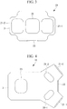
Fig. 3} Fig. 3 is a back view showing the embodiment of the radioactive substance visualization camera. - {
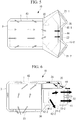
Fig. 4} Fig. 4 is a bottom view showing the embodiment of the radioactive substance visualization camera. - {
Fig. 5} Fig. 5 is a view through an upper surface showing the embodiment of the radioactive substance visualization camera. - {
Fig. 6} Fig. 6 is a view through a side surface showing the embodiment of the radioactive substance visualization camera. - {
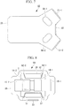
Fig. 7} Fig. 7 is a top view showing another embodiment of the radioactive substance visualization camera. - {
Fig. 8} Fig. 8 is a transverse sectional view showing the another embodiment of the radioactive substance visualization camera. - {
Fig. 9} Fig. 9 is a sectional view showing the another embodiment of the radioactive substance visualization camera. - {
Fig. 10} Fig. 10 is a vertical sectional view showing the another embodiment of the radioactive substance visualization camera. - {
Fig. 11} Fig. 11 is a vertical sectional view showing the another embodiment of the radioactive substance visualization camera. - Embodiments of a camera will be described below with reference to the drawings. As shown in
Fig. 1 , a radioactivesubstance visualization camera 10 includes asensor module 1, acooling device 2, and acase 3. Thesensor module 1 includes asensor case 5, animaging sensor 6, and aheat insulation material 7. - The
sensor case 5 is formed as a case which seals the inside. Theimaging sensor 6 is disposed inside thesensor case 5. While being exposed to radiation emitted from radioactive substances, theimaging sensor 6 is controlled by an electrical apparatus, to be described later, so as to measure radiation data for visualizing the state of distribution of the radioactive substances. The radiation data shows a plurality of directions and a plurality of pieces of radioactivity data corresponding to the plurality of directions. Of the plurality of pieces of radioactivity data, a piece of radioactivity data corresponding to a certain direction shows the nuclide of the radioactive substance disposed in that direction from the radioactivesubstance visualization camera 10, and shows the amount of substance of the nuclide. - The
heat insulation material 7 is formed of a material having a heat conductivity lower than the heat conductivity of a material forming thesensor case 5. Theheat insulation material 7 covers thesensor case 5. - The
sensor module 1 has theimaging sensor 6 disposed in a closed space sealed by thesensor case 5 and thereby prevents dew condensation on theimaging sensor 6. Thesensor module 1 has thesensor case 5 covered with theheat insulation material 7 and thereby prevents heat from the outside of the radioactivesubstance visualization camera 10 from being conducted to theimaging sensor 6. - The
cooling device 2 includes analuminum plug 11, a first Peltier cooler 12-1, a first radiator 14-1, and a first fan 15-1. Thealuminum plug 11 is formed of metal aluminum. Thealuminum plug 11 is formed of an inner portion and an outer portion, and the inner portion and the outer portion are in thermal contact with each other. The inner portion is disposed inside thesensor case 5, and is in thermal contact with thesensor module 1. The outer portion is disposed outside thesensor case 5. - The first Peltier cooler 12-1 includes a Peltier element. The first Peltier cooler 12-1 is disposed between the
aluminum plug 11 and the first radiator 14-1, and is disposed so as to intersect a first straight line 16-1 connecting thealuminum plug 11 and the first radiator 14-1. The first Peltier cooler 12-1 is in thermal contact with thealuminum plug 11. The first Peltier cooler 12-1 is controlled by the electrical apparatus, to be described later, so as to transfer heat from thefirst aluminum plug 11 to the first radiator 14-1 by means of the Peltier element. That is, the first Peltier cooler 12-1 heats the first radiator 14-1 and cools thealuminum plug 11. - The first radiator 14-1 is disposed so as to intersect the first straight line 16-1 and such that the first Peltier cooler 12-1 is disposed between the
aluminum plug 11 and the first radiator 14-1. The first radiator 14-1 is in thermal contact with the first Peltier cooler 12-1. The first radiator 14-1 has a plurality of fins formed on the side opposite to the side in contact with the first Peltier cooler 12-1. - The first fan 15-1 is disposed so as to intersect the first straight line 16-1 and such that the first radiator 14-1 is disposed between the first fan 15-1 and the first Peltier cooler 12-1. The first fan 15-1 is controlled by the electrical apparatus, to be described later, so as to send outside air toward the plurality of fins formed on the first radiator 14-1.
- The
cooling device 2 further includes a second Peltier cooler 12-2, a second radiator 14-2, and a second fan 15-2. - The second Peltier cooler 12-2 includes a Peltier element. The second Peltier cooler 12-2 is disposed between the
aluminum plug 11 and the second radiator 14-2, and is disposed so as to intersect a second straight line 16-2 connecting thealuminum plug 11 and the second radiator 14-2. The second Peltier cooler 12-2 is further in thermal contact with thealuminum plug 11. The second Peltier cooler 12-2 is controlled by the electrical apparatus, to be described later, so as to transfer heat from thealuminum plug 11 to the second radiator 14-2 by means of the Peltier element. That is, the second Peltier cooler 12-2 heats the second radiator 14-2 and cools thealuminum plug 11. - The second radiator 14-2 is disposed so as to intersect the second straight line 16-2 and such that the second Peltier cooler 12-2 is disposed between the
aluminum plug 11 and the second radiator 14-2. The second radiator 14-2 is in thermal contact with the second Peltier cooler 12-2. The second radiator 14-2 has a plurality of fins formed on the side opposite to the side in contact with the second Peltier cooler 12-2. - The second fan 15-2 is disposed so as to intersect the second straight line 16-2 and such that the second radiator 14-2 is disposed between the second fan 15-2 and the second Peltier cooler 12-2. The second fan 15-2 is controlled by the electrical apparatus, to be described later, so as to send outside air toward the plurality of fins formed on the second radiator 14-2.
- The
cooling device 2 is further formed such that the first straight line 16-1 and the second straight line 16-2 intersect with each other, and that the point at which the first straight line 16-1 and the second straight line 16-2 intersect with each other lies in thealuminum plug 11. That is, the distance from the center of the first radiator 14-1 to the center of the second radiator 14-2 is longer than the distance from the center of the first Peltier cooler 12-1 to the center of the second Peltier cooler 12-2. In this case, the first radiator 14-1 and the second radiator 14-2 can be made relatively large, and the area of their surfaces in contact with air can be made relatively large. - The
case 3 forms an outer shell of the radioactivesubstance visualization camera 10. That is, thesensor module 1 and thecooling device 2 are disposed inside thecase 3. - As shown in
Fig. 2 , the radioactivesubstance visualization camera 10 further includes anelectrical apparatus 20. Theelectrical apparatus 20 is disposed on the vertically upper side than thecooling device 2. Theelectrical apparatus 20 is electrically connected with theimaging sensor 6, and is connected so as to be able to transmit information. Theelectrical apparatus 20 supplies power to theimaging sensor 6, and controls theimaging sensor 6 such that radiation data for visualizing a state of distribution of radioactive substances is measured. Theelectrical apparatus 20 further supplies power to the first Peltier cooler 12-1 and the second Peltier cooler 12-2, and controls the first Peltier cooler 12-1 and the second Peltier cooler 12-2 such that theimaging sensor 6 is cooled. Theelectrical apparatus 20 further supplies power to the first fan 15-1 and the second fan 15-2, and controls the first fan 15-1 and the second fan 15-2 such that the first radiator 14-1 and the second radiator 14-2 are subjected to air. - As shown in
Fig. 3 , thecase 3 has a first air intake opening 21-1, a second air intake opening 21-2, and a back-sideair discharge opening 22 formed in the back surface. As shown inFig. 4 , thecase 3 further has a bottom-sideair intake opening 23, a first bottom-side air discharge opening 24-1, and a second bottom-side air discharge opening 24-2 formed in the bottom surface. - As shown in
Fig. 1 , the first air intake opening 21-1 is formed so as to lie on the first straight line 16-1 and such that the first fan 15-1 is disposed between the first air intake opening 21-1 and the first radiator 14-1. The second air intake opening 21-2 is formed so as to lie on the second straight line 16-2 and such that the second fan 15-2 is disposed between the second air intake opening 21-2 and the second radiator 14-2. The first fan 15-1 suctions air from outside thecase 3 through the first air intake opening 21-1 and sends the air to the first radiator 14-1. The second fan 15-2 suctions air from outside thecase 3 through the second air intake opening 21-2 and sends the air to the second radiator 14-2. - As shown in
Fig. 5 , the radioactivesubstance visualization camera 10 further includes apartition plate 35. Thepartition plate 35 is formed as a plate. Thepartition plate 35 is disposed inside thecase 3, and is disposed between theelectrical apparatus 20 and thecooling device 2. As shown inFig. 6 , the radioactivesubstance visualization camera 10 further includes apartition plate 36. Thepartition plate 36 is formed as a plate. Thepartition plate 36 is disposed inside thecase 3. - The
partition plate 35 and thepartition plate 36, with thecase 3, form a rearPeltier cooling passage 41 and a second lower Peltier cooling passage 42-2. The rearPeltier cooling passage 41 discharges air having come into contact with the first radiator 14-1 and air having come into contact with the second radiator 14-2 from the back-sideair discharge opening 22. The second lower Peltier cooling passage 42-2 discharges air having come into contact with the second radiator 14-2 from the second bottom-side air discharge opening 24-2. - As shown in
Fig. 1 , thepartition plate 35 and thepartition plate 36, with thecase 3, form a first lower Peltier cooling passage 42-1. The first lower Peltier cooling passage 42-1 discharges air having come into contact with the first radiator 14-1 from the first bottom-side air discharge opening 24-1. - As shown in
Fig. 6 , thepartition plate 35 and thepartition plate 36, with thecase 3, further form a casinginternal cooling passage 43 and a mergingpart 44. The mergingpart 44 is formed on the midstream side of the rearPeltier cooling passage 41, and is formed from the first radiator 14-1 and the second radiator 14-2 to the back-sideair discharge opening 22. The casinginternal cooling passage 43 is formed between thesensor module 1 and thecase 3, and is formed between theelectrical apparatus 20 and thecase 3. The casinginternal cooling passage 43 is connected with the bottom-sideair intake opening 23 and is connected with the mergingpart 44. As air flows through the rearPeltier cooling passage 41, the mergingpart 44 suctions air from the casinginternal cooling passage 43 into the rearPeltier cooling passage 41. That is, while air is flowing through the rearPeltier cooling passage 41, the mergingpart 44 suctions air from the casinginternal cooling passage 43 into the rearPeltier cooling passage 41 by means of the flow of the air flowing through the rearPeltier cooling passage 41. - The
aluminum plug 11 of such a radioactivesubstance visualization camera 10 can be made more compact, so that the camera can be made more compact, than other cameras of which the first straight line 16-1 and the second straight line 16-2 are parallel to each other. - Actions of the radioactive
substance visualization camera 10 include a cooling action and an imaging action. The cooling action is controlled by theelectrical apparatus 20. First, theelectrical apparatus 20 controls the first fan 15-1 to thereby send air suctioned through the first air intake opening 21-1 toward the first radiator 14-1, and controls the second fan 15-2 to thereby send air suctioned through the second air intake opening 21-2 toward the second radiator 14-2. Theelectrical apparatus 20 further controls the first Peltier cooler 12-1 to thereby transfer heat from thealuminum plug 11 to the first radiator 14-1, and controls the second Peltier cooler 12-2 to thereby transfer heat from thealuminum plug 11 to the second radiator 14-2. - In the radioactive
substance visualization camera 10, as the cooling action is performed, thealuminum plug 11 is cooled by the first Peltier cooler 12-1 and the second Peltier cooler 12-2. As thealuminum plug 11 is cooled, theimaging sensor 6 is cooled. - When the cooling action is performed, the first radiator 14-1 is heated by the first Peltier cooler 12-1. When the temperature of the first radiator 14-1 is higher than the outside air temperature, the first radiator 14-1 is cooled on contact with air sent by the first fan 15-1. The second radiator 14-2 is cooled by the first fan 15-1 in the same manner as the first radiator 14-1. As the first radiator 14-1 and the second radiator 14-2 are cooled, the first Peltier cooler 12-1 and the second Peltier cooler 12-2 can cool the
imaging sensor 6 with high efficiency. - While the air sent by the first fan 15-1 and the second fan 15-2 is flowing through the rear
Peltier cooling passage 41, the mergingpart 44 suctions air from the casinginternal cooling passage 43 into the rearPeltier cooling passage 41 by means of the flow of the air flowing through the rearPeltier cooling passage 41. As the air is suctioned by the mergingpart 44, the casinginternal cooling passage 43 suctions air through the bottom-sideair intake opening 23, and circulates the air between thesensor module 1 and thecase 3 and through the periphery of theelectrical apparatus 20. - The imaging action is performed while the cooling action is being performed. The
electrical apparatus 20 supplies power to theimaging sensor 6 and controls theimaging sensor 6 to thereby measure radiation data. The radiation data shows a plurality of directions and a plurality of pieces of radioactivity data corresponding to the plurality of directions. Of the plurality of pieces of radioactivity data, a piece of radioactivity data corresponding to a certain direction shows the nuclide of the radioactive substance disposed in that direction from the radioactivesubstance visualization camera 10, and shows the amount of substance of the nuclide. Theelectrical apparatus 20 outputs the radiation data to an external apparatus. - The radiation data is analyzed and thereby processed into a radioactive substance visualization image. The radioactive substance visualization image is formed of a plurality of regions corresponding to the plurality of directions. In a region corresponding to a certain direction of the plurality of regions, an image of an object disposed in that direction is projected, and a piece of radioactivity data of the plurality of pieces of radioactivity data corresponding to that direction is shown over the image of the object. Such a radioactive substance visualization image can display a state of distribution of radioactive substances in a manner that makes it more easily understandable.
- According to such a radioactive
substance visualization camera 10, theelectrical apparatus 20 is cooled and prevented from overheating as air flows through the casinginternal cooling passage 43. Since overheating of theelectrical apparatus 20 is prevented, the radioactivesubstance visualization camera 10 can adequately control theimaging sensor 6, the first Peltier cooler 12-1, the second Peltier cooler 12-2, the first fan 15-1, and the second fan 15-2. As the first Peltier cooler 12-1, the second Peltier cooler 12-2, the first fan 15-1, and the second fan 15-2 are adequately controlled, the radioactivesubstance visualization camera 10 can adequately cool theimaging sensor 6. As theimaging sensor 6 is adequately controlled, the radioactivesubstance visualization camera 10 can adequately measure radiation data. - While the radioactive
substance visualization camera 10 is being used outdoors, thecase 3 may reach a high temperature due to exposure to sunlight. According to such a radioactivesubstance visualization camera 10, as air flows through the casinginternal cooling passage 43, the amount of heat conducted from thecase 3 is reduced, so that thesensor module 1 is prevented from being heated by sunlight. As the amount of heat conducted from thecase 3 is reduced, thesensor module 1 can adequately cool theimaging sensor 6 and adequately measure radiation data. - Since the radioactive
substance visualization camera 10 uses the flow of air flowing through the rearPeltier cooling passage 41 to circulate air through the casinginternal cooling passage 43, it can circulate air through the casinginternal cooling passage 43 without using a fan for sending air to the casinginternal cooling passage 43. Therefore, the radioactivesubstance visualization camera 10 can be made more lightweight and more compact than other radioactive substance visualization cameras which include a fan for sending air to the casinginternal cooling passage 43. - In the radioactive
substance visualization camera 10, as thealuminum plug 11 is cooled, dew condensation occurs in the periphery of thealuminum plug 11 and water droplets formed by the dew condensation may fall. In the radioactivesubstance visualization camera 10, since theelectrical apparatus 20 is disposed further on the vertically upper side than thealuminum plug 11, water droplets formed by dew condensation are unlikely to come into contact with theelectrical apparatus 20. Thus, the radioactivesubstance visualization camera 10 can reduce the negative effects of the water droplets on theelectrical apparatus 20. - While the radioactive
substance visualization camera 10 is being used outdoors, raindrops may enter through the holes formed in thecase 3. The radioactivesubstance visualization camera 10 has the first air intake opening 21-1, the second air intake opening 21-2, the back-sideair discharge opening 22, the bottom-sideair intake opening 23, the first bottom-side air discharge opening 24-1, and the second bottom-side air discharge opening 24-2 formed in a region of thecase 3 further on the vertically lower side than theelectrical apparatus 20. Therefore, the radioactivesubstance visualization camera 10 can reduce the negative effects of raindrops entering through the holes formed in thecase 3 on theelectrical apparatus 20. - The
aluminum plug 11 can be substituted with a heat conducting member which is formed of a material other than metal aluminum. The material has a heat conductivity higher than the heat conductivity of the material forming thesensor case 5. The radioactive substance visualization camera including such a heat conducting member can also be made compact as with the radioactive substance visualization camera of the already-described embodiment. -
Fig. 7 shows another embodiment of the radioactive substance visualization camera. In a radioactivesubstance visualization camera 50, thecase 3 of the radioactivesubstance visualization camera 10 of the already-described embodiment is substituted with anothercase 55. As with thecase 3, thecase 55 has the first air intake opening 21-1, the second air intake opening 21-2, the back-sideair discharge opening 22, the bottom-sideair intake opening 23, the first bottom-side air discharge opening 24-1, and the second bottom-side air discharge opening 24-2. Thecase 55 further has a first top-side air discharge opening 56-1 and a second top-side air discharge opening 56-2. - As shown in
Fig. 8 , the radioactivesubstance visualization camera 50 further includes anelectrical apparatus 51. Theelectrical apparatus 51 is disposed on the vertically lower side of thecooling device 2. Theelectrical apparatus 51 is provided with waterproofing measures so as to work properly even on contact with water droplets. Theelectrical apparatus 51 controls, with theelectrical apparatus 20, theimaging sensor 6, the first Peltier cooler 12-1, the second Peltier cooler 12-2, the first fan 15-1, and the second fan 15-2. As with theelectrical apparatus 51, theelectrical apparatus 20 is provided with waterproofing measures so as to work properly even on contact with water droplets. - In the radioactive
substance visualization camera 50, thepartition plate 35 and thepartition plate 36 of the radioactivesubstance visualization camera 10 of the already-described embodiment are also substituted withother partition plates partition plate 52 is formed as a bent plate. Thepartition plate 52 is disposed inside thecase 3 and is disposed between theelectrical apparatus 20 and thecooling device 2. Thepartition plate 53 is formed as a bent plate. Thepartition plate 53 is disposed inside thecase 3 and is disposed between theelectrical apparatus 51 and thecooling device 2. - As shown in
Fig. 9 , thepartition plate 52, with thecase 55, forms a first upper Peltier cooling passage 61-1, a second upper Peltier cooling passage 61-2, a first upper merging part 62-1, a second upper merging part 62-2, and an upper casinginternal cooling passage 63. The first upper Peltier cooling passage 61-1 discharges air having come into contact with the first radiator 14-1 from the first top-side air discharge opening 56-1. The second upper Peltier cooling passage 61-2 discharges air having come into contact with the second radiator 14-2 from the second top-side air discharge opening 56-2. - The first upper merging part 62-1 is formed on the midstream side of the first upper Peltier cooling passage 61-1 and is formed from the first radiator 14-1 to the first top-side air discharge opening 56-1. The second upper merging part 62-2 is formed on the midstream side of the second upper Peltier cooling passage 61-2 and is formed from the second radiator 14-2 to the second top-side air discharge opening 56-2.
- The upper casing
internal cooling passage 63 is formed between thesensor module 1 and thecase 55 and is formed between theelectrical apparatus 20 and thecase 55. The upper casinginternal cooling passage 63 is connected with the bottom-sideair intake opening 23 and is connected with the first upper merging part 62-1 and the second upper merging part 62-2. - As air flows through the first upper Peltier cooling passage 61-1, the first upper merging part 62-1 suctions air from the upper casing
internal cooling passage 63 into the first upper Peltier cooling passage 61-1. That is, when air is flowing through the first upper Peltier cooling passage 61-1, the first upper merging part 62-1 suctions air from the upper casinginternal cooling passage 63 into the first upper Peltier cooling passage 61-1 by means of the flow of the air flowing through the first upper Peltier cooling passage 61-1. As air flows through the second upper Peltier cooling passage 61-2, the second upper merging part 62-2 suctions air from the upper casinginternal cooling passage 63 into the second upper Peltier cooling passage 61-2. That is, when air is flowing through the second upper Peltier cooling passage 61-2, the second upper merging part 62-2 suctions air from the upper casinginternal cooling passage 63 into the second upper Peltier cooling passage 61-2 by means of the flow of the air flowing through the second upper Peltier cooling passage 61-2. - As shown in
Fig. 10 , thepartition plate 53, with thecase 55, forms a lower casinginternal cooling passage 64, and as with thepartition plate 52, forms the first lower Peltier cooling passage, the second lower Peltier cooling passage, a first lower merging part, and a second lower merging part (all not shown). The first lower Peltier cooling passage discharges air having come into contact with the first radiator 14-1 from the first bottom-side air discharge opening 24-1. The second lower Peltier cooling passage discharges air having come into contact with the second radiator 14-2 from the second bottom-side air discharge opening 24-2. - The first lower merging part is formed on the midstream side of the first lower Peltier cooling passage and is formed from the first radiator 14-1 to the first bottom-side air discharge opening 24-1. The second lower merging part is formed on the midstream side of the second lower Peltier cooling passage and is formed from the second radiator 14-2 to the second bottom-side air discharge opening 24-2.
- The lower casing
internal cooling passage 64 is formed between thesensor module 1 and thecase 55 and is formed between theelectrical apparatus 51 and thecase 55. The lower casinginternal cooling passage 64 is connected with the bottom-sideair intake opening 23 and is connected with the first lower merging part and the second lower merging part. - As air flows through the first lower Peltier cooling passage, the first lower merging part suctions air from the lower casing
internal cooling passage 64 into the first lower Peltier cooling passage. That is, when air is flowing through the first lower Peltier cooling passage, the first lower merging part suctions air from the lower casinginternal cooling passage 64 into the first lower Peltier cooling passage by means of the flow of the air flowing through the first lower Peltier cooling passage. As air flows through the second lower Peltier cooling passage, the second lower merging part suctions air from the lower casinginternal cooling passage 64 into the second lower Peltier cooling passage. That is, when air is flowing through the second lower Peltier cooling passage, the second lower merging part suctions air from the lower casinginternal cooling passage 64 into the second lower Peltier cooling passage by means of the flow of the air flowing through the second lower Peltier cooling passage. - As shown in
Fig. 11 , thepartition plate 52 and thepartition plate 53, with thecase 55, form a rearPeltier cooling passage 65. As with the rearPeltier cooling passage 41 of the already-described embodiment, the rearPeltier cooling passage 65 discharges air having come into contact with the first radiator 14-1 and air having come into contact with the second radiator 14-2 from the back-sideair discharge opening 22. - The
partition plate 52, with thecase 55, further forms an upper mergingpart 66. The upper mergingpart 66 is formed on the midstream side of the rearPeltier cooling passage 65 and is formed from the first radiator 14-1 and the second radiator 14-2 to the back-sideair discharge opening 22. The upper mergingpart 66 is connected with the upper casinginternal cooling passage 63. As air flows through the rearPeltier cooling passage 65, the upper mergingpart 66 suctions air from the upper casinginternal cooling passage 63 into the rearPeltier cooling passage 65. That is, when air is flowing through the rearPeltier cooling passage 65, the upper mergingpart 66 suctions air from the upper casinginternal cooling passage 63 into the rearPeltier cooling passage 65 by means of the flow of the air flowing through the rearPeltier cooling passage 65. - The
partition plate 52, with thecase 55, further forms a lower mergingpart 67. Thelower merging part 67 is formed on the midstream side of the rearPeltier cooling passage 65 and is formed from the first radiator 14-1 and the second radiator 14-2 to the back-sideair discharge opening 22. Thelower merging part 67 is connected with the upper casinginternal cooling passage 63. As air flows through the rearPeltier cooling passage 65, the lower mergingpart 67 suctions air from the upper casinginternal cooling passage 63 into the rearPeltier cooling passage 65. That is, when air is flowing through the rearPeltier cooling passage 65, the lower mergingpart 67 suctions air from the upper casinginternal cooling passage 63 into the rearPeltier cooling passage 65 by means of the flow of the air flowing through the rearPeltier cooling passage 65. - The radioactive
substance visualization camera 50 works almost in the same manner as the radioactivesubstance visualization camera 10 of the already-described embodiment. That is, theelectrical apparatus 20 and theelectrical apparatus 51 control the first fan 15-1 to thereby send air, suctioned through the first air intake opening 21-1, toward the first radiator 14-1, and control the second fan 15-2 to thereby send air, suctioned through the second air intake opening 21-2, toward the second radiator 14-2. As air is sent by the first fan 15-1 to the first radiator 14-1, the first radiator 14-1 is cooled. As air is sent by the second fan 15-2 to the second radiator 14-2, the second radiator 14-2 is cooled. - The
electrical apparatus 20 and theelectrical apparatus 51 further control the first Peltier cooler 12-1 to thereby transfer heat from thealuminum plug 11 to the first radiator 14-1, and control the second Peltier cooler 12-2 to thereby transfer heat from thealuminum plug 11 to the second radiator 14-2. Thealuminum plug 11 is cooled through these actions. As thealuminum plug 11 is cooled, theimaging sensor 6 is cooled. - As the first fan 15-1 and the second fan 15-2 send air, the first upper merging part 62-1, the second upper merging part 62-2, and the upper merging
part 66 suction air from the upper casinginternal cooling passage 63 into the first upper Peltier cooling passage 61-1, the second upper Peltier cooling passage 61-2, and the rearPeltier cooling passage 65. As air is suctioned by the first upper merging part 62-1, the second upper merging part 62-2, and the upper mergingpart 66, air flows through the upper casinginternal cooling passage 63. As air flows through the upper casinginternal cooling passage 63, the radioactivesubstance visualization camera 50 cools theelectrical apparatus 20 and reduces the amount of heat conducted from thecase 55 to thesensor module 1. - As the first fan 15-1 and the second fan 15-2 send air, the first lower merging part, the second lower merging part, and the lower merging
part 67 suction air from the lower casinginternal cooling passage 64 into the first lower Peltier cooling passage 42-1, the second lower Peltier cooling passage 42-2, and the rearPeltier cooling passage 65. As air is suctioned by the first lower merging part, the second lower merging part, and the lower mergingpart 67, air flows through the lower casinginternal cooling passage 64. As air flows through the lower casinginternal cooling passage 64, the radioactivesubstance visualization camera 50 cools theelectrical apparatus 51 and reduces the amount of heat conducted from thecase 55 to thesensor module 1. - While the
imaging sensor 6 is being cooled, theelectrical apparatus 20 and theelectrical apparatus 51 control theimaging sensor 6 in the same manner as theelectrical apparatus 20 of the radioactivesubstance visualization camera 10 of the already-described embodiment, to thereby measure radiation data. - In such a radioactive
substance visualization camera 50, as with the radioactivesubstance visualization camera 10 of the already-described embodiment, overheating of theelectrical apparatus 20 and theelectrical apparatus 51 is prevented, and the amount of heat conducted from thecase 3 to thesensor module 1 is reduced, so that radiation data can be measured adequately. - Moreover, the radioactive
substance visualization camera 50 can circulate air through the upper casinginternal cooling passage 63 and the lower casinginternal cooling passage 64 by means of the flow of air generated by the first fan 15-1 and the second fan 15-2. Therefore, the radioactivesubstance visualization camera 50 can be made more lightweight and more compact than other radioactive substance visualization cameras which include a fan for sending air to the upper casinginternal cooling passage 63 and the lower casinginternal cooling passage 64. - In the radioactive
substance visualization camera 50, as thealuminum plug 11 is cooled, dew condensation occurs in the periphery of thealuminum plug 11 and water droplets formed by the dew condensation may fall. Since theelectrical apparatus 51 is provided with the waterproofing measures, it works properly even on contact with water droplets formed by dew condensation. While the radioactivesubstance visualization camera 50 is being used outdoors, raindrops may enter through the holes formed in thecase 3. Since theelectrical apparatus 20 is provided with the waterproofing measures, it works properly even on contact with entering raindrops. - In the radioactive
substance visualization camera 10 of the already-described embodiment, since theelectrical apparatus 20 is disposed on the vertically upper side of thealuminum plug 11, water droplets formed by dew condensation in the periphery of thealuminum plug 11 are unlikely to come into contact with theelectrical apparatus 20, so that the level of waterproofing measures for theelectrical apparatus 20 can be lowered. Since the level of waterproofing measures for theelectrical apparatus 20 is lowered, theelectrical apparatus 20 of the radioactivesubstance visualization camera 10 of the already-described embodiment can be produced more easily than theelectrical apparatus 51. - Moreover, since the radioactive
substance visualization camera 10 of the already-described embodiment has no hole formed in the top surface of thecase 3, water droplets are unlikely to enter thecase 3, so that the level of waterproofing measures for theelectrical apparatus 20 can be lowered. Since the level of waterproofing measures for theelectrical apparatus 20 is lowered, the radioactivesubstance visualization camera 10 of the already-described embodiment can be produced more easily than the radioactivesubstance visualization camera 50. -
- 1
- sensor module
- 2
- cooling device
- 3
- case
- 10
- radioactive substance visualization camera
- 11
- aluminum plug
- 12-1
- first Peltier cooler
- 12-2
- second Peltier cooler
- 14-1
- first radiator
- 14-2
- second radiator
- 15-1
- first fan
- 15-2
- second fan
- 20
- electrical apparatus
- 21-1
- first air intake opening
- 21-2
- second air intake opening
- 22
- back-side air discharge opening
- 23
- bottom-side air intake opening
- 24-1
- first bottom-side air discharge opening
- 24-2
- second bottom-side air discharge opening
- 35
- partition plate
- 36
- partition plate
- 41
- rear Peltier cooling passage
- 42-1
- first lower Peltier cooling passage
- 42-2
- second lower Peltier cooling passage
- 43
- casing internal cooling passage
- 44
- merging part
- 50
- radioactive substance visualization camera
- 51
- electrical apparatus
- 52
- partition plate
- 53
- partition plate
- 55
- case
- 56-1
- first top-side air discharge opening
- 56-2
- second top-side air discharge opening
- 61-1
- first upper Peltier cooling passage
- 61-2
- second upper Peltier cooling passage
- 62-1
- first upper merging part
- 62-2
- second upper merging part
- 63
- upper casing internal cooling passage
- 64
- lower casing internal cooling passage
- 65
- rear Peltier cooling passage
- 66
- upper merging part
- 67
- lower merging part
Claims (5)
- A camera (10;50) comprising:a sensor module (1) which includes an imaging sensor (6) and which is arranged to, on exposure to radiation, measure radiation data for visualizing a state of distribution of radioactive substances;a cooling device (2);an electrical apparatus (20;51) which is a heat generation part and which is different from the sensor module (1) and which is configured to control the imaging sensor (6) such that the radiation data is measured; andwherein the cooling device (2) includes
a heat conducting member (11) which is in thermal contact with the sensor module (1),
a radiator (14-1,14-2) which has a plurality of fins and which is arranged to radiate heat which is generated when the sensor module (1) is cooled; and
a fan (15-1,15-2) which is arranged to generate a flow of a first fluid for cooling the radiator (14-1,14-2) ;characterized in that the camera further comprises:a case (3;55) inside of which the sensor module (1), the cooling device (2), and the electrical apparatus (20;51) are disposed; andwherein the case (3;55) has an air intake opening (21-1,21-2) formed in a back surface and the camera (10;50) further includes a partition plate (35,36;52,53) configured to form with the case (3;55) a first passage (41;65) through which the first fluid can flow, a second passage (43;63,64) through which a second fluid for cooling the electrical apparatus (20;51) can flow, and a merging part (44;66,67) which is arranged to suck the second fluid from the second passage (43;63,64) into the first passage (41;65) by means of the flow of the first fluid; andwherein the fan (15-1,15-2) is disposed between the air intake opening (21-1,21-2) and the radiator (14-1,14-2) and wherein the radiator (14-1,14-2) is disposed between the fan (15-1,15-2) and the heat conducting member (11) such that the fan (15-1,15-2) in operation suctions air from the outside of the case (3;55) through the air intake opening (21-1,21-2) and sends the air to the fins of the radiator (14-1,14-2). - The camera (10;50) according to claim 1, wherein the electrical apparatus (20) is disposed further on a vertically upper side than the heat conducting member (11).
- The camera (10;50) according to claim 1 or 2, wherein
the case (3;55) further has an air intake opening (23) for supplying the second fluid from outside the case (3;55) to the second passage (43;63,64), and
the air intake opening (23) is disposed in a region further on a vertically lower side than the electrical apparatus (20;51). - The camera (10;50) according to any one of claims 1 to 3, wherein the second passage (43;63,64) is formed between the sensor module (1) and the case (3;55).
- The camera (10;50) according to any one of claims 1 to 4,
wherein the fan comprises a first fan (15-1) and a second fan (15-2);
wherein the radiator comprises a first radiator (14-1) and a second radiator (14-2);
wherein the first fan (15-1) is disposed so as to intersect a first straight line (16-1) connecting the heat conducting member (11) and the first radiator (14-1);
wherein the second fan (15-2) is disposed so as to intersect a second straight line (16-2) connecting the heat conducting member (11) and the second radiator (14-2); and
wherein the cooling device (2) is formed such that the first straight line (16-1) and the second straight line (16-2) intersect with each other at a point which lies in the heat conducting member (11).
Applications Claiming Priority (2)
| Application Number | Priority Date | Filing Date | Title |
|---|---|---|---|
| JP2013060229A JP6100048B2 (en) | 2013-03-22 | 2013-03-22 | camera |
| PCT/JP2014/054934 WO2014148224A1 (en) | 2013-03-22 | 2014-02-27 | Camera |
Publications (3)
| Publication Number | Publication Date |
|---|---|
| EP2950120A1 EP2950120A1 (en) | 2015-12-02 |
| EP2950120A4 EP2950120A4 (en) | 2016-03-16 |
| EP2950120B1 true EP2950120B1 (en) | 2019-09-04 |
Family
ID=51579915
Family Applications (1)
| Application Number | Title | Priority Date | Filing Date |
|---|---|---|---|
| EP14767348.7A Active EP2950120B1 (en) | 2013-03-22 | 2014-02-27 | Radioactive substance visualization camera |
Country Status (4)
| Country | Link |
|---|---|
| US (1) | US10070073B2 (en) |
| EP (1) | EP2950120B1 (en) |
| JP (1) | JP6100048B2 (en) |
| WO (1) | WO2014148224A1 (en) |
Families Citing this family (3)
| Publication number | Priority date | Publication date | Assignee | Title |
|---|---|---|---|---|
| DE202018101447U1 (en) | 2018-03-15 | 2019-06-18 | Occhio GmbH | lighting device |
| TWI678548B (en) * | 2018-10-16 | 2019-12-01 | 國家中山科學研究院 | Monitoring distance measuring device heat dissipation structure |
| CN113678059B (en) * | 2020-06-30 | 2023-05-16 | 深圳市大疆创新科技有限公司 | Tripod head camera and shell and movable platform thereof |
Citations (1)
| Publication number | Priority date | Publication date | Assignee | Title |
|---|---|---|---|---|
| US20070267577A1 (en) * | 2006-05-22 | 2007-11-22 | Digirad Corporation | Combined Cold Plate and Radiation Shield |
Family Cites Families (10)
| Publication number | Priority date | Publication date | Assignee | Title |
|---|---|---|---|---|
| US4319755A (en) | 1980-10-31 | 1982-03-16 | Orser Sr Garry D | Tossing game |
| JPS623742Y2 (en) * | 1981-04-27 | 1987-01-28 | ||
| JP2000111083A (en) | 1998-09-30 | 2000-04-18 | Fujitsu General Ltd | Air conditioner |
| JP4138107B2 (en) | 1998-11-04 | 2008-08-20 | 浜松ホトニクス株式会社 | Radiation detector |
| JP2002071811A (en) * | 2000-09-01 | 2002-03-12 | Japan Science & Technology Corp | Measuring method and its device by luminescence combined with small x-ray irradiation means for accumulating radiation |
| US7065173B2 (en) | 2003-12-02 | 2006-06-20 | General Electric Company | Method and apparatus for thermal management of CT electronics |
| JP4503415B2 (en) * | 2004-10-26 | 2010-07-14 | 池上通信機株式会社 | Video camera equipment |
| JP3942188B2 (en) | 2005-09-30 | 2007-07-11 | 株式会社日立製作所 | Nuclear medicine diagnostic device, positron emission tomography device and detector unit |
| JP5042757B2 (en) * | 2007-09-21 | 2012-10-03 | 富士フイルム株式会社 | Radiation imaging equipment |
| JP5451265B2 (en) | 2009-08-31 | 2014-03-26 | キヤノン株式会社 | Radiography equipment |
-
2013
- 2013-03-22 JP JP2013060229A patent/JP6100048B2/en active Active
-
2014
- 2014-02-27 WO PCT/JP2014/054934 patent/WO2014148224A1/en active Application Filing
- 2014-02-27 EP EP14767348.7A patent/EP2950120B1/en active Active
- 2014-02-27 US US14/771,072 patent/US10070073B2/en active Active
Patent Citations (1)
| Publication number | Priority date | Publication date | Assignee | Title |
|---|---|---|---|---|
| US20070267577A1 (en) * | 2006-05-22 | 2007-11-22 | Digirad Corporation | Combined Cold Plate and Radiation Shield |
Also Published As
| Publication number | Publication date |
|---|---|
| WO2014148224A1 (en) | 2014-09-25 |
| US20160006952A1 (en) | 2016-01-07 |
| JP2014185909A (en) | 2014-10-02 |
| JP6100048B2 (en) | 2017-03-22 |
| US10070073B2 (en) | 2018-09-04 |
| EP2950120A1 (en) | 2015-12-02 |
| EP2950120A4 (en) | 2016-03-16 |
Similar Documents
| Publication | Publication Date | Title |
|---|---|---|
| WO2020220166A1 (en) | Heat dissipation assembly and motion camera | |
| US7586095B2 (en) | X-ray detector and detector module | |
| US7626173B2 (en) | X-ray detector and detector module | |
| KR20160139094A (en) | Closed cabinet for electric device having heat pipe | |
| CN102484117B (en) | Radioactive ray pick-up apparatus | |
| JP2013013513A (en) | Radiographic image capture device, battery unit, electricity supply unit, radiographic image capture system and program | |
| EP2950120B1 (en) | Radioactive substance visualization camera | |
| JP2006210863A (en) | Wafer type heat dissipation module and its heat dissipation method | |
| TWM512123U (en) | Liquid cooling apparatus and system | |
| KR101177864B1 (en) | Integrated x-ray generating apparatus | |
| CN206311212U (en) | A kind of thermal infrared imager | |
| JP4954625B2 (en) | Surveillance camera | |
| KR101635162B1 (en) | Cooling device for surveillance camera | |
| BR102015030401B1 (en) | RADIATION IMAGE FORMATION SYSTEM | |
| JP2011204715A (en) | Radiation unit and electronic device using the same | |
| CN110897649A (en) | Nuclear medicine diagnosis device and cooling method thereof | |
| KR101713570B1 (en) | Laser cooling system and laser cooling system using it | |
| CN109893157B (en) | PET detector heat radiation structure | |
| US7633054B2 (en) | Radiation detecting system using solid-state sensors with electronic cooling and method of preventing condensation using the same | |
| JP2014185909A5 (en) | ||
| CN210249861U (en) | PET detector heat radiation structure | |
| CN209526933U (en) | Integrated composite radiating Formula X ray emission source | |
| CN210609336U (en) | Intelligent mobile phone shell | |
| US10768321B2 (en) | X-ray detector cooling system and X-ray imaging system | |
| TWI589828B (en) | Liquid-cooling device and system thereof |
Legal Events
| Date | Code | Title | Description |
|---|---|---|---|
| PUAI | Public reference made under article 153(3) epc to a published international application that has entered the european phase |
Free format text: ORIGINAL CODE: 0009012 |
|
| 17P | Request for examination filed |
Effective date: 20150825 |
|
| AK | Designated contracting states |
Kind code of ref document: A1 Designated state(s): AL AT BE BG CH CY CZ DE DK EE ES FI FR GB GR HR HU IE IS IT LI LT LU LV MC MK MT NL NO PL PT RO RS SE SI SK SM TR |
|
| AX | Request for extension of the european patent |
Extension state: BA ME |
|
| A4 | Supplementary search report drawn up and despatched |
Effective date: 20160217 |
|
| RIC1 | Information provided on ipc code assigned before grant |
Ipc: G01T 7/00 20060101AFI20160211BHEP |
|
| DAX | Request for extension of the european patent (deleted) | ||
| STAA | Information on the status of an ep patent application or granted ep patent |
Free format text: STATUS: EXAMINATION IS IN PROGRESS |
|
| 17Q | First examination report despatched |
Effective date: 20180118 |
|
| REG | Reference to a national code |
Ref country code: DE Ref legal event code: R079 Ref document number: 602014053013 Country of ref document: DE Free format text: PREVIOUS MAIN CLASS: G01T0007000000 Ipc: G01T0001290000 |
|
| GRAP | Despatch of communication of intention to grant a patent |
Free format text: ORIGINAL CODE: EPIDOSNIGR1 |
|
| STAA | Information on the status of an ep patent application or granted ep patent |
Free format text: STATUS: GRANT OF PATENT IS INTENDED |
|
| RIC1 | Information provided on ipc code assigned before grant |
Ipc: G01T 1/29 20060101AFI20190320BHEP |
|
| INTG | Intention to grant announced |
Effective date: 20190424 |
|
| RIN1 | Information on inventor provided before grant (corrected) |
Inventor name: SAITO, KATSUHIRO Inventor name: KASAI, SHIGEO |
|
| GRAS | Grant fee paid |
Free format text: ORIGINAL CODE: EPIDOSNIGR3 |
|
| GRAA | (expected) grant |
Free format text: ORIGINAL CODE: 0009210 |
|
| STAA | Information on the status of an ep patent application or granted ep patent |
Free format text: STATUS: THE PATENT HAS BEEN GRANTED |
|
| AK | Designated contracting states |
Kind code of ref document: B1 Designated state(s): AL AT BE BG CH CY CZ DE DK EE ES FI FR GB GR HR HU IE IS IT LI LT LU LV MC MK MT NL NO PL PT RO RS SE SI SK SM TR |
|
| REG | Reference to a national code |
Ref country code: GB Ref legal event code: FG4D |
|
| REG | Reference to a national code |
Ref country code: CH Ref legal event code: EP |
|
| REG | Reference to a national code |
Ref country code: AT Ref legal event code: REF Ref document number: 1176144 Country of ref document: AT Kind code of ref document: T Effective date: 20190915 |
|
| REG | Reference to a national code |
Ref country code: DE Ref legal event code: R096 Ref document number: 602014053013 Country of ref document: DE |
|
| REG | Reference to a national code |
Ref country code: IE Ref legal event code: FG4D |
|
| REG | Reference to a national code |
Ref country code: NL Ref legal event code: MP Effective date: 20190904 |
|
| REG | Reference to a national code |
Ref country code: LT Ref legal event code: MG4D |
|
| PG25 | Lapsed in a contracting state [announced via postgrant information from national office to epo] |
Ref country code: LT Free format text: LAPSE BECAUSE OF FAILURE TO SUBMIT A TRANSLATION OF THE DESCRIPTION OR TO PAY THE FEE WITHIN THE PRESCRIBED TIME-LIMIT Effective date: 20190904 Ref country code: HR Free format text: LAPSE BECAUSE OF FAILURE TO SUBMIT A TRANSLATION OF THE DESCRIPTION OR TO PAY THE FEE WITHIN THE PRESCRIBED TIME-LIMIT Effective date: 20190904 Ref country code: BG Free format text: LAPSE BECAUSE OF FAILURE TO SUBMIT A TRANSLATION OF THE DESCRIPTION OR TO PAY THE FEE WITHIN THE PRESCRIBED TIME-LIMIT Effective date: 20191204 Ref country code: SE Free format text: LAPSE BECAUSE OF FAILURE TO SUBMIT A TRANSLATION OF THE DESCRIPTION OR TO PAY THE FEE WITHIN THE PRESCRIBED TIME-LIMIT Effective date: 20190904 Ref country code: FI Free format text: LAPSE BECAUSE OF FAILURE TO SUBMIT A TRANSLATION OF THE DESCRIPTION OR TO PAY THE FEE WITHIN THE PRESCRIBED TIME-LIMIT Effective date: 20190904 Ref country code: NO Free format text: LAPSE BECAUSE OF FAILURE TO SUBMIT A TRANSLATION OF THE DESCRIPTION OR TO PAY THE FEE WITHIN THE PRESCRIBED TIME-LIMIT Effective date: 20191204 |
|
| PG25 | Lapsed in a contracting state [announced via postgrant information from national office to epo] |
Ref country code: ES Free format text: LAPSE BECAUSE OF FAILURE TO SUBMIT A TRANSLATION OF THE DESCRIPTION OR TO PAY THE FEE WITHIN THE PRESCRIBED TIME-LIMIT Effective date: 20190904 Ref country code: LV Free format text: LAPSE BECAUSE OF FAILURE TO SUBMIT A TRANSLATION OF THE DESCRIPTION OR TO PAY THE FEE WITHIN THE PRESCRIBED TIME-LIMIT Effective date: 20190904 Ref country code: GR Free format text: LAPSE BECAUSE OF FAILURE TO SUBMIT A TRANSLATION OF THE DESCRIPTION OR TO PAY THE FEE WITHIN THE PRESCRIBED TIME-LIMIT Effective date: 20191205 Ref country code: RS Free format text: LAPSE BECAUSE OF FAILURE TO SUBMIT A TRANSLATION OF THE DESCRIPTION OR TO PAY THE FEE WITHIN THE PRESCRIBED TIME-LIMIT Effective date: 20190904 Ref country code: AL Free format text: LAPSE BECAUSE OF FAILURE TO SUBMIT A TRANSLATION OF THE DESCRIPTION OR TO PAY THE FEE WITHIN THE PRESCRIBED TIME-LIMIT Effective date: 20190904 |
|
| REG | Reference to a national code |
Ref country code: AT Ref legal event code: MK05 Ref document number: 1176144 Country of ref document: AT Kind code of ref document: T Effective date: 20190904 |
|
| PG25 | Lapsed in a contracting state [announced via postgrant information from national office to epo] |
Ref country code: IT Free format text: LAPSE BECAUSE OF FAILURE TO SUBMIT A TRANSLATION OF THE DESCRIPTION OR TO PAY THE FEE WITHIN THE PRESCRIBED TIME-LIMIT Effective date: 20190904 Ref country code: EE Free format text: LAPSE BECAUSE OF FAILURE TO SUBMIT A TRANSLATION OF THE DESCRIPTION OR TO PAY THE FEE WITHIN THE PRESCRIBED TIME-LIMIT Effective date: 20190904 Ref country code: AT Free format text: LAPSE BECAUSE OF FAILURE TO SUBMIT A TRANSLATION OF THE DESCRIPTION OR TO PAY THE FEE WITHIN THE PRESCRIBED TIME-LIMIT Effective date: 20190904 Ref country code: NL Free format text: LAPSE BECAUSE OF FAILURE TO SUBMIT A TRANSLATION OF THE DESCRIPTION OR TO PAY THE FEE WITHIN THE PRESCRIBED TIME-LIMIT Effective date: 20190904 Ref country code: RO Free format text: LAPSE BECAUSE OF FAILURE TO SUBMIT A TRANSLATION OF THE DESCRIPTION OR TO PAY THE FEE WITHIN THE PRESCRIBED TIME-LIMIT Effective date: 20190904 Ref country code: PT Free format text: LAPSE BECAUSE OF FAILURE TO SUBMIT A TRANSLATION OF THE DESCRIPTION OR TO PAY THE FEE WITHIN THE PRESCRIBED TIME-LIMIT Effective date: 20200106 Ref country code: PL Free format text: LAPSE BECAUSE OF FAILURE TO SUBMIT A TRANSLATION OF THE DESCRIPTION OR TO PAY THE FEE WITHIN THE PRESCRIBED TIME-LIMIT Effective date: 20190904 |
|
| PG25 | Lapsed in a contracting state [announced via postgrant information from national office to epo] |
Ref country code: SK Free format text: LAPSE BECAUSE OF FAILURE TO SUBMIT A TRANSLATION OF THE DESCRIPTION OR TO PAY THE FEE WITHIN THE PRESCRIBED TIME-LIMIT Effective date: 20190904 Ref country code: IS Free format text: LAPSE BECAUSE OF FAILURE TO SUBMIT A TRANSLATION OF THE DESCRIPTION OR TO PAY THE FEE WITHIN THE PRESCRIBED TIME-LIMIT Effective date: 20200224 Ref country code: SM Free format text: LAPSE BECAUSE OF FAILURE TO SUBMIT A TRANSLATION OF THE DESCRIPTION OR TO PAY THE FEE WITHIN THE PRESCRIBED TIME-LIMIT Effective date: 20190904 Ref country code: CZ Free format text: LAPSE BECAUSE OF FAILURE TO SUBMIT A TRANSLATION OF THE DESCRIPTION OR TO PAY THE FEE WITHIN THE PRESCRIBED TIME-LIMIT Effective date: 20190904 |
|
| REG | Reference to a national code |
Ref country code: DE Ref legal event code: R097 Ref document number: 602014053013 Country of ref document: DE |
|
| PLBE | No opposition filed within time limit |
Free format text: ORIGINAL CODE: 0009261 |
|
| STAA | Information on the status of an ep patent application or granted ep patent |
Free format text: STATUS: NO OPPOSITION FILED WITHIN TIME LIMIT |
|
| PG2D | Information on lapse in contracting state deleted |
Ref country code: IS |
|
| PG25 | Lapsed in a contracting state [announced via postgrant information from national office to epo] |
Ref country code: DK Free format text: LAPSE BECAUSE OF FAILURE TO SUBMIT A TRANSLATION OF THE DESCRIPTION OR TO PAY THE FEE WITHIN THE PRESCRIBED TIME-LIMIT Effective date: 20190904 Ref country code: IS Free format text: LAPSE BECAUSE OF FAILURE TO SUBMIT A TRANSLATION OF THE DESCRIPTION OR TO PAY THE FEE WITHIN THE PRESCRIBED TIME-LIMIT Effective date: 20200105 |
|
| 26N | No opposition filed |
Effective date: 20200605 |
|
| PG25 | Lapsed in a contracting state [announced via postgrant information from national office to epo] |
Ref country code: SI Free format text: LAPSE BECAUSE OF FAILURE TO SUBMIT A TRANSLATION OF THE DESCRIPTION OR TO PAY THE FEE WITHIN THE PRESCRIBED TIME-LIMIT Effective date: 20190904 |
|
| REG | Reference to a national code |
Ref country code: CH Ref legal event code: PL |
|
| REG | Reference to a national code |
Ref country code: BE Ref legal event code: MM Effective date: 20200229 |
|
| PG25 | Lapsed in a contracting state [announced via postgrant information from national office to epo] |
Ref country code: LU Free format text: LAPSE BECAUSE OF NON-PAYMENT OF DUE FEES Effective date: 20200227 Ref country code: MC Free format text: LAPSE BECAUSE OF FAILURE TO SUBMIT A TRANSLATION OF THE DESCRIPTION OR TO PAY THE FEE WITHIN THE PRESCRIBED TIME-LIMIT Effective date: 20190904 |
|
| PG25 | Lapsed in a contracting state [announced via postgrant information from national office to epo] |
Ref country code: LI Free format text: LAPSE BECAUSE OF NON-PAYMENT OF DUE FEES Effective date: 20200229 Ref country code: CH Free format text: LAPSE BECAUSE OF NON-PAYMENT OF DUE FEES Effective date: 20200229 |
|
| PG25 | Lapsed in a contracting state [announced via postgrant information from national office to epo] |
Ref country code: IE Free format text: LAPSE BECAUSE OF NON-PAYMENT OF DUE FEES Effective date: 20200227 |
|
| PG25 | Lapsed in a contracting state [announced via postgrant information from national office to epo] |
Ref country code: BE Free format text: LAPSE BECAUSE OF NON-PAYMENT OF DUE FEES Effective date: 20200229 |
|
| PG25 | Lapsed in a contracting state [announced via postgrant information from national office to epo] |
Ref country code: TR Free format text: LAPSE BECAUSE OF FAILURE TO SUBMIT A TRANSLATION OF THE DESCRIPTION OR TO PAY THE FEE WITHIN THE PRESCRIBED TIME-LIMIT Effective date: 20190904 Ref country code: MT Free format text: LAPSE BECAUSE OF FAILURE TO SUBMIT A TRANSLATION OF THE DESCRIPTION OR TO PAY THE FEE WITHIN THE PRESCRIBED TIME-LIMIT Effective date: 20190904 Ref country code: CY Free format text: LAPSE BECAUSE OF FAILURE TO SUBMIT A TRANSLATION OF THE DESCRIPTION OR TO PAY THE FEE WITHIN THE PRESCRIBED TIME-LIMIT Effective date: 20190904 |
|
| PGFP | Annual fee paid to national office [announced via postgrant information from national office to epo] |
Ref country code: FR Payment date: 20220118 Year of fee payment: 9 |
|
| PG25 | Lapsed in a contracting state [announced via postgrant information from national office to epo] |
Ref country code: MK Free format text: LAPSE BECAUSE OF FAILURE TO SUBMIT A TRANSLATION OF THE DESCRIPTION OR TO PAY THE FEE WITHIN THE PRESCRIBED TIME-LIMIT Effective date: 20190904 |
|
| PGFP | Annual fee paid to national office [announced via postgrant information from national office to epo] |
Ref country code: GB Payment date: 20230105 Year of fee payment: 10 Ref country code: DE Payment date: 20221230 Year of fee payment: 10 |