JP6095657B2 - Ultracapacitors with electrodes containing transition metal nitrides - Google Patents
Ultracapacitors with electrodes containing transition metal nitrides Download PDFInfo
- Publication number
- JP6095657B2 JP6095657B2 JP2014518618A JP2014518618A JP6095657B2 JP 6095657 B2 JP6095657 B2 JP 6095657B2 JP 2014518618 A JP2014518618 A JP 2014518618A JP 2014518618 A JP2014518618 A JP 2014518618A JP 6095657 B2 JP6095657 B2 JP 6095657B2
- Authority
- JP
- Japan
- Prior art keywords
- transition metal
- storage device
- energy storage
- nitride
- electrical energy
- Prior art date
- Legal status (The legal status is an assumption and is not a legal conclusion. Google has not performed a legal analysis and makes no representation as to the accuracy of the status listed.)
- Expired - Fee Related
Links
- 229910052723 transition metal Inorganic materials 0.000 title claims description 109
- -1 transition metal nitrides Chemical class 0.000 title claims description 107
- 239000002245 particle Substances 0.000 claims description 59
- 238000004146 energy storage Methods 0.000 claims description 46
- 229910052751 metal Inorganic materials 0.000 claims description 28
- 239000002184 metal Substances 0.000 claims description 28
- 150000004820 halides Chemical class 0.000 claims description 26
- 239000011888 foil Substances 0.000 claims description 22
- 239000012535 impurity Substances 0.000 claims description 21
- 239000000203 mixture Substances 0.000 claims description 21
- 239000003792 electrolyte Substances 0.000 claims description 17
- 229910052783 alkali metal Inorganic materials 0.000 claims description 14
- 150000001340 alkali metals Chemical class 0.000 claims description 14
- 229910052782 aluminium Inorganic materials 0.000 claims description 12
- SKKMWRVAJNPLFY-UHFFFAOYSA-N azanylidynevanadium Chemical compound [V]#N SKKMWRVAJNPLFY-UHFFFAOYSA-N 0.000 claims description 12
- XAGFODPZIPBFFR-UHFFFAOYSA-N aluminium Chemical compound [Al] XAGFODPZIPBFFR-UHFFFAOYSA-N 0.000 claims description 11
- WEVYAHXRMPXWCK-UHFFFAOYSA-N Acetonitrile Chemical compound CC#N WEVYAHXRMPXWCK-UHFFFAOYSA-N 0.000 claims description 9
- 239000000654 additive Substances 0.000 claims description 5
- 239000012528 membrane Substances 0.000 claims description 5
- 230000000996 additive effect Effects 0.000 claims description 4
- 229910052744 lithium Inorganic materials 0.000 claims description 4
- 229910052700 potassium Inorganic materials 0.000 claims description 4
- RUOJZAUFBMNUDX-UHFFFAOYSA-N propylene carbonate Chemical compound CC1COC(=O)O1 RUOJZAUFBMNUDX-UHFFFAOYSA-N 0.000 claims description 3
- 229910052708 sodium Inorganic materials 0.000 claims description 3
- 239000003637 basic solution Substances 0.000 claims description 2
- QGZKDVFQNNGYKY-UHFFFAOYSA-N Ammonia Chemical compound N QGZKDVFQNNGYKY-UHFFFAOYSA-N 0.000 description 94
- 229910021529 ammonia Inorganic materials 0.000 description 44
- 238000000034 method Methods 0.000 description 39
- 239000000463 material Substances 0.000 description 22
- 230000008569 process Effects 0.000 description 21
- 150000003624 transition metals Chemical class 0.000 description 20
- 239000007789 gas Substances 0.000 description 18
- IJGRMHOSHXDMSA-UHFFFAOYSA-N Atomic nitrogen Chemical compound N#N IJGRMHOSHXDMSA-UHFFFAOYSA-N 0.000 description 11
- 239000003990 capacitor Substances 0.000 description 11
- LEONUFNNVUYDNQ-UHFFFAOYSA-N vanadium atom Chemical compound [V] LEONUFNNVUYDNQ-UHFFFAOYSA-N 0.000 description 10
- 238000006243 chemical reaction Methods 0.000 description 9
- 239000010410 layer Substances 0.000 description 8
- 150000004767 nitrides Chemical class 0.000 description 8
- 238000001308 synthesis method Methods 0.000 description 7
- 229910052720 vanadium Inorganic materials 0.000 description 7
- OKTJSMMVPCPJKN-UHFFFAOYSA-N Carbon Chemical compound [C] OKTJSMMVPCPJKN-UHFFFAOYSA-N 0.000 description 6
- 230000008901 benefit Effects 0.000 description 6
- 230000015572 biosynthetic process Effects 0.000 description 6
- 238000010438 heat treatment Methods 0.000 description 6
- 239000002105 nanoparticle Substances 0.000 description 6
- 230000009257 reactivity Effects 0.000 description 6
- 238000003786 synthesis reaction Methods 0.000 description 6
- 239000003054 catalyst Substances 0.000 description 5
- 239000007788 liquid Substances 0.000 description 5
- 229910052757 nitrogen Inorganic materials 0.000 description 5
- 239000000843 powder Substances 0.000 description 5
- 239000000243 solution Substances 0.000 description 5
- 239000002904 solvent Substances 0.000 description 5
- 230000002194 synthesizing effect Effects 0.000 description 5
- PXHVJJICTQNCMI-UHFFFAOYSA-N Nickel Chemical compound [Ni] PXHVJJICTQNCMI-UHFFFAOYSA-N 0.000 description 4
- NRTOMJZYCJJWKI-UHFFFAOYSA-N Titanium nitride Chemical compound [Ti]#N NRTOMJZYCJJWKI-UHFFFAOYSA-N 0.000 description 4
- GPBUGPUPKAGMDK-UHFFFAOYSA-N azanylidynemolybdenum Chemical compound [Mo]#N GPBUGPUPKAGMDK-UHFFFAOYSA-N 0.000 description 4
- 239000011575 calcium Substances 0.000 description 4
- 229910052791 calcium Inorganic materials 0.000 description 4
- 229910052799 carbon Inorganic materials 0.000 description 4
- 238000000576 coating method Methods 0.000 description 4
- 229910052736 halogen Inorganic materials 0.000 description 4
- 150000002367 halogens Chemical class 0.000 description 4
- 239000012071 phase Substances 0.000 description 4
- 239000011734 sodium Substances 0.000 description 4
- OYPRJOBELJOOCE-UHFFFAOYSA-N Calcium Chemical compound [Ca] OYPRJOBELJOOCE-UHFFFAOYSA-N 0.000 description 3
- PEDCQBHIVMGVHV-UHFFFAOYSA-N Glycerine Chemical compound OCC(O)CO PEDCQBHIVMGVHV-UHFFFAOYSA-N 0.000 description 3
- XEEYBQQBJWHFJM-UHFFFAOYSA-N Iron Chemical compound [Fe] XEEYBQQBJWHFJM-UHFFFAOYSA-N 0.000 description 3
- KDLHZDBZIXYQEI-UHFFFAOYSA-N Palladium Chemical compound [Pd] KDLHZDBZIXYQEI-UHFFFAOYSA-N 0.000 description 3
- 229910052784 alkaline earth metal Inorganic materials 0.000 description 3
- 150000001342 alkaline earth metals Chemical class 0.000 description 3
- QVGXLLKOCUKJST-UHFFFAOYSA-N atomic oxygen Chemical compound [O] QVGXLLKOCUKJST-UHFFFAOYSA-N 0.000 description 3
- SJKRCWUQJZIWQB-UHFFFAOYSA-N azane;chromium Chemical compound N.[Cr] SJKRCWUQJZIWQB-UHFFFAOYSA-N 0.000 description 3
- 230000004888 barrier function Effects 0.000 description 3
- 229960005069 calcium Drugs 0.000 description 3
- 239000003795 chemical substances by application Substances 0.000 description 3
- 229910017052 cobalt Inorganic materials 0.000 description 3
- 239000010941 cobalt Substances 0.000 description 3
- 238000005260 corrosion Methods 0.000 description 3
- 230000007797 corrosion Effects 0.000 description 3
- MTHSVFCYNBDYFN-UHFFFAOYSA-N diethylene glycol Chemical compound OCCOCCO MTHSVFCYNBDYFN-UHFFFAOYSA-N 0.000 description 3
- 238000010574 gas phase reaction Methods 0.000 description 3
- 239000011777 magnesium Substances 0.000 description 3
- 229910052749 magnesium Inorganic materials 0.000 description 3
- 229910052759 nickel Inorganic materials 0.000 description 3
- 238000005121 nitriding Methods 0.000 description 3
- 238000007254 oxidation reaction Methods 0.000 description 3
- 239000001301 oxygen Substances 0.000 description 3
- 229910052760 oxygen Inorganic materials 0.000 description 3
- 239000004033 plastic Substances 0.000 description 3
- BASFCYQUMIYNBI-UHFFFAOYSA-N platinum Chemical compound [Pt] BASFCYQUMIYNBI-UHFFFAOYSA-N 0.000 description 3
- 239000002243 precursor Substances 0.000 description 3
- 239000002994 raw material Substances 0.000 description 3
- ZVWKZXLXHLZXLS-UHFFFAOYSA-N zirconium nitride Chemical compound [Zr]#N ZVWKZXLXHLZXLS-UHFFFAOYSA-N 0.000 description 3
- HCFAJYNVAYBARA-UHFFFAOYSA-N 4-heptanone Chemical compound CCCC(=O)CCC HCFAJYNVAYBARA-UHFFFAOYSA-N 0.000 description 2
- QTBSBXVTEAMEQO-UHFFFAOYSA-N Acetic acid Chemical compound CC(O)=O QTBSBXVTEAMEQO-UHFFFAOYSA-N 0.000 description 2
- XKRFYHLGVUSROY-UHFFFAOYSA-N Argon Chemical compound [Ar] XKRFYHLGVUSROY-UHFFFAOYSA-N 0.000 description 2
- FERIUCNNQQJTOY-UHFFFAOYSA-N Butyric acid Chemical compound CCCC(O)=O FERIUCNNQQJTOY-UHFFFAOYSA-N 0.000 description 2
- 229910052684 Cerium Inorganic materials 0.000 description 2
- VEXZGXHMUGYJMC-UHFFFAOYSA-M Chloride anion Chemical compound [Cl-] VEXZGXHMUGYJMC-UHFFFAOYSA-M 0.000 description 2
- ZAMOUSCENKQFHK-UHFFFAOYSA-N Chlorine atom Chemical compound [Cl] ZAMOUSCENKQFHK-UHFFFAOYSA-N 0.000 description 2
- HEDRZPFGACZZDS-UHFFFAOYSA-N Chloroform Chemical compound ClC(Cl)Cl HEDRZPFGACZZDS-UHFFFAOYSA-N 0.000 description 2
- RYGMFSIKBFXOCR-UHFFFAOYSA-N Copper Chemical compound [Cu] RYGMFSIKBFXOCR-UHFFFAOYSA-N 0.000 description 2
- FYYHWMGAXLPEAU-UHFFFAOYSA-N Magnesium Chemical compound [Mg] FYYHWMGAXLPEAU-UHFFFAOYSA-N 0.000 description 2
- ZOKXTWBITQBERF-UHFFFAOYSA-N Molybdenum Chemical compound [Mo] ZOKXTWBITQBERF-UHFFFAOYSA-N 0.000 description 2
- ISWSIDIOOBJBQZ-UHFFFAOYSA-N Phenol Chemical compound OC1=CC=CC=C1 ISWSIDIOOBJBQZ-UHFFFAOYSA-N 0.000 description 2
- 229910052773 Promethium Inorganic materials 0.000 description 2
- BQCADISMDOOEFD-UHFFFAOYSA-N Silver Chemical compound [Ag] BQCADISMDOOEFD-UHFFFAOYSA-N 0.000 description 2
- RTAQQCXQSZGOHL-UHFFFAOYSA-N Titanium Chemical compound [Ti] RTAQQCXQSZGOHL-UHFFFAOYSA-N 0.000 description 2
- 229910045601 alloy Inorganic materials 0.000 description 2
- 239000000956 alloy Substances 0.000 description 2
- RRZKHZBOZDIQJG-UHFFFAOYSA-N azane;manganese Chemical compound N.[Mn] RRZKHZBOZDIQJG-UHFFFAOYSA-N 0.000 description 2
- BCZWPKDRLPGFFZ-UHFFFAOYSA-N azanylidynecerium Chemical compound [Ce]#N BCZWPKDRLPGFFZ-UHFFFAOYSA-N 0.000 description 2
- 238000010923 batch production Methods 0.000 description 2
- GWXLDORMOJMVQZ-UHFFFAOYSA-N cerium Chemical compound [Ce] GWXLDORMOJMVQZ-UHFFFAOYSA-N 0.000 description 2
- 239000000460 chlorine Substances 0.000 description 2
- 229910052801 chlorine Inorganic materials 0.000 description 2
- 229910052802 copper Inorganic materials 0.000 description 2
- 239000010949 copper Substances 0.000 description 2
- XBDQKXXYIPTUBI-UHFFFAOYSA-N dimethylselenoniopropionate Natural products CCC(O)=O XBDQKXXYIPTUBI-UHFFFAOYSA-N 0.000 description 2
- GNTDGMZSJNCJKK-UHFFFAOYSA-N divanadium pentaoxide Chemical compound O=[V](=O)O[V](=O)=O GNTDGMZSJNCJKK-UHFFFAOYSA-N 0.000 description 2
- 239000007772 electrode material Substances 0.000 description 2
- 238000002474 experimental method Methods 0.000 description 2
- 239000010408 film Substances 0.000 description 2
- 238000002290 gas chromatography-mass spectrometry Methods 0.000 description 2
- 238000001036 glow-discharge mass spectrometry Methods 0.000 description 2
- 229910052737 gold Inorganic materials 0.000 description 2
- 239000010931 gold Substances 0.000 description 2
- 229910052735 hafnium Inorganic materials 0.000 description 2
- 238000001095 inductively coupled plasma mass spectrometry Methods 0.000 description 2
- 229910052741 iridium Inorganic materials 0.000 description 2
- 229910001337 iron nitride Inorganic materials 0.000 description 2
- JVTAAEKCZFNVCJ-UHFFFAOYSA-N lactic acid Chemical compound CC(O)C(O)=O JVTAAEKCZFNVCJ-UHFFFAOYSA-N 0.000 description 2
- 239000008204 material by function Substances 0.000 description 2
- 230000007246 mechanism Effects 0.000 description 2
- 229910052753 mercury Inorganic materials 0.000 description 2
- 239000002923 metal particle Substances 0.000 description 2
- 150000002739 metals Chemical class 0.000 description 2
- 229910052750 molybdenum Inorganic materials 0.000 description 2
- 239000011733 molybdenum Substances 0.000 description 2
- 230000003647 oxidation Effects 0.000 description 2
- 229910052763 palladium Inorganic materials 0.000 description 2
- 229910052697 platinum Inorganic materials 0.000 description 2
- 239000000047 product Substances 0.000 description 2
- 229910052707 ruthenium Inorganic materials 0.000 description 2
- 238000005245 sintering Methods 0.000 description 2
- 239000000126 substance Substances 0.000 description 2
- 238000010189 synthetic method Methods 0.000 description 2
- 239000010409 thin film Substances 0.000 description 2
- 229910052718 tin Inorganic materials 0.000 description 2
- 229910052719 titanium Inorganic materials 0.000 description 2
- 239000010936 titanium Substances 0.000 description 2
- 229910052721 tungsten Inorganic materials 0.000 description 2
- 239000010937 tungsten Substances 0.000 description 2
- 238000013022 venting Methods 0.000 description 2
- SMZOUWXMTYCWNB-UHFFFAOYSA-N 2-(2-methoxy-5-methylphenyl)ethanamine Chemical compound COC1=CC=C(C)C=C1CCN SMZOUWXMTYCWNB-UHFFFAOYSA-N 0.000 description 1
- HZAXFHJVJLSVMW-UHFFFAOYSA-N 2-Aminoethan-1-ol Chemical compound NCCO HZAXFHJVJLSVMW-UHFFFAOYSA-N 0.000 description 1
- NIXOWILDQLNWCW-UHFFFAOYSA-N 2-Propenoic acid Natural products OC(=O)C=C NIXOWILDQLNWCW-UHFFFAOYSA-N 0.000 description 1
- QTWJRLJHJPIABL-UHFFFAOYSA-N 2-methylphenol;3-methylphenol;4-methylphenol Chemical compound CC1=CC=C(O)C=C1.CC1=CC=CC(O)=C1.CC1=CC=CC=C1O QTWJRLJHJPIABL-UHFFFAOYSA-N 0.000 description 1
- USFZMSVCRYTOJT-UHFFFAOYSA-N Ammonium acetate Chemical compound N.CC(O)=O USFZMSVCRYTOJT-UHFFFAOYSA-N 0.000 description 1
- 239000005695 Ammonium acetate Substances 0.000 description 1
- VYZAMTAEIAYCRO-UHFFFAOYSA-N Chromium Chemical compound [Cr] VYZAMTAEIAYCRO-UHFFFAOYSA-N 0.000 description 1
- 229910052692 Dysprosium Inorganic materials 0.000 description 1
- 229910052691 Erbium Inorganic materials 0.000 description 1
- 229910052693 Europium Inorganic materials 0.000 description 1
- 229910052688 Gadolinium Inorganic materials 0.000 description 1
- 229910052689 Holmium Inorganic materials 0.000 description 1
- WHXSMMKQMYFTQS-UHFFFAOYSA-N Lithium Chemical compound [Li] WHXSMMKQMYFTQS-UHFFFAOYSA-N 0.000 description 1
- 229910052765 Lutetium Inorganic materials 0.000 description 1
- 229910052779 Neodymium Inorganic materials 0.000 description 1
- 229910018487 Ni—Cr Inorganic materials 0.000 description 1
- 229910052778 Plutonium Inorganic materials 0.000 description 1
- ZLMJMSJWJFRBEC-UHFFFAOYSA-N Potassium Chemical compound [K] ZLMJMSJWJFRBEC-UHFFFAOYSA-N 0.000 description 1
- 229910052777 Praseodymium Inorganic materials 0.000 description 1
- KJTLSVCANCCWHF-UHFFFAOYSA-N Ruthenium Chemical compound [Ru] KJTLSVCANCCWHF-UHFFFAOYSA-N 0.000 description 1
- 229910052772 Samarium Inorganic materials 0.000 description 1
- KEAYESYHFKHZAL-UHFFFAOYSA-N Sodium Chemical compound [Na] KEAYESYHFKHZAL-UHFFFAOYSA-N 0.000 description 1
- 229910052771 Terbium Inorganic materials 0.000 description 1
- 229910052775 Thulium Inorganic materials 0.000 description 1
- ATJFFYVFTNAWJD-UHFFFAOYSA-N Tin Chemical compound [Sn] ATJFFYVFTNAWJD-UHFFFAOYSA-N 0.000 description 1
- GSEJCLTVZPLZKY-UHFFFAOYSA-N Triethanolamine Chemical compound OCCN(CCO)CCO GSEJCLTVZPLZKY-UHFFFAOYSA-N 0.000 description 1
- 229910052769 Ytterbium Inorganic materials 0.000 description 1
- QCWXUUIWCKQGHC-UHFFFAOYSA-N Zirconium Chemical compound [Zr] QCWXUUIWCKQGHC-UHFFFAOYSA-N 0.000 description 1
- XHCLAFWTIXFWPH-UHFFFAOYSA-N [O-2].[O-2].[O-2].[O-2].[O-2].[V+5].[V+5] Chemical compound [O-2].[O-2].[O-2].[O-2].[O-2].[V+5].[V+5] XHCLAFWTIXFWPH-UHFFFAOYSA-N 0.000 description 1
- 229960000583 acetic acid Drugs 0.000 description 1
- HDYRYUINDGQKMC-UHFFFAOYSA-M acetyloxyaluminum;dihydrate Chemical compound O.O.CC(=O)O[Al] HDYRYUINDGQKMC-UHFFFAOYSA-M 0.000 description 1
- 239000002253 acid Substances 0.000 description 1
- 150000007513 acids Chemical class 0.000 description 1
- 239000003513 alkali Substances 0.000 description 1
- 229940009827 aluminum acetate Drugs 0.000 description 1
- 235000019257 ammonium acetate Nutrition 0.000 description 1
- 229940043376 ammonium acetate Drugs 0.000 description 1
- VBIXEXWLHSRNKB-UHFFFAOYSA-N ammonium oxalate Chemical compound [NH4+].[NH4+].[O-]C(=O)C([O-])=O VBIXEXWLHSRNKB-UHFFFAOYSA-N 0.000 description 1
- 238000013459 approach Methods 0.000 description 1
- 229910052786 argon Inorganic materials 0.000 description 1
- 238000000429 assembly Methods 0.000 description 1
- 230000000712 assembly Effects 0.000 description 1
- 239000012298 atmosphere Substances 0.000 description 1
- PONLSTWIGVAHBQ-UHFFFAOYSA-N azane plutonium Chemical compound N.[Pu] PONLSTWIGVAHBQ-UHFFFAOYSA-N 0.000 description 1
- UNTBPXHCXVWYOI-UHFFFAOYSA-O azanium;oxido(dioxo)vanadium Chemical compound [NH4+].[O-][V](=O)=O UNTBPXHCXVWYOI-UHFFFAOYSA-O 0.000 description 1
- IBIOTXDDKRNYMC-UHFFFAOYSA-N azanylidynedysprosium Chemical compound [Dy]#N IBIOTXDDKRNYMC-UHFFFAOYSA-N 0.000 description 1
- VZVZYLVXLCEAMR-UHFFFAOYSA-N azanylidyneerbium Chemical compound [Er]#N VZVZYLVXLCEAMR-UHFFFAOYSA-N 0.000 description 1
- PSBUJOCDKOWAGJ-UHFFFAOYSA-N azanylidyneeuropium Chemical compound [Eu]#N PSBUJOCDKOWAGJ-UHFFFAOYSA-N 0.000 description 1
- FLATXDRVRRDFBZ-UHFFFAOYSA-N azanylidynegadolinium Chemical compound [Gd]#N FLATXDRVRRDFBZ-UHFFFAOYSA-N 0.000 description 1
- YKIJUSDIPBWHAH-UHFFFAOYSA-N azanylidyneholmium Chemical compound [Ho]#N YKIJUSDIPBWHAH-UHFFFAOYSA-N 0.000 description 1
- NWAIGJYBQQYSPW-UHFFFAOYSA-N azanylidyneindigane Chemical compound [In]#N NWAIGJYBQQYSPW-UHFFFAOYSA-N 0.000 description 1
- QCLQZCOGUCNIOC-UHFFFAOYSA-N azanylidynelanthanum Chemical compound [La]#N QCLQZCOGUCNIOC-UHFFFAOYSA-N 0.000 description 1
- DPDGELPGCPPHSN-UHFFFAOYSA-N azanylidynelutetium Chemical compound [Lu]#N DPDGELPGCPPHSN-UHFFFAOYSA-N 0.000 description 1
- OVMJQLNJCSIJCH-UHFFFAOYSA-N azanylidyneneodymium Chemical compound [Nd]#N OVMJQLNJCSIJCH-UHFFFAOYSA-N 0.000 description 1
- CFJRGWXELQQLSA-UHFFFAOYSA-N azanylidyneniobium Chemical compound [Nb]#N CFJRGWXELQQLSA-UHFFFAOYSA-N 0.000 description 1
- JCWZBEIBQMTAIH-UHFFFAOYSA-N azanylidynepraseodymium Chemical compound [Pr]#N JCWZBEIBQMTAIH-UHFFFAOYSA-N 0.000 description 1
- SZZXSKFKZJTWOY-UHFFFAOYSA-N azanylidynesamarium Chemical compound [Sm]#N SZZXSKFKZJTWOY-UHFFFAOYSA-N 0.000 description 1
- CUOITRGULIVMPC-UHFFFAOYSA-N azanylidynescandium Chemical compound [Sc]#N CUOITRGULIVMPC-UHFFFAOYSA-N 0.000 description 1
- DOHQPUDBULHKAI-UHFFFAOYSA-N azanylidyneterbium Chemical compound [Tb]#N DOHQPUDBULHKAI-UHFFFAOYSA-N 0.000 description 1
- PTXUCVLZGJKEFB-UHFFFAOYSA-N azanylidynethulium Chemical compound [Tm]#N PTXUCVLZGJKEFB-UHFFFAOYSA-N 0.000 description 1
- XLWMYKCPNRBIDK-UHFFFAOYSA-N azanylidyneytterbium Chemical compound [Yb]#N XLWMYKCPNRBIDK-UHFFFAOYSA-N 0.000 description 1
- AJXBBNUQVRZRCZ-UHFFFAOYSA-N azanylidyneyttrium Chemical compound [Y]#N AJXBBNUQVRZRCZ-UHFFFAOYSA-N 0.000 description 1
- 239000011230 binding agent Substances 0.000 description 1
- 229910021538 borax Inorganic materials 0.000 description 1
- KGBXLFKZBHKPEV-UHFFFAOYSA-N boric acid Chemical compound OB(O)O KGBXLFKZBHKPEV-UHFFFAOYSA-N 0.000 description 1
- 239000004327 boric acid Substances 0.000 description 1
- 239000006227 byproduct Substances 0.000 description 1
- MKJXYGKVIBWPFZ-UHFFFAOYSA-L calcium lactate Chemical compound [Ca+2].CC(O)C([O-])=O.CC(O)C([O-])=O MKJXYGKVIBWPFZ-UHFFFAOYSA-L 0.000 description 1
- 239000001527 calcium lactate Substances 0.000 description 1
- 229960002401 calcium lactate Drugs 0.000 description 1
- 235000011086 calcium lactate Nutrition 0.000 description 1
- 239000001913 cellulose Substances 0.000 description 1
- 229920002678 cellulose Polymers 0.000 description 1
- 239000003638 chemical reducing agent Substances 0.000 description 1
- 229910052804 chromium Inorganic materials 0.000 description 1
- 239000011651 chromium Substances 0.000 description 1
- GUTLYIVDDKVIGB-UHFFFAOYSA-N cobalt atom Chemical compound [Co] GUTLYIVDDKVIGB-UHFFFAOYSA-N 0.000 description 1
- 230000002860 competitive effect Effects 0.000 description 1
- 239000000356 contaminant Substances 0.000 description 1
- 238000007796 conventional method Methods 0.000 description 1
- 238000001816 cooling Methods 0.000 description 1
- 239000011889 copper foil Substances 0.000 description 1
- 229930003836 cresol Natural products 0.000 description 1
- LDHQCZJRKDOVOX-NSCUHMNNSA-N crotonic acid Chemical compound C\C=C\C(O)=O LDHQCZJRKDOVOX-NSCUHMNNSA-N 0.000 description 1
- 239000013078 crystal Substances 0.000 description 1
- 238000000151 deposition Methods 0.000 description 1
- 230000008021 deposition Effects 0.000 description 1
- 238000011161 development Methods 0.000 description 1
- ZBCBWPMODOFKDW-UHFFFAOYSA-N diethanolamine Chemical compound OCCNCCO ZBCBWPMODOFKDW-UHFFFAOYSA-N 0.000 description 1
- 238000003618 dip coating Methods 0.000 description 1
- KBQHZAAAGSGFKK-UHFFFAOYSA-N dysprosium atom Chemical compound [Dy] KBQHZAAAGSGFKK-UHFFFAOYSA-N 0.000 description 1
- UYAHIZSMUZPPFV-UHFFFAOYSA-N erbium Chemical compound [Er] UYAHIZSMUZPPFV-UHFFFAOYSA-N 0.000 description 1
- OGPBJKLSAFTDLK-UHFFFAOYSA-N europium atom Chemical compound [Eu] OGPBJKLSAFTDLK-UHFFFAOYSA-N 0.000 description 1
- 238000001704 evaporation Methods 0.000 description 1
- 230000002349 favourable effect Effects 0.000 description 1
- UIWYJDYFSGRHKR-UHFFFAOYSA-N gadolinium atom Chemical compound [Gd] UIWYJDYFSGRHKR-UHFFFAOYSA-N 0.000 description 1
- 239000012362 glacial acetic acid Substances 0.000 description 1
- PCHJSUWPFVWCPO-UHFFFAOYSA-N gold Chemical compound [Au] PCHJSUWPFVWCPO-UHFFFAOYSA-N 0.000 description 1
- VBJZVLUMGGDVMO-UHFFFAOYSA-N hafnium atom Chemical compound [Hf] VBJZVLUMGGDVMO-UHFFFAOYSA-N 0.000 description 1
- KJZYNXUDTRRSPN-UHFFFAOYSA-N holmium atom Chemical compound [Ho] KJZYNXUDTRRSPN-UHFFFAOYSA-N 0.000 description 1
- 229910052738 indium Inorganic materials 0.000 description 1
- APFVFJFRJDLVQX-UHFFFAOYSA-N indium atom Chemical compound [In] APFVFJFRJDLVQX-UHFFFAOYSA-N 0.000 description 1
- 229910052500 inorganic mineral Inorganic materials 0.000 description 1
- 150000002500 ions Chemical class 0.000 description 1
- GKOZUEZYRPOHIO-UHFFFAOYSA-N iridium atom Chemical compound [Ir] GKOZUEZYRPOHIO-UHFFFAOYSA-N 0.000 description 1
- 229910052742 iron Inorganic materials 0.000 description 1
- 239000004310 lactic acid Substances 0.000 description 1
- 235000014655 lactic acid Nutrition 0.000 description 1
- 229910052746 lanthanum Inorganic materials 0.000 description 1
- FZLIPJUXYLNCLC-UHFFFAOYSA-N lanthanum atom Chemical compound [La] FZLIPJUXYLNCLC-UHFFFAOYSA-N 0.000 description 1
- WABPQHHGFIMREM-UHFFFAOYSA-N lead(0) Chemical group [Pb] WABPQHHGFIMREM-UHFFFAOYSA-N 0.000 description 1
- 239000007791 liquid phase Substances 0.000 description 1
- OHSVLFRHMCKCQY-UHFFFAOYSA-N lutetium atom Chemical compound [Lu] OHSVLFRHMCKCQY-UHFFFAOYSA-N 0.000 description 1
- WPBNNNQJVZRUHP-UHFFFAOYSA-L manganese(2+);methyl n-[[2-(methoxycarbonylcarbamothioylamino)phenyl]carbamothioyl]carbamate;n-[2-(sulfidocarbothioylamino)ethyl]carbamodithioate Chemical compound [Mn+2].[S-]C(=S)NCCNC([S-])=S.COC(=O)NC(=S)NC1=CC=CC=C1NC(=S)NC(=O)OC WPBNNNQJVZRUHP-UHFFFAOYSA-L 0.000 description 1
- 238000004519 manufacturing process Methods 0.000 description 1
- 238000011089 mechanical engineering Methods 0.000 description 1
- QSHDDOUJBYECFT-UHFFFAOYSA-N mercury Chemical compound [Hg] QSHDDOUJBYECFT-UHFFFAOYSA-N 0.000 description 1
- 229910001507 metal halide Inorganic materials 0.000 description 1
- 150000005309 metal halides Chemical class 0.000 description 1
- 229910044991 metal oxide Inorganic materials 0.000 description 1
- 150000004706 metal oxides Chemical class 0.000 description 1
- 239000011707 mineral Substances 0.000 description 1
- 235000010755 mineral Nutrition 0.000 description 1
- QEFYFXOXNSNQGX-UHFFFAOYSA-N neodymium atom Chemical compound [Nd] QEFYFXOXNSNQGX-UHFFFAOYSA-N 0.000 description 1
- 229910052758 niobium Inorganic materials 0.000 description 1
- 239000010955 niobium Substances 0.000 description 1
- GUCVJGMIXFAOAE-UHFFFAOYSA-N niobium atom Chemical compound [Nb] GUCVJGMIXFAOAE-UHFFFAOYSA-N 0.000 description 1
- 230000000737 periodic effect Effects 0.000 description 1
- 238000005240 physical vapour deposition Methods 0.000 description 1
- OYEHPCDNVJXUIW-UHFFFAOYSA-N plutonium atom Chemical compound [Pu] OYEHPCDNVJXUIW-UHFFFAOYSA-N 0.000 description 1
- 239000011591 potassium Substances 0.000 description 1
- PUDIUYLPXJFUGB-UHFFFAOYSA-N praseodymium atom Chemical compound [Pr] PUDIUYLPXJFUGB-UHFFFAOYSA-N 0.000 description 1
- 238000007639 printing Methods 0.000 description 1
- VQMWBBYLQSCNPO-UHFFFAOYSA-N promethium atom Chemical compound [Pm] VQMWBBYLQSCNPO-UHFFFAOYSA-N 0.000 description 1
- 235000019260 propionic acid Nutrition 0.000 description 1
- 239000011241 protective layer Substances 0.000 description 1
- 238000005086 pumping Methods 0.000 description 1
- IUVKMZGDUIUOCP-BTNSXGMBSA-N quinbolone Chemical compound O([C@H]1CC[C@H]2[C@H]3[C@@H]([C@]4(C=CC(=O)C=C4CC3)C)CC[C@@]21C)C1=CCCC1 IUVKMZGDUIUOCP-BTNSXGMBSA-N 0.000 description 1
- 239000000376 reactant Substances 0.000 description 1
- 238000006479 redox reaction Methods 0.000 description 1
- 230000001105 regulatory effect Effects 0.000 description 1
- 238000005096 rolling process Methods 0.000 description 1
- WOCIAKWEIIZHES-UHFFFAOYSA-N ruthenium(iv) oxide Chemical compound O=[Ru]=O WOCIAKWEIIZHES-UHFFFAOYSA-N 0.000 description 1
- 150000003839 salts Chemical class 0.000 description 1
- KZUNJOHGWZRPMI-UHFFFAOYSA-N samarium atom Chemical compound [Sm] KZUNJOHGWZRPMI-UHFFFAOYSA-N 0.000 description 1
- 238000001004 secondary ion mass spectrometry Methods 0.000 description 1
- 229910052709 silver Inorganic materials 0.000 description 1
- 239000004332 silver Substances 0.000 description 1
- DTPQZKZONQKKSU-UHFFFAOYSA-N silver azanide silver Chemical compound [NH2-].[Ag].[Ag].[Ag+] DTPQZKZONQKKSU-UHFFFAOYSA-N 0.000 description 1
- 229960001922 sodium perborate Drugs 0.000 description 1
- 239000001488 sodium phosphate Substances 0.000 description 1
- 235000010339 sodium tetraborate Nutrition 0.000 description 1
- YKLJGMBLPUQQOI-UHFFFAOYSA-M sodium;oxidooxy(oxo)borane Chemical compound [Na+].[O-]OB=O YKLJGMBLPUQQOI-UHFFFAOYSA-M 0.000 description 1
- 238000001179 sorption measurement Methods 0.000 description 1
- 238000005507 spraying Methods 0.000 description 1
- 239000007858 starting material Substances 0.000 description 1
- 239000000758 substrate Substances 0.000 description 1
- 239000002344 surface layer Substances 0.000 description 1
- 229910052715 tantalum Inorganic materials 0.000 description 1
- GUVRBAGPIYLISA-UHFFFAOYSA-N tantalum atom Chemical compound [Ta] GUVRBAGPIYLISA-UHFFFAOYSA-N 0.000 description 1
- MZLGASXMSKOWSE-UHFFFAOYSA-N tantalum nitride Chemical compound [Ta]#N MZLGASXMSKOWSE-UHFFFAOYSA-N 0.000 description 1
- GZCRRIHWUXGPOV-UHFFFAOYSA-N terbium atom Chemical compound [Tb] GZCRRIHWUXGPOV-UHFFFAOYSA-N 0.000 description 1
- 238000012360 testing method Methods 0.000 description 1
- LDHQCZJRKDOVOX-UHFFFAOYSA-N trans-crotonic acid Natural products CC=CC(O)=O LDHQCZJRKDOVOX-UHFFFAOYSA-N 0.000 description 1
- YWYZEGXAUVWDED-UHFFFAOYSA-N triammonium citrate Chemical compound [NH4+].[NH4+].[NH4+].[O-]C(=O)CC(O)(CC([O-])=O)C([O-])=O YWYZEGXAUVWDED-UHFFFAOYSA-N 0.000 description 1
- BSVBQGMMJUBVOD-UHFFFAOYSA-N trisodium borate Chemical compound [Na+].[Na+].[Na+].[O-]B([O-])[O-] BSVBQGMMJUBVOD-UHFFFAOYSA-N 0.000 description 1
- RYFMWSXOAZQYPI-UHFFFAOYSA-K trisodium phosphate Chemical compound [Na+].[Na+].[Na+].[O-]P([O-])([O-])=O RYFMWSXOAZQYPI-UHFFFAOYSA-K 0.000 description 1
- 229910000406 trisodium phosphate Inorganic materials 0.000 description 1
- 235000019801 trisodium phosphate Nutrition 0.000 description 1
- WFKWXMTUELFFGS-UHFFFAOYSA-N tungsten Chemical compound [W] WFKWXMTUELFFGS-UHFFFAOYSA-N 0.000 description 1
- 229910001935 vanadium oxide Inorganic materials 0.000 description 1
- XLYOFNOQVPJJNP-UHFFFAOYSA-N water Substances O XLYOFNOQVPJJNP-UHFFFAOYSA-N 0.000 description 1
- 239000002347 wear-protection layer Substances 0.000 description 1
- NAWDYIZEMPQZHO-UHFFFAOYSA-N ytterbium Chemical compound [Yb] NAWDYIZEMPQZHO-UHFFFAOYSA-N 0.000 description 1
- 229910052727 yttrium Inorganic materials 0.000 description 1
- VWQVUPCCIRVNHF-UHFFFAOYSA-N yttrium atom Chemical compound [Y] VWQVUPCCIRVNHF-UHFFFAOYSA-N 0.000 description 1
- 229910052726 zirconium Inorganic materials 0.000 description 1
Images


Classifications
-
- H—ELECTRICITY
- H01—ELECTRIC ELEMENTS
- H01G—CAPACITORS; CAPACITORS, RECTIFIERS, DETECTORS, SWITCHING DEVICES OR LIGHT-SENSITIVE DEVICES, OF THE ELECTROLYTIC TYPE
- H01G11/00—Hybrid capacitors, i.e. capacitors having different positive and negative electrodes; Electric double-layer [EDL] capacitors; Processes for the manufacture thereof or of parts thereof
- H01G11/22—Electrodes
- H01G11/30—Electrodes characterised by their material
-
- B—PERFORMING OPERATIONS; TRANSPORTING
- B82—NANOTECHNOLOGY
- B82Y—SPECIFIC USES OR APPLICATIONS OF NANOSTRUCTURES; MEASUREMENT OR ANALYSIS OF NANOSTRUCTURES; MANUFACTURE OR TREATMENT OF NANOSTRUCTURES
- B82Y30/00—Nanotechnology for materials or surface science, e.g. nanocomposites
-
- C—CHEMISTRY; METALLURGY
- C01—INORGANIC CHEMISTRY
- C01B—NON-METALLIC ELEMENTS; COMPOUNDS THEREOF; METALLOIDS OR COMPOUNDS THEREOF NOT COVERED BY SUBCLASS C01C
- C01B21/00—Nitrogen; Compounds thereof
- C01B21/06—Binary compounds of nitrogen with metals, with silicon, or with boron, or with carbon, i.e. nitrides; Compounds of nitrogen with more than one metal, silicon or boron
- C01B21/0615—Binary compounds of nitrogen with metals, with silicon, or with boron, or with carbon, i.e. nitrides; Compounds of nitrogen with more than one metal, silicon or boron with transition metals other than titanium, zirconium or hafnium
- C01B21/0617—Binary compounds of nitrogen with metals, with silicon, or with boron, or with carbon, i.e. nitrides; Compounds of nitrogen with more than one metal, silicon or boron with transition metals other than titanium, zirconium or hafnium with vanadium, niobium or tantalum
-
- H—ELECTRICITY
- H01—ELECTRIC ELEMENTS
- H01G—CAPACITORS; CAPACITORS, RECTIFIERS, DETECTORS, SWITCHING DEVICES OR LIGHT-SENSITIVE DEVICES, OF THE ELECTROLYTIC TYPE
- H01G11/00—Hybrid capacitors, i.e. capacitors having different positive and negative electrodes; Electric double-layer [EDL] capacitors; Processes for the manufacture thereof or of parts thereof
- H01G11/22—Electrodes
- H01G11/30—Electrodes characterised by their material
- H01G11/50—Electrodes characterised by their material specially adapted for lithium-ion capacitors, e.g. for lithium-doping or for intercalation
-
- H—ELECTRICITY
- H01—ELECTRIC ELEMENTS
- H01G—CAPACITORS; CAPACITORS, RECTIFIERS, DETECTORS, SWITCHING DEVICES OR LIGHT-SENSITIVE DEVICES, OF THE ELECTROLYTIC TYPE
- H01G11/00—Hybrid capacitors, i.e. capacitors having different positive and negative electrodes; Electric double-layer [EDL] capacitors; Processes for the manufacture thereof or of parts thereof
- H01G11/84—Processes for the manufacture of hybrid or EDL capacitors, or components thereof
- H01G11/86—Processes for the manufacture of hybrid or EDL capacitors, or components thereof specially adapted for electrodes
-
- H—ELECTRICITY
- H01—ELECTRIC ELEMENTS
- H01G—CAPACITORS; CAPACITORS, RECTIFIERS, DETECTORS, SWITCHING DEVICES OR LIGHT-SENSITIVE DEVICES, OF THE ELECTROLYTIC TYPE
- H01G9/00—Electrolytic capacitors, rectifiers, detectors, switching devices, light-sensitive or temperature-sensitive devices; Processes of their manufacture
- H01G9/004—Details
- H01G9/04—Electrodes or formation of dielectric layers thereon
- H01G9/042—Electrodes or formation of dielectric layers thereon characterised by the material
-
- C—CHEMISTRY; METALLURGY
- C01—INORGANIC CHEMISTRY
- C01P—INDEXING SCHEME RELATING TO STRUCTURAL AND PHYSICAL ASPECTS OF SOLID INORGANIC COMPOUNDS
- C01P2004/00—Particle morphology
- C01P2004/60—Particles characterised by their size
- C01P2004/64—Nanometer sized, i.e. from 1-100 nanometer
-
- C—CHEMISTRY; METALLURGY
- C01—INORGANIC CHEMISTRY
- C01P—INDEXING SCHEME RELATING TO STRUCTURAL AND PHYSICAL ASPECTS OF SOLID INORGANIC COMPOUNDS
- C01P2006/00—Physical properties of inorganic compounds
- C01P2006/12—Surface area
-
- H—ELECTRICITY
- H01—ELECTRIC ELEMENTS
- H01G—CAPACITORS; CAPACITORS, RECTIFIERS, DETECTORS, SWITCHING DEVICES OR LIGHT-SENSITIVE DEVICES, OF THE ELECTROLYTIC TYPE
- H01G11/00—Hybrid capacitors, i.e. capacitors having different positive and negative electrodes; Electric double-layer [EDL] capacitors; Processes for the manufacture thereof or of parts thereof
- H01G11/10—Multiple hybrid or EDL capacitors, e.g. arrays or modules
- H01G11/12—Stacked hybrid or EDL capacitors
-
- Y—GENERAL TAGGING OF NEW TECHNOLOGICAL DEVELOPMENTS; GENERAL TAGGING OF CROSS-SECTIONAL TECHNOLOGIES SPANNING OVER SEVERAL SECTIONS OF THE IPC; TECHNICAL SUBJECTS COVERED BY FORMER USPC CROSS-REFERENCE ART COLLECTIONS [XRACs] AND DIGESTS
- Y02—TECHNOLOGIES OR APPLICATIONS FOR MITIGATION OR ADAPTATION AGAINST CLIMATE CHANGE
- Y02E—REDUCTION OF GREENHOUSE GAS [GHG] EMISSIONS, RELATED TO ENERGY GENERATION, TRANSMISSION OR DISTRIBUTION
- Y02E60/00—Enabling technologies; Technologies with a potential or indirect contribution to GHG emissions mitigation
- Y02E60/13—Energy storage using capacitors
-
- Y—GENERAL TAGGING OF NEW TECHNOLOGICAL DEVELOPMENTS; GENERAL TAGGING OF CROSS-SECTIONAL TECHNOLOGIES SPANNING OVER SEVERAL SECTIONS OF THE IPC; TECHNICAL SUBJECTS COVERED BY FORMER USPC CROSS-REFERENCE ART COLLECTIONS [XRACs] AND DIGESTS
- Y02—TECHNOLOGIES OR APPLICATIONS FOR MITIGATION OR ADAPTATION AGAINST CLIMATE CHANGE
- Y02P—CLIMATE CHANGE MITIGATION TECHNOLOGIES IN THE PRODUCTION OR PROCESSING OF GOODS
- Y02P20/00—Technologies relating to chemical industry
- Y02P20/50—Improvements relating to the production of bulk chemicals
- Y02P20/54—Improvements relating to the production of bulk chemicals using solvents, e.g. supercritical solvents or ionic liquids
-
- Y—GENERAL TAGGING OF NEW TECHNOLOGICAL DEVELOPMENTS; GENERAL TAGGING OF CROSS-SECTIONAL TECHNOLOGIES SPANNING OVER SEVERAL SECTIONS OF THE IPC; TECHNICAL SUBJECTS COVERED BY FORMER USPC CROSS-REFERENCE ART COLLECTIONS [XRACs] AND DIGESTS
- Y02—TECHNOLOGIES OR APPLICATIONS FOR MITIGATION OR ADAPTATION AGAINST CLIMATE CHANGE
- Y02T—CLIMATE CHANGE MITIGATION TECHNOLOGIES RELATED TO TRANSPORTATION
- Y02T10/00—Road transport of goods or passengers
- Y02T10/60—Other road transportation technologies with climate change mitigation effect
- Y02T10/70—Energy storage systems for electromobility, e.g. batteries
-
- Y—GENERAL TAGGING OF NEW TECHNOLOGICAL DEVELOPMENTS; GENERAL TAGGING OF CROSS-SECTIONAL TECHNOLOGIES SPANNING OVER SEVERAL SECTIONS OF THE IPC; TECHNICAL SUBJECTS COVERED BY FORMER USPC CROSS-REFERENCE ART COLLECTIONS [XRACs] AND DIGESTS
- Y10—TECHNICAL SUBJECTS COVERED BY FORMER USPC
- Y10T—TECHNICAL SUBJECTS COVERED BY FORMER US CLASSIFICATION
- Y10T428/00—Stock material or miscellaneous articles
- Y10T428/29—Coated or structually defined flake, particle, cell, strand, strand portion, rod, filament, macroscopic fiber or mass thereof
- Y10T428/2982—Particulate matter [e.g., sphere, flake, etc.]
- Y10T428/2991—Coated
- Y10T428/2993—Silicic or refractory material containing [e.g., tungsten oxide, glass, cement, etc.]
Description
優先権主張
本願は、「SYNTHESIS METHOD FOR TRANSITION METAL NITRIDE AND TRANSITION METAL NITRIDE」と題された、橋本忠朗を発明者とする、2011年6月27日に出願された米国仮特許出願第61/501,656号、および「ULTRA CAPACITORS USING VANADIUM NITRIDE−CONTAINING ELECTRODE AND SYNTHESIS METHOD OF TRANSITION METAL NITRIDE AND TRANSITION METAL NITRIDE」と題された、橋本忠朗を発明者とする、2011年7月8日に出願された米国仮特許出願第61/505,758号への優先権を主張する。これらの特許出願の内容は、あたかも以下ですべてが示されるように、本明細書中に参考として援用される。
This application is based on US Provisional Patent Application No. 61/501 filed on June 27, 2011, filed on June 27, 2011, invented by Tadao Hashimoto, entitled “SYNTHESIS METHOD FOR TRANSACTION METAL NITRIDE AND TRANSITION METAL NITRIDE”. , 656, and "The ULTRA CAPACITORS USING VANADIUM NITRIDE-CONTAINING ELECTRODE AND SYNTHESIS METHOD OF TRANSITION METAL NITRIDE AND TRANSITION METAL NID Claims priority to US Provisional Patent Application No. 61 / 505,758. The contents of these patent applications are hereby incorporated by reference as if set forth in full below.
発明の分野
本発明は、スーパーキャパシタとしてもまた公知であるウルトラキャパシタに関する。ウルトラキャパシタの用途は、ハイブリッド/電気自動車、宇宙船、無中断の電源およびメモリーバックアップ電源を含み得る。また、本発明は、遷移金属窒化物およびこれらの合成方法に関する。遷移金属窒化物が取り得る形態には、薄膜層、マイクロメートルサイズの粒子、およびナノメートルサイズの粒子が含まれ得る。用途には、摩耗保護層としての薄膜、ウルトラキャパシタのための粒子、触媒の粒子、耐摩耗コーティングの添加剤としての粒子、および磁石を含み得る。
The present invention relates to ultracapacitors, also known as supercapacitors. Ultracapacitor applications may include hybrid / electric vehicles, spacecraft, uninterrupted power supplies and memory backup power supplies. The present invention also relates to transition metal nitrides and methods for synthesizing them. Possible forms of transition metal nitrides can include thin film layers, micrometer sized particles, and nanometer sized particles. Applications may include thin films as wear protection layers, particles for ultracapacitors, particles of catalysts, particles as additives for wear resistant coatings, and magnets.
発明の背景
ウルトラキャパシタは、イオン吸着(電気二重層コンデンサ、EDLC)または速い表面酸化還元(還元−酸化)反応(擬似コンデンサ)のいずれかを使用してエネルギーを貯える。ウルトラキャパシタは、通常のコンデンサより数桁高い電荷を貯えることができる。通常のバッテリーと比較して、ウルトラキャパシタは、化学的酸化還元反応が関与しないため、非常により速く荷電−放電することができる。さらに、極めて低い内部抵抗によって、ウルトラキャパシタは通常のバッテリーより非常に高い電流を供給することができる。総エネルギー密度は、通常のバッテリーの総エネルギー密度より約一桁低いが、ウルトラキャパシタの独自の特徴によって、メモリーバックアップ、ハイブリッド/電気自動車のためのブースター電源、および短い電源異常のための一時的電源におけるこれらの用途が見出された。重量に敏感な用途、例えば、ハイブリッド/電気自動車、航空機、および宇宙船のために、より高いエネルギー密度を有するウルトラキャパシタが必要とされる。通常のバッテリーに匹敵するエネルギー密度を有するウルトラキャパシタの需要が近年高まっている。
BACKGROUND OF THE INVENTION Ultracapacitors store energy using either ion adsorption (electric double layer capacitors, EDLC) or fast surface redox (reduction-oxidation) reactions (pseudocapacitors). Ultracapacitors can store charges that are orders of magnitude higher than ordinary capacitors. Compared to normal batteries, ultracapacitors can be charged and discharged much faster because they do not involve chemical redox reactions. Furthermore, due to the extremely low internal resistance, the ultracapacitor can supply much higher current than a normal battery. The total energy density is about an order of magnitude lower than the total energy density of a normal battery, but due to the unique characteristics of ultracapacitors, memory backup, booster power for hybrid / electric vehicles, and temporary power for short power outages These uses have been found. For weight sensitive applications such as hybrid / electric vehicles, aircraft, and spacecraft, ultracapacitors with higher energy density are required. In recent years, the demand for ultracapacitors having an energy density comparable to ordinary batteries has increased.
ウルトラキャパシタは通常、炭素ベースの電極と共に構成される。しかし、炭素ベースの電極の低い比キャパシタンスによって、エネルギー密度は、通常のバッテリーのエネルギー密度より2桁以上低い。比エネルギー密度は比キャパシタンスに比例しており、したがって、電極の比キャパシタンスを増加させることが非常に重要である。通常のコンデンサと同様に、比キャパシタンスは、比表面積および誘電率に比例しており、このように多くの改善がされ、電極が改善されてきた。 Ultracapacitors are usually constructed with carbon-based electrodes. However, due to the low specific capacitance of carbon-based electrodes, the energy density is more than two orders of magnitude lower than that of a normal battery. The specific energy density is proportional to the specific capacitance, so it is very important to increase the specific capacitance of the electrode. As with normal capacitors, specific capacitance is proportional to specific surface area and dielectric constant, and many improvements have been made in this way to improve the electrode.
例えば、米国特許(特許文献1)[1]は、ナノサイズの多孔性炭素構造を利用することによる極めて大きな比表面積(1500m2/g)を開示している。しかし、比キャパシタンスは、100F/gのオーダー程度に低い。米国特許(特許文献2)[2]において、比キャパシタンスは、高い誘電率を有するナノサイズの粒子を炭素ベースの電極上に加えることによって増加する。このアプローチは比キャパシタンスを増加させるのに有効であるが、炭素ベースの電極は、本質的に低い比キャパシタンスという不都合を有する。代替の材料、例えば、金属酸化物が調査されており、酸化ルテニウム(RuO2)は、600F/gの高い比キャパシタンスを有することが報告されている[3]。しかし、Ruの極めて高いコストによって、これは実用には好ましくない。対照的に、金属窒化物は、高い比キャパシタンスを有することが報告されている。窒化バナジウムは、1340F/gもの高い比キャパシタンスを記録した[4]。また、米国特許(特許文献3)[5]は、三元遷移金属窒化物、すなわち、遷移金属窒化物の混合物の高い比キャパシタンスを開示した。 For example, US Patent (Patent Document 1) [1] discloses a very large specific surface area (1500 m 2 / g) by utilizing a nano-sized porous carbon structure. However, the specific capacitance is as low as the order of 100 F / g. In US Pat. No. 6,057,028, the specific capacitance is increased by adding nano-sized particles having a high dielectric constant on a carbon-based electrode. While this approach is effective in increasing specific capacitance, carbon-based electrodes have the disadvantage of inherently low specific capacitance. Alternative materials, such as metal oxides, have been investigated and ruthenium oxide (RuO 2 ) has been reported to have a high specific capacitance of 600 F / g [3]. However, due to the extremely high cost of Ru, this is not preferred for practical use. In contrast, metal nitrides have been reported to have a high specific capacitance. Vanadium nitride recorded specific capacitances as high as 1340 F / g [4]. Also, U.S. Pat. No. 6,057,059 [5] disclosed a high specific capacitance of a ternary transition metal nitride, ie, a mixture of transition metal nitrides.
遷移金属窒化物はウルトラキャパシタの性能を改善させる大きな潜在力を有するが、その化学的安定性のために、その合成は困難なものである。参考文献4および5は、クロリド前駆体を使用した遷移金属窒化物の合成方法を開示している。しかし、この方法は、ハロゲン化物不純物が残り、これは電極のための支持金属、電気端子またはハウジングの腐食を潜在的にもたらし得る。遷移金属窒化物を有する信頼できるウルトラキャパシタを達成するために、ハロゲン化物元素が関与しない合成方法が好ましい。 Transition metal nitrides have great potential to improve the performance of ultracapacitors, but their synthesis is difficult because of their chemical stability. References 4 and 5 disclose methods of synthesizing transition metal nitrides using chloride precursors. However, this method leaves halide impurities, which can potentially lead to corrosion of the support metal, electrical terminals or housing for the electrodes. In order to achieve reliable ultracapacitors with transition metal nitrides, a synthesis method that does not involve halide elements is preferred.
遷移金属窒化物は、歴史的に、その強力な機械的および熱的性質によって、耐摩耗コーティングおよびサーマルバリアとして使用されてきた。構造工学および機械工学の発展と共に、コーティングおよびバリアは、複雑および微細な構造をカバーすることが必要とされている。すなわち、その体積に対する表面積は、近年大きくなりつつある。 Transition metal nitrides have historically been used as wear resistant coatings and thermal barriers due to their strong mechanical and thermal properties. With the development of structural engineering and mechanical engineering, coatings and barriers are required to cover complex and fine structures. That is, the surface area relative to the volume has been increasing in recent years.
遷移金属窒化物は、ウルトラキャパシタ、触媒、および磁石のための機能材料として有用であることがまた報告されている。ウルトラキャパシタ、触媒、または磁石として遷移金属窒化物を使用するために、材料の表面積を増加させることが重要である。ナノサイズの粒子を使用したナノテクノロジーは、その重量に対する極めて大きな表面積によって優れた特徴を得る潜在力を有する。大きな表面積を必要とする機能材料、例えば、ウルトラキャパシタおよび触媒は、ナノテクノロジーから途方もない利益を受ける。 Transition metal nitrides are also reported to be useful as functional materials for ultracapacitors, catalysts, and magnets. In order to use transition metal nitrides as ultracapacitors, catalysts, or magnets, it is important to increase the surface area of the material. Nanotechnology using nano-sized particles has the potential to obtain superior characteristics due to its extremely large surface area relative to its weight. Functional materials that require large surface areas, such as ultracapacitors and catalysts, benefit tremendously from nanotechnology.
大きな表面積を有する小さなサイズの材料をカバーする需要の高まりと共に、既存の合成方法は、いくつかの難題に直面している。遷移金属は、窒化されるより容易に酸化されるため、遷移金属窒化物の合成は、酸素および水分の除去を必要とする。合成方法は典型的には、真空/気密性のある反応器における気相反応が関与する。遷移金属パーツ上に窒化物層を形成するために、物理蒸着またはプラズマ蒸着が使用される。しかし、これらの方法によると、気相反応物は、深い穴の底面に達しないため、深い止まり穴を有する複雑な構造をコーティングすることができない。 With the growing demand to cover small size materials with large surface areas, existing synthesis methods face several challenges. Since transition metals are more easily oxidized than being nitrided, the synthesis of transition metal nitrides requires the removal of oxygen and moisture. Synthetic methods typically involve gas phase reactions in a vacuum / hermetic reactor. Physical vapor deposition or plasma deposition is used to form a nitride layer on the transition metal part. However, according to these methods, the gas phase reactant does not reach the bottom surface of the deep hole, and thus cannot coat a complicated structure having a deep blind hole.
粒子合成の場合は、気相方法は、カバーする極めて高い表面積のためにさらにより効率的でない。粒子が10nm未満のサイズまたは10m2/g超の比表面積を有するとき、ガス状作用物質が全表面をカバーすることは困難である。例えば、窒化バナジウムナノ粒子は、前駆体としてVCl4を使用して合成される。グローブボックス内で、VCl4を無水クロロホルムに溶解し、撹拌する。次いで、溶液をArで充填されたグローブバッグに移し、ここで溶解したクロリドを、溶液上で無水アンモニアガスと8時間反応させる。調製したままの粉末を、NH3ガスの連続流下で100℃にて溶媒をエバポレートさせることによって集める。窒化のための最終熱処理は、5℃/分の加熱および冷却速度で無水アンモニア雰囲気下にて行う。熱処理のための温度は、400℃である[4]。この例において示すように、最終熱処理は、高温でのアンモニアの一定流量を伴う気相反応が関与する。このような高温は、焼結を引き起こし、より低温の工程を使用して達成されるものより大きな粒径をもたらすことができる。また、この工程は、合成した遷移金属窒化物中に塩素不純物を残し得る。 In the case of particle synthesis, the gas phase method is even less efficient due to the extremely high surface area it covers. When the particles have a size less than 10 nm or a specific surface area greater than 10 m 2 / g, it is difficult for the gaseous agent to cover the entire surface. For example, vanadium nitride nanoparticles are synthesized using VCl 4 as a precursor. In a glove box, VCl 4 is dissolved in anhydrous chloroform and stirred. The solution is then transferred to a glove bag filled with Ar, where the dissolved chloride is reacted with anhydrous ammonia gas on the solution for 8 hours. The as-prepared powder is collected by evaporating the solvent at 100 ° C. under a continuous flow of NH 3 gas. The final heat treatment for nitriding is performed in an anhydrous ammonia atmosphere at a heating and cooling rate of 5 ° C./min. The temperature for the heat treatment is 400 ° C. [4]. As shown in this example, the final heat treatment involves a gas phase reaction with a constant flow rate of ammonia at a high temperature. Such high temperatures can cause sintering and result in larger particle sizes than can be achieved using lower temperature processes. This step can also leave chlorine impurities in the synthesized transition metal nitride.
遷移金属窒化物の既存の合成方法における難題を、下記のように要約する。(1)既存の方法は、気相反応を使用し、これは複雑な構造または小さな粒子の表面をカバーすることができない。(2)既存の方法は、一定流量の原料ガス、例えば、アンモニアまたは窒素を必要とする。(3)いくつかの既存の方法は、ハロゲン化金属前駆体を使用し、これによって、ウルトラキャパシタ用途に好ましくないハロゲン不純物が残る。(4)いくつかの既存の方法は、遷移金属窒化物を得るための複数のステップを必要とする。(5)いくつかの既存の方法は、より大きな粒径をもたらす高温を必要とする。 The challenges in the existing synthesis methods of transition metal nitrides are summarized as follows. (1) Existing methods use gas phase reactions, which cannot cover the surface of complex structures or small particles. (2) Existing methods require a constant flow of source gas, such as ammonia or nitrogen. (3) Some existing methods use metal halide precursors, which leave undesired halogen impurities for ultracapacitor applications. (4) Some existing methods require multiple steps to obtain a transition metal nitride. (5) Some existing methods require high temperatures that result in larger particle sizes.
発明の要旨
ウルトラキャパシタと関連する難題を克服するために、本発明は、ハロゲン化物不純物を含有しない遷移金属窒化物または遷移金属窒化物の混合物を利用する新規なウルトラキャパシタを提供する。ウルトラキャパシタの構成は、通常の様式に従ってもよい。本発明は、アルカリ金属鉱化剤を有する超臨界アンモニア中で合成された遷移金属窒化物の小さな粒子を利用する。この工程は、ハロゲン化物元素が関与せず、したがってハロゲン化物不純物を有さない遷移金属窒化物を生成する。さらなるメリットは、いくつかのアルカリ金属を、生成された遷移金属窒化物中にドープしてもよく、これによって電解質の効率性が増加し得ることである。この新規な構成は、高度に信頼でき、高いエネルギー密度のウルトラキャパシタを実現することが期待されている。
SUMMARY OF THE INVENTION To overcome the challenges associated with ultracapacitors, the present invention provides novel ultracapacitors that utilize transition metal nitrides or mixtures of transition metal nitrides that do not contain halide impurities. The configuration of the ultracapacitor may follow a normal manner. The present invention utilizes small particles of transition metal nitride synthesized in supercritical ammonia with an alkali metal mineralizer. This process produces transition metal nitrides that do not involve halide elements and therefore have no halide impurities. A further advantage is that some alkali metals may be doped into the produced transition metal nitride, which can increase the efficiency of the electrolyte. This new configuration is expected to realize a highly reliable and high energy density ultracapacitor.
本発明によって提供される超臨界アンモニア中で遷移金属窒化物を合成する新規な方法において、遷移金属を含有する原料物質を、アンモニアおよび鉱化剤と一緒に高圧反応器に供給する。還元剤として作用する鉱化剤は、アルカリ金属、アルカリ土類金属またはアルミニウムから選択される。次いで、反応器を132℃または132℃超で加熱し、アンモニアの超臨界状態を達成する。反応器は、加熱によってアンモニアの自己加圧を達成するために典型的には密封される。しかし、供給源、鉱化剤またはアンモニアのさらなる給送を可能とする半開放の反応器がまた使用可能である。鉱化した超臨界アンモニアの高い反応性は、通常の方法より低い温度にて遷移金属を窒化するのに非常に有効であり、したがって、例えば、より高温で粒子を焼結する工程より小さな粒径の触媒粒子を生成する。
本発明の好ましい実施形態において、例えば以下の項目が提供される。
(項目1)
(a)アノード電極;
(b)カソード電極;
(c)前記アノード電極と前記カソード電極との間のセパレーター;
(d)前記アノード電極と前記カソード電極との間の電解質
を含む、電気エネルギー蓄積装置であって、
少なくとも1つの電極が、無視できる量のハロゲン化物不純物を有する、遷移金属窒化物または遷移金属窒化物の混合物を含有する、電気エネルギー蓄積装置。
(項目2)
前記アノード電極およびカソード電極の両方が、前記無視できる量のハロゲン化物不純物を有する、前記遷移金属窒化物または遷移金属窒化物の混合物を含有する、項目1に記載の電気エネルギー蓄積装置。
(項目3)
前記遷移金属窒化物または遷移金属窒化物の混合物が、アルカリ金属添加剤をさらに含有する、項目1または項目2に記載の電気エネルギー蓄積装置。
(項目4)
前記アルカリ金属添加剤が、Li、Na、およびKからなる群から選択される少なくとも1つのアルカリ金属を含む、項目3に記載の電気エネルギー蓄積装置。
(項目5)
前記アノード電極、前記カソード電極、前記セパレーター、および前記電解質を封入するハウジングの外側に露出した、各電極に接続した電気端子をさらに含む、項目1から4のいずれかに記載の電気エネルギー蓄積装置。
(項目6)
前記アノード電極、前記セパレーター、および前記カソード電極の複数のセットのスタックをさらに含み、前記スタックは、前記電解質を有するハウジング中に封入されており、電気端子は、最外側の電極に接続しており、かつ前記ハウジングの外側に露出している、項目1から4のいずれかに記載の電気エネルギー蓄積装置。
(項目7)
前記電極が、金属箔上に形成された、遷移金属窒化物または遷移金属窒化物の混合物の粒子を含有する多孔性膜を含む、項目1から6のいずれかに記載の電気エネルギー蓄積装置。
(項目8)
前記多孔性膜が、10重量パーセント超の遷移金属窒化物または遷移金属窒化物の混合物を含有する、項目7に記載の電気エネルギー蓄積装置。
(項目9)
金属箔をさらに含み、前記金属箔は、アルミニウムを含む、項目7または項目8に記載の電気エネルギー蓄積装置。
(項目10)
前記遷移金属窒化物または遷移金属窒化物の前記混合物の粒子が、10m 2 /g超の比表面積を有する、項目1から9のいずれかに記載の電気エネルギー蓄積装置。
(項目11)
前記遷移金属窒化物または遷移金属窒化物の前記混合物の粒子が、100nm未満のサイズを有する、項目1から10のいずれかに記載の電気エネルギー蓄積装置。
(項目12)
前記遷移金属窒化物が、窒化バナジウムを含む、項目1から11のいずれかに記載の電気エネルギー蓄積装置。
(項目13)
前記電解質が、炭酸プロピレンまたはアセトニトリルを含む、項目1から12のいずれかに記載の電気エネルギー蓄積装置。
(項目14)
前記電解質が、塩基性溶液である、項目1から13のいずれかに記載の電気エネルギー蓄積装置。
(項目15)
前記遷移金属窒化物が、超臨界アンモニア中で合成される、項目1から14のいずれかに記載の電気エネルギー蓄積装置。
(項目16)
第1の電極および第2の電極を有する電気エネルギー蓄積装置であって、前記電極の少なくとも1つが、
(a)反応器において1つまたは複数の遷移金属を含有する1つまたは複数の原料物質を供給することと、
(b)前記反応器においてアンモニアを供給することと、
(c)前記原料物質と前記アンモニアとの間の反応を増強させる鉱化剤を任意選択で供給することと、
(d)前記反応器を加熱し、前記アンモニアの超臨界状態を達成することと
を含む方法によって合成された遷移金属窒化物粒子を使用して形成される、電気エネルギー蓄積装置。
(項目17)
前記鉱化剤が、Li、Na、K、Ca、MgおよびAlから選択される少なくとも1つを含有する、項目16に記載の電気エネルギー蓄積装置。
(項目18)
前記反応器が、Ni−Crベースの合金から作製されたものである、項目16または項目17に記載の電気エネルギー蓄積装置。
(項目19)
前記反応器を、132℃または132℃より高い温度に加熱する、項目16から18のいずれかに記載の電気エネルギー蓄積装置。
(項目20)
前記反応器が、密封され、加熱したアンモニアにより自己加圧されるバッチ反応器である、項目16から19のいずれかに記載の電気エネルギー蓄積装置。
(項目21)
前記反応器が、合成の間に前記原料物質、前記アンモニア、もしくは前記鉱化剤の供給またはガス、生成物、もしくは副生成物の排出を可能とするセミバッチ反応器である、項目16から19のいずれかに記載の電気エネルギー蓄積装置。
(項目22)
前記遷移金属が、Vである、項目16から21のいずれかに記載の電気エネルギー蓄積装置。
(項目23)
前記原料物質が、金属バナジウム、酸化バナジウム、五酸化バナジウム、メタバナジウム酸アンモニウム、またはその1つもしくは複数の混合物である、項目16から22のいずれかに記載の電気エネルギー蓄積装置。
(項目24)
粒径が10nm未満である、項目16から23のいずれかに記載の電気エネルギー蓄積装置。
(項目25)
前記粒子の比表面積が、10m 2 /g超である、項目16から24のいずれかに記載の電気エネルギー蓄積装置。
(項目26)
前記粒子の表面が酸化されている、項目24から25のいずれかに記載の電気エネルギー蓄積装置。
(項目27)
前記粒子が、ハロゲン不純物を含有しない、項目24から26のいずれかに記載の電気エネルギー蓄積装置。
In a novel method of synthesizing transition metal nitrides in supercritical ammonia provided by the present invention, a source material containing a transition metal is fed to a high pressure reactor along with ammonia and a mineralizer. The mineralizer acting as a reducing agent is selected from alkali metals, alkaline earth metals or aluminum. The reactor is then heated to 132 ° C. or above 132 ° C. to achieve a supercritical state of ammonia. The reactor is typically sealed to achieve self-pressurization of ammonia by heating. However, semi-open reactors that allow further feeding of the source, mineralizer or ammonia can also be used. The high reactivity of mineralized supercritical ammonia is very effective in nitriding transition metals at lower temperatures than conventional methods, and thus smaller particle sizes than, for example, sintering particles at higher temperatures. To produce catalyst particles.
In a preferred embodiment of the present invention, for example, the following items are provided.
(Item 1)
(A) an anode electrode;
(B) a cathode electrode;
(C) a separator between the anode electrode and the cathode electrode;
(D) Electrolyte between the anode electrode and the cathode electrode
An electrical energy storage device comprising:
An electrical energy storage device, wherein at least one electrode contains a transition metal nitride or a mixture of transition metal nitrides with negligible amounts of halide impurities.
(Item 2)
Item 2. The electrical energy storage device of item 1, wherein both the anode and cathode electrodes contain the transition metal nitride or mixture of transition metal nitrides having the negligible amount of halide impurities.
(Item 3)
Item 3. The electrical energy storage device according to Item 1 or Item 2, wherein the transition metal nitride or the mixture of transition metal nitrides further contains an alkali metal additive.
(Item 4)
Item 4. The electrical energy storage device according to Item 3, wherein the alkali metal additive includes at least one alkali metal selected from the group consisting of Li, Na, and K.
(Item 5)
Item 5. The electrical energy storage device according to any one of Items 1 to 4, further comprising an electrical terminal connected to each electrode exposed outside the housing enclosing the anode electrode, the cathode electrode, the separator, and the electrolyte.
(Item 6)
And further comprising a plurality of sets of stacks of the anode electrode, the separator, and the cathode electrode, wherein the stack is enclosed in a housing having the electrolyte, and an electrical terminal is connected to the outermost electrode. The electrical energy storage device according to any one of items 1 to 4, which is exposed to the outside of the housing.
(Item 7)
Item 7. The electrical energy storage device according to any one of Items 1 to 6, wherein the electrode includes a porous film containing particles of a transition metal nitride or a mixture of transition metal nitrides formed on a metal foil.
(Item 8)
Item 8. The electrical energy storage device of item 7, wherein the porous membrane contains more than 10 weight percent transition metal nitride or a mixture of transition metal nitrides.
(Item 9)
Item 9. The electrical energy storage device according to Item 7 or 8, further comprising a metal foil, wherein the metal foil includes aluminum.
(Item 10)
Item 10. The electrical energy storage device according to any one of items 1 to 9, wherein the particles of the transition metal nitride or the mixture of transition metal nitrides have a specific surface area of more than 10 m 2 / g.
(Item 11)
Item 11. The electrical energy storage device according to any of items 1 to 10, wherein the particles of the transition metal nitride or the mixture of transition metal nitrides have a size of less than 100 nm.
(Item 12)
Item 12. The electrical energy storage device according to any one of Items 1 to 11, wherein the transition metal nitride includes vanadium nitride.
(Item 13)
13. The electrical energy storage device according to any one of items 1 to 12, wherein the electrolyte includes propylene carbonate or acetonitrile.
(Item 14)
14. The electrical energy storage device according to any one of items 1 to 13, wherein the electrolyte is a basic solution.
(Item 15)
Item 15. The electrical energy storage device according to any one of Items 1 to 14, wherein the transition metal nitride is synthesized in supercritical ammonia.
(Item 16)
An electrical energy storage device having a first electrode and a second electrode, wherein at least one of the electrodes is
(A) supplying one or more source materials containing one or more transition metals in the reactor;
(B) supplying ammonia in the reactor;
(C) optionally supplying a mineralizer that enhances the reaction between the source material and the ammonia;
(D) heating the reactor to achieve a supercritical state of the ammonia;
An electrical energy storage device formed using transition metal nitride particles synthesized by a method comprising:
(Item 17)
Item 17. The electrical energy storage device according to Item 16, wherein the mineralizer contains at least one selected from Li, Na, K, Ca, Mg, and Al.
(Item 18)
Item 18. The electrical energy storage device of item 16 or item 17, wherein the reactor is made from a Ni-Cr based alloy.
(Item 19)
19. An electrical energy storage device according to any of items 16 to 18, wherein the reactor is heated to 132 ° C or a temperature higher than 132 ° C.
(Item 20)
20. An electrical energy storage device according to any of items 16 to 19, wherein the reactor is a batch reactor that is sealed and self-pressurized with heated ammonia.
(Item 21)
Item 16-19, wherein the reactor is a semi-batch reactor that allows the feed of the source material, the ammonia, or the mineralizer or the discharge of gas, products, or byproducts during synthesis. The electrical energy storage device according to any one of the above.
(Item 22)
Item 22. The electrical energy storage device according to any one of Items 16 to 21, wherein the transition metal is V.
(Item 23)
Item 23. The electrical energy storage device according to any one of Items 16 to 22, wherein the source material is metal vanadium, vanadium oxide, vanadium pentoxide, ammonium metavanadate, or a mixture of one or more thereof.
(Item 24)
24. The electrical energy storage device according to any one of items 16 to 23, wherein the particle size is less than 10 nm.
(Item 25)
25. The electrical energy storage device according to any one of items 16 to 24, wherein the specific surface area of the particles is more than 10 m 2 / g.
(Item 26)
26. The electrical energy storage device according to any one of items 24 to 25, wherein a surface of the particle is oxidized.
(Item 27)
27. The electrical energy storage device according to any one of items 24 to 26, wherein the particles do not contain a halogen impurity.
ここで図面を参照するが、ここでは同様の参照番号は、全体に亘って相当するパーツを表す。 Reference is now made to the drawings, wherein like reference numerals represent corresponding parts throughout.
発明の詳細な説明
下記の好ましい実施形態の説明において、本明細書の一部を形成する添付図面について参照し、ここでは例示として、本発明を実施し得る特定の実施形態を示す。他の実施形態を利用してもよく、本発明の範囲から逸脱することなく構造上の変更を行ってもよいことが理解されるべきである。
In the following description of the preferred embodiments, reference is made to the accompanying drawings that form a part hereof, and in which is shown by way of illustration specific embodiments in which the invention may be practiced. It is to be understood that other embodiments may be utilized and structural changes may be made without departing from the scope of the present invention.
本発明の技術的記載
本発明のウルトラキャパシタは、遷移金属窒化物または遷移金属窒化物の混合物を含有する1つまたは複数の電極を利用し、ここではハロゲン化物不純物の濃度は無視でき、これによって様々な金属部品の腐食の防止を助ける。遷移金属窒化物粒子中に存在するハロゲン化物の量は典型的には、1ppm未満、より好ましくは一般に使用される分析設備(例えば、今日利用可能な、ガスクロマトグラフィー−質量分析法(GC−MS)、グロー放電質量分析法(GDMS)、誘導結合プラズマ質量分析法(ICP−MS)、二次イオン質量分析法(SIMS))の検出限界未満である。また、遷移金属窒化物粒子中のハロゲン化物不純物の許容されるレベルは、ウルトラキャパシタの寿命試験によって決定し得る。寿命は典型的には、サイクル寿命として測定する。ハロゲン化物不純物レベルは好ましくは、100,000のサイクル寿命、またはより好ましくは500,000のサイクル寿命を達成するほど十分に低い。遷移金属窒化物または混合遷移金属窒化物の粒子は好ましくは、アルカリ金属鉱化剤を使用してアモノサーマル方法によって合成され、これによってハロゲン化物を含有しない環境を実現する。遷移金属窒化物粒子が「ハロゲン化物を含有しない」、または「無視できる量のハロゲン化物不純物」を有するとは、したがって、粒子中に存在するハロゲンの量が、例えば、遷移金属のための原料物質、溶媒として使用されるアンモニア、遷移金属窒化物粒子を作製するために使用する任意選択の鉱化剤、ならびに反応器の荷電および使用の間に反応器環境において任意の材料からもたらされ得るもの(例えば、バルブ、チューブ、パイプ、金属、または他の供給源から浸出した、例えば、任意のハロゲン化物)における、夾雑物から存在するその量のみであることが本発明者らにより意味される。レーザーベースの粒子分析器または他の方法によって測定されるような遷移金属窒化物粒子の平均粒径は好ましくは、100nm未満であり、BET多孔度測定器(porosimiter)または他の方法によって測定される得られた比表面積は好ましくは、10m2/g超である。粒径が小さいほど、比表面積はより大きく、これはより大きな比キャパシタンスを実現する。しかし、小さすぎる粒子は、粒子の完全酸化という問題を有し得る。結果的に、サイクル使用の間に完全酸化を生じさせるものより大きい平均粒径が好ましい。したがって、信頼できるウルトラキャパシタを達成するために、適当な粒径を選択すべきである。
Technical Description of the Invention The ultracapacitor of the present invention utilizes one or more electrodes containing a transition metal nitride or a mixture of transition metal nitrides, where the concentration of halide impurities is negligible. Helps prevent corrosion of various metal parts. The amount of halide present in the transition metal nitride particles is typically less than 1 ppm, more preferably analytical equipment commonly used (eg, gas chromatography-mass spectrometry (GC-MS, available today) ), Glow discharge mass spectrometry (GDMS), inductively coupled plasma mass spectrometry (ICP-MS), and secondary ion mass spectrometry (SIMS)). Also, acceptable levels of halide impurities in the transition metal nitride particles can be determined by ultracapacitor life tests. Lifetime is typically measured as cycle life. The halide impurity level is preferably low enough to achieve a cycle life of 100,000, or more preferably 500,000. The transition metal nitride or mixed transition metal nitride particles are preferably synthesized by an ammonothermal method using an alkali metal mineralizer, thereby providing a halide-free environment. A transition metal nitride particle has a “non-halide-containing” or “negligible amount of halide impurities” so that the amount of halogen present in the particle is, for example, a source material for the transition metal. , Ammonia used as a solvent, optional mineralizer used to make transition metal nitride particles, and any material that can be derived from any material in the reactor environment during reactor charging and use It is meant by the inventors that it is only that amount present from contaminants (eg, any halides leached from valves, tubes, pipes, metals, or other sources, for example). The average particle size of the transition metal nitride particles as measured by a laser-based particle analyzer or other method is preferably less than 100 nm and is measured by a BET porosimeter or other method. The specific surface area obtained is preferably more than 10 m 2 / g. The smaller the particle size, the larger the specific surface area, which achieves a larger specific capacitance. However, particles that are too small can have the problem of complete oxidation of the particles. Consequently, an average particle size larger than that which causes complete oxidation during cycle use is preferred. Therefore, an appropriate particle size should be selected to achieve a reliable ultracapacitor.
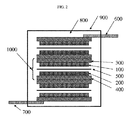
図1は、本発明におけるウルトラキャパシタの一例を示す。遷移金属窒化物粒子を含有し得るアノード電極100は、アノード金属箔300上に形成され、このアノード金属箔300は、アノード電気端子600に接続している。他の側上では、カソード電極200(これは代わりにまたはこれもまた遷移金属窒化物粒子を含有し得る)が、カソード金属箔400上に形成され、このカソード金属箔400は、カソード電気端子700と接続している。セパレーター500を、アノード電極100とカソード電極200との間に置く。これらの構成要素を、電解質800と共にハウジング900中に置く。ウルトラキャパシタが外部電気回路に接続し得るように、アノード電気端子600およびカソード電気端子700はハウジングの外側に延びている。
FIG. 1 shows an example of an ultracapacitor according to the present invention. An
本発明におけるウルトラキャパシタの別の例を、図2に示す。単位コンデンサは、アノード電極100(これは、アノード金属箔300上に形成された遷移金属粒子を含有し得る)、セパレーター500、およびカソード電極200(これはさらに、または代わりに、カソード金属箔400上に形成された遷移金属粒子を含有し得る)からなる。単位コンデンサを、ハウジング900内のコンデンサの直列接続中に置く。最外側の電極は、アノード電気端子600およびカソード電気端子700に接続しており、これらは、より大きな出力電圧を生じさせるためにこれらに接続された電極を有する。構成要素を、電解質800と共にハウジング900中に置く。ウルトラキャパシタが外部電気回路に接続することができるように、アノード電気端子600およびカソード電気端子700はハウジングの外側に延びている。
Another example of the ultracapacitor in the present invention is shown in FIG. The unit capacitor includes an anode electrode 100 (which may contain transition metal particles formed on the anode metal foil 300), a
本発明における遷移金属窒化物または遷移金属窒化物の混合物の粒子は好ましくは、塩基性アモノサーマルプロセスによって合成され、これは、アルカリ鉱化剤を有する超臨界アンモニアを利用する。132.4℃および11.28MPaの臨界点を超えて、アンモニアは超臨界状態となり、これは液体と気体の間の状態である。本発明者らは、強力な還元性鉱化剤(例えば、アルカリ金属)を有する超臨界アンモニアが、遷移金属窒化物を形成することができることを見出した。この工程は、閉鎖した反応器における1ステップ工程であり、一定流量のアンモニアを必要としない。工程温度、圧力、鉱化剤および時間を変化させることによって、粒径は、ナノスケールからミクロンスケールに制御されることが期待される。塩基性アモノサーマル合成の利点は、そのハロゲン化物を含有しない環境である。ハロゲン化物不純物(例えば、塩素)が、内部の構成要素(例えば、金属箔および金属ハウジング)を腐食するため、ハロゲン化物不純物を含有する遷移金属窒化物は、ウルトラキャパシタの信頼性のために好ましくない。さらに、塩基性アモノサーマルプロセスは、合成された遷移金属窒化物にアルカリ金属を意図的にドープすることができ、これは電解質の効率性を助け得る。 The particles of the transition metal nitride or transition metal nitride mixture in the present invention are preferably synthesized by a basic ammonothermal process, which utilizes supercritical ammonia with an alkali mineralizer. Beyond the critical point of 132.4 ° C. and 11.28 MPa, ammonia becomes supercritical, which is a state between liquid and gas. The inventors have found that supercritical ammonia with a strong reducing mineralizer (eg, alkali metal) can form transition metal nitrides. This process is a one-step process in a closed reactor and does not require a constant flow of ammonia. By changing the process temperature, pressure, mineralizer and time, the particle size is expected to be controlled from nanoscale to micron scale. The advantage of basic ammonothermal synthesis is its halide free environment. Transition metal nitrides containing halide impurities are not preferred for ultracapacitor reliability because halide impurities (eg, chlorine) corrode internal components (eg, metal foil and metal housing) . Further, the basic ammonothermal process can intentionally dope the synthesized transition metal nitride with an alkali metal, which can help the efficiency of the electrolyte.
(実施例1)
塩基性アモノサーマルプロセスによって合成された窒化バナジウム粒子を、アノード電極およびカソード電極の両方のために使用する。粒径は100nm未満であり、これは10m2/gより大きい比表面積を提供する。窒化バナジウム粒子を、通常の伝導性粉末材料(例えば、黒鉛粉末)および結合剤と混合し、溶媒に分散させ、そして電気端子ワイヤと共にアルミ箔上でコーティングする。任意のコーティング方法、例えば、ディップコーティング、スプレーコーティング、および印刷を使用することができる。電極/アルミ箔をベーキングした後、窒化バナジウム粒子を含有するコーティングされた膜は、当初の粉末に近い比表面積を有する多孔性膜を形成する。2つの電極は、これらの間のコンデンサグレードの多孔性紙のセパレーターと係合される。絶縁シートを、アノード箔の裏面に付着させる。絶縁シートを使用する代わりに、アルミ箔の裏面上に絶縁酸化膜を形成することができる。次いで、全アセンブリーを、希KOH中に浸漬し、ローリングし、アルミニウムでできた円柱状ハウジング中に置く。電極端子リードワイヤを、適当なゴムまたはプラスチックのブッシングを使用してハウジングから取り出し、ハウジングを注意深く蓋で密封する。必要に応じて、孔を空けたゴムまたはプラスチックのキャップを使用した通気機構を使用し得る。
Example 1
Vanadium nitride particles synthesized by a basic ammonothermal process are used for both the anode and cathode electrodes. The particle size is less than 100 nm, which provides a specific surface area greater than 10 m 2 / g. Vanadium nitride particles are mixed with a conventional conductive powder material (eg, graphite powder) and a binder, dispersed in a solvent, and coated on an aluminum foil with electrical terminal wires. Any coating method can be used, such as dip coating, spray coating, and printing. After baking the electrode / aluminum foil, the coated membrane containing vanadium nitride particles forms a porous membrane with a specific surface area close to the original powder. The two electrodes are engaged with a capacitor grade porous paper separator between them. An insulating sheet is attached to the back side of the anode foil. Instead of using an insulating sheet, an insulating oxide film can be formed on the back surface of the aluminum foil. The entire assembly is then immersed in dilute KOH, rolled and placed in a cylindrical housing made of aluminum. The electrode terminal lead wire is removed from the housing using a suitable rubber or plastic bushing and the housing is carefully sealed with a lid. If desired, a venting mechanism using a perforated rubber or plastic cap may be used.
(実施例2)
実施例1において全アセンブリーをローリングする代わりに、複数のセットのコンデンサアセンブリーを、電気的にこれらを接続することによって積み重ね、希薄KOH中に浸漬し、ボックスハウジング中に置く。適当なゴムまたはプラスチックのブッシングを使用して最外側の電気端子ワイヤをハウジングの外側に取り出した後、蓋を注意深く締め付ける。必要に応じて、孔を空けたゴムキャップを使用した通気機構を使用し得る。
(Example 2)
Instead of rolling the entire assembly in Example 1, multiple sets of capacitor assemblies are stacked by electrically connecting them, immersed in dilute KOH, and placed in a box housing. Carefully tighten the lid after taking the outermost electrical terminal wire out of the housing using a suitable rubber or plastic bushing. If necessary, a venting mechanism using a perforated rubber cap can be used.
(実施例3)
窒化バナジウムを使用する代わりに、窒化バナジウム−窒化ニオブ(vanadium−niobium nitride)粒子を使用して、電極材料の安定性を増強する。
(Example 3)
Instead of using vanadium nitride, vanadium nitride-niobium nitride particles are used to enhance the stability of the electrode material.
本発明における遷移金属窒化物の合成の方法は、超臨界アンモニアを利用し得る。132.4℃および11.28MPaの臨界点を超えて、アンモニアは超臨界状態となり、これは液体と気体との間の状態である。任意選択で、しかし望ましくは、強力な還元性鉱化剤、例えば、アルカリ金属、アルカリ土類金属またはアルミニウムを有する超臨界アンモニアは、遷移金属窒化物を形成することができることを本発明者らは見出した。 The method for synthesizing a transition metal nitride in the present invention can utilize supercritical ammonia. Beyond the critical point of 132.4 ° C. and 11.28 MPa, ammonia becomes a supercritical state, which is a state between liquid and gas. Optionally, but desirably, the inventors have found that supercritical ammonia with strong reducing mineralizers such as alkali metals, alkaline earth metals or aluminum can form transition metal nitrides. I found it.
遷移金属を含有する原料物質は、特定の目的を達成するのに有効な量の遷移金属を含有する。例えば、基材は、窒化物に変換し得る遷移金属の層でコーティングされてもよく、その結果、表面層は、熱バリアまたは摩耗保護表面として有効であり得る。別の例は、粒子が、窒化物への変換によって触媒活性であるか、またはウルトラキャパシタ内に形成されたときに特定の量の電荷を担持する、ある量の遷移金属を含有し得る。原料物質は、10重量パーセント超の遷移金属を含有し得る。 A source material containing a transition metal contains an amount of the transition metal effective to achieve a particular purpose. For example, the substrate may be coated with a layer of transition metal that can be converted to nitride, so that the surface layer can be effective as a thermal barrier or wear protection surface. Another example may be that the particles are catalytically active by conversion to nitride or contain an amount of transition metal that carries a certain amount of charge when formed in an ultracapacitor. The source material may contain more than 10 weight percent transition metal.
この工程は、ある場合においては、閉鎖した反応器における1ステップ工程でよく、一定流量のアンモニアを必要としない。工程温度、圧力、鉱化剤および時間を変化させることによって、層厚さまたは粒径を、ナノスケールからミクロンスケールに制御することが期待される。したがって、このようなバッチ工程によって、反応材料の全てを高圧反応器中に置き、反応が完了した後、生成物を反応器から分離することを可能とし得る。 This process may in some cases be a one-step process in a closed reactor and does not require a constant flow of ammonia. It is expected to control the layer thickness or particle size from nanoscale to micron scale by changing process temperature, pressure, mineralizer and time. Thus, such a batch process may allow all of the reaction materials to be placed in a high pressure reactor and allow the product to be separated from the reactor after the reaction is complete.
上記工程は、別の場合において、アンモニアの一定流量によって、または高圧反応器へのアンモニアの周期的添加によって行ってもよい。したがって、このようなセミバッチ工程によって、反応材料、例えば、原料物質および任意選択の鉱化剤のいくらかを、反応器に最初に加え、アンモニアを連続的または周期的に反応の間に加えることを可能とし得る。さらに、供給源または鉱化剤は、代わりにまたはさらに、連続的または周期的に、反応の間に反応器に加え得る。 In other cases, the above process may be performed by a constant flow rate of ammonia or by periodic addition of ammonia to the high pressure reactor. Thus, such a semi-batch process allows some of the reaction materials, eg, raw materials and optional mineralizers, to be added first to the reactor and ammonia to be added continuously or periodically during the reaction. It can be. In addition, a source or mineralizer may alternatively or additionally be added to the reactor during the reaction, either continuously or periodically.
図4において図示するような標準的工程を、図3に示す。記載したような標準的工程は、高圧反応器3100を使用する。遷移金属3600を含有する原料物質を、鉱化剤と一緒に高圧反応器3100中に置く。鉱化剤は酸素と高度に反応性であるため、窒素またはアルゴンで充填されたグローブボックスにおいて作動させることが好都合である。蓋3200は、ガス吸入ポート3201を有し、これは高圧バルブ3202に接続している。原料物質3600および鉱化剤を高圧反応器3100中にチャージした後、ガスケット3300を使用して蓋3200を閉鎖し、高圧でのアンモニアの漏れを防止する。高圧バルブ3202をまた閉鎖する。次いで、高圧反応器3100をグローブボックスから取り出し、高圧バルブ3202をガス/真空ラインに接続する。高圧バルブ3202を開放することによって、高圧反応器3100を、ガス吸入ポート3201を通してポンピングする。十分な真空レベルを達成した後、高圧反応器3100を液体窒素で外部から冷却し、ガス吸入ポート3201を通してガス状アンモニアで充填する。高圧反応器3100において、ガス状アンモニアを液相に濃縮させる。代わりに、十分な圧力を加えることによって、液体アンモニアを高圧反応器3100に直接導入し得る。所定の量の液体アンモニアを満たした後、高圧バルブ3202を閉鎖し、ガス/真空ラインから切り離す。高圧反応器3100を炉に移し、外部から加熱する。高圧反応器3100は密封してあるため、加熱したアンモニアにより自己加圧され、アンモニアは超臨界状態に達する。鉱化剤をアンモニアに溶解し、アンモノ塩基性溶液3500を生じさせる。高圧反応器3100内の遷移金属3600を含有する原料物質を、アンモノ塩基性溶液3500で窒化する。所定の時間の後、高圧バルブ3202を開放することによってアンモニアを放出する。高圧反応器3100を冷却した後で、遷移金属窒化物を高圧反応器3100から取り出す。遷移金属窒化物を水ですすぎ、鉱化剤を除去する。最後のステップによって、遷移金属窒化物の上面上に酸化薄層が生じる。
The standard process as illustrated in FIG. 4 is shown in FIG. The standard process as described uses a
合成される金属窒化物に基づいて、鉱化剤を選択することができる。ナトリウム金属を一般に使用するが、より高い反応性が必要とされる場合、カリウムベースの鉱化剤を選択してもよい。逆に、より穏やかな反応性が好ましい場合、リチウムベースの鉱化剤を選択してもよい。さらにより穏やかな反応性が好ましい場合、マグネシウムまたはカルシウムベースの鉱化剤を選択し得る。また、酸素の除去が鉱化剤の第一の目的である場合、金属カルシウム、アルミニウムまたはマグネシウムが、鉱化剤に適切であり得る。これらの材料の混合物をまた使用して、反応を制御し得る。 A mineralizer can be selected based on the metal nitride to be synthesized. Sodium metal is commonly used, but if higher reactivity is required, a potassium-based mineralizer may be selected. Conversely, if milder reactivity is preferred, a lithium-based mineralizer may be selected. If even milder reactivity is preferred, a magnesium or calcium based mineralizer may be selected. Also, where calcium removal is the primary purpose of the mineralizer, metallic calcium, aluminum or magnesium may be suitable for the mineralizer. Mixtures of these materials can also be used to control the reaction.
(実施例4)
概ね直径13mmのバナジウム箔および2.6gのNaを、グローブボックスにおいて127ccの内部体積を有する高圧反応器中に置いたが、その中で酸素および水分濃度を0.1ppm未満にレギュレートする。次いで、高圧反応器を密封し、反応器中の窒素を、ガス吸入ポートを通してターボ分子ポンプによって排除した。反応器を10−6ミリバール未満にポンピングした後、液体窒素中に反応器を浸すことによって反応器を冷却し、ガス吸入ポートを通してガス状無水アンモニアを反応器中に導入した。概ね43.7gの液体無水アンモニアを反応器中で濃縮した。次いで、密封した反応器を炉に移し、530〜535℃で5日間加熱した。このように得られた圧力は、167MPa(24,170psi)であった。工程の後、バナジウム箔は、金色がかった色を示したが、これはバナジウム箔の表面が窒化されたことを示す。V2O5の黄色がかった粉末を出発材料として使用したとき、黒色の粉末(VNであると予測される)が得られた。
Example 4
An approximately 13 mm diameter vanadium foil and 2.6 g Na were placed in a high pressure reactor having an internal volume of 127 cc in a glove box, in which the oxygen and moisture concentrations are regulated to less than 0.1 ppm. The high pressure reactor was then sealed and the nitrogen in the reactor was removed by a turbomolecular pump through the gas inlet port. After pumping the reactor to below 10 −6 mbar, the reactor was cooled by immersing the reactor in liquid nitrogen and gaseous anhydrous ammonia was introduced into the reactor through a gas inlet port. Approximately 43.7 g of liquid anhydrous ammonia was concentrated in the reactor. The sealed reactor was then transferred to a furnace and heated at 530-535 ° C. for 5 days. The pressure thus obtained was 167 MPa (24,170 psi). After the process, the vanadium foil showed a goldish color, indicating that the surface of the vanadium foil was nitrided. When a yellowish powder of V 2 O 5 was used as the starting material, a black powder (expected to be VN) was obtained.
(実施例5)
実施例1と同様の実験を、モリブデンおよびチタンについて行い、これらの金属において色の変化を確認した。
(Example 5)
Experiments similar to those in Example 1 were performed on molybdenum and titanium, and color changes were confirmed in these metals.
(実施例6)
実施例1と同様の実験を、ガス吸入ポートおよび高圧バルブを有する高圧反応器で行う。工程の間に、加圧アンモニアを供給し、工程の間に消費されたアンモニアを補充する。
(Example 6)
An experiment similar to Example 1 is performed in a high pressure reactor having a gas inlet port and a high pressure valve. Pressurized ammonia is supplied during the process to replenish the ammonia consumed during the process.
(実施例7)
同様の高圧反応器を使用して、バナジウムを含有するツールまたはパーツを、金属の表面を窒化することによって遷移金属窒化物でコーティングする。また、これらのツールまたはパーツを、アモノサーマルプロセスの前に金属バナジウムでコーティングし、遷移金属窒化物のより厚い保護層を形成する。
(Example 7)
Using a similar high pressure reactor, a tool or part containing vanadium is coated with a transition metal nitride by nitriding the surface of the metal. These tools or parts are also coated with metal vanadium prior to the ammonothermal process to form a thicker protective layer of transition metal nitride.
(実施例8)
高圧反応器は、逐次的に鉱化剤およびアンモニアと共にその中に置かれた下記の粒子を有する。ニオブ、スズ、インジウム、白金、タンタル、ジルコニウム、銅、鉄、タングステン、クロム、モリブデン、ハフニウム、チタン、バナジウム、コバルト、マンガン、セリウム、水銀、プルトニウム、金、銀、イリジウム、パラジウム、イットリウム、ルテニウム、ランタン、セリウム、プラセオジム、ネオジム、プロメチウム、サマリウム、ユウロピウム、ガドリニウム、テルビウム、ジスプロシウム、ホルミウム、エルビウム、ツリウム、イッテルビウム、ルテチウムおよびニッケル。反応器を加熱し、アンモニアを、高圧反応器内で超臨界状態に置く。それぞれの窒化ニオブ、窒化スズ、窒化インジウム、窒化白金、窒化タンタル、窒化ジルコニウム、窒化銅、窒化鉄、窒化タングステン、窒化クロム、窒化モリブデン、窒化ハフニウム、窒化チタン、窒化バナジウム、窒化コバルト、窒化マンガン、窒化セリウム、窒化水銀、窒化プルトニウム、窒化金、窒化銀、窒化イリジウム、窒化パラジウム、窒化イットリウム、窒化ルテニウム、窒化ランタン、窒化セリウム、窒化プラセオジム、窒化ネオジム、窒化プロメチウム、窒化サマリウム、窒化ユウロピウム、窒化ガドリニウム、窒化テルビウム、窒化ジスプロシウム、窒化ホルミウム、窒化エルビウム、窒化ツリウム、窒化イッテルビウム、窒化ルテチウムおよび窒化ニッケルのナノ粒子を得る。工程温度を調節することによって、遷移金属窒化物の好ましい相を得ることができた。
(Example 8)
The high pressure reactor has the following particles placed in it with mineralizer and ammonia sequentially. Niobium, tin, indium, platinum, tantalum, zirconium, copper, iron, tungsten, chromium, molybdenum, hafnium, titanium, vanadium, cobalt, manganese, cerium, mercury, plutonium, gold, silver, iridium, palladium, yttrium, ruthenium, Lanthanum, cerium, praseodymium, neodymium, promethium, samarium, europium, gadolinium, terbium, dysprosium, holmium, erbium, thulium, ytterbium, lutetium and nickel. The reactor is heated and ammonia is placed in a supercritical state in the high pressure reactor. Niobium nitride, tin nitride, indium nitride, platinum nitride, tantalum nitride, zirconium nitride, copper nitride, iron nitride, tungsten nitride, chromium nitride, molybdenum nitride, hafnium nitride, titanium nitride, vanadium nitride, cobalt nitride, manganese nitride, Cerium nitride, mercury nitride, plutonium nitride, gold nitride, silver nitride, iridium nitride, palladium nitride, yttrium nitride, ruthenium nitride, lanthanum nitride, cerium nitride, praseodymium nitride, neodymium nitride, promethium nitride, samarium nitride, europium nitride, gadolinium nitride Nanoparticles of terbium nitride, dysprosium nitride, holmium nitride, erbium nitride, thulium nitride, ytterbium nitride, lutetium nitride and nickel nitride are obtained. By adjusting the process temperature, a favorable phase of transition metal nitride could be obtained.
利点および改善
本発明は、無視できる量のハロゲン化物不純物を有する遷移金属窒化物を使用したウルトラキャパシタを開示する。遷移金属窒化物は好ましくは、ハロゲン化物を含有しない塩基性アモノサーマルプロセスによって合成され、ここでは遷移金属供給源は、反応器中に給送されるときに遷移金属ハロゲン化物を殆ど含有しないか、または全く含有せず、溶媒は、今日商業的に購入され得るようなハロゲン化物を含有しないアンモニアを含み、任意選択の鉱化剤は、ハロゲン化物を殆ど含有しないか、または全く含有しない。この構成の利点は、下記の通りである。
1)電極材料のために遷移金属窒化物粒子を使用することによって高い比エネルギー密度を達成すること。
2)ハロゲン化物不純物による金属部品の潜在的腐食を回避することによって高い信頼性を達成すること。
Advantages and Improvements The present invention discloses ultracapacitors using transition metal nitrides with negligible amounts of halide impurities. Transition metal nitrides are preferably synthesized by a basic ammonothermal process that does not contain halides, where the transition metal source contains little or no transition metal halides when fed into the reactor. The solvent contains ammonia that does not contain halide, as can be purchased commercially today, and the optional mineralizer contains little or no halide. The advantages of this configuration are as follows.
1) Achieving high specific energy density by using transition metal nitride particles for electrode material.
2) Achieve high reliability by avoiding potential corrosion of metal parts due to halide impurities.
本発明はまた、下記の利点の1つまたは複数を有する遷移金属窒化物を生成する新規な方法を開示する。
1)閉鎖した反応器システムによって高度にコスト競争力がある。
2)超臨界アンモニアの高い反応性によって、複雑な構造の表面上に窒化物層を形成することができる。
3)超臨界アンモニアの高い反応性によって、窒化物粒子を形成することができる。
4)好ましくない不純物、例えば、ハロゲンが存在しない。
The present invention also discloses a novel method for producing transition metal nitrides having one or more of the following advantages.
1) Highly cost competitive due to closed reactor system.
2) Due to the high reactivity of supercritical ammonia, a nitride layer can be formed on the surface of a complex structure.
3) Due to the high reactivity of supercritical ammonia, nitride particles can be formed.
4) There are no undesirable impurities such as halogens.
参照文献
本願において考察した全ての参照文献は、参照により本明細書中に援用される。
[1]米国特許出願第2008−0180881A1号。
[2]米国特許出願第2011−0149473A1号。
[3]Patrice SimonおよびYury Gogots、Nature Materials、第7巻(2008年)、845頁。
[4]D.Choi、G.E.BlomgrenおよびP.N.Kumta、Advanced Materials、18巻(2006年)1178頁。
[5]米国特許出願第US2010−0019207A1号。
References All references discussed in this application are hereby incorporated by reference.
[1] US Patent Application No. 2008-0180881A1.
[2] US Patent Application No. 2011-0149473 A1.
[3] Patrice Simon and Yury Gogots, Nature Materials, 7 (2008), 845.
[4] D. Choi, G. E. Blomgren and P.M. N. Kumta, Advanced Materials, 18 (2006), 1178.
[5] US Patent Application No. US2010-0019207A1.
結論
これで、本発明の好ましい実施形態の記載を終了する。下記は、本発明を達成するためのいくつかの代替の実施形態を記載する。
Conclusion This concludes the description of the preferred embodiment of the present invention. The following describes some alternative embodiments for accomplishing the present invention.
実施例は、窒化バナジウムまたは窒化バナジウム−窒化ニオブの粒子を含有する電極を記載したが、他の遷移金属窒化物、例えば、窒化チタン、窒化ジルコニウム、窒化クロム、窒化モリブデン、窒化マンガン、窒化鉄、窒化コバルト、窒化ニッケルを使用することができる。 Examples have described electrodes containing vanadium nitride or vanadium nitride-niobium nitride particles, but other transition metal nitrides such as titanium nitride, zirconium nitride, chromium nitride, molybdenum nitride, manganese nitride, iron nitride, Cobalt nitride and nickel nitride can be used.
実施例は、金属箔のためのアルミ箔を記載したが、他の金属箔、例えば、銅箔および銀箔を使用することができる。 While the examples described aluminum foils for metal foils, other metal foils, such as copper foil and silver foil, can be used.
実施例は、多孔性紙のコンデンサグレードのシートをセパレーターとして記載したが、他のポリマー材料、例えば、セルロースメッシュを使用することができる。 While the examples described a capacitor grade sheet of porous paper as the separator, other polymeric materials, such as cellulose mesh, can be used.
実施例は、希KOHを電解質として記載したが、他の一般に使用される物質、例えば、炭酸プロピレン、アセトニトリル、ホウ酸、ホウ酸ナトリウムまたは他の弱酸(ジプロピルケトン、氷酢酸、乳酸、プロピオン酸、酪酸、クロトン酸、アクリル酸、フェノール、クレゾールなど)を、塩(酢酸アンモニウム、クエン酸アンモニウム、酢酸アルミニウム、乳酸カルシウム、シュウ酸アンモニウム、過ホウ酸ナトリウム、リン酸三ナトリウムなど)、および溶媒(モノエタノールアミン、ジエタノールアミン、トリエタノールアミン、ジエチレングリコール、グリセロールなど)を加えて使用することができる。実施例は、窒化バナジウム、窒化モリブデンおよび窒化チタンを合成する方法を記載するが、他の遷移金属窒化物、例えば、窒化クロム、窒化スカンジウム、窒化ジルコニウムを同じ方法で合成することができる。また、遷移金属窒化物の合金を、同じ方法で合成することができる。 The examples described dilute KOH as the electrolyte, but other commonly used materials such as propylene carbonate, acetonitrile, boric acid, sodium borate or other weak acids (dipropyl ketone, glacial acetic acid, lactic acid, propionic acid , Butyric acid, crotonic acid, acrylic acid, phenol, cresol, etc.), salts (such as ammonium acetate, ammonium citrate, aluminum acetate, calcium lactate, ammonium oxalate, sodium perborate, trisodium phosphate), and solvents ( Monoethanolamine, diethanolamine, triethanolamine, diethylene glycol, glycerol, etc.) can be added and used. While the examples describe a method for synthesizing vanadium nitride, molybdenum nitride and titanium nitride, other transition metal nitrides such as chromium nitride, scandium nitride, zirconium nitride can be synthesized in the same manner. Also, transition metal nitride alloys can be synthesized by the same method.
実施例は、窒化バナジウム、窒化モリブデン、および窒化チタンの箔の合成を記載するが、遷移金属窒化物の他の形態、例えば、ナノ結晶性粒子、微結晶性粒子、薄層、およびバルク単結晶を、同じ方法で生成することができる。また、遷移金属窒化物の低温相、例えば、Fe16N2を好ましくは、合成し得る。 The examples describe the synthesis of vanadium nitride, molybdenum nitride, and titanium nitride foils, but other forms of transition metal nitrides such as nanocrystalline particles, microcrystalline particles, thin layers, and bulk single crystals Can be generated in the same way. Also, a low temperature phase of a transition metal nitride, such as Fe 16 N 2, can be preferably synthesized.
実施例は、Naを鉱化剤として使用した合成方法を記載するが、他のアルカリ金属、アルカリ土類金属またはアルミニウムを、鉱化剤として使用することができる。また、2種または2種より多い鉱化剤の混合物を使用することができる。 The examples describe synthetic methods using Na as a mineralizer, but other alkali metals, alkaline earth metals or aluminum can be used as a mineralizer. Also, a mixture of two or more mineralizers can be used.
好ましい実施形態は、特定の温度および圧力における合成方法を記載するが、アンモニアが超臨界状態である限り、他の温度および圧力の設定を使用することができる。 Although the preferred embodiment describes a synthesis method at specific temperatures and pressures, other temperature and pressure settings can be used as long as the ammonia is in a supercritical state.
好ましい実施形態は、特定の形状の高圧反応器を使用した合成方法を記載するが、他のタイプの高圧反応器、例えば、2つの蓋を有するもの、外部高圧ポンプを有するもの、供給源、鉱化剤またはアンモニアの一定の給送を可能とする高圧吸入ポートを有するものを使用することができる。 Although the preferred embodiment describes a synthesis method using a high pressure reactor of a particular shape, other types of high pressure reactors, for example, having two lids, having an external high pressure pump, source, mineral An agent having a high-pressure inlet port that allows constant feeding of the agent or ammonia can be used.
Claims (15)
(b)カソード電極;
(c)前記アノード電極と前記カソード電極との間のセパレーター;
(d)前記アノード電極と前記カソード電極との間の電解質
を含む、電気エネルギー蓄積装置であって、
少なくとも1つの電極が、無視できる量のハロゲン化物不純物を有するかもしくはハロゲン化物不純物を有さない、遷移金属窒化物または遷移金属窒化物の混合物の粒子を含有し、
前記遷移金属窒化物または遷移金属窒化物の混合物が、アルカリ金属添加剤をさらに含有する、
電気エネルギー蓄積装置。 (A) an anode electrode;
(B) a cathode electrode;
(C) a separator between the anode electrode and the cathode electrode;
(D) an electrical energy storage device comprising an electrolyte between the anode electrode and the cathode electrode,
At least one electrode contains particles of a transition metal nitride or a mixture of transition metal nitrides with or without a negligible amount of halide impurities;
The transition metal nitride or mixture of transition metal nitrides further comprises an alkali metal additive;
Electric energy storage device.
The electrical energy storage device according to any of claims 1 to 13 , wherein the transition metal nitride contains less than 1 ppm halide impurities.
Applications Claiming Priority (5)
| Application Number | Priority Date | Filing Date | Title |
|---|---|---|---|
| US201161501656P | 2011-06-27 | 2011-06-27 | |
| US61/501,656 | 2011-06-27 | ||
| US201161505758P | 2011-07-08 | 2011-07-08 | |
| US61/505,758 | 2011-07-08 | ||
| PCT/US2012/042679 WO2013003073A1 (en) | 2011-06-27 | 2012-06-15 | Ultracapacitors with electrodes containing transition metal nitride |
Publications (3)
| Publication Number | Publication Date |
|---|---|
| JP2014523646A JP2014523646A (en) | 2014-09-11 |
| JP2014523646A5 JP2014523646A5 (en) | 2015-07-30 |
| JP6095657B2 true JP6095657B2 (en) | 2017-03-15 |
Family
ID=46395731
Family Applications (3)
| Application Number | Title | Priority Date | Filing Date |
|---|---|---|---|
| JP2014518619A Expired - Fee Related JP6089032B2 (en) | 2011-06-27 | 2012-06-15 | Transition metal nitride and method for synthesizing transition metal nitride |
| JP2014518618A Expired - Fee Related JP6095657B2 (en) | 2011-06-27 | 2012-06-15 | Ultracapacitors with electrodes containing transition metal nitrides |
| JP2016081753A Withdrawn JP2016130213A (en) | 2011-06-27 | 2016-04-15 | Transition metal nitride and method for synthesizing the same |
Family Applications Before (1)
| Application Number | Title | Priority Date | Filing Date |
|---|---|---|---|
| JP2014518619A Expired - Fee Related JP6089032B2 (en) | 2011-06-27 | 2012-06-15 | Transition metal nitride and method for synthesizing transition metal nitride |
Family Applications After (1)
| Application Number | Title | Priority Date | Filing Date |
|---|---|---|---|
| JP2016081753A Withdrawn JP2016130213A (en) | 2011-06-27 | 2016-04-15 | Transition metal nitride and method for synthesizing the same |
Country Status (5)
| Country | Link |
|---|---|
| US (2) | US8971018B2 (en) |
| EP (2) | EP2724356B1 (en) |
| JP (3) | JP6089032B2 (en) |
| KR (2) | KR20140053100A (en) |
| WO (2) | WO2013003073A1 (en) |
Families Citing this family (19)
| Publication number | Priority date | Publication date | Assignee | Title |
|---|---|---|---|---|
| JP6089032B2 (en) | 2011-06-27 | 2017-03-01 | シックスポイント マテリアルズ, インコーポレイテッド | Transition metal nitride and method for synthesizing transition metal nitride |
| WO2013063070A1 (en) * | 2011-10-24 | 2013-05-02 | The Regents Of The University Of California | Use of alkaline-earth metals to reduce impurity incorporation into a group-iii nitride crystal |
| KR101554675B1 (en) | 2013-11-28 | 2015-09-22 | 한국화학연구원 | Nitride phosphor and method comprising the same |
| CN105621377B (en) * | 2014-10-28 | 2017-11-24 | 中国石油化工股份有限公司 | The preparation method of nitrided iron based on metal-organic framework materials |
| US9822006B2 (en) * | 2015-04-09 | 2017-11-21 | The Boeing Company | Method to form Fe16N2 |
| DE102016215709A1 (en) * | 2015-08-28 | 2017-03-02 | Tsubakimoto Chain Co. | Chain component and chain |
| KR102294518B1 (en) * | 2016-09-30 | 2021-08-27 | 후지필름 가부시키가이샤 | Metal nitride-containing particles, dispersion composition, curable composition, cured film, and their manufacturing method and color filter, solid-state imaging device, solid-state imaging device, infrared sensor |
| JP2021504116A (en) * | 2017-11-29 | 2021-02-15 | コリア インスティチュート オブ エナジー リサーチ | Method for producing a gas-nitrided or liquid-nitrided core-shell catalyst |
| CN109182887B (en) * | 2018-11-18 | 2020-03-10 | 湖南众鑫新材料科技股份有限公司 | Preparation method of nitrided ferrovanadium alloy |
| CN112919428B (en) * | 2019-12-06 | 2023-09-05 | 中国科学院过程工程研究所 | Vanadium nitride microsphere and preparation method and application thereof |
| CN110817813B (en) * | 2019-12-19 | 2022-11-04 | 湖南众鑫新材料科技股份有限公司 | Preparation method of nanocrystalline vanadium nitride powder |
| JP7326183B2 (en) | 2020-02-13 | 2023-08-15 | 太平洋セメント株式会社 | lanthanum nitride |
| CN112058299B (en) * | 2020-09-10 | 2021-11-16 | 中山大学 | Multi-shell nickel-based nitride nano composite material and preparation method and application thereof |
| EP3975213A1 (en) | 2020-09-28 | 2022-03-30 | Jozef Stefan Institute | Method for manufacturing hybrid binder-free electrodes for electrochemical supercapacitors |
| CN112475302B (en) * | 2020-11-16 | 2023-02-24 | 安徽省瑞峻粉末金属材料有限公司 | Preparation method of superfine nanocrystalline VN alloy powder |
| CN113135553B (en) * | 2021-04-22 | 2022-11-04 | 陕西科技大学 | Tungsten nitride coated vanadium nitride powder and preparation method and application thereof |
| CN114180539B (en) * | 2021-12-24 | 2023-08-15 | 广东省科学院半导体研究所 | Nano porous vanadium nitride material, preparation method thereof and energy storage device |
| CN114974937B (en) * | 2022-06-29 | 2022-11-25 | 哈尔滨理工大学 | Preparation method and application of iron-doped cobaltosic oxide/cobalt nitride heterostructure nanowire electrode material |
| CN115537872B (en) * | 2022-10-11 | 2023-12-15 | 重庆大学 | Double-doped efficient electrolytic water catalyst and preparation method and application thereof |
Family Cites Families (29)
| Publication number | Priority date | Publication date | Assignee | Title |
|---|---|---|---|---|
| JPS54145400A (en) * | 1978-05-08 | 1979-11-13 | Ube Ind Ltd | Production of metal nitride powder |
| US4515763A (en) | 1981-07-15 | 1985-05-07 | Board Of Trustees Of Leland Stanford Jr. Univeristy | High specific surface area carbides and nitrides |
| US4851206A (en) * | 1981-07-15 | 1989-07-25 | The Board Of Trustees Of The Leland Stanford Junior University, Stanford University | Methods and compostions involving high specific surface area carbides and nitrides |
| US5680292A (en) | 1994-12-12 | 1997-10-21 | T/J Technologies, Inc. | High surface area nitride, carbide and boride electrodes and methods of fabrication thereof |
| WO1999023712A1 (en) * | 1997-10-30 | 1999-05-14 | T/J Technologies, Inc. | Transition metal-based ceramic material and articles fabricated therefrom |
| DE69842052D1 (en) | 1997-10-30 | 2011-01-27 | Sumitomo Electric Industries | GAN CRYSTAL SUBSTRATE AND MANUFACTURING METHOD |
| US6168694B1 (en) * | 1999-02-04 | 2001-01-02 | Chemat Technology, Inc. | Methods for and products of processing nanostructure nitride, carbonitride and oxycarbonitride electrode power materials by utilizing sol gel technology for supercapacitor applications |
| US6743947B1 (en) | 1999-05-10 | 2004-06-01 | The United States Of America As Represented By The Secretary Of The Army | Electrochemically stable onium salts and electrolytes containing such for electrochemical capacitors |
| KR100904501B1 (en) | 2001-10-26 | 2009-06-25 | 암모노 에스피. 제트오. 오. | Substrate for epitaxy |
| US6924403B2 (en) * | 2002-06-26 | 2005-08-02 | E. I. Du Pont De Nemours And Company | Synthesis of hexafluoropropylene |
| CN100339512C (en) | 2002-06-26 | 2007-09-26 | 波兰商艾蒙诺公司 | Improvemrnt of process for obtaining of bulk monocrystallline gallium-containing nitride |
| TWI334890B (en) | 2002-12-11 | 2010-12-21 | Ammono Sp Zoo | Process for obtaining bulk mono-crystalline gallium-containing nitride, eliminating impurities from the obtained crystal and manufacturing substrates made of bulk mono-crystalline gallium-containing nitride |
| KR101284932B1 (en) * | 2002-12-27 | 2013-07-10 | 제너럴 일렉트릭 캄파니 | Gallium nitride crystal, homoepitaxial gallium nitride-based devices and method for producing same |
| JP4433696B2 (en) * | 2003-06-17 | 2010-03-17 | 三菱化学株式会社 | Method for producing nitride crystal |
| JP2005183556A (en) * | 2003-12-18 | 2005-07-07 | Sii Micro Parts Ltd | Plate-type electrochemical cell |
| PL371405A1 (en) | 2004-11-26 | 2006-05-29 | Ammono Sp.Z O.O. | Method for manufacture of volumetric monocrystals by their growth on crystal nucleus |
| WO2007008198A1 (en) | 2005-07-08 | 2007-01-18 | The Regents Of The University Of California | Method for growing group iii-nitride crystals in supercritical ammonia using an autoclave |
| EP1977029B1 (en) | 2005-12-20 | 2020-07-22 | SLT Technologies, Inc. | Crystalline composition |
| US20070234946A1 (en) * | 2006-04-07 | 2007-10-11 | Tadao Hashimoto | Method for growing large surface area gallium nitride crystals in supercritical ammonia and lagre surface area gallium nitride crystals |
| EP2041794A4 (en) | 2006-06-21 | 2010-07-21 | Univ California | Opto-electronic and electronic devices using n-face or m-plane gan substrate prepared with ammonothermal growth |
| JP5196118B2 (en) * | 2006-09-14 | 2013-05-15 | 信越化学工業株式会社 | Non-aqueous electrolyte secondary battery and manufacturing method thereof |
| EP2100317B1 (en) | 2006-11-15 | 2016-01-27 | Energ2, Inc. | Electric double layer capacitance device |
| WO2009155043A1 (en) | 2008-05-28 | 2009-12-23 | University Of Pittsburgh - Of The Commonwealth System Of Higher Education | Ternary metal transition metal non-oxide nano-particles, methods and applications thereof |
| JP2010040480A (en) * | 2008-08-08 | 2010-02-18 | Oita Univ | Material of electrode, electrode, lithium-ion battery, electric double-layered capacitor, manufacturing method for material of electrode |
| KR101024940B1 (en) * | 2009-02-03 | 2011-03-31 | 삼성전기주식회사 | Hybrid supercapacitor using surface-oxidized transition metal nitride aerogel |
| WO2011084787A1 (en) | 2009-12-21 | 2011-07-14 | Ioxus, Inc. | Improved energy storage in edlcs by utilizing a dielectric layer |
| JP2010100526A (en) * | 2010-01-27 | 2010-05-06 | Lucelabo:Kk | Method for producing transition metal nitride |
| WO2012087409A2 (en) * | 2010-10-12 | 2012-06-28 | The Regents Of The University Of Michigan | High performance transition metal carbide and nitride and boride based asymmetric supercapacitors |
| JP6089032B2 (en) | 2011-06-27 | 2017-03-01 | シックスポイント マテリアルズ, インコーポレイテッド | Transition metal nitride and method for synthesizing transition metal nitride |
-
2012
- 2012-06-15 JP JP2014518619A patent/JP6089032B2/en not_active Expired - Fee Related
- 2012-06-15 WO PCT/US2012/042679 patent/WO2013003073A1/en unknown
- 2012-06-15 JP JP2014518618A patent/JP6095657B2/en not_active Expired - Fee Related
- 2012-06-15 US US13/524,439 patent/US8971018B2/en active Active
- 2012-06-15 EP EP12730334.5A patent/EP2724356B1/en not_active Not-in-force
- 2012-06-15 US US13/524,399 patent/US8920762B2/en active Active
- 2012-06-15 KR KR1020147001024A patent/KR20140053100A/en not_active Application Discontinuation
- 2012-06-15 KR KR1020147001026A patent/KR20140068852A/en not_active Application Discontinuation
- 2012-06-15 WO PCT/US2012/042689 patent/WO2013003074A1/en unknown
- 2012-06-15 EP EP12731245.2A patent/EP2723680A1/en not_active Withdrawn
-
2016
- 2016-04-15 JP JP2016081753A patent/JP2016130213A/en not_active Withdrawn
Also Published As
| Publication number | Publication date |
|---|---|
| US20120327559A1 (en) | 2012-12-27 |
| US8971018B2 (en) | 2015-03-03 |
| JP2016130213A (en) | 2016-07-21 |
| US20120328883A1 (en) | 2012-12-27 |
| KR20140068852A (en) | 2014-06-09 |
| EP2723680A1 (en) | 2014-04-30 |
| EP2724356A1 (en) | 2014-04-30 |
| JP6089032B2 (en) | 2017-03-01 |
| EP2724356B1 (en) | 2018-10-03 |
| JP2014523392A (en) | 2014-09-11 |
| KR20140053100A (en) | 2014-05-07 |
| WO2013003074A1 (en) | 2013-01-03 |
| JP2014523646A (en) | 2014-09-11 |
| WO2013003073A1 (en) | 2013-01-03 |
| US8920762B2 (en) | 2014-12-30 |
Similar Documents
| Publication | Publication Date | Title |
|---|---|---|
| JP6095657B2 (en) | Ultracapacitors with electrodes containing transition metal nitrides | |
| US9114379B2 (en) | Niobium nitride and method for producing same, niobium nitride-containing film and method for producing same, semiconductor, semiconductor device, photocatalyst, hydrogen generation device, and energy system | |
| Naveen et al. | Investigation on physiochemical properties of Mn substituted spinel cobalt oxide for supercapacitor applications | |
| US8734999B2 (en) | Carbon nanotube forming substrate, carbon nanotube complex, energy device, method for manufacturing energy device, and apparatus including energy device | |
| EP3371104B1 (en) | Direct synthesis of carbon doped tio2-bronze nanostructures as anode materials for high performance lithium batteries | |
| US5875092A (en) | Proton inserted ruthenium oxide electrode material for electrochemical capacitors | |
| US9353449B2 (en) | Method for producing NbON film | |
| EP0972294A1 (en) | Electrode materials from hydrous metal and/or hydrous mixed metal oxides and method of preparing the same | |
| Rebekah et al. | Enhanced bifunctional aspects of oxygen vacancy rich cation substituted MnCo2O4 intercalated with g-C3N4 as an oxygen evolution and supercapacitor electrode | |
| RU2671942C1 (en) | Anode material and accumulator | |
| Wang et al. | Hafnium Diboride Spherical Superstructure Born of 5d‐Metal Hf‐MOF‐Induced p Orbital Activity of B Atom and Enhanced Kinetics of Sulfur Cathode Reaction | |
| US11742153B2 (en) | Electrode-forming material for electrochemical capacitors | |
| Kang et al. | Optimized Lithium Deposition on Ag Nanoparticles-Embedded TiO2 Microspheres: A Facile Spray Pyrolysis Approach for Enhanced Lithium Metal Anode | |
| KR100804194B1 (en) | Synthesis of cellular structured green rust and thin films for using them | |
| US10892112B2 (en) | Method of making an energy storage article | |
| JP2006093022A (en) | Air secondary battery |
Legal Events
| Date | Code | Title | Description |
|---|---|---|---|
| A521 | Request for written amendment filed |
Free format text: JAPANESE INTERMEDIATE CODE: A523 Effective date: 20150609 |
|
| A621 | Written request for application examination |
Free format text: JAPANESE INTERMEDIATE CODE: A621 Effective date: 20150609 |
|
| A977 | Report on retrieval |
Free format text: JAPANESE INTERMEDIATE CODE: A971007 Effective date: 20160314 |
|
| A131 | Notification of reasons for refusal |
Free format text: JAPANESE INTERMEDIATE CODE: A131 Effective date: 20160324 |
|
| A521 | Request for written amendment filed |
Free format text: JAPANESE INTERMEDIATE CODE: A523 Effective date: 20160624 |
|
| A131 | Notification of reasons for refusal |
Free format text: JAPANESE INTERMEDIATE CODE: A131 Effective date: 20160824 |
|
| TRDD | Decision of grant or rejection written | ||
| A01 | Written decision to grant a patent or to grant a registration (utility model) |
Free format text: JAPANESE INTERMEDIATE CODE: A01 Effective date: 20170201 |
|
| A61 | First payment of annual fees (during grant procedure) |
Free format text: JAPANESE INTERMEDIATE CODE: A61 Effective date: 20170214 |
|
| R150 | Certificate of patent or registration of utility model |
Ref document number: 6095657 Country of ref document: JP Free format text: JAPANESE INTERMEDIATE CODE: R150 |
|
| R250 | Receipt of annual fees |
Free format text: JAPANESE INTERMEDIATE CODE: R250 |
|
| R250 | Receipt of annual fees |
Free format text: JAPANESE INTERMEDIATE CODE: R250 |
|
| R250 | Receipt of annual fees |
Free format text: JAPANESE INTERMEDIATE CODE: R250 |
|
| LAPS | Cancellation because of no payment of annual fees |