JP6083445B2 - Aseptic filling method and apparatus - Google Patents
Aseptic filling method and apparatus Download PDFInfo
- Publication number
- JP6083445B2 JP6083445B2 JP2015031426A JP2015031426A JP6083445B2 JP 6083445 B2 JP6083445 B2 JP 6083445B2 JP 2015031426 A JP2015031426 A JP 2015031426A JP 2015031426 A JP2015031426 A JP 2015031426A JP 6083445 B2 JP6083445 B2 JP 6083445B2
- Authority
- JP
- Japan
- Prior art keywords
- container
- filling
- sterilization chamber
- chamber
- containers
- Prior art date
- Legal status (The legal status is an assumption and is not a legal conclusion. Google has not performed a legal analysis and makes no representation as to the accuracy of the status listed.)
- Active
Links
Images


Description
本発明は、カップ、トレー等の容器に対して飲料等を無菌充填する方法及び装置に関する。 The present invention relates to a method and apparatus for aseptically filling beverages and the like into containers such as cups and trays.
従来、飲料等の無菌袋詰め製品の製造が、例えば特許文献1に記載されるような手順で行われている。 Conventionally, manufacture of aseptic bag-packed products such as beverages has been performed according to the procedure described in Patent Document 1, for example.
まず、袋が合成樹脂等で作られる。この袋の多数のものが集積されて外装体内に詰め込まれ、密封される。そして、外装体の全体にγ線が照射され、袋の内外面を含む外装体内の全体が殺菌処理される。 First, a bag is made of synthetic resin or the like. A large number of these bags are collected, packed into the exterior body, and sealed. Then, the entire exterior body is irradiated with γ rays, and the entire exterior body including the inner and outer surfaces of the bag is sterilized.
その後、外装体が無菌チャンバー内に取り込まれ、外装体が開封され、外装体から袋が取り出される。袋は無菌チャンバー内で搬送されつつ、開口から飲料等の内容物が充填され、密封され、無菌袋詰め製品とされた後、チャンバー外に取り出される。 Thereafter, the exterior body is taken into the aseptic chamber, the exterior body is opened, and the bag is taken out from the exterior body. The bag is conveyed in the aseptic chamber, filled with contents such as beverages from the opening, sealed, and made into a sterile bag-packed product, and then taken out of the chamber.
また、カップに飲料等の内容物を無菌充填する方法として、特許文献2に記載されるものがある。
Moreover, as a method of aseptically filling a cup with contents such as a beverage, there is one described in
これは、カップを搬送用リテーナの穴に挿入して一方向に搬送しつつ、カップに殺菌剤を吹き付けて殺菌し、カップに熱風を吹き付けて殺菌剤を乾燥させ、しかる後に、カップに飲料等を充填し、最後にカップに蓋材を被せ、ヒートシールによってカップの開口を閉じるようにしている。 This is because the cup is inserted into the hole of the transport retainer and transported in one direction, while the cup is sterilized by spraying a sterilizing agent, hot air is sprayed on the cup to dry the sterilizing agent, and then the cup is filled with beverages, etc. Finally, the cup is covered with a lid and the opening of the cup is closed by heat sealing.
従来の無菌袋詰め方法は、袋をγ線で殺菌することから、袋から異臭が発生しやすいという問題がある。γ線以外に酸化エチレンガス(EOG)を用いて袋を殺菌することも考えられるが、その場合は酸化エチレンガス成分が袋内に残留しやすく、また、殺菌処理に長時間を要するという問題がある。また、従来の無菌袋詰め方法では、オペレーターがチャンバー内で手袋を介した手作業によって外装体を開封し、袋を一枚ずつ外装体から取り出して無菌チャンバー内の搬送装置にセットしなければならないので、無菌袋詰め製品の製造効率が悪いという問題がある。 Since the conventional aseptic bagging method sterilizes the bag with γ rays, there is a problem that a bad odor is likely to be generated from the bag. It is conceivable to sterilize the bag using ethylene oxide gas (EOG) in addition to γ rays, but in that case, the ethylene oxide gas component tends to remain in the bag, and the sterilization treatment takes a long time. is there. Further, in the conventional aseptic bagging method, the operator must open the exterior body manually by using gloves in the chamber, take out the bags one by one from the exterior body, and set them on the transport device in the sterile chamber. Therefore, there is a problem that the production efficiency of aseptic bag-packed products is poor.
上記諸問題は、袋をカップに代えた場合であっても同様である。 The above problems are the same even when the bag is replaced with a cup.
また、従来のカップ用無菌包装方法にあっては、カップが挿入された際、カップのフランジが搬送用リテーナの穴の縁に接する。そのため、カップのフランジの裏面に殺菌剤や熱風が接触し難くなり、殺菌不良が生じやすいという問題がある。また、殺菌剤を乾燥させるための工程を多く必要とするので、熱風の消費量が多大となり、装置も大型化するという問題がある。 Further, in the conventional aseptic packaging method for cups, when the cup is inserted, the flange of the cup comes into contact with the edge of the hole of the retainer for conveyance. Therefore, there is a problem that a sterilizing agent or hot air is less likely to contact the back surface of the flange of the cup, and sterilization defects are likely to occur. Moreover, since many processes for drying a disinfectant are required, there is a problem that the amount of hot air consumed is great and the apparatus is also upsized.
従って、本発明は上記問題点を解決することを課題とする。 Accordingly, an object of the present invention is to solve the above problems.
上記課題を解決するため、本発明は次のような構成を採用する。 In order to solve the above problems, the present invention employs the following configuration.
なお、本発明の理解を容易にするため参照符号をカッコ書きで付するが、本発明はこれに限定されるものではない。 In order to facilitate understanding of the present invention, reference numerals are given in parentheses, but the present invention is not limited to this.
すなわち、請求項1に係る発明は、相互に密着しないよう入れ子状に重ねられた多数の容器(2)からなる容器群を保持すると共に前記容器に接する細かい多数の突起が前記容器群の重ね合わせ方向に沿って突出するように形成された保持部材を前記容器群と共に殺菌チャンバー(6)内に入れ、殺菌チャンバー(6)内を真空域まで減圧したうえで殺菌チャンバー(6)内に過酸化水素のガスを供給して拡散させ、殺菌チャンバー(6)内に大気を導入して殺菌チャンバー(6)内で上記過酸化水素のガスを液体に凝結させ、殺菌チャンバー(6)内を真空域まで減圧して殺菌チャンバー(6)内の上記過酸化水素の液体をガス化させ、その後、殺菌チャンバー(6)内から過酸化水素を除去し、しかる後に、殺菌チャンバー(6)内からこれに隣接する充填チャンバー(7)内へと容器群を移送し、充填チャンバー(7)内で容器群を個々の容器に分けて走行させつつ、各容器(2)に内容物(a)を充填し密封する無菌充填方法を採用する。 In other words, the invention according to claim 1 holds a container group consisting of a large number of containers (2) stacked in a nested manner so as not to adhere to each other, and a large number of fine protrusions in contact with the containers overlap each other. A holding member formed so as to protrude in the direction is put in the sterilization chamber (6) together with the container group, and the sterilization chamber (6) is deoxidized to a vacuum region and then oxidized in the sterilization chamber (6). Hydrogen gas is supplied and diffused, air is introduced into the sterilization chamber (6), the hydrogen peroxide gas is condensed into a liquid in the sterilization chamber (6), and the inside of the sterilization chamber (6) is vacuumed. The hydrogen peroxide liquid in the sterilization chamber (6) is gasified until the hydrogen peroxide is removed from the sterilization chamber (6), and then from the sterilization chamber (6). The container group is transferred into the filling chamber (7) adjacent to the container, and the container group is divided into individual containers in the filling chamber (7), and the contents (a) are transferred to each container (2). Adopt aseptic filling method that fills and seals.
請求項2に記載されるように、請求項1に記載の無菌充填方法において、あらかじめ容器(2)にスタッキングリブ(4)を設けておくことにより容器群における容器同士の密着を防止することも可能である。
As described in
請求項3に記載されるように、請求項1又は請求項2に記載の無菌充填方法において、多数の容器(2)をそれらの開口が下向きになるように重ねたうえで殺菌チャンバー(6)内に入れることも可能である。
As described in
請求項4に係る発明は、相互に密着しないよう入れ子状に重ねられた多数の容器(2)からなる容器群を保持すると共に、前記容器に接する細かい多数の突起が前記容器群の重ね合わせ方向に沿って突出するように形成された保持部材(5)と、容器群を保持した保持部材(5)を収容し、過酸化水素のガスにより容器群を保持部材(5)ごと殺菌処理する殺菌チャンバー(6)と、殺菌チャンバー(6)側から容器群を保持した保持部材(5)が導入される充填チャンバー(7)と、充填チャンバー(7)内で保持部材(5)側から容器(2)を個別に取り出して搬送する搬送手段と、搬送中の容器(2)に内容物(a)を充填する充填手段と、内容物(a)が充填された搬送中の容器(2)を密封する密封手段とを具備した無菌充填装置を採用する。
The invention according to
請求項5に記載されるように、請求項4に記載の無菌充填装置において、容器群をそれらの容器(2)の開口が下向きになるように保持する保持部材(5)が設けられたものとすることも可能である。
As described in
本発明は、相互に密着しないよう入れ子状に重ねられた多数の容器(2)からなる容器群を殺菌チャンバー(6)内に入れ、殺菌チャンバー(6)内を真空域まで減圧したうえで殺菌チャンバー(6)内に過酸化水素のガスを供給して拡散させ、殺菌チャンバー(6)内に大気を導入して殺菌チャンバー(6)内で上記過酸化水素のガスを液体に凝結させ、殺菌チャンバー(6)内を真空域まで減圧して殺菌チャンバー(6)内の上記過酸化水素の液体をガス化させ、その後、殺菌チャンバー(6)内から過酸化水素を除去し、しかる後に、殺菌チャンバー(6)内からこれに隣接する充填チャンバー(7)内へと容器群を移送し、充填チャンバー(7)内で容器群を個々の容器(2)に分けて走行させつつ、各容器(2)に内容物(a)を充填し密封する無菌充填方法であって、容器(2)をγ線で殺菌しないので、容器(2)から異臭が発生するという問題がない。また、容器(2)の殺菌に酸化エチレンガス(EOG)を用いることもないので、容器(2)内における殺菌剤の残留の問題もない。また、容器(2)を搬送用リテーナの穴に入れた状態で殺菌する必要がないので、容器(2)のフランジ(2b)の裏面に殺菌不良が生じるという問題が解消され、さらに、殺菌剤を乾燥させるための工程を多く必要としないので、無菌充填のためのラインが短縮化され、装置構成も小型化される。 In the present invention, a container group consisting of a large number of containers (2) stacked in a nested manner so as not to adhere to each other is placed in a sterilization chamber (6), and the sterilization chamber (6) is depressurized to a vacuum region and then sterilized. Hydrogen peroxide gas is supplied and diffused into the chamber (6), the atmosphere is introduced into the sterilization chamber (6), the hydrogen peroxide gas is condensed into a liquid in the sterilization chamber (6), and sterilized. The inside of the chamber (6) is depressurized to a vacuum region to gasify the hydrogen peroxide liquid in the sterilization chamber (6), and then the hydrogen peroxide is removed from the sterilization chamber (6). The container group is transferred from the inside of the chamber (6) into the filling chamber (7) adjacent thereto, and the container group is moved into individual containers (2) in the filling chamber (7), and each container ( 2) Contents (a) Hama Shi a sterile filling method of sealing, since it does not sterilize the container (2) with γ-rays, there is no problem of odor is generated from the container (2). Moreover, since ethylene oxide gas (EOG) is not used for the sterilization of the container (2), there is no problem of the disinfectant remaining in the container (2). In addition, since it is not necessary to sterilize the container (2) in the state of being placed in the hole of the retainer for conveyance, the problem that the sterilization failure occurs on the back surface of the flange (2b) of the container (2) is solved. Therefore, the line for aseptic filling is shortened, and the apparatus configuration is also downsized.
以下に本発明の実施の形態について説明する。 Embodiments of the present invention will be described below.
最初に、本発明に係る無菌充填方法及び装置により作られるカップ詰め製品である包装体と、包装体を構成する容器について説明する。 First, a package that is a cup-filled product made by the aseptic filling method and apparatus according to the present invention and a container constituting the package will be described.
図1に示すように、包装体1は、容器2と、容器2内に充填された内容物aと、容器2の開口を閉じる蓋3とを具備する。
As shown in FIG. 1, the package 1 includes a
容器2は、例えばカップである。カップは、テーパ壁からなる胴部2aの上端に広口の開口を有し、開口の外周にフランジ2bを有し、底部2cの内周にスタッキングリブ4を有し、全体として合成樹脂で一体成形されている。
The
スタッキングリブ4は、例えば、図2に示すように、複数個の容器2を入れ子状に重ねたときに、容器2,2同士が密着しないようにするための密着防止手段である。このスタッキングリブ4の存在によって、重なり合った容器群から容器2を一個ずつ正確に取り出すことができる。
For example, as shown in FIG. 2, the
スタッキングリブ4は、例えば、図3に示すように、容器2の胴部2aの上端に設けることも可能である。このスタッキングリブ4は、胴部2aの上側部分にストレート壁が形成され、このストレート壁とテーパ壁との間に環状段差壁が与えられることによって形成される。
For example, as shown in FIG. 3, the
容器2がスタッキングリブ4を介して積み重ねられると、容器群内における容器2,2同士の間には隙間が形成されることになる。このため、後に殺菌チャンバー内で供給される過酸化水素のガスが容器群内の各容器2の壁面に接触しやすくなり、それだけ容器2の殺菌効果が高められる。
When the
内容物aは、例えば飲料である。飲料等の内容物aは、あらかじめ殺菌処理され、この殺菌処理後のものが容器2内に充填される。
The content a is, for example, a beverage. Content a such as a beverage is sterilized in advance, and the
蓋3は、図示しないが金属箔にヒートシール層が積層されたシートで構成される。このシートが、内容物aが充填された後の容器2の開口に被せられ、フランジ2bにヒートシール層の面でヒートシールされることにより、容器2が密封される。
Although not shown, the
次に、上記包装体1を製造する無菌充填装置について説明する。 Next, an aseptic filling device for producing the package 1 will be described.
図4に示すように、この無菌充填装置は、入れ子状に重ねられた多数の容器2からなる容器群を保持する保持部材5と、容器群を保持した保持部材5を収容すると、過酸化水素のガスにより容器群を保持部材5ごと殺菌処理する殺菌チャンバー6と、殺菌チャンバー6側から容器群を保持した保持部材5が導入される充填チャンバー7と、充填チャンバー7内で保持部材5側から容器2を個別に取り出して搬送する搬送手段と、搬送中の容器2に内容物aを充填する充填手段と、内容物aが充填された搬送中の容器2を密封する密封手段とを具備する。
As shown in FIG. 4, this aseptic filling apparatus has a holding
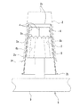
保持部材5は、図5に示すように、多数の容器群を支える支え部8がパレット9上に複数の行列となって設置された構造となっている。
As shown in FIG. 5, the holding
各支え部8は、図5に示すように、容器2であるカップの内壁面に合致しうる円錐台形を呈し、その上端面には容器2内のスタッキングリブ4の上端に接する細かい多数の突起8aが鋸歯状に形成される。これにより、スタッキングリブ4の上端が支え部8に点接触することになり、従って、後に殺菌チャンバー6内で供給される過酸化水素のガスがスタッキングリブ4の上端に接触しやすくなり、スタッキングリブ4の殺菌効果が高められる。
As shown in FIG. 5, each
また、図5に示すように、支え部8には、複数本のトンネル孔8bが形成される。これにより、過酸化水素のガスがこれらの孔8bを通して容器2の内面に到達しやすくなり、容器2の表面の殺菌効果が高められる。
Further, as shown in FIG. 5, a plurality of
上記突起8aは、図6に示すように、先端が面取りされた形状に形成することも可能である。この場合はスタッキングリブ4が突起8a,8a間に嵌まり込み難くなる。
As shown in FIG. 6, the
容器2のスタッキングリブ4が図3に示す形態のものである場合は、支え部8は図7に示すように構成される。すなわち、大小の円錐台が二段重ねされた形状の支え部8がパレット9上に設けられる。容器2が逆様に小円錐台に被せられ、容器2のフランジ2bが大円錐台に乗り上がることで、容器2乃至容器群が支え部8に支えられる。また、大円錐台における容器2のフランジ2bが接する箇所には、多数の突起8aが形成される。後に殺菌チャンバー6内で過酸化水素のガスが供給されると、過酸化水素のガスはフランジ2bと突起8aとの間に形成される隙間から容易に容器2内に流入することとなる。
When the stacking
図4乃至図7に示すように、容器群をそれらの容器2の開口が下側を向いた倒立状態にして保持部材5で保持するようにすると、塵埃等が容器2内に入り難くすることができる。しかし、場合によっては、容器2又は容器群は、図8に示すように、開口を上側にした正立状態で保持部材5により保持することも可能である。その場合の保持部材5における支え部8は、パレット9に凹穴として形成される。容器群の最下部の容器2における底部2c側が凹穴内に挿入されることにより、容器群が保持部材5に支持されることとなる。この場合、多数の突起8aは、凹穴の底に形成される。
As shown in FIG. 4 to FIG. 7, when the container group is held by the holding
殺菌チャンバー6は、図4に示すように、充填チャンバー7の上手側端に接続される。
As shown in FIG. 4, the
殺菌チャンバー6の相対向する一対の壁には開閉可能なシャッター10a,10bが設けられ、そのうち片方のシャッター10bは充填チャンバー7との境に設けられる。
上記容器群を保持した保持部材5は、一方のシャッター10aが開けられることにより殺菌チャンバー6内へと搬入コンベア11によって搬入され、両シャッター10a,10bが閉じられることにより殺菌チャンバー6内に閉じ込められる。そして、容器群が保持部材5とともに殺菌される。
The holding
殺菌チャンバー6内での容器群等の殺菌は、次のようにして行われる。
Sterilization of the container group or the like in the
(a)まず、殺菌チャンバー6内が図示しない真空ポンプによって真空域まで減圧されたうえで、過酸化水素のガスが殺菌チャンバー6内に導入される。これにより、過酸化水素のガスが殺菌チャンバー6内で拡散する。
(A) First, after the inside of the
(b)殺菌チャンバー6内に大気を導入して、殺菌チャンバー6内で上記過酸化水素のガスを液体に凝結させる。これにより、過酸化水素のガスが保持部材5や容器群の各容器2の全表面へと行き渡ったうえで液化する。
(B) The atmosphere is introduced into the
(c)殺菌チャンバー6内が上記真空ポンプによって真空域まで減圧されることにより、殺菌チャンバー6内から排気される。これにより、保持部材5や容器2の隅々に行き渡って液化した上記過酸化水素が再びガス化する。この再度のガス化過程で容器2の表面が殺菌処理される。
(C) The inside of the
(d)上記(a)〜(c)の工程が必要に応じて複数回繰り返される。複数回繰り返されることにより、殺菌効果が高められる。 (D) The steps (a) to (c) are repeated a plurality of times as necessary. By being repeated a plurality of times, the bactericidal effect is enhanced.
(e)上記(d)の工程が終了した後、必要に応じて殺菌チャンバー6内が換気され、殺菌チャンバー6内から残留過酸化水素が除去される。
(E) After the step (d) is completed, the inside of the
殺菌チャンバー6内での殺菌処理が完了すると、充填チャンバー7側のシャッター10bが開いて、保持部材5が容器群を支持した状態のままで充填チャンバー7内に導入される。この導入作業は、殺菌チャンバー6内に設置された搬出コンベア12によって行われる。
When the sterilization process in the
充填チャンバー7は、その内部に、容器群を保持した保持部材5、容器2の搬送手段、容器2内への内容物aの充填手段、容器2の密封手段等を収納可能な容積を有する。
The filling chamber 7 has a volume capable of accommodating therein the holding
また、充填チャンバー7内には、図示しないが、過酸化水素等の殺菌剤を噴霧する殺菌剤噴霧ノズル、無菌エアを吐出する無菌エア吐出ノズル等が配置される。充填チャンバー7内での無菌充填に先立ち、殺菌剤噴霧ノズルから過酸化水素等が噴霧されることにより、充填チャンバー7内が殺菌処理され、殺菌処理後に無菌エア吐出ノズルから無菌エアが吐出されることにより、充填チャンバー7内が陽圧に保たれ、外部からの微生物等の侵入が阻止される。 In the filling chamber 7, although not shown, a disinfectant spray nozzle for spraying a disinfectant such as hydrogen peroxide, an aseptic air discharge nozzle for discharging aseptic air, and the like are arranged. Prior to aseptic filling in the filling chamber 7, the inside of the filling chamber 7 is sterilized by spraying hydrogen peroxide or the like from the sterilizing agent spray nozzle, and sterilized air is discharged from the sterilized air discharge nozzle after sterilization processing. As a result, the inside of the filling chamber 7 is kept at a positive pressure, and the entry of microorganisms and the like from the outside is prevented.
図4に示すように、充填チャンバー7内における殺菌チャンバー6のシャッター10bに隣接した箇所には、搬送コンベア13が配置される。搬送コンベア13は、上記搬出コンベア12と交差する方向に伸びる。充填チャンバー7内の搬送コンベア13上に搬入された保持部材5から後述するロボット14によってすべての容器2が取り除かれると、搬送コンベア13の作動により、保持部材5が充填チャンバー7の図示しない取出口へと搬送される。保持部材5は取出口から充填チャンバー7外に搬出される。
As shown in FIG. 4, a
充填チャンバー7内において、上記搬送コンベア13には、容器群から容器2を個別に取り出して搬送する搬送手段が配置される。
In the filling chamber 7, the
この搬送手段は、上記搬送コンベア13上の各容器群の最上位の容器2を一個ずつ取り出すか、又は容器群の行又は列から容器2を一行又は一列で取り出すロボット14と、ロボット14が取り出した容器2を受け取って充填チャンバー7の排出口へと搬送する移送コンベア15とを具備する。
The transfer means includes a
移送コンベア15は、一方向に間欠走行又は連続走行する無端ベルトを有し、無端ベルトには、各容器2が嵌まり込む穴(図示せず)が形成される。上記ロボット14により容器群から取り出された容器2は、開口を上側にした正立状態とされたうえで移送コンベア15の各穴に挿入される。
The
図4に示すように、移送コンベア15の走行方向に沿って、各容器2に内容物aを充填する充填手段と、内容物aが充填された容器2を密封する密封手段とが順に設けられる。
As shown in FIG. 4, along the traveling direction of the
充填手段は、移送コンベア15に保持された容器2の開口に向かって突出する充填ノズル16を具備する。充填ノズル16の上流側には、図示しないが内容物aを殺菌する殺菌手段、貯留槽、圧送ポンプ等が配置される。各充填ノズル16から各容器2の開口に向かって内容物aが定量ずつ吐出されるようになっている。
The filling means includes a filling
充填ノズル16よりも下流側には、内容物aが充填された容器2のヘッドスペース内に窒素ガス等の不活性ガスを吹き込むための不活性ガス供給ノズル23が、必要に応じて設けられる。
An inert
密封手段は、蓋3となる連続シート3aを容器2のフランジ2bの上面にヒートシールするためのもので、図4に示すように、連続シート供給部と、ヒートシーラー17と、容器2側にシールされた連続シート3aを蓋3ごとに打ち抜く打抜きポンチ18とを具備する。
The sealing means is for heat-sealing the
連続シート供給部は、図4に示すように、蓋3の原反である連続シート3aを殺菌するための連続シート殺菌チャンバー19を備える。この連続シート殺菌チャンバー19は、充填チャンバー7の外側に配置される。連続シート殺菌チャンバー19内には、過酸化水素水等の殺菌剤の貯留槽20が設けられる。
As shown in FIG. 4, the continuous sheet supply unit includes a continuous
連続シート供給部によって、連続シート3aが繰出しロール21から繰り出され、貯留槽20内の殺菌剤である過酸化水素水に浸漬された後に充填チャンバー7内に導入され、充填ノズル16の下流側において移送コンベア15に搬送される容器2側に接合され、充填チャンバー7外へと引き出されて巻取りロール22に巻き取られる。
The continuous sheet supply unit feeds the
ヒートシーラー17は、容器2のフランジ2bに対応する形状の加熱盤を有し、連続シート3aが移送コンベア15の上側走行路に沿って容器2と同期的に走行し始める箇所に配置される。内容物aが充填された容器2が到来すると、加熱盤が容器2の開口に対して接離し、これにより、連続シート3aが容器2のフランジ2bにヒートシールされる。
The
打抜きポンチ18は、容器2のフランジ2bに接着された連続シート3aを容器2を覆う蓋3ごとに打ち抜く打抜き刃を備えており、上記ヒートシーラー17よりもやや下流側に設置される。連続シート3aが接着された容器2が到来すると、打抜き刃が連続シート3aに対して接離し、これにより、連続シート3aが容器2のフランジ2b上で蓋3として打ち抜かれる。これにより、図1に示した包装体1が完成し、充填チャンバー7外へ送り出される。この送り出しは、図示しないがロボット等により行われる。
The punching
次に、上記無菌充填装置の作用について説明する。 Next, the operation of the aseptic filling apparatus will be described.
(1)図2又は図3に示した未封状態の空の容器2が、多数入れ子状に積み重ねられ、棒状に伸びた容器群とされる。このような容器群が多数用意される。
(1) A large number of unsealed
(2)図5乃至図8に示す保持部材5のうちいずれかが用意され、この保持部材5の各支え部8に容器群が装着される。
(2) One of the holding
(3)殺菌チャンバー6の入り口側のシャッター10aが開けられ、図4に示すように、容器群が保持部材5ごと殺菌チャンバー6内に入れられた後、シャッター10aが閉じられる。これにより、殺菌チャンバー6が密閉される。
(3) The
(4)上記(a)〜(e)の処理が行われることにより、殺菌チャンバー6内の容器群及び保持部材5が殺菌される。
(4) By performing the processes (a) to (e), the container group and the holding
(5)殺菌チャンバー6内での殺菌処理が終了すると、充填チャンバー7側のシャッター10bが開き、搬出コンベア12によって容器群が保持部材5ごと充填チャンバー7内に移送される。その後、シャッター10bが閉じられる。
(5) When the sterilization process in the
充填チャンバー7内は、あらかじめ過酸化水素の噴霧等により殺菌処理され、その後吹き込まれる無菌エアによって陽圧に保たれている。 The inside of the filling chamber 7 is previously sterilized by spraying with hydrogen peroxide or the like, and then maintained at a positive pressure by aseptic air blown.
保持部材5は、充填チャンバー7内で、搬送コンベア13上に載せられる。
The holding
(6)ロボット14の動作により、搬送コンベア13上の保持部材5に保持された各容器群における最上位の容器2から取り出され、移送コンベア15の無端ベルトの各穴に挿入される。容器2は、開口が上側になった正立状態で無端ベルトの穴に挿入される。
(6) By the operation of the
(7)移送コンベア15の駆動により、容器2は充填ノズル16、不活性ガス供給ノズル23、ヒートシーラー17、打抜きポンチ18へと間欠的又は連続的に搬送され、内容物aの充填、不活性ガスの供給、容器2の密封、蓋3の打抜きが順に行われる。これにより、図1に示す包装体1が完成する。
(7) By driving the
(8)無菌の包装体1となった容器2は、ロボット等によって充填チャンバー7外へと搬出される。
(8) The
(9)上記包装体1の生産中、空になった保持部材5が、充填チャンバー7の図示しない取出口から充填チャンバー7外へと排出される。そして、殺菌チャンバー6内で殺菌処理された新たな容器群が保持部材5とともに充填チャンバー7内に導入される。
(9) During production of the package 1, the holding
以後、同様な動作が繰り返されて無菌の包装体1の生産が行われる。 Thereafter, similar operations are repeated to produce the sterile package 1.
以下に、実施例及び比較例について説明する。 Examples and comparative examples will be described below.
1.サンプル
実施例1:図2に示した構造のカップを用いた。
実施例2:図2のスタッキングリブをより低く形成した構造のカップを用いた。
実施例3:図3に示した構造のカップを用いた。
比較例:スタッキングリブの無いカップを用いた。
1. Sample Example 1 A cup having the structure shown in FIG. 2 was used.
Example 2 A cup having a structure in which the stacking ribs of FIG. 2 were formed lower was used.
Example 3 A cup having the structure shown in FIG. 3 was used.
Comparative example: A cup without stacking ribs was used.
2.菌付け条件
(1)指標菌:B.atrophaeus ATCC9372
(2)塗布菌数:2.5×10⁵ケ/spot
(3)塗布箇所:いずれのカップにおいても、胴部内面中位部に周方向に6か所(A,B,C,D,E,F)、底部内面中央部に塗布した。図2の高いスタッキングリブを有するカップ及び低いスタッキングリブを有するカップでは、6個のスタッキングリブ(A,B,C,D,E,F)の各々に塗布した。図3のカップでは、スタッキングリブの周方向の6か所(A,B,C,D,E,F)に塗布した。
2. Bacterial conditions
(1) Indicator bacteria: B.atrophaeus ATCC9372
(2) Number of applied bacteria: 2.5 × 10 5 / spot
(3) Location of application: In any cup, 6 locations (A, B, C, D, E, F) in the circumferential direction were applied to the middle portion of the inner surface of the body portion, and applied to the center portion of the inner surface of the bottom portion. In the cup having the high stacking rib and the cup having the low stacking rib in FIG. 2, each of the six stacking ribs (A, B, C, D, E, F) was applied. In the cup of FIG. 3, it applied to six places (A, B, C, D, E, F) of the circumferential direction of a stacking rib.
3.評価項目
(1)殺菌効果
上記サンプルについて実施の形態で述べた(a)〜(d)の処理を行い、処理後にSCDブイヨン培地を適量分注した。37℃×7日間の培養後菌発生の有無を確認した。殺菌効果を示す結果は表1の通りである。
(2)残留過酸化水素量
上記(a)〜(d)の処理を行ったサンプルに、200mlの純水を充填し、十分に振盪後、純水中に溶出した過酸化水素量を酸素電極法で測定した。
3. Evaluation item
(1) Bactericidal effect The above-mentioned samples were subjected to the treatments (a) to (d) described in the embodiment, and an appropriate amount of SCD broth medium was dispensed after the treatment. The presence or absence of bacteria was confirmed after culturing at 37 ° C for 7 days. The results showing the bactericidal effect are shown in Table 1.
(2) Residual hydrogen peroxide amount 200 ml of pure water was charged into the sample subjected to the above treatments (a) to (d), and after shaking well, the amount of hydrogen peroxide eluted in the pure water was determined as the oxygen electrode. Measured by the method.
4.結果
(1)殺菌効果
容器にスタッキングリブが無い場合は、胴部及び底部では6以上の殺菌効果を認めることができなかった。一方、スタッキングリブを設けた容器では、胴部、底部及びスタッキングリブのすべてにおいて6以上の殺菌効果を認めることができた。
(2)残留過酸化水素量
スタッキングリブを設けた容器の残留過酸化水素量は、スタッキングリブの形状の如何を問わず、0.1ppm未満であった。
4). result
(1) Sterilization effect When the container did not have stacking ribs, a sterilization effect of 6 or more could not be recognized at the trunk and bottom. On the other hand, in the container provided with the stacking rib, a sterilizing effect of 6 or more was recognized in all of the trunk portion, the bottom portion, and the stacking rib.
(2) Amount of residual hydrogen peroxide The amount of residual hydrogen peroxide in the container provided with the stacking ribs was less than 0.1 ppm regardless of the shape of the stacking ribs.

2…容器
4…スタッキングリブ
5…保持部材
6…殺菌チャンバー
7…充填チャンバー
a…内容物
2 ...
Claims (5)
Priority Applications (1)
| Application Number | Priority Date | Filing Date | Title |
|---|---|---|---|
| JP2015031426A JP6083445B2 (en) | 2015-02-20 | 2015-02-20 | Aseptic filling method and apparatus |
Applications Claiming Priority (1)
| Application Number | Priority Date | Filing Date | Title |
|---|---|---|---|
| JP2015031426A JP6083445B2 (en) | 2015-02-20 | 2015-02-20 | Aseptic filling method and apparatus |
Publications (2)
| Publication Number | Publication Date |
|---|---|
| JP2016153315A JP2016153315A (en) | 2016-08-25 |
| JP6083445B2 true JP6083445B2 (en) | 2017-02-22 |
Family
ID=56760951
Family Applications (1)
| Application Number | Title | Priority Date | Filing Date |
|---|---|---|---|
| JP2015031426A Active JP6083445B2 (en) | 2015-02-20 | 2015-02-20 | Aseptic filling method and apparatus |
Country Status (1)
| Country | Link |
|---|---|
| JP (1) | JP6083445B2 (en) |
Families Citing this family (2)
| Publication number | Priority date | Publication date | Assignee | Title |
|---|---|---|---|---|
| JP7343753B2 (en) * | 2019-05-28 | 2023-09-13 | 澁谷工業株式会社 | assembly equipment |
| JPWO2022220120A1 (en) * | 2021-04-13 | 2022-10-20 |
Family Cites Families (11)
| Publication number | Priority date | Publication date | Assignee | Title |
|---|---|---|---|---|
| DE2310661B2 (en) * | 1973-03-03 | 1977-10-13 | Ganzhorn u. Stirn, 7170 Schwäbisch Hall | DEVICE FOR STERILIZING STACKABLE CONTAINERS |
| JPS60198156A (en) * | 1984-03-19 | 1985-10-07 | 凸版印刷株式会社 | Sterilization of plastic product |
| DE3525299A1 (en) * | 1985-07-16 | 1987-01-29 | Jagenberg Ag | METHOD AND DEVICE FOR STERILIZING STACKED PACKAGING CONTAINERS, ESPECIALLY STACKED PLASTIC CUP BEFORE FILLING AND SEALING IT |
| DE3900448A1 (en) * | 1989-01-10 | 1990-07-12 | Jagenberg Ag | METHOD AND DEVICE FOR STERILIZING STACKED PACKING ELEMENTS, IN PARTICULAR BOWLS, LID OD. DGL. |
| JPH0958631A (en) * | 1995-08-14 | 1997-03-04 | Toppan Printing Co Ltd | Method and device for sterilization of packaging material |
| US7569180B2 (en) * | 2004-10-12 | 2009-08-04 | Ethicon, Inc. | Sterilization system and method and orifice inlet control apparatus therefor |
| JP4334670B2 (en) * | 1999-05-20 | 2009-09-30 | 大日本印刷株式会社 | Container sterilization method |
| JP2003172800A (en) * | 2001-12-10 | 2003-06-20 | Toyo Ink Mfg Co Ltd | Disinfecting method and device |
| JP5088027B2 (en) * | 2007-07-13 | 2012-12-05 | 大日本印刷株式会社 | Method and apparatus for sterilizing PET cup-like containers |
| JP5573020B2 (en) * | 2009-06-24 | 2014-08-20 | 大日本印刷株式会社 | Method for sterilizing cup-shaped containers |
| JP5534153B2 (en) * | 2009-10-15 | 2014-06-25 | 大日本印刷株式会社 | Method and apparatus for external sterilization of cup-shaped container |
-
2015
- 2015-02-20 JP JP2015031426A patent/JP6083445B2/en active Active
Also Published As
| Publication number | Publication date |
|---|---|
| JP2016153315A (en) | 2016-08-25 |
Similar Documents
| Publication | Publication Date | Title |
|---|---|---|
| EP3157821B1 (en) | Method of manufacturing spouted pouch aseptically filled with contents | |
| JP2018523615A (en) | System for sterilization of thin body flexible container (pouch) | |
| JP6083445B2 (en) | Aseptic filling method and apparatus | |
| US6629401B1 (en) | Method for the sterile packaging products, notably food or beverages, in pouches and corresponding pouch | |
| JP6119806B2 (en) | Aseptic bagging method and apparatus | |
| US20190248525A1 (en) | A method and apparatus for manufacturing a double bag | |
| EP0394734B1 (en) | A method and an apparatus for sterilizing objects by means of a gaseous sterilization agent | |
| JP2020172297A (en) | Aseptic filling machine and aseptic filling method | |
| JPS6149175B2 (en) | ||
| JP5573020B2 (en) | Method for sterilizing cup-shaped containers | |
| JP2002068146A (en) | Sterilizing method for external face of cup container | |
| JP6187424B2 (en) | Aseptic bagging method and apparatus | |
| JPH09240629A (en) | Method and apparatus for sterilizing paper vessel in germless filling apparatus | |
| JPH0958632A (en) | Sterilization device for packaging material | |
| EP3680192A1 (en) | Method for manufacturing packaged food | |
| JP2017095108A (en) | Method and device for sterilizing spouted bag, and sterilized charging method and device for the spouted bag | |
| EP1440887A1 (en) | Method, apparatus and container for vacuum and/or protective atmosphere packaging | |
| JP5971299B2 (en) | Bag sterilization method and apparatus | |
| JP7447424B2 (en) | Aseptic filling machine and aseptic filling method | |
| JP7307396B2 (en) | Aseptic filling machine and aseptic filling method | |
| FI104245B (en) | Device for sterilizing food packaging lids | |
| JP4281902B2 (en) | Container external sterilizer | |
| JPH0958631A (en) | Method and device for sterilization of packaging material | |
| JP5573004B2 (en) | Method for sterilizing cup-shaped containers | |
| JP5359183B2 (en) | Method and apparatus for sterilizing cup-shaped container |
Legal Events
| Date | Code | Title | Description |
|---|---|---|---|
| A131 | Notification of reasons for refusal |
Free format text: JAPANESE INTERMEDIATE CODE: A131 Effective date: 20161004 |
|
| A521 | Written amendment |
Free format text: JAPANESE INTERMEDIATE CODE: A523 Effective date: 20161201 |
|
| TRDD | Decision of grant or rejection written | ||
| A01 | Written decision to grant a patent or to grant a registration (utility model) |
Free format text: JAPANESE INTERMEDIATE CODE: A01 Effective date: 20161227 |
|
| A61 | First payment of annual fees (during grant procedure) |
Free format text: JAPANESE INTERMEDIATE CODE: A61 Effective date: 20170109 |
|
| R150 | Certificate of patent or registration of utility model |
Ref document number: 6083445 Country of ref document: JP Free format text: JAPANESE INTERMEDIATE CODE: R150 |