JP6073312B2 - Winder - Google Patents
Winder Download PDFInfo
- Publication number
- JP6073312B2 JP6073312B2 JP2014520481A JP2014520481A JP6073312B2 JP 6073312 B2 JP6073312 B2 JP 6073312B2 JP 2014520481 A JP2014520481 A JP 2014520481A JP 2014520481 A JP2014520481 A JP 2014520481A JP 6073312 B2 JP6073312 B2 JP 6073312B2
- Authority
- JP
- Japan
- Prior art keywords
- winding
- spindle
- spindles
- roving
- tube
- Prior art date
- Legal status (The legal status is an assumption and is not a legal conclusion. Google has not performed a legal analysis and makes no representation as to the accuracy of the status listed.)
- Expired - Fee Related
Links
Images
Classifications
-
- B—PERFORMING OPERATIONS; TRANSPORTING
- B65—CONVEYING; PACKING; STORING; HANDLING THIN OR FILAMENTARY MATERIAL
- B65H—HANDLING THIN OR FILAMENTARY MATERIAL, e.g. SHEETS, WEBS, CABLES
- B65H54/00—Winding, coiling, or depositing filamentary material
- B65H54/70—Other constructional features of yarn-winding machines
- B65H54/74—Driving arrangements
-
- B—PERFORMING OPERATIONS; TRANSPORTING
- B65—CONVEYING; PACKING; STORING; HANDLING THIN OR FILAMENTARY MATERIAL
- B65H—HANDLING THIN OR FILAMENTARY MATERIAL, e.g. SHEETS, WEBS, CABLES
- B65H54/00—Winding, coiling, or depositing filamentary material
- B65H54/02—Winding and traversing material on to reels, bobbins, tubes, or like package cores or formers
- B65H54/28—Traversing devices; Package-shaping arrangements
-
- B—PERFORMING OPERATIONS; TRANSPORTING
- B65—CONVEYING; PACKING; STORING; HANDLING THIN OR FILAMENTARY MATERIAL
- B65H—HANDLING THIN OR FILAMENTARY MATERIAL, e.g. SHEETS, WEBS, CABLES
- B65H54/00—Winding, coiling, or depositing filamentary material
- B65H54/02—Winding and traversing material on to reels, bobbins, tubes, or like package cores or formers
- B65H54/40—Arrangements for rotating packages
- B65H54/54—Arrangements for supporting cores or formers at winding stations; Securing cores or formers to driving members
- B65H54/543—Securing cores or holders to supporting or driving members, e.g. collapsible mandrels
-
- B—PERFORMING OPERATIONS; TRANSPORTING
- B65—CONVEYING; PACKING; STORING; HANDLING THIN OR FILAMENTARY MATERIAL
- B65H—HANDLING THIN OR FILAMENTARY MATERIAL, e.g. SHEETS, WEBS, CABLES
- B65H67/00—Replacing or removing cores, receptacles, or completed packages at paying-out, winding, or depositing stations
- B65H67/04—Arrangements for removing completed take-up packages and or replacing by cores, formers, or empty receptacles at winding or depositing stations; Transferring material between adjacent full and empty take-up elements
- B65H67/044—Continuous winding apparatus for winding on two or more winding heads in succession
- B65H67/048—Continuous winding apparatus for winding on two or more winding heads in succession having winding heads arranged on rotary capstan head
-
- D—TEXTILES; PAPER
- D01—NATURAL OR MAN-MADE THREADS OR FIBRES; SPINNING
- D01H—SPINNING OR TWISTING
- D01H1/00—Spinning or twisting machines in which the product is wound-up continuously
- D01H1/14—Details
- D01H1/36—Package-shaping arrangements, e.g. building motions, e.g. control for the traversing stroke of ring rails; Stopping ring rails in a predetermined position
-
- D—TEXTILES; PAPER
- D01—NATURAL OR MAN-MADE THREADS OR FIBRES; SPINNING
- D01H—SPINNING OR TWISTING
- D01H7/00—Spinning or twisting arrangements
- D01H7/92—Spinning or twisting arrangements for imparting transient twist, i.e. false twist
-
- B—PERFORMING OPERATIONS; TRANSPORTING
- B65—CONVEYING; PACKING; STORING; HANDLING THIN OR FILAMENTARY MATERIAL
- B65H—HANDLING THIN OR FILAMENTARY MATERIAL, e.g. SHEETS, WEBS, CABLES
- B65H2701/00—Handled material; Storage means
- B65H2701/30—Handled filamentary material
- B65H2701/31—Textiles threads or artificial strands of filaments
Description
本発明は、タレット式巻取りヘッドを用いて巻管に粗糸を巻き取る装置に関する。 The present invention relates to an apparatus for winding a coarse yarn around a winding tube using a turret type winding head.
前紡機によって、いわゆる粗糸又はスライバが製造され、この粗糸又はスライバは、例えばリング精紡機における繊維糸に紡績するための材料として使用される。リング精紡機のための材料として役立つ粗糸は、通常、練条スライバから製造され、この練条スライバは、前紡機のドローフレームにおいてドラフトされ、次いで軽く撚りを加えられ、これによって粗糸をゆがみなしに(verzugsfrei)ボビンに巻成することができる。加えられた撚りは、繊維のまとまりが巻取り、及び再度の繰出し、並びにボビンの搬送のために十分な確実性を有する程度でよい。また他方において、このいわゆる保護撚り(Schutzdrehung)は、リング精紡機におけるドラフトに関しては、さらなる処理プロセスにおいてドラフト障害が発生しないように、僅かであることが必要である。粗糸は、加えられた保護撚りにも拘わらず、ドラフト可能でなくてはならない。 A so-called roving yarn or sliver is produced by a pre-spinning machine, and this roving yarn or sliver is used as a material for spinning fiber yarns in, for example, a ring spinning machine. The roving yarn, which serves as a material for the ring spinning machine, is usually produced from a drawing sliver, which is drafted in a draw frame of a pre-spinning machine and then lightly twisted, thereby distorting the roving yarn. Can be wound on bobbins without (verzugsfrei). The added twist may be such that the fiber mass has sufficient certainty for winding and re-feeding and bobbin transport. On the other hand, this so-called protective twist needs to be small with respect to the draft in the ring spinning machine so that no draft failure occurs in further processing. The roving must be draftable despite the added protective twist.
粗糸を製造するために、前紡機としていわゆるフライヤ加撚機構が使用される。フライヤ加撚機構は典型的には、ドローフレームと、フライヤを用いてフライヤ巻管に粗糸を巻き取るためのスピンドルとを備えている。プロセス技術上の理由から、フライヤ巻管もしくは、フライヤ巻管を受容するためのスピンドルは、鉛直に方向付けられている。フライヤを用いた保護撚りの付与及び粗糸の巻取りは、1つのプロセスステップにおいて行われ、この場合スピンドルは、該スピンドルに被せられたフライヤ巻管と共に回転し、かつ繊維束もしくはスライバをフライヤ巻管に導くフライヤは、フライヤ巻管の周囲を回転する。完成したボビンは、今日、自動式のドッファを用いて前紡機から取り出され、自動式の移動装置においてフライヤ加撚機構からリング精紡機に、さらなる処理のために供給される。 In order to produce a roving yarn, a so-called flyer twisting mechanism is used as a pre-spinning machine. The flyer twisting mechanism typically includes a draw frame and a spindle for winding the roving yarn around the flyer winding tube using the flyer. For reasons of process technology, the flyer tube or spindle for receiving the flyer tube is oriented vertically. The application of protective twist and the winding of roving yarn using a flyer are carried out in one process step, in which case the spindle rotates with a flyer winding tube placed over the spindle and the fiber bundle or sliver is wound on the flyer. The flyer leading to the tube rotates around the flyer winding tube. The finished bobbin is today removed from the pre-spinning machine using an automatic doffer and fed from a flyer twisting mechanism to a ring spinning machine for further processing in an automated moving device.
しかしながらまた、時間の経過と共に、通常のフライヤ加撚機構とは異なった形態の前精紡機も公知となっており、これらの前精紡機において共通なことは、粗糸に、ドローフレームに後置された加撚機構において保護撚りが加えられることである。保護撚りを備えた粗糸は、次いで巻取り装置に供給される。保護撚りの付与及び粗糸の巻取りは、互いに無関係な2つのプロセスステップにおいて行われる。相応に、このような前紡機では、フライヤ加撚機構におけるものとは異なった巻取り装置を使用することができる。 However, with the passage of time, pre-spinning machines having different forms from the usual flyer twisting mechanism are also known, and what is common in these pre-spinning machines is that they are placed on the roving yarn and on the draw frame. A protective twist is added in the twisting mechanism. The roving with the protective twist is then fed to the winding device. The application of protective twist and the winding of the roving are performed in two process steps which are independent of each other. Correspondingly, such a pre-spinning machine can use a winding device different from that in the flyer twisting mechanism.
このような巻取り装置は、EP2112258に基づいて公知である。開示された巻取り装置の構造において、前紡機の高い供給速度を得ることができる。しかしながらEP2112258に開示された巻取り装置には、次のような欠点がある。すなわちこの公知の巻取り装置では、満管のボビンと空の巻管とを交換するために、巻取りプロセスを、ひいては加撚機構からの粗糸の供給を中断する必要がある。加撚機構の構成に応じて、中断後の紡績開始は、生産性及び品質に関する損失を意味する。 Such a winding device is known from EP211258. In the disclosed winding device structure, a high feeding speed of the pre-spinning machine can be obtained. However, the winding device disclosed in EP211258 has the following drawbacks. That is, in this known winding device, in order to replace the full bobbin and the empty winding tube, it is necessary to interrupt the winding process, and thus the supply of the roving yarn from the twisting mechanism. Depending on the configuration of the twisting mechanism, the start of spinning after interruption means a loss in productivity and quality.
EP2112258に開示された前紡機における今日汎用のフライヤ巻管の使用によって、600m/分及びそれ以上の高い供給出力では、極めて頻繁な巻管交換が必要である。これによってEP2112258に開示された巻取り装置は、フライヤ巻管を使用するのに適していない。従来技術によるフライヤ巻管は、例えばEP0927696によって開示されている。フライヤ巻管は、周壁外面と周壁内面とを備えた巻管である。周壁外面は、繊維材料から成る粗糸を巻成するために働き、スタータベルト又は、ボビン交換後における巻取りの開始時に粗糸端部を受容するための他の装置を備えた領域を有する。周壁内面は、この周壁内面のサイズ及び形状が、従来技術に基づいて公知の、満管又は空管を搬送するための手段によって、又は粗糸をさらに処理するための装置において受容されるのに、適するように構成されている。 Due to the use of today's universal flyer windings in the pre-spinning machine disclosed in EP211258, very frequent tube changes are required at feed rates as high as 600 m / min and higher. As a result, the winding device disclosed in EP211258 is not suitable for using flyer winding tubes. A flyer wound tube according to the prior art is disclosed, for example, by EP0927696. The flyer wound tube is a wound tube having an outer peripheral wall surface and an inner peripheral wall surface. The outer surface of the peripheral wall serves to wind the roving made of fiber material and has a region with a starter belt or other device for receiving the roving end at the start of winding after the bobbin change. The inner surface of the peripheral wall is such that the size and shape of the inner surface of the peripheral wall is received by means for conveying full or empty pipes known in the prior art or in devices for further processing of roving yarn. Configured to be suitable.
化学繊維製造から、連続的に到来する糸のために適した巻取り機が公知である。このような巻取り機は、例えばEP1053967に開示されている。この巻取り機はタレット式巻取りヘッドを有し、このタレット式巻取りヘッドには、2つのスピンドルが保持されている。第1のスピンドルは巻取りポジションに位置し、第2のスピンドルはドッファポジションに位置している。ドッファポジションにおいて満管のボビンはスピンドルから取り出され、空の巻管と交換される。巻取りポジションに位置するボビンが満管になると、タレットは180°回転させられ、両スピンドルはそのポジションを交換する。巻き上げられる糸は、供給の中断なしに、行われる回転によって満管のボビンから切り離され、空の巻管によって引き受けられる。スピンドルは水平に配置されている。さらに糸は、綾振り装置によってゆがみなしに巻き取られる。糸をそこから綾振り装置に変更する糸ガイドは、綾振り装置自体から特定の間隔をおいて離れている。これによって、糸ガイドから綾振り装置の最も外側の位置に導かれる糸に対しては、綾振り装置が中央位置にある場合よりも、長い距離が生じる。この長い距離に基づいて、綾振り装置の各運動と共に、ある程度のゆがみが発生する。 From chemical fiber production, winding machines suitable for continuously incoming yarns are known. Such a winder is disclosed, for example, in EP 1053967. This winding machine has a turret type winding head, and the turret type winding head holds two spindles. The first spindle is located at the winding position, and the second spindle is located at the doffer position. In the doffer position, the full bobbin is removed from the spindle and replaced with an empty winding tube. When the bobbin located at the winding position becomes full, the turret is rotated 180 °, and both spindles exchange their positions. The wound yarn is separated from the full bobbin by the rotation that takes place without interruption of the supply and is taken over by the empty winding tube. The spindle is arranged horizontally. Furthermore, the yarn is wound without distortion by the traverse device. The yarn guide from which the yarn is changed to the traversing device is separated from the traversing device itself by a certain distance. This causes a longer distance for the yarn guided from the yarn guide to the outermost position of the traversing device than when the traversing device is in the central position. Based on this long distance, some distortion occurs with each movement of the traverse device.
ゆえに本発明の課題は、粗糸を中断なしにかつゆがみなしに巻き取ることができ、しかも汎用のフライヤ巻管の使用を妨げない、粗糸を巻き取る装置を提供することである。 Therefore, an object of the present invention is to provide an apparatus for winding up a roving yarn that can wind up the roving yarn without interruption and without distortion, and does not hinder the use of a general-purpose flyer winding tube.
この課題は、独立請求項である請求項1の特徴部記載のように構成された、タレット式巻取りヘッドを用いて粗糸を巻き取る装置によって解決される。タレット式巻取りヘッドは、タレットベースプレートを有し、該タレットベースプレートは、巻管を受容するために設けられかつ該タレットベースプレートに保持された2つのスピンドルを備え、両方のスピンドルはそれぞれ長手方向軸線を有している。タレットベースプレート及び両スピンドルは、それぞれ1つの固有の駆動装置を備えている。両方のスピンドルの長手方向軸線は、鉛直方向に方向付けられている。 This problem is solved by an apparatus for winding a roving yarn using a turret type winding head configured as described in the characterizing portion of claim 1 which is an independent claim. The turret take-up head has a turret base plate, the turret base plate comprising two spindles provided for receiving and held by the turret base plate, both spindles each having a longitudinal axis. Have. The turret base plate and both spindles each have one unique drive. The longitudinal axes of both spindles are oriented in the vertical direction.
粗糸を巻き取る装置は、粗糸の製造とは無関係に考察することができる。それというのは、巻取り装置と粗糸紡績機との間に機械式の結合部が存在する必要がないからである。ただ1つ制御技術的に接続部を形成することだけが必要である。それというのは、巻取り装置の運転は、巻き取られる粗糸の供給に関連しているからである。装置はタレットベースプレートを有し、このタレットベースプレートは、機械フレームに水平な位置で回転可能に支持されている。タレットベースプレートは、駆動装置、好ましくは電動機によって、ボビン交換のために半回転(180°)回転させられる。この回転もしくはボビン交換は、粗糸長さ測定によって又は測定もしくは設定された巻取り時間に基づいて、開始することができる。しかしながらまた、例えばボビン直径のような他の指示形態も使用可能である。タレットベースプレートの回転によって、巻取り部に空の巻管が供給され、巻き上げられる粗糸はこの空の巻管によって引き受けられる。このようにして、巻管交換時に粗糸供給を中断する必要がなくなる。そして中断のない巻取り過程、ひいては中断のない粗糸製造が可能になる。 The device for winding the roving yarn can be considered regardless of the production of the roving yarn. This is because there is no need for a mechanical coupling between the winding device and the roving spinning machine. It is only necessary to form the connection in terms of one control technique. This is because the operation of the winding device is related to the supply of the roving to be wound. The apparatus has a turret base plate that is rotatably supported in a horizontal position on the machine frame. The turret base plate is rotated half a turn (180 °) for bobbin replacement by a drive, preferably an electric motor. This rotation or bobbin exchange can be initiated by measuring the roving length or based on the measured or set winding time. However, other indication forms such as bobbin diameter can also be used. By rotating the turret base plate, an empty winding tube is supplied to the winding unit, and the roving yarn to be wound is accepted by the empty winding tube. In this way, it is not necessary to interrupt the supply of roving yarn when replacing the winding tube. Thus, the winding process without interruption and the production of roving without interruption can be realized.
タレットベースプレートには、巻管を受容するための2つのスピンドルが保持され、かつ回転可能に支持されている。両スピンドルは、タレットベースプレートにおいて突出して保持されていて、支持部とは反対側の自由端部から巻管を装着することができる。スピンドルは、タレットベースプレートにおいて互いに向かい合って位置するように配置されている。両スピンドルはそれぞれ、固有の駆動装置を備えている。駆動装置は好ましくは、スピンドルへの力伝達のために、第1の伝動装置段とチェーン駆動装置又はベルト駆動装置を備えた電動機を有する。チェーン駆動装置又はベルト駆動装置は、タレットベースプレートの回転時に、該タレットベースプレートに保持された両スピンドルはそのポジションを交換するが、それぞれ所属の駆動装置はそのポジションに変わらずに留まることを可能にする。しかしながらまた、駆動装置を直にスピンドルに取り付けること及び必要なエネルギのための相応な回転伝達装置を設けることも可能である。このような回転伝達装置は、従来技術に基づいて公知である。 The turret base plate holds two spindles for receiving the winding tubes and is rotatably supported. Both spindles are held protruding from the turret base plate, and a winding tube can be mounted from a free end opposite to the support portion. The spindles are arranged to face each other on the turret base plate. Each spindle has its own drive. The drive preferably has an electric motor with a first gear stage and a chain drive or belt drive for force transmission to the spindle. The chain drive or belt drive allows the spindles held by the turret base plate to change their positions when the turret base plate rotates, but the respective drive devices can remain unchanged at that position. . However, it is also possible to mount the drive directly on the spindle and to provide a corresponding rotation transmission device for the required energy. Such a rotation transmission device is known based on the prior art.
スピンドルの長手方向軸線は、鉛直方向に方向付けられている。これによって、巻管として、従来技術に基づいて公知のフライヤ巻管を使用することが可能になる。その結果、巻取り装置によって形成されたボビンと、紡績工場において使用されるフライヤ巻管との両立性もしくは互換性が得られる。このようなフライヤ巻管は、粗糸を巻成するために働く円筒形の周壁外面を有する。フライヤ巻管は公知のようにスピンドルに指示される。好ましくはスピンドルの上側3分の1に、固定エレメントが設けられている。巻管は、汎用のフライヤ加撚機構におけるように、スピンドルの下側領域においてタレットベースプレートに保持され、固定エレメントによってスピンドルの上側領域において固定される。これによって、高回転数時にも巻管の十分に安定した回転が可能になる。好ましくは、固定エレメントは空気力式の緊締装置として設けられている。巻管は、タレットベースプレートにおける保持と固定エレメントとによってスピンドルに回動不能に保持されている。 The longitudinal axis of the spindle is oriented in the vertical direction. This makes it possible to use a known flyer winding tube based on the prior art as the winding tube. As a result, compatibility or compatibility between the bobbin formed by the winding device and the flyer winding tube used in the spinning factory can be obtained. Such a flyer-wound tube has a cylindrical peripheral wall outer surface that serves to wind the roving. The flyer tube is directed to the spindle as is well known. A fixing element is preferably provided on the upper third of the spindle. The winding tube is held on the turret base plate in the lower region of the spindle and fixed in the upper region of the spindle by a fixing element, as in a general purpose flyer twisting mechanism. This enables sufficiently stable rotation of the wound tube even at high rotational speeds. Preferably, the fixing element is provided as an aerodynamic clamping device. The winding tube is non-rotatably held on the spindle by the holding on the turret base plate and the fixing element.
粗糸は、綾振り手段を介して、回転運動させられる巻管に供給される。綾振り手段は、主として、機械フレームに堅固に結合された保持体と、巻管の長手方向軸線に沿って可動のエレメントとから成っている。綾振り装置はその構造形式によって、粗糸のゆがみもしくはむらのない巻取りを可能にする。綾振り手段の可動のエレメントとしては、例えばプレスフィンガ又は巻取り供給ローラ対が設けられていてよい。プレスフィンガの構造形式は、フライヤ技術に基づいて一般に公知である。巻取り供給ローラ対の構成も同様に従来技術、例えばEP2112258に基づいて公知である。 The roving is supplied to a winding tube that is rotated through a traversing means. The traversing means mainly consists of a holding body firmly connected to the machine frame and an element movable along the longitudinal axis of the winding tube. The traversing device enables winding of the roving without distortion or unevenness depending on the structure type. As the movable element of the traversing means, for example, a press finger or a winding supply roller pair may be provided. The structure of the press fingers is generally known based on flyer technology. The construction of the winding supply roller pair is likewise known on the basis of the prior art, for example EP211258.
スピンドルの回転数、ひいては巻管の回転数は、粗糸の供給速度によって決定される。粗糸の製造は例えば、空気紡績法によって行うことができる。製造部からの粗糸の供給は、例えばガイド装置を介して直接、巻取り部に行うことができる。粗糸を巻き取るための装置は、同様に、粗糸を引き受けるためのガイドを有する。粗糸が巻き付けられるスピンドルの回転数を制御するために、供給される粗糸の速度によって制御を行うことができる。そのためには、相応なセンサが設ける必要がある。しかしながらより好ましくは、粗糸製造部からの進出部箇所と巻取り部への到達箇所との間において粗糸が自由に弛むように、粗糸がガイド装置を介してもたらされる。製造部と巻取り部との間において速度差が発生した場合には、弛みが変化する。そして弛みセンサを介して、スピンドルの必要な回転数を相応に制御することができる。このようにして、巻取り部の箇所におけるボビン直径の増大に基づく、周速度の変化もまた考慮される。 The rotational speed of the spindle, and hence the rotational speed of the winding tube, is determined by the supply speed of the roving yarn. For example, the roving can be produced by an air spinning method. The supply of the roving yarn from the production unit can be performed directly to the winding unit via a guide device, for example. The device for winding the roving yarn likewise has a guide for taking up the roving yarn. In order to control the number of rotations of the spindle around which the roving yarn is wound, the control can be performed according to the speed of the roving yarn supplied. For this purpose, it is necessary to provide a suitable sensor. More preferably, however, the roving is brought through the guide device so that the roving is loosened freely between the advancement part from the roving production part and the arrival part to the winding part. When a speed difference occurs between the manufacturing unit and the winding unit, the slack changes. The required number of rotations of the spindle can then be controlled accordingly via the slack sensor. In this way, changes in peripheral speed due to an increase in bobbin diameter at the winding site are also taken into account.
さらに本発明は、本発明による装置を使用して巻管に粗糸を巻き取る方法にも関する。本発明による方法は、第1のスピンドルが巻取りポジションに位置し、かつ第2のスピンドルがドッファポジションに位置することによって、特徴付けられている。巻取りポジションにおいて粗糸は、巻管に巻き取られ、そのために、巻取りポジションに位置するスピンドルの駆動装置は作動させられる。ドッファポジションでは、満管のボビンが取り出され、空の巻管がスピンドルに装着される。従って、ドッファポジションに位置するスピンドルの駆動装置は、作動していない。そしてタレットベースプレートの回転によって、第1のスピンドルと第2のスピンドルとのポジションは交換させられる。相応に両方のスピンドルの駆動装置の運転状態も変化させられる。満管の巻管を有する第1のスピンドルは、タレットベースプレートの回転によって綾振り手段から遠ざけられる。同時に、空の巻管を有する第2のスピンドルが、綾振り手段に向かって移動させられる。第2のスピンドルが綾振り手段に達すると、粗糸は空の巻管へともたらされ、満管の巻管からは切り離される。そのために空の巻管には、粗糸の引受けを可能にする掴み装置が設けられている。従来技術に基づいて、フライヤ巻管に制限された領域においてベルクロテープを設けることが、公知である。ベルクロテープは、粗糸がベルクロテープに接触するや否や、粗糸が空の巻管によって引き受けられるようになっている。粗糸が第2のスピンドルにおける空の巻管によって受け止められるや否や、満管の巻管を備えた第1のスピンドルは、その回転を停止させられ、満管の巻管は空の巻管と交換させられる。 The invention further relates to a method for winding a roving around a winding tube using the device according to the invention. The method according to the invention is characterized in that the first spindle is located in the winding position and the second spindle is located in the doffer position. In the winding position, the roving yarn is wound on the winding tube, and for this purpose, the spindle drive located at the winding position is activated. In the doffer position, the full bobbin is removed and an empty winding tube is mounted on the spindle. Therefore, the spindle driving device located at the doffer position is not operating. The positions of the first spindle and the second spindle are exchanged by the rotation of the turret base plate. Correspondingly, the operating states of the drive units of both spindles can be changed. A first spindle having a full tube is moved away from the traversing means by rotation of the turret base plate. At the same time, a second spindle with an empty winding is moved towards the traversing means. When the second spindle reaches the traversing means, the roving is brought into an empty winding tube and separated from the full winding tube. For this purpose, the empty winding tube is provided with a gripping device that enables the acceptance of the roving yarn. Based on the prior art, it is known to provide velcro tape in an area limited to a flyer winding. The Velcro tape is adapted to be received by an empty winding tube as soon as the roving yarn comes into contact with the Velcro tape. As soon as the roving yarn is received by the empty winding tube on the second spindle, the first spindle with the full winding tube is stopped rotating and the full winding tube is connected to the empty winding tube. Be exchanged.
好ましくは、空の巻管はタレットベースプレートの回転によって、綾振り手段から満管の巻管へと延びる粗糸の走路内へと回転させられる。このようなボビンもしくは巻管の交換の確実性を高めるために、粗糸をタレットベースプレートの回転中に引渡し箇所に接近案内する、又は粗糸を空の巻管に大きな角度をもって巻き掛ける案内手段を、使用することも可能である。 Preferably, the empty winding tube is rotated by the rotation of the turret base plate into the course of the roving that extends from the traversing means to the full winding tube. In order to increase the reliability of such bobbin or winding tube replacement, guide means for guiding the coarse yarn close to the delivery point during rotation of the turret base plate or winding the coarse yarn around the empty winding tube at a large angle is provided. It is also possible to use.
タレットベースプレートの回転によってさらに、粗糸は満管のボビンから切り離され、新たな空の巻管によって引き受けられる。このような方法形態によって、中断のない巻取り運転が可能になる。また、製造装置によって確定される、粗糸の供給速度を、交換過程中に調整もしくは適合させることも不要である。その結果、障害のない安定した運転が連続した出力で可能になる。 The rotation of the turret base plate further causes the roving to be disconnected from the full bobbin and taken over by a new empty winding tube. Such a method configuration enables uninterrupted winding operation. In addition, it is not necessary to adjust or adapt the supply speed of the roving yarn determined by the production apparatus during the exchange process. As a result, stable operation without any obstacle is possible with continuous output.
次に図面を参照しながら本発明の実施形態を説明する。 Next, embodiments of the present invention will be described with reference to the drawings.
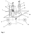
図1には、タレット式巻取りヘッドが概略的に示されている。機械フレーム20には、タレットベースプレート2が保持され、かつ回転可能に支持されている。タレットベースプレート2は水平に配置されていて、鉛直の回転軸線3を有する。タレットベースプレート2は、駆動装置4によって回転軸線3を中心にして180°のステップで回転させられる(矢印5参照)。タレットベースプレート2には、第1のスピンドル6と第2のスピンドル11とが保持され、かつ回転可能に支持されている。第1のスピンドル6は、回転軸線7を介して駆動装置8に接続されている。第2のスピンドル11は、回転軸線12を介して駆動装置13に接続されている。第1及び第2のスピンドル6,11は、互いに無関係に独立して駆動される。第1及び第2のスピンドル6,11の駆動装置8,13は、好ましくは、周波数制御装置を備えて構成されている。
FIG. 1 schematically shows a turret winding head. The
第1のスピンドル6は、図1の図示において巻取りポジションに位置している。このスピンドル6には、空の巻管9が装着されている。この巻管9に粗糸1が巻き取られる。粗糸1は綾振り手段10を介して巻管9に巻き取られる。綾振り手段10は機械フレーム20に結合されていて、かつ機械フレーム20によって保持されている。綾振り手段10は可動のエレメントを有し、この可動のエレメントは、巻管9に沿って上下運動し、これによって、回転軸線7を中心にして回転する巻管9には均一な巻成体が形成される。
The
第2のスピンドル11は、図1の図示においてドッファポジションに位置している。第2のスピンドル11からは既に満管の巻管が取り外されている。満管の巻管の取外し及び空の巻管の装着は、相応なマニプレータ又はロボットによって自動的に行うことができる。スピンドル11はその上側領域に固定エレメント14を備えている。この固定エレメント14は、スピンドル11において巻管9を安定させるために働く。空の巻管9は、上からスピンドル11に装着され、次いで固定エレメント14によって回動不能に保持される。固定エレメント14は例えば空気力式の緊締装置であってよく、この緊締装置は、巻管の装着後に無圧にされ、これにより半径方向に拡張され、その結果、巻管はスピンドル11にしっかりと固定される。
The
巻管9に粗糸1が完全に巻き付けられ、巻管9が満管状態になると、タレットベースプレート2は駆動装置4によってその軸線3を中心にして、半回転(180°)矢印5の方向に回転させられる。これによって第1のスピンドル6と第2のスピンドル11とはポジションを交換する。綾振り手段10は、タレットベースプレート2の回転とは一緒に移動しない。タレットベースプレート2の回転によって、第2のスピンドル11に位置する空の巻管9は、巻取りポジションに、ひいては粗糸1の走路内に回転させられる。これによって粗糸1は、空の巻管によって引き受けられ、満管の巻管から切り離される。空の巻管に粗糸1を引き受けるために、空の巻管は特定の部位に掴み装置を備えている。綾振り手段10によって粗糸1は、掴み装置の前記部位に導かれる。そして粗糸1が空の巻管によって引き受けられるや否や、綾振り手段10は、制御された上下運動によって空の巻管に粗糸1を均一に巻き付けることを始める。
When the roving 1 is completely wound around the winding tube 9 and the winding tube 9 is in a full state, the
1 粗糸
2 タレットベースプレート
3 タレットの回転軸線
4 タレットの駆動装置
5 タレットの回転方向
6 第1のスピンドル
7 第1のスピンドルの回転軸線
8 第1のスピンドルの駆動装置
9 巻管
10 綾振り手段
11 第2のスピンドル
12 第2のスピンドルの回転軸線
13 第2のスピンドルの駆動装置
14 固定エレメント
20 機械フレーム
DESCRIPTION OF SYMBOLS 1
Claims (8)
前記両スピンドル(6,11)の上側3分の1に固定エレメント(14)が設けられており、前記両スピンドル(6,11)の前記駆動装置(8,13)は位置固定に配置されていて、力伝達のために伝動装置及びチェーン駆動装置又はベルト駆動装置が設けられており、前記両スピンドル(6,11)の前記駆動装置(8,13)の一方の駆動装置(8)は、前記両スピンドル(6,11)の一方のスピンドル(6)のみを駆動するものであり、前記両スピンドル(6,11)の前記駆動装置(8,13)の他方の駆動装置(13)は、前記両スピンドル(6,11)の他方のスピンドル(11)のみを駆動するものであることを特徴とする、巻管(9)に粗糸(1)を巻き取る装置。 A device for winding a roving (1) around a winding tube (9) using a turret type winding head, wherein the turret type winding head has a turret base plate (2), and the turret base plate (2) Comprises a first spindle (6) and a second spindle (11) provided for receiving the winding tube (9) and held on the turret base plate (2), the first spindle ( 6) and the second spindle (11) each have a longitudinal axis (7, 12), the turret base plate (2) and both spindles (6, 11) each having one unique drive (4, 8, 13) in which the longitudinal axes (7, 12) of the first and second spindles (6, 11) are oriented vertically,
A fixed element (14) is provided on the upper third of the spindles (6, 11), and the drive devices (8, 13) of the spindles (6, 11) are arranged in a fixed position. A transmission device and a chain drive device or a belt drive device are provided for force transmission, and one drive device (8) of the drive devices (8, 13) of both spindles (6, 11) Only one spindle (6) of both the spindles (6, 11) is driven, and the other driving device (13) of the driving devices (8, 13) of the both spindles (6, 11) is: A device for winding the coarse yarn (1) around the winding tube (9), which drives only the other spindle (11) of the two spindles (6, 11) .
第1のスピンドル(6)を、粗糸(1)が該スピンドル(6)に位置する巻管(9)に巻き取られる巻取りポジションに位置させ、第2のスピンドル(11)を、満管の巻管の取出し後に空の巻管(9)が該スピンドル(11)に装着されるドッファポジションに位置させ、タレットベースプレート(2)の回転によって、第1のスピンドル(6)と第2のスピンドル(11)とのポジションを交換することを特徴とする、巻管(9)に粗糸(1)を巻き取る方法。 A method for winding the roving (1) around the winding tube (9) using the apparatus according to any one of claims 1 to 7,
The first spindle (6) is positioned at a winding position where the roving yarn (1) is wound around the winding tube (9) located on the spindle (6), and the second spindle (11) is moved to the full tube. After the winding tube is taken out, the empty winding tube (9) is positioned at the doffer position where the spindle (11) is mounted, and the first spindle (6) and the second spindle are rotated by rotating the turret base plate (2). A method for winding a roving (1) around a winding tube (9), wherein the position of the spindle (11) is exchanged.
Applications Claiming Priority (3)
| Application Number | Priority Date | Filing Date | Title |
|---|---|---|---|
| CH1186/11 | 2011-07-15 | ||
| CH01186/11A CH705236A1 (en) | 2011-07-15 | 2011-07-15 | Dishwasher. |
| PCT/CH2012/000141 WO2013010280A1 (en) | 2011-07-15 | 2012-06-29 | Bobbin-winding machine |
Publications (2)
| Publication Number | Publication Date |
|---|---|
| JP2014522922A JP2014522922A (en) | 2014-09-08 |
| JP6073312B2 true JP6073312B2 (en) | 2017-02-01 |
Family
ID=46508217
Family Applications (1)
| Application Number | Title | Priority Date | Filing Date |
|---|---|---|---|
| JP2014520481A Expired - Fee Related JP6073312B2 (en) | 2011-07-15 | 2012-06-29 | Winder |
Country Status (7)
| Country | Link |
|---|---|
| US (1) | US9708151B2 (en) |
| EP (1) | EP2731898B1 (en) |
| JP (1) | JP6073312B2 (en) |
| CN (1) | CN103648941B (en) |
| CH (1) | CH705236A1 (en) |
| IN (1) | IN2014CN00899A (en) |
| WO (1) | WO2013010280A1 (en) |
Families Citing this family (13)
| Publication number | Priority date | Publication date | Assignee | Title |
|---|---|---|---|---|
| CH709606A1 (en) | 2014-05-08 | 2015-11-13 | Rieter Ag Maschf | Method for operating a textile machine, which serves for the production of roving, as well as textile machine. |
| CH709605A1 (en) * | 2014-05-08 | 2015-11-13 | Rieter Ag Maschf | A textile machine for the production of roving, as well as a corresponding method for operating the textile machine. |
| CH709607A1 (en) | 2014-05-08 | 2015-11-13 | Rieter Ag Maschf | Method for operating a textile machine for the production of roving, as well as textile machine at the moment. |
| CH709754A1 (en) * | 2014-06-13 | 2015-12-15 | Rieter Ag Maschf | Winding device for winding a yarn. |
| DE102017007242A1 (en) * | 2017-07-29 | 2019-01-31 | Oerlikon Textile Gmbh & Co. Kg | Device for winding a thread into coils |
| CN108560087B (en) * | 2018-03-20 | 2023-10-13 | 昌吉溢达纺织有限公司 | Bobbin head retaining device and method |
| CN108820998A (en) * | 2018-08-09 | 2018-11-16 | 扬州市源联化纤有限公司 | A kind of alternating winding device of chemical fibre up- coiler |
| CN109137153B (en) * | 2018-10-12 | 2023-07-14 | 浙江新景和纺织科技有限公司 | Yarn continuous twisting device |
| CZ2019390A3 (en) * | 2019-06-19 | 2020-12-30 | Rieter Cz S.R.O. | The service robot of the ring spinning machine, the ring spinning machine and the method of operation of the service r |
| CN110844692B (en) * | 2019-11-27 | 2022-05-31 | 陈家昊 | Automatic pipe winding machine for infusion pipe |
| CN110983517B (en) * | 2019-12-23 | 2021-08-17 | 东阳市俊语晨纺织有限公司 | Fine yarn bobbin replacing device matched with spinning frame |
| CN114855312A (en) * | 2022-06-23 | 2022-08-05 | 株洲市万昌纺织有限公司 | Spinning speed adjusting device of roving frame and adjusting method thereof |
| CN117185043B (en) * | 2023-11-06 | 2024-01-02 | 广州赛奥碳纤维技术股份有限公司 | Carbon fiber reel changing mechanism and reel changing method thereof |
Family Cites Families (20)
| Publication number | Priority date | Publication date | Assignee | Title |
|---|---|---|---|---|
| JPS5435632B2 (en) | 1974-06-05 | 1979-11-05 | ||
| DD127019A1 (en) | 1976-04-26 | 1977-08-31 | ||
| CH655330A5 (en) | 1980-09-09 | 1986-04-15 | Barmag Barmer Maschf | METHOD FOR RECORDING A WRAPPED SLEEVE AND SELF-TENSIONING SLEEVE RECEIVER FOR CARRYING OUT THE METHOD. |
| CH659456A5 (en) * | 1980-10-16 | 1987-01-30 | Barmag Barmer Maschf | CHUCK IN COOLING MACHINES. |
| ZA823333B (en) * | 1981-04-24 | 1983-11-14 | ||
| US5489067A (en) * | 1989-09-27 | 1996-02-06 | Kamitsu Seisakusho, Ltd. | Turret type precision yarn winder |
| JPH04243773A (en) * | 1991-01-28 | 1992-08-31 | Teijin Ltd | Doffing hand |
| US5676323A (en) * | 1992-03-06 | 1997-10-14 | Maschinenfabrik Rieter Ag | Apparatus and method for changing and winding bobbins involving the correction of movement sequences in a moving element |
| JPH083425Y2 (en) * | 1992-10-19 | 1996-01-31 | 川崎重工業株式会社 | Friction drive type turret type automatic winding device |
| JP3189537B2 (en) * | 1993-11-09 | 2001-07-16 | 村田機械株式会社 | Spinning winder |
| JPH0873129A (en) * | 1994-08-31 | 1996-03-19 | Handa Seisakusho:Kk | Auto-pirn winder reversal device |
| DE19832811A1 (en) * | 1997-07-26 | 1999-01-28 | Barmag Barmer Maschf | Bobbin winding method |
| EP0927696A1 (en) | 1997-09-04 | 1999-07-07 | Sonoco Plastics GmbH | Flyer bobbin |
| IT1296826B1 (en) * | 1997-12-02 | 1999-08-02 | Pacini Francesca | WINDING MACHINE, PARTICULARLY FOR WINDING YARNS |
| DE29908962U1 (en) | 1999-05-21 | 1999-09-02 | Neumag Gmbh | Winding machine |
| JP4738664B2 (en) * | 2001-08-08 | 2011-08-03 | 株式会社カネカ | Automatic doffing machine |
| DE102005009731A1 (en) | 2005-03-03 | 2006-09-07 | Rieter Ingolstadt Spinnereimaschinenbau Ag | Flyerless spinning process and device with a drafting system |
| DE102006018820A1 (en) | 2006-04-22 | 2007-10-25 | Saurer Gmbh & Co. Kg | Thread winding device, has actuators coupled with stationary controller by rotatable transducer, which has sliding contact points between rotor and stator, where rotor is formed by flat contact disc having circulating angle markings |
| DE102009012001A1 (en) * | 2008-04-18 | 2009-10-22 | Oerlikon Textile Gmbh & Co. Kg | Yarn sheet stripping and winding device for use during manufacturing of synthetic threads, has winding points attached to top thread guides, and winding spindle vertically aligned, where guides and points are held together along spindle |
| EP2112258B1 (en) | 2008-04-25 | 2016-05-11 | Maschinenfabrik Rieter Ag | Device and method for winding a roving onto a bobbin |
-
2011
- 2011-07-15 CH CH01186/11A patent/CH705236A1/en not_active Application Discontinuation
-
2012
- 2012-06-29 US US14/232,674 patent/US9708151B2/en active Active
- 2012-06-29 EP EP12735082.5A patent/EP2731898B1/en not_active Not-in-force
- 2012-06-29 WO PCT/CH2012/000141 patent/WO2013010280A1/en active Application Filing
- 2012-06-29 JP JP2014520481A patent/JP6073312B2/en not_active Expired - Fee Related
- 2012-06-29 CN CN201280034963.2A patent/CN103648941B/en not_active Expired - Fee Related
-
2014
- 2014-02-04 IN IN899CHN2014 patent/IN2014CN00899A/en unknown
Also Published As
| Publication number | Publication date |
|---|---|
| CN103648941A (en) | 2014-03-19 |
| EP2731898A1 (en) | 2014-05-21 |
| CN103648941B (en) | 2016-10-26 |
| IN2014CN00899A (en) | 2015-04-10 |
| CH705236A1 (en) | 2013-01-15 |
| US20140284415A1 (en) | 2014-09-25 |
| WO2013010280A1 (en) | 2013-01-24 |
| US9708151B2 (en) | 2017-07-18 |
| EP2731898B1 (en) | 2015-10-14 |
| JP2014522922A (en) | 2014-09-08 |
Similar Documents
| Publication | Publication Date | Title |
|---|---|---|
| JP6073312B2 (en) | Winder | |
| CN101377026B (en) | Yarn winding machine and false twisting processor | |
| CN100402719C (en) | Method and apparatus of reconnecting for air-flow spinner | |
| EP2684827A2 (en) | A drum inter-storage of yarn at an operating unit of a textile machine and method of controlling it | |
| CN101328628B (en) | High speed semiautomatic rotor spinning machine | |
| EP2441718B1 (en) | Yarn winding apparatus | |
| CA2717330A1 (en) | Ring spinning mechanism with fixed ring location | |
| JP6025843B2 (en) | Winder drive unit | |
| CN104816981A (en) | Bobbin setting device and yarn winding machine | |
| JP2014098225A (en) | Double twister spinning apparatus | |
| CN101265623A (en) | Device for automatic spinning start in an open-end spinning machine | |
| EP2749517B1 (en) | Spinning machine | |
| CN201077877Y (en) | Single ingot electric machine controlled semiautomatic rotor spinning machine | |
| EA038004B1 (en) | Method and device for winding a spun thread, in particular a glass thread in order to form a bobbin | |
| JP2014227249A (en) | Yarn winder | |
| US6662542B2 (en) | Open-end spinning device and process for temporary receiving a yarn | |
| WO2020058775A1 (en) | Method of operating a service robot of a ring spinning machine | |
| CN103305943A (en) | Take-up apparatus | |
| EP3480149A1 (en) | Method for exchanging a wound bobbin for an empty tube on a spinning machine | |
| EP1686085B1 (en) | Device for unwinding yarn from package | |
| US5010724A (en) | Method and apparatus for producing packages | |
| US9676588B2 (en) | Presser finger for a roving winder, roving winder, and method of winding a roving | |
| JP2017089090A (en) | Method for preparing workstation for resuming spinning process on air-jet spinning machine, and air-jet spinning machine for performing the method | |
| CN105648586A (en) | Method for yarn winding to cross-wound bobbin on workstation of rotor spinning machine and apparatus for making same | |
| JP2019214476A (en) | Method and device of affecting winding condition of ring spinning cop |
Legal Events
| Date | Code | Title | Description |
|---|---|---|---|
| A621 | Written request for application examination |
Free format text: JAPANESE INTERMEDIATE CODE: A621 Effective date: 20150626 |
|
| A977 | Report on retrieval |
Free format text: JAPANESE INTERMEDIATE CODE: A971007 Effective date: 20160413 |
|
| A131 | Notification of reasons for refusal |
Free format text: JAPANESE INTERMEDIATE CODE: A131 Effective date: 20160425 |
|
| A521 | Written amendment |
Free format text: JAPANESE INTERMEDIATE CODE: A523 Effective date: 20160616 |
|
| TRDD | Decision of grant or rejection written | ||
| A01 | Written decision to grant a patent or to grant a registration (utility model) |
Free format text: JAPANESE INTERMEDIATE CODE: A01 Effective date: 20161205 |
|
| A61 | First payment of annual fees (during grant procedure) |
Free format text: JAPANESE INTERMEDIATE CODE: A61 Effective date: 20170104 |
|
| R150 | Certificate of patent or registration of utility model |
Ref document number: 6073312 Country of ref document: JP Free format text: JAPANESE INTERMEDIATE CODE: R150 |
|
| R250 | Receipt of annual fees |
Free format text: JAPANESE INTERMEDIATE CODE: R250 |
|
| LAPS | Cancellation because of no payment of annual fees |