JP6064124B2 - 可変容量圧縮機用制御弁 - Google Patents
可変容量圧縮機用制御弁 Download PDFInfo
- Publication number
- JP6064124B2 JP6064124B2 JP2012223087A JP2012223087A JP6064124B2 JP 6064124 B2 JP6064124 B2 JP 6064124B2 JP 2012223087 A JP2012223087 A JP 2012223087A JP 2012223087 A JP2012223087 A JP 2012223087A JP 6064124 B2 JP6064124 B2 JP 6064124B2
- Authority
- JP
- Japan
- Prior art keywords
- valve
- pressure
- chamber
- crank
- discharge
- Prior art date
- Legal status (The legal status is an assumption and is not a legal conclusion. Google has not performed a legal analysis and makes no representation as to the accuracy of the status listed.)
- Active
Links
Images


Classifications
-
- F—MECHANICAL ENGINEERING; LIGHTING; HEATING; WEAPONS; BLASTING
- F04—POSITIVE - DISPLACEMENT MACHINES FOR LIQUIDS; PUMPS FOR LIQUIDS OR ELASTIC FLUIDS
- F04B—POSITIVE-DISPLACEMENT MACHINES FOR LIQUIDS; PUMPS
- F04B27/00—Multi-cylinder pumps specially adapted for elastic fluids and characterised by number or arrangement of cylinders
- F04B27/08—Multi-cylinder pumps specially adapted for elastic fluids and characterised by number or arrangement of cylinders having cylinders coaxial with, or parallel or inclined to, main shaft axis
- F04B27/14—Control
- F04B27/16—Control of pumps with stationary cylinders
- F04B27/18—Control of pumps with stationary cylinders by varying the relative positions of a swash plate and a cylinder block
- F04B27/1804—Controlled by crankcase pressure
-
- F—MECHANICAL ENGINEERING; LIGHTING; HEATING; WEAPONS; BLASTING
- F04—POSITIVE - DISPLACEMENT MACHINES FOR LIQUIDS; PUMPS FOR LIQUIDS OR ELASTIC FLUIDS
- F04B—POSITIVE-DISPLACEMENT MACHINES FOR LIQUIDS; PUMPS
- F04B27/00—Multi-cylinder pumps specially adapted for elastic fluids and characterised by number or arrangement of cylinders
- F04B27/08—Multi-cylinder pumps specially adapted for elastic fluids and characterised by number or arrangement of cylinders having cylinders coaxial with, or parallel or inclined to, main shaft axis
- F04B27/10—Multi-cylinder pumps specially adapted for elastic fluids and characterised by number or arrangement of cylinders having cylinders coaxial with, or parallel or inclined to, main shaft axis having stationary cylinders
- F04B27/1009—Distribution members
- F04B27/1018—Cylindrical distribution members
-
- F—MECHANICAL ENGINEERING; LIGHTING; HEATING; WEAPONS; BLASTING
- F04—POSITIVE - DISPLACEMENT MACHINES FOR LIQUIDS; PUMPS FOR LIQUIDS OR ELASTIC FLUIDS
- F04B—POSITIVE-DISPLACEMENT MACHINES FOR LIQUIDS; PUMPS
- F04B39/00—Component parts, details, or accessories, of pumps or pumping systems specially adapted for elastic fluids, not otherwise provided for in, or of interest apart from, groups F04B25/00 - F04B37/00
- F04B39/16—Filtration; Moisture separation
-
- F—MECHANICAL ENGINEERING; LIGHTING; HEATING; WEAPONS; BLASTING
- F04—POSITIVE - DISPLACEMENT MACHINES FOR LIQUIDS; PUMPS FOR LIQUIDS OR ELASTIC FLUIDS
- F04B—POSITIVE-DISPLACEMENT MACHINES FOR LIQUIDS; PUMPS
- F04B49/00—Control, e.g. of pump delivery, or pump pressure of, or safety measures for, machines, pumps, or pumping installations, not otherwise provided for, or of interest apart from, groups F04B1/00 - F04B47/00
- F04B49/22—Control, e.g. of pump delivery, or pump pressure of, or safety measures for, machines, pumps, or pumping installations, not otherwise provided for, or of interest apart from, groups F04B1/00 - F04B47/00 by means of valves
-
- F—MECHANICAL ENGINEERING; LIGHTING; HEATING; WEAPONS; BLASTING
- F16—ENGINEERING ELEMENTS AND UNITS; GENERAL MEASURES FOR PRODUCING AND MAINTAINING EFFECTIVE FUNCTIONING OF MACHINES OR INSTALLATIONS; THERMAL INSULATION IN GENERAL
- F16K—VALVES; TAPS; COCKS; ACTUATING-FLOATS; DEVICES FOR VENTING OR AERATING
- F16K31/00—Actuating devices; Operating means; Releasing devices
- F16K31/02—Actuating devices; Operating means; Releasing devices electric; magnetic
- F16K31/06—Actuating devices; Operating means; Releasing devices electric; magnetic using a magnet, e.g. diaphragm valves, cutting off by means of a liquid
- F16K31/0603—Multiple-way valves
- F16K31/0606—Multiple-way valves fluid passing through the solenoid coil
-
- F—MECHANICAL ENGINEERING; LIGHTING; HEATING; WEAPONS; BLASTING
- F04—POSITIVE - DISPLACEMENT MACHINES FOR LIQUIDS; PUMPS FOR LIQUIDS OR ELASTIC FLUIDS
- F04B—POSITIVE-DISPLACEMENT MACHINES FOR LIQUIDS; PUMPS
- F04B27/00—Multi-cylinder pumps specially adapted for elastic fluids and characterised by number or arrangement of cylinders
- F04B27/08—Multi-cylinder pumps specially adapted for elastic fluids and characterised by number or arrangement of cylinders having cylinders coaxial with, or parallel or inclined to, main shaft axis
- F04B27/14—Control
- F04B27/16—Control of pumps with stationary cylinders
- F04B27/18—Control of pumps with stationary cylinders by varying the relative positions of a swash plate and a cylinder block
- F04B27/1804—Controlled by crankcase pressure
- F04B2027/1822—Valve-controlled fluid connection
- F04B2027/1827—Valve-controlled fluid connection between crankcase and discharge chamber
-
- F—MECHANICAL ENGINEERING; LIGHTING; HEATING; WEAPONS; BLASTING
- F04—POSITIVE - DISPLACEMENT MACHINES FOR LIQUIDS; PUMPS FOR LIQUIDS OR ELASTIC FLUIDS
- F04B—POSITIVE-DISPLACEMENT MACHINES FOR LIQUIDS; PUMPS
- F04B27/00—Multi-cylinder pumps specially adapted for elastic fluids and characterised by number or arrangement of cylinders
- F04B27/08—Multi-cylinder pumps specially adapted for elastic fluids and characterised by number or arrangement of cylinders having cylinders coaxial with, or parallel or inclined to, main shaft axis
- F04B27/14—Control
- F04B27/16—Control of pumps with stationary cylinders
- F04B27/18—Control of pumps with stationary cylinders by varying the relative positions of a swash plate and a cylinder block
- F04B27/1804—Controlled by crankcase pressure
- F04B2027/184—Valve controlling parameter
- F04B2027/1859—Suction pressure
-
- F—MECHANICAL ENGINEERING; LIGHTING; HEATING; WEAPONS; BLASTING
- F05—INDEXING SCHEMES RELATING TO ENGINES OR PUMPS IN VARIOUS SUBCLASSES OF CLASSES F01-F04
- F05B—INDEXING SCHEME RELATING TO WIND, SPRING, WEIGHT, INERTIA OR LIKE MOTORS, TO MACHINES OR ENGINES FOR LIQUIDS COVERED BY SUBCLASSES F03B, F03D AND F03G
- F05B2210/00—Working fluid
- F05B2210/10—Kind or type
- F05B2210/12—Kind or type gaseous, i.e. compressible
-
- F—MECHANICAL ENGINEERING; LIGHTING; HEATING; WEAPONS; BLASTING
- F05—INDEXING SCHEMES RELATING TO ENGINES OR PUMPS IN VARIOUS SUBCLASSES OF CLASSES F01-F04
- F05B—INDEXING SCHEME RELATING TO WIND, SPRING, WEIGHT, INERTIA OR LIKE MOTORS, TO MACHINES OR ENGINES FOR LIQUIDS COVERED BY SUBCLASSES F03B, F03D AND F03G
- F05B2210/00—Working fluid
- F05B2210/10—Kind or type
- F05B2210/14—Refrigerants with particular properties, e.g. HFC-134a
-
- Y—GENERAL TAGGING OF NEW TECHNOLOGICAL DEVELOPMENTS; GENERAL TAGGING OF CROSS-SECTIONAL TECHNOLOGIES SPANNING OVER SEVERAL SECTIONS OF THE IPC; TECHNICAL SUBJECTS COVERED BY FORMER USPC CROSS-REFERENCE ART COLLECTIONS [XRACs] AND DIGESTS
- Y10—TECHNICAL SUBJECTS COVERED BY FORMER USPC
- Y10S—TECHNICAL SUBJECTS COVERED BY FORMER USPC CROSS-REFERENCE ART COLLECTIONS [XRACs] AND DIGESTS
- Y10S417/00—Pumps
Landscapes
- Engineering & Computer Science (AREA)
- General Engineering & Computer Science (AREA)
- Mechanical Engineering (AREA)
- Compressors, Vaccum Pumps And Other Relevant Systems (AREA)
- Magnetically Actuated Valves (AREA)
Description
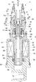
ボディ5の軸線方向中間部には主弁孔18と第1ガイド孔73とが同軸状に設けられ、その主弁孔18と第1ガイド孔73との間にポート14が設けられている。ボディ5は、主弁孔18のポート14とは反対側にて拡径されるとともに、第1ガイド孔73のポート14とは反対側にて拡径されている。ボディ5の下部は第2ガイド孔74を形成する。
図3および図4は、制御弁の動作を表す図であり、図2に対応する。既に説明した図2は、制御弁の最小容量運転状態を示している。図3は、制御弁のブリード機能を動作させたときの状態を示している。図4は、比較的安定した制御状態を示している。以下においては、図1に基づき、適宜図2〜図4を参照しつつ説明する。
Claims (4)
- 吸入室に導入される冷媒を圧縮して吐出室から吐出する可変容量圧縮機の吐出容量を、前記吐出室からクランク室に導入する冷媒の流量を制御することにより変化させる可変容量圧縮機用制御弁において、
前記吐出室に連通する吐出圧力室と、前記クランク室に連通するクランク圧力室と、被感知圧力が導入される圧力感知室と、前記吐出圧力室と前記クランク圧力室との間に設けられる主弁孔と、前記吐出圧力室と前記圧力感知室との間に設けられる第1ガイド孔と、前記圧力感知室に設けられる第2ガイド孔と、が形成されたボディと、
一端側に向けて段階的に縮径されることにより一端側が小径とされ他端側が大径とされた段付円筒状の本体を有し、一端側の小径部が前記第1ガイド孔に摺動可能に支持され、前記主弁孔に接離して主弁を開閉する主弁体が設けられる一方、他端側の大径部が前記圧力感知室に配置され、前記第2ガイド孔に摺動可能に支持される摺動部が設けられた弁駆動体と、
感圧部材としてベローズを含み、前記弁駆動体の大径部の内方に収容されるように設けられ、前記吸入室の吸入圧力または前記クランク室のクランク圧力を前記被感知圧力として感知し、その被感知圧力が設定圧力よりも低くなると、前記ベローズが伸長して前記弁駆動体に開弁方向の力を作用させる感圧部と、
前記弁駆動体と作動連結可能に設けられた伝達ロッドと、
前記設定圧力に応じた閉弁方向のソレノイド力を前記伝達ロッドを介して前記弁駆動体に作用させるソレノイドと、
を備えることを特徴とする可変容量圧縮機用制御弁。 - 前記伝達ロッドは、前記弁駆動体の前記主弁体とは反対側の端部に遊嵌され、前記弁駆動体に対して近接方向に駆動されることにより前記弁駆動体と作動連結し、前記弁駆動体に対して離間方向に駆動されることにより前記弁駆動体との作動連結が解除されることを特徴とする請求項1に記載の可変容量圧縮機用制御弁。
- 前記吸入室の吸入圧力を前記被感知圧力として感知する制御弁として構成され、
前記ボディの一端側から、前記クランク室と前記クランク圧力室とを連通させるクランク室連通ポート、前記吐出室と前記吐出圧力室とを連通させる吐出室連通ポート、前記吸入室と前記圧力感知室とを連通させる吸入室連通ポートが設けられていることを特徴とする請求項1又は2に記載の可変容量圧縮機用制御弁。 - 前記弁駆動体の内方に形成され、前記クランク室連通ポートと前記吸入室連通ポートとを連通させるための内部通路と、
前記内部通路に設けられた副弁を開閉する副弁体をさらに備え、
前記感圧部は、前記副弁体に前記副弁の開閉方向の駆動力を付与可能であることを特徴とする請求項3に記載の可変容量圧縮機用制御弁。
Priority Applications (2)
| Application Number | Priority Date | Filing Date | Title |
|---|---|---|---|
| JP2012223087A JP6064124B2 (ja) | 2012-10-05 | 2012-10-05 | 可変容量圧縮機用制御弁 |
| KR1020130117772A KR102046660B1 (ko) | 2012-10-05 | 2013-10-02 | 가변 용량 압축기용 제어 밸브 |
Applications Claiming Priority (1)
| Application Number | Priority Date | Filing Date | Title |
|---|---|---|---|
| JP2012223087A JP6064124B2 (ja) | 2012-10-05 | 2012-10-05 | 可変容量圧縮機用制御弁 |
Publications (2)
| Publication Number | Publication Date |
|---|---|
| JP2014074472A JP2014074472A (ja) | 2014-04-24 |
| JP6064124B2 true JP6064124B2 (ja) | 2017-01-25 |
Family
ID=50652628
Family Applications (1)
| Application Number | Title | Priority Date | Filing Date |
|---|---|---|---|
| JP2012223087A Active JP6064124B2 (ja) | 2012-10-05 | 2012-10-05 | 可変容量圧縮機用制御弁 |
Country Status (2)
| Country | Link |
|---|---|
| JP (1) | JP6064124B2 (ja) |
| KR (1) | KR102046660B1 (ja) |
Families Citing this family (2)
| Publication number | Priority date | Publication date | Assignee | Title |
|---|---|---|---|---|
| CN107906221B (zh) * | 2017-12-21 | 2023-06-09 | 海杰亚(北京)医疗器械有限公司 | 用于小流量液氮低温系统的两位三通换向阀以及换向方法 |
| CN117781015B (zh) * | 2024-02-26 | 2024-06-07 | 靖江市世嘉电子科技有限公司 | 一种具有过滤组件的气用电磁阀 |
Family Cites Families (6)
| Publication number | Priority date | Publication date | Assignee | Title |
|---|---|---|---|---|
| JP4365691B2 (ja) * | 2004-01-30 | 2009-11-18 | 株式会社テージーケー | 可変容量圧縮機の制御弁 |
| JP2006029304A (ja) * | 2004-07-22 | 2006-02-02 | Tgk Co Ltd | 可変容量圧縮機用制御弁 |
| WO2006129753A1 (ja) * | 2005-06-03 | 2006-12-07 | Eagle Industry Co., Ltd. | 容量制御弁 |
| JP4779095B2 (ja) | 2006-08-21 | 2011-09-21 | 株式会社テージーケー | 可変容量圧縮機用制御弁 |
| JP5369262B2 (ja) * | 2009-08-07 | 2013-12-18 | 株式会社テージーケー | 可変容量圧縮機用制御弁 |
| JP5699259B2 (ja) * | 2011-01-07 | 2015-04-08 | 株式会社テージーケー | 可変容量圧縮機用制御弁 |
-
2012
- 2012-10-05 JP JP2012223087A patent/JP6064124B2/ja active Active
-
2013
- 2013-10-02 KR KR1020130117772A patent/KR102046660B1/ko active Active
Also Published As
| Publication number | Publication date |
|---|---|
| JP2014074472A (ja) | 2014-04-24 |
| KR20140044750A (ko) | 2014-04-15 |
| KR102046660B1 (ko) | 2019-11-19 |
Similar Documents
| Publication | Publication Date | Title |
|---|---|---|
| JP6103586B2 (ja) | 可変容量圧縮機用制御弁 | |
| JP6064131B2 (ja) | 可変容量圧縮機用制御弁 | |
| KR102057345B1 (ko) | 가변 용량 압축기용 제어 밸브 | |
| JP5699259B2 (ja) | 可変容量圧縮機用制御弁 | |
| CN103375381B (zh) | 可变容量压缩机用控制阀 | |
| JP6149206B2 (ja) | 可変容量圧縮機用制御弁 | |
| JP6085789B2 (ja) | 可変容量圧縮機用制御弁 | |
| US20160186733A1 (en) | Control valve for variable displacement compressor | |
| JP2011043102A (ja) | 可変容量圧縮機用制御弁 | |
| JP6216950B2 (ja) | 可変容量圧縮機用制御弁および制御弁 | |
| JP6064124B2 (ja) | 可変容量圧縮機用制御弁 | |
| JP6007368B2 (ja) | 制御弁 | |
| JP6064185B2 (ja) | 可変容量圧縮機用制御弁 | |
| JP6064182B2 (ja) | 可変容量圧縮機用制御弁 | |
| JP6040372B2 (ja) | 可変容量圧縮機用制御弁 | |
| JP6175630B2 (ja) | 制御弁 | |
| JP6175716B2 (ja) | 制御弁 | |
| JP6064181B2 (ja) | 可変容量圧縮機用制御弁 | |
| JP2015200216A (ja) | 可変容量圧縮機用制御弁 | |
| JP2017137797A (ja) | 可変容量圧縮機用制御弁 |
Legal Events
| Date | Code | Title | Description |
|---|---|---|---|
| RD04 | Notification of resignation of power of attorney |
Free format text: JAPANESE INTERMEDIATE CODE: A7424 Effective date: 20141023 |
|
| A521 | Request for written amendment filed |
Free format text: JAPANESE INTERMEDIATE CODE: A523 Effective date: 20141117 |
|
| A621 | Written request for application examination |
Free format text: JAPANESE INTERMEDIATE CODE: A621 Effective date: 20150522 |
|
| RD02 | Notification of acceptance of power of attorney |
Free format text: JAPANESE INTERMEDIATE CODE: A7422 Effective date: 20160208 |
|
| A977 | Report on retrieval |
Free format text: JAPANESE INTERMEDIATE CODE: A971007 Effective date: 20160310 |
|
| A131 | Notification of reasons for refusal |
Free format text: JAPANESE INTERMEDIATE CODE: A131 Effective date: 20160315 |
|
| A521 | Request for written amendment filed |
Free format text: JAPANESE INTERMEDIATE CODE: A523 Effective date: 20160512 |
|
| TRDD | Decision of grant or rejection written | ||
| A01 | Written decision to grant a patent or to grant a registration (utility model) |
Free format text: JAPANESE INTERMEDIATE CODE: A01 Effective date: 20161011 |
|
| A61 | First payment of annual fees (during grant procedure) |
Free format text: JAPANESE INTERMEDIATE CODE: A61 Effective date: 20161017 |
|
| R150 | Certificate of patent or registration of utility model |
Ref document number: 6064124 Country of ref document: JP Free format text: JAPANESE INTERMEDIATE CODE: R150 |
|
| R250 | Receipt of annual fees |
Free format text: JAPANESE INTERMEDIATE CODE: R250 |
|
| R250 | Receipt of annual fees |
Free format text: JAPANESE INTERMEDIATE CODE: R250 |
|
| R250 | Receipt of annual fees |
Free format text: JAPANESE INTERMEDIATE CODE: R250 |
|
| R250 | Receipt of annual fees |
Free format text: JAPANESE INTERMEDIATE CODE: R250 |