JP6061484B2 - Substrate cleaning apparatus and substrate processing apparatus having the same - Google Patents
Substrate cleaning apparatus and substrate processing apparatus having the same Download PDFInfo
- Publication number
- JP6061484B2 JP6061484B2 JP2012072455A JP2012072455A JP6061484B2 JP 6061484 B2 JP6061484 B2 JP 6061484B2 JP 2012072455 A JP2012072455 A JP 2012072455A JP 2012072455 A JP2012072455 A JP 2012072455A JP 6061484 B2 JP6061484 B2 JP 6061484B2
- Authority
- JP
- Japan
- Prior art keywords
- substrate
- cleaning
- filter
- air
- unit
- Prior art date
- Legal status (The legal status is an assumption and is not a legal conclusion. Google has not performed a legal analysis and makes no representation as to the accuracy of the status listed.)
- Expired - Fee Related
Links
Images


Classifications
-
- H—ELECTRICITY
- H01—ELECTRIC ELEMENTS
- H01L—SEMICONDUCTOR DEVICES NOT COVERED BY CLASS H10
- H01L21/00—Processes or apparatus adapted for the manufacture or treatment of semiconductor or solid state devices or of parts thereof
- H01L21/02—Manufacture or treatment of semiconductor devices or of parts thereof
- H01L21/02041—Cleaning
- H01L21/02096—Cleaning only mechanical cleaning
-
- H—ELECTRICITY
- H01—ELECTRIC ELEMENTS
- H01L—SEMICONDUCTOR DEVICES NOT COVERED BY CLASS H10
- H01L21/00—Processes or apparatus adapted for the manufacture or treatment of semiconductor or solid state devices or of parts thereof
- H01L21/67—Apparatus specially adapted for handling semiconductor or electric solid state devices during manufacture or treatment thereof; Apparatus specially adapted for handling wafers during manufacture or treatment of semiconductor or electric solid state devices or components ; Apparatus not specifically provided for elsewhere
- H01L21/67005—Apparatus not specifically provided for elsewhere
- H01L21/67011—Apparatus for manufacture or treatment
- H01L21/67017—Apparatus for fluid treatment
- H01L21/67028—Apparatus for fluid treatment for cleaning followed by drying, rinsing, stripping, blasting or the like
- H01L21/6704—Apparatus for fluid treatment for cleaning followed by drying, rinsing, stripping, blasting or the like for wet cleaning or washing
-
- H—ELECTRICITY
- H01—ELECTRIC ELEMENTS
- H01L—SEMICONDUCTOR DEVICES NOT COVERED BY CLASS H10
- H01L21/00—Processes or apparatus adapted for the manufacture or treatment of semiconductor or solid state devices or of parts thereof
- H01L21/67—Apparatus specially adapted for handling semiconductor or electric solid state devices during manufacture or treatment thereof; Apparatus specially adapted for handling wafers during manufacture or treatment of semiconductor or electric solid state devices or components ; Apparatus not specifically provided for elsewhere
- H01L21/683—Apparatus specially adapted for handling semiconductor or electric solid state devices during manufacture or treatment thereof; Apparatus specially adapted for handling wafers during manufacture or treatment of semiconductor or electric solid state devices or components ; Apparatus not specifically provided for elsewhere for supporting or gripping
- H01L21/687—Apparatus specially adapted for handling semiconductor or electric solid state devices during manufacture or treatment thereof; Apparatus specially adapted for handling wafers during manufacture or treatment of semiconductor or electric solid state devices or components ; Apparatus not specifically provided for elsewhere for supporting or gripping using mechanical means, e.g. chucks, clamps or pinches
- H01L21/68714—Apparatus specially adapted for handling semiconductor or electric solid state devices during manufacture or treatment thereof; Apparatus specially adapted for handling wafers during manufacture or treatment of semiconductor or electric solid state devices or components ; Apparatus not specifically provided for elsewhere for supporting or gripping using mechanical means, e.g. chucks, clamps or pinches the wafers being placed on a susceptor, stage or support
- H01L21/68728—Apparatus specially adapted for handling semiconductor or electric solid state devices during manufacture or treatment thereof; Apparatus specially adapted for handling wafers during manufacture or treatment of semiconductor or electric solid state devices or components ; Apparatus not specifically provided for elsewhere for supporting or gripping using mechanical means, e.g. chucks, clamps or pinches the wafers being placed on a susceptor, stage or support characterised by a plurality of separate clamping members, e.g. clamping fingers
-
- B—PERFORMING OPERATIONS; TRANSPORTING
- B01—PHYSICAL OR CHEMICAL PROCESSES OR APPARATUS IN GENERAL
- B01D—SEPARATION
- B01D46/00—Filters or filtering processes specially modified for separating dispersed particles from gases or vapours
- B01D46/0002—Casings; Housings; Frame constructions
-
- H—ELECTRICITY
- H01—ELECTRIC ELEMENTS
- H01L—SEMICONDUCTOR DEVICES NOT COVERED BY CLASS H10
- H01L21/00—Processes or apparatus adapted for the manufacture or treatment of semiconductor or solid state devices or of parts thereof
- H01L21/02—Manufacture or treatment of semiconductor devices or of parts thereof
- H01L21/02041—Cleaning
- H01L21/02057—Cleaning during device manufacture
-
- H—ELECTRICITY
- H01—ELECTRIC ELEMENTS
- H01L—SEMICONDUCTOR DEVICES NOT COVERED BY CLASS H10
- H01L21/00—Processes or apparatus adapted for the manufacture or treatment of semiconductor or solid state devices or of parts thereof
- H01L21/67—Apparatus specially adapted for handling semiconductor or electric solid state devices during manufacture or treatment thereof; Apparatus specially adapted for handling wafers during manufacture or treatment of semiconductor or electric solid state devices or components ; Apparatus not specifically provided for elsewhere
- H01L21/67005—Apparatus not specifically provided for elsewhere
- H01L21/67011—Apparatus for manufacture or treatment
- H01L21/67017—Apparatus for fluid treatment
- H01L21/67028—Apparatus for fluid treatment for cleaning followed by drying, rinsing, stripping, blasting or the like
- H01L21/6704—Apparatus for fluid treatment for cleaning followed by drying, rinsing, stripping, blasting or the like for wet cleaning or washing
- H01L21/67046—Apparatus for fluid treatment for cleaning followed by drying, rinsing, stripping, blasting or the like for wet cleaning or washing using mainly scrubbing means, e.g. brushes
-
- H—ELECTRICITY
- H01—ELECTRIC ELEMENTS
- H01L—SEMICONDUCTOR DEVICES NOT COVERED BY CLASS H10
- H01L21/00—Processes or apparatus adapted for the manufacture or treatment of semiconductor or solid state devices or of parts thereof
- H01L21/67—Apparatus specially adapted for handling semiconductor or electric solid state devices during manufacture or treatment thereof; Apparatus specially adapted for handling wafers during manufacture or treatment of semiconductor or electric solid state devices or components ; Apparatus not specifically provided for elsewhere
- H01L21/67005—Apparatus not specifically provided for elsewhere
- H01L21/67011—Apparatus for manufacture or treatment
- H01L21/67017—Apparatus for fluid treatment
- H01L21/67028—Apparatus for fluid treatment for cleaning followed by drying, rinsing, stripping, blasting or the like
- H01L21/6704—Apparatus for fluid treatment for cleaning followed by drying, rinsing, stripping, blasting or the like for wet cleaning or washing
- H01L21/67051—Apparatus for fluid treatment for cleaning followed by drying, rinsing, stripping, blasting or the like for wet cleaning or washing using mainly spraying means, e.g. nozzles
-
- H—ELECTRICITY
- H01—ELECTRIC ELEMENTS
- H01L—SEMICONDUCTOR DEVICES NOT COVERED BY CLASS H10
- H01L21/00—Processes or apparatus adapted for the manufacture or treatment of semiconductor or solid state devices or of parts thereof
- H01L21/67—Apparatus specially adapted for handling semiconductor or electric solid state devices during manufacture or treatment thereof; Apparatus specially adapted for handling wafers during manufacture or treatment of semiconductor or electric solid state devices or components ; Apparatus not specifically provided for elsewhere
- H01L21/683—Apparatus specially adapted for handling semiconductor or electric solid state devices during manufacture or treatment thereof; Apparatus specially adapted for handling wafers during manufacture or treatment of semiconductor or electric solid state devices or components ; Apparatus not specifically provided for elsewhere for supporting or gripping
- H01L21/687—Apparatus specially adapted for handling semiconductor or electric solid state devices during manufacture or treatment thereof; Apparatus specially adapted for handling wafers during manufacture or treatment of semiconductor or electric solid state devices or components ; Apparatus not specifically provided for elsewhere for supporting or gripping using mechanical means, e.g. chucks, clamps or pinches
- H01L21/68714—Apparatus specially adapted for handling semiconductor or electric solid state devices during manufacture or treatment thereof; Apparatus specially adapted for handling wafers during manufacture or treatment of semiconductor or electric solid state devices or components ; Apparatus not specifically provided for elsewhere for supporting or gripping using mechanical means, e.g. chucks, clamps or pinches the wafers being placed on a susceptor, stage or support
- H01L21/68742—Apparatus specially adapted for handling semiconductor or electric solid state devices during manufacture or treatment thereof; Apparatus specially adapted for handling wafers during manufacture or treatment of semiconductor or electric solid state devices or components ; Apparatus not specifically provided for elsewhere for supporting or gripping using mechanical means, e.g. chucks, clamps or pinches the wafers being placed on a susceptor, stage or support characterised by a lifting arrangement, e.g. lift pins
-
- H—ELECTRICITY
- H01—ELECTRIC ELEMENTS
- H01L—SEMICONDUCTOR DEVICES NOT COVERED BY CLASS H10
- H01L21/00—Processes or apparatus adapted for the manufacture or treatment of semiconductor or solid state devices or of parts thereof
- H01L21/02—Manufacture or treatment of semiconductor devices or of parts thereof
- H01L21/04—Manufacture or treatment of semiconductor devices or of parts thereof the devices having at least one potential-jump barrier or surface barrier, e.g. PN junction, depletion layer or carrier concentration layer
- H01L21/50—Assembly of semiconductor devices using processes or apparatus not provided for in a single one of the subgroups H01L21/06 - H01L21/326, e.g. sealing of a cap to a base of a container
- H01L21/60—Attaching or detaching leads or other conductive members, to be used for carrying current to or from the device in operation
- H01L2021/60007—Attaching or detaching leads or other conductive members, to be used for carrying current to or from the device in operation involving a soldering or an alloying process
- H01L2021/60022—Attaching or detaching leads or other conductive members, to be used for carrying current to or from the device in operation involving a soldering or an alloying process using bump connectors, e.g. for flip chip mounting
- H01L2021/60097—Applying energy, e.g. for the soldering or alloying process
- H01L2021/60172—Applying energy, e.g. for the soldering or alloying process using static pressure
- H01L2021/60187—Isostatic pressure, e.g. degassing using vacuum or pressurised liquid
Description
本発明は、基板洗浄装置およびそれを備えた基板処理装置に関する。 The present invention relates to a substrate cleaning apparatus and a substrate processing apparatus including the same.
従来より、半導体ウェハ、フォトマスク用ガラス基板、液晶表示装置用ガラス基板、光ディスク用ガラス基板等の基板に種々の処理を行うために、基板処理装置が用いられている。 2. Description of the Related Art Conventionally, a substrate processing apparatus has been used to perform various processes on a substrate such as a semiconductor wafer, a glass substrate for a photomask, a glass substrate for a liquid crystal display device, and a glass substrate for an optical disk.
特許文献1に記載された基板処理装置は、複数の処理室を備える。各処理室の上部にファンフィルタユニットが配置され、各処理室の下部に処理室内排気ダクトが接続される。クリーンルーム内の外気が、ファンフィルタユニットのフィルタを通して各処理室内に供給され、処理室内排気ダクトから排気される。この場合、各処理室内に清浄なダウンフロー(下降流)が形成される。
The substrate processing apparatus described in
しかしながら、処理室内にダウンフローを形成しても、基板へのミスト(微小液滴)およびパーティクルの付着を十分に防止できない場合がある。 However, even if the downflow is formed in the processing chamber, it may not be possible to sufficiently prevent mist (microdroplets) and particles from adhering to the substrate.
例えば、特許文献2に記載された洗浄/乾燥処理ユニットは、スピンプレートを含むスピンチャックを備える。スピンプレートは、基板の外形よりもやや大きい円板形状を有する。スピンチャックにより基板が水平に保持された状態で、スピンプレートが基板の上部に位置する。この場合、洗浄/乾燥処理ユニット内にダウンフローが形成されても、スピンプレートと基板との間の空間には清浄な空気が供給されない。そのため、基板の洗浄処理時および振り切り乾燥処理時には、洗浄液のミストおよびパーティクルが、スピンプレートと基板との間の空間に進入して基板の上面に付着する可能性がある。 For example, the cleaning / drying processing unit described in Patent Document 2 includes a spin chuck including a spin plate. The spin plate has a disk shape that is slightly larger than the outer shape of the substrate. With the substrate held horizontally by the spin chuck, the spin plate is positioned above the substrate. In this case, even if a downflow is formed in the cleaning / drying processing unit, clean air is not supplied to the space between the spin plate and the substrate. Therefore, during the substrate cleaning process and the shake-off drying process, mist and particles of the cleaning liquid may enter the space between the spin plate and the substrate and adhere to the upper surface of the substrate.
本発明の目的は、基板の上面を清浄に保ちつつ基板の下面を洗浄することを可能にする基板洗浄装置およびそれを備える基板処理装置を提供することである。 An object of the present invention is to provide a substrate cleaning apparatus and a substrate processing apparatus including the substrate cleaning apparatus that can clean the lower surface of the substrate while keeping the upper surface of the substrate clean.
(1)第1の発明に係る基板洗浄装置は、基板の下面を洗浄する基板洗浄装置であって、鉛直方向に沿う回転軸線の周りで回転可能に設けられかつ中央部に開口を有する回転部材と、回転部材の上側に設けられ、回転部材を回転させる回転駆動装置と、回転部材の下側に設けられ、基板の上面が回転部材に対向する状態で基板を保持する保持部材と、保持部材により保持される基板と回転部材との間に、回転部材の開口を通して空気を供給する空気供給機構と、保持部材により保持される基板の下面を洗浄する洗浄機構と、空気供給機構の少なくとも一部、回転部材、回転駆動装置、保持部材および洗浄機構を収容する筐体とを備え、空気供給機構は、フィルタと、フィルタを収容するフィルタ収容部材と、フィルタ収容部材に空気を供給することによりフィルタに空気を通過させる空気供給部と、フィルタを通過した空気を回転部材の開口に導くようにかつフィルタから回転部材の開口へ漸次減少する断面積を有するように複数の部材で構成される空気経路とを含み、複数の部材は、フィルタ収容部材に取り付けられ、第1の断面積を有する第1の流路を形成する第1の部材と、第1の部材に対して取り外し可能に接続され、第1の断面積よりも小さい第2の断面積を有する第2の流路を形成する第2の部材とを含み、フィルタ収容部材は、筐体内の上部に配置され、回転駆動装置の上方に形成された収容部開口と、収容部開口を取り囲むように形成された複数の貫通孔とを有し、フィルタは、空気供給部により供給される空気を上方から下方に通過させるようにフィルタ収容部材内に配置され、空気経路は、フィルタを通過するとともにフィルタ収容部材の収容部開口を通過した一部の空気を回転部材の開口から該回転部材の下方空間に導くように構成され、フィルタを通過した残りの空気は、フィルタ収容部材の複数の貫通孔を通して筐体の底部に向かうように筐体内に供給されるものである。 (1) A substrate cleaning apparatus according to a first aspect of the present invention is a substrate cleaning apparatus that cleans the lower surface of a substrate, and is a rotating member that is rotatably provided around a rotation axis along the vertical direction and has an opening at the center. A rotation drive device that is provided on the upper side of the rotation member and rotates the rotation member, a holding member that is provided on the lower side of the rotation member and holds the substrate in a state where the upper surface of the substrate faces the rotation member, and a holding member An air supply mechanism for supplying air between the substrate held by the rotating member and the rotation member, a cleaning mechanism for cleaning the lower surface of the substrate held by the holding member , and at least a part of the air supply mechanism , the rotating member, the rotary drive device, and a housing for accommodating the holding member and the cleaning mechanism, an air supply mechanism, to supply a filter, and the filter accommodating member for accommodating the filter, the air filter accommodating member Thus, the air supply unit that allows air to pass through the filter, and a plurality of members that have a cross-sectional area that gradually reduces the air passing through the filter to the opening of the rotating member and from the filter to the opening of the rotating member. A plurality of members attached to the filter housing member and detachable from the first member and forming a first flow path having a first cross-sectional area. connected, seen including a second member forming a second flow path having a second cross-sectional area smaller than the first cross-sectional area, the filter accommodating member is disposed on the housing, rotary drive The filter has a housing opening formed above the apparatus and a plurality of through holes formed so as to surround the housing opening, and the filter allows air supplied by the air supply section to pass from above to below. Filter housing And the air path is configured to guide part of the air that has passed through the filter and passed through the housing opening of the filter housing member from the opening of the rotating member to the lower space of the rotating member, and passes through the filter. The remaining air is supplied into the housing so as to go to the bottom of the housing through the plurality of through holes of the filter housing member .
その基板洗浄装置においては、空気供給部によりフィルタに空気が供給される。フィルタを通過した清浄な空気が、空気経路により回転部材の中央部に形成された開口に導かれる。 In the substrate cleaning apparatus, air is supplied to the filter by the air supply unit. Clean air that has passed through the filter is guided to an opening formed in the center of the rotating member by an air path.
保持部材により基板が保持されることにより、基板の上面が回転部材に対向する。それにより、回転部材の開口に導かれた清浄な空気が、保持部材により保持される基板の中心に向かって供給される。この状態で、回転駆動装置により鉛直方向に沿う回転軸線の周りで回転部材が回転し、回転する基板の下面が洗浄機構により洗浄される。 When the substrate is held by the holding member, the upper surface of the substrate faces the rotating member. Thereby, the clean air guided to the opening of the rotating member is supplied toward the center of the substrate held by the holding member. In this state, the rotating member rotates around the rotation axis along the vertical direction by the rotation driving device, and the lower surface of the rotating substrate is cleaned by the cleaning mechanism.
この場合、基板の上面上では基板の中心から基板の外周端部に向かう清浄な空気の流れが形成される。それにより、保持部材により保持される基板と回転部材との間に処理液の液滴またはパーティクル等を含む雰囲気が流入することが防止される。その結果、基板の上面を清浄に保ちつつ基板の下面を洗浄することが可能となる。
また、空気経路は、フィルタから回転部材の開口へ漸次減少する断面積を有するように構成されている。
この場合、空気経路の断面積がフィルタから回転部材の開口へ漸次減少するので、フィルタを通過する空気の流速に比べて回転部材の開口を通過する空気の流速を大きくすることができる。それにより、基板と回転部材との間に十分な量の空気が供給されるので、基板の上面上で基板の中心から基板の外周端部に向かう清浄な空気の流れが確実に形成される。
In this case, a clean air flow from the center of the substrate toward the outer peripheral edge of the substrate is formed on the upper surface of the substrate. This prevents an atmosphere containing droplets or particles of processing liquid from flowing between the substrate held by the holding member and the rotating member. As a result, it is possible to clean the lower surface of the substrate while keeping the upper surface of the substrate clean.
The air path is configured to have a cross-sectional area that gradually decreases from the filter to the opening of the rotating member.
In this case, since the cross-sectional area of the air path gradually decreases from the filter to the opening of the rotating member, the flow velocity of the air passing through the opening of the rotating member can be made larger than the flow velocity of air passing through the filter. Thereby, since a sufficient amount of air is supplied between the substrate and the rotating member, a clean air flow from the center of the substrate toward the outer peripheral end of the substrate is reliably formed on the upper surface of the substrate.
基板洗浄装置は、空気供給機構の少なくとも一部、回転部材、回転駆動装置、保持部材および洗浄機構を収容する筐体をさらに備え、フィルタ収容部材は、筐体内の上部に配置され、回転駆動装置の上方に形成された収容部開口と、前記収容部開口を取り囲むように形成された複数の貫通孔とを有し、フィルタは、空気供給部により供給される空気を上方から下方に通過させるようにフィルタ収容部材内に配置され、空気経路は、フィルタを通過するとともにフィルタ収容部材の収容部開口を通過した一部の空気を回転部材の開口から該回転部材の下方空間に導くように構成され、フィルタを通過した残りの空気は、フィルタ収容部材の複数の貫通孔を通して筐体の底部に向かうように筐体内に供給される。 Board cleaning apparatus, at least a part of the air supply mechanism, the rotary member, the rotary drive device further comprises a housing for accommodating the holding member and the cleaning mechanism, the filter accommodating member is disposed on the housing, rotary drive A housing opening formed above the apparatus and a plurality of through holes formed so as to surround the housing opening, and the filter allows air supplied by the air supply section to pass from above to below. disposed in the filter accommodating member as the air pathway, constitutes a part of the air passing through the housing opening of the filter accommodating member while passing through the filter from the opening of the rotating member so as to guide the lower space of the rotary member is, the remaining air passing through the filter, Ru is supplied to the housing so as to be directed through the plurality of through holes of the filter accommodating member to the bottom of the housing.
この場合、筐体内の上部に配置されたフィルタを通過した一部の空気が、フィルタ収容部材の収容部開口を通して保持部材により保持される基板と回転部材との間に供給される。また、フィルタを通過した残りの空気が、フィルタ収容部材の複数の貫通孔を通して筐体内の上部から筐体内に供給される。 In this case, a part of the air that has passed through the filter disposed in the upper part of the housing is supplied between the substrate held by the holding member and the rotating member through the opening of the filter housing member . Further, the remaining air that has passed through the filter is supplied into the housing from the upper portion of the housing through the plurality of through holes of the filter housing member .
それにより、基板の上面上で基板の中心から基板の外周端部に向かう清浄な空気の流れが形成されるとともに、筐体内に上部から下部に向かう清浄な空気の流れが形成される。したがって、基板の上面を清浄に保ちつつ筐体内で処理液の液滴またはパーティクル等が飛散することを抑制することが可能となる。 Thereby, a clean air flow from the center of the substrate toward the outer peripheral edge of the substrate is formed on the upper surface of the substrate, and a clean air flow from the upper part to the lower part is formed in the housing. Therefore, it is possible to suppress the droplets or particles of the processing liquid from scattering in the housing while keeping the upper surface of the substrate clean.
(2)空気供給部は、フィルタの上側に設けられ、筐体の外部から供給される空気をフィルタに導くダクトを含んでもよい。 ( 2 ) The air supply unit may include a duct that is provided on the upper side of the filter and guides air supplied from the outside of the housing to the filter.
この場合、筐体の外部から供給される空気を、ダクトを通してフィルタの上方から下方に容易に通過させることができる。それにより、フィルタを通過した残りの空気を用いて、筐体内で上部から下部に向かう清浄な空気の流れを容易に形成することができる。 In this case, the air supplied from the outside of the housing can be easily passed from the upper side to the lower side of the filter through the duct. As a result, a clean air flow from the upper part to the lower part can be easily formed in the housing using the remaining air that has passed through the filter.
(3)第2の部材は、第1の部材に対して水平方向に取り外し可能に構成されてもよい。 ( 3 ) The second member may be configured to be removable in the horizontal direction with respect to the first member.
(4)回転駆動装置は、複数の部材のうちの1つとして空気経路の一部を構成しかつ鉛直方向に延びる中空の回転軸を有し、回転部材は、回転軸の内部空間が回転部材の開口を通して回転部材の下方の空間に連通するように、回転軸の下端部に取り付けられてもよい。 ( 4 ) The rotary drive device has a hollow rotary shaft that forms part of the air path and extends in the vertical direction as one of the plurality of members, and the rotary member has a rotary member whose internal space is the rotary member. It may be attached to the lower end of the rotating shaft so as to communicate with the space below the rotating member through the opening.
この場合、保持部材により基板が保持された状態で、フィルタを通過した清浄な空気が、回転軸の内部空間を通して基板と回転部材との間に供給される。このように、回転駆動装置の回転軸が空気経路の一部を構成することにより、複雑な構成を用いることなく回転部材の開口に清浄な空気を導くことができる。 In this case, with the substrate held by the holding member, clean air that has passed through the filter is supplied between the substrate and the rotating member through the internal space of the rotating shaft. As described above, the rotation shaft of the rotation drive device forms a part of the air path, so that clean air can be guided to the opening of the rotation member without using a complicated configuration.
(5)洗浄機構は、保持部材により保持される基板の下面を洗浄するための洗浄具と、保持部材により保持される基板の下面に洗浄液を供給する洗浄液供給部とを備えてもよい。 ( 5 ) The cleaning mechanism may include a cleaning tool for cleaning the lower surface of the substrate held by the holding member, and a cleaning liquid supply unit that supplies the cleaning liquid to the lower surface of the substrate held by the holding member.
この場合、保持部材により保持される基板の下面に洗浄液が供給されるとともに、その基板の下面が洗浄具により確実に洗浄される。 In this case, the cleaning liquid is supplied to the lower surface of the substrate held by the holding member, and the lower surface of the substrate is reliably cleaned by the cleaning tool.
基板の下面の洗浄時には、基板に供給された洗浄液の液滴が基板周辺の空間で飛散する。このような場合でも、基板の上面上で基板の中心から基板の外周端部に向かう清浄な空気の流れが形成されるので、基板の上面に洗浄液の液滴が付着することが確実に防止される。 When cleaning the lower surface of the substrate, droplets of the cleaning liquid supplied to the substrate are scattered in the space around the substrate. Even in such a case, a clean air flow from the center of the substrate to the outer peripheral edge of the substrate is formed on the upper surface of the substrate, so that the droplets of the cleaning liquid are reliably prevented from adhering to the upper surface of the substrate. The
(6)第2の発明に係る基板処理装置は、露光装置に隣接するように配置され、基板に処理を行う基板処理装置であって、基板に処理を行うための処理部と、処理部と露光装置との間で基板の受け渡しを行うための受け渡し部とを備え、処理部および受け渡し部の少なくとも一方は、基板の下面を洗浄する上記の基板洗浄装置とを含むものである。 ( 6 ) A substrate processing apparatus according to a second aspect of the present invention is a substrate processing apparatus that is disposed adjacent to an exposure apparatus and performs processing on a substrate, a processing unit for performing processing on the substrate, a processing unit, A transfer unit for transferring the substrate to and from the exposure apparatus, and at least one of the processing unit and the transfer unit includes the substrate cleaning apparatus described above for cleaning the lower surface of the substrate.
その基板処理装置においては、処理部により基板に所定の処理が行われ、受け渡し部により処理部と露光装置との間で基板の受け渡しが行われる。処理部および受け渡し部の少なくとも一方には、上記の基板洗浄装置が含まれる。 In the substrate processing apparatus, predetermined processing is performed on the substrate by the processing unit, and the substrate is transferred between the processing unit and the exposure apparatus by the transfer unit. At least one of the processing unit and the delivery unit includes the substrate cleaning apparatus.
その基板洗浄装置においては、基板の上面を清浄に保ちつつ基板の下面を洗浄することが可能である。それにより、基板の上面および下面が汚染されることに起因する基板の処理不良の発生を防止することができる。 In the substrate cleaning apparatus, it is possible to clean the lower surface of the substrate while keeping the upper surface of the substrate clean. Accordingly, it is possible to prevent occurrence of processing defects on the substrate due to contamination of the upper and lower surfaces of the substrate.
(7)処理部は、基板の上面に感光性材料からなる感光性膜を形成するように構成された感光性膜形成ユニットを含み、基板洗浄装置は、感光性膜形成ユニットによる感光性膜の形成後かつ露光装置による露光処理前または露光処理後の基板の下面を洗浄するように構成されてもよい。 ( 7 ) The processing unit includes a photosensitive film forming unit configured to form a photosensitive film made of a photosensitive material on the upper surface of the substrate, and the substrate cleaning apparatus includes a photosensitive film forming unit configured to form a photosensitive film by the photosensitive film forming unit. You may comprise so that the lower surface of the board | substrate after formation and before the exposure process by an exposure apparatus or after an exposure process may be wash | cleaned.
この場合、感光性膜形成ユニットによる感光性膜の形成後かつ露光装置による露光処理前または露光処理後の基板の下面が基板洗浄装置により洗浄される。基板洗浄装置による基板の洗浄時には基板の上面が清浄に保たれる。それにより、基板の上面に形成される感光性膜の汚染が防止される。 In this case, the lower surface of the substrate after the formation of the photosensitive film by the photosensitive film forming unit and before or after the exposure processing by the exposure apparatus is cleaned by the substrate cleaning apparatus. When the substrate is cleaned by the substrate cleaning apparatus, the upper surface of the substrate is kept clean. Thereby, contamination of the photosensitive film formed on the upper surface of the substrate is prevented.
本発明によれば、基板の上面を清浄に保ちつつ基板の下面を洗浄することが可能となる。 According to the present invention, it is possible to clean the lower surface of the substrate while keeping the upper surface of the substrate clean.
以下、本発明の実施の形態に係る基板洗浄装置およびそれを備えた基板処理装置について図面を用いて説明する。以下の説明において、基板とは、半導体基板、液晶表示装置用基板、プラズマディスプレイ用基板、フォトマスク用ガラス基板、光ディスク用基板、磁気ディスク用基板、光磁気ディスク用基板、フォトマスク用基板等をいう。本実施の形態では、基板洗浄装置の一例として、露光処理前の基板の裏面の洗浄処理を行う裏面洗浄処理ユニットを説明する。 Hereinafter, a substrate cleaning apparatus and a substrate processing apparatus including the same according to embodiments of the present invention will be described with reference to the drawings. In the following description, the substrate refers to a semiconductor substrate, a liquid crystal display substrate, a plasma display substrate, a photomask glass substrate, an optical disk substrate, a magnetic disk substrate, a magneto-optical disk substrate, a photomask substrate, and the like. Say. In the present embodiment, as an example of a substrate cleaning apparatus, a back surface cleaning unit that performs a cleaning process on the back surface of a substrate before exposure processing will be described.
(1)基板処理装置の構成
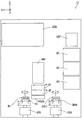
図1は、本発明の一実施の形態に係る基板処理装置の平面図である。本実施の形態に係る基板処理装置500は、例えばクリーンルーム内に設置される。なお、図1ならびに後述する図2〜図4には、位置関係を明確にするために互いに直交するX方向、Y方向およびZ方向を示す矢印を付している。X方向およびY方向は水平面内で互いに直交し、Z方向は鉛直方向に相当する。
(1) Configuration of Substrate Processing Apparatus FIG. 1 is a plan view of a substrate processing apparatus according to an embodiment of the present invention. The
図1に示すように、基板処理装置500は、インデクサブロック9、反射防止膜用処理ブロック10、レジスト膜用処理ブロック11、現像処理ブロック12およびインターフェースブロック15を含む。また、インターフェースブロック15に隣接するように露光装置16が配置される。露光装置16においては、基板Wに露光処理が行われる。
As shown in FIG. 1, the
インデクサブロック9は、メインコントローラ(制御部)30、複数のキャリア載置台40およびインデクサロボットIRを含む。メインコントローラ30は、インデクサブロック9、反射防止膜用処理ブロック10、レジスト膜用処理ブロック11、現像処理ブロック12およびインターフェースブロック15の動作を制御する。インデクサロボットIRには、基板Wを受け渡すためのハンドIRHが設けられる。
The
反射防止膜用処理ブロック10は、反射防止膜用熱処理部100,101、反射防止膜用塗布処理部50および第1のセンターロボットCR1を含む。反射防止膜用塗布処理部50は、第1のセンターロボットCR1を挟んで反射防止膜用熱処理部100,101に対向して設けられる。第1のセンターロボットCR1には、基板Wを受け渡すためのハンドCRH1,CRH2が上下に設けられる。
The antireflection
インデクサブロック9と反射防止膜用処理ブロック10との間には、雰囲気遮断用の隔壁17が設けられる。この隔壁17には、インデクサブロック9と反射防止膜用処理ブロック10との間で基板Wの受け渡しを行うための基板載置部PASS1,PASS2が上下に近接して設けられる。上側の基板載置部PASS1は、基板Wをインデクサブロック9から反射防止膜用処理ブロック10へ搬送する際に用いられ、下側の基板載置部PASS2は、基板Wを反射防止膜用処理ブロック10からインデクサブロック9へ搬送する際に用いられる。
A
また、基板載置部PASS1,PASS2には、基板Wの有無を検出する光学式のセンサ(図示せず)が設けられている。それにより、基板載置部PASS1,PASS2において基板Wが載置されているか否かの判定を行うことが可能となる。また、基板載置部PASS1,PASS2には、固定設置された複数本の支持ピンが設けられている。なお、上記の光学式のセンサおよび支持ピンは、後述する基板載置部PASS3〜PASS9にも同様に設けられる。 The substrate platforms PASS1, PASS2 are provided with optical sensors (not shown) that detect the presence or absence of the substrate W. Thereby, it is possible to determine whether or not the substrate W is placed on the substrate platforms PASS1 and PASS2. The substrate platforms PASS1, PASS2 are provided with a plurality of support pins fixedly installed. The optical sensor and the support pin are also provided in the same manner on the substrate platforms PASS3 to PASS9 described later.
レジスト膜用処理ブロック11は、レジスト膜用熱処理部110,111、レジスト膜用塗布処理部60および第2のセンターロボットCR2を含む。レジスト膜用塗布処理部60は、第2のセンターロボットCR2を挟んでレジスト膜用熱処理部110,111に対向して設けられる。第2のセンターロボットCR2には、基板Wを受け渡すためのハンドCRH3,CRH4が上下に設けられる。
The resist
反射防止膜用処理ブロック10とレジスト膜用処理ブロック11との間には、雰囲気遮断用の隔壁18が設けられる。この隔壁18には、反射防止膜用処理ブロック10とレジスト膜用処理ブロック11との間で基板Wの受け渡しを行うための基板載置部PASS3,PASS4が上下に近接して設けられる。上側の基板載置部PASS3は、基板Wを反射防止膜用処理ブロック10からレジスト膜用処理ブロック11へ搬送する際に用いられ、下側の基板載置部PASS4は、基板Wをレジスト膜用処理ブロック11から反射防止膜用処理ブロック10へ搬送する際に用いられる。
A
現像処理ブロック12は、現像用熱処理部120、露光後ベーク用熱処理部121、現像処理部70および第3のセンターロボットCR3を含む。露光後ベーク用熱処理部121はインターフェースブロック15に隣接し、後述するように、基板載置部PASS7,PASS8を備える。現像処理部70は第3のセンターロボットCR3を挟んで現像用熱処理部120および露光後ベーク用熱処理部121に対向して設けられる。第3のセンターロボットCR3には、基板Wを受け渡すためのハンドCRH5,CRH6が上下に設けられる。
The
レジスト膜用処理ブロック11と現像処理ブロック12との間には、雰囲気遮断用の隔壁19が設けられる。この隔壁19には、レジスト膜用処理ブロック11と現像処理ブロック12との間で基板Wの受け渡しを行うための基板載置部PASS5,PASS6が上下に近接して設けられる。上側の基板載置部PASS5は、基板Wをレジスト膜用処理ブロック11から現像処理ブロック12へ搬送する際に用いられ、下側の基板載置部PASS6は、基板Wを現像処理ブロック12からレジスト膜用処理ブロック11へ搬送する際に用いられる。
A
インターフェースブロック15は、送りバッファ部SBF、裏面洗浄処理ユニットBC、第4のセンターロボットCR4、エッジ露光部EEW、戻りバッファ部RBF、載置兼冷却ユニットPASS−CP(以下、P−CPと略記する)、基板載置部PASS9およびインターフェース用搬送機構IFRを含む。
The
裏面洗浄処理ユニットBCは、露光処理前の基板Wの裏面の洗浄処理(以下、裏面洗浄処理と呼ぶ)を行う。ここで、基板Wの上面とは上方に向けられた基板Wの面をいい、基板Wの下面とは下方に向けられた基板Wの面をいう。また、基板Wの表面とは、反射防止膜用処理ブロック10およびレジスト膜用処理ブロック11において反射防止膜およびレジスト膜が形成される面(主面)をいい、基板Wの裏面とは、その反対側の面をいう。本実施の形態に係る基板処理装置500の内部では、基板Wの表面が上方に向けられた状態で、基板Wに各種の処理が行われる。
The back surface cleaning unit BC performs a back surface cleaning process (hereinafter referred to as a back surface cleaning process) of the substrate W before the exposure process. Here, the upper surface of the substrate W refers to the surface of the substrate W directed upward, and the lower surface of the substrate W refers to the surface of the substrate W directed downward. Further, the surface of the substrate W refers to the surface (main surface) on which the antireflection film and the resist film are formed in the antireflection
裏面洗浄処理ユニットBCは、基板の外周端部を保持する端部保持式のスピンチャック600(後述する図5)を備える。スピンチャック600は、中央部に開口520hが形成されたスピンプレート520(後述する図5)を含む。スピンチャック600により基板Wが保持されることにより、基板Wの上面(本例では基板Wの表面)がスピンプレート520に対向する。この状態で、スピンプレート520の開口520hから基板Wとスピンプレート520との間に、ULPA(Ultra Low Penetration Air )フィルタF(後述する図5)を通過した空気が供給され、基板Wの下面(本例では基板Wの裏面)が洗浄される。裏面洗浄処理ユニットBCの詳細は後述する。
The back surface cleaning processing unit BC includes an end holding
第4のセンターロボットCR4には、基板Wを受け渡すためのハンドCRH7,CRH8(図4)が上下に設けられ、インターフェース用搬送機構IFRには、基板Wを受け渡すためのハンドH1,H2(図4)が上下に設けられる。インターフェースブロック15の詳細については後述する。
The fourth central robot CR4 is provided with hands CRH7 and CRH8 (FIG. 4) for delivering the substrate W up and down, and the interface transport mechanism IFR has hands H1 and H2 (for delivering the substrate W). 4) is provided at the top and bottom. Details of the
本実施の形態に係る基板処理装置500においては、Y方向に沿ってインデクサブロック9、反射防止膜用処理ブロック10、レジスト膜用処理ブロック11、現像処理ブロック12およびインターフェースブロック15が順に並設されている。
In the
図2は、図1の基板処理装置500の一方の概略側面図であり、図3は、図1の基板処理装置500の他方の概略側面図である。なお、図2においては、基板処理装置500の一側方に設けられるものを主に示し、図3においては、基板処理装置500の他側方に設けられるものを主に示している。
2 is a schematic side view of one side of the
まず、図2を用いて、基板処理装置500の構成について説明する。図2に示すように、反射防止膜用処理ブロック10の反射防止膜用塗布処理部50(図1)には、3個の塗布ユニットBARCが上下に積層配置されている。各塗布ユニットBARCは、基板Wを水平姿勢で吸着保持して回転するスピンチャック51およびスピンチャック51上に保持された基板Wに反射防止膜の塗布液を供給する供給ノズル52を備える。
First, the configuration of the
レジスト膜用処理ブロック11のレジスト膜用塗布処理部60(図1)には、3個の塗布ユニットRESが上下に積層配置されている。各塗布ユニットRESは、基板Wを水平姿勢で吸着保持して回転するスピンチャック61およびスピンチャック61上に保持された基板Wにレジスト膜の塗布液を供給する供給ノズル62を備える。
In the resist film coating processing section 60 (FIG. 1) of the resist
現像処理ブロック12の現像処理部70(図1)には、5個の現像処理ユニットDEVが上下に積層配置されている。各現像処理ユニットDEVは、基板Wを水平姿勢で吸着保持して回転するスピンチャック71およびスピンチャック71上に保持された基板Wに現像液を供給する供給ノズル72を備える。
In the development processing unit 70 (FIG. 1) of the
インターフェースブロック15内の一側方側には、エッジ露光部EEWが配置されている。エッジ露光部EEWは、基板Wを水平姿勢で吸着保持して回転するスピンチャック98およびスピンチャック98上に保持された基板Wの周縁を露光する光照射器99を備える。
An edge exposure unit EEW is disposed on one side of the
次に、図3を用いて、基板処理装置500の構成について説明する。図3に示すように、反射防止膜用処理ブロック10の反射防止膜用熱処理部100,101には、2個の加熱ユニット(ホットプレート)HPおよび2個の冷却ユニット(クーリングプレート)CPがそれぞれ積層配置される。また、反射防止膜用熱処理部100,101には、最上部に加熱ユニットHPおよび冷却ユニットCPの温度を制御するローカルコントローラLCが各々配置される。
Next, the configuration of the
レジスト膜用処理ブロック11のレジスト膜用熱処理部110,111には、2個の加熱ユニットHPおよび2個の冷却ユニットCPがそれぞれ積層配置される。また、レジスト膜用熱処理部110,111には、最上部に加熱ユニットHPおよび冷却ユニットCPの温度を制御するローカルコントローラLCが各々配置される。
Two heating units HP and two cooling units CP are stacked in the resist film
現像処理ブロック12の現像用熱処理部120には、2個の加熱ユニットHPおよび2個の冷却ユニットCPが積層配置され、露光後ベーク用熱処理部121には2個の加熱ユニットHP、2個の冷却ユニットCPおよび基板載置部PASS7,PASS8が上下に積層配置される。また、現像用熱処理部120および露光後ベーク用熱処理部121には、最上部に加熱ユニットHPおよび冷却ユニットCPの温度を制御するローカルコントローラLCが各々配置される。
The development
次に、図4を用いてインターフェースブロック15について詳細に説明する。図4は、図1の露光装置16の位置から見たインターフェースブロック15の概略側面図である。図4に示すように、インターフェースブロック15内において、一側方には、送りバッファ部SBFおよび3個の裏面洗浄処理ユニットBCが積層配置される。また、インターフェースブロック15内において、他側方の上部には、エッジ露光部EEWが配置される。
Next, the
エッジ露光部EEWの下方において、インターフェースブロック15内の略中央部には、戻りバッファ部RBF、2個の載置兼冷却ユニットP−CPおよび基板載置部PASS9が上下に積層配置される。
Below the edge exposure unit EEW, a return buffer unit RBF, two placement / cooling units P-CP, and a substrate platform PASS9 are stacked in a vertical direction at a substantially central portion in the
また、インターフェースブロック15内の下部には、第4のセンターロボットCR4およびインターフェース用搬送機構IFRが設けられている。第4のセンターロボットCR4は、送りバッファ部SBF、裏面洗浄処理ユニットBC、エッジ露光部EEW、戻りバッファ部RBF、載置兼冷却ユニットP−CPおよび基板載置部PASS9の間で鉛直方向に移動可能かつ回転可能に設けられている。インターフェース用搬送機構IFRは、戻りバッファ部RBF、載置兼冷却ユニットP−CPおよび基板載置部PASS9の間で鉛直方向に移動可能かつ回転可能に設けられている。
In the lower part of the
(2)基板処理装置の動作
次に、本実施の形態に係る基板処理装置500の動作について図1〜図4を参照しながら説明する。
(2) Operation of Substrate Processing Apparatus Next, the operation of the
(2−1)インデクサブロックから現像処理ブロックまでの動作
まず、インデクサブロック9から現像処理ブロック12までの動作について簡単に説明する。
(2-1) Operation from the indexer block to the development processing block First, the operation from the
インデクサブロック9のキャリア載置台40の上には、複数枚の基板Wを多段に収納するキャリアCが搬入される。インデクサロボットIRは、ハンドIRHを用いてキャリアC内に収納された未処理の基板Wを取り出す。その後、インデクサロボットIRはX方向に移動しつつZ方向に平行な軸の周りで回転移動し、未処理の基板Wを基板載置部PASS1に載置する。
On the carrier mounting table 40 of the
基板載置部PASS1に載置された未処理の基板Wは、反射防止膜用処理ブロック10の第1のセンターロボットCR1により受け取られる。第1のセンターロボットCR1は、その基板Wを反射防止膜用熱処理部100,101に搬入する。
The unprocessed substrate W placed on the substrate platform PASS1 is received by the first central robot CR1 of the antireflection
その後、第1のセンターロボットCR1は、反射防止膜用熱処理部100,101から熱処理済みの基板Wを取り出し、その基板Wを反射防止膜用塗布処理部50に搬入する。この反射防止膜用塗布処理部50では、露光時に発生する定在波やハレーションを減少させるために、塗布ユニットBARCにより基板W上に反射防止膜が塗布形成される。
Thereafter, the first central robot CR1 takes out the heat-treated substrate W from the antireflection film
次に、第1のセンターロボットCR1は、反射防止膜用塗布処理部50から塗布処理済みの基板Wを取り出し、その基板Wを反射防止膜用熱処理部100,101に搬入する。その後、第1のセンターロボットCR1は、反射防止膜用熱処理部100,101から熱処理済みの基板Wを取り出し、その基板Wを基板載置部PASS3に載置する。
Next, the first central robot CR1 takes out the coated substrate W from the antireflection film
基板載置部PASS3に載置された基板Wは、レジスト膜用処理ブロック11の第2のセンターロボットCR2により受け取られる。第2のセンターロボットCR2は、その基板Wをレジスト膜用熱処理部110,111に搬入する。
The substrate W placed on the substrate platform PASS3 is received by the second central robot CR2 of the resist
その後、第2のセンターロボットCR2は、レジスト膜用熱処理部110,111から熱処理済みの基板Wを取り出し、その基板Wをレジスト膜用塗布処理部60に搬入する。このレジスト膜用塗布処理部60では、塗布ユニットRESにより反射防止膜が塗布形成された基板W上にレジスト膜が塗布形成される。
Thereafter, the second central robot CR2 takes out the heat-treated substrate W from the resist film
次に、第2のセンターロボットCR2は、レジスト膜用塗布処理部60から塗布処理済みの基板Wを取り出し、その基板Wをレジスト膜用熱処理部110,111に搬入する。その後、第2のセンターロボットCR2は、レジスト膜用熱処理部110,111から熱処理済みの基板Wを取り出し、その基板Wを基板載置部PASS5に載置する。
Next, the second central robot CR2 takes out the coated substrate W from the resist film
基板載置部PASS5に載置された基板Wは、現像処理ブロック12の第3のセンターロボットCR3により受け取られる。第3のセンターロボットCR3は、その基板Wを基板載置部PASS7に載置する。
The substrate W placed on the substrate platform PASS5 is received by the third central robot CR3 of the
基板載置部PASS7に載置された基板Wは、インターフェースブロック15の第4のセンターロボットCR4により受け取られ、後述するように、インターフェースブロック15および露光装置16において所定の処理が施される。インターフェースブロック15および露光装置16において基板Wに所定の処理が施された後、その基板Wは、第4のセンターロボットCR4により現像処理ブロック12の露光後ベーク用熱処理部121に搬入される。
The substrate W placed on the substrate platform PASS7 is received by the fourth central robot CR4 of the
露光後ベーク用熱処理部121においては、基板Wに対して露光後ベーク(PEB)が行われる。その後、第4のセンターロボットCR4は、露光後ベーク用熱処理部121から基板Wを取り出し、その基板Wを基板載置部PASS8に載置する。
In the post-exposure baking
基板載置部PASS8に載置された基板Wは、現像処理ブロック12の第3のセンターロボットCR3により受け取られる。第3のセンターロボットCR3は、その基板Wを現像処理部70に搬入する。現像処理部70においては、露光された基板Wに対して現像処理が施される。
The substrate W placed on the substrate platform PASS8 is received by the third central robot CR3 of the
次に、第3のセンターロボットCR3は、現像処理部70から現像処理済みの基板Wを取り出し、その基板Wを現像用熱処理部120に搬入する。その後、第3のセンターロボットCR3は、現像用熱処理部120から熱処理後の基板Wを取り出し、その基板Wを基板載置部PASS6に載置する。
Next, the third central robot CR3 takes out the development-processed substrate W from the
基板載置部PASS6に載置された基板Wは、レジスト膜用処理ブロック11の第2のセンターロボットCR2により基板載置部PASS4に載置される。基板載置部PASS4に載置された基板Wは反射防止膜用処理ブロック10の第1のセンターロボットCR1により基板載置部PASS2に載置される。
The substrate W placed on the substrate platform PASS6 is placed on the substrate platform PASS4 by the second central robot CR2 of the resist
基板載置部PASS2に載置された基板Wは、インデクサブロック9のインデクサロボットIRによりキャリアC内に収納される。これにより、基板処理装置500における基板Wの各処理が終了する。
The substrate W placed on the substrate platform PASS 2 is stored in the carrier C by the indexer robot IR of the
(2−2)インターフェースブロックの動作
次に、インターフェースブロック15の動作について詳細に説明する。
(2-2) Operation of Interface Block Next, the operation of the
上記のように、インデクサブロック9に搬入された基板Wは、所定の処理を施された後、現像処理ブロック12(図1)の基板載置部PASS7に載置される。
As described above, the substrate W carried into the
基板載置部PASS7に載置された基板Wは、インターフェースブロック15の第4のセンターロボットCR4により受け取られる。第4のセンターロボットCR4は、その基板Wをエッジ露光部EEW(図4)に搬入する。このエッジ露光部EEWにおいては、基板Wの周縁部に露光処理が施される。
The substrate W placed on the substrate platform PASS7 is received by the fourth central robot CR4 of the
次に、第4のセンターロボットCR4は、エッジ露光部EEWからエッジ露光済みの基板Wを取り出し、その基板Wを裏面洗浄処理ユニットBCのいずれかに搬入する。裏面洗浄処理ユニットBCにおいては、上記のように露光処理前の基板Wに裏面洗浄処理が施される。 Next, the fourth central robot CR4 takes out the edge-exposed substrate W from the edge exposure unit EEW and carries the substrate W into one of the back surface cleaning processing units BC. In the back surface cleaning processing unit BC, the back surface cleaning processing is performed on the substrate W before the exposure processing as described above.
露光装置16による露光処理の時間は、通常、他の処理工程および搬送工程よりも長い。その結果、露光装置16が後の基板Wの受け入れをできない場合が多い。この場合、基板Wは送りバッファ部SBF(図4)に一時的に収納保管される。本実施の形態では、第4のセンターロボットCR4は、裏面洗浄処理ユニットBCから裏面洗浄処理済みの基板Wを取り出し、その基板Wを送りバッファ部SBFに搬送する。
The exposure processing time by the
次に、第4のセンターロボットCR4は、送りバッファ部SBFに収納保管されている基板Wを取り出し、その基板Wを載置兼冷却ユニットP−CPに搬入する。載置兼冷却ユニットP−CPに搬入された基板Wは、露光装置16内と同じ温度(例えば、23℃)に維持される。
Next, the fourth central robot CR4 takes out the substrate W stored and stored in the sending buffer unit SBF, and carries the substrate W into the placement / cooling unit P-CP. The substrate W carried into the placement / cooling unit P-CP is maintained at the same temperature (for example, 23 ° C.) as that in the
なお、露光装置16が十分な処理速度を有する場合には、送りバッファ部SBFに基板Wを収納保管せずに、裏面洗浄処理ユニットBCから載置兼冷却ユニットP−CPに基板Wを搬送してもよい。
If the
続いて、載置兼冷却ユニットP−CPで上記所定温度に維持された基板Wが、インターフェース用搬送機構IFRの上側のハンドH1(図4)により受け取られ、露光装置16内の基板搬入部16a(図1)に搬入される。
Subsequently, the substrate W maintained at the predetermined temperature by the placement / cooling unit P-CP is received by the upper hand H1 (FIG. 4) of the interface transport mechanism IFR, and the substrate carry-in
露光装置16において露光処理が施された基板Wは、インターフェース用搬送機構IFRにより基板搬出部16b(図1)から搬出される。インターフェース用搬送機構IFRは、その基板Wを基板載置部PASS9に載置する。
The substrate W that has been subjected to the exposure processing in the
基板載置部PASS9に載置された基板Wは、第4のセンターロボットCR4により受け取られる。第4のセンターロボットCR4は、その基板Wを現像処理ブロック12(図1)の露光後ベーク用熱処理部121に搬送する。
The substrate W placed on the substrate platform PASS9 is received by the fourth central robot CR4. The fourth central robot CR4 transports the substrate W to the post-exposure bake
なお、現像処理ユニットDEV(図2)の故障等により、現像処理ブロック12が一時的に基板Wの受け入れをできないときは、戻りバッファ部RBFに露光処理後の基板Wを一時的に収納保管することができる。
If the
(3)裏面洗浄処理ユニット
次に、裏面洗浄処理ユニットBCについて図面を用いて詳細に説明する。図5は、裏面洗浄処理ユニットBCの構成を示す側面図である。裏面洗浄処理ユニットBCは、略直方体形状を有する筐体900を備え、その筐体900の内部に以下の構成要素が設けられる。
(3) Back surface cleaning unit Next, the back surface cleaning unit BC will be described in detail with reference to the drawings. FIG. 5 is a side view showing the configuration of the back surface cleaning unit BC. The back surface cleaning processing unit BC includes a
図5に示すように、裏面洗浄処理ユニットBCは、基板Wを水平に保持して回転させるスピンチャック600を備える。スピンチャック600は、スピンモータ200、回転軸210、円板状のスピンプレート520、プレート支持部材510、マグネットプレート614a,614bおよび複数の基板保持機構700を含む。
As shown in FIG. 5, the back surface cleaning unit BC includes a
裏面洗浄処理ユニットBCの上側にスピンモータ200が設けられる。スピンモータ200は、モータ支持部材200sにより支持される。モータ支持部材200sは、モータ固定部290に取り付けられる。モータ固定部290は、裏面洗浄処理ユニットBCの筐体900に固定されている。
A
モータ支持部材200sには、鉛直方向に延びる貫通孔200hが形成されている。モータ支持部材200sの上部には、円環形状を有する台座220が取り付けられる。さらに、台座220の上部には、内部空間を有する箱型の接続部材240が取り付けられる。
A through
裏面洗浄処理ユニットBCの筐体900の天井900tおよびその近傍部分には、ファン810、ダクト820、フィルタ収容部材840および流路形成部材850が取り付けられる。後述するように、フィルタ収容部材840には、ULPAフィルタFが収容される。流路形成部材850にパッキン250を挟んで接続部材240が接続される。ファン810、ダクト820、フィルタ収容部材840および流路形成部材850の詳細は後述する。
A
スピンモータ200の内部から下方に延びるように中空の回転軸210が設けられている。回転軸210はスピンモータ200の出力軸として機能する。回転軸210の内部空間は、モータ支持部材200sに形成された貫通孔200h、台座220、および接続部材240の内部空間に連通する。
A hollow
図6は、主として図5の回転軸210の下端部およびプレート支持部材510の構造を示す拡大縦断面図である。図6に示すように、回転軸210の下端部には、略円筒形状を有するプレート支持部材510が取り付けられる。プレート支持部材510の内周面510hは、中心軸に沿って階段状に形成される。
6 is an enlarged longitudinal sectional view mainly showing the structure of the lower end portion of the
プレート支持部材510の内周面510hと回転軸210の外周面との間の隙間に円筒形状のパッド固定片512が嵌め込まれ、パッド固定片512がプレート支持部材510のねじ受け部511にネジ止めされる。これにより、プレート支持部材510が回転軸210の下端部に固定されている。
A cylindrical
プレート支持部材510の下端部近傍には、フランジ510Fが形成されている。フランジ510Fとスピンプレート520とがネジ止めされることにより、スピンプレート520が水平姿勢でプレート支持部材510に固定される。スピンモータ200の回転軸210が回転すると、プレート支持部材510およびスピンプレート520が鉛直軸の周りで一体的に回転する。スピンプレート520の中央部には、円形の開口520hが形成されている。
A
ファン810が動作することにより、基板処理装置500の外部の空気がダクト820を通してフィルタ収容部材840に収容されたULPAフィルタFに供給される。その後、ULPAフィルタFを通過した空気が、流路形成部材850、接続部材240、台座220、モータ支持部材200s、およびスピンモータ200の回転軸210を通してスピンプレート520に形成された開口520hに導かれ、スピンプレート520の下方の空間に供給される。
When the
このように、本例では、ファン810、ダクト820、流路形成部材850、接続部材240、台座220、モータ支持部材200sおよびスピンモータ200の回転軸210が、スピンプレート520に形成された開口520hを通してスピンプレート520の下方の空間に清浄な空気を供給する空気供給機構として機能する。
Thus, in this example, the
裏面洗浄処理ユニットBCの筐体900の底面900bには、裏面洗浄処理ユニットBCの筐体900内の雰囲気を工場の排気用力設備へ排出するための排気装置990が設けられている。
The
図7は、裏面洗浄処理ユニットBCの一部の構成を示す概略平面図である。図7に示すように、スピンプレート520の周縁部には、複数(本例では5つ)の基板保持機構700が回転軸210に関して等角度間隔で設けられている。基板保持機構700の個数は、5つ以上であることが望ましい。その理由については後述する。
FIG. 7 is a schematic plan view showing a partial configuration of the back surface cleaning processing unit BC. As shown in FIG. 7, a plurality (five in this example) of
図5および図7に示すように、各基板保持機構700は、主として保持ピン710、支持部720、軸部730およびマグネット790から構成される。スピンプレート520に支持部720が設けられている。支持部720の内部で軸部730が回転可能に支持されている。軸部730の下端部に、略円柱形状を有する保持ピン710が取り付けられている。軸部730の上端部にマグネット790が取り付けられている。
As shown in FIGS. 5 and 7, each
各基板保持機構700は、保持ピン710が基板Wの外周端部に当接する閉状態と、保持ピン710が基板Wの外周端部から離間する開状態とに切替可能である。本例では、マグネット790のN極が内側にある場合に各基板保持機構700が閉状態となり、マグネット790のS極が内側にある場合に各基板保持機構700が開状態となる。なお、図7では、基板保持機構700における保持ピン710と軸部730との位置関係を明確にするため、支持部720およびマグネット790の図示を省略している。
Each
スピンプレート520の上方には、回転軸210を中心とする周方向に沿ってマグネットプレート614a,614bが配置される。マグネットプレート614a,614bは、外側にS極を有し、内側にN極を有する。マグネットプレート614a,614bは、マグネット昇降機構617a,617bによってそれぞれ独立に昇降し、基板保持機構700のマグネット790よりも高い上方位置と基板保持機構700のマグネット790とほぼ等しい高さの下方位置との間で移動する。
マグネットプレート614a,614bの昇降により、各基板保持機構700が開状態と閉状態とに切り替えられる。マグネットプレート614a,614bおよび基板保持機構700の動作の詳細については後述する。
Each
スピンチャック600の外方には、基板Wの裏面洗浄処理時に基板Wから飛散する洗浄液を受け止めるためのガード618が設けられている。ガード618は、スピンチャック600の回転軸210に関して回転対称な形状を有する。また、ガード618は、ガード昇降機構618aにより昇降する。ガード618により受け止められた洗浄液は、図示しない排液装置または回収装置により排液または回収される。
A
ガード618の外方には、3つ以上(本例では3つ)の基板受け渡し機構620がスピンチャック600の回転軸210を中心として等角度間隔で配置されている。各基板受け渡し機構620は、昇降回転駆動部621、回転軸622、アーム623および保持ピン624を含む。昇降回転駆動部621から上方に延びるように回転軸622が設けられ、回転軸622の上端部から水平方向に延びるようにアーム623が連結されている。アーム623の先端部に、基板Wの外周端部を保持するための保持ピン624が設けられている。
Outside the
昇降回転駆動部621により、回転軸622が昇降動作および回転動作を行う。それにより、保持ピン624が水平方向および鉛直方向に移動する。
The
また、図5に示すように、裏面洗浄処理ユニットBCの下部には、略円柱形状の洗浄ブラシ630が配置されている。洗浄ブラシ630は支持軸635の上端部に取り付けられている。支持軸635の下端部がブラシ保持部材631上に取り付けられている。ブラシ保持部材631は、ブラシ移動機構632によって駆動される。それにより、洗浄ブラシ630が水平方向および鉛直方向に移動する。
As shown in FIG. 5, a substantially
洗浄ブラシ630の近傍におけるブラシ保持部材631の部分には洗浄ノズル633が取り付けられている。洗浄ノズル633には洗浄液が供給される液供給管(図示せず)が接続されている。洗浄ノズル633の吐出口は洗浄ブラシ630周辺に向けられており、吐出口から洗浄ブラシ630周辺に向けて洗浄液が吐出される。なお、本例では洗浄液として純水が用いられる。
A cleaning
(4)スピンプレートの開口に空気を導くための構成の詳細
図5のスピンプレート520の開口520hに空気を供給するための構成要素の詳細について説明する。図8は、主として図5の回転軸210、台座220、接続部材240、ダクト820、フィルタ収容部材840および流路形成部材850の構造を示す縦断面図である。図9(a)は図8のフィルタ収容部材840および流路形成部材850の側面図であり、図9(b)は図8のフィルタ収容部材840および流路形成部材850をスピンチャック600の位置から見た場合の平面図である。
(4) Details of Configuration for Leading Air to Spin Plate Opening Details of components for supplying air to the
図8に示すように、ダクト820は、裏面洗浄処理ユニットBCの筐体900の天井900tに取り付けられる。ダクト820には、筐体900内部に設けられるファン810により基板処理装置500の外部の空気(例えば、クリーンルーム内の空気)が供給される。なお、ファン810は、筐体900の外部に設けられてもよい。
As shown in FIG. 8, the
ダクト820の下部には、矩形の開口821が形成されている。本例では、開口821の一辺の長さが、スピンプレート520の直径にほぼ等しい。なお、開口821の一辺の長さは、スピンプレート520の直径よりも大きくてもよい。
A
ダクト820の開口821を下方から覆うように、ダクト820の下部にフィルタ収容部材840が取り付けられる。図9(a),(b)に示すように、フィルタ収容部材840は、4つの側壁840a,840b,840c,840dを有する。側壁840aと側壁840cとが対向し、側壁840bと側壁840dとが対向する。
A
4つの側壁840a〜840dの下端部からフィルタ収容部材840の内側に向かって一定距離延びるように矩形の枠部841が形成されている。枠部841の内側に矩形の開口843が形成されている。枠部841には、開口843を取り囲むように、複数の貫通孔842が等間隔で形成されている。本例では、各貫通孔842が円形状を有するが、各貫通孔842は楕円形状を有してもよいし、三角形状を有してもよいし、四角形状を有してもよい。
A
フィルタ収容部材840の内部に矩形のULPAフィルタFが収容される。ULPAフィルタFは、側壁840a〜840dにより形成される内周面に沿う外形を有するとともに、側壁840a〜840dの高さとほぼ同じ厚みを有する。
A rectangular ULPA filter F is housed inside the
フィルタ収容部材840の開口843を下方から覆うように、フィルタ収容部材840の枠部841に、上端部が開放された流路形成部材850が取り付けられている。流路形成部材850は、流路制限部851および流路部852を備える。流路部852には、空気流出口853が形成されている。
A flow
モータ支持部材200sの上部に台座220が取り付けられている。台座220の上部に接続部材240が取り付けられている。接続部材240には、空気流入口241および空気流出口242が形成されている。接続部材240の内部空間は空気流出口242を通して台座220の内部空間に連通している。
A
接続部材240は、さらに流路形成部材850に対してパッキン250を介して接続可能および取り外し可能に構成される。
The
接続部材240の空気流入口241と流路形成部材850の空気流出口853とが対向する状態で、接続部材240がパッキン250を挟んで流路形成部材850に接続される。
With the
これにより、流路形成部材850、接続部材240、台座220、モータ支持部材200sおよびスピンモータ200の回転軸210からなる空気経路が形成される。
As a result, an air path including the flow
図8に太い実線で示すように、ダクト820に空気が供給される。この場合、ダクト820内に供給された空気は、開口821からフィルタ収容部材840に収容されたULPAフィルタFの内部に流入する。
Air is supplied to the
ULPAフィルタFを通過した清浄な空気の一部が、フィルタ収容部材840の開口843から流路形成部材850内に流入する。この場合、流路制限部851は、流入する空気が下方に流れることを阻止しつつ、その空気を流路部852へ導く。一方、流路部852は、流入する空気および流路制限部851から導かれた空気を空気流出口853へ導く。
Part of the clean air that has passed through the ULPA filter F flows into the flow
これにより、流路形成部材850内に流入した清浄な空気は、空気流出口853から接続部材240、台座220、モータ支持部材200s、回転軸210およびプレート支持部材510の内部空間、ならびにスピンプレート520に形成された開口520hを通してスピンプレート520の下方の空間に供給される。
As a result, the clean air that has flowed into the flow
ULPAフィルタFを通過した清浄な空気の残りは、フィルタ収容部材840の複数の貫通孔842から裏面洗浄処理ユニットBCの筐体900の底面900bに向かって供給される。
The remaining clean air that has passed through the ULPA filter F is supplied from the plurality of through
ファン810は、基板処理装置500の電源がオン状態である場合に動作し、基板処理装置500の電源がオフ状態である場合に停止する。したがって、裏面洗浄処理ユニットBCにおいては、基板処理装置500の電源がオン状態である場合に、スピンプレート520に形成された開口520hから下方に向かって常に清浄な空気が供給される。また、フィルタ収容部材840に形成された複数の貫通孔842から下方に向かって常に清浄な空気が供給される。
The
スピンチャック600により基板Wが保持された状態では、基板Wとスピンプレート520との間に清浄な空気の流れが形成される。流路形成部材850における空気流出口853の開口面積は、その空気流出口853の上流側に位置するフィルタ収容部材840における開口843の開口面積よりも小さい。また、接続部材240における空気流出口242の開口面積は、その空気流出口242の上流側の空気流出口853の開口面積よりも小さく、モータ支持部材200sの貫通孔200hにおける開口面積とほぼ等しい。さらに、回転軸210の開口面積は、モータ支持部材200sの貫通孔200hにおける開口面積よりも小さい。
In a state where the substrate W is held by the
このように、本例では、流路形成部材850、接続部材240、台座220、モータ支持部材200sおよびスピンモータ200の回転軸210から形成される空気経路が、ULPAフィルタFからスピンプレート520の開口520hへ漸次減少する断面積を有する。
Thus, in this example, the air path formed from the flow
この場合、ULPAフィルタFを通過する空気の流速に比べてスピンプレート520の開口520hを通過する空気の流速を大きくすることができる。それにより、スピンチャック600により基板Wが保持された状態で、基板Wとスピンプレート520との間に十分な量の空気が供給される。その結果、基板Wの上面上で基板Wの中心から基板Wの外周端部に向かう清浄な空気の流れが確実に形成される。
In this case, the flow rate of air passing through the
上記のように、フィルタ収容部材840には、矩形の枠部841が形成されている。ULPAフィルタF内を流動し、枠部841に向かって流れる空気は、複数の貫通孔842から筐体900の内部に流出する。この場合、枠部841においては、ULPAフィルタFを通過する空気の流れの断面積が小さくなる。それにより、フィルタ収容部材840に枠部841が形成されない場合に比べて、高い流速で筐体900の内部に清浄な空気が供給される。その結果、筐体900内に、上部から下部に向かう空気の流れが確実に形成される。
As described above, the
(5)基板の保持動作
スピンチャック600による基板Wの保持動作について説明する。図10および図11は、スピンチャック600による基板Wの保持動作を説明するための図である。
(5) Substrate Holding Operation The substrate W holding operation by the
まず、図10(a)に示すように、ガード618が基板保持機構700よりも低い位置に移動する。そして、複数の基板受け渡し機構620(図5)の保持ピン624がガード618の上方を通ってスピンプレート520の下方に移動する。複数の保持ピン624上に第4のセンターロボットCR4(図1)により基板Wが載置される。
First, as shown in FIG. 10A, the
このとき、マグネットプレート614a,614bは上方位置にある。この場合、マグネットプレート614a,614bの磁力線Bは、基板保持機構700のマグネット790の高さにおいて内側から外側に向かう。それにより、各基板保持機構700のマグネット790のS極が内側に吸引される。したがって、各基板保持機構700は開状態となる。
At this time, the
続いて、図10(b)に示すように、複数の保持ピン624が基板Wを保持した状態で上昇する。これにより、基板Wが複数の基板保持機構700の保持ピン710の間に移動する。
Subsequently, as shown in FIG. 10B, the plurality of holding
続いて、図11(a)に示すように、マグネットプレート614a,614bが下方位置に移動する。この場合、各基板保持機構700のマグネット790のN極が内側に吸引される。それにより、各基板保持機構700が閉状態となり、各基板保持機構700の保持ピン710によって基板Wの外周端部が保持される。なお、各基板保持機構700は、隣接する保持ピン624間で基板Wの外周端部を保持する。そのため、基板保持機構700と保持ピン624とは互いに干渉しない。その後、複数の保持ピン624がガード618の外方に移動する。
Subsequently, as shown in FIG. 11A, the
続いて、図11(b)に示すように、ガード618が基板保持機構700により保持される基板Wを取り囲む高さに移動する。そして、基板Wの裏面洗浄処理が行われる。
Subsequently, as shown in FIG. 11B, the
(6)裏面洗浄処理
図12および図13は、基板Wの裏面洗浄処理について説明するための側面図である。
(6) Backside Cleaning Process FIGS. 12 and 13 are side views for explaining the backside cleaning process for the substrate W. FIG.
上記のように、裏面洗浄処理ユニットBCにおいては、基板処理装置500の電源がオン状態である場合に、スピンプレート520に形成された開口520hから下方に向かって常に清浄な空気が供給される。
As described above, in the back surface cleaning processing unit BC, when the power of the
それにより、図12に示すように、基板Wの裏面洗浄処理時には、スピンチャック600により基板Wが回転するとともに、スピンプレート520に形成された開口520hを通してスピンプレート520と基板Wとの間にULPAフィルタFを通過した清浄な空気が供給される。これにより、スピンプレート520と基板Wとの間で、基板Wの中心から基板Wの外周端部に向かう清浄な空気の流れが形成される。
Accordingly, as shown in FIG. 12, during the back surface cleaning process of the substrate W, the substrate W is rotated by the
その状態で、洗浄ブラシ630が基板Wの裏面に接触する。そして、洗浄ブラシ630が基板Wの中心部下方と周縁部下方との間で移動し、基板Wの裏面の全域に接触する。基板Wと洗浄ブラシ630との接触部分には、洗浄ノズル633から純水が供給される。これにより、基板Wの裏面の全体が洗浄ブラシ630により洗浄され、基板Wの裏面に付着する汚染物が取り除かれる。
In this state, the cleaning
続いて、図13(a)に示すように、マグネットプレート614aが下方位置に配置され、マグネットプレート614bが上方位置に配置される。この場合、図13(a),(b)に示すように、マグネットプレート614aの外方領域R1(図13(b))においては各基板保持機構700が閉状態となり、マグネットプレート614bの外方領域R2(図13(b))においては各基板保持機構700が開状態となる。すなわち、各基板保持機構700の保持ピン710は、マグネットプレート614aの外方領域R1を通過する際に基板Wの外周端部に接触した状態で維持され、マグネットプレート614bの外方領域R2を通過する際に基板Wの外周端部から離間する。
Subsequently, as shown in FIG. 13A, the
したがって、マグネットプレート614bの外方領域R2において、基板Wの外周端部の下面側の部分を洗浄ブラシ630により洗浄することができる。
Therefore, in the outer region R2 of the
なお、本例では、5つの基板保持機構700のうちの少なくとも4つの基板保持機構700がマグネットプレート614aの外方領域R1に位置する。この場合、各基板保持機構700の保持ピン710がマグネットプレート614bの外方領域R2を通過する際に基板Wの外周端部から離間しても、少なくとも4つの基板保持機構700により基板Wが保持される。それにより、基板Wの保持状態の安定性が確保される。
In this example, at least four of the five
裏面洗浄処理の終了後、マグネットプレート614a,614bが下方位置に配置され、全ての基板保持機構700により基板Wが保持される。その状態で、スピンチャック600により基板Wが高速で回転する。それにより、基板Wに付着する純水が振り切られ、基板Wが乾燥する。
After the back surface cleaning process is completed, the
(7)実施の形態の効果
(7−1)本実施の形態に係る裏面洗浄処理ユニットBCにおいては、ファン810が動作することにより、基板処理装置500の外部の空気がダクト820を通してULPAフィルタFに供給される。ULPAフィルタFを通過した清浄な空気が、流路形成部材850、接続部材240、台座220、モータ支持部材200sおよびスピンモータ200の回転軸210を通してスピンプレート520の開口520hに導かれる。
(7) Effects of the Embodiment (7-1) In the back surface cleaning processing unit BC according to this embodiment, the
スピンチャック600により基板Wが保持されることにより、基板Wの上面がスピンプレート520に対向する。それにより、スピンプレート520の開口520hに導かれた清浄な空気が、スピンチャック600により保持される基板Wの中心に向かって供給される。この状態で、スピンモータ200が動作することによりスピンプレート520が回転し、回転する基板Wの下面が洗浄ブラシ630により洗浄される。
When the substrate W is held by the
この場合、基板Wの上面上では基板Wの中心から基板Wの外周端部に向かう清浄な空気の流れが形成される。それにより、スピンチャック600により保持される基板Wとスピンプレート520との間に洗浄液のミスト(微小液滴)またはパーティクル等を含む雰囲気が流入することが防止される。その結果、基板Wの上面を清浄に保ちつつ基板Wの下面を洗浄することが可能となる。
In this case, a clean air flow from the center of the substrate W toward the outer peripheral edge of the substrate W is formed on the upper surface of the substrate W. This prevents an atmosphere containing cleaning liquid mist (microdroplets) or particles from flowing between the substrate W held by the
(7−2)また、上記の裏面洗浄処理ユニットBCにおいては、ULPAフィルタFを通過した清浄な空気が、スピンモータ200の回転軸210の内部空間を通してスピンプレート520の開口520hに導かれる。このように、スピンモータ200の回転軸210が空気経路の一部を構成することにより、複雑な構成を用いることなくスピンプレート520の開口520hに清浄な空気を導くことができる。
(7-2) In the back surface cleaning processing unit BC, clean air that has passed through the ULPA filter F is guided to the
(7−3)本実施の形態においては、ULPAフィルタFを通過した清浄な空気の一部が流路形成部材850内に流入する。それにより、上記のように、基板Wの上面上に清浄な空気が供給される。一方、ULPAフィルタFを通過した清浄な空気の残りは、フィルタ収容部材840の複数の貫通孔842から裏面洗浄処理ユニットBCの筐体900の底面900bに向かって供給される。それにより、筐体900の内部に上部から下部に向かう清浄な空気の流れを形成することができる。
(7-3) In the present embodiment, part of the clean air that has passed through the ULPA filter F flows into the flow
したがって、基板Wの上面を清浄に保ちつつ筐体900内で処理液のミストまたはパーティクル等が飛散することを抑制することが可能となる。
Therefore, it is possible to suppress the mist or particles of the processing liquid from scattering in the
(7−4)また、上記の裏面洗浄処理ユニットBCにおいては、N2ガス等の不活性ガスを用いることなく、ULPAフィルタFを通過した空気を用いることにより、基板Wの上面が清浄に保たれる。したがって、基板Wの製造コストの増加が抑制される。 (7-4) Further, in the back surface cleaning unit BC described above, the upper surface of the substrate W is kept clean by using the air that has passed through the ULPA filter F without using an inert gas such as N 2 gas. Be drunk. Therefore, an increase in the manufacturing cost of the substrate W is suppressed.
(7−5)上記のように、接続部材240は、流路形成部材850に対してパッキン250を介して接続可能および取り外し可能に構成されている。これにより、接続部材240を流路形成部材850から取り外すことにより、スピンチャック600、スピンモータ200、モータ支持部材200s、台座220および接続部材240を筐体900の内部から容易に取り出すことができる。したがって、裏面洗浄処理ユニットBCのメンテナンスを容易に行うことができる。
(7-5) As described above, the
(8)変形例
(8−1)裏面洗浄処理ユニットBCには、モータ支持部材200sの貫通孔200h、スピンモータ200の回転軸210の内部およびプレート支持部材510の内部を通るように、流体供給管が設けられてもよい。また、スピンプレート520の下面に円板状の遮断板が取り付けられてもよい。
(8) Modification (8-1) Fluid supply to the back surface cleaning processing unit BC so as to pass through the through
図14は、裏面洗浄処理ユニットBCの他の構成例を示す側面図である。以下、図14の裏面洗浄処理ユニットBCについて、図5の裏面洗浄処理ユニットBCと異なる点を説明する。なお、図14では、裏面洗浄処理ユニットBCの一部の構成要素のみを図示し、図5の基板Wの裏面を洗浄するための機構、ガード昇降機構618aおよび基板受け渡し機構620等の図示は省略する。
FIG. 14 is a side view showing another configuration example of the back surface cleaning processing unit BC. Hereinafter, the difference between the back surface cleaning unit BC of FIG. 14 and the back surface cleaning unit BC of FIG. 5 will be described. In FIG. 14, only some components of the back surface cleaning processing unit BC are illustrated, and illustration of a mechanism for cleaning the back surface of the substrate W, a
この裏面洗浄処理ユニットBCにおいては、モータ支持部材200s、スピンモータ200の回転軸210およびプレート支持部材510の内部を通るように、流体供給管420が設けられている。
In the back surface cleaning processing unit BC, a
本例では、接続部材240の一側面に流体供給管420を挿通するための孔部240hが形成されている。図14に示すように、流体供給管420は、接続部材240の内部で湾曲し、接続部材240に形成された孔部240hを通して水平方向に延びている。以下の説明において、鉛直方向に延びる直管部の端部を先端部と呼び、水平方向に延びる直管部の端部を後端部と呼ぶ。
In this example, a
流体供給管420において、後端部にはフランジFRが一体形成されている。フランジFRが管固定部280に固定される。管固定部280は、裏面洗浄処理ユニットBCの筐体900に固定されている。これにより、流体供給管420が、裏面洗浄処理ユニットBC内で固定される。本例では、流体供給管420は基板Wに洗浄液(本例では純水)を供給するために用いられる。
In the
上記に加えて、図14の裏面洗浄処理ユニットBCにおいては、スピンプレート520の下面に遮断板525が固定部材525a,525bにより水平に固定されている。これにより、スピンチャック600により基板Wが保持される場合には、基板Wの上面が遮断板525に対向する。遮断板525の中心部には、貫通孔525hが形成されている。スピンモータ200によって回転軸210が回転することにより、プレート支持部材510、スピンプレート520および遮断板525が鉛直軸の周りで一体的に回転する。
In addition to the above, in the back surface cleaning processing unit BC of FIG. 14, a blocking
図14に示すように、流体供給管420の先端部は遮断板525の貫通孔525hから僅かに下方に突出するように設けられる。これにより、基板Wの上面における中央部に確実に純水を供給することができる。
As shown in FIG. 14, the tip of the
モータ支持部材200sの貫通孔200hの内周面と流体供給管420の外周面との間には隙間Gが形成されている。同様に、回転軸210の内周面と流体供給管420の外周面との間にも隙間Gが形成されている。
A gap G is formed between the inner peripheral surface of the through
これにより、基板処理装置500の電源がオン状態である場合には、これらの隙間Gを通して空気供給機構800から基板Wの上面に向かって清浄な空気が供給される。
As a result, when the power of the
本例の裏面洗浄処理ユニットBCによれば、基板Wに洗浄液のミストおよびパーティクルが付着することを防止しつつ、基板Wの裏面と裏面とを同時に洗浄することが可能になる。 According to the back surface cleaning processing unit BC of this example, it is possible to simultaneously clean the back surface and the back surface of the substrate W while preventing the mist and particles of the cleaning liquid from adhering to the substrate W.
本例では、流体供給管420を通して基板Wに純水が供給されるが、これに限らず、流体供給管420を通して基板WにN2ガス等の不活性ガスが供給されてもよい。
In this example, pure water is supplied to the substrate W through the
また、基板Wに洗浄液を供給する流体供給管420に加えて、基板Wに不活性ガスを供給する新たな流体供給管が設けられてもよい。
In addition to the
(8−2)図15は、裏面洗浄処理ユニットBCのさらに他の構成例を示す側面図である。図15の裏面洗浄処理ユニットBCにおいては、モータ支持部材200sの貫通孔200h、スピンモータ200の回転軸210の内部およびプレート支持部材510の内部を通るように、清浄な空気をスピンプレート520の下方の空間に導くためのガイド管430が設けられる。
(8-2) FIG. 15 is a side view showing still another configuration example of the back surface cleaning unit BC. In the back surface cleaning unit BC of FIG. 15, clean air is passed below the
ガイド管430は、上端部にフランジ430fを有する。ガイド管430のフランジ430fがモータ支持部材200sの上面に固定される。
The
図15に示すように、ガイド管430の外径は回転軸210の内径よりも小さい。それにより、ガイド管430の外周面と回転軸210の内周面との間には隙間が形成されている。
As shown in FIG. 15, the outer diameter of the
本例の裏面洗浄処理ユニットBCにおいては、モータ支持部材200sの上側の台座220から下方に向かう清浄な空気が、ガイド管430の内部を通してスピンプレート520の下方の空間に流れる。それにより、清浄な空気が回転する部材(本例では、回転軸210)に接触しないので、基板W上に供給される空気の清浄度の低下が防止される。
In the back surface cleaning processing unit BC of this example, clean air flowing downward from the base 220 on the upper side of the
(8−3)裏面洗浄処理ユニットBCにおいては、基板Wの裏面および外周端部が必ずしも洗浄ブラシ630で洗浄されなくてもよい。裏面洗浄処理ユニットBCにおいては、洗浄ブラシ630を基板Wの裏面に接触させず、洗浄ノズル633から基板Wの裏面の全域に洗浄液を供給することにより裏面洗浄処理が行われてもよい。
(8-3) In the back surface cleaning processing unit BC, the back surface and the outer peripheral edge of the substrate W do not necessarily have to be cleaned by the cleaning
また、基板Wの裏面および外周端部の洗浄は、液体および気体の混合流体を吐出する二流体ノズルを用いて行ってもよい。さらに、基板Wの裏面および外周端部の洗浄は、高周波振動子を内蔵する超音波ノズルを用いて行ってもよい。超音波ノズルを用いる場合、超音波振動状態となった洗浄液が基板Wの裏面および外周端部に供給される。 Moreover, you may perform the washing | cleaning of the back surface and outer peripheral edge part of the board | substrate W using the two-fluid nozzle which discharges the mixed fluid of a liquid and gas. Furthermore, the back surface and the outer peripheral edge of the substrate W may be cleaned using an ultrasonic nozzle that incorporates a high-frequency vibrator. When the ultrasonic nozzle is used, the cleaning liquid in an ultrasonic vibration state is supplied to the back surface and the outer peripheral end of the substrate W.
(8−4)裏面洗浄処理ユニットBC、塗布ユニットBARC,RES、現像処理ユニットDEV、加熱ユニットHP、冷却ユニットCPおよび載置兼冷却ユニットP−CPの個数は、各処理ブロックの処理速度に合わせて適宜変更してもよい。 (8-4) The number of back surface cleaning processing unit BC, coating unit BARC, RES, development processing unit DEV, heating unit HP, cooling unit CP, and mounting / cooling unit P-CP matches the processing speed of each processing block. May be changed as appropriate.
(8−5)上記の例では、裏面洗浄処理ユニットBCがインターフェースブロック15内に配置されるが、裏面洗浄処理ユニットBCが図1に示す現像処理ブロック12内に配置されてもよい。あるいは、裏面洗浄処理ユニットBCを含む裏面洗浄処理ブロックを図1に示す現像処理ブロック12とインターフェースブロック15との間に設けてもよい。
(8-5) In the above example, the back surface cleaning processing unit BC is disposed in the
(8−6)上記の露光装置16においては、液浸法を用いて基板Wに露光処理が行われてもよいし、液浸法以外の方法で基板Wに露光処理が行われてもよい。これらの場合、基板Wの表面の汚染、および基板Wの裏面の汚染に起因する処理不良の発生が防止される。
(8-6) In the
(8−7)上記の例では、裏面洗浄処理ユニットBCは、レジスト膜が形成された後かつ露光装置16による露光処理前の基板Wの下面を洗浄する。これに限らず、裏面洗浄処理ユニットBCは、レジスト膜が形成された後、露光装置16による露光処理後の基板Wの下面を洗浄してもよい。
(8-7) In the above example, the back surface cleaning processing unit BC cleans the lower surface of the substrate W after the resist film is formed and before the exposure processing by the
(8−8)裏面洗浄処理ユニットBCは、薬液を用いて基板を洗浄する薬液洗浄装置としても用いることができる。薬液とは、例えばBHF(バッファードフッ酸)、DHF(希フッ酸)、フッ酸、塩酸、硫酸、硝酸、リン酸、酢酸、シュウ酸、過酸化水素水もしくはアンモニア等の水溶液、またはそれらの混合溶液をいう。また、リンス液とは、例えば純水、炭酸水、オゾン水、磁気水、還元水(水素水)もしくはイオン水、またはIPA(イソプロピルアルコール)等の有機溶剤をいう。 (8-8) The back surface cleaning processing unit BC can also be used as a chemical solution cleaning apparatus for cleaning a substrate using a chemical solution. The chemical solution is, for example, an aqueous solution such as BHF (buffered hydrofluoric acid), DHF (dilute hydrofluoric acid), hydrofluoric acid, hydrochloric acid, sulfuric acid, nitric acid, phosphoric acid, acetic acid, oxalic acid, hydrogen peroxide water, ammonia, or the like. A mixed solution. The rinse liquid refers to an organic solvent such as pure water, carbonated water, ozone water, magnetic water, reduced water (hydrogen water) or ionic water, or IPA (isopropyl alcohol).
(8−9)裏面洗浄処理ユニットBCにおいては、洗浄ブラシ630を支持する支持軸635に代えて、洗浄ブラシ630を鉛直軸の周りで回転させるためのモータが取り付けられてもよい。この場合、基板Wの裏面洗浄処理時に、洗浄ブラシ630が回転する状態で、その洗浄ブラシ630を基板Wの下面に接触させることにより、基板Wの下面を洗浄することができる。
(8-9) In the back surface cleaning processing unit BC, instead of the
(8−10)上記の例では、裏面洗浄処理ユニットBCを基板処理装置500に設ける場合について説明したが、これに限らず、裏面洗浄処理ユニットBCを他の基板処理装置に設けてもよく、または裏面洗浄処理ユニットBCを単独で用いてもよい。
(8-10) In the above example, the case where the back surface cleaning processing unit BC is provided in the
(9)請求項の各構成要素と実施の形態の各要素との対応
以下、請求項の各構成要素と実施の形態の各要素との対応の例について説明するが、本発明は下記の例に限定されない。
(9) Correspondence between each constituent element of claim and each element of the embodiment Hereinafter, an example of correspondence between each constituent element of the claim and each element of the embodiment will be described. It is not limited to.
上記実施の形態では、基板Wが基板の例であり、裏面洗浄処理ユニットBCが基板洗浄装置の例であり、スピンプレート520が回転部材の例であり、スピンプレート520の開口520hが開口の例であり、スピンモータ200が回転駆動装置の例であり、複数の基板保持機構700の保持ピン710が保持部材の例である。
In the above embodiment, the substrate W is an example of a substrate, the back surface cleaning processing unit BC is an example of a substrate cleaning device, the
また、ファン810、ダクト820、流路形成部材850、接続部材240、台座220、モータ支持部材200sおよびスピンモータ200の回転軸210を含む構成、またはファン810、ダクト820、流路形成部材850、接続部材240、台座220およびガイド管430を含む構成が空気供給機構の例である。
Further, a configuration including the
また、洗浄ブラシ630、ブラシ保持部材631、ブラシ移動機構632、洗浄ノズル633および支持軸635を含む構成が洗浄機構の例であり、ULPAフィルタFがフィルタの例であり、ファン810およびダクト820が空気供給部の例である。
The configuration including the cleaning
また、流路形成部材850、接続部材240、台座220、モータ支持部材200sおよびスピンモータ200の回転軸210を含む部材により構成される空気経路、または流路形成部材850、接続部材240、台座220およびガイド管430を含む部材により構成される空気経路が空気経路の例である。また、流路形成部材850、接続部材240、台座220、モータ支持部材200sおよびスピンモータ200の回転軸210が複数の部材の例であり、流路形成部材850、接続部材240、台座220およびガイド管430が複数の部材の例である。また、フィルタ収容部材840がフィルタ収容部材の例であり、流路形成部材850が第1の部材の例であり、接続部材240が第2の部材の例である。また、フィルタ収容部材840の開口843がフィルタ収容部材の収容部開口の例であり、フィルタ収容部材840の複数の貫通孔842がフィルタ収容部材の複数の貫通孔の例である。
In addition, an air path constituted by a member including the flow
また、筐体900が筐体の例であり、ダクト820がダクトの例であり、回転軸210が回転軸の例であり、洗浄ブラシ630が洗浄具の例であり、洗浄ノズル633が洗浄液供給部の例である。
The
また、露光装置16が露光装置の例であり、基板処理装置500が基板処理装置の例であり、反射防止膜用処理ブロック10、レジスト膜用処理ブロック11および現像処理ブロック12が処理部の例であり、インターフェースブロック15が受け渡し部の例であり、レジスト膜が感光性膜の例であり、レジスト膜用処理ブロック11の塗布ユニットRESが感光性膜形成ユニットの例である。
The
請求項の各構成要素として、請求項に記載されている構成または機能を有する他の種々の要素を用いることもできる。
(10)参考形態
(10−1)第1の参考形態に係る基板洗浄装置は、基板の下面を洗浄する基板洗浄装置であって、鉛直方向に沿う回転軸線の周りで回転可能に設けられかつ中央部に開口を有する回転部材と、回転部材の上側に設けられ、回転部材を回転させる回転駆動装置と、回転部材の下側に設けられ、基板の上面が回転部材に対向する状態で基板を保持する保持部材と、保持部材により保持される基板と回転部材との間に、回転部材の開口を通して空気を供給する空気供給機構と、保持部材により保持される基板の下面を洗浄する洗浄機構とを備え、空気供給機構は、フィルタと、フィルタに空気を供給する空気供給部と、フィルタを通過した空気を回転部材の開口に導くように構成される空気経路とを含むものである。
その基板洗浄装置においては、空気供給部によりフィルタに空気が供給される。フィルタを通過した清浄な空気が、空気経路により回転部材の中央部に形成された開口に導かれる。
保持部材により基板が保持されることにより、基板の上面が回転部材に対向する。それにより、回転部材の開口に導かれた清浄な空気が、保持部材により保持される基板の中心に向かって供給される。この状態で、回転駆動装置により鉛直方向に沿う回転軸線の周りで回転部材が回転し、回転する基板の下面が洗浄機構により洗浄される。
この場合、基板の上面上では基板の中心から基板の外周端部に向かう清浄な空気の流れが形成される。それにより、保持部材により保持される基板と回転部材との間に処理液の液滴またはパーティクル等を含む雰囲気が流入することが防止される。その結果、基板の上面を清浄に保ちつつ基板の下面を洗浄することが可能となる。
(10−2)基板洗浄装置は、空気供給機構の少なくとも一部、回転部材、回転駆動装置、保持部材および洗浄機構を収容する筐体をさらに備え、フィルタは、空気供給部により供給される空気を上方から下方に通過させるように筐体内の上部に配置され、空気経路は、フィルタを通過した一部の空気を回転部材の開口に導くように構成され、フィルタを通過した残りの空気は、筐体内に供給されてもよい。
この場合、筐体内の上部に配置されたフィルタを通過した一部の空気が、保持部材により保持される基板と回転部材との間に供給される。また、フィルタを通過した残りの空気が、筐体内の上部から筐体内に供給される。
それにより、基板の上面上で基板の中心から基板の外周端部に向かう清浄な空気の流れが形成されるとともに、筐体内に上部から下部に向かう清浄な空気の流れが形成される。したがって、基板の上面を清浄に保ちつつ筐体内で処理液の液滴またはパーティクル等が飛散することを抑制することが可能となる。
(10−3)空気供給部は、フィルタの上側に設けられ、筐体の外部から供給される空気をフィルタに導くダクトを含んでもよい。
この場合、筐体の外部から供給される空気を、ダクトを通してフィルタの上方から下方に容易に通過させることができる。それにより、フィルタを通過した残りの空気を用いて、筐体内で上部から下部に向かう清浄な空気の流れを容易に形成することができる。
(10−4)空気経路は、フィルタから回転部材の開口へ漸次減少する断面積を有するように構成されてもよい。
この場合、空気経路の断面積がフィルタから回転部材の開口へ漸次減少するので、フィルタを通過する空気の流速に比べて回転部材の開口を通過する空気の流速を大きくすることができる。それにより、基板と回転部材との間に十分な量の空気が供給されるので、基板の上面上で基板の中心から基板の外周端部に向かう清浄な空気の流れが確実に形成される。
(10−5)回転駆動装置は、空気経路の一部を構成しかつ鉛直方向に延びる中空の回転軸を有し、回転部材は、回転軸の内部空間が開口を通して回転部材の下方の空間に連通するように、回転軸の下端部に取り付けられてもよい。
この場合、保持部材により基板が保持された状態で、フィルタを通過した清浄な空気が、回転軸の内部空間を通して基板と回転部材との間に供給される。このように、回転駆動装置の回転軸が空気経路の一部を構成することにより、複雑な構成を用いることなく回転部材の開口に清浄な空気を導くことができる。
(10−6)洗浄機構は、保持部材により保持される基板の下面を洗浄するための洗浄具と、保持部材により保持される基板の下面に洗浄液を供給する洗浄液供給部とを備えてもよい。
この場合、保持部材により保持される基板の下面に洗浄液が供給されるとともに、その基板の下面が洗浄具により確実に洗浄される。
基板の下面の洗浄時には、基板に供給された洗浄液の液滴が基板周辺の空間で飛散する。このような場合でも、基板の上面上で基板の中心から基板の外周端部に向かう清浄な空気の流れが形成されるので、基板の上面に洗浄液の液滴が付着することが確実に防止される。
(10−7)第2の参考形態に係る基板処理装置は、露光装置に隣接するように配置され、基板に処理を行う基板処理装置であって、基板に処理を行うための処理部と、処理部と露光装置との間で基板の受け渡しを行うための受け渡し部とを備え、処理部および受け渡し部の少なくとも一方は、基板の下面を洗浄する上記の基板洗浄装置とを含むものである。
その基板処理装置においては、処理部により基板に所定の処理が行われ、受け渡し部により処理部と露光装置との間で基板の受け渡しが行われる。処理部および受け渡し部の少なくとも一方には、上記の基板洗浄装置が含まれる。
その基板洗浄装置においては、基板の上面を清浄に保ちつつ基板の下面を洗浄することが可能である。それにより、基板の上面および下面が汚染されることに起因する基板の処理不良の発生を防止することができる。
(10−8)処理部は、基板の上面に感光性材料からなる感光性膜を形成するように構成された感光性膜形成ユニットを含み、基板洗浄装置は、感光性膜形成ユニットによる感光性膜の形成後かつ露光装置による露光処理前または露光処理後の基板の下面を洗浄するように構成されてもよい。
この場合、感光性膜形成ユニットによる感光性膜の形成後かつ露光装置による露光処理前または露光処理後の基板の下面が基板洗浄装置により洗浄される。基板洗浄装置による基板の洗浄時には基板の上面が清浄に保たれる。それにより、基板の上面に形成される感光性膜の汚染が防止される。
As each constituent element in the claims, various other elements having configurations or functions described in the claims can be used.
(10) Reference form
(10-1) A substrate cleaning apparatus according to a first embodiment is a substrate cleaning apparatus for cleaning the lower surface of a substrate, and is provided to be rotatable around a rotation axis along the vertical direction and has an opening at a central portion. A rotating member that is provided on the upper side of the rotating member and that rotates the rotating member, and a holding member that is provided on the lower side of the rotating member and holds the substrate with the upper surface of the substrate facing the rotating member. And an air supply mechanism for supplying air between the substrate held by the holding member and the rotating member through an opening of the rotating member, and a cleaning mechanism for cleaning the lower surface of the substrate held by the holding member. The mechanism includes a filter, an air supply unit that supplies air to the filter, and an air path configured to guide the air that has passed through the filter to the opening of the rotating member.
In the substrate cleaning apparatus, air is supplied to the filter by the air supply unit. Clean air that has passed through the filter is guided to an opening formed in the center of the rotating member by an air path.
When the substrate is held by the holding member, the upper surface of the substrate faces the rotating member. Thereby, the clean air guided to the opening of the rotating member is supplied toward the center of the substrate held by the holding member. In this state, the rotating member rotates around the rotation axis along the vertical direction by the rotation driving device, and the lower surface of the rotating substrate is cleaned by the cleaning mechanism.
In this case, a clean air flow from the center of the substrate toward the outer peripheral edge of the substrate is formed on the upper surface of the substrate. This prevents an atmosphere containing droplets or particles of processing liquid from flowing between the substrate held by the holding member and the rotating member. As a result, it is possible to clean the lower surface of the substrate while keeping the upper surface of the substrate clean.
(10-2) The substrate cleaning apparatus further includes a housing that houses at least a part of the air supply mechanism, a rotation member, a rotation drive device, a holding member, and a cleaning mechanism, and the filter is air supplied by an air supply unit. The air path is configured to guide a portion of the air that has passed through the filter to the opening of the rotating member, and the remaining air that has passed through the filter is You may supply in a housing | casing.
In this case, a part of the air that has passed through the filter disposed in the upper part of the housing is supplied between the substrate held by the holding member and the rotating member. Further, the remaining air that has passed through the filter is supplied into the casing from the upper part in the casing.
Thereby, a clean air flow from the center of the substrate toward the outer peripheral edge of the substrate is formed on the upper surface of the substrate, and a clean air flow from the upper part to the lower part is formed in the housing. Therefore, it is possible to suppress the droplets or particles of the processing liquid from scattering in the housing while keeping the upper surface of the substrate clean.
(10-3) The air supply unit may include a duct that is provided on the upper side of the filter and guides air supplied from the outside of the housing to the filter.
In this case, the air supplied from the outside of the housing can be easily passed from the upper side to the lower side of the filter through the duct. As a result, a clean air flow from the upper part to the lower part can be easily formed in the housing using the remaining air that has passed through the filter.
(10-4) The air path may be configured to have a cross-sectional area that gradually decreases from the filter to the opening of the rotating member.
In this case, since the cross-sectional area of the air path gradually decreases from the filter to the opening of the rotating member, the flow velocity of the air passing through the opening of the rotating member can be made larger than the flow velocity of air passing through the filter. Thereby, since a sufficient amount of air is supplied between the substrate and the rotating member, a clean air flow from the center of the substrate toward the outer peripheral end of the substrate is reliably formed on the upper surface of the substrate.
(10-5) The rotary drive device has a hollow rotary shaft that constitutes a part of the air path and extends in the vertical direction, and the rotary member has an internal space of the rotary shaft passing through an opening into a space below the rotary member. You may attach to the lower end part of a rotating shaft so that it may connect.
In this case, with the substrate held by the holding member, clean air that has passed through the filter is supplied between the substrate and the rotating member through the internal space of the rotating shaft. As described above, the rotation shaft of the rotation drive device forms a part of the air path, so that clean air can be guided to the opening of the rotation member without using a complicated configuration.
(10-6) The cleaning mechanism may include a cleaning tool for cleaning the lower surface of the substrate held by the holding member, and a cleaning liquid supply unit that supplies the cleaning liquid to the lower surface of the substrate held by the holding member. .
In this case, the cleaning liquid is supplied to the lower surface of the substrate held by the holding member, and the lower surface of the substrate is reliably cleaned by the cleaning tool.
When cleaning the lower surface of the substrate, droplets of the cleaning liquid supplied to the substrate are scattered in the space around the substrate. Even in such a case, a clean air flow from the center of the substrate to the outer peripheral edge of the substrate is formed on the upper surface of the substrate, so that the droplets of the cleaning liquid are reliably prevented from adhering to the upper surface of the substrate. The
(10-7) A substrate processing apparatus according to a second embodiment is a substrate processing apparatus that is disposed adjacent to an exposure apparatus and performs processing on a substrate, and a processing unit that performs processing on the substrate; A transfer unit for transferring the substrate between the processing unit and the exposure apparatus is provided, and at least one of the processing unit and the transfer unit includes the substrate cleaning apparatus described above for cleaning the lower surface of the substrate.
In the substrate processing apparatus, predetermined processing is performed on the substrate by the processing unit, and the substrate is transferred between the processing unit and the exposure apparatus by the transfer unit. At least one of the processing unit and the delivery unit includes the substrate cleaning apparatus.
In the substrate cleaning apparatus, it is possible to clean the lower surface of the substrate while keeping the upper surface of the substrate clean. Accordingly, it is possible to prevent occurrence of processing defects on the substrate due to contamination of the upper and lower surfaces of the substrate.
(10-8) The processing unit includes a photosensitive film forming unit configured to form a photosensitive film made of a photosensitive material on the upper surface of the substrate, and the substrate cleaning apparatus is photosensitive by the photosensitive film forming unit. You may comprise so that the lower surface of the board | substrate after formation of a film | membrane and before the exposure process by an exposure apparatus or after an exposure process may be wash | cleaned.
In this case, the lower surface of the substrate after the formation of the photosensitive film by the photosensitive film forming unit and before or after the exposure processing by the exposure apparatus is cleaned by the substrate cleaning apparatus. When the substrate is cleaned by the substrate cleaning apparatus, the upper surface of the substrate is kept clean. Thereby, contamination of the photosensitive film formed on the upper surface of the substrate is prevented.
本発明は、種々の基板の処理に有効に利用することができる。 The present invention can be effectively used for processing various substrates.
9 インデクサブロック
10 反射防止膜用処理ブロック
11 レジスト膜用処理ブロック
12 現像処理ブロック
15 インターフェースブロック
16 露光装置
16a 基板搬入部
16b 基板搬出部
30 メインコントローラ
40 キャリア載置台
50 反射防止膜用塗布処理部
60 レジスト膜用塗布処理部
70 現像処理部
100,101 反射防止膜用熱処理部
110,111 レジスト膜用熱処理部
120 現像用熱処理部
121 露光後ベーク用熱処理部
200 スピンモータ
200h,842 貫通孔
200s モータ支持部材
210 回転軸
220 台座
240 接続部材
241 空気流入口
242 空気流出口
250 パッキン
290 モータ固定部
420 流体供給管
430 ガイド管
430f フランジ
500 基板処理装置
510 プレート支持部材
510F フランジ
510h 内周面
511 ねじ受け部
512 パッド固定片
520 スピンプレート
520h,821,843 開口
600 スピンチャック
614a,614b マグネットプレート
617a,617b マグネット昇降機構
618 ガード
618a ガード昇降機構
620 基板受け渡し機構
621 昇降回転駆動部
622 回転軸
623 アーム
624 保持ピン
630 洗浄ブラシ
631 ブラシ保持部材
632 ブラシ移動機構
633 洗浄ノズル
635 支持軸
700 基板保持機構
710 保持ピン
720 支持部
730 軸部
790 マグネット
810 ファン
820 ダクト
840 フィルタ収容部材
840a〜840d 側壁
841 枠部
850 流路形成部材
851 流路制限部
852 流路部
853 空気流出口
900 筐体
900b 底面
900t 天井
990 排気装置
BARC,RES 塗布ユニット
BC 裏面洗浄処理ユニット
C キャリア
CP 冷却ユニット
CR1 第1のセンターロボット
CR2 第2のセンターロボット
CR3 第3のセンターロボット
CR4 第4のセンターロボット
CRH1〜CRH8 ハンド
DEV 現像処理ユニット
EEW エッジ露光部
F ULPAフィルタ
H1 ハンド
HP 加熱ユニット
IFR インターフェース用搬送機構
IR インデクサロボット
IRH ハンド
P−CP 載置兼冷却ユニット
PASS1〜PASS9 基板載置部
RBF 戻りバッファ部
SBF 送りバッファ部
W 基板
DESCRIPTION OF SYMBOLS 9 Indexer block 10 Processing block for antireflection film 11 Processing block for resist film 12 Development processing block 15 Interface block 16 Exposure apparatus 16a Substrate carrying-in part 16b Substrate carrying-out part 30 Main controller 40 Carrier mounting table 50 Anti-reflective film coating processing part 60 Resist film application processing unit 70 Development processing unit 100, 101 Antireflection film heat treatment unit 110, 111 Resist film heat treatment unit 120 Development heat treatment unit 121 Post-exposure bake heat treatment unit 200 Spin motor 200h, 842 Through hole 200s Motor support Member 210 Rotating shaft 220 Base 240 Connection member 241 Air inflow port 242 Air outflow port 250 Packing 290 Motor fixing portion 420 Fluid supply tube 430 Guide tube 430f Flange 500 Substrate processing device 510 510F flange 510h inner peripheral surface 511 screw receiving portion 512 pad fixing piece 520 spin plate 520h, 821, 843 opening 600 spin chuck 614a, 614b magnet plate 617a, 617b magnet elevating mechanism 618 guard 618a guard elevating mechanism 620 substrate delivery Mechanism 621 Lifting and rotating drive unit 622 Rotating shaft 623 Arm 624 Holding pin 630 Cleaning brush 631 Brush holding member 632 Brush moving mechanism 633 Cleaning nozzle 635 Support shaft 700 Substrate holding mechanism 710 Holding pin 720 Support portion 730 Shaft portion 790 Magnet 810 Fan 820 Duct 840 Filter housing member 840a to 840d Side wall 841 Frame portion 850 Flow path forming member 851 Flow path restriction section 852 Flow path section 853 Air Exit 900 Housing 900b Bottom 900t Ceiling 990 Exhaust device BARC, RES Coating unit BC Back surface cleaning unit C Carrier CP Cooling unit CR1 First center robot CR2 Second center robot CR3 Third center robot CR4 Fourth center robot CRH1 to CRH8 Hand DEV Development processing unit EEW Edge exposure unit F ULPA filter H1 Hand HP heating unit IFR Interface transport mechanism IR indexer robot IRH hand P-CP mounting and cooling unit PASS1 to PASS9 Substrate mounting unit RBF Return buffer unit SBF Feed buffer W substrate
Claims (7)
鉛直方向に沿う回転軸線の周りで回転可能に設けられかつ中央部に開口を有する回転部材と、
前記回転部材の上側に設けられ、前記回転部材を回転させる回転駆動装置と、
前記回転部材の下側に設けられ、基板の上面が前記回転部材に対向する状態で基板を保持する保持部材と、
前記保持部材により保持される基板と前記回転部材との間に、前記回転部材の開口を通して空気を供給する空気供給機構と、
前記保持部材により保持される基板の下面を洗浄する洗浄機構と、
前記空気供給機構の少なくとも一部、前記回転部材、前記回転駆動装置、前記保持部材および前記洗浄機構を収容する筐体とを備え、
前記空気供給機構は、
フィルタと、
前記フィルタを収容するフィルタ収容部材と、
前記フィルタ収容部材に空気を供給することにより前記フィルタに空気を通過させる空気供給部と、
前記フィルタを通過した空気を前記回転部材の開口に導くようにかつ前記フィルタから前記回転部材の開口へ漸次減少する断面積を有するように複数の部材で構成される空気経路とを含み、
前記複数の部材は、
前記フィルタ収容部材に取り付けられ、第1の断面積を有する第1の流路を形成する第1の部材と、
前記第1の部材に対して取り外し可能に接続され、前記第1の断面積よりも小さい第2の断面積を有する第2の流路を形成する第2の部材とを含み、
前記フィルタ収容部材は、前記筐体内の上部に配置され、前記回転駆動装置の上方に形成された収容部開口と、前記収容部開口を取り囲むように形成された複数の貫通孔とを有し、
前記フィルタは、前記空気供給部により供給される空気を上方から下方に通過させるように前記フィルタ収容部材内に配置され、
前記空気経路は、前記フィルタを通過するとともに前記フィルタ収容部材の前記収容部開口を通過した一部の空気を前記回転部材の開口から該回転部材の下方空間に導くように構成され、
前記フィルタを通過した残りの空気は、前記フィルタ収容部材の前記複数の貫通孔を通して前記筐体の底部に向かうように前記筐体内に供給される、基板洗浄装置。 A substrate cleaning apparatus for cleaning the lower surface of a substrate,
A rotating member provided rotatably around a rotation axis along the vertical direction and having an opening in the center;
A rotation drive device provided on the upper side of the rotating member and configured to rotate the rotating member;
A holding member that is provided below the rotating member and holds the substrate in a state in which an upper surface of the substrate faces the rotating member;
An air supply mechanism for supplying air through an opening of the rotating member between the substrate held by the holding member and the rotating member;
A cleaning mechanism for cleaning the lower surface of the substrate held by the holding member ;
A housing that houses at least a part of the air supply mechanism, the rotating member, the rotation driving device, the holding member, and the cleaning mechanism ;
The air supply mechanism is
Filters,
A filter housing member for housing the filter;
An air supply section for passing air through the filter by supplying air to the filter housing member;
The air passing through the filter and a air path composed of a plurality of members so as to have a cross-sectional area gradually decreasing toward the open mouth of said rotary member from and the filter so as to direct the opening of said rotary member,
The plurality of members are:
A first member attached to the filter housing member and forming a first flow path having a first cross-sectional area;
The first member is removably connected to, look including a second member forming a second flow path having a second cross-sectional area smaller than the first cross-sectional area,
The filter housing member is disposed in an upper portion of the housing and includes a housing opening formed above the rotation driving device and a plurality of through holes formed so as to surround the housing opening.
The filter is disposed in the filter housing member so as to pass air supplied from the air supply unit downward from above,
The air path is configured to guide part of the air that has passed through the filter and has passed through the housing opening of the filter housing member from the opening of the rotating member to the lower space of the rotating member,
The remaining air that has passed through the filter is supplied into the housing so as to be directed to the bottom of the housing through the plurality of through holes of the filter housing member .
前記回転部材は、前記回転軸の内部空間が前記回転部材の開口を通して前記回転部材の下方の空間に連通するように、前記回転軸の下端部に取り付けられた、請求項1〜3のいずれか一項に記載の基板洗浄装置。 The rotary drive device has a hollow rotary shaft that constitutes a part of the air path and extends in the vertical direction as one of the plurality of members,
The rotating member, as the inner space of the rotary shaft communicating with the space below the rotary member through an opening of said rotary member, attached to the lower end portion of the rotary shaft, claim 1-3 The substrate cleaning apparatus according to one item.
前記保持部材により保持される基板の下面を洗浄するための洗浄具と、
前記保持部材により保持される基板の下面に洗浄液を供給する洗浄液供給部とを備える、請求項1〜4のいずれか一項に記載の基板洗浄装置。 The cleaning mechanism is
A cleaning tool for cleaning the lower surface of the substrate held by the holding member;
And a cleaning liquid supply unit for supplying a cleaning liquid to the lower surface of the substrate held by the holding member, the substrate cleaning apparatus according to any one of claims 1-4.
基板に処理を行うための処理部と、
前記処理部と前記露光装置との間で基板の受け渡しを行うための受け渡し部とを備え、
前記処理部および前記受け渡し部の少なくとも一方は、前記露光装置による露光処理前の基板の下面を洗浄する請求項1〜5のいずれか一項に記載の基板洗浄装置とを含む、基板処理装置。 A substrate processing apparatus that is disposed adjacent to an exposure apparatus and performs processing on a substrate,
A processing unit for processing the substrate;
A delivery unit for delivering a substrate between the processing unit and the exposure apparatus;
Said processing unit and said at least one of the transfer unit includes a substrate cleaning apparatus according to any one of claim 1 to 5 for cleaning the bottom surface of the substrate before the exposure processing by the exposure device, the substrate processing apparatus.
前記基板洗浄装置は、前記感光性膜形成ユニットによる感光性膜の形成後かつ前記露光装置による露光処理前または露光処理後の基板の下面を洗浄するように構成された、請求項6記載の基板処理装置。 The processing unit includes a photosensitive film forming unit configured to form a photosensitive film made of a photosensitive material on an upper surface of a substrate,
The substrate according to claim 6 , wherein the substrate cleaning device is configured to clean the lower surface of the substrate after the formation of the photosensitive film by the photosensitive film forming unit and before or after the exposure processing by the exposure device. Processing equipment.
Priority Applications (4)
| Application Number | Priority Date | Filing Date | Title |
|---|---|---|---|
| JP2012072455A JP6061484B2 (en) | 2012-03-27 | 2012-03-27 | Substrate cleaning apparatus and substrate processing apparatus having the same |
| US13/721,352 US9460941B2 (en) | 2012-03-27 | 2012-12-20 | Substrate cleaning apparatus and substrate processing apparatus including the substrate cleaning apparatus |
| TW101150669A TWI525675B (en) | 2012-03-27 | 2012-12-27 | Substrate cleaning apparatus and substrate processing apparatus including the substrate cleaning apparatus |
| KR1020130024972A KR101895630B1 (en) | 2012-03-27 | 2013-03-08 | Substrate cleaning apparatus and substrate processing apparatus including the substrate cleaning apparatus |
Applications Claiming Priority (1)
| Application Number | Priority Date | Filing Date | Title |
|---|---|---|---|
| JP2012072455A JP6061484B2 (en) | 2012-03-27 | 2012-03-27 | Substrate cleaning apparatus and substrate processing apparatus having the same |
Publications (3)
| Publication Number | Publication Date |
|---|---|
| JP2013206992A JP2013206992A (en) | 2013-10-07 |
| JP2013206992A5 JP2013206992A5 (en) | 2014-12-25 |
| JP6061484B2 true JP6061484B2 (en) | 2017-01-18 |
Family
ID=49232912
Family Applications (1)
| Application Number | Title | Priority Date | Filing Date |
|---|---|---|---|
| JP2012072455A Expired - Fee Related JP6061484B2 (en) | 2012-03-27 | 2012-03-27 | Substrate cleaning apparatus and substrate processing apparatus having the same |
Country Status (4)
| Country | Link |
|---|---|
| US (1) | US9460941B2 (en) |
| JP (1) | JP6061484B2 (en) |
| KR (1) | KR101895630B1 (en) |
| TW (1) | TWI525675B (en) |
Families Citing this family (8)
| Publication number | Priority date | Publication date | Assignee | Title |
|---|---|---|---|---|
| JP5847743B2 (en) * | 2013-02-20 | 2016-01-27 | 富士フイルム株式会社 | Barrier laminate and gas barrier film |
| JP6181438B2 (en) * | 2013-06-24 | 2017-08-16 | 株式会社荏原製作所 | Substrate holding device and substrate cleaning device |
| KR101966245B1 (en) | 2013-12-23 | 2019-04-08 | 한국화학연구원 | Precursor of inorganic/organic hybrid perovskite compound |
| US10037902B2 (en) | 2015-03-27 | 2018-07-31 | SCREEN Holdings Co., Ltd. | Substrate processing device and substrate processing method |
| US10276365B2 (en) | 2016-02-01 | 2019-04-30 | SCREEN Holdings Co., Ltd. | Substrate cleaning device, substrate processing apparatus, substrate cleaning method and substrate processing method |
| JP6726575B2 (en) * | 2016-02-01 | 2020-07-22 | 株式会社Screenホールディングス | Substrate cleaning apparatus, substrate processing apparatus, substrate cleaning method and substrate processing method |
| JP6684191B2 (en) * | 2016-09-05 | 2020-04-22 | 株式会社Screenホールディングス | Substrate cleaning apparatus and substrate processing apparatus including the same |
| JP2022086362A (en) * | 2020-11-30 | 2022-06-09 | 株式会社Screenホールディングス | Substrate processing device and substrate processing method |
Family Cites Families (21)
| Publication number | Priority date | Publication date | Assignee | Title |
|---|---|---|---|---|
| JPS58128737A (en) * | 1982-01-27 | 1983-08-01 | Toshiba Corp | Wafer dryer |
| KR100248564B1 (en) * | 1992-04-07 | 2000-03-15 | 다카시마 히로시 | Spindrier |
| US5487768A (en) * | 1994-01-31 | 1996-01-30 | Zytka; Donald J. | Minienvironment for material handling |
| JP3380663B2 (en) * | 1995-11-27 | 2003-02-24 | 大日本スクリーン製造株式会社 | Substrate processing equipment |
| JP3794808B2 (en) * | 1998-01-12 | 2006-07-12 | 大日本スクリーン製造株式会社 | Substrate processing equipment |
| JP2004515053A (en) | 2000-06-26 | 2004-05-20 | アプライド マテリアルズ インコーポレイテッド | Wafer cleaning method and apparatus |
| JP2002164314A (en) * | 2000-11-27 | 2002-06-07 | Dainippon Screen Mfg Co Ltd | Rotary support plate and substrate treatment apparatus using the rotary support plate |
| TW589676B (en) * | 2002-01-22 | 2004-06-01 | Toho Kasei Co Ltd | Substrate drying method and apparatus |
| US7011715B2 (en) | 2003-04-03 | 2006-03-14 | Applied Materials, Inc. | Rotational thermophoretic drying |
| JP4649820B2 (en) * | 2003-04-08 | 2011-03-16 | 凸版印刷株式会社 | Supplying clean air to the spin coater |
| JP2006019584A (en) | 2004-07-02 | 2006-01-19 | Dainippon Screen Mfg Co Ltd | Substrate treatment equipment |
| JP4410119B2 (en) * | 2005-02-03 | 2010-02-03 | 東京エレクトロン株式会社 | Cleaning device, coating, developing device and cleaning method |
| JP2007115795A (en) * | 2005-10-19 | 2007-05-10 | Hitachi High-Technologies Corp | Method of dry-cleaning rear surface of substrate and apparatus therefor |
| JP5192206B2 (en) | 2007-09-13 | 2013-05-08 | 株式会社Sokudo | Substrate processing apparatus and substrate processing method |
| JP4939376B2 (en) | 2007-11-13 | 2012-05-23 | 株式会社Sokudo | Substrate processing equipment |
| JP5091687B2 (en) | 2008-01-08 | 2012-12-05 | 株式会社Sokudo | Substrate processing equipment |
| JP5117365B2 (en) * | 2008-02-15 | 2013-01-16 | 東京エレクトロン株式会社 | Substrate processing apparatus, substrate processing method, and storage medium |
| KR101068754B1 (en) * | 2008-04-16 | 2011-09-28 | 가부시키가이샤 소쿠도 | Substrate cleaning apparatus and substrate processing apparatus |
| JP5430873B2 (en) * | 2008-04-16 | 2014-03-05 | 株式会社Sokudo | Substrate cleaning apparatus and substrate processing apparatus having the same |
| TWI550705B (en) | 2008-06-04 | 2016-09-21 | 荏原製作所股份有限公司 | Polishing apparatus and polishing method |
| US8795032B2 (en) | 2008-06-04 | 2014-08-05 | Ebara Corporation | Substrate processing apparatus, substrate processing method, substrate holding mechanism, and substrate holding method |
-
2012
- 2012-03-27 JP JP2012072455A patent/JP6061484B2/en not_active Expired - Fee Related
- 2012-12-20 US US13/721,352 patent/US9460941B2/en active Active
- 2012-12-27 TW TW101150669A patent/TWI525675B/en not_active IP Right Cessation
-
2013
- 2013-03-08 KR KR1020130024972A patent/KR101895630B1/en active IP Right Grant
Also Published As
| Publication number | Publication date |
|---|---|
| KR20130110020A (en) | 2013-10-08 |
| KR101895630B1 (en) | 2018-09-05 |
| US9460941B2 (en) | 2016-10-04 |
| US20130255031A1 (en) | 2013-10-03 |
| TWI525675B (en) | 2016-03-11 |
| JP2013206992A (en) | 2013-10-07 |
| TW201340190A (en) | 2013-10-01 |
Similar Documents
| Publication | Publication Date | Title |
|---|---|---|
| JP6061484B2 (en) | Substrate cleaning apparatus and substrate processing apparatus having the same | |
| JP6001896B2 (en) | Substrate cleaning apparatus and substrate processing apparatus having the same | |
| JP6503194B2 (en) | Substrate processing equipment | |
| JP5008268B2 (en) | Substrate processing apparatus and substrate processing method | |
| JP6543534B2 (en) | Substrate processing equipment | |
| KR102359530B1 (en) | Method and Apparatus for treating substrate, and Method for cleaning cup | |
| JP4794232B2 (en) | Substrate processing equipment | |
| CN108803257B (en) | Liquid supply unit, substrate processing apparatus, and substrate processing method | |
| KR101689619B1 (en) | Apparatus for treating substrate and System for treating substrate with the apparatus | |
| KR20170070610A (en) | Apparatus and Method for treating substrate | |
| US20080198341A1 (en) | Substrate processing apparatus with integrated cleaning unit | |
| KR101977752B1 (en) | Apparatus and Method for treating a substrate | |
| KR102388407B1 (en) | Nozzle Apparatus, Apparatus and method for treating substrate | |
| KR101895410B1 (en) | Apparatus for treating substrate | |
| KR101884854B1 (en) | Apparatus and Method for treating substrate | |
| KR101053992B1 (en) | Substrate processing apparatus | |
| KR102121241B1 (en) | Apparatus for treating substrate | |
| KR101935943B1 (en) | Substrate treating apparatus and cleaning method for substrate treating apparatus | |
| KR102010261B1 (en) | Apparatus and Method for treating a substrate | |
| KR101817213B1 (en) | Apparatus for treating substrate | |
| KR20180122518A (en) | Apparatus for treating a substrate | |
| KR102119683B1 (en) | Home port, Apparatus and Method for treating substrate with the home port | |
| TW202414524A (en) | Substrate processing apparatus and substrate processing method | |
| KR102415319B1 (en) | Gas supply unit and substrate treating apparatus including the same | |
| JP2010219435A (en) | Substrate processing apparatus, and substrate processing method |
Legal Events
| Date | Code | Title | Description |
|---|---|---|---|
| A521 | Request for written amendment filed |
Free format text: JAPANESE INTERMEDIATE CODE: A523 Effective date: 20141112 |
|
| A621 | Written request for application examination |
Free format text: JAPANESE INTERMEDIATE CODE: A621 Effective date: 20141112 |
|
| A977 | Report on retrieval |
Free format text: JAPANESE INTERMEDIATE CODE: A971007 Effective date: 20151216 |
|
| A131 | Notification of reasons for refusal |
Free format text: JAPANESE INTERMEDIATE CODE: A131 Effective date: 20151222 |
|
| A521 | Request for written amendment filed |
Free format text: JAPANESE INTERMEDIATE CODE: A523 Effective date: 20160217 |
|
| A02 | Decision of refusal |
Free format text: JAPANESE INTERMEDIATE CODE: A02 Effective date: 20160816 |
|
| A521 | Request for written amendment filed |
Free format text: JAPANESE INTERMEDIATE CODE: A523 Effective date: 20161116 |
|
| A911 | Transfer to examiner for re-examination before appeal (zenchi) |
Free format text: JAPANESE INTERMEDIATE CODE: A911 Effective date: 20161125 |
|
| TRDD | Decision of grant or rejection written | ||
| A01 | Written decision to grant a patent or to grant a registration (utility model) |
Free format text: JAPANESE INTERMEDIATE CODE: A01 Effective date: 20161213 |
|
| A61 | First payment of annual fees (during grant procedure) |
Free format text: JAPANESE INTERMEDIATE CODE: A61 Effective date: 20161213 |
|
| R150 | Certificate of patent or registration of utility model |
Ref document number: 6061484 Country of ref document: JP Free format text: JAPANESE INTERMEDIATE CODE: R150 |
|
| R250 | Receipt of annual fees |
Free format text: JAPANESE INTERMEDIATE CODE: R250 |
|
| R250 | Receipt of annual fees |
Free format text: JAPANESE INTERMEDIATE CODE: R250 |
|
| LAPS | Cancellation because of no payment of annual fees |