JP6054865B2 - Patterned airlaid nonwoven fibrous webs and methods for making and using them - Google Patents
Patterned airlaid nonwoven fibrous webs and methods for making and using them Download PDFInfo
- Publication number
- JP6054865B2 JP6054865B2 JP2013518796A JP2013518796A JP6054865B2 JP 6054865 B2 JP6054865 B2 JP 6054865B2 JP 2013518796 A JP2013518796 A JP 2013518796A JP 2013518796 A JP2013518796 A JP 2013518796A JP 6054865 B2 JP6054865 B2 JP 6054865B2
- Authority
- JP
- Japan
- Prior art keywords
- particles
- fibers
- fiber
- web
- fibrous web
- Prior art date
- Legal status (The legal status is an assumption and is not a legal conclusion. Google has not performed a legal analysis and makes no representation as to the accuracy of the status listed.)
- Expired - Fee Related
Links
Images


Classifications
-
- A—HUMAN NECESSITIES
- A61—MEDICAL OR VETERINARY SCIENCE; HYGIENE
- A61F—FILTERS IMPLANTABLE INTO BLOOD VESSELS; PROSTHESES; DEVICES PROVIDING PATENCY TO, OR PREVENTING COLLAPSING OF, TUBULAR STRUCTURES OF THE BODY, e.g. STENTS; ORTHOPAEDIC, NURSING OR CONTRACEPTIVE DEVICES; FOMENTATION; TREATMENT OR PROTECTION OF EYES OR EARS; BANDAGES, DRESSINGS OR ABSORBENT PADS; FIRST-AID KITS
- A61F13/00—Bandages or dressings; Absorbent pads
- A61F13/15—Absorbent pads, e.g. sanitary towels, swabs or tampons for external or internal application to the body; Supporting or fastening means therefor; Tampon applicators
-
- B—PERFORMING OPERATIONS; TRANSPORTING
- B32—LAYERED PRODUCTS
- B32B—LAYERED PRODUCTS, i.e. PRODUCTS BUILT-UP OF STRATA OF FLAT OR NON-FLAT, e.g. CELLULAR OR HONEYCOMB, FORM
- B32B3/00—Layered products comprising a layer with external or internal discontinuities or unevennesses, or a layer of non-planar shape; Layered products comprising a layer having particular features of form
- B32B3/10—Layered products comprising a layer with external or internal discontinuities or unevennesses, or a layer of non-planar shape; Layered products comprising a layer having particular features of form characterised by a discontinuous layer, i.e. formed of separate pieces of material
- B32B3/14—Layered products comprising a layer with external or internal discontinuities or unevennesses, or a layer of non-planar shape; Layered products comprising a layer having particular features of form characterised by a discontinuous layer, i.e. formed of separate pieces of material characterised by a face layer formed of separate pieces of material which are juxtaposed side-by-side
-
- B—PERFORMING OPERATIONS; TRANSPORTING
- B32—LAYERED PRODUCTS
- B32B—LAYERED PRODUCTS, i.e. PRODUCTS BUILT-UP OF STRATA OF FLAT OR NON-FLAT, e.g. CELLULAR OR HONEYCOMB, FORM
- B32B3/00—Layered products comprising a layer with external or internal discontinuities or unevennesses, or a layer of non-planar shape; Layered products comprising a layer having particular features of form
- B32B3/26—Layered products comprising a layer with external or internal discontinuities or unevennesses, or a layer of non-planar shape; Layered products comprising a layer having particular features of form characterised by a particular shape of the outline of the cross-section of a continuous layer; characterised by a layer with cavities or internal voids ; characterised by an apertured layer
- B32B3/266—Layered products comprising a layer with external or internal discontinuities or unevennesses, or a layer of non-planar shape; Layered products comprising a layer having particular features of form characterised by a particular shape of the outline of the cross-section of a continuous layer; characterised by a layer with cavities or internal voids ; characterised by an apertured layer characterised by an apertured layer, the apertures going through the whole thickness of the layer, e.g. expanded metal, perforated layer, slit layer regular cells B32B3/12
-
- B—PERFORMING OPERATIONS; TRANSPORTING
- B32—LAYERED PRODUCTS
- B32B—LAYERED PRODUCTS, i.e. PRODUCTS BUILT-UP OF STRATA OF FLAT OR NON-FLAT, e.g. CELLULAR OR HONEYCOMB, FORM
- B32B3/00—Layered products comprising a layer with external or internal discontinuities or unevennesses, or a layer of non-planar shape; Layered products comprising a layer having particular features of form
- B32B3/26—Layered products comprising a layer with external or internal discontinuities or unevennesses, or a layer of non-planar shape; Layered products comprising a layer having particular features of form characterised by a particular shape of the outline of the cross-section of a continuous layer; characterised by a layer with cavities or internal voids ; characterised by an apertured layer
- B32B3/30—Layered products comprising a layer with external or internal discontinuities or unevennesses, or a layer of non-planar shape; Layered products comprising a layer having particular features of form characterised by a particular shape of the outline of the cross-section of a continuous layer; characterised by a layer with cavities or internal voids ; characterised by an apertured layer characterised by a layer formed with recesses or projections, e.g. hollows, grooves, protuberances, ribs
-
- B—PERFORMING OPERATIONS; TRANSPORTING
- B32—LAYERED PRODUCTS
- B32B—LAYERED PRODUCTS, i.e. PRODUCTS BUILT-UP OF STRATA OF FLAT OR NON-FLAT, e.g. CELLULAR OR HONEYCOMB, FORM
- B32B5/00—Layered products characterised by the non- homogeneity or physical structure, i.e. comprising a fibrous, filamentary, particulate or foam layer; Layered products characterised by having a layer differing constitutionally or physically in different parts
- B32B5/02—Layered products characterised by the non- homogeneity or physical structure, i.e. comprising a fibrous, filamentary, particulate or foam layer; Layered products characterised by having a layer differing constitutionally or physically in different parts characterised by structural features of a fibrous or filamentary layer
- B32B5/022—Non-woven fabric
-
- B—PERFORMING OPERATIONS; TRANSPORTING
- B32—LAYERED PRODUCTS
- B32B—LAYERED PRODUCTS, i.e. PRODUCTS BUILT-UP OF STRATA OF FLAT OR NON-FLAT, e.g. CELLULAR OR HONEYCOMB, FORM
- B32B5/00—Layered products characterised by the non- homogeneity or physical structure, i.e. comprising a fibrous, filamentary, particulate or foam layer; Layered products characterised by having a layer differing constitutionally or physically in different parts
- B32B5/02—Layered products characterised by the non- homogeneity or physical structure, i.e. comprising a fibrous, filamentary, particulate or foam layer; Layered products characterised by having a layer differing constitutionally or physically in different parts characterised by structural features of a fibrous or filamentary layer
- B32B5/026—Knitted fabric
-
- B—PERFORMING OPERATIONS; TRANSPORTING
- B32—LAYERED PRODUCTS
- B32B—LAYERED PRODUCTS, i.e. PRODUCTS BUILT-UP OF STRATA OF FLAT OR NON-FLAT, e.g. CELLULAR OR HONEYCOMB, FORM
- B32B5/00—Layered products characterised by the non- homogeneity or physical structure, i.e. comprising a fibrous, filamentary, particulate or foam layer; Layered products characterised by having a layer differing constitutionally or physically in different parts
- B32B5/02—Layered products characterised by the non- homogeneity or physical structure, i.e. comprising a fibrous, filamentary, particulate or foam layer; Layered products characterised by having a layer differing constitutionally or physically in different parts characterised by structural features of a fibrous or filamentary layer
- B32B5/08—Layered products characterised by the non- homogeneity or physical structure, i.e. comprising a fibrous, filamentary, particulate or foam layer; Layered products characterised by having a layer differing constitutionally or physically in different parts characterised by structural features of a fibrous or filamentary layer the fibres or filaments of a layer being of different substances, e.g. conjugate fibres, mixture of different fibres
-
- B—PERFORMING OPERATIONS; TRANSPORTING
- B32—LAYERED PRODUCTS
- B32B—LAYERED PRODUCTS, i.e. PRODUCTS BUILT-UP OF STRATA OF FLAT OR NON-FLAT, e.g. CELLULAR OR HONEYCOMB, FORM
- B32B5/00—Layered products characterised by the non- homogeneity or physical structure, i.e. comprising a fibrous, filamentary, particulate or foam layer; Layered products characterised by having a layer differing constitutionally or physically in different parts
- B32B5/18—Layered products characterised by the non- homogeneity or physical structure, i.e. comprising a fibrous, filamentary, particulate or foam layer; Layered products characterised by having a layer differing constitutionally or physically in different parts characterised by features of a layer of foamed material
-
- B—PERFORMING OPERATIONS; TRANSPORTING
- B32—LAYERED PRODUCTS
- B32B—LAYERED PRODUCTS, i.e. PRODUCTS BUILT-UP OF STRATA OF FLAT OR NON-FLAT, e.g. CELLULAR OR HONEYCOMB, FORM
- B32B5/00—Layered products characterised by the non- homogeneity or physical structure, i.e. comprising a fibrous, filamentary, particulate or foam layer; Layered products characterised by having a layer differing constitutionally or physically in different parts
- B32B5/22—Layered products characterised by the non- homogeneity or physical structure, i.e. comprising a fibrous, filamentary, particulate or foam layer; Layered products characterised by having a layer differing constitutionally or physically in different parts characterised by the presence of two or more layers which are next to each other and are fibrous, filamentary, formed of particles or foamed
- B32B5/24—Layered products characterised by the non- homogeneity or physical structure, i.e. comprising a fibrous, filamentary, particulate or foam layer; Layered products characterised by having a layer differing constitutionally or physically in different parts characterised by the presence of two or more layers which are next to each other and are fibrous, filamentary, formed of particles or foamed one layer being a fibrous or filamentary layer
- B32B5/245—Layered products characterised by the non- homogeneity or physical structure, i.e. comprising a fibrous, filamentary, particulate or foam layer; Layered products characterised by having a layer differing constitutionally or physically in different parts characterised by the presence of two or more layers which are next to each other and are fibrous, filamentary, formed of particles or foamed one layer being a fibrous or filamentary layer another layer next to it being a foam layer
-
- B—PERFORMING OPERATIONS; TRANSPORTING
- B32—LAYERED PRODUCTS
- B32B—LAYERED PRODUCTS, i.e. PRODUCTS BUILT-UP OF STRATA OF FLAT OR NON-FLAT, e.g. CELLULAR OR HONEYCOMB, FORM
- B32B5/00—Layered products characterised by the non- homogeneity or physical structure, i.e. comprising a fibrous, filamentary, particulate or foam layer; Layered products characterised by having a layer differing constitutionally or physically in different parts
- B32B5/22—Layered products characterised by the non- homogeneity or physical structure, i.e. comprising a fibrous, filamentary, particulate or foam layer; Layered products characterised by having a layer differing constitutionally or physically in different parts characterised by the presence of two or more layers which are next to each other and are fibrous, filamentary, formed of particles or foamed
- B32B5/24—Layered products characterised by the non- homogeneity or physical structure, i.e. comprising a fibrous, filamentary, particulate or foam layer; Layered products characterised by having a layer differing constitutionally or physically in different parts characterised by the presence of two or more layers which are next to each other and are fibrous, filamentary, formed of particles or foamed one layer being a fibrous or filamentary layer
- B32B5/26—Layered products characterised by the non- homogeneity or physical structure, i.e. comprising a fibrous, filamentary, particulate or foam layer; Layered products characterised by having a layer differing constitutionally or physically in different parts characterised by the presence of two or more layers which are next to each other and are fibrous, filamentary, formed of particles or foamed one layer being a fibrous or filamentary layer another layer next to it also being fibrous or filamentary
-
- D—TEXTILES; PAPER
- D04—BRAIDING; LACE-MAKING; KNITTING; TRIMMINGS; NON-WOVEN FABRICS
- D04H—MAKING TEXTILE FABRICS, e.g. FROM FIBRES OR FILAMENTARY MATERIAL; FABRICS MADE BY SUCH PROCESSES OR APPARATUS, e.g. FELTS, NON-WOVEN FABRICS; COTTON-WOOL; WADDING ; NON-WOVEN FABRICS FROM STAPLE FIBRES, FILAMENTS OR YARNS, BONDED WITH AT LEAST ONE WEB-LIKE MATERIAL DURING THEIR CONSOLIDATION
- D04H1/00—Non-woven fabrics formed wholly or mainly of staple fibres or like relatively short fibres
- D04H1/40—Non-woven fabrics formed wholly or mainly of staple fibres or like relatively short fibres from fleeces or layers composed of fibres without existing or potential cohesive properties
- D04H1/407—Non-woven fabrics formed wholly or mainly of staple fibres or like relatively short fibres from fleeces or layers composed of fibres without existing or potential cohesive properties containing absorbing substances, e.g. activated carbon
-
- D—TEXTILES; PAPER
- D04—BRAIDING; LACE-MAKING; KNITTING; TRIMMINGS; NON-WOVEN FABRICS
- D04H—MAKING TEXTILE FABRICS, e.g. FROM FIBRES OR FILAMENTARY MATERIAL; FABRICS MADE BY SUCH PROCESSES OR APPARATUS, e.g. FELTS, NON-WOVEN FABRICS; COTTON-WOOL; WADDING ; NON-WOVEN FABRICS FROM STAPLE FIBRES, FILAMENTS OR YARNS, BONDED WITH AT LEAST ONE WEB-LIKE MATERIAL DURING THEIR CONSOLIDATION
- D04H1/00—Non-woven fabrics formed wholly or mainly of staple fibres or like relatively short fibres
- D04H1/40—Non-woven fabrics formed wholly or mainly of staple fibres or like relatively short fibres from fleeces or layers composed of fibres without existing or potential cohesive properties
- D04H1/413—Non-woven fabrics formed wholly or mainly of staple fibres or like relatively short fibres from fleeces or layers composed of fibres without existing or potential cohesive properties containing granules other than absorbent substances
-
- D—TEXTILES; PAPER
- D04—BRAIDING; LACE-MAKING; KNITTING; TRIMMINGS; NON-WOVEN FABRICS
- D04H—MAKING TEXTILE FABRICS, e.g. FROM FIBRES OR FILAMENTARY MATERIAL; FABRICS MADE BY SUCH PROCESSES OR APPARATUS, e.g. FELTS, NON-WOVEN FABRICS; COTTON-WOOL; WADDING ; NON-WOVEN FABRICS FROM STAPLE FIBRES, FILAMENTS OR YARNS, BONDED WITH AT LEAST ONE WEB-LIKE MATERIAL DURING THEIR CONSOLIDATION
- D04H1/00—Non-woven fabrics formed wholly or mainly of staple fibres or like relatively short fibres
- D04H1/40—Non-woven fabrics formed wholly or mainly of staple fibres or like relatively short fibres from fleeces or layers composed of fibres without existing or potential cohesive properties
- D04H1/42—Non-woven fabrics formed wholly or mainly of staple fibres or like relatively short fibres from fleeces or layers composed of fibres without existing or potential cohesive properties characterised by the use of certain kinds of fibres insofar as this use has no preponderant influence on the consolidation of the fleece
- D04H1/4382—Stretched reticular film fibres; Composite fibres; Mixed fibres; Ultrafine fibres; Fibres for artificial leather
- D04H1/43825—Composite fibres
- D04H1/43828—Composite fibres sheath-core
-
- D—TEXTILES; PAPER
- D04—BRAIDING; LACE-MAKING; KNITTING; TRIMMINGS; NON-WOVEN FABRICS
- D04H—MAKING TEXTILE FABRICS, e.g. FROM FIBRES OR FILAMENTARY MATERIAL; FABRICS MADE BY SUCH PROCESSES OR APPARATUS, e.g. FELTS, NON-WOVEN FABRICS; COTTON-WOOL; WADDING ; NON-WOVEN FABRICS FROM STAPLE FIBRES, FILAMENTS OR YARNS, BONDED WITH AT LEAST ONE WEB-LIKE MATERIAL DURING THEIR CONSOLIDATION
- D04H1/00—Non-woven fabrics formed wholly or mainly of staple fibres or like relatively short fibres
- D04H1/40—Non-woven fabrics formed wholly or mainly of staple fibres or like relatively short fibres from fleeces or layers composed of fibres without existing or potential cohesive properties
- D04H1/42—Non-woven fabrics formed wholly or mainly of staple fibres or like relatively short fibres from fleeces or layers composed of fibres without existing or potential cohesive properties characterised by the use of certain kinds of fibres insofar as this use has no preponderant influence on the consolidation of the fleece
- D04H1/4382—Stretched reticular film fibres; Composite fibres; Mixed fibres; Ultrafine fibres; Fibres for artificial leather
- D04H1/43825—Composite fibres
- D04H1/4383—Composite fibres sea-island
-
- D—TEXTILES; PAPER
- D04—BRAIDING; LACE-MAKING; KNITTING; TRIMMINGS; NON-WOVEN FABRICS
- D04H—MAKING TEXTILE FABRICS, e.g. FROM FIBRES OR FILAMENTARY MATERIAL; FABRICS MADE BY SUCH PROCESSES OR APPARATUS, e.g. FELTS, NON-WOVEN FABRICS; COTTON-WOOL; WADDING ; NON-WOVEN FABRICS FROM STAPLE FIBRES, FILAMENTS OR YARNS, BONDED WITH AT LEAST ONE WEB-LIKE MATERIAL DURING THEIR CONSOLIDATION
- D04H1/00—Non-woven fabrics formed wholly or mainly of staple fibres or like relatively short fibres
- D04H1/40—Non-woven fabrics formed wholly or mainly of staple fibres or like relatively short fibres from fleeces or layers composed of fibres without existing or potential cohesive properties
- D04H1/42—Non-woven fabrics formed wholly or mainly of staple fibres or like relatively short fibres from fleeces or layers composed of fibres without existing or potential cohesive properties characterised by the use of certain kinds of fibres insofar as this use has no preponderant influence on the consolidation of the fleece
- D04H1/4382—Stretched reticular film fibres; Composite fibres; Mixed fibres; Ultrafine fibres; Fibres for artificial leather
- D04H1/43825—Composite fibres
- D04H1/43832—Composite fibres side-by-side
-
- D—TEXTILES; PAPER
- D04—BRAIDING; LACE-MAKING; KNITTING; TRIMMINGS; NON-WOVEN FABRICS
- D04H—MAKING TEXTILE FABRICS, e.g. FROM FIBRES OR FILAMENTARY MATERIAL; FABRICS MADE BY SUCH PROCESSES OR APPARATUS, e.g. FELTS, NON-WOVEN FABRICS; COTTON-WOOL; WADDING ; NON-WOVEN FABRICS FROM STAPLE FIBRES, FILAMENTS OR YARNS, BONDED WITH AT LEAST ONE WEB-LIKE MATERIAL DURING THEIR CONSOLIDATION
- D04H1/00—Non-woven fabrics formed wholly or mainly of staple fibres or like relatively short fibres
- D04H1/40—Non-woven fabrics formed wholly or mainly of staple fibres or like relatively short fibres from fleeces or layers composed of fibres without existing or potential cohesive properties
- D04H1/42—Non-woven fabrics formed wholly or mainly of staple fibres or like relatively short fibres from fleeces or layers composed of fibres without existing or potential cohesive properties characterised by the use of certain kinds of fibres insofar as this use has no preponderant influence on the consolidation of the fleece
- D04H1/4382—Stretched reticular film fibres; Composite fibres; Mixed fibres; Ultrafine fibres; Fibres for artificial leather
- D04H1/43835—Mixed fibres, e.g. at least two chemically different fibres or fibre blends
-
- D—TEXTILES; PAPER
- D04—BRAIDING; LACE-MAKING; KNITTING; TRIMMINGS; NON-WOVEN FABRICS
- D04H—MAKING TEXTILE FABRICS, e.g. FROM FIBRES OR FILAMENTARY MATERIAL; FABRICS MADE BY SUCH PROCESSES OR APPARATUS, e.g. FELTS, NON-WOVEN FABRICS; COTTON-WOOL; WADDING ; NON-WOVEN FABRICS FROM STAPLE FIBRES, FILAMENTS OR YARNS, BONDED WITH AT LEAST ONE WEB-LIKE MATERIAL DURING THEIR CONSOLIDATION
- D04H1/00—Non-woven fabrics formed wholly or mainly of staple fibres or like relatively short fibres
- D04H1/40—Non-woven fabrics formed wholly or mainly of staple fibres or like relatively short fibres from fleeces or layers composed of fibres without existing or potential cohesive properties
- D04H1/42—Non-woven fabrics formed wholly or mainly of staple fibres or like relatively short fibres from fleeces or layers composed of fibres without existing or potential cohesive properties characterised by the use of certain kinds of fibres insofar as this use has no preponderant influence on the consolidation of the fleece
- D04H1/4382—Stretched reticular film fibres; Composite fibres; Mixed fibres; Ultrafine fibres; Fibres for artificial leather
- D04H1/43838—Ultrafine fibres, e.g. microfibres
-
- D—TEXTILES; PAPER
- D04—BRAIDING; LACE-MAKING; KNITTING; TRIMMINGS; NON-WOVEN FABRICS
- D04H—MAKING TEXTILE FABRICS, e.g. FROM FIBRES OR FILAMENTARY MATERIAL; FABRICS MADE BY SUCH PROCESSES OR APPARATUS, e.g. FELTS, NON-WOVEN FABRICS; COTTON-WOOL; WADDING ; NON-WOVEN FABRICS FROM STAPLE FIBRES, FILAMENTS OR YARNS, BONDED WITH AT LEAST ONE WEB-LIKE MATERIAL DURING THEIR CONSOLIDATION
- D04H1/00—Non-woven fabrics formed wholly or mainly of staple fibres or like relatively short fibres
- D04H1/40—Non-woven fabrics formed wholly or mainly of staple fibres or like relatively short fibres from fleeces or layers composed of fibres without existing or potential cohesive properties
- D04H1/54—Non-woven fabrics formed wholly or mainly of staple fibres or like relatively short fibres from fleeces or layers composed of fibres without existing or potential cohesive properties by welding together the fibres, e.g. by partially melting or dissolving
- D04H1/541—Composite fibres, e.g. sheath-core, sea-island or side-by-side; Mixed fibres
- D04H1/5412—Composite fibres, e.g. sheath-core, sea-island or side-by-side; Mixed fibres sheath-core
-
- D—TEXTILES; PAPER
- D04—BRAIDING; LACE-MAKING; KNITTING; TRIMMINGS; NON-WOVEN FABRICS
- D04H—MAKING TEXTILE FABRICS, e.g. FROM FIBRES OR FILAMENTARY MATERIAL; FABRICS MADE BY SUCH PROCESSES OR APPARATUS, e.g. FELTS, NON-WOVEN FABRICS; COTTON-WOOL; WADDING ; NON-WOVEN FABRICS FROM STAPLE FIBRES, FILAMENTS OR YARNS, BONDED WITH AT LEAST ONE WEB-LIKE MATERIAL DURING THEIR CONSOLIDATION
- D04H1/00—Non-woven fabrics formed wholly or mainly of staple fibres or like relatively short fibres
- D04H1/40—Non-woven fabrics formed wholly or mainly of staple fibres or like relatively short fibres from fleeces or layers composed of fibres without existing or potential cohesive properties
- D04H1/54—Non-woven fabrics formed wholly or mainly of staple fibres or like relatively short fibres from fleeces or layers composed of fibres without existing or potential cohesive properties by welding together the fibres, e.g. by partially melting or dissolving
- D04H1/541—Composite fibres, e.g. sheath-core, sea-island or side-by-side; Mixed fibres
- D04H1/5414—Composite fibres, e.g. sheath-core, sea-island or side-by-side; Mixed fibres side-by-side
-
- D—TEXTILES; PAPER
- D04—BRAIDING; LACE-MAKING; KNITTING; TRIMMINGS; NON-WOVEN FABRICS
- D04H—MAKING TEXTILE FABRICS, e.g. FROM FIBRES OR FILAMENTARY MATERIAL; FABRICS MADE BY SUCH PROCESSES OR APPARATUS, e.g. FELTS, NON-WOVEN FABRICS; COTTON-WOOL; WADDING ; NON-WOVEN FABRICS FROM STAPLE FIBRES, FILAMENTS OR YARNS, BONDED WITH AT LEAST ONE WEB-LIKE MATERIAL DURING THEIR CONSOLIDATION
- D04H1/00—Non-woven fabrics formed wholly or mainly of staple fibres or like relatively short fibres
- D04H1/40—Non-woven fabrics formed wholly or mainly of staple fibres or like relatively short fibres from fleeces or layers composed of fibres without existing or potential cohesive properties
- D04H1/54—Non-woven fabrics formed wholly or mainly of staple fibres or like relatively short fibres from fleeces or layers composed of fibres without existing or potential cohesive properties by welding together the fibres, e.g. by partially melting or dissolving
- D04H1/541—Composite fibres, e.g. sheath-core, sea-island or side-by-side; Mixed fibres
- D04H1/5416—Composite fibres, e.g. sheath-core, sea-island or side-by-side; Mixed fibres sea-island
-
- D—TEXTILES; PAPER
- D04—BRAIDING; LACE-MAKING; KNITTING; TRIMMINGS; NON-WOVEN FABRICS
- D04H—MAKING TEXTILE FABRICS, e.g. FROM FIBRES OR FILAMENTARY MATERIAL; FABRICS MADE BY SUCH PROCESSES OR APPARATUS, e.g. FELTS, NON-WOVEN FABRICS; COTTON-WOOL; WADDING ; NON-WOVEN FABRICS FROM STAPLE FIBRES, FILAMENTS OR YARNS, BONDED WITH AT LEAST ONE WEB-LIKE MATERIAL DURING THEIR CONSOLIDATION
- D04H1/00—Non-woven fabrics formed wholly or mainly of staple fibres or like relatively short fibres
- D04H1/40—Non-woven fabrics formed wholly or mainly of staple fibres or like relatively short fibres from fleeces or layers composed of fibres without existing or potential cohesive properties
- D04H1/54—Non-woven fabrics formed wholly or mainly of staple fibres or like relatively short fibres from fleeces or layers composed of fibres without existing or potential cohesive properties by welding together the fibres, e.g. by partially melting or dissolving
- D04H1/541—Composite fibres, e.g. sheath-core, sea-island or side-by-side; Mixed fibres
- D04H1/5418—Mixed fibres, e.g. at least two chemically different fibres or fibre blends
-
- D—TEXTILES; PAPER
- D04—BRAIDING; LACE-MAKING; KNITTING; TRIMMINGS; NON-WOVEN FABRICS
- D04H—MAKING TEXTILE FABRICS, e.g. FROM FIBRES OR FILAMENTARY MATERIAL; FABRICS MADE BY SUCH PROCESSES OR APPARATUS, e.g. FELTS, NON-WOVEN FABRICS; COTTON-WOOL; WADDING ; NON-WOVEN FABRICS FROM STAPLE FIBRES, FILAMENTS OR YARNS, BONDED WITH AT LEAST ONE WEB-LIKE MATERIAL DURING THEIR CONSOLIDATION
- D04H1/00—Non-woven fabrics formed wholly or mainly of staple fibres or like relatively short fibres
- D04H1/40—Non-woven fabrics formed wholly or mainly of staple fibres or like relatively short fibres from fleeces or layers composed of fibres without existing or potential cohesive properties
- D04H1/58—Non-woven fabrics formed wholly or mainly of staple fibres or like relatively short fibres from fleeces or layers composed of fibres without existing or potential cohesive properties by applying, incorporating or activating chemical or thermoplastic bonding agents, e.g. adhesives
- D04H1/593—Non-woven fabrics formed wholly or mainly of staple fibres or like relatively short fibres from fleeces or layers composed of fibres without existing or potential cohesive properties by applying, incorporating or activating chemical or thermoplastic bonding agents, e.g. adhesives to layered webs
-
- D—TEXTILES; PAPER
- D04—BRAIDING; LACE-MAKING; KNITTING; TRIMMINGS; NON-WOVEN FABRICS
- D04H—MAKING TEXTILE FABRICS, e.g. FROM FIBRES OR FILAMENTARY MATERIAL; FABRICS MADE BY SUCH PROCESSES OR APPARATUS, e.g. FELTS, NON-WOVEN FABRICS; COTTON-WOOL; WADDING ; NON-WOVEN FABRICS FROM STAPLE FIBRES, FILAMENTS OR YARNS, BONDED WITH AT LEAST ONE WEB-LIKE MATERIAL DURING THEIR CONSOLIDATION
- D04H1/00—Non-woven fabrics formed wholly or mainly of staple fibres or like relatively short fibres
- D04H1/70—Non-woven fabrics formed wholly or mainly of staple fibres or like relatively short fibres characterised by the method of forming fleeces or layers, e.g. reorientation of fibres
- D04H1/72—Non-woven fabrics formed wholly or mainly of staple fibres or like relatively short fibres characterised by the method of forming fleeces or layers, e.g. reorientation of fibres the fibres being randomly arranged
- D04H1/732—Non-woven fabrics formed wholly or mainly of staple fibres or like relatively short fibres characterised by the method of forming fleeces or layers, e.g. reorientation of fibres the fibres being randomly arranged by fluid current, e.g. air-lay
-
- D—TEXTILES; PAPER
- D04—BRAIDING; LACE-MAKING; KNITTING; TRIMMINGS; NON-WOVEN FABRICS
- D04H—MAKING TEXTILE FABRICS, e.g. FROM FIBRES OR FILAMENTARY MATERIAL; FABRICS MADE BY SUCH PROCESSES OR APPARATUS, e.g. FELTS, NON-WOVEN FABRICS; COTTON-WOOL; WADDING ; NON-WOVEN FABRICS FROM STAPLE FIBRES, FILAMENTS OR YARNS, BONDED WITH AT LEAST ONE WEB-LIKE MATERIAL DURING THEIR CONSOLIDATION
- D04H13/00—Other non-woven fabrics
-
- B—PERFORMING OPERATIONS; TRANSPORTING
- B32—LAYERED PRODUCTS
- B32B—LAYERED PRODUCTS, i.e. PRODUCTS BUILT-UP OF STRATA OF FLAT OR NON-FLAT, e.g. CELLULAR OR HONEYCOMB, FORM
- B32B2255/00—Coating on the layer surface
- B32B2255/02—Coating on the layer surface on fibrous or filamentary layer
-
- B—PERFORMING OPERATIONS; TRANSPORTING
- B32—LAYERED PRODUCTS
- B32B—LAYERED PRODUCTS, i.e. PRODUCTS BUILT-UP OF STRATA OF FLAT OR NON-FLAT, e.g. CELLULAR OR HONEYCOMB, FORM
- B32B2255/00—Coating on the layer surface
- B32B2255/26—Polymeric coating
-
- B—PERFORMING OPERATIONS; TRANSPORTING
- B32—LAYERED PRODUCTS
- B32B—LAYERED PRODUCTS, i.e. PRODUCTS BUILT-UP OF STRATA OF FLAT OR NON-FLAT, e.g. CELLULAR OR HONEYCOMB, FORM
- B32B2262/00—Composition or structural features of fibres which form a fibrous or filamentary layer or are present as additives
- B32B2262/02—Synthetic macromolecular fibres
- B32B2262/0223—Vinyl resin fibres
- B32B2262/0238—Vinyl halide, e.g. PVC, PVDC, PVF, PVDF
-
- B—PERFORMING OPERATIONS; TRANSPORTING
- B32—LAYERED PRODUCTS
- B32B—LAYERED PRODUCTS, i.e. PRODUCTS BUILT-UP OF STRATA OF FLAT OR NON-FLAT, e.g. CELLULAR OR HONEYCOMB, FORM
- B32B2262/00—Composition or structural features of fibres which form a fibrous or filamentary layer or are present as additives
- B32B2262/02—Synthetic macromolecular fibres
- B32B2262/0253—Polyolefin fibres
-
- B—PERFORMING OPERATIONS; TRANSPORTING
- B32—LAYERED PRODUCTS
- B32B—LAYERED PRODUCTS, i.e. PRODUCTS BUILT-UP OF STRATA OF FLAT OR NON-FLAT, e.g. CELLULAR OR HONEYCOMB, FORM
- B32B2262/00—Composition or structural features of fibres which form a fibrous or filamentary layer or are present as additives
- B32B2262/02—Synthetic macromolecular fibres
- B32B2262/0261—Polyamide fibres
- B32B2262/0269—Aromatic polyamide fibres
-
- B—PERFORMING OPERATIONS; TRANSPORTING
- B32—LAYERED PRODUCTS
- B32B—LAYERED PRODUCTS, i.e. PRODUCTS BUILT-UP OF STRATA OF FLAT OR NON-FLAT, e.g. CELLULAR OR HONEYCOMB, FORM
- B32B2262/00—Composition or structural features of fibres which form a fibrous or filamentary layer or are present as additives
- B32B2262/02—Synthetic macromolecular fibres
- B32B2262/0276—Polyester fibres
-
- B—PERFORMING OPERATIONS; TRANSPORTING
- B32—LAYERED PRODUCTS
- B32B—LAYERED PRODUCTS, i.e. PRODUCTS BUILT-UP OF STRATA OF FLAT OR NON-FLAT, e.g. CELLULAR OR HONEYCOMB, FORM
- B32B2262/00—Composition or structural features of fibres which form a fibrous or filamentary layer or are present as additives
- B32B2262/02—Synthetic macromolecular fibres
- B32B2262/0292—Polyurethane fibres
-
- B—PERFORMING OPERATIONS; TRANSPORTING
- B32—LAYERED PRODUCTS
- B32B—LAYERED PRODUCTS, i.e. PRODUCTS BUILT-UP OF STRATA OF FLAT OR NON-FLAT, e.g. CELLULAR OR HONEYCOMB, FORM
- B32B2432/00—Cleaning articles, e.g. mops or wipes
-
- B—PERFORMING OPERATIONS; TRANSPORTING
- B32—LAYERED PRODUCTS
- B32B—LAYERED PRODUCTS, i.e. PRODUCTS BUILT-UP OF STRATA OF FLAT OR NON-FLAT, e.g. CELLULAR OR HONEYCOMB, FORM
- B32B2471/00—Floor coverings
- B32B2471/04—Mats
-
- Y—GENERAL TAGGING OF NEW TECHNOLOGICAL DEVELOPMENTS; GENERAL TAGGING OF CROSS-SECTIONAL TECHNOLOGIES SPANNING OVER SEVERAL SECTIONS OF THE IPC; TECHNICAL SUBJECTS COVERED BY FORMER USPC CROSS-REFERENCE ART COLLECTIONS [XRACs] AND DIGESTS
- Y10—TECHNICAL SUBJECTS COVERED BY FORMER USPC
- Y10T—TECHNICAL SUBJECTS COVERED BY FORMER US CLASSIFICATION
- Y10T428/00—Stock material or miscellaneous articles
- Y10T428/24—Structurally defined web or sheet [e.g., overall dimension, etc.]
- Y10T428/24479—Structurally defined web or sheet [e.g., overall dimension, etc.] including variation in thickness
- Y10T428/2457—Parallel ribs and/or grooves
- Y10T428/24579—Parallel ribs and/or grooves with particulate matter
-
- Y—GENERAL TAGGING OF NEW TECHNOLOGICAL DEVELOPMENTS; GENERAL TAGGING OF CROSS-SECTIONAL TECHNOLOGIES SPANNING OVER SEVERAL SECTIONS OF THE IPC; TECHNICAL SUBJECTS COVERED BY FORMER USPC CROSS-REFERENCE ART COLLECTIONS [XRACs] AND DIGESTS
- Y10—TECHNICAL SUBJECTS COVERED BY FORMER USPC
- Y10T—TECHNICAL SUBJECTS COVERED BY FORMER US CLASSIFICATION
- Y10T428/00—Stock material or miscellaneous articles
- Y10T428/24—Structurally defined web or sheet [e.g., overall dimension, etc.]
- Y10T428/24479—Structurally defined web or sheet [e.g., overall dimension, etc.] including variation in thickness
- Y10T428/24612—Composite web or sheet
-
- Y—GENERAL TAGGING OF NEW TECHNOLOGICAL DEVELOPMENTS; GENERAL TAGGING OF CROSS-SECTIONAL TECHNOLOGIES SPANNING OVER SEVERAL SECTIONS OF THE IPC; TECHNICAL SUBJECTS COVERED BY FORMER USPC CROSS-REFERENCE ART COLLECTIONS [XRACs] AND DIGESTS
- Y10—TECHNICAL SUBJECTS COVERED BY FORMER USPC
- Y10T—TECHNICAL SUBJECTS COVERED BY FORMER US CLASSIFICATION
- Y10T428/00—Stock material or miscellaneous articles
- Y10T428/24—Structurally defined web or sheet [e.g., overall dimension, etc.]
- Y10T428/24802—Discontinuous or differential coating, impregnation or bond [e.g., artwork, printing, retouched photograph, etc.]
- Y10T428/24893—Discontinuous or differential coating, impregnation or bond [e.g., artwork, printing, retouched photograph, etc.] including particulate material
Landscapes
- Engineering & Computer Science (AREA)
- Textile Engineering (AREA)
- Chemical & Material Sciences (AREA)
- Materials Engineering (AREA)
- Health & Medical Sciences (AREA)
- Epidemiology (AREA)
- Biomedical Technology (AREA)
- Heart & Thoracic Surgery (AREA)
- Vascular Medicine (AREA)
- Life Sciences & Earth Sciences (AREA)
- Animal Behavior & Ethology (AREA)
- General Health & Medical Sciences (AREA)
- Public Health (AREA)
- Veterinary Medicine (AREA)
- Nonwoven Fabrics (AREA)
- Filtering Materials (AREA)
- Solid-Sorbent Or Filter-Aiding Compositions (AREA)
- Compositions Of Macromolecular Compounds (AREA)
Description
(関連出願の相互参照)
本願は、その全ての開示内容が参照によって本願に組み込まれる、2010年7月7日に出願された米国特許仮出願第61/362,191号の利益を主張するものである。
(Cross-reference of related applications)
This application claims the benefit of US Provisional Application No. 61 / 362,191, filed July 7, 2010, the entire disclosure of which is incorporated herein by reference.
(発明の分野)
本開示は、特定可能なパターンに捕捉され、かつ一緒に結合した、分離している、不規則に配向された繊維を含むエアレイド不織布ウェブ、及びかかるウェブの作製方法及び使用方法に関する。
(Field of Invention)
The present disclosure relates to airlaid nonwoven webs comprising discrete, randomly oriented fibers that are captured and bonded together in an identifiable pattern, and methods for making and using such webs.
不織布ウェブは、例えば表面洗浄用の吸収性拭取り布又は研磨スクラバーとして、研磨創傷包帯として、気体及び液体の吸収媒体又は濾過媒体として、熱吸収若しくは吸音用の遮蔽材として、及びフロアマットとして有用な様々な物品の製造に用いられてきた。一部の応用例では、成形された不織布ウェブを使用することが望ましい場合がある。例えば、米国特許第5,575,874号及び同第5,643,653号(Griesbach,IIIら)は、成形された不織布繊維及びかかる成形された不織布繊維を作製する方法を開示する。他の応用例では、非平滑化表面を有する不織布ウェブを、例えば、米国特許第6,093,665号(Sayovitzら)に記載されているように、繊維がその中で、パターンが接着剤バインダで結合されているか、又はその中でメルトブロー繊維層が、パターン形成ベルト上で形成され、その後、2つのエアレイド繊維層間に積層されている不織布として使用することが望ましい場合がある。 Nonwoven webs are useful, for example, as absorbent wipes or abrasive scrubbers for surface cleaning, as abrasive wound dressings, as gas and liquid absorption media or filtration media, as heat-absorbing or sound-absorbing shielding materials, and as floor mats Have been used to make a variety of articles. In some applications, it may be desirable to use a shaped nonwoven web. For example, US Pat. Nos. 5,575,874 and 5,643,653 (Griesbach, III et al.) Disclose shaped nonwoven fibers and methods of making such shaped nonwoven fibers. In other applications, a nonwoven web having a non-smoothed surface may be formed using, for example, fibers therein and patterns in an adhesive binder as described in US Pat. No. 6,093,665 (Sayovitz et al.). It may be desirable to use as a nonwoven fabric in which a meltblown fiber layer is formed on a patterned belt and then laminated between two airlaid fiber layers.
米国特許第5,858,515号(Stokes)、同第6,921,570号(Belau)、及び米国特許出願公開第2003/0119404号(Belau)は、積層方法を記載しており、その中の一部は、2つ以上のメルトブロー繊維ウェブから構造化多層不織布ウェブを製造するために、パターン付きニップローラーの使用を含む。パターン付きテンプレート、ローラー又はベルトを使用して、メルトブローン又は溶融紡糸繊維若しくはフィラメントから構造化ウェブを形成することは、例えば米国特許第4,103,058号(Humlicek)、同第4,252,690号(Rasenら)、同第4,741,941号(Englebertら)、欧州特許出願第1 160 367(A2)号、同第1 323 857(A2)号、並びにPCT国際公開WO 00/29656(Bontaites)に説明されている。 U.S. Pat. Nos. 5,858,515 (Stokes), 6,921,570 (Belau), and U.S. Patent Application Publication No. 2003/0119404 (Belau) describe laminating methods, among them. Part of this involves the use of patterned nip rollers to produce structured multilayer nonwoven webs from two or more meltblown fiber webs. Using patterned templates, rollers or belts to form structured webs from meltblown or meltspun fibers or filaments is described, for example, in U.S. Pat. Nos. 4,103,058 (Humlicek), 4,252,690. (Rasen et al.), 4,741,941 (Englebert et al.), European Patent Application No. 1 160 367 (A2), No. 1 323 857 (A2), and PCT International Publication No. WO 00/29656 ( (Bonitaites).
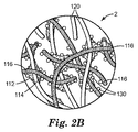
一態様では、本開示は、不織布繊維ウェブの(突起部を有さないと見なされる)主表面から延びる多数の非中空の突起部を画定する、多数の不規則に配向された分離している繊維と、主表面によって画定され、かつこの主表面と実質的に平行な面で、それぞれ隣接する突起部間に形成された多数の実質的に平坦なランド領域と、を含む不織布繊維ウェブを説明する。 In one aspect, the present disclosure is a multiplicity of randomly oriented separations that define a multiplicity of non-hollow projections extending from a major surface (considered as having no projections) of a nonwoven fibrous web. Describe a nonwoven fibrous web comprising fibers and a number of substantially flat land areas formed between adjacent protrusions in a plane that is defined by and is substantially parallel to the major surface. To do.
一部の例示の実施形態では、不規則に配向された分離している繊維は、少なくとも、第1融解温度を有する1つの第1領域と、第2融解温度を有する第2領域とを有する多成分繊維を含み、第1融解温度は第2融解温度よりも低い。配向された分離している繊維の少なくとも一部分は、多成分繊維の第1領域と多数の交点で一緒に結合される。 In some exemplary embodiments, the randomly oriented separated fibers include at least one first region having a first melting temperature and a second region having a second melting temperature. Including component fibers, the first melting temperature is lower than the second melting temperature. At least a portion of the oriented separated fibers are bonded together at a number of intersections with the first region of the multicomponent fiber.
他の代表的な実施形態では、不規則に配向された分離している繊維は、第1融解温度を有する単一成分の分離している熱可塑性繊維の第1の集団と、第1融解温度を超える第2融解温度を有する単一成分の分離している繊維の第2の集団と、を含む。単一成分の分離している繊維の第1の集団の少なくとも一部分は、単一成分の分離している繊維の第2の集団の少なくとも一部分に結合される。 In another exemplary embodiment, the randomly oriented separating fibers comprise a first population of single component separating thermoplastic fibers having a first melting temperature and a first melting temperature. A second population of single component discrete fibers having a second melting temperature greater than. At least a portion of the first population of single component separating fibers is coupled to at least a portion of the second population of single component separating fibers.
これまで説明された実施形態の例示の不織布繊維ウェブでは、ウェブは多数の粒子を更に含んでもよい。粒子の少なくとも一部分は、多成分繊維の少なくとも一部分の少なくとも第1領域又は単一成分の分離している繊維の第1の集団に結合される。いくつかの例示の実施形態では、多数の粒子には、研磨粒子、金属粒子、洗剤粒子、界面活性剤粒子、殺生物剤粒子、吸着剤粒子、吸収剤粒子、マイクロカプセル、及びこれらの組み合わせからなる群から選択される有益粒子が挙げられる。特定の代表的な実施形態では、有益粒子は、活性炭粒子、活性アルミナ粒子、シリカゲル粒子、乾燥剤粒子、アニオン交換樹脂粒子、カチオン交換樹脂粒子、モレキュラーシーブ粒子、珪藻土粒子、抗菌化合物粒子、及びそれらの組み合わせから選択される化学的に活性な粒子を含む。一部の具体的な実施形態では、化学的に活性な粒子は、実質的に不織布繊維ウェブの厚さ全体にわたって分散される。他の具体的な例示の実施形態では、化学的に活性な粒子は、実質的に多数の非中空の突起部の表面上に分散される。 In the exemplary nonwoven fibrous web of the embodiments described so far, the web may further include a number of particles. At least a portion of the particles are bound to at least a first region of at least a portion of the multicomponent fiber or a first population of single component discrete fibers. In some exemplary embodiments, the multiple particles include abrasive particles, metal particles, detergent particles, surfactant particles, biocide particles, adsorbent particles, absorbent particles, microcapsules, and combinations thereof. Beneficial particles selected from the group consisting of: In certain exemplary embodiments, the beneficial particles are activated carbon particles, activated alumina particles, silica gel particles, desiccant particles, anion exchange resin particles, cation exchange resin particles, molecular sieve particles, diatomaceous earth particles, antimicrobial compound particles, and the like A chemically active particle selected from a combination of: In some specific embodiments, the chemically active particles are dispersed substantially throughout the thickness of the nonwoven fibrous web. In another specific exemplary embodiment, the chemically active particles are dispersed on the surface of a substantial number of non-hollow protrusions.
本開示による化学的に活性な粒子を装填した不織布繊維ウェブの例示的実施形態は、様々な用途での使用を可能にする構造的特徴を有し、非常に優れた吸着及び/又は吸収特性を有し、低ソリディティによる高い気孔率及び透過性を示し、及び/又はコスト面で効率的な方法で製造され得る。本開示による化学的に活性な粒子を装填した不織布繊維の特定の例示的実施形態は、小型かつ低コストの流体濾過物品、例えば、家庭用の水フィルタ、又は呼吸器としての使用若しくはHVAC用途のための気体フィルタを提供し得る。 Exemplary embodiments of nonwoven fiber webs loaded with chemically active particles according to the present disclosure have structural features that allow use in a variety of applications and have very good adsorption and / or absorption properties. And exhibit high porosity and permeability with low solidity and / or can be manufactured in a cost effective manner. Certain exemplary embodiments of non-woven fibers loaded with chemically active particles according to the present disclosure are suitable for small and low cost fluid filtration articles such as household water filters, or respiratory use or HVAC applications. A gas filter can be provided.
加えて、いくつかの例示的実施形態では、本開示による化学的に活性な粒子を装填した不織布繊維ウェブは、吸収剤及び/又は吸着剤粒子のような化学的に活性な粒子を高い装填量で有しながら、流体濾過システムを通じた圧力損失を増大させることのない、流体濾過物品の製造を可能にし得る。更に、本開示の化学的に活性な粒子を装填した不織布繊維ウェブのいくつかの例示的実施形態は、より効果的に粒子を繊維不織布繊維ウェブ内に維持しながら、バインダ材料での閉塞によって粒子の化学的に活性な表面積を逆に減少させることがなく、それによって、流体濾過物品として使用されるとき、透過流体中への粒子の放出を防ぐ一方で、化学的に活性な表面積全体と透過流体との相互作用を促進し、向上した耐用年数及び優れた濾過効率をもたらす。 In addition, in some exemplary embodiments, a nonwoven fibrous web loaded with chemically active particles according to the present disclosure is loaded with chemically active particles such as absorbent and / or adsorbent particles. While allowing the production of fluid filtration articles without increasing the pressure loss through the fluid filtration system. Further, some exemplary embodiments of the nonwoven fiber web loaded with chemically active particles of the present disclosure may provide for particles by occlusion with a binder material while more effectively maintaining the particles within the fiber nonwoven fiber web. Does not reduce the chemically active surface area of the surface, thereby preventing the release of particles into the permeate fluid while being used as a fluid filtration article, while the entire chemically active surface area and permeation are prevented. Facilitates interaction with the fluid, resulting in improved service life and excellent filtration efficiency.
更なる態様において、本開示は、前述の実施形態のいずれか1つの不織布繊維ウェブを含む物品を説明し、この物品は、気体濾過物品、液体濾過物品、表面洗浄物品、フロアマット、絶縁物品、細胞成長支持物品、薬物送達物品、個人用衛生物品、及び創傷包帯物品からなる群から選択される。 In a further aspect, the present disclosure describes an article comprising the nonwoven fibrous web of any one of the previous embodiments, the article comprising a gas filtration article, a liquid filtration article, a surface cleaning article, a floor mat, an insulating article, Selected from the group consisting of cell growth support articles, drug delivery articles, personal hygiene articles, and wound dressing articles.
更に他の態様では、本開示は、前述の実施形態のいずれかの不織布繊維ウェブの作製方法を説明し、上端部及び下端部を有する形成チャンバを用意する工程と、多数の繊維を形成チャンバの上端部の中に導入する工程と、繊維の集団を形成チャンバの下端部に実質的に分離している繊維として移送する工程と、特定可能なパターンを有する不織布繊維ウェブとして、実質的に分離している繊維の集団を、パターン付きコレクタ表面上で捕捉する工程と、を含み、特定可能なパターンは、不織布繊維ウェブ(突起部を有さないと見なされる)の主表面から延びる複数の非中空の突起部と、主表面によって画定され、かつ主表面と実質的に平行な面で、それぞれ隣接する突起部間に形成された多数の実質的に平坦なランド領域とを含む。 In yet another aspect, the present disclosure describes a method of making a nonwoven fibrous web according to any of the previous embodiments, comprising providing a forming chamber having an upper end and a lower end, and forming a number of fibers in the forming chamber. Separating substantially as a nonwoven fibrous web having an identifiable pattern, introducing into the upper end, transferring the population of fibers as substantially separated fibers to the lower end of the forming chamber; Capturing a population of fibers on a patterned collector surface, wherein the identifiable pattern comprises a plurality of non-hollows extending from the major surface of the nonwoven fibrous web (considered as having no protrusions) And a plurality of substantially flat land areas each defined between adjacent protrusions in a plane defined by the major surface and substantially parallel to the major surface.
一部の代表的な実施形態では、本方法は、パターン付きコレクタ表面からウェブを取り外す前に、接着剤を使用せずに、多数の繊維の少なくとも一部分を一緒に結合することによって、繊維ウェブを特定可能なパターンに保持させる工程を更に含む。特定の例示の実施形態では、本方法は、実質的に分離している繊維の集団を不織布繊維ウェブとして捕捉する前に、多数の粒子(これは一部の例示の実施形態では、好ましくは化学的に活性な粒子であり得る)を形成チャンバ内に導入し、この形成チャンバ内で多数の分離している繊維を、多数の粒子と混合して、繊維粒子混合物を形成する工程と、粒子の少なくとも一部分を不織布繊維ウェブに固定する工程と、を更に含む。 In some exemplary embodiments, the method includes bonding a fibrous web by bonding at least a portion of a number of fibers together without using an adhesive prior to removing the web from the patterned collector surface. The method further includes a step of holding the pattern in an identifiable pattern. In certain exemplary embodiments, the method may include a number of particles (which, in some exemplary embodiments, preferably chemicals) prior to capturing a substantially separate population of fibers as a nonwoven fibrous web. In the formation chamber and mixing a number of separated fibers with the number of particles to form a fiber particle mixture; Fixing at least a portion to the nonwoven fibrous web.
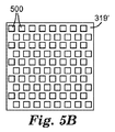
前述の方法のいずれかの更なる例示の実施形態では、パターン付きのコレクタ表面は、コレクタを通じて延びる多数の幾何学的に成形された穿孔を含み、繊維の集団を捕捉する工程は、穿孔されたパターン付きコレクタ表面を通じて真空に引くことを含む。特定の代表的な実施形態では、多数の幾何学的に成形された穿孔は、円、楕円、多角形、X型、V型、螺旋、及びこれらの組み合わせからなる群から選択される形を有する。一部の特定の代表的な実施形態では、多数の幾何学的に成形された穿孔は、三角形、正方形、矩形、ダイヤモンド、台形、五角形、六角形、八角形、及びこれらの組み合わせからなる群から選択される、多角形の形状を有する。特定の代表的な実施形態では、多数の幾何学的に成形された穿孔は、パターン付きコレクタ表面における二次元パターンを含む。他の代表的な実施形態では、パターン付きコレクタ表面における幾何学的に成形された穿孔の二次元パターンは、二次元アレイである。 In a further exemplary embodiment of any of the foregoing methods, the patterned collector surface includes a number of geometrically shaped perforations extending through the collector, and the step of capturing the population of fibers is perforated. Including drawing a vacuum through the patterned collector surface. In certain exemplary embodiments, the multiple geometrically shaped perforations have a shape selected from the group consisting of a circle, an ellipse, a polygon, an X shape, a V shape, a helix, and combinations thereof. . In some particular exemplary embodiments, the multiple geometrically shaped perforations are from the group consisting of triangles, squares, rectangles, diamonds, trapezoids, pentagons, hexagons, octagons, and combinations thereof. It has a polygonal shape that is selected. In certain exemplary embodiments, the multiple geometrically shaped perforations include a two-dimensional pattern on the patterned collector surface. In another exemplary embodiment, the two-dimensional pattern of geometrically shaped perforations on the patterned collector surface is a two-dimensional array.
本開示の例示的な実施形態の種々の態様及び利点の概要がまとめられてきた。上記の概要は、本発明の図解された各実施形態、又は本発明のあらゆる実施を記載するものではない。図及び以下の詳細な説明は、本明細書に開示された原理を使用する特定の好ましい実施形態を更に具体的に例示する。 A summary of various aspects and advantages of exemplary embodiments of the present disclosure has been compiled. The above summary is not intended to describe each illustrated embodiment or every implementation of the present invention. The drawings and the following detailed description more particularly exemplify certain preferred embodiments using the principles disclosed herein.
本開示の例示的実施形態を添付の図面を参照して更に説明する。
原寸大で描写されない場合がある、上で特定された図面は、本開示の様々な実施形態を説明するが、詳細な説明で言及されるように、他の実施形態も検討される。いかなる場合でも、本開示は、制限を表すことではなく、例示的実施形態の表示によって、ここに開示される発明を説明する。本発明の範囲及び趣旨の中で、多くの他の修正及び実施形態が、当業者によって考案され得ることを理解されたい。 Although the drawings identified above, which may not be drawn to scale, describe various embodiments of the present disclosure, other embodiments are also contemplated, as noted in the detailed description. In no event is this disclosure intended to describe the invention disclosed herein by way of representation of exemplary embodiments, rather than representing limitations. It should be understood that many other modifications and embodiments can be devised by those skilled in the art within the scope and spirit of the invention.
本明細書及び添付の実施形態において使用されるとき、単数形「a」、「an」及び「the」は、その内容について別段の明確な指示がない限り、複数の指示対象を包含する。したがって、例えば「化合物(a compound)」を含有する微細繊維への言及は、2種以上の化合物の混合物を含む。本明細書及び添付の実施形態において使用されるとき、用語「又は」は、その内容が特に明確に指示しない限り、一般的に「及び/又は」を包含する意味で用いられる。 As used herein and in the appended embodiments, the singular forms “a”, “an”, and “the” include plural referents unless the content clearly dictates otherwise. Thus, for example, reference to a fine fiber containing "a compound" includes a mixture of two or more compounds. As used herein and in the appended embodiments, the term “or” is generally employed in its sense including “and / or” unless the content clearly dictates otherwise.
本明細書で使用するとき、末端値による数値範囲での記述には、その範囲内に包含されるあらゆる数値が含まれる(例えば、1〜5は、1、1.5、2、2.75、3、3.8、4、及び5を含む)。
As used herein, the recitation of numerical ranges by terminal values includes any numerical value subsumed within that range (
特に指示がない限り、明細書及び実施形態に使用されている成分の量、性質の測定値などを表す全ての数は、全ての例において、用語「約」により修飾されていることを理解されたい。したがって、特に指示がない限り、先行の本明細書及び添付の実施形態の列挙に記載の数値的パラメータは、本開示の教示を利用して当業者により得ることが求められる所望の性質に応じて変化し得る近似値である。最低限でも、また、請求される実施形態の範囲への同等物の原則の適用を限定する試行としてではなく、少なくとも各数値パラメータは、報告された有効数字の数を考慮して、そして通常の概算方法を適用することによって解釈されなければならない。 Unless otherwise indicated, it is understood that all numbers representing amounts of ingredients, properties measurements, etc. used in the specification and embodiments are modified by the term “about” in all examples. I want. Thus, unless otherwise indicated, the numerical parameters set forth in the preceding specification and the enumeration of the appended embodiments are dependent on the desired properties sought to be obtained by those skilled in the art using the teachings of the present disclosure. Approximate value that can change. At a minimum, and not as an attempt to limit the application of the principle of equivalents to the scope of the claimed embodiments, at least each numerical parameter takes into account the number of significant figures reported and is It must be interpreted by applying an estimation method.
以下の用語集の定義された用語について、請求項又は明細書の他の箇所で異なる定義が提供されない限り、これらの定義が出願全体に適用されるものとする。 For the defined terms in the following glossary, these definitions shall apply throughout the application unless a different definition is provided in the claims or elsewhere in the specification.
用語
「不織布繊維ウェブ」とは、交互に置かれるが、編布におけるような特定可能な様式ではない、個々の繊維又は繊維の構造を有する物品又はシートを指す。不織布又はウェブは、例えば、メルトブロー法、エアレイ加工及び結合カードウェブ法の多くの方法から形成されている。
The term “nonwoven fibrous web” refers to an article or sheet having individual fibers or fiber structures that are interleaved but not in an identifiable manner as in a knitted fabric. Nonwoven fabrics or webs are formed from many methods, for example, meltblowing, air laying and bonded card web methods.
「凝集不織布繊維ウェブ」とは、自己支持性があるウェブを形成するのに十分な繊維の交絡又は結合を特徴とする、繊維ウェブを意味する。 By “agglomerated nonwoven fibrous web” is meant a fibrous web characterized by sufficient fiber entanglement or bonding to form a self-supporting web.
「自己支持性がある」とは、実質的に破けたり破損することがなく、覆いやすく、かつ取り扱いやすい、十分な粘調度及び強度を有するウェブを意味する。 “Self-supporting” means a web having sufficient consistency and strength that is substantially easy to cover and handle without substantial tearing or breakage.
「ダイ」とは、ポリマー溶融加工及び繊維押し出し加工において使用される加工用アセンブリを意味し、それらの工程にはメルトブロー及びスパンボンドが挙げられるが、これらに限定されない。 "Die" means a processing assembly used in polymer melt processing and fiber extrusion processing, including, but not limited to, meltblowing and spunbonding.
「メルトブロー」及び「メルトブローン法」とは、複数のオリフィスを通じて溶融繊維形成材料を押出し、繊維を形成しながら、この繊維を空気又は他の減衰流体と接触させて、繊維を繊維の中に減衰させた後、減衰させた繊維を収集することによって、不織布繊維ウェブを形成するための方法を意味する。例示的メルトブロー法は、例えば、米国特許第6,607,624号(Berriganら)において教示される。 “Meltblowing” and “meltblown process” refers to extruding molten fiber-forming material through a plurality of orifices and forming the fiber while contacting the fiber with air or other damping fluid to damp the fiber into the fiber. After that, it means a method for forming a nonwoven fibrous web by collecting the damped fibers. An exemplary meltblowing process is taught, for example, in US Pat. No. 6,607,624 (Berrigan et al.).
「メルトブローン繊維」とは、メルトブロー又はメルトブローン法によって作製された繊維を意味する。 The “melt blown fiber” means a fiber produced by a melt blow or melt blown method.
「スパンボンディング」及び「スパンボンド法」とは、紡糸口金の複数の微細な毛管から、連続又は半連続繊維として溶融繊維形成材料を押出した後、減衰繊維を収集することによって、不織布繊維ウェブを形成するための方法を意味する。代表的なスパンボンド法は、例えば米国特許第3,802,817号(Matsukiら)に開示されている。 “Spunbonding” and “spunbonding” refers to the process of extruding molten fiber-forming material as continuous or semi-continuous fibers from a plurality of fine capillaries of a spinneret, and then collecting the damped fibers to collect the nonwoven fiber web. Means a method for forming. A typical spunbond process is disclosed, for example, in US Pat. No. 3,802,817 (Matsuki et al.).
「スパンボンド繊維」及び「スパンボンドされた繊維」は、スパンボンディング又はスパンボンド法を使用して作製された繊維を意味する。そのような繊維は、一般に、連続繊維であり、凝集不織布繊維ウェブを形成するように十分に交絡又は点接合されるため、通常、そのような繊維の塊から1つの完全なスパンボンド繊維を除去することは不可能である。またこの繊維は、例えば、非従来形状を有する繊維について説明している、米国特許第5,277,976号(Hogleら)に記載されるものなどの形状を有してもよい。 “Spunbond fibers” and “spunbonded fibers” refer to fibers made using a spunbonding or spunbonding process. Such fibers are generally continuous fibers and are sufficiently entangled or point bonded to form an agglomerated nonwoven fiber web, so typically one complete spunbond fiber is removed from such a fiber mass. It is impossible to do. The fibers may also have shapes such as those described in US Pat. No. 5,277,976 (Hogle et al.), Which describes fibers having non-conventional shapes, for example.
「カーディング」及び「カード法」とは、コーミング又はカーディングユニットを通じてステープルファイバーを加工することによって、不織布繊維ウェブを形成する方法であって、ステープルファイバーを分離又は分解し、機械方向に整列させて、一般に機械方向に配向された繊維不織布ウェブを形成する方法を意味する。例示的カード法は、例えば、米国特許第5,114,787号(Chaplinら)において教示される。 “Carding” and “carding” are methods for forming a nonwoven fibrous web by processing staple fibers through a combing or carding unit, where the staple fibers are separated or disassembled and aligned in the machine direction. In general, it means a method of forming a fibrous nonwoven web oriented in the machine direction. An exemplary card method is taught, for example, in US Pat. No. 5,114,787 (Chaplin et al.).
「結合カードウェブ」とは、カード法によって形成された不織布繊維ウェブを指し、繊維の少なくとも一部分が、例えば、熱点接合、自己結合、熱風結合、超音波結合、ニードルパンチング、カレンダ加工、スプレー接着の適用などを含む方法によって一緒に結合される。 “Bonded card web” refers to a nonwoven fibrous web formed by the card method, where at least a portion of the fibers are, for example, hot spot bonded, self bonded, hot air bonded, ultrasonic bonded, needle punched, calendered, spray bonded Are combined together by methods including application of
「自己結合」とは、点接合又はカレンダ加工のように固体接触圧力を印加することがなくとも、オーブン内又はスルーエア結合機で得られるような高温での繊維間の結合を意味する。 “Self-bonding” means bonding between fibers at high temperatures, such as obtained in an oven or through-air bonder, without applying solid contact pressure as in point bonding or calendering.
「カレンダ加工」とは、不織布繊維ウェブを加圧しながらローラーに通して、圧縮及び結合された繊維不織布ウェブを得る工程を意味する。ローラーは任意追加的に、加熱されてもよい。 “Calendaring” means the process of passing a nonwoven fibrous web through a roller while pressing to obtain a compressed and bonded fibrous nonwoven web. The roller may optionally be heated.
「高密度化」とは、フィルタ巻き取り軸又はマンドレルの上に直接又は間接的に堆積した繊維を、堆積前又は堆積後に圧縮し、そして意図的であれ、形成中のフィルタ又は形成されたフィルタを取り扱ういくつかの工程の人為的結果としてであれ、より多孔性の低い領域を全般的に又は局所的に形成するように製造する工程を意味する。高密度化はまた、ウェブのカレンダ加工法を含む。 “Densification” refers to compressing a fiber deposited directly or indirectly on a filter take-up shaft or mandrel before or after deposition and, if intended, a forming filter or formed filter Mean the process of producing a less porous region, either globally or locally, as an artifact of several processes dealing with the process. Densification also includes web calendering methods.
「空隙体積」とは、ウェブ又はフィルタのような多孔質若しくは繊維状の本体内における無充填スペースの百分率又は少数値を意味し、ウェブ又はフィルタの重量及び体積を測定した後に、このフィルタの重量と、体積の等しい同一の構成材料からなる固体塊の理論上の重量とを比較することにより算出することができる。 "Void volume" means the percentage or fractional value of unfilled space in a porous or fibrous body such as a web or filter, and after measuring the weight and volume of the web or filter, the weight of this filter And the theoretical weight of a solid mass made of the same constituent material having the same volume can be calculated.
「多孔性」とは、材料中の空隙スペースの1つの尺度を意味する。孔及び空隙の寸法、頻度、数、及び/又は相互接続性が、材料の多孔性に影響する。 “Porosity” means one measure of void space in a material. The size, frequency, number, and / or interconnectivity of the pores and voids affect the porosity of the material.
不織布繊維ウェブの主表面から延在する突起部に特に言及した「非中空の」は、突起部が、不規則に配向された分離している繊維間の顕微鏡的なボイド(すなわち、ボイド容積)以外の内部キャビティ又はボイド領域を含有しないということを意味する。 “Non-hollow” with particular reference to protrusions extending from the main surface of the nonwoven fibrous web is a microscopic void between separated fibers in which the protrusions are randomly oriented (ie, void volume). Means that it contains no internal cavities or void areas.
繊維の集団に特に言及した「不規則に配向された」は、繊維体が実質的に単一の方向に配列していないということを意味する。 “Randomly oriented” specifically referring to a population of fibers means that the fiber bodies are not substantially arranged in a single direction.
「エアレイ加工」は、不織布繊維ウェブ層を形成することができる工程である。エアレイ法では、約3〜約52ミリメートル(mm)の典型的な長さを有する小繊維の束が分離されて給気に混入された後、通常、真空供給の助けで形成スクリーンの上に蒸着される。次に、不規則に配向された繊維は、例えば、熱点接合、自己結合、熱風結合、ニードルパンチング、カレンダ加工、スプレー接着などを使用して、互いに結合されてもよい。例示的エアレイ法は、例えば、米国特許第4,640,810号(Laursenら)において教示される。 “Airlaid processing” is a process by which a nonwoven fibrous web layer can be formed. In the air lay method, bundles of fibrils having typical lengths of about 3 to about 52 millimeters (mm) are separated and mixed into the supply air and then typically deposited on the forming screen with the aid of a vacuum supply. Is done. The randomly oriented fibers may then be bonded together using, for example, hot spot bonding, self bonding, hot air bonding, needle punching, calendering, spray bonding, and the like. Exemplary airlaid methods are taught, for example, in US Pat. No. 4,640,810 (Laursen et al.).
「ウェットレイ法」は、不織布繊維ウェブ層を形成することができる工程である。ウェットレイ法では、約3〜約52ミリメートル(mm)の範囲の典型的な長さを有する小繊維の束が分離されて液体供給に混入された後、通常、真空供給の助けで形成スクリーンの上に蒸着される。水は、一般的に好ましい液体である。ランダムに蒸着された繊維は、更に交絡(例えば、水流交絡)され得るか、又は例えば、熱点接合、自己結合、熱風結合、超音波結合、ニードルパンチング、カレンダ加工、スプレー接着の適用などを使用して、互いに結合されてもよい。代表的なウェットレイ及び結合プロセスは、例えば、米国特許第5,167,765号(Nielsenら)において教示される。代表的な結合プロセスはまた、例えば米国特許出願公開第2008/0038976(A1)号に開示されている。 The “wet lay method” is a process that can form a nonwoven fibrous web layer. In the wet lay process, bundles of fibrils having typical lengths in the range of about 3 to about 52 millimeters (mm) are separated and mixed into the liquid supply, and then usually with the help of a vacuum supply of the forming screen. Deposited on top. Water is a generally preferred liquid. Randomly deposited fibers can be further entangled (eg hydroentangled) or using, for example, hot spot bonding, self-bonding, hot air bonding, ultrasonic bonding, needle punching, calendering, spray bonding applications, etc. And may be combined with each other. An exemplary wet lay and bonding process is taught, for example, in US Pat. No. 5,167,765 (Nielsen et al.). An exemplary bonding process is also disclosed, for example, in US Patent Application Publication No. 2008/0038976 (A1).
「共形成すること」又は「共形成法」とは、少なくとも1つの繊維層が、少なくとも1つの異なる繊維層の形成と実質的に同時又は即時形成される工程を意味する。共形成法によって生成されたウェブは、一般に、「共形成ウェブ」と称される。 “Co-forming” or “co-forming method” means a process in which at least one fiber layer is formed substantially simultaneously or immediately with the formation of at least one different fiber layer. Webs produced by the co-forming method are commonly referred to as “co-formed webs”.
「粒子装填」又は「粒子装填法」とは、形成している間に粒子が繊維流又はウェブに添加される工程を意味する。例示的な粒子装填法は、例えば、米国特許第4,818,464号(Lau)及び同第4,100,324号(Andersonら)において教示される。 “Particle loading” or “particle loading method” means the process in which particles are added to a fiber stream or web during formation. Exemplary particle loading methods are taught, for example, in US Pat. Nos. 4,818,464 (Lau) and 4,100,324 (Anderson et al.).
「粒子」及び「粒子」は、実質上互換的に使用される。概して、粒子又は粒子とは、超粒子形状の材料の分離している小片又は個々の部分を意味する。しかし、粒子は、微粉砕形態の個別粒子が共に関連又は集積した総体を含んでもよい。したがって、本開示の特定の例示的実施形態で使用される単独粒子は、凝集、物理的噛み合い、静電結合、又は他の結び付き方により粒子を形成してもよい。特定の例において、個別粒子の凝集体の形態を取る粒子は、米国特許第5,332,426号(Tangら)に記載されるように意図的に形成することもできる。 “Particle” and “particle” are used substantially interchangeably. In general, a particle or particle means a discrete piece or individual portion of a superparticulate material. However, the particles may comprise a total of associated or agglomerated individual particles in finely divided form. Thus, single particles used in certain exemplary embodiments of the present disclosure may form particles by agglomeration, physical engagement, electrostatic coupling, or other association methods. In certain instances, particles that take the form of agglomerates of individual particles can also be intentionally formed as described in US Pat. No. 5,332,426 (Tang et al.).
「粒子装填媒体」又は「粒子を装填した不織布繊維ウェブ」とは、繊維内に捕捉されるか、又は繊維に結合された粒子、化学的に活性な粒子を含有する、分離している繊維の開放構造の交絡塊を有する、不織布ウェブを意味する。 "Particle loading medium" or "non-woven fibrous web loaded with particles" refers to the separated fibers containing particles, chemically active particles that are trapped within or bound to the fibers. By non-woven web having an entangled mass of open structure.
「捕捉される」とは、粒子がウェブの繊維中に分散されて物理的に保持されていることを意味する。一般に、繊維及び粒子に沿って点接触及び線接触しているため、粒子のほぼ全ての表面積が流体との相互作用に利用できる。 By “trapped” is meant that the particles are dispersed and physically held in the fibers of the web. In general, due to point and line contact along the fibers and particles, almost all of the surface area of the particles is available for interaction with the fluid.
「マイクロ繊維」とは、集団メジアン径が少なくとも1マイクロメートル(μm)である繊維の集団である。 A “microfiber” is a population of fibers having a population median diameter of at least 1 micrometer (μm).
「粗大マイクロファイバー」とは、集団メジアン径が少なくとも10μmであるマイクロファイバーの集団を意味する。 “Coarse microfiber” means a population of microfibers having a population median diameter of at least 10 μm.
「微細マイクロファイバー」とは、集団メジアン径が10μm未満のマイクロファイバーの集団を意味する。 “Fine microfiber” means a population of microfibers having a population median diameter of less than 10 μm.
「超微細マイクロファイバー」とは、メジアン繊維径が2μm以下であるマイクロファイバーの集団を意味する。 “Ultrafine microfiber” means a group of microfibers having a median fiber diameter of 2 μm or less.
「サブマイクロメートル繊維」とは、集団メジアン径が1μm未満である繊維の集団を意味する。 “Sub-micrometer fiber” means a population of fibers having a population median diameter of less than 1 μm.
「連続的な配向されたマイクロ繊維」とは、ダイから出て、処理ステーションを通り、そこで繊維が恒久的に引き延ばされ、繊維内のポリマー分子の少なくとも一部が繊維の長手方向軸に対して整列するように恒久的に配向される本質的に連続な繊維を意味する(特定の繊維に関して使用される「配向された」とは、繊維のポリマー分子の少なくとも一部分が、繊維の長手方向軸に沿って整列していることを意味する)。 “Continuously oriented microfibers” refers to exiting a die and passing through a processing station where the fibers are permanently stretched so that at least some of the polymer molecules in the fibers are in the longitudinal axis of the fibers. Means essentially continuous fibers that are permanently oriented to align with each other ("oriented" as used with respect to a particular fiber means that at least a portion of the polymer molecules of the fiber Means aligned along the axis).
「別々に作製されたマイクロファイバー」とは、マイクロファイバー流が最初はより大きい寸法のマイクロファイバー流から空間的に分離している(例えば、約1インチ(25mm)以上の距離をあけて)が、そのマイクロファイバー流に飛翔中に合流して分散するように位置決めされたマイクロファイバー形成装置(例、ダイ)から製造されるマイクロファイバーの流れを意味する。 “Separately produced microfibers” means that the microfiber stream is initially spatially separated from the larger dimension microfiber stream (eg, at a distance of about 1 inch (25 mm) or more). , Means a microfiber flow produced from a microfiber forming device (eg, die) positioned to join and disperse the microfiber flow during flight.
「ウェブ坪量」は、10cm×10cmウェブサンプルの重量から算出され、通常、平方メートル当たりのグラム(gsm)で表される。 “Web basis weight” is calculated from the weight of a 10 cm × 10 cm web sample and is usually expressed in grams per square meter (gsm).
「ウェブ厚さ」は、10cm×10cmのウェブサンプルから、5cm×12.5cm寸法のテスター脚部を有する厚さテストゲージを用い、150Paの圧力を加えて測定される。 “Web thickness” is measured from a 10 cm × 10 cm web sample using a thickness test gauge having tester legs measuring 5 cm × 12.5 cm and applying a pressure of 150 Pa.
「嵩密度」とは、文献からの引用で、ウェブを組成する嵩ポリマー又はポリマーブレンドの単位容積当たりの質量である。 “Bulk density” is a quote from the literature and is the mass per unit volume of the bulk polymer or polymer blend that makes up the web.
「有効繊維直径」又は「EFD」とは、室温で1気圧(0.1MPa)の空気を特定の厚さ及び前面速度(通常、5.3cm/秒)でウェブサンプルに通過させて、対応する圧力損失を計測する空気透過試験に基づく、繊維ウェブの繊維の視直径である。計測された圧力損失を基に、Davies,C.N.の「The Separation of Airborne Dust and Particulates」(Institution of Mechanical Engineers,London Proceedings,1B(1952))に記載のとおり有効繊維直径が算出される。 “Effective fiber diameter” or “EFD” corresponds to passing 1 atm (0.1 MPa) of air at room temperature at a specified thickness and front speed (usually 5.3 cm / sec) through the web sample. It is the fiber diameter of the fiber web based on an air permeation test that measures pressure loss. Based on the measured pressure loss, Davies, C .; N. The effective fiber diameter is calculated as described in “The Separation of Arborne Dust and Particulates” (Institution of Mechanical Engineers, London Proceedings, 1B (1952)).
「分子的に同一のポリマー」とは、本質的に同じ繰り返し分子単位を有するが、分子量、製造方法、市販形態等が異なる場合があるポリマーを意味する。 “Molecularly identical polymer” means a polymer that has essentially the same repeating molecular units but may differ in molecular weight, production method, commercial form, and the like.
「層」とは、2つの主表面間に形成される単一の層を意味する。1つの層が、単一のウェブ、例えば、ウェブの厚みを画定する第1及び第2主表面を有する単一ウェブ内に多数の層と共に形成される単一の層内に内部的に存在する場合がある。層はまた、例えば、ウェブの厚みを画定する第1及び第2主表面を有する第1ウェブに単一の階層があり、そのウェブが、第2ウェブの厚みを画定する第1及び第2主表面を有する第2ウェブにより上又は下から重ねられ、この場合、第1及び第2ウェブのそれぞれが少なくとも1つの層を形成するように、多数のウェブを含む複合物品で存在する場合もある。加えて、単一のウェブ内、及び、それぞれが1つの層を形成するそのウェブと1つ以上の他のウェブとの間に、複数の層が同時に存在し得る。 “Layer” means a single layer formed between two major surfaces. One layer resides internally in a single web, eg, a single layer formed with multiple layers in a single web having first and second major surfaces that define the thickness of the web. There is a case. The layer may also be a first layer having, for example, a first web having first and second major surfaces defining a thickness of the web, the first and second major layers defining a thickness of the second web. It may be overlaid from above or below by a second web having a surface, in which case it may be present in a composite article comprising a number of webs such that each of the first and second webs forms at least one layer. In addition, there can be multiple layers simultaneously within a single web and between that web and one or more other webs, each forming a layer.
特定の第1層に関して「隣接する」とは、第1層及び第2層がそれぞれ隣り合って(すなわち、隣接して)、互いに直接接触するか、又は互いに接在するが、直接接触しない(すなわち、第1層と第2層との間に介在する、1つ以上の追加的な層がある)位置で、別の第2の層に接合又は結合されていることを意味する。 “Adjacent” with respect to a particular first layer means that the first layer and the second layer are adjacent to each other (ie, adjacent to each other), or are in direct contact with each other, but are not in direct contact ( That is, it is joined or bonded to another second layer at a position where there is one or more additional layers interposed between the first layer and the second layer.
「粒子密度勾配」、「吸着剤密度勾配」、及び「繊維集団密度勾配」とは、特定の繊維集団内での粒子、収着剤、又は繊維材料の含量(例えば、ウェブの指定領域上の単位体積当たりの所定の材料の数、重量、又は体積)が、不織布繊維ウェブ全体にわたって均一である必要はなく、ウェブの特定領域にはより多く、他の領域にはより少なく材料を提供するように変動し得ることを意味する。 “Particle density gradient”, “adsorbent density gradient”, and “fiber population density gradient” are the contents of particles, sorbents, or fiber materials within a particular fiber population (eg, on a specified area of the web). (The number, weight, or volume of a given material per unit volume) need not be uniform throughout the nonwoven fibrous web, so that it provides more material in certain areas of the web and less material in other areas. It means that it can fluctuate.
「流体処理ユニット」、「流体濾過物品」、又は「流体濾過システム」とは、多孔質不織布繊維ウェブのような流体濾過媒体を含む物品を意味する。これらの物品は一般的に、流体濾過媒体のためのフィルタハウジング、及び処理された流体をこのフィルタハウジングから適切な方法で排出するための出口を含む。「流体濾過システム」という用語はまた、未処理の気体又は液体のような、未加工の流体を、処理済の流体から分離するいずれの関連方法をも含む。 By “fluid treatment unit”, “fluid filtration article” or “fluid filtration system” is meant an article comprising a fluid filtration medium, such as a porous nonwoven fibrous web. These articles generally include a filter housing for the fluid filtration media and an outlet for expelling the treated fluid from the filter housing in an appropriate manner. The term “fluid filtration system” also includes any related method of separating raw fluid, such as raw gas or liquid, from processed fluid.
本開示の様々な例示的実施形態について、ここで特に図面を参照して説明する。本発明の例示的な実施形態は、本開示の趣旨及び範囲から逸脱することなく、様々な修正形態及び変更形態を取ることができる。それ故に、本発明の実施形態は次に記載される実施形態に限定されるべきではなく、請求項及びそのいずれかの等価物に記載される限定によって制御されるべきであることは理解される必要がある。 Various exemplary embodiments of the present disclosure will now be described with particular reference to the drawings. The exemplary embodiments of the present invention may take various modifications and changes without departing from the spirit and scope of the present disclosure. Therefore, it is understood that embodiments of the invention should not be limited to the embodiments described below, but should be controlled by the limitations set forth in the claims and any equivalents thereof. There is a need.
A.パターン付きエアレイド不織布繊維ウェブ
本開示は、一部の代表的な実施形態では、パターン付きコレクタ表面によって決定された特定可能なパターン内に捕捉され、パターン付きコレクタ表面から取り外す前に、接着剤を使用せずに一緒に結合される、エアレイ加工された分離している繊維の集団を含む、パターン付きエアレイド不織布繊維ウェブを説明する。二次元若しくは三次元の構造化表面を有するパターン付きエアレイド不織布繊維ウェブは、パターン付きコレクタ表面上においてエアレイ加工された分離している繊維を捕捉し、コレクタ上にある間に、例えば、コレクタ上で空気通過ボンダーの下で繊維を熱結合することにより、接着剤を使用せずに繊維を結合することによって形成されてもよい。
A. The present disclosure provides, in some exemplary embodiments, an adhesive that is captured within an identifiable pattern determined by the patterned collector surface and removed from the patterned collector surface before being removed. A patterned airlaid nonwoven fibrous web is described that includes a population of airlaid separated fibers that are bonded together without. A patterned air-laid nonwoven fibrous web having a two-dimensional or three-dimensional structured surface captures the separated fibers that are air-laid on the patterned collector surface, while on the collector, for example, on the collector It may be formed by bonding the fibers without using an adhesive by thermally bonding the fibers under an air passing bonder.
実質的に平坦な、又は非平滑化されていない表面を有する非パターン付きエアレイドウェブは、例えば、米国特許第7,491,354号及び同第6,808,664号(Andersenら)に記載されるように既知であるが、従来のエアレイドウェブは概して、コレクタ表面から取り外された後に、かつカレンダ操作を通過するまで、構造的に安定なウェブに結合されないため、従来のエアレイドウェブは、パターン付き効果を達成することができないか、又はコレクタの表面上に形成された任意の特定可能なパターンを保持することができない。 Non-patterned airlaid webs having a substantially flat or non-smoothed surface are described, for example, in US Pat. Nos. 7,491,354 and 6,808,664 (Andersen et al.). Although conventional airlaid webs are generally not patterned, they are not bonded to a structurally stable web after being removed from the collector surface and until passing through a calendering operation. The effect cannot be achieved or any identifiable pattern formed on the surface of the collector cannot be retained.
図1は、本開示に従って、複数の不規則に配向された分離している繊維2を含む、パターン付きエアレイド不織布繊維ウェブ234の1つの代表的な実施形態の斜視図である。一部の代表的な実施形態では、本開示は、不織布繊維ウェブの(突起部を有さないと見なされる)主表面から延びる複数の非中空の突起部200を画定する、複数の不規則に配向された分離している繊維2と、主表面204によって画定され、かつこの主表面204と実質的に平行な面で、それぞれ隣接する突起部200間に形成された複数の実質的に平坦なランド領域202と、を含む不織布繊維ウェブを説明する。図1は、パターン付きエアレイド不織布繊維ウェブ234の主表面204に実質的に平行な方向で規則的なアレイで配列した複数のダイヤモンドの形をした断面の幾何学的な形状を有する突起部200を図示しているが、本開示が、この幾何学的な形状又は幾何学的な形状の規則的なアレイに限定されないということが理解される。更に以下に説明されるように、他の幾何学的形状(例えば、円形、楕円形、多角形、x型、v型、十字等)は、複数の突起部200の規則的なアレイパターン及び不規則な配置の両方共に、本開示の範囲内である。
FIG. 1 is a perspective view of one exemplary embodiment of a patterned airlaid nonwoven
不規則に配向された分離している繊維2は、いくつかの実施形態では任意追加的に充填繊維を含んでもよい。充填繊維は、多成分繊維以外の任意の繊維である。任意追加の充填繊維は、好ましくは単一成分繊維であり、熱可塑性又は「溶けかかった」繊維であってもよい。任意追加の充填繊維は、一部の代表的な実施形態では、以下で更に説明される天然繊維、より好ましくは再生可能な源に由来する天然繊維、及び/又は統合再利用材料を含む。
The randomly oriented separating
前述のパターンを付きエアレイド不織布繊維ウェブの一部の代表的な実施形態では、パターン付きエアレイド不織布繊維ウェブ234は、任意追加的に図2A及び2Bに示すように複数の粒子130を含んでもよい。図2A及び2Bは、図1のパターン付きエアレイド不織布繊維ウェブ234の領域2Aの分解図を示し、不規則に配向された分離している繊維2、及び複数の任意追加の粒子130を含んでいるのが示されている。
In some exemplary embodiments of the patterned airlaid nonwoven fibrous web described above, the patterned airlaid nonwoven
したがって、図2Aに示される代表的な実施形態では、パターン付きエアレイド不織布繊維ウェブ234は、複数の不規則に配向された分離している繊維2と、任意追加的に複数の粒子130(これは化学的に活性な粒子であってもよい)とを含み、この不規則に配向された分離している繊維は、少なくとも、第1融解温度を有する第1領域112と第2融解温度を有する第2領域114と含む多成分繊維110を含み、第1融解温度は第2融解温度未満よりも低い。
Thus, in the exemplary embodiment shown in FIG. 2A, the patterned airlaid nonwoven
一部の現状における好ましい代表的な実施形態では、多成分繊維110は、不織布繊維ウェブの総重量の少なくとも10重量%の量で繊維ウェブ内に構成される。他の代表的な実施形態では、多成分繊維110は、不織布繊維ウェブの総重量の0重量%超〜10重量%(% wt.)未満を構成する。かかる実施形態は、以下に更に説明されるように、粒子を装填したパターン付きエアレイド不織布繊維ウェブとの使用に現状において好ましい。更なる例示的実施形態では、多成分繊維110は、分離している繊維の総重量の0重量%超〜10重量%未満を構成する。このような実施形態は、下記に更に記述するように化学的に活性な粒子を装填したパターン付きエアレイド不織布繊維ウェブと共の使用に本発明で好ましい。
In some presently preferred exemplary embodiments, the
多成分繊維110を使用することによって、追加の接着剤又はバインダコーティングを必要とせずに、分離している繊維2を粒子130と一緒に固定することが可能になる。特定の現状において好ましい実施形態では、化学的に活性な粒子130の少なくとも一部分は、多成分繊維110の少なくとも一部分の少なくとも第1領域112に結合され、分離している繊維2の少なくとも一部分は、複数の交点において、多成分繊維110の第1領域112と一緒に結合される。
The use of
任意追加的に、不織布物品は、充填繊維120、つまり多成分繊維ではなく、好ましくは単一成分繊維及び/又は天然繊維である、不規則に配向された分離している繊維2を含む。いくつかの現状における好適な実施形態では、少なくとも充填繊維120の一部が、多成分繊維110の第1領域112と共に、複数の交点において、分離している繊維2の少なくとも一部分に結合されてもよい。
Optionally, the nonwoven article comprises randomly oriented separated
図2Bに示される図1の分解図によって示される別の例示的な実施形態では、パターン付きエアレイド不織布繊維ウェブ234は、複数の不規則に配向された分離している繊維2と、任意追加的に、複数の粒子130(これは化学的に活性な粒子であり得る)と、を含み、この不規則に配向された分離している繊維2は、少なくとも第1融解温度を有する単一成分の分離している熱可塑性繊維116の第1の集団と、第1融解温度を超える第2融解温度を有する単一成分の分離している繊維120の第2の集団と、を含む。粒子130の少なくとも一部分は、単一成分の分離している繊維116の第1の集団の少なくとも一部分に結合され、単一成分の分離している繊維116の第1の集団の少なくとも一部分は、単一成分の分離している繊維120の第2の集団の少なくとも一部分に結合される。
In another exemplary embodiment illustrated by the exploded view of FIG. 1 shown in FIG. 2B, the patterned airlaid nonwoven
充填繊維を含む、パターン付きエアレイド不織布繊維ウェブ234のいくつかの代表的な実施形態では、粒子は、充填繊維に実質的に結合されないことが好ましく、特定の例示の実施形態では、充填繊維は互いに実質的に結合されない。
In some exemplary embodiments of the patterned airlaid nonwoven
一部の現状において好ましい代表的な実施形態では、多成分繊維110は、不織布繊維ウェブの総重量の少なくとも10重量%、20重量%、30重量%、40重量%、50重量%、又は更には60重量%の量で、並びに好ましくは不織布繊維ウェブの総重量の100重量%以下、90重量%以下、80重量%以下、70重量%以下、又は更には60重量%以下の量で繊維ウェブ内で構成される。
In some presently preferred exemplary embodiments, the
他の本発明で好ましい代表的な実施形態では、単一成分の分離している繊維116の第1の集団は、不織布繊維ウェブの総重量の0重量%超〜10重量%未満、より好ましくは、1〜10重量%、2〜9重量%、3〜8重量%を構成する。特定の例示の実施形態では、単一成分の分離している繊維116の第1の集団は、複数の不規則に配向された分離している繊維の0重量%超〜10重量%未満、より好ましくは1重量%〜10重量%、2重量%〜9重量%、3重量%〜8重量%を構成する。
In other exemplary embodiments preferred in the present invention, the first population of single component
特定の例示的実施形態では、単一成分の分離している繊維116の第1の集団は、ポリエステル、ポリアミド、ポリオレフィン、環状ポリオレフィン、ポリオレフィン系熱可塑性エラストマー、ポリ(メタ)アクリレート、ポリハロゲン化ビニル、ポリアクリロニトリル、ポリウレタン、ポリ乳酸、ポリビニルアルコール、ポリフェニレンスルフィド、ポリスルフォン、ポリオキシメチレン、流体結晶ポリマー、及びそれらの組み合わせからなる群から選択されるポリマーを含む。
In certain exemplary embodiments, the first population of single-component
前述の実施形態のいずれかでは、第1融解温度は、少なくとも50℃、より好ましくは少なくとも75℃、更により好ましくは少なくとも100℃、更により好ましくは少なくとも125℃、又は更に少なくとも150℃であるように選択されてもよい。前述の実施形態のいずれかでは、第2融解温度は、第1融解温度を少なくとも10℃、20℃、30℃、40℃、又は更に50℃超えるように選択されてもよい。前述の実施形態のいずれかでは、第1融解温度は、少なくとも100℃であるように選択されてもよく、第2融解温度は、第1融解温度を少なくとも30℃超えるように選択されてもよい。 In any of the foregoing embodiments, the first melting temperature is at least 50 ° C, more preferably at least 75 ° C, even more preferably at least 100 ° C, even more preferably at least 125 ° C, or even at least 150 ° C. May be selected. In any of the foregoing embodiments, the second melting temperature may be selected to exceed the first melting temperature by at least 10 ° C, 20 ° C, 30 ° C, 40 ° C, or even 50 ° C. In any of the foregoing embodiments, the first melting temperature may be selected to be at least 100 ° C., and the second melting temperature may be selected to be at least 30 ° C. above the first melting temperature. .
本開示による例示的不織布繊維ウェブの様々な構成要素について、ここで説明する。 Various components of an exemplary nonwoven fibrous web according to the present disclosure will now be described.
B.分離している繊維の構成成分
本開示のパターン付きエアレイド不織布繊維ウェブ234は、次の分離している繊維構成成分の1つ以上を含む。
B. Separated Fiber Component The patterned airlaid nonwoven
1.多成分の繊維構成成分
図2Aに示されるいくつかの実施形態では、パターン付きエアレイド不織布繊維ウェブ234は、少なくとも、第1領域112と第2領域114とを有する多成分繊維110を含む、不規則に配向された分離している繊維2を含み、第1領域112は、第2領域114よりも低い融解温度を有する。様々な異なる種類及び構成の多成分繊維110が存在する。適切な多成分繊維110は、例えば、米国特許第7,695,660号(Berriganら)、第6,057,256号(Kruegerら)、及び第5,486,410号、同第5,662,728号、及び同第5,972,808号(全てGroegerら)に記載されている。
1. Multicomponent Fiber Component In some embodiments shown in FIG. 2A, the patterned airlaid
特定の例示的実施形態では、多成分繊維110は、2成分繊維である。好適な2成分繊維110の一例は、シース/コアの繊維であり、コアを包囲するシースが、第1領域112を形成し、コアが繊維の第2領域114を形成する。第1領域112は、コポリエステル又はポリエチレンなどの材料で構成されてもよい。第2領域114は、ポリプロピレン又はポリエステルなどの材料で構成されてもよい。好適なバイコンポーネント繊維110は、例えば米国特許第4,552,603号(Harrisら)に記載されている。
In certain exemplary embodiments,
加熱中、第1領域112は融解するが、より融解温度の高い第2領域114は、元の状態のままである。融解中、第1領域112は、繊維が互いに接触する接合点に集まる傾向がある。次に、冷却すると、第1領域112の材料は、再度凝固してウェブを一緒に固定する。したがって、これが、繊維を一緒に固定してウェブ100を形成する、多成分繊維110の領域である。一般に、パターン付きエアレイド不織布繊維ウェブ234を形成するために別々のバインダを必要とすることはない。
During heating, the
以下に開示されるプロセスを使用することによって、多成分繊維110の融解した第1領域112を使用して、粒子130を多成分繊維110、したがってパターン付きエアレイド不織布繊維ウェブ234に固定することが可能である。一般に、より多量の多成分繊維を、不織布繊維ウェブ234に使用するほど、粒子130の可能な装填量は大きくなる。それは、多成分繊維110の量が大きいほど、パターン付きエアレイド不織布繊維ウェブ234に粒子130を固定するために、より多くの利用可能な第1領域112を提供するためである。
By using the process disclosed below, the melted
しかしながら、驚くべきことに、それらがパターン付きエアレイド不織布繊維ウェブ234の総重量の0重量%超〜10重量%未満、より好ましくはパターン付きエアレイド不織布繊維ウェブ234に使用される不規則に配向された分離している繊維2の総重量の0重量%超〜10重量%未満を含むように、多成分繊維110の量を維持することによって、粒子130の表面の大部分を第1領域112の融解材料で閉塞することなく、粒子130はパターン付きエアレイド不織布繊維ウェブ234に適切に固定され得るということを本発明者ら発見した。これは、化学的に活性な粒子が、例えば気体及び液体濾過の用途に使用される用途では特に重要であり得る。
Surprisingly, however, they are randomly oriented for use in the patterned airlaid nonwoven
したがって、いくつかの現状における好適な例示的実施形態では、パターン付きエアレイド不織布繊維ウェブ234中の複数の不規則に配向された分離している繊維2の9重量%以下、8重量%以下、7重量%以下、6重量%以下、5重量%以下、4重量%以下、又は3重量%以下が、多成分繊維110を構成する。
Accordingly, in some presently preferred exemplary embodiments, no more than 9%, no more than 8%, no more than 7% by weight of the plurality of randomly oriented separated
好ましい多成分繊維110は、合成ポリマーを含む。好ましい合成ポリマーは、コポリマーであり得るか、又は更にはターポリマーであってもよい。好ましいポリマー及びコポリマー構成要素は、ポリエステル、ポリアミド、ポリオレフィン、環状ポリオレフィン、ポリオレフィン系熱可塑性エラストマー、ポリ(メタ)アクリレート、ポリハロゲン化ビニル、ポリアクリロニトリル、ポリウレタン、ポリ乳酸、ポリビニルアルコール、ポリフェニレンスルフィド、ポリスルフォン、ポリオキシメチレン、流体結晶ポリマー、及びそれらの組み合わせから選択されてもよい。
A preferred
好ましい多成分繊維110は、コア及びシース構造を含んでもよい。市販のコア及びシース多成分ポリマーの好適な一群は、商品名Celbond(登録商標)で入手可能であり(KoSa Co.(Wichita,Kansas)から入手可能)、例えば、Celbond(登録商標)254繊維は、シースの融解温度が110℃である。他の市販の多成分ポリマー繊維は、本開示の範囲内である。
A preferred
他の多成分繊維110は、1つの層が第1融解温度を有し、別の層が第1融解温度よりも低い第2融解温度を有する、層構造で構成されてもよい。そのような配置では、第2融解温度を有する層が融解及び再凝固して、ウェブを一緒に固定する。
Other
通常、多成分繊維110は、少なくとも0.25インチ(0.635cm)の長さであり、少なくとも1デニールである。好ましくは、多成分繊維110は、少なくとも0.5インチ(1.27cm)の長さであり、少なくとも2デニールである。しかしながら、当然のことながら、この繊維は、繊維から切断することができる最短の長さの繊維と同じほど小さいか、又は便宜的に取り扱うことができるほど長くてもよいということが理解される。
Typically, the
2.単成分繊維の構成要素
図2Bによって示されるいくつかの例示的実施形態では、パターン付きエアレイド不織布繊維ウェブ234は、第1融解温度を有する、単一成分の分離している熱可塑性繊維の第1の集団116と、第1融解温度を超える第2融解温度を有する、第2の集団の単一成分の分離している充填繊維120とを含む、複数の不規則に配向された分離している繊維2を含む。いくつかの例示的実施形態では、単一成分の分離している熱可塑性繊維の第1の集団116は、パターン付きエアレイド不織布繊維ウェブ234の総重量の0重量%超〜10重量%未満を構成する。
2. Single Component Fiber Components In some exemplary embodiments illustrated by FIG. 2B, the patterned airlaid nonwoven
しかしながら、本発明者らは驚くべきことに、単一成分の分離している熱可塑性繊維116の量を、それらがパターン付きエアレイド不織布繊維ウェブ234に使用される不規則に配向された分離している繊維2の総重量の0重量%超〜10重量%未満を含むように維持することによって、粒子130の表面の大部分を第1領域112の融解材料で閉塞することなく、粒子130が、パターン付きエアレイド不織布繊維ウェブ234に適切に固定され得ることを発見した。これは、化学的に活性な粒子が、例えば気体及び液体濾過の用途に使用される用途では特に重要である。
However, the inventors have surprisingly separated the amount of single component separating
したがって、いくつかの現状における好適な例示的実施形態では、パターン付きエアレイド不織布繊維ウェブ234中の複数の不規則に配向された分離している繊維2の9重量%以下、8重量%以下、7重量%以下、6重量%以下、5重量%以下、4重量%以下、又は3重量%以下が、単一成分の分離している熱可塑性繊維116を構成する。
Accordingly, in some presently preferred exemplary embodiments, no more than 9%, no more than 8%, no more than 7% by weight of the plurality of randomly oriented separated
特定の例示的実施形態では、単一成分の分離している熱可塑性繊維116又は単一成分の分離している充填繊維120は、ポリエステル、ポリアミド、ポリオレフィン、環状ポリオレフィン、ポリオレフィン系熱可塑性エラストマー、ポリ(メタ)アクリレート、ポリハロゲン化ビニル、ポリアクリロニトリル、ポリウレタン、ポリ乳酸、ポリビニルアルコール、ポリフェニレンスルフィド、ポリスルフォン、ポリオキシメチレン、流体結晶ポリマー、及びそれらの組み合わせからなる群から選択されるポリマーを含む。特定の例示的実施形態では、非熱可塑性であるか、又は融解点若しくは軟化点を呈しない単一成分の分離している充填繊維120が、一緒に混合されてもよい。
In certain exemplary embodiments, the single component discrete
3.充填繊維の構成成分
更なる例示的実施形態では、追加又は代替として、パターン付きエアレイド不織布繊維ウェブ234は、充填繊維120である不規則に配向された分離している繊維2、つまり多成分繊維ではない繊維を含んでもよい。
3. Filler Fiber Component In a further exemplary embodiment, in addition or as an alternative, the patterned airlaid
好適な充填繊維120の非限定例としては、単一成分の合成繊維、半合成繊維、ポリマー繊維、金属繊維、炭素繊維、セラミック繊維、及び天然繊維が挙げられる。合成及び/又は半合成ポリマー繊維としては、ポリエステル(例えば、ポリエチレンテレフタレート)、ナイロン(例えば、ヘキサメチレンアジパミド、ポリカプロラクタム)、ポリプロピレン、アクリル(アクリロニトリルのポリマーから形成された)、レーヨン、酢酸セルロース、ポリ塩化ビニリデン−塩化ビニルコポリマー、塩化ビニル−アクリロニトリルコポリマーなどで作製されたものが挙げられる。
Non-limiting examples of
好適な金属繊維の非限定例としては、任意の金属又は金属合金、例えば、鉄、チタン、タングステン、白金、銅、ニッケル、コバルトなどから作製された繊維が挙げられる。 Non-limiting examples of suitable metal fibers include fibers made from any metal or metal alloy, such as iron, titanium, tungsten, platinum, copper, nickel, cobalt, and the like.
好適な炭素繊維の非限定例としては、グラファイト繊維、活性炭繊維、ポリ(アクリロニトリル)由来の炭素繊維などが挙げられる。 Non-limiting examples of suitable carbon fibers include graphite fibers, activated carbon fibers, carbon fibers derived from poly (acrylonitrile), and the like.
好適なセラミック繊維の非限定例としては、任意の金属酸化物、金属炭化物、又は金属窒化物が挙げられ、酸化ケイ素、アルミニウム酸化物、ジルコニウム酸化物、炭化ケイ素、炭化タングステン、窒化ケイ素などを含むが、これらに限定されない。 Non-limiting examples of suitable ceramic fibers include any metal oxide, metal carbide, or metal nitride, including silicon oxide, aluminum oxide, zirconium oxide, silicon carbide, tungsten carbide, silicon nitride, and the like. However, it is not limited to these.
好適な天然繊維の非限定例としては、綿、ウール、黄麻、アガーベ、サイザル、ココナッツ、大豆、麻布などが挙げられる。使用される繊維構成要素は、未使用又は再生廃棄繊維、例えば、衣類切断、カーペット製造、繊維製造、テキスタイル加工などから再生された再生繊維であってもよい。 Non-limiting examples of suitable natural fibers include cotton, wool, jute, agave, sisal, coconut, soy, linen and the like. The fiber component used may be unused or recycled waste fibers, such as recycled fibers regenerated from garment cutting, carpet manufacturing, fiber manufacturing, textile processing, and the like.
パターン付きエアレイド不織布繊維ウェブ234を形成するために使用される充填繊維120が含まれる場合、その寸法及び量は、パターン付きエアレイド不織布繊維ウェブ234の所望の性質(すなわち、高さ、開放性、柔軟性、ドレープ性)及び粒子の所望の装填によって決まる。一般に、繊維直径が大きいほど、繊維長が大きくなり、繊維中のクリンプの存在が、より開放性及び高さのある物品をもたらす。一般に、小さく短い繊維は、より小型の不織布物品をもたらす。
When the filled
可撓性、ドレープ性のある小型の不織布繊維ウェブは、特定の用途、例えば、炉フィルタ又は気体濾過呼吸器として好ましい場合がある。そのような不織布繊維ウェブは、通常、75kg/m3超、典型的に100kg/m3超又は更には120 100kg/m3超の密度を有する。しかしながら、特定の流体濾過用途に使用するために適した開放性と高さのある不織布繊維ウェブは、一般に60kg/m3の最大密度を有する。本開示による特定の不織布繊維ウェブは、20%未満、より好ましくは15%未満、更により好ましくは10%未満の固体性を有し得る。 Small nonwoven fiber webs that are flexible and draped may be preferred for certain applications, such as furnace filters or gas filtration respirators. Such nonwoven fibrous webs typically, 75 kg / m 3 greater, typically 100 kg / m 3 greater or even having a density of greater than 120 100kg / m 3. However, non-woven fibrous webs with openness and height suitable for use in certain fluid filtration applications generally have a maximum density of 60 kg / m 3 . Certain nonwoven fibrous webs according to the present disclosure may have a solidity of less than 20%, more preferably less than 15%, and even more preferably less than 10%.
C.任意追加の粒子の構成成分
上述のように、本開示による例示的なパターン付きエアレイド不織繊維ウェブ234は、任意追加的に複数の粒子を含んでもよい。粒子130は、室温で固体である任意の分離している粒子であってもよい。特定例示の実施形態では、複数の粒子は、研磨粒子、金属粒子、洗剤粒子、界面活性剤粒子、殺生物剤粒子、吸着剤粒子、吸収剤粒子、マイクロカプセル、及びこれらの組み合わせからなる群から選択される有益粒子を含む。
C. Optional Additional Particle Components As noted above, the exemplary patterned airlaid nonwoven
いくつかの例示の実施形態では、有益粒子130は研磨材粒子である。研磨材粒子は、清掃中に除去することが困難な材料を擦り取りかつ研磨し得るような研磨不織布物品100を作り出すために用いられてもよい。研磨材粒子は、鉱物粒子、合成粒子、天然研磨材粒子又はそれらの組み合わせであってもよい。代表的鉱物粒子は、シリコンカーバイド、アルミナジルコニア、ダイヤモンド、セリア、立方晶チッ化ホウ素、ガーネット、フリント、シリカ、パミス、及び炭酸カルシウムはもとより、セラミック酸化アルミニウム、熱処理酸化アルミニウム及び白色溶融酸化アルミニウムなどの酸化アルミニウムが挙げられる。合成粒子は、ポリエステル、塩化ポリビニル、メタクリレート、メチルメタクリレート、ポリカーボネート、メラミン、及びポリスチレンなどのポリマー材料が挙げられる。天然研磨材粒子は、クルミ殻などのような堅果殻、又は杏、桃、及びアボカドの種子のような果実種子が挙げられる。
In some exemplary embodiments, the
研磨材粒子の種々の寸法、硬度、及び量が、非常に強い研磨性から非常に軽度の研磨性に至る研磨不織布物品100を作り出すために用いられてもよい。一実施形態では、研磨材粒子は、直径で1mm超の寸法を有する。他の実施形態では、研磨材粒子は、直径で1cm未満の寸法を有する。一実施形態では、粒経と硬度の組み合わせが、引っ掻きなく強い磨耗性の組み合わせを付与するために用いられてもよい。一実施形態では、研磨材粒子は、軟質粒子と硬質粒子との混合物を含む。
Various sizes, hardnesses, and amounts of abrasive particles may be used to create an abrasive
他の例示の実施形態では、有益粒子130は金属である。金属粒子は研磨不織布物品100を作り出すために用いられてもよい。金属粒子は、短繊維又はリボン様セクションの形状でもよく、あるいはグレイン様粒子の形状でもよい。金属粒子は、限定されるものではないが、スチール、ステンレススチール、銅、真鍮、金、銀(抗菌/抗微生物性を有する)、プラチナ、青銅又は種々の金属の1つ又はそれ以上のブレンドのような、金属のいかなるタイプも挙げることができる。
In other exemplary embodiments, the
特定の代表的な実施形態では、有益粒子130は、界面活性剤及び漂白剤などのような、洗剤組成物で典型的に見られる固体材料である。固体界面活性剤の例は、ラウリル硫酸ナトリウム及びドデシルベンゼンスルホン酸塩が挙げられる。
In certain exemplary embodiments,
固体界面活性剤の他の例は、McCuthcheon’s Divisionによって発行された「2008 McCutcheon’s Volume I:Emulsifiers and Detergents(North American Edition)」に見出すことができる。固体漂白剤の例は、過ホウ酸ナトリウム1水和物及び4水和物及び過炭酸ナトリウムなどの無機過酸化水素化物塩、有機過酸化塩誘導体及び次亜塩素酸カルシウムが挙げられる。 Other examples of solid surfactants can be found in “2008 McCutcheon's Volume I: Emulsifiers and Detergents (North American Edition)” published by McCuthcheon's Division. Examples of solid bleaches include sodium perborate monohydrate and tetrahydrate and inorganic hydrogen peroxide salts such as sodium percarbonate, organic peroxide derivatives and calcium hypochlorite.
更なる例示的実施形態では、有益粒子130は、固体殺生物剤又は抗菌剤である。固体殺生物剤及び抗微生物剤の例は、ジクロロイソシアヌル酸ナトリウム2水和物、塩化ベンジルコニウム、ハロゲン化ジアルキルヒダントイン、及びトリクロサンなどのようなハロゲン含有化合物が挙げられる。
In a further exemplary embodiment,
更なる例示の実施形態では、有益粒子130はマイクロカプセルである。マイクロカプセルは、Matsonに付与された米国特許第3,516,941号に記載されており、有益粒子130として用いることができるマイクロカプセルの例を含む。マイクロカプセルは、固体又は液体芳香剤、香料、オイル、界面活性剤、洗剤、殺生物剤、又は抗微生物剤で充填されてもよい。マイクロカプセルの主要な品質のうちの1つは、それらの内に含有された材料を放出するために、機械的応力によって粒子が崩壊され得ることである。したがって、不織布物品100の使用中、マイクロカプセルは、不織布物品100上に適用された圧力によって崩壊し、マイクロカプセル内に含有された材料を放出する。
In a further exemplary embodiment, the
いくつかの具体的な例示の実施形態では、有益粒子130は、吸着剤又は吸着剤粒子である。例えば、吸着剤粒子は、活性炭、チャコール、重炭酸ナトリウムを挙げることができる。例えば、吸収剤粒子は多孔質材料、メラミンのような天然又は合成発泡体、ゴム、ウレタン、ポリエステル、ポリエチレン、シリコーン、及びセルロースを挙げることができる。吸収剤粒子は、ポリアクリル酸ナトリウム、カルボキシメチルセルロース、又は顆粒状ポリビニルアルコールのような超吸収体粒子を挙げることができる。一実施形態では、吸着剤又は吸着剤粒子は、直径で1mm超の寸法を有する。他の実施形態では、吸着剤又は吸着剤粒子は、直径で1cm以下(less and 1 cm)の寸法を有する。一実施形態では、不織布物品全体の少なくとも50重量%は吸収性フォームである。他の実施形態では、不織布物品全体の全体の少なくとも75重量%は吸収性フォームである。他の実施形態では、不織布物品全体の全体の少なくとも90重量%は吸収性フォームである。
In some specific exemplary embodiments, the
特定の代表的な実施形態において、有益粒子は、短く刻んだセルロースのスポンジである。そのような実施形態では、不織布物品全体の全体の少なくとも75重量%は短く刻んだセルロースのスポンジである。セルロースのスポンジの有益粒子を備える不織布物品は、高い親水性の吸収性物品であるということが見出されている。更に、セルローススポンジの有益粒子を備える不織布物品は、可撓性であり、乾燥の後でもしなやかのままである。典型的に、セルロースのスポンジ製品は、乾燥すると硬くなり、可撓性が少なくなる。 In certain exemplary embodiments, the beneficial particles are short chopped cellulose sponges. In such embodiments, at least 75% by weight of the total nonwoven article is a short chopped cellulose sponge. Nonwoven articles comprising beneficial particles of cellulose sponge have been found to be highly hydrophilic absorbent articles. Furthermore, nonwoven articles comprising beneficial particles of cellulose sponge are flexible and remain supple after drying. Cellulose sponge products typically become harder and less flexible when dried.
気体又は液体濾過の用途に現状好ましいいくつかの例示の実施形態では、有益粒子は、化学的に活性な粒子を含み、これは外部の液体相と化学的相互作用することができる。例示的な化学的相互作用としては、吸着、吸収、化学反応、化学反応の触媒、溶解などが挙げられる。一部の例示の実施形態では、化学的に活性な粒子は、活性炭粒子、活性アルミナ粒子、シリカゲル粒子、アニオン交換樹脂粒子、カチオン交換樹脂粒子、モレキュラーシーブ粒子、珪藻土粒子、抗菌化合物粒子、金属粒子、及びそれらの組み合わせから選択されてもよい。一部の具体的な実施形態では、化学的に活性な粒子は、実質的に不織布繊維ウェブの厚さ全体にわたって分散される。他の具体的な例示の実施形態では、化学的に活性な粒子は、実質的に複数の非中空の突起部の表面上に分散される。 In some exemplary embodiments presently preferred for gas or liquid filtration applications, the beneficial particles include chemically active particles that can chemically interact with the external liquid phase. Exemplary chemical interactions include adsorption, absorption, chemical reaction, chemical reaction catalyst, dissolution, and the like. In some exemplary embodiments, the chemically active particles are activated carbon particles, activated alumina particles, silica gel particles, anion exchange resin particles, cation exchange resin particles, molecular sieve particles, diatomaceous earth particles, antibacterial compound particles, metal particles. , And combinations thereof. In some specific embodiments, the chemically active particles are dispersed substantially throughout the thickness of the nonwoven fibrous web. In other specific exemplary embodiments, the chemically active particles are dispersed substantially on the surface of the plurality of non-hollow protrusions.
流体濾過物品として特に有用な、パターン付きエアレイド不織布繊維ウェブ234の例示的な一実施形態では、化学的に活性な粒子130は、吸着剤粒子である。種々の収着剤粒子を採用することができる。吸着剤粒子としては、鉱物粒子、合成粒子、天然吸着剤粒子、又はそれらの組み合わせが挙げられる。望ましくは、吸着剤粒子は、吸着又は目的とする使用条件の下で存在が予想される気体、エアゾール、若しくは液体を吸着する能力を持つ。
In an exemplary embodiment of a patterned airlaid nonwoven
吸着剤粒子は、ビーズ、フレーク、顆粒、若しくは粒塊を含む、いかなる使用可能な形式をとることもできる。好ましい収着剤粒子には、活性炭と、シリカゲルと、活性アルミナ及びその他の金属酸化物と、重炭酸ナトリウムと、吸着若しくは化学反応により構成要素を流体から取り除くことができる金属粒子(例えば、銀粒子)と、ホプカライト(一酸化炭素の酸化触媒作用することができる)などのような粒子状触媒剤と、酢酸などのような酸性溶液、若しくは水性水酸化ナトリウムなどのようなアルカリ性溶液で処理された粘土及びその他の鉱物と、イオン交換樹脂と、分子ふるい及びその他のゼオライトと、殺生物剤と、殺真菌剤と、殺ウイルス剤とが含まれる。活性炭及び活性アルミナは、現状において特に好適な吸着剤粒子である。また、例えば、気体の混合物を吸収するために、吸着剤粒子の混合物を採用することができるが、実際問題として、気体の混合物を取り扱うには、個々の層に別々の吸着剤粒子を採用して、多層シート状物品を組み立てる方がよりよい場合がある。 The adsorbent particles can take any usable form, including beads, flakes, granules, or agglomerates. Preferred sorbent particles include activated carbon, silica gel, activated alumina and other metal oxides, sodium bicarbonate, and metal particles that can remove components from the fluid by adsorption or chemical reaction (eg, silver particles). ) And particulate catalyst agents such as hopcalite (which can catalyze the oxidation of carbon monoxide) and acidic solutions such as acetic acid or alkaline solutions such as aqueous sodium hydroxide Includes clays and other minerals, ion exchange resins, molecular sieves and other zeolites, biocides, fungicides, and virucides. Activated carbon and activated alumina are particularly suitable adsorbent particles at present. Also, for example, a mixture of adsorbent particles can be employed to absorb a gas mixture, but as a practical matter, to handle a gas mixture, separate adsorbent particles are employed in each layer. Thus, it may be better to assemble a multilayer sheet-like article.
気体濾過物品として特に有用なパターン付きエアレイド不織布繊維ウェブ234の1つの例示的な実施形態では、化学的に活性な吸着剤粒子130は、気体吸着剤又は吸着剤粒子であるように選択される。例えば、気体吸着剤粒子は、活性炭素、炭、ゼオライト、分子ふるい、乾燥剤、酸性気体吸着剤、ヒ素還元材料、ヨウ化樹脂などを挙げることができる。例えば、吸着剤粒子は、珪藻土などの天然多孔質粒子材料、粘度、又はメラミン、ゴム、ウレタン、ポリエステル、ポリエチレン、シリコーン、及びセルロースなどの合成粒子発泡体を挙げることもできる。吸収剤粒子は、ポリアクリル酸ナトリウム、カルボキシメチルセルロース、又は顆粒状ポリビニルアルコールのような超吸収体粒子を挙げることもできる。
In one exemplary embodiment of a patterned airlaid nonwoven
液体濾過物品として特に有用な不織布繊維ウェブの現状における特定の好適な実施形態では、吸着剤粒子は、活性炭、珪藻土、イオン交換樹脂(例えば、アニオン交換樹脂、カチオン交換樹脂、若しくはそれらの組み合わせ)、分子ふるい、金属イオン交換吸着剤、活性アルミナ、抗菌性化合物、又はそれらの組み合わせを含む。現状における特定の好適な実施形態は、ウェブの収着剤粒子密度が約0.20〜約0.5g/ccの範囲であることを提供している。 In certain preferred embodiments in the current state of nonwoven fiber webs particularly useful as liquid filtration articles, the adsorbent particles are activated carbon, diatomaceous earth, ion exchange resins (eg, anion exchange resins, cation exchange resins, or combinations thereof), Including molecular sieves, metal ion exchange adsorbents, activated alumina, antimicrobial compounds, or combinations thereof. Certain preferred embodiments in the present state provide that the sorbent particle density of the web is in the range of about 0.20 to about 0.5 g / cc.
様々な寸法及び量の吸着剤粒子130を使用して、パターン付きエアレイド不織布繊維ウェブ234を形成してもよい。例示的な一実施形態では、吸着剤粒子は、直径1mmを超えるメジアン寸法を有する。別の例示的実施形態では、吸着剤粒子は、直径1cm未満のメジアン寸法を有する。一実施形態では、粒子寸法の混合を使用することができる。例示的な一実施形態では、吸着剤粒子は、大粒子と小粒子の混合を含む。
Various sizes and amounts of
望ましい吸着剤粒子の粒径は大幅に変えることができ、これは通常目的とする使用条件にある程度基づいて選ばれる。一般的な指針として、流体濾過用途に特に有用な吸着剤粒子の粒径は、約0.001〜約3000μmのメジアン径内で異なり得る。好ましくは、吸着剤粒子は、約0.01〜約1500μmのメジアン径、より好ましくは約0.02〜約750μmのメジアン径、最も好ましくは約0.05〜約300μmのメジアン径である。 Desirable adsorbent particle size can vary widely and is usually chosen based in part on the intended use conditions. As a general guide, the size of adsorbent particles that are particularly useful for fluid filtration applications can vary within a median diameter of about 0.001 to about 3000 μm. Preferably, the adsorbent particles have a median diameter of about 0.01 to about 1500 μm, more preferably a median diameter of about 0.02 to about 750 μm, and most preferably a median diameter of about 0.05 to about 300 μm.
特定の例示的実施形態では、吸着剤粒子は、1μm未満の集団メジアン径を有するナノ粒子を含む場合がある。多孔質ナノ粒子は、流体媒体から汚染物質を収着(例えば、吸収及び/又は吸着)するための高表面積をもたらす利点を有することもある。超微細又はナノ粒子を使用するそのような例示的な実施形態では、例えば、熱溶解型接着剤のような接着剤、及び/又は熱可塑性樹脂粒子若しくは熱可塑性樹脂繊維の一方又は両方への加熱(すなわち、熱接着)を用いて、それら粒子が繊維に接着結合されることが好ましい。 In certain exemplary embodiments, the adsorbent particles may comprise nanoparticles having a population median diameter of less than 1 μm. Porous nanoparticles may have the advantage of providing a high surface area for sorbing (eg, absorbing and / or adsorbing) contaminants from a fluid medium. In such exemplary embodiments using ultrafine or nanoparticles, heating to one or both of an adhesive such as, for example, a hot melt adhesive, and / or thermoplastic resin particles or thermoplastic resin fibers It is preferred that the particles are adhesively bonded to the fibers using (ie, thermal bonding).
異なる粒径範囲を有する収着剤粒子の混合物(例えば、二峰性混合物)を採用することもできるが、実際問題としては、上流層により大きい収着剤粒子を、下流層により小さい収着剤粒子を採用して多層シート状物品を組み立てる方がより良い。少なくとも80重量%の収着剤粒子、より好ましくは少なくとも84重量%、更に最も好ましくは少なくとも90重量%の収着剤粒子は、ウェブの中に捕捉されている。ウェブの坪量に関して示すと、収着剤粒子装填濃度は、例えば、比較的微細な(例えば、サブマイクロメートル寸法)収着剤粒子では少なくとも約500gsmであり、比較的粗大な(例えば、マイクロ寸法)吸着剤粒子では少なくとも約2,000gsmである。 Mixtures of sorbent particles having different particle size ranges (e.g., bimodal mixtures) can be employed, but as a practical matter, larger sorbent particles in the upstream layer and smaller sorbents in the downstream layer It is better to assemble the multilayer sheet-like article by employing particles. At least 80 wt% sorbent particles, more preferably at least 84 wt%, and most preferably at least 90 wt% sorbent particles are trapped in the web. In terms of web basis weight, the sorbent particle loading concentration is, for example, at least about 500 gsm for relatively fine (eg, sub-micrometer size) sorbent particles, and relatively coarse (eg, micro-dimensional). ) At least about 2,000 gsm for adsorbent particles.
いくつかの例示的実施形態では、粒子130は金属粒子である。金属粒子使用して、研磨用のパターン付きエアレイド不織布繊維ウェブ234を形成してもよい。金属粒子は、短繊維又はリボン様セクションの形状でもよく、あるいはグレイン様粒子の形状でもよい。金属粒子は、これらに限定されないが、銀(抗菌/抗微生物性を有する)、銅(殺藻剤の特性を有する)、又は化学的に活性な金属の1つ若しくは複数の混合のような任意の種類の金属を含むことができる。
In some exemplary embodiments,
他の例示的実施形態では、粒子130は、固体殺生物剤又は抗菌剤である。固体殺生物剤及び抗微生物剤の例は、ジクロロイソシアヌル酸ナトリウム2水和物、塩化ベンジルコニウム、ハロゲン化ジアルキルヒダントイン、及びトリクロサンなどのようなハロゲン含有化合物が挙げられる。
In other exemplary embodiments,
更なる例示的実施形態では、粒子130はマイクロカプセルである。マイクロカプセルは、米国特許第3,516,941号(Matson)に記載されており、粒子130として用いることができるマイクロカプセルの例を含む。マイクロカプセルは、固体又は液体の殺生物剤又は抗菌剤と共に装填されてもよい。マイクロカプセルの主要な品質のうちの1つは、それらの内に含有された材料を放出するために、機械的応力によって粒子が崩壊され得ることである。したがって、パターン付きエアレイド不織布繊維ウェブ234の使用中、マイクロカプセルは、パターン付きエアレイド不織布繊維ウェブ234上に適用された圧力によって崩壊し、マイクロカプセル内に含有された材料を放出する。
In a further exemplary embodiment,
そのような特定の例示的実施形態では、粒子を一緒に結合して繊維成分のメッシュ又は支持不織布繊維ウェブを形成するように接着性又は「粘着性」にすることが可能な表面を有する少なくとも1つの粒子を使用することが有利である場合がある。この点で、有用な粒子は、ポリマー、例えば不連続繊維の形態であり得る熱可塑性樹脂ポリマーを含んでもよい。好適なポリマーとしては、ポリオレフィン、特に、熱可塑性ポリオレフィンエラストマー(TPE)(例えばExxon−Mobil Chemical Company,Houston,Texasより入手可能なVISTAMAXX(商標))が挙げられる。更なる例示的な実施形態では、TPE類は通常粘着性の傾向があり、不織布繊維ウェブを形成するための繊維を加える前に、粒子を一緒に結合させて三次元網状組織を形成する助けとなり得るため、特に表面層又は表面コーティングとしてTPEを含む粒子が好ましい場合がある。特定の例示的実施形態では、VISTAMAXX(商標)TPEを含む粒子は、過酷な化学薬品環境、特に低pH(例えば、約3以下のpH)及び高いpH(例えば、約9以上のpH)に対する抵抗力の改善を提供する場合がある。 In certain such exemplary embodiments, at least one surface having a surface that can be made adhesive or “tacky” so that the particles are bonded together to form a mesh of fiber components or a supported nonwoven fibrous web. It may be advantageous to use two particles. In this regard, useful particles may include a polymer, such as a thermoplastic polymer that may be in the form of discontinuous fibers. Suitable polymers include polyolefins, particularly thermoplastic polyolefin elastomers (TPE) (eg, VISTAMAX ™, available from Exxon-Mobil Chemical Company, Houston, Texas). In a further exemplary embodiment, TPEs tend to tend to be tacky, helping to bond the particles together to form a three-dimensional network before adding the fibers to form a nonwoven fibrous web. In particular, particles comprising TPE as a surface layer or surface coating may be preferred. In certain exemplary embodiments, the particles comprising VISTAMAXX ™ TPE are resistant to harsh chemical environments, particularly low pH (eg, pH below about 3) and high pH (eg, pH above about 9). May provide power improvements.
粒子材料の任意の好適な寸法又は形状が選択されてもよい。適切な粒子は様々な物理的形態(例えば、固形粒子、多孔質粒子、中空泡、凝集粒子、不連続繊維、短繊維、フレーク、及びその他)、形状(例えば、球形、楕円形、多角形、針状、及びその他)、形状均一性(例えば、単分散、実質的に均一、不均一又は不規則、及びその他)、組成(無機粒子、有機粒子、又はそれらの組み合わせ)、及び寸法(例えば、サブマイクロメートル寸法、マイクロ寸法、及びその他)を有してもよい。 Any suitable size or shape of the particulate material may be selected. Suitable particles can be of various physical forms (eg, solid particles, porous particles, hollow bubbles, agglomerated particles, discontinuous fibers, short fibers, flakes, and others), shapes (eg, spherical, elliptical, polygonal, Needles, and others), shape uniformity (eg, monodisperse, substantially uniform, non-uniform or irregular, and others), composition (inorganic particles, organic particles, or combinations thereof), and dimensions (eg, Sub-micrometer dimensions, micro dimensions, and others).
特に粒子寸法に関連して、いくつかの例示的な実施形態では、粒子の集団の寸法を制御することが望ましい場合がある。特定の例示的実施形態では、粒子が、繊維不織布繊維ウェブ内に物理的に混入又は捕捉される。そのような実施形態では、粒子は、好ましくは、少なくとも50μm、より好ましくは、少なくとも75μm、更により好ましくは、少なくとも100μmの集団のメジアン径を有するよう選択される。 In some exemplary embodiments, particularly with respect to particle size, it may be desirable to control the size of the population of particles. In certain exemplary embodiments, the particles are physically entrapped or trapped within the fibrous nonwoven fibrous web. In such embodiments, the particles are preferably selected to have a population median size of at least 50 μm, more preferably at least 75 μm, and even more preferably at least 100 μm.
他の例示的な実施形態では、例えば、熱溶解型接着剤のような接着剤、及び/又は熱可塑性樹脂粒子若しくは熱可塑性樹脂繊維の一方又は両方への加熱(すなわち、熱接着)を用いて繊維に接着結合される、より微細な粒子を使用することが好ましい。そのような実施形態では、粒子は、好ましくは、少なくとも25μm、より好ましくは、少なくとも30μm、最も好ましくは、少なくとも40μmのメジアン径を有することが通常は好ましい。いくつかの例示的実施形態では、粒子は、直径1cm未満のメジアン寸法を有する。他の実施形態では、粒子は、1mm未満、より好ましくは25マイクロメートル未満、更により好ましくは10マイクロメートル未満のメジアン径を有する。 In other exemplary embodiments, for example, using an adhesive, such as a hot melt adhesive, and / or heating to one or both of the thermoplastic resin particles or thermoplastic fiber (ie, thermal bonding). It is preferred to use finer particles that are adhesively bonded to the fibers. In such embodiments, it is usually preferred that the particles have a median diameter of preferably at least 25 μm, more preferably at least 30 μm, and most preferably at least 40 μm. In some exemplary embodiments, the particles have a median dimension less than 1 cm in diameter. In other embodiments, the particles have a median diameter of less than 1 mm, more preferably less than 25 micrometers, and even more preferably less than 10 micrometers.
しかしながら、接着剤及び熱接着の両方を使用して粒子を繊維に接着する他の例示的な実施形態では、それら粒子が、1マイクロメートル(μm)未満、より好ましくは約0.9μm未満、更により好ましくは約0.5μm未満、最も好ましくは約0.25μmの集団メジアン径を有するサブマイクロメートル寸法の粒子の集団を含んでもよい。そのようなサブマイクロメートル寸法の粒子は、高表面積、及び/又は高吸収性及び/又は高吸着能力が望まれる用途において特に有用であり得る。更なる例示的な実施形態では、サブマイクロメートル寸法の粒子の集団は、少なくとも0.001μm、より好ましくは、少なくとも約0.01μm、最も好ましくは、少なくとも約0.1μm、最も好ましくは、少なくとも約0.2μmの集団メジアン径を有する。 However, in other exemplary embodiments in which the particles are bonded to the fiber using both adhesive and thermal bonding, the particles are less than 1 micrometer (μm), more preferably less than about 0.9 μm, and more More preferably may comprise a population of sub-micrometer sized particles having a population median diameter of less than about 0.5 μm, most preferably about 0.25 μm. Such sub-micrometer sized particles may be particularly useful in applications where high surface area and / or high absorbency and / or high adsorption capacity are desired. In a further exemplary embodiment, the population of sub-micrometer sized particles is at least 0.001 μm, more preferably at least about 0.01 μm, most preferably at least about 0.1 μm, most preferably at least about It has a population median diameter of 0.2 μm.
更なる例示的な実施形態では、粒子は、最大約2,000μm、より好ましくは、最大約1,000μm、最も好ましくは、最大約500μmの集団メジアン径を有するマイクロ寸法の粒子の集団を含む。他の例示的な実施形態では、粒子は、最大約10μm、より好ましくは、最大約5μm、更により好ましくは、最大約2μmの集団メジアン径を有するマイクロ寸法の粒子の集団(例えば、超微細マイクロファイバー)を含む。 In a further exemplary embodiment, the particles comprise a population of micro-sized particles having a population median diameter of up to about 2,000 μm, more preferably up to about 1,000 μm, and most preferably up to about 500 μm. In other exemplary embodiments, the particles are a population of micro-sized particles having a population median diameter of up to about 10 μm, more preferably up to about 5 μm, and even more preferably up to about 2 μm (eg, ultrafine micron Fiber).
単一の完成品ウェブ内に複数の種類の粒子を使用することもできる。複数のタイプの粒子を使用すると、たとえそれらの粒子のタイプの1つが同じタイプの別の粒子と結合しなくとも、連続である粒子ウェブを生成することが可能となり得る。この種のシステムの一例は、2種類の粒子が使用されるものであり、一方の粒子が、それら粒子を互いに結合させ(例えば、不連続ポリマー繊維粒子)、他方が、ウェブの所定の目的のための活性粒子として作用する(例えば、活性炭のような収着剤粒子)ものであろう。そのような例示的な実施形態は、特に流体濾過の用途にとって有用であり得る。 Multiple types of particles can be used in a single finished product web. Using multiple types of particles may make it possible to produce a particle web that is continuous even if one of those particle types does not combine with another particle of the same type. An example of this type of system is one in which two types of particles are used, where one particle binds the particles together (eg, discontinuous polymer fiber particles) and the other is for a predetermined purpose of the web. To act as active particles (eg, sorbent particles such as activated carbon). Such exemplary embodiments may be particularly useful for fluid filtration applications.
例えば、粒子の密度、粒子の寸法、及び/又は最終的な不織布繊維ウェブ物品の所望の属性に応じて、繊維ウェブの総重量に対して種々の異なる装填量の粒子を使用してもよい。一実施形態では、粒子は、不織布物品の総重量の90重量%未満を構成する。一実施形態では、粒子は、不織布物品の総重量の少なくとも10重量%を構成する。 For example, various different loadings of particles relative to the total weight of the fiber web may be used, depending on the density of the particles, the size of the particles, and / or the desired attributes of the final nonwoven fiber web article. In one embodiment, the particles comprise less than 90% by weight of the total weight of the nonwoven article. In one embodiment, the particles comprise at least 10% by weight of the total weight of the nonwoven article.
前述の実施形態のいずれかでは、化粒子は、不織布繊維ウェブの厚さ全体にわたって有利に分散され得る。しかしながら、前述の実施形態のいくつかでは、粒子は優先的に、実質的に不織布繊維ウェブの主表面上に分散される。 In any of the foregoing embodiments, the modified particles can be advantageously dispersed throughout the thickness of the nonwoven fibrous web. However, in some of the foregoing embodiments, the particles are preferentially dispersed substantially on the major surface of the nonwoven fibrous web.
更に、当然のことながら、上述の粒子130の1つ以上の組み合わせを使用して、本開示によるパターン付きエアレイド不織布繊維ウェブ234を形成してもよいということが理解される。
Further, it will be appreciated that combinations of one or more of the above-described
D.任意追加のバインダ構成要素
前述の例示的実施形態のいずれかでは、不織布繊維ウェブは、好ましくは、実質的に任意の追加のバインダを含まない。しかしながら、前述の実施形態のいくつかでは、不織布繊維ウェブは、複数のランダムに配向された分離している繊維の少なくとも一部分を被覆する、バインダコーティングを更に含む。いくつかの例示的実施形態では、バインダは、液体又は固体粉末であってもよい。現状における特定の好適な例示的実施形態では、バインダは、粒子の表面を実質的に閉塞させない。
D. Optional Additional Binder Components In any of the foregoing exemplary embodiments, the nonwoven fibrous web is preferably substantially free of any additional binder. However, in some of the foregoing embodiments, the nonwoven fibrous web further comprises a binder coating that covers at least a portion of the plurality of randomly oriented discrete fibers. In some exemplary embodiments, the binder may be a liquid or solid powder. In certain currently preferred exemplary embodiments, the binder does not substantially occlude the surface of the particles.
任意追加のバインダ材料又はコーティングは、繊維110、120と、粒子130を一緒に固定する多成分繊維110の第1領域112であるが、パターン付きエアレイド不織布繊維ウェブ234の形成中又は形成後に含まれてもよい。この任意追加のバインダコーティングは、不織布物品に更なる強度を提供し、更に粒子を繊維に固定することができ、及び/又は追加の研磨若しくは精錬物品を提供することができる。
Optional additional binder material or coating is the
任意追加のバインダコーティングは、ロールコーティング、スプレーコーティング、及び浸漬コーティング、並びにそれらのコーティング技法の組み合わせのような既知の加工手段によって適用されてもよい。バインダコーティングは、バインダ内に追加の粒子130を含み得るか、又は追加の粒子130は、バインダに組み込まれ、及び固定されてもよい。
Optional additional binder coatings may be applied by known processing means such as roll coating, spray coating, and dip coating, and combinations of these coating techniques. The binder coating may include
任意追加のバインダは、樹脂であってもよい。好適な樹脂としては、フェノール樹脂、ポリウレタン樹脂、ポリ尿素、スチレン−ブタジエンゴム、ニトリルゴム、エポキシー、アクリル樹脂、及びポリイソプレンが挙げられる。バインダは、水溶性であってもよい。水溶性バインダの例としては、界面活性剤、ポリエチレングリコール、ポリビニルピロリドン、ポリ乳酸(PLA)、ポリビニルピロリドン、酢酸ビニルコポリマー、ポリビニルアルコール、カルボキシメチルセルロース、ヒドロキシプロピルセルロース、デンプン、ポリエチレンオキシド、ポリアクリルアミド、ポリアクリル酸、セルロースエーテルポリマー、ポリエチルオキサゾリン、ポリエチレンオキシドのエステル、ポリエチレンオキシドのエステルとポリプロピレンオキシドのコポリマー、ポリエチレンオキシドのウレタン、及びポリエチレンオキシドのウレタンとポリプロピレンオキシドのコポリマーが挙げられる。 The optional additional binder may be a resin. Suitable resins include phenolic resin, polyurethane resin, polyurea, styrene-butadiene rubber, nitrile rubber, epoxy, acrylic resin, and polyisoprene. The binder may be water soluble. Examples of water-soluble binders include surfactants, polyethylene glycol, polyvinyl pyrrolidone, polylactic acid (PLA), polyvinyl pyrrolidone, vinyl acetate copolymers, polyvinyl alcohol, carboxymethyl cellulose, hydroxypropyl cellulose, starch, polyethylene oxide, polyacrylamide, poly Acrylic acid, cellulose ether polymer, polyethyloxazoline, polyethylene oxide ester, polyethylene oxide ester and polypropylene oxide copolymer, polyethylene oxide urethane, and polyethylene oxide urethane and polypropylene oxide copolymer.
E.任意追加の追加層
本開示のパターン付きエアレイド繊維ウェブは、追加層を含んでもよい。1つ以上の追加層は、エアレイド繊維ウェブの外側表面にわたって及び/又はこの下で存在してもよい。
E. Optional Additional Layers The patterned airlaid fiber web of the present disclosure may include additional layers. One or more additional layers may be present over and / or below the outer surface of the airlaid fibrous web.
好適な追加層は、色含有層(例えば、印刷層)、上述の支持層のうちいずれか、分離しているメジアン繊維直径及び/又は物理的組成を有する1つ以上の追加のサブミクロン繊維構成要素、絶縁性能を向上させるための1つ以上の二次微細サブミクロン繊維層(例えば、メルトブローンウェブ又はガラス繊維布)、発泡体、粒子層、箔層、フィルム、装飾布層、膜(即ち、透析膜、逆浸透性膜など、透過性を制御されたフィルム)、網製品、メッシュ、配線網状組織及び管状の網状組織(即ち、電気伝達用のワイヤー層、若しくは、様々な流体搬送用の管/パイプ群、例えば、電気毛布用の配線網状組織、及び冷却毛布内を流れる冷却剤用の管状の網状組織、の層)、又はこれらの組み合わせを含むが、これらに限られない。 Suitable additional layers include a color-containing layer (eg, a printing layer), any of the support layers described above, one or more additional submicron fiber configurations having separated median fiber diameter and / or physical composition Elements, one or more secondary fine submicron fiber layers (e.g., meltblown webs or glass fiber fabrics) to improve insulation performance, foams, particle layers, foil layers, films, decorative fabric layers, membranes (i.e. Films with controlled permeability, such as dialysis membranes, reverse osmosis membranes, etc.), network products, meshes, wiring networks and tubular networks (ie wire layers for electrical transmission, or various fluid carrying tubes) / Pipe groups, such as, but not limited to, a wiring network for an electric blanket and a tubular network for a coolant flowing through a cooling blanket), or combinations thereof.
本開示の例示的不織布繊維ウェブは、サブマイクロメートル繊維、微細繊維、マクロ繊維、又は粗大繊維成分、例えば、粗大マイクロファイバーの少なくとも1つの追加層を任意追加的に含んでもよい。少なくとも1つの繊維層は、パターン付きエアレイド不織布繊維ウェブ234の下層、支持層、若しくはコレクタであり得るか、又は上層若しくはカバー層であってもよい。少なくとも1つの繊維層は、パターン付きエアレイド不織布繊維ウェブ234で共形成されてもよく、又はパターン付きエアレイド不織布繊維ウェブ234を形成する前に、ウェブロールとして事前に形成され、展開されて、パターン付きエアレイド不織布繊維ウェブ234のためのコレクタ若しくはカバー層を提供してもよく、あるいはパターン付きエアレイド不織布繊維ウェブ234の形成後に、後形成されて、パターン付きエアレイド不織布繊維ウェブ234に隣接して適用されてもよい。
Exemplary nonwoven fibrous webs of the present disclosure may optionally further include at least one additional layer of sub-micrometer fibers, fine fibers, macro fibers, or coarse fiber components, such as coarse micro fibers. The at least one fibrous layer can be a lower layer, support layer, or collector of the patterned airlaid nonwoven
1.任意追加の支持層
本開示の不織布繊維ウェブは更に、任意追加の支持層を含み得る。現状における好適な特定の実施形態では、任意追加の支持層は多孔質である。存在する場合は、任意追加の支持層は、複合不織繊維物品の強度のほとんどをもたらし得る。いくつかの実施形態では、上述のサブミクロン繊維構成要素は、強度が非常に低い傾向があり、通常の取り扱い中に損傷する可能性がある。サブマイクロメートル繊維成分を支持層に取り付けることで、サブマイクロメートル繊維成分に強度が与えられる一方、サブマイクロメートル繊維成分の高い多孔性、及びそれによる所望の吸収性が保持される。多層不織布繊維ウェブ構造はまた、ロール形状へのウェブの巻取り、ロールからのウェブの取り出し、成型、ひだ付け、折りたたみ、ステープル処理、織り込みなどが挙げられるがこれらに限定されない、更なる処理に対する十分な強度をもたらし得る。
1. Optional Additional Support Layer The nonwoven fibrous web of the present disclosure may further include an optional additional support layer. In certain presently preferred embodiments, the optional additional support layer is porous. If present, the optional additional support layer can provide most of the strength of the composite nonwoven fibrous article. In some embodiments, the sub-micron fiber components described above tend to be very low in strength and can be damaged during normal handling. By attaching the sub-micrometer fiber component to the support layer, strength is imparted to the sub-micrometer fiber component while maintaining the high porosity of the sub-micrometer fiber component and thereby the desired absorbency. Multi-layer nonwoven fiber web structures are also sufficient for further processing including, but not limited to, winding the web into a roll shape, removing the web from the roll, molding, pleating, folding, stapling, weaving, etc. Can bring about strong strength.
本開示では様々な支持層を使用することができる。適切な支持層としては、不織布、織布、編織物、発泡体層、フィルム、紙の層、裏面接着剤層、金属箔、メッシュ、弾性布地(すなわち、弾性特性を有する任意の上述の織物、編織物又は不織布)、有孔ウェブ、裏面接着剤層、又はこれらいずれかの組み合わせが挙げられるが、これらに限定されない。1つの例示的な実施形態では、多孔質支持層は、ポリマー不織布を含む。好適な不織布ポリマー布地としては、エアレイド布、メルトブローン布、短繊維長繊維(即ち、約100mm未満の繊維長を有する繊維)のカードウェブ、ニードルパンチ布、スプリットフィルムウェブ、ウェットレイド水流絡合ウェブ、エアレイド短繊維ウェブ、又はこれらの組み合わせを含むが、これらに限られない。特定の代表的実施形態においては、支持層が、短繊維を結合させたウェブを含む。更に後述するように、例えば熱結合、接着剤結合、粉末バインダ結合、水流交絡、ニードルパンチ、カレンダ加工、又はこれらの組み合わせを用いて結合を実施することができる。 Various support layers can be used in the present disclosure. Suitable support layers include nonwoven fabrics, woven fabrics, knitted fabrics, foam layers, films, paper layers, back adhesive layers, metal foils, meshes, elastic fabrics (i.e. any of the above-mentioned fabrics having elastic properties, Knitted fabric or non-woven fabric), perforated web, back adhesive layer, or any combination thereof. In one exemplary embodiment, the porous support layer comprises a polymeric nonwoven fabric. Suitable nonwoven polymer fabrics include airlaid fabrics, meltblown fabrics, card webs of staple fibers (ie, fibers having a fiber length of less than about 100 mm), needle punch fabrics, split film webs, wet laid hydroentangled webs, Including but not limited to airlaid short fiber webs, or combinations thereof. In certain exemplary embodiments, the support layer comprises a web having staple fibers bonded thereto. Further, as will be described later, bonding can be performed using, for example, thermal bonding, adhesive bonding, powder binder bonding, hydroentanglement, needle punching, calendering, or a combination thereof.
支持層は、複合不織布製品の特定の最終用途に応じた坪量及び厚さを有することができる。本開示のいくつかの実施形態では、複合不織布製品の全体の坪量及び/又は厚さを最小限に維持するのが望ましい。別の実施形態では、全体の最小坪量及び/又は厚さが、所定の用途において要求される場合がある。典型的に、支持層の約150gsm未満の坪量を有する。いくつかの実施形態では、支持層の坪量は約5.0gsm〜約100gsmである。別の実施形態では、支持層の坪量は約10gsm〜約75gsmである。 The support layer can have a basis weight and thickness depending on the particular end use of the composite nonwoven product. In some embodiments of the present disclosure, it is desirable to keep the overall basis weight and / or thickness of the composite nonwoven product to a minimum. In another embodiment, an overall minimum basis weight and / or thickness may be required for a given application. Typically, the support layer has a basis weight of less than about 150 gsm. In some embodiments, the basis weight of the support layer is from about 5.0 gsm to about 100 gsm. In another embodiment, the support layer has a basis weight of from about 10 gsm to about 75 gsm.
坪量と同様に、支持層はある厚さを有することができ、この厚さは、複合不織布製品の特定の最終用途に応じて変わる。一般的に、支持層は、約150ミリメートル(mm)未満の、より好ましくは、100mm未満の、最も好ましくは50mm未満の厚さを有する。特定の実施形態では、支持層は少なくとも約0.1mmの、より好ましくは、少なくとも0.5mmの、最も好ましくは、少なくとも1.0mmの厚さを有する。一部の実施形態では、支持層の厚さは約1.0mm〜約35mmである。別の実施形態では、支持層の厚さは約2.0mm〜約25mmである。 Similar to the basis weight, the support layer can have a thickness, which varies depending on the particular end use of the composite nonwoven product. Generally, the support layer has a thickness of less than about 150 millimeters (mm), more preferably less than 100 mm, and most preferably less than 50 mm. In certain embodiments, the support layer has a thickness of at least about 0.1 mm, more preferably at least 0.5 mm, and most preferably at least 1.0 mm. In some embodiments, the thickness of the support layer is from about 1.0 mm to about 35 mm. In another embodiment, the thickness of the support layer is from about 2.0 mm to about 25 mm.
特定の例示的実施形態では、支持層は、以下で更に説明されるように、マイクロファイバー成分、例えば、マイクロファイバーの集団を含んでもよい。 In certain exemplary embodiments, the support layer may include a microfiber component, eg, a population of microfibers, as further described below.
2.任意追加のカバー層
いくつかの例示の実施形態では、本開示のパターン付きエアレイド不織布繊維ウェブ234は、パターン付きエアレイド不織布繊維ウェブ234に隣接する任意追加のカバー層を更に含んでもよい。特定の例示的実施形態では、任意追加のカバー層は多孔質である。いくつかの例示的実施形態では、任意追加のカバー層は、サブマイクロメートル繊維を含む。現状において好適な特定の実施形態では、不織布繊維ウェブは、コレクタ及びカバー層の両方を含む。
2. Optional Additional Cover Layers In some exemplary embodiments, the patterned airlaid nonwoven
a.マイクロ繊維
いくつかの例示的実施形態では、好ましいマイクロファイバー又は粗大繊維成分は、少なくとも1μmの集団メジアン繊維径を有するマイクロファイバーの集団を含む。他の実施形態では、好ましい粗大繊維成分は、少なくとも10μmの集団メジアン繊維径を有するマイクロ繊維(より好ましくはポリマーマイクロ繊維)の集団を含む。特定の他の例示的な実施形態では、マイクロ繊維成分は、約2μm〜約100μmの範囲の集団メジアン繊維径を有する繊維集団を含む。更なる例示的な実施形態では、マイクロ繊維成分は、約5μm〜約50μmの範囲のメジアン繊維径を有する繊維集団を含む。
a. Microfibers In some exemplary embodiments, preferred microfiber or coarse fiber components comprise a population of microfibers having a population median fiber diameter of at least 1 μm. In other embodiments, the preferred coarse fiber component comprises a population of microfibers (more preferably polymer microfibers) having a population median fiber diameter of at least 10 μm. In certain other exemplary embodiments, the microfiber component comprises a fiber population having a population median fiber diameter ranging from about 2 μm to about 100 μm. In a further exemplary embodiment, the microfiber component comprises a fiber population having a median fiber diameter in the range of about 5 μm to about 50 μm.
本開示において、所定のマイクロファイバー構成要素中の繊維の「メジアン繊維直径」は、例えば走査型電子顕微鏡を用いることによって、繊維構造の画像を1つ以上作製すること、1つ以上の画像において明確に視認できる繊維を測定し、総数xの繊維直径を得ること、及びx個の繊維直径のメジアン繊維直径を算出することによって求められる。通常、xは約50より多く、望ましくは約50〜約2の範囲である。しかしながら、場合によっては、xは30又は20の低さにまで選択されてもよい。これらxの低い値は、直径が大きい繊維、又は絡まり合いが激しい繊維に対し特に有効となる場合がある。 In this disclosure, the “median fiber diameter” of the fibers in a given microfiber component is defined in one or more images by creating one or more images of the fiber structure, for example by using a scanning electron microscope. Is obtained by measuring the number of visible fibers, obtaining the total number of fiber diameters x, and calculating the median fiber diameter of x fiber diameters. Usually, x is greater than about 50, desirably in the range of about 50 to about 2. However, in some cases, x may be selected as low as 30 or 20. These low values of x may be particularly effective for fibers with large diameters or fibers that are heavily entangled.
いくつかの実施形態において、マイクロファイバー構成要素は1つ以上のポリマー材料を含むことができる。一般に、いずれの繊維形成ポリマー材料も、マイクロ繊維の調製に使用できるが、通常、繊維形成材料は半結晶性であるのが好ましい。繊維形成に一般に使用されるポリマー、例えばポリエチレン、ポリプロピレン、ポリエチレンテレフタレート、ナイロン及びウレタンが特に有用である。ウェブは、ポリスチレンなどの非晶質ポリマーからも調製されてきた。本明細書中に記載される特定のポリマーは単なる例であって、広範な種類の他のポリマー又は繊維形成材料が有用である。 In some embodiments, the microfiber component can include one or more polymeric materials. In general, any fiber-forming polymeric material can be used to prepare the microfibers, but it is usually preferred that the fiber-forming material be semi-crystalline. Polymers commonly used for fiber formation, such as polyethylene, polypropylene, polyethylene terephthalate, nylon and urethane are particularly useful. Webs have also been prepared from amorphous polymers such as polystyrene. The specific polymers described herein are merely examples, and a wide variety of other polymers or fiber forming materials are useful.
適切なポリマー材料としては、ポリブチレン、ポリプロピレン及びポリエチレンなどのポリオレフィン、ポリエチレンテレフタレート及びポリブチレンテレフタレートなどのポリエステル、ポリアミド(ナイロン−6及びナイロン−6,6)、ポリウレタン、ポリブテン、ポリ乳酸、ポリビニルアルコール、ポリフェニレンスルフィド、ポリスルフォン、流体結晶ポリマー、ポリエチレン−酢酸ビニルコポリマー、ポリアクリロニトリル、環状ポリオレフィン、ポリオキシメチレン、ポリオレフィン系熱可塑性樹脂エラストマー、又はこれらの組み合わせが挙げられるが、これらに限定されない。 Suitable polymer materials include polybutylene, polyolefins such as polypropylene and polyethylene, polyesters such as polyethylene terephthalate and polybutylene terephthalate, polyamides (nylon-6 and nylon-6,6), polyurethane, polybutene, polylactic acid, polyvinyl alcohol, polyphenylene. Examples include, but are not limited to, sulfide, polysulfone, fluid crystal polymer, polyethylene-vinyl acetate copolymer, polyacrylonitrile, cyclic polyolefin, polyoxymethylene, polyolefin-based thermoplastic elastomer, or combinations thereof.
種々の合成繊維形成ポリマー材料が採用されてもよく、熱可塑性及び特に延伸性熱可塑性樹脂、例えば、線状低密度ポリエチレン(例えば、Dow Chemical Company(Midland,Michigan)から商品名DOWLEX(商標)で入手可能なもの)、熱可塑性樹脂ポリオレフィンエラストマー(TPE)、例えば、Dow Chemical Company(Midland,Michigan)から商品名ENGAGE(商標)で入手可能なもの、及びExxon−Mobil Chemical Company(Houston,Texas)からVISTAMAXX(商標)で入手可能なもの、エチレンα−オレフィンコポリマー(例えば、エチレンブテン、エチレンヘキセン、又はExxon−Mobil Chemical Company(Houston,Texas)から商品名EXACT(商標)で入手可能なエチレンオクテンコポリマー、及びDow Chemical Company(Midland,Michigan)のENGAGE(商標))、エチレン酢酸ビニルポリマー(例えば、E.I.DuPont de Nemours & Co.(Wilmington,Delaware)から商品名ELVAX(商標)で入手可能なもの)、ポリブチレンエラストマー(例えば、E.I.DuPont de Nemours & Co.(Wilmington,Delaware)から商品名CRASTIN(商標)で入手可能なもの、及びBasell Polyolefins(Wilmington,Delaware)のPOLYBUTENE−1(商標))、エラストマースチレンブロックコポリマー(例えば、Kraton Polymers(Houston,Texas)から商品名KRATON(商標)で入手可能なもの、及びDynasol Elastomers(Houston,Texas)のSOLPRENE(商標))、並びにポリエーテルブロックコポリアミドエラストマー材料(例えば、Arkema(Colombes,France)から商品名PEBAX(商標)で入手可能なもの)が挙げられる。熱可塑性樹脂ポリオレフィンエラストマー(TPE)が特に好ましい。 A variety of synthetic fiber-forming polymeric materials may be employed and are thermoplastic and particularly stretchable thermoplastics, such as linear low density polyethylene (eg, from Dow Chemical Company (Midland, Michigan) under the trade name DOWLEX ™). Available), thermoplastic polyolefin elastomers (TPE), such as those available under the trade name ENGAGE ™ from Dow Chemical Company (Midland, Michigan), and from Exxon-Mobile Chemical Company (Hoston, Texas). Those available under VISTAMAXX ™, ethylene alpha-olefin copolymers (eg, ethylene butene, ethylene hexene, or Exxon-Mob) The ethylene octene copolymer available under the trade name EXACT ™ from Chemical Company (Houston, Texas), and ENGAGE ™ from Dow Chemical Company (Midland, Michigan), ethylene vinyl acetate polymers (eg, E.I. DuPont de Nemours & Co. (available from Wilmington, Delaware) under the trade name ELVAX ™, polybutylene elastomers (eg, trade name from EI DuPont de Nemours & Co. (trade name from Wilmington, Delaware)). (Trademark) and those available from Basell Polyolefins (Wilmington, Delaw) re) POLYBUTENE-1 ™), elastomeric styrene block copolymers (eg, those available under the trade name KRATON ™ from Kraton Polymers, Houston, Texas), and SOLPLENE ™, Dynasol Elastomers, Houston, Texas. )), As well as polyether block copolyamide elastomer materials (for example, those available under the trade name PEBAX ™ from Arkema (Colombes, France)). A thermoplastic resin polyolefin elastomer (TPE) is particularly preferred.
本開示の代表的実施形態に係る不織布マイクロファイバーは、様々な天然の繊維形成材料を用いて製造することもできる。好ましい天然材料は、ビチューメン又はピッチ(例えば炭素繊維製造用)を含み得る。繊維形成材料は、溶融形態、又は、適切な溶媒に担持させることができる。また、反応性モノマーを用い、ダイに向かい又は通過しながら互いに反応させることもできる。不織布ウェブは、繊維の混合物を、単層(例えば、共通のダイ先端を共有する、密な間隔で置かれた2つのダイ空洞を用いて作製されたもの)、複数の層(例えば、積み上げて配置された複数のダイ空洞を用いて作製されたもの)、又は多成分繊維の1つ以上の層(米国特許第6,057,256号(Kruegerら)に記述されているようなもの)の中に含有することができる。 Nonwoven microfibers according to exemplary embodiments of the present disclosure can also be manufactured using various natural fiber forming materials. Preferred natural materials may include bitumen or pitch (eg for making carbon fibers). The fiber-forming material can be supported in molten form or in a suitable solvent. It is also possible to use reactive monomers and react with each other while facing or passing through the die. Nonwoven webs are a mixture of fibers made up of a single layer (eg, made using two closely spaced die cavities sharing a common die tip), multiple layers (eg, stacked). Of one or more layers of multicomponent fibers (such as those described in US Pat. No. 6,057,256 (Krueger et al.)) It can be contained in.
繊維はまた、複数材料の混合物から形成されてもよく、これは顔料や染料などの特定の添加剤が混合された材料を含む。2成分マイクロ繊維、例えばコア−シース又は並列2成分繊維が調製されてもよく、これは2成分サブマイクロメートル繊維の場合も同様であろう(本明細書にて「2成分」とは、2つ以上の成分を有し、それぞれの成分が繊維の断面積の一部を占め、かつ繊維の実質的な長さにわたって伸張している繊維を含む)。しかしながら、本開示の代表的実施形態は、単一成分繊維(繊維は断面にわたって本質的に同じ組成を有するが、「単一成分」とは混合物又は添加剤含有材料を含み、実質的に均一な組成の連続相が断面に渡り、かつ繊維の長さにわたって延びている)について特に有用及び有益であり得る。他の利益のうち、単一成分繊維を使用可能であることが、製造複雑性を低減し、ウェブの使用における制限をほぼなくす。 The fibers may also be formed from a mixture of materials, including materials mixed with certain additives such as pigments and dyes. Bicomponent microfibers, such as core-sheath or side-by-side bicomponent fibers, may be prepared, as will the case for bicomponent submicrometer fibers (herein “two-component” refers to 2 Including fibers that have two or more components, each component occupying part of the cross-sectional area of the fiber and extending over a substantial length of the fiber). However, exemplary embodiments of the present disclosure provide for single component fibers (fibers have essentially the same composition across their cross section, but “single component” includes a mixture or additive-containing material and is substantially uniform. It can be particularly useful and beneficial for a continuous phase of the composition extending across the cross section and over the length of the fiber). Among other benefits, the ability to use single component fibers reduces manufacturing complexity and virtually eliminates limitations in web use.
前述の繊維形成用材料に加えて、様々な添加剤を繊維溶融物に添加し、押し出して、添加剤を繊維に組み込んでもよい。一般的に、添加物の量は、繊維の総重量を基準にして、約25重量パーセント未満、望ましくは最大約5.0重量パーセントまでである。好適な添加物には、粒子、充填剤、可塑剤、粘着付与剤、流動性調整剤、硬化速度遅延剤、接着促進剤(シラン、チタン酸塩など)、補助剤、衝撃改質剤、発泡性微小球、熱伝導性粒子、電気伝導性粒子、シリカ、ガラス、粘土、タルク、顔料、着色剤、ガラスビーズ又はバブル、酸化防止剤、蛍光増白剤、抗菌剤、界面活性剤、難燃剤、及びフッ素化学品が含まれるが、これらに限るものではない。 In addition to the fiber forming materials described above, various additives may be added to the fiber melt and extruded to incorporate the additives into the fiber. Generally, the amount of additive is less than about 25 weight percent, desirably up to about 5.0 weight percent, based on the total weight of the fiber. Suitable additives include particles, fillers, plasticizers, tackifiers, fluidity modifiers, cure rate retarders, adhesion promoters (silanes, titanates, etc.), adjuvants, impact modifiers, foaming. Microspheres, thermally conductive particles, electrically conductive particles, silica, glass, clay, talc, pigments, colorants, glass beads or bubbles, antioxidants, fluorescent whitening agents, antibacterial agents, surfactants, flame retardants , And fluorine chemicals, but are not limited to these.
上述の添加物のうち1つ以上を用いて、得られる繊維及び層の重量及び/又はコストを軽減してもよく、粘度を調整してもよく、又は繊維の熱的特性を修正してもよく、あるいは電気特性、光学特性、密度に関する特性、流体バリア若しくは接着剤の粘着性に関する特性を含む添加物の物理特性の活量に由来する様々な物理特性を付与してもよい。 One or more of the above-described additives may be used to reduce the weight and / or cost of the resulting fiber and layer, adjust the viscosity, or modify the thermal properties of the fiber. Alternatively, various physical properties may be imparted from the activity of the physical properties of the additive, including electrical properties, optical properties, density properties, fluid barrier or adhesive tack properties.
i.マイクロファイバーの形成
マイクロファイバー集団の製造及び堆積には数々の方法を用いることができ、これはメルトブロー法、溶融紡糸、繊維押出、プレキシフィラメント形成、エアレイ加工、湿式紡糸、乾式紡糸、又はこれらの組み合わせを含むが、これらに限られない。好適なマイクロファイバー形成方法は、米国特許第6,315,806号(Torobin)、同第6,114,017号(Fabbricanteら)、同第6,382,526 B1号(Renekerら)、及び同第6,861,025 B2号(Ericksonら)に記載されている。あるいはまた、例えば米国特許第4,118,531号(Hauser)に記載の工程を使用して、マイクロ繊維の集団を短繊維に形成又は変化させ、サブマイクロメートル繊維の集団と組み合わせてもよい。特定の代表的実施形態では、マイクロ繊維の集団は結合させたマイクロ繊維のウェブを含んでもよく、結合は、後述するように、熱結合、接着剤結合、粉末バインダ結合、水流交絡、ニードルパンチ、カレンダ加工、又はこれらの組み合わせを用いて達成できる。
i. Microfiber formation Numerous methods can be used to produce and deposit microfiber populations, including meltblowing, melt spinning, fiber extrusion, plexifilamentation, airlaid, wet spinning, dry spinning, or combinations thereof Including, but not limited to. Suitable microfiber formation methods include US Pat. Nos. 6,315,806 (Torobin), 6,114,017 (Fabbricante et al.), 6,382,526 Bl (Reneker et al.), And 6,861,025 B2 (Erickson et al.). Alternatively, the microfiber population may be formed or changed into short fibers and combined with the submicrometer fiber population using, for example, the process described in US Pat. No. 4,118,531 (Hauser). In certain exemplary embodiments, the population of microfibers may include a web of bonded microfibers, the bonding being thermal bonding, adhesive bonding, powder binder bonding, hydroentanglement, needle punch, It can be achieved using calendaring or a combination thereof.
b.スパンボンドされているカーディング繊維
本開示の代表的な実施形態では、支持層は、ポリプロピレン繊維を含むスパンボンド布地を含む。本開示の更なる代表的な実施形態では、支持層は、短繊維長繊維のカードウェブを含み、この場合、短繊維長繊維は、(i)低融解温度繊維若しくはバインダ繊維と(ii)高融解温度繊維若しくは構造繊維とを含む。典型的に、バインダ繊維の融解温度と構造繊維の融解温度との差は少なくとも10℃超であるが、バインダ繊維の融解温度は、構造繊維の融解温度よりも少なくとも10℃低い。好適なバインダ繊維は、上述のポリマー繊維のうちのいずれかを含むが、これらに限られない。好適な構造繊維は、上述のポリマー繊維のうちのいずれか、並びにセラミック繊維、ガラス繊維、及び金属繊維などの無機繊維、並びにセルロース繊維などの有機繊維を含むが、これらに限られない。
b. Spunbonded Carding Fiber In an exemplary embodiment of the present disclosure, the support layer comprises a spunbond fabric comprising polypropylene fibers. In a further exemplary embodiment of the present disclosure, the support layer comprises a short fiber long fiber card web, wherein the short fiber long fibers comprise (i) low melting temperature fibers or binder fibers and (ii) high fibers. Melting temperature fibers or structural fibers. Typically, the difference between the melting temperature of the binder fiber and the melting temperature of the structural fiber is at least 10 ° C, but the melting temperature of the binder fiber is at least 10 ° C lower than the melting temperature of the structural fiber. Suitable binder fibers include, but are not limited to, any of the polymer fibers described above. Suitable structural fibers include, but are not limited to, any of the polymer fibers described above, as well as inorganic fibers such as ceramic fibers, glass fibers, and metal fibers, and organic fibers such as cellulose fibers.
現段階で好ましい特定の実施形態においては、支持層は、短繊維長繊維のカードウェブを含み、この場合、短繊維長繊維は、PET単一成分短繊維、及びPET/coPET二成分短繊維の混合物を含む。例示的な一実施形態では、支持層は、短繊維長の繊維のカードウェブを含むが、ここで短繊維長の繊維は、(i)約20重量パーセントの2成分バインダ繊維(例えば、INVISTA(商標)T254繊維で、Invista、Inc.(Wichita、Kansas)から入手可能)、12d×1.5”、及び(ii)約80重量パーセントの構造繊維(例えばINVISTA(商標)T293 PET繊維)、32d×3”を含む。 In a presently preferred specific embodiment, the support layer comprises a card web of short fiber long fibers, wherein the short fiber long fibers are PET single component short fibers and PET / coPET bicomponent short fibers. Contains a mixture. In one exemplary embodiment, the support layer comprises a card web of short fiber length fibers, wherein the short fiber length fibers are (i) about 20 weight percent bicomponent binder fibers (eg, INVISTA ( TM T254 fiber, available from Invista, Inc. (Wichita, Kansas), 12d x 1.5 ", and (ii) about 80 weight percent structural fiber (eg, INVISTA TM T293 PET fiber), 32d X3 "is included.
上述のように、支持層は、1つ以上の層を互いに組み合わせて含んでもよい。代表的な一実施形態では、支持層は、不織布又はフィルムなどの第1層と、サブミクロン繊維構成要素とは反対側の第1層上の接着剤層とを含む。この実施形態では、接着剤層は、第1層の外表面の一部又は全体を覆っていてもよい。接着剤は、感圧性接着剤、熱活性化接着剤などを含む任意追加の既知の接着剤を含んでもよい。接着剤層が、感圧性接着剤を含むとき、複合不織布繊維物品は、感圧性接着剤の一時的保護を提供するために、剥離ライナーを更に含んでもよい。 As described above, the support layer may include one or more layers in combination with each other. In one exemplary embodiment, the support layer includes a first layer, such as a nonwoven fabric or film, and an adhesive layer on the first layer opposite the submicron fiber component. In this embodiment, the adhesive layer may cover a part or the whole of the outer surface of the first layer. The adhesive may include any additional known adhesives including pressure sensitive adhesives, heat activated adhesives, and the like. When the adhesive layer includes a pressure sensitive adhesive, the composite nonwoven fibrous article may further include a release liner to provide temporary protection of the pressure sensitive adhesive.
c.サブマイクロメートル繊維
本開示の例示的なパターン付きエアレイド不織布繊維ウェブ234は、サブマイクロメートル繊維の集団を任意追加的に含んでもよい。いくつかの現状において好適な実施形態では、サブマイクロメートル繊維の集団は、パターン付きエアレイド不織布繊維ウェブ234に隣接する層を含む。サブマイクロメートル繊維の構成成分を含む少なくとも1つの層は、下層(例えば、パターン付きエアレイド不織布繊維ウェブ234の支持層又はコレクタ)であってもよいが、より好ましくは上層又はカバー層として使用される。サブマイクロメートル繊維の集団は、パターン付きエアレイド不織布繊維ウェブ234と共形成され得るか、又はパターン付きエアレイド不織布繊維ウェブ234を形成する前にウェブロール(図3のウェブロール260及び262を参照)として予形成され、展開されてパターン付きエアレイド不織布繊維ウェブ234用のコレクタ(例えば、図3のウェブロール260及びコレクタ232を参照)若しくはカバー層(例えば、図3のウェブロール262及びカバー層230を参照)を提供し得るか、又は代替若しくは追加として、パターン付きエアレイド不織布繊維ウェブ234を形成した後に後形成され、パターン付きエアレイド不織布繊維ウェブ234に隣接する、好ましくは上重ねするように適用されてもよい(例えば、図3のパターン付きエアレイド不織布繊維ウェブ234に繊維218を適用する後形成アプリケーター216を参照)。
c. Submicrometer Fiber The exemplary patterned airlaid nonwoven
特定の例示的な実施形態では、微細繊維成分は、10μm未満の集団メジアン径を有する微細マイクロ繊維の集団を含む。他の例示的な実施形態では、微細繊維成分は、約2μm未満の集団メジアン径を有する超微細マイクロ繊維の集団を含む。特定の現状で好適な実施形態では、微細繊維成分は、1μm未満の集団メジアン径を有するサブマイクロメートル繊維の集団を含む。 In certain exemplary embodiments, the fine fiber component comprises a population of fine microfibers having a population median diameter of less than 10 μm. In other exemplary embodiments, the fine fiber component comprises a population of ultrafine microfibers having a population median diameter of less than about 2 μm. In certain presently preferred embodiments, the fine fiber component comprises a population of sub-micrometer fibers having a population median diameter of less than 1 μm.
いくつかの例示的な実施形態では、サブマイクロメートル繊維成分は、約0.2μm〜約0.9μmの範囲の集団メジアン繊維径を有する繊維集団を含む。他の例示的な実施形態では、サブマイクロメートル繊維成分は、約0.5μm〜約0.7μmの範囲の集団メジアン繊維径を有する繊維集団を含む。 In some exemplary embodiments, the sub-micrometer fiber component comprises a fiber population having a population median fiber diameter ranging from about 0.2 μm to about 0.9 μm. In other exemplary embodiments, the sub-micrometer fiber component comprises a fiber population having a population median fiber diameter in the range of about 0.5 μm to about 0.7 μm.
本開示において、所定のサブミクロン繊維構成要素中の繊維の「メジアン繊維直径」は、例えば走査型電子顕微鏡を用いることによって、繊維構造の画像を1つ以上作製すること、1つ以上の画像において明確に視認できる繊維を測定し、総数xの繊維直径を得ること、及び、x個の繊維直径のメジアン繊維直径を算出することによって求められる。通常、xは約50より多く、望ましくは約50〜約2の範囲である。しかしながら、場合によっては、xは30又は20の低さにまで選択されてもよい。これらxの低い値は、絡まり合いが激しい繊維にとって特に有効となる場合がある。 In the present disclosure, the “median fiber diameter” of the fibers in a given submicron fiber component refers to creating one or more images of the fiber structure, eg, using a scanning electron microscope, in one or more images It is determined by measuring the fibers that are clearly visible, obtaining a total number x of fiber diameters, and calculating the median fiber diameter of x fiber diameters. Usually, x is greater than about 50, desirably in the range of about 50 to about 2. However, in some cases, x may be selected as low as 30 or 20. These low values of x may be particularly effective for fibers that are heavily entangled.
いくつかの実施形態において、サブミクロン繊維構成要素は1つ以上のポリマー材料を含むことができる。適切なポリマー材料としては、ポリプロピレン及びポリエチレンなどのポリオレフィン、ポリエチレンテレフタレート及びポリブチレンテレフタレートなどのポリエステル、ポリアミド(ナイロン−6及びナイロン−6,6)、ポリウレタン、ポリブテン、ポリ乳酸、ポリビニルアルコール、ポリフェニレンスルフィド、ポリスルフォン、流体結晶ポリマー、ポリエチレン−酢酸ビニルコポリマー、ポリアクリロニトリル、環状ポリオレフィン、ポリオキシメチレン、ポリオレフィン系熱可塑性樹脂エラストマー、及びこれらの組み合わせが挙げられるが、これらに限定されない。 In some embodiments, the submicron fiber component can include one or more polymeric materials. Suitable polymeric materials include polyolefins such as polypropylene and polyethylene, polyesters such as polyethylene terephthalate and polybutylene terephthalate, polyamides (nylon-6 and nylon-6,6), polyurethane, polybutene, polylactic acid, polyvinyl alcohol, polyphenylene sulfide, Examples include, but are not limited to, polysulfone, fluid crystal polymer, polyethylene-vinyl acetate copolymer, polyacrylonitrile, cyclic polyolefin, polyoxymethylene, polyolefin-based thermoplastic elastomer, and combinations thereof.
サブミクロン繊維構成要素は、上述のポリマー又は共重合体のいずれかを含む単一成分繊維を含むことができる。この代表的実施形態では、単一成分繊維は、後述する添加物を含有してよいが、上述のポリマー材料から選択される単繊維形成材料を含む。更に、この実施形態では、単一成分繊維は、典型的には、1つ以上の添加物を25重量%まで有する上述のポリマー材料のうちいずれか1つを少なくとも75重量%含む。望ましくは、単一成分繊維は、上述のポリマー材料のうちいずれか1つを少なくとも80重量%、より望ましくは少なくとも85重量%、少なくとも90重量%、少なくとも95重量%、更に100重量%までを含み、ここで、重量はいずれも繊維の総重量を基準とする。 The submicron fiber component can include single component fibers comprising any of the polymers or copolymers described above. In this exemplary embodiment, the single component fiber may contain the additives described below, but includes a single fiber forming material selected from the polymer materials described above. Further, in this embodiment, the single component fiber typically comprises at least 75% by weight of any one of the aforementioned polymeric materials having up to 25% by weight of one or more additives. Desirably, the single component fiber comprises at least 80 wt%, more desirably at least 85 wt%, at least 90 wt%, at least 95 wt%, and even up to 100 wt% of any one of the above polymeric materials. Here, all weights are based on the total weight of the fibers.
サブミクロン繊維構成要素はまた、(1)上述のポリマー材料のうち2つ以上と、(2)後述の添加物を1つ以上と、から形成される多成分繊維を含んでもよい。本明細書で使用される用語「多成分繊維」は、2つ以上の高分子材料類から形成される繊維を指すために用いられる。適切な多成分繊維構成としては、シース−コア構成、並列、層状、又は分割されたパイ/くさび状の構成(例えば、米国特許第4,729,371号は、縞状繊維とも呼ばれる層状2成分メルトブロー繊維について説明しており、PCT特許公開第WO 2008/085545号は、分割されたパイ/くさび状繊維及び層状繊維を図1a〜1eで説明している。)、及び「海中島」構成(例えば、Kuraray Company,Ltd.,Okayama,Japanにより製造された繊維)が挙げられるが、これらに限定されない。 The submicron fiber component may also include multicomponent fibers formed from (1) two or more of the polymer materials described above and (2) one or more of the additives described below. As used herein, the term “multicomponent fiber” is used to refer to a fiber formed from two or more polymeric materials. Suitable multicomponent fiber configurations include sheath-core configurations, side-by-side, layered, or split pie / wedge configurations (eg, US Pat. No. 4,729,371 is a layered bicomponent also referred to as striped fibers) PCT Patent Publication No. WO 2008/085545 describes split pie / wedge-like and layered fibers in FIGS. 1a-1e), and “Underwater Island” configuration ( Examples thereof include, but are not limited to, fibers manufactured by Kuraray Company, Ltd., Okayama, Japan).
多成分繊維から形成されるサブミクロン繊維構成要素の場合、望ましくは、多成分繊維は、繊維の総重量を基準として、(1)上述のポリマーのうち2つ以上を約75〜約99重量%、及び(2)1つ以上の追加の繊維形成材料を約25〜約1重量%含む。 For submicron fiber components formed from multicomponent fibers, desirably the multicomponent fibers are (1) from about 75 to about 99 weight percent of two or more of the polymers described above, based on the total weight of the fiber. And (2) from about 25 to about 1% by weight of one or more additional fiber forming materials.
本開示のパターン付きエアレイド不織布繊維ウェブの製造方法は、上述のポリマー材料のいずれかより形成される繊維を含有するサブマイクロファイバー構成要素の形成に用いることができる。典型的には、サブマイクロメートル繊維形成方法の工程は、熱形成可能な材料を約130℃〜約350℃の範囲の溶融押出温度で溶融押出することを伴う。ダイアセンブリ及び/又は同軸ノズルアセンブリ(例えば上で参照したTorobinの方法を参照)は、紡糸口金及び/又は同軸ノズルの集団を含み、溶融した熱形成可能材料がこれらを通過して押し出される。代表的な一実施形態では、同軸ノズルアセンブリは配列状に形成された同軸ノズルの集団を含み、複数の繊維流が支持層又は基材上に押し出される。例えば、米国特許第4,536,361号(図2)及び同第6,183,670号(図1及び2)を参照。 The method of manufacturing a patterned airlaid nonwoven fiber web of the present disclosure can be used to form sub-microfiber components containing fibers formed from any of the polymer materials described above. Typically, the steps of the submicrometer fiber forming process involve melt extruding the thermoformable material at a melt extrusion temperature in the range of about 130 ° C to about 350 ° C. Die assemblies and / or coaxial nozzle assemblies (see, for example, the Torobin method referenced above) include a collection of spinnerets and / or coaxial nozzles through which molten thermoformable material is extruded. In an exemplary embodiment, the coaxial nozzle assembly includes a collection of coaxial nozzles formed in an array, and a plurality of fiber streams are extruded onto a support layer or substrate. See, for example, US Pat. Nos. 4,536,361 (FIG. 2) and 6,183,670 (FIGS. 1 and 2).
いくつかの代表的実施形態において、パターン付きエアレイド不織布繊維ウェブ層は、サブマイクロメートル不織布繊維に支持構造を与える、より粗いマイクロファイバーに混じり合ったサブマイクロメートル繊維により形成されていてもよい。支持構造は、微細サブミクロン繊維を好ましい低ソリディティ形態で支持するための弾性及び強度を与えることができる。支持構造は、様々な異なる構成要素から、単一で又は組み合わせて、作製することができる。支持構成要素の例としては、例えばマイクロファイバー、不連続配向繊維、天然繊維、多孔質発泡材料、及び連続又は不連続の非配向繊維が挙げられる。 In some exemplary embodiments, the patterned airlaid nonwoven fibrous web layer may be formed of submicrometer fibers intermingled with coarser microfibers that provide a support structure for the submicrometer nonwoven fibers. The support structure can provide elasticity and strength to support the fine submicron fibers in a preferred low solidity form. The support structure can be made from a variety of different components, either singly or in combination. Examples of support components include, for example, microfibers, discontinuous oriented fibers, natural fibers, porous foam materials, and continuous or discontinuous non-oriented fibers.
代表的な一実施形態においては、マイクロファイバー流を形成し、サブマイクロファイバー流を別個に形成してマイクロファイバー流に加えて、パターン付きエアレイド不織布繊維ウェブを形成する。別の一実施形態においては、サブマイクロファイバー流を形成し、マイクロファイバー流を別個に形成してサブマイクロファイバー流に加えて、パターン付きエアレイド不織布繊維ウェブを形成する。これらの代表的実施形態においては、サブミクロン繊維流及びマイクロファイバー流の一方又は双方が配向されている。更に別の実施形態においては、配向サブミクロン繊維流を形成し、例えば米国特許第4,118,531号(Hauser)に記載の方法を用いて、不連続マイクロファイバーをサブミクロン繊維流に加える。 In one exemplary embodiment, a microfiber stream is formed and a sub-microfiber stream is formed separately and added to the microfiber stream to form a patterned airlaid nonwoven fibrous web. In another embodiment, a sub-microfiber stream is formed and the microfiber stream is formed separately and added to the sub-microfiber stream to form a patterned airlaid nonwoven fibrous web. In these exemplary embodiments, one or both of the submicron fiber stream and the microfiber stream are oriented. In yet another embodiment, an oriented submicron fiber stream is formed and discontinuous microfibers are added to the submicron fiber stream using, for example, the methods described in US Pat. No. 4,118,531 (Hauser).
いくつかの代表的実施形態においては、パターン付きエアレイド不織布繊維ウェブの製造方法は、サブマイクロファイバー集団及びマイクロファイバー集団を、繊維流の混合、水流交絡、湿式形成、プレキシフィラメント形成、又はこれらの組み合わせにより混合してパターン付きエアレイド不織布繊維ウェブとすることを含む。サブミクロン繊維集団のマイクロファイバー集団への混合には、一方又は双方の種類の繊維の複数流を用いることができ、これらの繊維流をいかなる順序で混合してもよい。複合不織布ウェブはこのようにして、様々な所望の濃度勾配及び/又は層構造を示すように形成される。 In some exemplary embodiments, a method of making a patterned airlaid nonwoven fibrous web includes sub-microfiber populations and microfiber populations mixed with fiber streams, hydroentangled, wet formed, plexifilamented, or combinations thereof. Mixing into a patterned airlaid nonwoven fibrous web. Multiple streams of one or both types of fibers can be used to mix the submicron fiber population into the microfiber population, and these fiber streams can be mixed in any order. The composite nonwoven web is thus formed to exhibit various desired concentration gradients and / or layer structures.
例えば、特定の例示的実施形態では、サブマイクロメートル繊維集団を、マイクロファイバー集団と混合して不均質の繊維混合物を形成することができる。他の例示的実施形態では、サブマイクロファイバー集団を、パターン付きエアレイド不織布繊維ウェブ234を含む下層の上に上層として形成してもよい。特定の他の例示的実施形態では、パターン付きエアレイド不織布繊維ウェブ234は、サブマイクロメートル繊維の集団を含む下層(例えば、支持層又はコレクタ)の上に上層として形成してもよい。
For example, in certain exemplary embodiments, a submicrometer fiber population can be mixed with a microfiber population to form a heterogeneous fiber mixture. In other exemplary embodiments, the sub-microfiber population may be formed as an upper layer on a lower layer that includes a patterned airlaid nonwoven
i.サブミクロン繊維の形成
サブミクロン繊維の集団の製造及び堆積には数々の方法を用いることができ、これはメルトブロー法、溶融紡糸、電界紡糸、ガスジェットフィブリル化法、又はこれらの組み合わせを含むが、これらに限られない。好適なプロセスとしては、米国特許第3,874,886号(Levecqueら)、同第4,363,646号(Torobin)、同第4,536,361号(Torobin)、同第6,183,670号(Torobin)、同第5,227,107号(Dickensonら)、同第6,114,017号(Fabbricanteら)、同第6,382,526(B1)号(Renekerら)、同第6,743,273号(Chungら)、同第6,800,226号(Gerking)、及び同第6,861,025(B2)号(Ericksonら)に開示されるプロセスが挙げられるが、これらに限られない。サブマイクロメートル繊維を形成するために特に好適な一プロセスは、係属中の米国特許仮出願第61/238,761号、表題「APPARATUS,SYSTEM,AND METHOD FOR FORMING NANOFIBERS AND NANOFIBER WEBS」(Mooreら)において説明されている。サブマイクロメートル繊維を形成するための現状において好適なプロセスは、電界紡糸プロセス、例えば、米国特許第1,975,504号(Formhals)に記載のプロセスである。
i. Submicron Fiber Formation Numerous methods can be used to produce and deposit a population of submicron fibers, including melt blowing, melt spinning, electrospinning, gas jet fibrillation, or combinations thereof, It is not limited to these. Suitable processes include U.S. Pat. Nos. 3,874,886 (Levecque et al.), 4,363,646 (Torobin), 4,536,361 (Torobin), 6,183, No. 670 (Torobin), No. 5,227,107 (Dickenson et al.), No. 6,114,017 (Fabbricante et al.), No. 6,382,526 (B1) (Reneker et al.), No. Nos. 6,743,273 (Chung et al.), 6,800,226 (Gerking), and 6,861,025 (B2) (Erickson et al.). Not limited to. One particularly suitable process for forming submicrometer fibers is a pending US Provisional Application No. 61 / 238,761, entitled “APPARATUS, SYSTEM, AND METHOD FOR FORMING NANOFIBERS AND NANOFIBER WEBS” (Moore et al.). Described in. A presently preferred process for forming submicrometer fibers is the electrospinning process, such as the process described in US Pat. No. 1,975,504 (Formhals).
F.任意追加の取付手段
特定の代表的な実施形態では、本開示のパターン付きエアレイド繊維ウェブは、パターン付きエアレイド繊維物品を基材に取り付けることを可能にするために1つ以上の取付装置を更に含んでもよい。上述のように、接着剤を使用してパターン付きエアレイド繊維物品を取り付けることができる。接着剤に加えて、その他の取付手段を使用してもよい。好適な取付手段は、ネジ、釘、クリップ、ステープル、ステッチ、ねじ切り、フック及びループ材料などの任意追加の機械的ファスナーを含むが、これらに限られない。追加の取付方法には、例えば、熱の適用による表面の熱結合、又は超音波溶接若しくは冷間圧接の使用が挙げられる。
F. Optional Additional Attachment Means In certain exemplary embodiments, the patterned airlaid fiber web of the present disclosure further includes one or more attachment devices to allow the patterned airlaid fiber article to be attached to the substrate. But you can. As noted above, an adhesive can be used to attach the patterned airlaid fiber article. In addition to the adhesive, other attachment means may be used. Suitable attachment means include, but are not limited to, any additional mechanical fasteners such as screws, nails, clips, staples, stitches, threading, hook and loop materials. Additional attachment methods include, for example, thermal bonding of surfaces by application of heat, or use of ultrasonic welding or cold welding.
パターン付きエアレイド繊維物品を各種の基材に取り付けるために、1つ以上の取付手段を使用することができる。代表的な基材は、自動車の構成要素、自動車の内装(即ち、乗員室部分、モーター部分、トランクなど)、建物の壁面(即ち、内装の壁面若しくは外装の壁面)、建物の天井(即ち、室内の天井面若しくは屋外の天井面)、建物の壁若しくは天井形成用建設材料(天井タイル、木材要素、石膏ボードなど)、部屋の仕切り、金属板、ガラス基材、ドア、窓、機械の構成要素、電気製品の構成要素(即ち、室内用電気機器表面若しくは屋外用電気機器表面)、パイプ若しくはホースの表面、コンピューター若しくは電気機器、音響録音若しくは再生装置、電気製品、コンピューター等のハウジング若しくはケースを含むが、これらに限られない。 One or more attachment means can be used to attach the patterned airlaid fiber article to various substrates. Typical substrates include automotive components, automotive interiors (ie, passenger compartment, motor parts, trunks, etc.), building walls (ie, interior or exterior walls), building ceilings (ie, Indoor ceiling surfaces or outdoor ceiling surfaces), building walls or building materials for ceiling formation (ceiling tiles, wood elements, plasterboard, etc.), room dividers, metal plates, glass substrates, doors, windows, machine configurations A housing or case of an element, a component of an electrical product (that is, a surface of an indoor electrical device or an outdoor electrical device), a surface of a pipe or a hose, a computer or electrical device, an acoustic recording or playback device, an electrical product, a computer Including but not limited to.
G.任意追加の粒子を備える、パターン付きエアレイド繊維ウェブの作製方法
本開示は、前述の実施形態のいずれかによる、パターン付きエアレイド不織布繊維ウェブの作製方法を提供する。この方法は、上端部及び下端部を有する形成チャンバを用意する工程と、複数の繊維を形成チャンバの上端部の中に導入する工程と、繊維の集団を形成チャンバの下端部に実質的に分離している繊維として移送する工程と、特定可能なパターンを有する不織布繊維ウェブとして、実質的に分離している繊維の集団を、パターン付きコレクタ表面上で捕捉する工程と、を含み、特定可能なパターンは、不織布繊維ウェブ(例えば図1における234)の(突起部を有さないとみなされる)主表面(例えば図1の204)から延びる複数の非中空の突起部(例えば図1の200)と、主表面によって画定され、かつ主表面と実質的に平行な面で、それぞれ隣接する突起部間に形成された複数の実質的に平坦なランド領域(例えば図1の202)とを含む。
G. Method for Making a Patterned Airlaid Fiber Web with Optional Additional Particles The present disclosure provides a method for making a patterned airlaid nonwoven fiber web according to any of the previous embodiments. The method includes providing a forming chamber having an upper end and a lower end, introducing a plurality of fibers into the upper end of the forming chamber, and substantially separating the population of fibers into the lower end of the forming chamber. Including the steps of transporting as a woven fiber and capturing a population of substantially separated fibers on a patterned collector surface as a nonwoven fibrous web having an identifiable pattern. The pattern is a plurality of non-hollow projections (eg, 200 of FIG. 1) extending from a major surface (eg, 204 of FIG. 1) of a nonwoven fibrous web (eg, 234 in FIG. 1) (which is considered to have no projections). And a plurality of substantially flat land regions (eg, 202 in FIG. 1) defined by the major surface and formed between adjacent protrusions in a plane substantially parallel to the major surface. Including.
一部の代表的な実施形態では、本方法は、パターン付きコレクタ表面からウェブを取り外す前に、接着剤を使用せずに、複数の繊維の少なくとも一部分を一緒に結合することによって、繊維ウェブを特定可能なパターンに保持させる工程を更に含む。特定の例示の実施形態は、本方法は、実質的に分離している繊維の集団をパターン付きエアレイド不織布繊維ウェブとして捕捉する前に、複数の粒子(これは化学的に活性な粒子であり得る)を形成チャンバ内に導入し、この形成チャンバ内で複数の分離している繊維を複数の粒子と混合して、繊維粒子混合物を形成する工程と、粒子の少なくとも一部分をパターン付きエアレイド不織布繊維ウェブに固定する工程と、を更に含む。 In some exemplary embodiments, the method includes bonding a fibrous web by bonding at least a portion of a plurality of fibers together without using an adhesive prior to removing the web from the patterned collector surface. The method further includes a step of holding the pattern in an identifiable pattern. Certain exemplary embodiments show that the method may include a plurality of particles (which may be chemically active particles) prior to capturing a substantially discrete population of fibers as a patterned airlaid nonwoven fibrous web. ) In the forming chamber and mixing a plurality of separated fibers with the plurality of particles in the forming chamber to form a fiber particle mixture; and at least a portion of the particles are patterned airlaid nonwoven fibrous web And fixing to.
前述の方法のいずれかの更なる例示の実施形態では、パターン付きコレクタ表面は、コレクタを通じて延びる複数の幾何学的に成形された穿孔を含み、繊維の集団を捕捉する工程は、穿孔されたパターン付きコレクタ表面を通じて真空に引くことを含む。特定の代表的な実施形態では、複数の幾何学的に成形された穿孔は、円、楕円、多角形、X型、V型、螺旋、及びこれらの組み合わせからなる群から選択される形状を有する。一部の特定の代表的な実施形態では、複数の幾何学的に成形された穿孔は、三角形、正方形、矩形、ダイヤモンド、台形、五角形、六角形、八角形、及びこれらの組み合わせからなる群から選択される、多角形の形を有する。特定の代表的な実施形態では、複数の幾何学的に成形された穿孔は、パターン付きコレクタ表面における二次元パターンを含む。他の代表的な実施形態では、パターン付きコレクタ表面における幾何学的に成形された穿孔の二次元パターンは、二次元アレイである。 In a further exemplary embodiment of any of the foregoing methods, the patterned collector surface includes a plurality of geometrically shaped perforations extending through the collector, and capturing the population of fibers comprises the perforated pattern. Including drawing a vacuum through the attached collector surface. In certain exemplary embodiments, the plurality of geometrically shaped perforations have a shape selected from the group consisting of a circle, an ellipse, a polygon, an X shape, a V shape, a helix, and combinations thereof. . In some particular exemplary embodiments, the plurality of geometrically shaped perforations are from the group consisting of triangles, squares, rectangles, diamonds, trapezoids, pentagons, hexagons, octagons, and combinations thereof. It has a polygonal shape that is selected. In certain exemplary embodiments, the plurality of geometrically shaped perforations includes a two-dimensional pattern on the patterned collector surface. In another exemplary embodiment, the two-dimensional pattern of geometrically shaped perforations on the patterned collector surface is a two-dimensional array.
特定の例示的実施形態では、繊維粒子混合物を形成チャンバの下末端部に移送して、パターン付きエアレイド不織布繊維ウェブを形成する工程は、分離している繊維を形成チャンバの中に落下させることと、重力下で繊維を形成チャンバを通じて落下させることと、を含む。他の例示的実施形態では、繊維粒子混合物を形成チャンバの下末端部に移送して、パターン付きエアレイド不織布繊維ウェブを形成する工程は、分離している繊維を形成チャンバの中に落下させることと、重力及び形成チャンバの下末端部に適用される真空力下で、繊維を形成チャンバを通じて落下させることと、を含む。 In certain exemplary embodiments, transferring the fiber particle mixture to the lower end of the forming chamber to form a patterned airlaid nonwoven fibrous web includes dropping the separating fibers into the forming chamber. Dropping the fiber through a forming chamber under gravity. In another exemplary embodiment, transferring the fiber particle mixture to the lower end of the forming chamber to form a patterned airlaid nonwoven fibrous web includes dropping the separating fibers into the forming chamber. Dropping the fibers through the forming chamber under gravity and vacuum force applied to the lower end of the forming chamber.
パターン付きエアレイド不織布繊維ウェブの0重量%超〜10重量%未満、より好ましくは、分離している繊維の0重量%〜10重量%未満が、少なくとも、第1融解温度を有する第1領域と第2融解温度を有する第2領域と含む多成分繊維で構成され、第1融解温度が第2融解温度よりも低い、いくつかの例示的実施形態では、粒子をパターン付きエアレイド不織布繊維ウェブに固定する工程は、多成分繊維を、少なくとも第1融解温度であってかつ第2融解温度未満の温度に加熱することを含み、それによって、粒子の少なくとも一部分が、多成分繊維の少なくとも一部分の少なくとも第1領域に結合され、分離している繊維の少なくとも一部分が、多成分繊維の第1領域と複数の交点で一緒に結合される。 More than 0% to less than 10% by weight of the patterned air-laid nonwoven fibrous web, more preferably less than 0% to less than 10% by weight of the separated fibers, at least the first region having the first melting temperature and the first In some exemplary embodiments, composed of multicomponent fibers including a second region having two melting temperatures, wherein the first melting temperature is lower than the second melting temperature, the particles are secured to the patterned airlaid nonwoven fibrous web. The process includes heating the multicomponent fiber to a temperature that is at least a first melting temperature and less than a second melting temperature, whereby at least a portion of the particles are at least a first of at least a portion of the multicomponent fiber. At least a portion of the fibers that are bonded to and separate from the region are bonded together at a plurality of intersections with the first region of the multicomponent fiber.
複数の分離している繊維が、第1融解温度を有する単一成分の分離している熱可塑性繊維の第1の集団と、第1融解温度を超える第2融解温度を有する単一成分の分離している繊維の第2の集団と、を含む、他の例示的実施形態では、粒子をパターン付きエアレイド不織布繊維ウェブに固定する工程は、熱可塑性繊維を、少なくとも第1融解温度であってかつ第2融解温度未満の温度に加熱することを含み、それによって、粒子の少なくとも一部分は、単一成分の分離している繊維の第1の集団の少なくとも一部分に結合され、更に単一成分の分離している繊維の第1の集団の少なくとも一部分が、単一成分の分離している繊維の第2の集団の少なくとも一部分に結合される。 Separation of a single component having a second melting temperature above the first melting temperature and a first population of single component separating thermoplastic fibers having a plurality of separating fibers having a first melting temperature In another exemplary embodiment, comprising fixing a particle to the patterned airlaid nonwoven fibrous web, the thermoplastic fiber is at least at a first melting temperature and Heating to a temperature below the second melting temperature, whereby at least a portion of the particles are bound to at least a portion of the first population of single component separating fibers, and further the single component separation. At least a portion of the first population of fibers is bonded to at least a portion of the second population of single component discrete fibers.
第1融解温度を有する単一成分の分離している熱可塑性繊維の第1の集団と、第1融解温度を超える第2融解温度を有する単一成分の分離している繊維の第2の集団とを含む、いくつかの例示的実施形態では、好ましくはパターン付きエアレイド不織布繊維ウェブの0重量%超〜10重量%未満、より好ましくは、分離している繊維の0重量%超〜10重量%未満が、単一成分の分離している熱可塑性繊維の第1の集団で構成される。 A first population of single-component separated thermoplastic fibers having a first melting temperature and a second population of single-component separated fibers having a second melting temperature above the first melting temperature In some exemplary embodiments, including, Less than is composed of a first population of single component separated thermoplastic fibers.
特定の例示的実施形態では、粒子をパターン付きエアレイド不織布繊維ウェブに固定する工程は、単一成分の分離している熱可塑性繊維の第1の集団を、少なくとも第1融解温度であってかつ第2融解温度未満の温度に加熱することを含み、それによって、粒子の少なくとも一部分は、単一成分の分離している熱可塑性繊維の第1の集団の少なくとも一部分に結合され、分離している繊維の少なくとも一部は、単一成分の分離している熱可塑性繊維の第1の集団と複数の交点で一緒に結合される。 In certain exemplary embodiments, the step of securing the particles to the patterned airlaid nonwoven fibrous web comprises the first population of single component discrete thermoplastic fibers at least at a first melting temperature and at a first temperature. Heating to a temperature below two melting temperatures, whereby at least a portion of the particles are bonded to and separated from at least a portion of a first population of single component separated thermoplastic fibers At least a portion of which is bonded together at a plurality of intersections with a first population of single component discrete thermoplastic fibers.
前述の例示的実施形態のいずれかでは、粒子をパターン付きエアレイド不織布繊維ウェブに固定する工程は、熱接着、自己結合、接着剤結合、粉末バインダ結合、水流交絡、ニードルパンチング、カレンダ加工、又はそれらの組み合わせの少なくとも1つを含む。前述の実施形態のいくつかでは、粒子をパターン付きエアレイド不織布繊維ウェブに固定する工程は、分離している繊維を交絡させ、それによって複数の介在空隙を含む凝集パターン付きエアレイド不織布繊維ウェブを形成することを含み、それぞれの介在空隙は、少なくとも2つの重複する繊維によって画定されたメジアン径を有する、少なくとも1つの開口部を有する空隙体積を画定し、粒子は、空隙体積未満の体積、及びメジアン寸法を超えるメジアン粒径を呈し、更に粒子は、実質的に分離している繊維に結合されず、分離している繊維は、実質的に互いに結合されない。 In any of the foregoing exemplary embodiments, the step of securing the particles to the patterned airlaid nonwoven fibrous web includes thermal bonding, self-bonding, adhesive bonding, powder binder bonding, hydroentanglement, needle punching, calendering, or the like Including at least one of the combinations. In some of the foregoing embodiments, securing the particles to the patterned airlaid nonwoven fibrous web entangles the separating fibers, thereby forming an agglomerated patterned airlaid nonwoven fibrous web that includes a plurality of interstitial voids. Each interstitial void defines a void volume having at least one opening having a median diameter defined by at least two overlapping fibers, the particles having a volume less than the void volume, and a median dimension Moreover, the particles are not bonded to substantially separated fibers, and the separated fibers are not substantially bonded to each other.
前述の例示的実施形態のいずれかでは、液体が形成チャンバの中に導入されて、分離している繊維の少なくとも一部分を濡れた状態にし、それによって粒子の少なくとも一部分が、形成チャンバ内で濡れた分離している繊維に接着する。 In any of the foregoing exemplary embodiments, liquid is introduced into the formation chamber to wet at least a portion of the separating fibers, thereby causing at least a portion of the particles to wet in the formation chamber. Adhere to the separated fibers.
前述の実施形態のいずれかでは、粒子が、上末端部、下末端部、上末端部と下末端部の間、又はそれらの組み合わせで、形成チャンバの中に導入されてもよい。前述の実施形態のいずれかではパターン付きエアレイド不織布繊維ウェブは、コレクタ上で形成されてもよく、このコレクタは、スクリーン、スクリム、メッシュ、不織布、織布、編布、発泡体層、多孔質フィルム、穿孔フィルム、繊維のアレイ、溶融フィブリル化ナノ繊維ウェブ、メルトブローン繊維ウェブ、スパンボンド繊維ウェブ、エアレイド繊維ウェブ、ウェットレイド繊維ウェブ、カード繊維ウェブ、水流絡合繊維ウェブ、及びそれらの組み合わせから選択される。 In any of the foregoing embodiments, particles may be introduced into the forming chamber at the upper end, the lower end, between the upper and lower ends, or a combination thereof. In any of the foregoing embodiments, the patterned airlaid nonwoven fibrous web may be formed on a collector, which is a screen, scrim, mesh, nonwoven, woven fabric, knitted fabric, foam layer, porous film , Perforated film, fiber array, melt fibrillated nanofiber web, meltblown fiber web, spunbond fiber web, airlaid fiber web, wet laid fiber web, card fiber web, hydroentangled fiber web, and combinations thereof The
前述の実施形態のいずれかの他の例では、この方法は、パターン付きエアレイド不織布繊維ウェブに上重ねする繊維カバー層を適用することを更に含み、繊維カバー層は、エアレイ加工、ウェットレイ加工、カード加工、メルトブロー、溶融紡糸、電界紡糸、プレキシフィラメント形成、ガスジェットフィブリル化、繊維スプリット加工、又はそれらの組み合わせによって形成される。特定の例示的実施形態では、繊維カバー層は、メルトブロー、溶融紡糸、電界紡糸、プレキシフィラメント形成、ガスジェットフィブリル化、繊維スプリット加工、又はそれらの組み合わせによって形成された、1μm未満のメジアン繊維径を有するサブマイクロメートル繊維の集団を含む。 In other examples of any of the foregoing embodiments, the method further includes applying a fiber cover layer overlying the patterned air laid nonwoven fiber web, the fiber cover layer being air laid, wet laid, It is formed by card processing, meltblowing, melt spinning, electrospinning, plexifilamentation, gas jet fibrillation, fiber splitting, or a combination thereof. In certain exemplary embodiments, the fiber cover layer has a median fiber diameter of less than 1 μm formed by meltblowing, melt spinning, electrospinning, plexifilamentation, gas jet fibrillation, fiber splitting, or combinations thereof. Including a population of submicrometer fibers.
以下に説明されるプロセスのいくつかの実施形態を通じて、優先的に不織布物品の一表面において、粒子を得ることができる。開放性と高さのある不織布ウェブの場合、粒子は、ウェブを通じて落下し、優先的に不織布物品の底面上にある。高密度の不織布ウェブの場合、粒子は、不織布物品の表面において滞留し、優先的にその上部にある。 Through some embodiments of the process described below, particles can be obtained preferentially on one surface of the nonwoven article. In the case of a nonwoven web with openness and height, the particles fall through the web and are preferentially on the bottom surface of the nonwoven article. In the case of a dense nonwoven web, the particles stay on the surface of the nonwoven article and are preferentially on top of it.
更に以下に記載のとおり、不織布物品の厚さ全体に、粒子の分散を得ることができる。この実施形態では、したがって粒子は、ウェブの作業面上、及び厚さ全体の両方で使用可能である。一実施形態では、繊維を濡れた状態にして、繊維が融解して粒子を固定し得るまで、粒子を繊維に粘着させるのを助けることができる。別の実施形態では、高密度の不織布ウェブの場合、真空を導入して、不織布物品の厚さ全体で粒子を引くことができる。 Furthermore, as described below, a dispersion of particles can be obtained throughout the thickness of the nonwoven article. In this embodiment, the particles can thus be used both on the work surface of the web and throughout the thickness. In one embodiment, the fibers can be wetted to help stick the particles to the fibers until the fibers can melt and fix the particles. In another embodiment, for a dense nonwoven web, a vacuum can be introduced to draw particles throughout the thickness of the nonwoven article.
1.パターン付きエアレイド繊維ウェブを形成する装置
図3〜4は、パターン付きエアレイド繊維ウェブを形成する代表的装置の一部として、本開示の様々な実施形態を実施する例示の装置を示す。図3は本装置の概略の全体側面図である。図4は、任意追加の結合装置の斜視図である。図5A〜5Hは、本開示の特定の例示の実施形態による、パターン付きエアレイド繊維ウェブの形成に有用な、様々な代表的な穿孔されたパターン付きコレクタ表面の平面図である。
1. Apparatus for Forming a Patterned Airlaid Fiber Web FIGS. 3-4 illustrate an exemplary apparatus for implementing various embodiments of the present disclosure as part of an exemplary apparatus for forming a patterned airlaid fiber web. FIG. 3 is a schematic overall side view of the apparatus. FIG. 4 is a perspective view of an optional additional coupling device. 5A-5H are plan views of various exemplary perforated patterned collector surfaces useful for forming a patterned airlaid fiber web according to certain exemplary embodiments of the present disclosure.
上記のように例示のパターン付きエアレイド不織布繊維ウェブ234を作製するための様々なプロセスを実施するように構成され得る、例示の装置220が図3に示されている。1つ以上の分離している繊維入力流(210、210’、210”)は、形成チャンバ220の上部の近位に位置付けられ、分離している繊維は、混合され、ブレンドされて、最終的にパターン付きのエアレイ加工され不織布繊維ウェブ234を形成する。
An exemplary apparatus 220 that can be configured to perform various processes for making an exemplary patterned airlaid nonwoven
図3に示されるように、分離している繊維流210は、複数の多成分繊維110を形成チャンバ220の中に導入しているのが示され、分離している繊維流210’は、複数の分離している充填繊維120(天然繊維であってもよい)を形成チャンバ220の中に導入しているのが示され、分離している繊維流210”は、第1の集団の分離している熱可塑性繊維116を形成チャンバ220の中に導入しているのが示される。しかしながら、分離している繊維が形成チャンバに単独流として導入される必要はなく、分離している繊維の少なくとも一部分が、形成チャンバ220に進入する前に、単一繊維流に有利に混合されてもよいことを理解されたい。例えば、形成チャンバ220に進入する前に、特に多成分110及び充填繊維120のブレンドが含まれる場合、入力された分離している繊維を開放し、櫛で梳いて、及び/又はブレンドするように、オープナー(図示せず)を含めてもよい。
As shown in FIG. 3, the separating
更に、繊維流(210、210’、210”)が形成チャンバ220の中に導入される位置は、有利に変動し得る。例えば、繊維流は、形成チャンバの左側、上側、又は右側に有利に位置してもよい。更に、繊維流は、形成チャンバ220の上部又は更には中央に導入されるように有利に位置付けられてもよい。しかしながら、以下で更に記載されるように、繊維流をエンドレスベルトスクリーン224の上に導入することが現状において好適である。
Further, the position at which the fiber stream (210, 210 ′, 210 ″) is introduced into the forming chamber 220 may advantageously vary. For example, the fiber stream may advantageously be on the left, upper, or right side of the forming chamber. Furthermore, the fiber stream may be advantageously positioned to be introduced at the top or even the center of the forming chamber 220. However, as described further below, the fiber stream is endless. Introducing on the
また形成チャンバ220に進入しているのは、粒子(130、130’)の1つ以上の入力流(212、212’)である。粒子(212、212’)の2つの流れが図3に示されているが、当然のことながら、たった1つの流れが使用され得るか、又は2つを超える流れが使用されてもよいということが理解される。当然のことながら、複数の入力流(212、212’)が使用される場合、粒子は、各流れ(212、212’)において同一であるか(図示せず)、又は異なってもよい(130、130’)ということが理解される。複数の入力流(212、212’)が使用される場合、粒子(130、130’)が、分離している粒子材料を含むことが現状において好ましい。 Also entering the forming chamber 220 are one or more input streams (212, 212 ') of particles (130, 130'). Although two flows of particles (212, 212 ′) are shown in FIG. 3, it should be understood that only one flow may be used, or more than two flows may be used. Is understood. Of course, if multiple input streams (212, 212 ′) are used, the particles may be the same (not shown) or different (130) in each stream (212, 212 ′). 130 ′). Where multiple input streams (212, 212 ') are used, it is currently preferred that the particles (130, 130') include separate particulate material.
粒子入力流(212、212’)は、形成チャンバ220の他の領域で有利に導入されてもよいことが更に理解される。例えば、粒子は、形成チャンバ220の上部の近位(粒子130を導入する入力流212)、及び/若しくは形成チャンバの中央(図示せず)、並びに/又は形成チャンバ220(粒子130’を導入する入力流212’)の底部で導入されてもよい。
It is further understood that the particle input stream (212, 212 ') may be advantageously introduced in other regions of the formation chamber 220. For example, the particles may be proximal to the top of the forming chamber 220 (
更に、粒子入力流(212、212’)が形成チャンバ220の中に導入される位置は、有利に変動し得る。例えば、入力流は、粒子(130、130’)を形成チャンバの左側(212’)、上部(212)、又は右側(図示せず)で導入するように有利に位置してもよい。更に、入力流は、粒子(130、130’)を形成チャンバ220の上部(212)、中央(図示せず)、又は底部(212’)で導入するように有利に位置付けられてもよい。 Further, the location at which the particle input stream (212, 212 ') is introduced into the forming chamber 220 can advantageously vary. For example, the input stream may be advantageously positioned to introduce particles (130, 130 ') on the left side (212'), top (212), or right side (not shown) of the forming chamber. Further, the input stream may be advantageously positioned to introduce particles (130, 130 ') at the top (212), center (not shown), or bottom (212') of the forming chamber 220.
いくつかの例示的実施形態では(例えば、粒子が、約1〜25マイクロメートルの寸法又は直径を有する微細粒子を含むか、又は粒子が、1g/mL未満の密度を有する低密度粒子を含む)、粒子(130)の少なくとも1つの入力流(212)が、以下で更に記載されるように、エンドレスベルトスクリーン224の上に導入されることが現状において好ましい。
In some exemplary embodiments (eg, the particles comprise fine particles having a size or diameter of about 1 to 25 micrometers, or the particles comprise low density particles having a density of less than 1 g / mL). It is currently preferred that at least one input stream (212) of particles (130) be introduced over the
他の例示的実施形態では(例えば、粒子が、約25マイクロメートルを超えるメジアン寸法又は直径を有する粗大粒子を含むか、又は粒子が、1g/mLを超える密度を有する高密度粒子を含む)、粒子(130’)の少なくとも1つの入力流(212’)が、以下で更に記載されるように、エンドレスベルトスクリーン224の下に導入されることが現状において好ましい。特定のそのような実施形態では、粒子(130’)の少なくとも1つの入力流(212’)が、形成チャンバの左側で導入されることが現状において好ましい。
In other exemplary embodiments (eg, the particles comprise coarse particles having a median size or diameter greater than about 25 micrometers, or the particles comprise dense particles having a density greater than 1 g / mL). It is presently preferred that at least one input stream (212 ′) of particles (130 ′) be introduced under the
更に、粒子が、約5マイクロメートル未満のメジアン寸法又は直径、及び1g/mLを超える密度を有する、極めて微細な粒子を含む、特定の例示的実施形態では、粒子の少なくとも1つの入力流(212’)が、以下で更に記載されるように、形成チャンバの右側、好ましくはエンドレスベルトスクリーン224の下で導入されることが現状において好ましい。
Further, in certain exemplary embodiments, where the particles comprise very fine particles having a median size or diameter of less than about 5 micrometers and a density greater than 1 g / mL, at least one input stream of particles (212 It is currently preferred that ') be introduced on the right side of the forming chamber, preferably under the
更に、いくつかの具体的な例示の実施形態では、入力流(例えば212)は有利なことに、粒子130が、パターン付きエアレイド不織布繊維ウェブ234全体にわたって実質的に均一に分散されるような方法で、粒子(例えば130)を導入するように配置されてもよい。あるいは、いくつかの具体的な例示の実施形態では、入力流(例えば212’)は有利なことに、粒子130が、パターン付きエアレイド不織布繊維ウェブ234の主表面で、図3のパターン付きエアレイド不織布繊維ウェブ234の下方主表面に近接して、又はパターン付きエアレイド不織布繊維ウェブ234の上の主表面(図示せず)に近接するような方法で、粒子(例えば130’)を導入するように配置されてもよい。
Further, in some specific exemplary embodiments, the input stream (eg, 212) is advantageously such that the
図3は、粒子(例えば、130’)が、パターン付きエアレイド不織布繊維ウェブ234の下の主表面で実質的に分散され得ることを示すが、パターン付きエアレイド不織布繊維ウェブ内の粒子の他の分散が得られてもよく、これは形成チャンバ220の中に入る粒子の入力流の位置、及び粒子の性質(例えば、メジアン粒径若しくは直径、密度など)に依存するということが理解される。
FIG. 3 shows that the particles (eg, 130 ′) can be substantially dispersed on the major surface under the patterned airlaid nonwoven
したがって、例示的な一実施形態では(図示せず)、粒子の入力流は、粒子が、パターン付きエアレイド不織布繊維ウェブ234の上部主表面で実質的に分散される方法で、極めて粗大であるか、又は高密度の粒子を導入するように有利に位置してもよい(例えば、形成チャンバ220の下右側の近位)。パターン付きエアレイド不織布繊維ウェブ234上又は内の粒子(130、130’)の他の分散は、本開示の範囲内である。
Thus, in an exemplary embodiment (not shown), the input stream of particles is very coarse in such a way that the particles are substantially dispersed on the upper major surface of the patterned airlaid nonwoven
粒子(130、130’)の入力流(212、212’)を形成チャンバ220に導入するための好適な装置としては、市販の振動フィーダー、例えば、K−Tron,Inc.(Pitman,NJ).によって製造されたものが挙げられる。粒子の入力流は、いくつかの例示的実施形態では、粒子を流動化するように、エアノズルによって増補されてもよい。好適なエアノズルは、Spraying Systems,Inc.(Wheaton,IL)から市販されている。 Suitable devices for introducing the input stream (212, 212 ') of particles (130, 130') into the forming chamber 220 include commercially available vibratory feeders such as K-Tron, Inc. (Pitman, NJ). Can be used. The input stream of particles may be augmented by an air nozzle to fluidize the particles in some exemplary embodiments. Suitable air nozzles are available from Spraying Systems, Inc. (Wheaton, IL).
形成チャンバ220は、好ましくは、エアレイ繊維加工装置の一種であり、例えば、米国特許第7,491,354号及び同第6,808,664号に図示及び記載される。強力なエアフローを使用して繊維を混合及び交絡させて、パターン付きエアレイド不織布繊維ウェブを形成する代わりに(例えば、Rando Machine Corporation(Macedon,NY)から入手可能な「Rando Webber」ウェブ形成機を用いて)、形成チャンバ220は、繊維をブレンド及び混合するためのスパイクローラー222を有するが、重力によって、繊維がエンドレスベルトスクリーン224を通じて落下し、交絡繊維のパターン付きのエアレイド不織布繊維ウェブ234を形成する。エアレイ機器のこの構成により、繊維及び粒子は、いくつかの実施形態において、形成チャンバ220の底部に一緒に落下し、パターン付きエアレイド不織布繊維ウェブ234を形成する。例示的な一実施形態では、パターン付きエアレイド不織布繊維ウェブ234が形成チャンバ220内で形成する領域の下に真空が含まれ得る(図示せず)。
The forming chamber 220 is preferably a type of airlaid fiber processing apparatus and is shown and described, for example, in US Pat. Nos. 7,491,354 and 6,808,664. Instead of using strong airflow to mix and entangle the fibers to form a patterned airlaid nonwoven fiber web (eg, using a “Rando Webber” web forming machine available from Rando Machine Corporation (Macedon, NY). The forming chamber 220 has a
図3及び図4を参照して、いくつかの例示的実施形態では、形成されたパターン付きエアレイド不織布繊維ウェブ234が形成チャンバ220を出て、オーブンのような任意追加の加熱ユニット240に進み、多成分繊維110がパターン付きエアレイド不織布繊維ウェブ234に含まれる場合は、これを使用して多成分繊維110の第1領域112を加熱する。融解した第1領域112は移動し、パターン付きエアレイド不織布繊維ウェブ234の繊維の交点で集合する傾向がある。次に、冷却すると、融解した第1領域112は、融合及び固化して、固定、相互接続されたパターン付きエアレイド不織布繊維ウェブ234を形成する。
With reference to FIGS. 3 and 4, in some exemplary embodiments, the formed patterned airlaid nonwoven
任意追加の粒子130は、いくつかの実施形態において、多成分繊維110の融解後に融合した第1領域112又は部分的に融解した後融合した熱可塑性単一成分繊維116の第1の集団によって、パターン付きエアレイド不織布繊維ウェブ234に固定されてもよい。したがって、最初にウェブを形成し、次にウェブを加熱するという2つの工程で、バインダ又は更なるコーティング工程を必要とせずに、粒子130を含有する不織布ウェブを形成することができる。
Optional
例示的な一実施形態では、粒子130は、パターン付きエアレイド不織布繊維ウェブ234の繊維を通して落下するため、優先的にパターン付きエアレイド不織布繊維ウェブ234の下面上にある。パターン付きエアレイド不織布繊維ウェブが加熱ユニット240に進むとき、パターン付きエアレイド不織布繊維ウェブ234の下面上に位置する、多成分繊維110の融解後に融合した第1領域112は、好ましくは追加のバインダコーティングを必要とせずに、粒子130をパターン付きエアレイド不織布繊維ウェブ234に固定する。
In one exemplary embodiment, the
別の例示的実施形態では、パターン付きエアレイド不織布繊維ウェブが、小さい開口部を有する比較的高密度のウェブであるとき、粒子130は、パターン付きエアレイド不織布繊維ウェブ234の上面234上に優先的に残留する。そのような実施形態では、溶出は、ウェブの開口部のいくつかを通じて部分的に落下する粒子の形態であってもよい。パターン付きエアレイド不織布繊維ウェブ234が加熱ユニット240に進むとき、パターン付きエアレイド不織布繊維ウェブ234の上面上又は近位に位置する、多成分繊維110(又は部分的に融解した熱可塑性単一成分繊維116)の融解後に融合した第1領域112は、好ましくは追加のバインダコーティングを必要とせずに、粒子130をパターン付きエアレイド不織布繊維ウェブ234に固定する。
In another exemplary embodiment, when the patterned airlaid nonwoven fibrous web is a relatively dense web with small openings, the
別の実施形態では、好ましくは水又は水溶液である液体215は、アトマイザー214からミストとして導入される。液体215は、好ましくは分離している繊維(110、116、120)を濡らし、粒子(130、130’)が繊維の表面に粘着するようにする。したがって、粒子(130、130’)は、一般にパターン付きエアレイド不織布繊維ウェブ234の厚さ全体で分散される。パターン付きエアレイド不織布繊維ウェブ234が加熱ユニット240に進むとき、液体215は、好ましくは蒸発するが、(多成分又は熱可塑性単一成分の)分離している繊維110の第1領域112は融解する。多成分(又は熱可塑性単一成分)の分離している繊維の融解後に融合した第1領域112は、追加のバインダコーティングを必要とせずに、パターン付きエアレイド不織布繊維ウェブ234の繊維を一緒に固定し、更に粒子(130、130’)をパターン付きエアレイド不織布繊維ウェブ234に固定する。
In another embodiment, the liquid 215, preferably water or an aqueous solution, is introduced from the
液体215のミストが含まれる場合、分離している繊維(110、116、120)を形成チャンバ220の中に導入した後、繊維110、116及び120を濡らしているのが示される。しかしながら、繊維の濡れは、分離している繊維(110、116、120)を形成チャンバ220の中に導入する前を含む、プロセスの他の位置で発生し得る。例えば、液体を形成チャンバ220の底部で導入して、パターン付きエアレイド不織布繊維ウェブ234を濡らしながら、粒子130を滴下してもよい。液体215のミストは、追加又は代替として、形成チャンバ220の上部、又は形成チャンバ220の中央に導入して、粒子(130、130’)及び分離している繊維(110、116、120)を落下前に濡らすことができる。
When a mist of
選択された粒子130は、多成分繊維110の第1領域112を融解するためにパターン付きエアレイド不織布繊維ウェブ234が暴露される熱に耐えることができなければならない、ということが理解される。一般に、100〜150℃の熱が提供される。更に、選択される粒子130は、含まれる場合、液体溶液214のミストに耐えることができなければならないということが理解される。したがって、ミストの液体は、水溶液であってもよく、別の実施形態では、ミストの液体は、有機溶媒溶液であってもよい。
It is understood that the selected
本開示の例示的パターン付きエアレイド不織布繊維ウェブ234は、複数の分離している繊維及び複数の粒子を含む、パターン付きエアレイド不織布繊維ウェブ234に隣接する少なくとも1つの追加層を任意追加的に含んでもよい。少なくとも1つの隣接する層は、下層(例えば、パターン付きエアレイド不織布繊維ウェブ234の支持層232)、上層(例えば、カバー層230)、又はこれらの組み合わせであってもよい。少なくとも1つの隣接する層は、パターン付きエアレイド不織布繊維ウェブ234の主表面に直接触する必要はないが、好ましくは、パターン付きエアレイド不織布繊維ウェブ234少なくとも1つの主表面に接触する。
The exemplary patterned airlaid nonwoven
いくつかの例示的実施形態では、少なくとも1つの追加層が、例えば、パターン付きエアレイド不織布繊維ウェブ234を形成する前に作製されるウェブロール(例えば、図3のウェブロール260及び262を参照)として予形成されてもよい。いくつかの例示的実施形態では、ウェブロール260を展開して形成チャンバ220の下に通し、パターン付きエアレイド不織布繊維ウェブ234のコレクタ232を提供してもよい。特定の例示的実施形態では、ウェブロール262は、パターン付きエアレイド不織布繊維ウェブ234が形成チャンバ220を出た後にカバー層230を適用するように位置付けられてもよい。
In some exemplary embodiments, at least one additional layer is, for example, as a web roll that is made prior to forming the patterned airlaid nonwoven fibrous web 234 (see, eg, web rolls 260 and 262 in FIG. 3). It may be preformed. In some exemplary embodiments, the
他の例示的実施形態では、少なくとも1つの隣接する層が、例えば、パターン付きエアレイド不織布繊維ウェブ234の主表面に隣接する(好ましくは接触する)、複数の繊維218(いくつかの現状において好適な実施形態では、1マイクロメートル未満のメジアン径を有する繊維の集団を含む)を適用しているのが示される、後形成アプリケーター216を使用して、パターン付きエアレイド不織布繊維ウェブ234と共形成され、それによって、いくつかの実施形態では、濾過物品を製造する際に有用である多層複合パターン付きエアレイド不織布繊維ウェブ234を形成してもよい。
In other exemplary embodiments, a plurality of fibers 218 (preferably in some current situations) wherein at least one adjacent layer is adjacent (preferably in contact with) the major surface of the patterned airlaid nonwoven
上記のように、本開示の例示的なパターン付きエアレイド不織布繊維ウェブ234は、サブマイクロメートル繊維の集団を任意追加的に含んでもよい。いくつかの現状において好適な実施形態では、サブマイクロメートル繊維の集団は、パターン付きエアレイド不織布繊維ウェブ234に隣接する層を含む。サブマイクロメートル繊維の構成成分を含む少なくとも1つの層は、下層(例えば、パターン付きエアレイド不織布繊維ウェブ234の支持層又はコレクタ)であってもよいが、より好ましくは上層又はカバー層として使用される。サブマイクロメートル繊維の集団は、パターン付きエアレイド不織布繊維ウェブ234と共形成され得るか、又はパターン付きエアレイド不織布繊維ウェブ234を形成する前にウェブロール(図3のウェブロール260及び262を参照)として予形成され、展開されてパターン付きエアレイド不織布繊維ウェブ234用のコレクタ(例えば、図3のウェブロール260及びコレクタ232を参照)若しくはカバー層(例えば、図3のウェブロール262及びカバー層230を参照)を提供し得るか、又は代替若しくは追加として、パターン付きエアレイド不織布繊維ウェブ234を形成した後に後形成され、パターン付きエアレイド不織布繊維ウェブ234に隣接する、好ましくは上重ねするように適用されてもよい(例えば、図3のパターン付きエアレイド不織布繊維ウェブ234に繊維218を適用する後形成アプリケーター216を参照)。
As noted above, the exemplary patterned airlaid nonwoven
サブマイクロメートル繊維の集団がパターン付きエアレイド不織布繊維ウェブ234と共形成される例示的実施形態では、サブマイクロメートル繊維の集団は、ウェブの表面上又は付近にサブマイクロメートル繊維を形成するように、パターン付きエアレイド不織布繊維ウェブ234の表面の上に堆積されてもよい。この方法は、任意追加的に支持層又はコレクタ232を含み得るパターン付きエアレイド不織布繊維ウェブ234が、1マイクロメートル(μm)未満のメジアン繊維径を有するサブマイクロメートル繊維の繊維流を通過される工程を含んでもよい。繊維流の中を通過している間に、サブマイクロメートル繊維は、支持体層へ暫定的に又は恒久的に結合するように、パターン付きエアレイド不織布繊維ウェブ234(例えば領域315)上に堆積し得る。繊維が支持層上に堆積された後は、繊維を任意追加的に互いに結合させてもよく、更に、支持層上で硬化させてもよい。
In an exemplary embodiment where a population of sub-micrometer fibers is co-formed with a patterned airlaid
サブマイクロメートル繊維の集団は、パターン付きエアレイド不織布繊維ウェブ234と共形成され得るか、又はパターン付きエアレイド不織布繊維ウェブ234を形成する前にウェブロール(図3のウェブロール260及び262を参照)として予形成され、展開されてパターン付きエアレイド不織布繊維ウェブ234用のコレクタ(例えば、図3のウェブロール260及びコレクタ232を参照)若しくはカバー層(例えば、図3のウェブロール262及びカバー層230を参照)を提供し得るか、又は代替若しくは追加として、パターン付きエアレイド不織布繊維ウェブ234を形成した後に後形成され、パターン付きエアレイド不織布繊維ウェブ234に隣接する、好ましくは上重ねするように適用されてもよい(例えば、図3のパターン付きエアレイド不織布繊維ウェブ234に繊維218を適用する後形成アプリケーター216を参照)。
The population of sub-micrometer fibers can be co-formed with the patterned airlaid nonwoven
形成後、パターン付きエアレイド不織布繊維ウェブ234は、いくつかの例示的実施形態では、任意追加の加熱ユニット240を通過し、第1領域を融解後に融合して、パターン付きエアレイド不織布繊維ウェブ234を固定し、また特定の例示的実施形態では、粒子(130、130’)も固定する。いくつかの実施形態では、任意追加のバインダコーティングを含むこともできる。したがって、例示的な一実施形態では、パターン付きエアレイド不織布繊維ウェブ234は、後形成プロセッサ250、例えばコーターに進むことができ、液体又は乾燥バインダを領域318内の不織布繊維ウェブの少なくとも1つの主表面(例えば、上面及び/又は底面)に適用することができる。塗装機は、ローラー塗装機、スプレー塗装機、浸漬塗装機、粉末塗装機、又は他の既知のコーティング機構であり得る。コーターは、パターン付きエアレイド不織布繊維ウェブ234の単一表面又は両表面にバインダを適用することができる。
After formation, the patterned airlaid nonwoven
単一の主表面に適用される場合、パターン付きエアレイド不織布繊維ウェブ234は、別のコーター(図示せず)に進み、他のコーティングされていない主表面をバインダでコーティングすることができる。任意追加のバインダコーティングが含まれる場合、粒子は、コーティングプロセス及び条件に耐えることができなければならず、粒子の表面は、バインダコーティング材料によって実質的に閉塞されてはならないことが理解される。
When applied to a single major surface, the patterned airlaid nonwoven
他の後加工の工程を行って、パターン付きエアレイド不織布繊維ウェブ234に強度又は質感を追加してもよい。例えば、パターン付きエアレイド不織布繊維ウェブ234は、ニードルパンチ、カレンダ加工、水流交絡、エンボス加工され得るか、又は後形成プロセッサ250内の別の材料に積層されてもよい。
Other post-processing steps may be performed to add strength or texture to the patterned airlaid nonwoven
2.パターン付きエアレイド繊維ウェブを形成するためのパターン付きコレクタ表面
図3に示されるように、エアレイ加工された分離している繊維(115、116、及び/又は120)は、コレクタ319のパターン付き表面319’において収集され、これは図3において、駆動ローラー270と320との間で、実質的にエンドレスベルトとして走る連続的若しくはエンドレスベルトコレクタとして示されている。エアレイド繊維ウェブ100は、領域314にわたって収集され、パターン付きエアレイド不織布繊維ウェブ234内に領域314〜318にわたって形成される。パターン付きエアレイド不織布繊維ウェブ234は、図1のコレクタ319のパターン付き表面319’から遠位の上面の反対側に示されているが、別の実施形態において(図中に示されない)、パターン付き繊維溶融紡糸ウェブのパターン付き表面は、コレクタ319のパターン付き表面319’と接触してもよいということが理解される。
2. Patterned Collector Surface for Forming a Patterned Airlaid Fiber Web As shown in FIG. 3, the airlaid discrete fibers (115, 116, and / or 120) are provided on the patterned
本開示の発明の代表的な実施形態は、パターン付きエアレイド不織布繊維ウェブ234を連続スクリーンタイプのコレクタ上に(例えば、図3に示されるようにベルトタイプのコレクタ319)、穿孔に対応し、多孔質若しくは穿孔されたコレクタ(例えば図3のスクリーンタイプのコレクタ)の少なくとも一部分に重なる表面を有する、穿孔されたテンプレート若しくはステンシル(図5A〜図5Hを参照)、又はスクリーンが被覆されたドラム(図示せず)、あるいは当該地術で既知の代替的な方法を使用することによって実施されてもよい。
An exemplary embodiment of the presently disclosed invention provides a perforated, perforated, patterned airlaid nonwoven
図5A〜5Hで示されるように、一部の代表的な実施形態では、パターン付きコレクタ表面319’は、コレクタ319を通る複数の幾何学的に成形された穿孔500を含み、繊維の集団を捕捉する工程は、穿孔されたパターン付きコレクタ表面を通じて真空に引くことを含む。穿孔されたパターン付き表面と一体化したコレクタは図3に示されているが、他の実施、例えば、多孔質若しくは穿孔されたスクリーン又はベルト上に配置された穿孔されたパターン付きステンシル若しくはテンプレートも、同様に使用してもよいということが理解される。
As shown in FIGS. 5A-5H, in some exemplary embodiments, the patterned
一部の実施形態では、複数の幾何学的に成形された穿孔は、円(図5A及び5H、319’)、楕円形(図示せず)、多角形(図5B〜5C、5F及び5H、319’)、V型(図5D;319’)、X型(図5E;319’)、及びこれらの組み合わせ(図示せず)からなる群から選択される形状を有する。特定の代表的な実施形態では、複数の幾何学的に成形された穿孔は、正方形(図5B;319’)、矩形(図示せず)、三角形(図5C;319’)、ダイヤモンド(図5F;319’)、台形(図示せず)、五角形(図示せず)、六角形(図示せず)、八角形(図示せず)、及びこれらの組み合わせ(図示せず)からなる群から選択された多角形の形状を有してもよい。 In some embodiments, the plurality of geometrically shaped perforations is a circle (FIGS. 5A and 5H, 319 ′), an ellipse (not shown), a polygon (FIGS. 5B-5C, 5F and 5H, 319 ′), V-type (FIG. 5D; 319 ′), X-type (FIG. 5E; 319 ′), and combinations thereof (not shown). In certain exemplary embodiments, the plurality of geometrically shaped perforations are square (FIG. 5B; 319 ′), rectangular (not shown), triangular (FIG. 5C; 319 ′), diamond (FIG. 5F). 319 ′), a trapezoid (not shown), a pentagon (not shown), a hexagon (not shown), an octagon (not shown), and combinations thereof (not shown). It may have a polygonal shape.
図5A〜5Hによって図示されるように、更なる代表的な実施形態では、複数の幾何学的に成形された穿孔は、パターン付きコレクタ表面に二次元パターンを含む。特定の代表的な実施形態では、図5A〜5Hによって図示されるように、パターン付きコレクタ表面上の幾何学的に成形された穿孔の二次元パターンは二次元アレイである。 As illustrated by FIGS. 5A-5H, in a further exemplary embodiment, the plurality of geometrically shaped perforations includes a two-dimensional pattern on the patterned collector surface. In certain exemplary embodiments, as illustrated by FIGS. 5A-5H, the two-dimensional pattern of geometrically shaped perforations on the patterned collector surface is a two-dimensional array.
図6は、コレクタを通って延びる、複数の幾何学的に成形された穿孔500を含むパターン付き表面319’を示している、図5Fの領域6のエキスパンド加工された図を示す。いくつかの現状好ましい実施形態では、分離している繊維の平均長さは、図6に示されるように、複数の幾何学的に成形された穿孔500の最小X未満かつ最大Yのクリアランス開口部であるように選択される。
FIG. 6 shows an expanded view of region 6 of FIG. 5F showing a patterned surface 319 'that includes a plurality of geometrically shaped
特定の代表的な実施形態では、結合は、自己熱結合、非自己熱結合、及び超音波結合のうちの1つ以上を含む。特定の代表的な実施形態では、繊維の少なくとも一部分は、パターンによって決定された方向に配向されている。好適な結合方法及び装置(自己結合方法を含む)は、米国特許出願公開第2008/0026661号(Foxら)に記載されている。 In certain exemplary embodiments, the coupling includes one or more of self-thermal coupling, non-self-thermal coupling, and ultrasonic coupling. In certain exemplary embodiments, at least a portion of the fibers are oriented in a direction determined by the pattern. Suitable bonding methods and devices (including self-bonding methods) are described in US Patent Application Publication No. 2008/0026661 (Fox et al.).
3.パターン付きエアレイド繊維ウェブを製造するための任意追加の結合装置
繊維の状態により、回収中に繊維間でいくらか結合が生じる場合がある。しかしながら、コレクタ表面によって形成されたパターンを保持する方式で、繊維を一緒に結合するために、捕捉されたウェブ内のエアレイド繊維間の更なる結合が必要とされるか、望ましい場合がある。「繊維を一緒に結合する」は、ウェブが通常の取扱いに供されたときに、繊維が一般的に分離しないように、追加の接着材料なしで繊維を一緒に固く接着することを意味する。
3. Optional Additional Bonding Device for Producing Patterned Airlaid Fiber Web Depending on the condition of the fibers, some bonding between the fibers may occur during recovery. However, further bonding between airlaid fibers in the captured web may be required or desirable to bond the fibers together in a manner that preserves the pattern formed by the collector surface. “Bonding the fibers together” means that the fibers are firmly bonded together without additional adhesive material so that the fibers generally do not separate when the web is subjected to normal handling.
空気通過結合によってもたらされる光自己結合が、剥離若しくは剪断性能に関して望ましいウェブ強度を提供しない場合がある一部の実施形態では、コレクタ表面からパターン付きエアレイド繊維ウェブを取り除いた後、二次若しくは補足的な結合工程、例えば点接合カレンダリングを組み込むことが有用であり得る。増加した強度を達成するための他の方法には、フィルム層の、パターン付きエアレイド繊維ウェブの裏面(即ち、パターンが付いていない)への押出成形積層又はポリコーティング、又はパターン付きスパンボンド繊維ウェブの、支持ウェブ(例えば、従来のスパンボンドウェブ、無孔フィルム、多孔質フィルム、印刷フィルム等)への結合を挙げることができる。実質上、任意追加の結合技法、例えば、結合されるべき1つ以上の表面への、1つ以上の接着剤の塗布、超音波溶接、又は、当業者に既知のような、局所的結合パターンを形成することができる、他の熱結合方法が使用されてもよい。かかる補足的な結合は、ウェブを更に容易に取扱いできるようにし、かつその形状をよりよく保持することができるようにし得る。 In some embodiments, the optical self-coupling provided by air-pass bonding may not provide the desired web strength with respect to peel or shear performance, in some embodiments after removing the patterned airlaid fiber web from the collector surface It may be useful to incorporate a simple bonding process, such as point joint calendering. Other methods to achieve increased strength include extrusion lamination or polycoating of the film layer to the back side (ie, unpatterned) of the patterned airlaid fiber web, or patterned spunbond fiber web To a support web (eg, conventional spunbond web, non-porous film, porous film, printed film, etc.). Virtually any additional bonding technique, such as applying one or more adhesives to one or more surfaces to be bonded, ultrasonic welding, or a local bonding pattern as known to those skilled in the art Other thermal bonding methods may be used that can form Such supplemental bonding may allow the web to be handled more easily and better retain its shape.
点接合プロセス又は滑面なカレンダロールにより適用される熱及び圧力を用いる従来の接着技術も使用することができるが、そのような工程は、繊維の望ましくない変形又はウェブの過度の圧縮を引き起こす場合がある。エアレイド繊維を結合するための代替技法は、米国特許出願公開第2008/0038976号(Berriganら)に開示されるような空気通過結合である。空気通過結合を実施するための代表的な装置(例えば空気通過ボンダー)は、図5及び図6に図示される。 Conventional bonding techniques using heat and pressure applied by a point bonding process or a smooth calender roll can also be used, but such a process would cause undesirable deformation of the fiber or excessive compression of the web. There is. An alternative technique for bonding airlaid fibers is air-pass bonding as disclosed in US 2008/0038976 (Berrigan et al.). An exemplary device (eg, an air passage bonder) for performing air passage coupling is illustrated in FIGS.
図5〜6に示されるように、二次元又は三次元のパターン付き表面を有するパターン付きエアレイド不織布繊維ウェブ234は、エアレイ加工された分離している繊維をパターン付きコレクタ表面319’で捕捉すること、及び、例えば、空気通過ボンダー240の下、コレクタ319上にある間に接着剤なしに繊維を熱結合することにより、コレクタ319上にある間に、接着剤なしで繊維を結合することによって、形成されてもよい。本開示に適用される場合、本発明で好ましい空気通過結合技法は、捕集したウェブを、制御下の加熱及び急冷作業に供することを伴い、本作業は、a)エアレイド繊維を軟化させ、繊維の交点において(例えば、密着した、若しくは結合したマトリックスを形成するための十分な点)一緒に結合するのに十分な温度に加熱された気流をウェブ中に強制的に通し、この加熱流は、繊維が完全に溶融するには短かすぎる別個の時間だけ付与され、b)直ちに、加熱流より少なくとも50℃以下低い温度にて気流をウェブに強制的に通し、繊維を急冷すること、とを含み(上述の米国特許出願公開第2008/0038976号(Berriganら)で既定されているように)、「強制的に」とは、気流を推進しウェブを通過させるために通常の室内圧力に加えて気流に力を加えることを意味し、「直ちに」とは、同作業の一部として行なう、すなわち、次の処理工程の前にウェブがロールに巻回される場合に生じるような保管期間を介在することがないことを意味する)。この技法は略語として、急冷フロー加熱技法と記載され、同装置は急冷フローヒーターとして記載されている。
As shown in FIGS. 5-6, a patterned airlaid nonwoven
記載の方法の一変形例は、上述の米国特許出願公開第2008/0038976号(Berriganら)により詳細に教示されるように、エアレイド繊維中の2つの異なる種類の分子相の存在を利用している。第1の種類は鎖延長又は歪誘起による結晶性ドメインが比較的多く存在することから微結晶特性分子相と呼ばれ、第2の種類は、結晶秩序が低い(即ち、鎖延長がない)ドメイン及び非晶質ドメインが比較的多く存在することから非晶質特性相と呼ばれるが、後者は、結晶化には足りない程度の何らかの秩序又は配向を有する場合がある。 One variation of the described method takes advantage of the presence of two different types of molecular phases in airlaid fibers, as taught in more detail by the aforementioned US Patent Application Publication No. 2008/0038976 (Berrigan et al.). Yes. The first type is called a microcrystalline characteristic molecular phase because there are relatively many crystalline domains due to chain extension or strain induction, and the second type is a domain with low crystal order (ie, no chain extension). Although the amorphous characteristic phase is called because of the relatively large number of amorphous domains, the latter may have some order or orientation that is insufficient for crystallization.
これら2つの種類の相は、必ずしも明確な境界を有するわけではなく、互いに混在することがあり、異なる溶融及び/又は軟化特性を含む異なる種類の特性を有する。鎖延長の結晶性ドメインがより多く存在することを特徴とする第1の相は、第2相が溶融又は軟化する温度(例えば、秩序がより低い結晶性ドメインの融点によって変更されるような非晶性ドメインのガラス転移温度)より高い温度(例えば、鎖延長結晶性ドメインの融点)にて溶融する。 These two types of phases do not necessarily have a clear boundary but may be mixed together and have different types of properties including different melting and / or softening properties. The first phase, characterized by the presence of more chain-extended crystalline domains, is the temperature at which the second phase melts or softens (e.g., non-modified as altered by the melting point of the less ordered crystalline domains). It melts at a temperature higher than the glass transition temperature of the crystalline domain (eg, the melting point of the chain-extended crystalline domain).
記載の方法で述べられている変形例では、微結晶特性相が溶融しないままで繊維の非晶質特性相が溶融又は軟化するのに十分な温度及び時間で加熱を行なう。一般に、加熱気流は、繊維のポリマー材料の溶融開始温度より高い温度である。加熱後、ウェブは上述のように急速に急冷される。 In the variant described in the described method, heating is carried out at a temperature and for a time sufficient to melt or soften the amorphous characteristic phase of the fiber without melting the microcrystalline characteristic phase. Generally, the heated air stream is at a temperature higher than the melting start temperature of the fiber polymer material. After heating, the web is rapidly quenched as described above.
そのような温度で回収されたウェブの処理は、エアレイド繊維が形態学的に精製されるということが見出されている。現状説明されている発明の特定の代表的実施形態において処理された繊維は、ある種の「反復的軟化」が可能である可能性がある。即ち、繊維全体が溶融してしまう温度より低い温度領域内での温度上昇及び下降のサイクルに繊維が曝されるにつれ、繊維、特に繊維の非晶質特性相が、軟化及び再固結のサイクルをある程度繰り返すことを意味する。 Processing of webs collected at such temperatures has been found to allow the airlaid fibers to be morphologically purified. Fibers treated in certain exemplary embodiments of the presently described invention may be capable of certain “repetitive softening”. That is, as the fiber is exposed to a temperature rise and fall cycle within a temperature range below the temperature at which the entire fiber melts, the fiber, particularly the amorphous characteristic phase of the fiber, becomes a softening and reconsolidation cycle. Is repeated to some extent.
実際面では、処理済みの(加熱及び急冷処理の結果、既に有用な結合を概ね示している)ウェブを加熱して、繊維の更なる自己結合をもたらすことができる場合は、反復的軟化していることを意味する。軟化及び再固結のサイクルは無限には継続しなくてもよいが、一般に、例えばここで記載されている発明の特定の代表的実施形態にかかる熱処理の間に繊維が初めて熱に曝されることによって結合し、後に再び加熱されて再軟化及び更なる結合をもたらすか、又は所望により、カレンダ加工又は再成形のような他の作業を行えば、十分である。例えば、繊維の結合力向上を利用して、ウェブを平滑面にカレンダ加工したり、又は、例えばフェイパターン形成されたコレクタに成型するなど非平面形状を与えてもよい(但しこのような場合の結合は自己結合には限られない)。 In practice, if the treated web (which has generally shown useful bonding as a result of heating and quenching treatments) can be heated to provide further self-bonding of the fibers, it can be repeatedly softened. Means that The softening and reconsolidation cycle may not continue indefinitely, but in general, the fiber is exposed to heat for the first time, for example during heat treatment according to certain exemplary embodiments of the invention described herein. It may be sufficient to bond together and later be heated again to provide resoftening and further bonding or, if desired, to perform other operations such as calendering or reshaping. For example, it may be possible to apply a non-planar shape such as calendering the web to a smooth surface, or molding it into a face patterned collector, for example, by taking advantage of improved fiber bonding. Bonding is not limited to self-bonding).
非晶質特性相又は結合相がウェブ結合、カレンダ加工、成形又はその他の同様の作業中に上述の軟化機能を有する一方、繊維の微結晶特性相もまた重要な役割、即ち繊維の基本的な繊維構造を強化する役割を有する。微結晶特性相は、一般に、結合又は同様の作業中も非溶融状態を保つことができるが、それは、その融点が、非晶質特性相の溶融/軟化点よりも高く、したがって、繊維全体を通じて延在すると共に繊維構造及び繊維寸法を支持するマトリックスが原状のままに保たれるからである。 While the amorphous characteristic phase or binder phase has the above-mentioned softening function during web bonding, calendering, molding or other similar operations, the microcrystalline characteristic phase of the fiber also plays an important role, namely the basic nature of the fiber. Has the role of reinforcing the fiber structure. The microcrystalline characteristic phase can generally remain unmelted during bonding or similar operations, although it has a melting point higher than the melting / softening point of the amorphous characteristic phase and thus throughout the fiber. This is because the matrix that extends and supports the fiber structure and fiber dimensions remains intact.
したがって、自己結合作業においてウェブを加熱することにより、繊維交点にてある程度流動及び合体することによって繊維が共に結合するとしても、基本的に個別の繊維構造は、交点間及び結合間の繊維長さにわたって実質的に保持される。好ましくは繊維の断面は、交点間又は作業中に形成される結合間の繊維長さにわたって変化しないままである。同様に、ウェブをカレンダ加工することにより、カレンダ加工作業の圧力及び熱により繊維が再構成される(それによって繊維は、カレンダ加工中に押圧された形状を永久的に保持し、ウェブの厚さをより均一にする)としても、繊維は一般に、個別の繊維のままであり、結果として所望のウェブ多孔性、濾過、及び絶縁特性が保持される。 Thus, even though the fibers are bonded together by heating the web in a self-bonding operation and flowing and coalescing to some extent at the fiber intersections, the individual fiber structure is basically the fiber length between the intersections and between the bonds. Substantially retained. Preferably, the fiber cross-section remains unchanged over the fiber length between intersections or bonds formed during operation. Similarly, by calendering the web, the fiber is reconfigured by the pressure and heat of the calendering operation (so that the fiber retains its pressed shape permanently during calendering and the thickness of the web The fibers generally remain as discrete fibers, and as a result, the desired web porosity, filtration, and insulation properties are retained.
図3及び4に示されるように、本開示の特定の例示の実施形態を実施する代表的な方法において、パターン付きのコレクタ表面319’上に形成されたパターン付き表面を有する成形されたエアレイド繊維ウェブ100は、コレクタ319上に載置された、制御されている加熱装置240の下でコレクタ319を移動させることによって実施される。図4に示されるように、例示的加熱デバイス240は、上部プレナム402及び下部プレナム403に分けられるハウジング401を備える。上側及び下側プレナムは、典型的には均一な寸法及び間隔である一連の孔405によって開口されたプレート404で隔てられている。導管407から開口部406を通じて、典型的には空気である気体が上側プレナム402に送り込まれ、プレート404は、上側プレナムに送り込まれ空気が、プレートを通って下側プレナム403に到達するときに、非常に均一に分配されるよう、気流分配手段として機能する。他の有用な気流分配手段には、フィン、バッフル、マニホルド、エア・ダム、スクリーン又は焼結プレートなど、即ち、空気を均一に分布させる各種装置が含まれる。
In an exemplary method of practicing certain exemplary embodiments of the present disclosure, as shown in FIGS. 3 and 4, a shaped airlaid fiber having a patterned surface formed on a patterned
例示の加熱装置240では、下側プレナム403の底壁408には細長いスロット409が形成され、これを通って下側プレナムからの加熱された空気の細長い又はナイフ状の流れ(図4に図示せず)が、加熱装置240の下部でコレクタ319上を移動しているパターン付きエアレイド不織布繊維ウェブ100のパターン付き表面上に吹き付けられる(図4では、パターン付きエアレイド繊維ウェブ100及びコレクタ319は、部分的な切欠として示されている)。
In the
概して、空気通過ボンダーを出る空気の温度及び速度を制御することによって、パターン付きのエアレイド繊維ウェブを形成する繊維間の自己結合のレベルを制御することができる。好ましくは、コレクタのパターン付き表面と接触することによって形成される二次元若しくは三次元の表面パターンを破壊することなく、パターン付きエアレイドスパンボンド繊維ウェブが、パターン付きコレクタ表面から取り外されるように、空気流及び温度が調節される。しかしながら、低結合から高い結合レベルまでの広い範囲にわたって、自己結合レベルを変化させる能力に関連する潜在的な利点が存在するということが理解される。例えば、高い結合レベルでは、繊維、パターン付きエアレイド繊維ウェブが、より容易に取り扱われるのを可能にする、安定した三次元構造体を形成することができる。低結合レベルでは、パターン付きエアレイド繊維ウェブは、より高い拡張(即ち伸張)を呈することができ、また、繊維を構成する材料(例えば、(コ)ポリマー)の結晶融点を超える温度を使用せずに、他の層に熱で積層されるのがより容易にできる。 In general, by controlling the temperature and speed of the air exiting the air passage bonder, the level of self-bonding between the fibers forming the patterned airlaid fiber web can be controlled. Preferably, the air can be removed so that the patterned airlaid spunbond fiber web is removed from the patterned collector surface without destroying the two-dimensional or three-dimensional surface pattern formed by contact with the patterned surface of the collector. Flow and temperature are adjusted. However, it is understood that there are potential advantages associated with the ability to change self-binding levels over a wide range from low to high binding levels. For example, at high bond levels, a stable, three-dimensional structure can be formed that allows fibers, patterned airlaid fiber webs to be handled more easily. At low bond levels, the patterned airlaid fiber web can exhibit higher expansion (ie, elongation) and does not use temperatures above the crystalline melting point of the material that makes up the fiber (eg, (co) polymer). In addition, it can be more easily laminated on other layers by heat.
したがって、特定の実施形態では、パターン付きエアレイド繊維ウェブの温度及び露出時間条件は慎重に制御される。特定の代表的な実施形態では、温度−時間の条件は、集団の加熱された領域にわたって制御されてもよい。処理される塊の幅にわたって、ウェブを通る熱風の流れの温度が5℃の範囲内、好ましく2又は更には1℃以内にあるとき(熱風の温度は、作業の利便的な制御のために、ハウジング401への熱風の入口点で測定する場合が多いが、熱電対によって、捕集されたウェブの近くで測定することもできる)、我々は最高の結果を得た。加えて、加熱装置は、例えば、加熱が過度になる又は不足することを避けるためにヒーターをオンとオフとの間で迅速に切り替えることによって、空気流が長時間にわたって安定した温度に維持されるように操作される。好ましくは、温度を、1秒間隔で測定する場合に、目標温度の1℃以内に保つ。
Thus, in certain embodiments, the temperature and exposure time conditions of the patterned airlaid fiber web are carefully controlled. In certain exemplary embodiments, temperature-time conditions may be controlled over a heated region of the population. When the temperature of the hot air flow through the web is within the range of 5 ° C., preferably within 2 or even 1 ° C., over the width of the mass to be treated (the temperature of the hot air is for convenient control of the operation, We often get the best results, although we often measure at the hot air inlet to the
加熱を更に制御するために、塊は、加熱された空気の流れの適用後に素早く急冷に供される。一般には、制御された加熱空気流240から塊が離れた直後に、パターン付きエアレイド不織布繊維ウェブ234にわたって、及びこれを通って周囲空気を引き込むことによって、このような急冷を達成することができる。図3の数字317は、ウェブが熱空気流を通過した後に空気排気装置によって周囲空気をパターン付きウェブを通して引き込む領域を示す。実際には、そのような空気を、ハウジング401の底部の下に取り出すことができるため、ウェブが制御された加熱装置240を離れたほぼ直後に、空気がウェブに到達する。そして空気排気装置(図示せず)は、加熱装置250を超えて距離317をコレクタに沿って延在し、パターン付きエアレイド不織布繊維ウェブ234全体の完全な冷却及び/又は急冷を確保することができる。簡潔にする目的で、加熱急冷複合装置を冷却流ヒーターと呼ぶ。
In order to further control the heating, the mass is subjected to rapid quenching after application of the heated air stream. In general, such quenching can be achieved by drawing ambient air across and through the patterned airlaid nonwoven
急冷の一目的は、ウェブ内に含まれるエアレイド繊維に望ましくない変化が生じる前に加熱を停止することである。急冷の別の目的は、ウェブ及び繊維から熱を迅速に除去することであり、それにより後で繊維に生じる結晶化又は分子秩序化の程度及び特性を制限する。溶融/軟化状態から固化状態へ急速に急冷することにより、非晶質特性相は凍結してより純度の高い結晶質形態となり、繊維の軟化又は反復的軟化を阻害する分子状物質の量は減少すると考えられる。ほとんどの用途で急冷は非常に好ましいが、一部の用途では必ずしも必要であるとは限らない。 One purpose of quenching is to stop heating before undesirable changes occur in the airlaid fibers contained within the web. Another purpose of quenching is to quickly remove heat from the web and fibers, thereby limiting the degree and characteristics of crystallization or molecular ordering that subsequently occurs in the fibers. Rapid quenching from the melted / softened state to the solidified state freezes the amorphous characteristic phase into a more pure crystalline form, reducing the amount of molecular material that inhibits softening or repeated softening of the fiber. I think that. Although quenching is highly preferred for most applications, it is not always necessary for some applications.
急冷を達成するために、塊を公称融点より少なくとも50℃低い温度の気体によって冷却するのが望ましい。また急冷気体は、少なくとも1秒の程度の時間適用されるのが望ましい(公称融点はポリマー供給元が記載していることが多い。それはまた、示差走査熱量測定を用いて同定でき、本明細書の目的のために、ポリマーに関する「公称融点」は、ポリマーの溶融領域において最大値が1つだけの場合には二次熱総熱流量DSCプロットの最大ピークとして定義され、複数の融点を示す複数の最大値が存在する場合(例えば、2つの分離している結晶相の存在のため)は、最も高い振幅の溶融ピークが生じる温度として定義される)。いずれの場合も、急冷気体又は他の流体は繊維を急速に固化するに足る十分な熱容量を有する。 In order to achieve quenching, it is desirable to cool the mass with a gas that is at least 50 ° C. below the nominal melting point. The quenching gas is also preferably applied for a time on the order of at least 1 second (the nominal melting point is often stated by the polymer supplier. It can also be identified using differential scanning calorimetry, For purposes of this, the “nominal melting point” for a polymer is defined as the maximum peak of the secondary total heat flow DSC plot when there is only one maximum in the melting region of the polymer, Is defined as the temperature at which the highest amplitude melting peak occurs) (eg due to the presence of two separate crystalline phases). In either case, the quenching gas or other fluid has a sufficient heat capacity to rapidly solidify the fibers.
有意な程度に自己結合を形成しない材料用に特に有用な代替の実施形態では、エアレイ加工された分離している繊維は、コレクタのパターン付き表面上に捕集されてもよく、かつ繊維に結合することができる繊維材料の1つ以上の追加層は、繊維上に、繊維にわたって、又は繊維の周囲で適用されることによって、繊維がコレクタ表面から取り除かれる前に、繊維を一緒に結合する。 In an alternative embodiment that is particularly useful for materials that do not form a significant degree of self-bonding, the air-laid separated fibers may be collected on the patterned surface of the collector and bonded to the fibers. One or more additional layers of fibrous material that can be applied are bonded together before the fibers are removed from the collector surface by being applied over, across or around the fibers.
追加層は、例えば、1つ以上のメルトブローン層、又は1つ以上の押出成形積層フィルム層であり得る。層は、物理的に絡んでいる必要はないが、概して、層間の境界面に沿って結合する、あるレベルの中間層を必要とする。かかる実施形態では、パターンをパターン付きエアレイド繊維ウェブの表面上に保持するために、空気通過結合を使用して、繊維を一緒に結合することは必要でない場合がある。 The additional layer can be, for example, one or more meltblown layers, or one or more extruded laminated film layers. The layers need not be physically entangled, but generally require some level of interlayer that bonds along the interface between the layers. In such embodiments, it may not be necessary to bond the fibers together using air-pass bonding to retain the pattern on the surface of the patterned airlaid fiber web.
4.パターン付きエアレイド繊維ウェブを製造する任意追加のプロセス工程
上述のパターン付きエアレイド繊維ウェブの作製方法に加え、以下の工程の1つ以上を形成後のウェブに対し実施してもよい:
(1)パターン付きエアレイド繊維ウェブを更なるプロセス操作に向けたプロセス経路に沿って前進させる工程、
(2)1つ以上の追加層を、パターン付きエアレイド繊維ウェブの外側表面と接触させる工程、
(3)パターン付きエアレイド繊維ウェブをカレンダ加工する工程、
(4)パターン付きエアレイド繊維ウェブを表面処理剤又は他の組成物(例えば、難燃剤組成物、接着剤組成物、又は印刷層)でコーティングする工程、
(5)パターン付きエアレイド繊維ウェブを厚紙又はプラスチック管に取り付ける工程、
(6)パターン付きエアレイド繊維ウェブをロール形状に巻回する工程、
(7)パターン付きエアレイド繊維ウェブを、繊細化して2つ以上の繊細ロール及び/又は複数個の繊細シートを形成する工程
(8)パターン付きエアレイド繊維ウェブを成形型に配置して、パターン付きエアレイド繊維ウェブを新しい形状に成形する工程、
(9)任意追加の感圧接着剤層がある場合は露出したこの層上に剥離ライナーを塗布する工程、及び
(10)パターン付きエアレイド繊維ウェブを別の基材に接着剤又は他のいずれかの取付手段(クリップ、ブラケット、ボルト/ネジ、釘、若しくはストラップを含むがこれに限定されない)により取り付ける工程。
4). Optional Additional Process Steps for Producing Patterned Airlaid Fiber Web In addition to the method of making the patterned airlaid fiber web described above, one or more of the following steps may be performed on the formed web:
(1) advancing a patterned airlaid fiber web along a process path for further process operation;
(2) contacting one or more additional layers with the outer surface of the patterned airlaid fibrous web;
(3) calendering a patterned airlaid fiber web;
(4) coating the patterned airlaid fiber web with a surface treatment or other composition (eg, a flame retardant composition, an adhesive composition, or a printed layer);
(5) attaching a patterned airlaid fiber web to a cardboard or plastic tube;
(6) A step of winding a patterned airlaid fiber web into a roll shape,
(7) A step of forming an airlaid fiber web with a pattern into two or more fine rolls and / or a plurality of delicate sheets (8) An airlaid with a pattern by placing the airlaid fiber web with a pattern in a mold Forming a fiber web into a new shape,
(9) applying a release liner on this exposed layer if there is an optional additional pressure sensitive adhesive layer; and (10) adhesive or any other on the patterned airlaid fiber web to another substrate. Attaching by means of attachment (including but not limited to clips, brackets, bolts / screws, nails or straps).
H.パターン付きエアレイド繊維ウェブの使用方法
本開示は、多様な用途における本開示のパターン付きエアレイド不織布繊維ウェブ234の使用方法も目的とする。更に他の態様では、本開示は、前述の方法のいずれかに従って調製された上記のパターン付きエアレイド不織布繊維ウェブのいずれかを含む部品に関する。特定の粒子を含まないパターン付きエアレイド不織布繊維ウェブは、ガス濾過物品、液体濾過物品、音声吸収物品、断熱物品、表面洗浄物品、フロアマット、研磨物品、細胞成長支援物品、薬物送達用品、個人衛生物品、及び創傷包帯物品として有用であり得る。
H. Method of Using Patterned Airlaid Fiber Web The present disclosure is also directed to methods of using the patterned airlaid nonwoven
例えば、本開示の例示の粒子を含まないパターン付きエアレイド不織布繊維ウェブ234は、気体又は液体濾過に使用された時に、流体分布をもたらすのに有用であり得る。本開示の代表的な粒子を含まないパターン付きエアレイド不織布繊維ウェブは、熱減衰又は音響減衰用に追加表面領域を提供することができる。本開示の代表的な粒子を含まないパターン付きエアレイド繊維ウェブは、表面洗浄用の拭き取り用品における使用のための、特に効果的な非平滑化表面を提供することができるが、これはパターンは洗浄剤用のリザーバ及びくずを補足するための高い表面を提供する利点を有することができためである。本開示の代表的な粒子を含まないパターン付きエアレイド繊維ウェブは、研磨作業時に使用するための、研磨物品中の塵抽出層を提供するのに有用であり得る。本開示の代表的な、粒子を含まないパターン付きエアレイド繊維ウェブは、セルを支持するための骨格を提供することができ、又は創傷と接触するより小さな表面を呈する、容易に取り外し可能な非平滑化創傷包帯材料、及び、したがって、より直ちに取り外し可能であり、創傷部の通気を可能にする。一部の応用例では、パターンによって決定される繊維の固有の配向は、選択的な流体の吸い上げにもつながり得る。
For example, the patterned air-laid nonwoven
本開示の代表的な粒子を含まないパターン付きエアレイド繊維ウェブは、フック・ループ機構のファスナー又はクロージャー用のループ状の材料として特に有用であり得る。特定の実施形態では、空気通過結合の後に得られる軽い結合レベルは、フックをより容易に、パターン付きエアレイド繊維ウェブの表面に食い込ませること及びウェブの繊維によって形成されるループと嵌合するのを可能にする。 The representative particle-free patterned airlaid fiber web of the present disclosure may be particularly useful as a looped material for a hook or closure fastener of a hook and loop mechanism. In certain embodiments, the light bond level obtained after air-pass bonding makes it easier for the hooks to bite into the surface of the patterned airlaid fiber web and to mate with the loop formed by the fibers of the web. to enable.
I.粒子を含むパターン付きエアレイド不織布繊維ウェブの使用方法
複数の不規則に配向された分離している繊維2、及び任意追加的に複数の粒子130を含むパターン付きエアレイド不織布繊維ウェブ234の前述の例示的実施形態のいずれかを使用して、気体濾過物品、液体濾過物品、表面洗浄物品、絶縁物品、細胞成長支持物品、薬物送達物品、個用衛生物品、及び創傷包帯物品から選択される物品を作製してもよい。
I. Method of Using Patterned Airlaid Nonwoven Fibrous Web Containing Particles The foregoing exemplary of airlaid nonwoven
現状における特定の好適な例示的実施形態では、前述の実施形態のいずれかの不織布繊維ウェブを使用して、不織布繊維ウェブを包囲する流体不透過性ハウジングを備える、流体濾過物品を作製してもよく、このハウジングは、不織布繊維ウェブの第1の主表面と流体連通する、少なくとも1つの流体入口と、不織布繊維ウェブの第1の主表面に対向する、不織布繊維ウェブの第2の主表面と流体連通する、少なくとも1つの流体出口と、を備える。 In certain presently preferred exemplary embodiments, the nonwoven fibrous web of any of the previous embodiments may be used to make a fluid filtration article comprising a fluid impermeable housing surrounding the nonwoven fibrous web. Preferably, the housing includes at least one fluid inlet in fluid communication with the first major surface of the nonwoven fibrous web and a second major surface of the nonwoven fibrous web opposite the first major surface of the nonwoven fibrous web. And at least one fluid outlet in fluid communication.
種々の濾過物品は、様々な粒子(これは化学的に活性な粒子を含むことが好ましい)を含有する様々な不織布繊維ウェブから作製できることが理解される。液体(例えば水)濾過媒体、気体(例えば空気)濾過媒体、炉フィルタ、呼吸器などは、粒子を含有する、降り好ましくは化学的に活性な粒子を含有する不織布繊維ウェブ含むように有益に製造することができる。 It will be appreciated that various filtration articles can be made from various nonwoven fibrous webs containing various particles, which preferably include chemically active particles. Liquid (eg, water) filtration media, gas (eg, air) filtration media, furnace filters, respirators, etc. are beneficially manufactured to include non-woven fibrous webs containing particles, preferably containing chemically active particles. can do.
他の例示的実施形態(図示せず)では、追加的な上重ね又は下重ねされたウェブにより、又はパターン付きエアレイド不織布繊維ウェブ234の厚さTにわたって、繊維集団メジアン径の勾配(例えば、粗大から微細、微細から粗大など)、粒子集団平均直径(例えば、粗大から微細、微細から粗大など)並びに/又は、例えば繊維の質量当たりの粒子の質量として表現される、粒子濃度(例えば、高濃度から低濃度、低濃度から高濃度など)を形成することにより追加層が形成されてもよい。 In other exemplary embodiments (not shown), the fiber population median diameter gradient (e.g., coarse, with additional overlaid or underlaid webs, or over the thickness T of the patterned airlaid nonwoven fibrous web 234). Particle concentration (e.g. high concentration, expressed as mass of particles per mass of fiber, for example) and / or particle population average diameter (e.g. coarse to fine, fine to coarse etc.) The additional layer may be formed by forming a low concentration, a low concentration, a high concentration, etc.).
現状で好ましい特定の実施形態では、流体濾過媒体は、少なくとも1μmの集団メジアン径を有するマイクロ繊維の集団を含む第1層、及び第1層に上重ねする、集団メジアン径が1μm未満のサブマイクロメートル繊維の集団を含む第2層を含む。いくつかの例示的な実施例では、第1層は多孔質の支持体に隣接している。そのような流体濾過媒体は、マイクロファイバーの集団を含む第1層が、サブマイクロメートル繊維の集団を含む第2層の前に透過流体に接触する深層濾過の用途では特に有用であろう。 In a presently preferred specific embodiment, the fluid filtration medium comprises a first layer comprising a population of microfibers having a population median diameter of at least 1 μm, and a submicron having a population median diameter of less than 1 μm overlying the first layer. A second layer comprising a population of metric fibers is included. In some exemplary embodiments, the first layer is adjacent to the porous support. Such a fluid filtration medium would be particularly useful in depth filtration applications where a first layer containing a population of microfibers contacts the permeate fluid before a second layer containing a population of submicrometer fibers.
他の例示的実施形態(図示せず)では、第2層は多孔質の支持体に隣接している。そのような流体濾過媒体は、マイクロ繊維の集団を含む第1層が、サブマイクロメートル繊維の集団を含む第2層に遅れて透過流体に接触する絶対濾過の用途では特に有用となる場合がある。 In another exemplary embodiment (not shown), the second layer is adjacent to the porous support. Such fluid filtration media may be particularly useful in absolute filtration applications where a first layer containing a population of microfibers contacts the permeate fluid behind a second layer containing a population of submicrometer fibers. .
別の例示的実施形態(図示せず)は、流体濾過物品が軸構成の収着剤密度勾配を有することを提供する。代替の例示的実施形態(図示せず)は、流体濾過物品が放射状構成の収着剤密度勾配を有することを提供する。特定の一実施形態では、流体濾過要素は、収着剤粒子を実質的に含まない自己支持性のある不織布ポリマー繊維の第2ウェブの複数の層を更に含む。 Another exemplary embodiment (not shown) provides that the fluid filtration article has an axially configured sorbent density gradient. An alternative exemplary embodiment (not shown) provides that the fluid filtration article has a radially configured sorbent density gradient. In one particular embodiment, the fluid filtration element further comprises a plurality of layers of a second web of self-supporting nonwoven polymer fibers that are substantially free of sorbent particles.
別の例示的実施形態(図示せず)では、本開示は、多孔質流体濾過物品を形成するために巻かれた2つ以上の多孔質層を含む流体濾過要素を提供し、これら多孔質層は、自己支持性のある不織布ポリマー繊維及び、ウェブに捕捉された複数の粒子を含む。流体濾過物品はまた、多孔質物品を包囲する流体不透過性のハウジング、上層又は下層であり得る第1層(粗大繊維)と流体連通する入口、及び対応して下層又は上層になり得る第2層(微細繊維)と流体連通する出口を含んでもよい。 In another exemplary embodiment (not shown), the present disclosure provides a fluid filtration element that includes two or more porous layers rolled to form a porous fluid filtration article, the porous layers Includes self-supporting nonwoven polymer fibers and a plurality of particles trapped in the web. The fluid filtration article also includes a fluid-impermeable housing surrounding the porous article, an inlet in fluid communication with a first layer (coarse fiber) that can be an upper layer or a lower layer, and a second that can be a corresponding lower layer or upper layer. An outlet in fluid communication with the layer (fine fibers) may be included.
特定の例示的な実施例では、ハウジングは、少なくとも1μmの集団メジアン径を有するマイクロ繊維の集団を含む第1層と流体連通する少なくとも1つの流体入口、及び第1層に隣接し、1μm未満の集団メジアン径を有するサブマイクロメートル繊維の集団を含む第2層と流体連通する少なくとも1つの流体出口を含んでもよい。例示的な一実施形態では、第1層及び第2層は互いに融合していてもよい。例示的な別の実施形態では、多孔質層は、分離した複合層である。 In certain exemplary embodiments, the housing has at least one fluid inlet in fluid communication with a first layer comprising a population of microfibers having a population median diameter of at least 1 μm, and adjacent to the first layer and less than 1 μm. There may be at least one fluid outlet in fluid communication with a second layer comprising a population of submicrometer fibers having a population median diameter. In an exemplary embodiment, the first layer and the second layer may be fused together. In another exemplary embodiment, the porous layer is a separate composite layer.
他の実施形態(図示せず)では、追加の隣接する上重ね又は下重ねされたウェブにより、あるいは、パターン付きエアレイド不織布繊維ウェブ又は濾過要素234の厚さTにわたって、繊維集団平均径の勾配(例えば、粗大から微細、微細から粗大等)、粒子集団平均直径(例えば、粗大から微細、微細から粗大等)、及び/若しくは、例えば繊維集団ごとの粒子の質量として表現される粒子濃度(例えば高密度から低密度、低密度から高密度等)を形成することによって追加の層が形成されてもよい。 In other embodiments (not shown), the fiber population average diameter gradient (with additional adjacent overlaid or underlaid webs, or over the thickness T of the patterned airlaid nonwoven fiber web or filter element 234 ( For example, coarse to fine, fine to coarse, etc.), particle population average diameter (eg, coarse to fine, fine to coarse, etc.), and / or particle concentration expressed as, for example, particle mass per fiber population (eg, high Additional layers may be formed by forming from density to low density, low density to high density, etc.
流体濾過物品は、様々な形状及び形態を取ることができる。特定の例示的な実施例では、流体濾過物品は、三次元的幾何学形状の形状を取り、それらは、特定の例示的な実施例では、円筒形、円形ディスク、楕円形ディスク、又は多角形ディスクから選択できる。他の適切な形状及び形態は、当業者に周知である。 The fluid filtration article can take a variety of shapes and forms. In certain exemplary embodiments, the fluid filtration article takes the shape of a three-dimensional geometric shape, which, in certain exemplary embodiments, is a cylindrical, circular disc, elliptical disc, or polygon. You can select from disk. Other suitable shapes and forms are well known to those skilled in the art.
更なる態様で、流体濾過物品の透過流体との接触を含む流体濾過の方法を提供する。特定の例示的実施形態では、流体濾過物品は、多孔質物品を形成するために巻かれた複数の多孔質層を含む不織布繊維ウェブ(又は、ウェブ積み重ね体)を含み、多孔質層は、上述のように自己支持性のある不織布ポリマー繊維層のウェブ、及び任意追加的に、ウェブに捕捉された複数の収着剤粒子、多孔質物品を包囲する流体不透過性ハウジング、第1表面と流体連通する入口、及び第2表面と流体連通する出口を含む。 In a further aspect, a method of fluid filtration is provided that includes contacting a fluid filtration article with a permeate fluid. In certain exemplary embodiments, the fluid filtration article includes a nonwoven fibrous web (or web stack) that includes a plurality of porous layers wound to form a porous article, the porous layer comprising A self-supporting nonwoven polymer fiber layer web, and optionally a plurality of sorbent particles entrapped in the web, a fluid-impermeable housing surrounding the porous article, a first surface and a fluid An inlet in communication and an outlet in fluid communication with the second surface are included.
特定の例示的実施形態(図示せず)では、パターン付きエアレイド不織布繊維ウェブ234は、少なくとも1μmの集団メジアン径を有するマイクロファイバーの集団を含む第1層又は領域と、第1層若しくは領域を上重ねし、1μm未満の集団メジアン径を有するサブマイクロメートル繊維の集団を含む第2層又は領域とを含む。いくつかの例示的実施形態では、第1層又は領域は、複数の分離している繊維及び複数の粒子を含む、好ましくは複数の分離している繊維及び複数の粒子を含む、多孔質支持体に隣接する。
In certain exemplary embodiments (not shown), the patterned airlaid nonwoven
ここで例示的に開示された流体濾過物品は、様々な方法で使用可能である。例示的な一実施形態では、透過流体は、第2層を通過する前に第1層を通過する。例示的な別の実施形態では、透過流体は、第1層を通過する前に第2層を通過する。更なる例示的な実施形態では、第2層は、ひだが付けられており、透過流体は、第1層を通過する前に第2層を通過する。 The fluid filtration article disclosed herein by way of example can be used in various ways. In one exemplary embodiment, the permeate fluid passes through the first layer before passing through the second layer. In another exemplary embodiment, the permeate fluid passes through the second layer before passing through the first layer. In a further exemplary embodiment, the second layer is pleated and the permeate fluid passes through the second layer before passing through the first layer.
いくつかの実施形態では、透過流体を、重力下で流体濾過物品に通過させてもよい。例示的な他の実施形態では、透過流体は液体又は気体であってもよく、例えば、液体ポンプ、送風機又は気体圧縮機を使用した加圧流体の流動条件下で流体濾過物品を通過させてもよい。いくつかの例示的な実施形態では、ここで例示的に開示された実施形態による流体濾過物品は、加圧流体の流動条件下で、圧力損失の低減を示すであろう。 In some embodiments, the permeate fluid may be passed through the fluid filtration article under gravity. In other exemplary embodiments, the permeate fluid may be a liquid or a gas, for example, passed through a fluid filtration article under pressurized fluid flow conditions using a liquid pump, blower or gas compressor. Good. In some exemplary embodiments, fluid filtration articles according to the exemplary embodiments disclosed herein will exhibit reduced pressure loss under pressurized fluid flow conditions.
粒子を含む不織布繊維ウェブの例示的実施形態が上記に記載され、以下の実施例により下記で更に例示されるが、これは如何様にも本発明の領域に対して制限を課すものとして解釈されるべきではない。逆に、言うまでもなく明らかであるが、本明細書中の説明を読むことによって、本開示の趣旨及び/又は添付の請求項の範囲を逸脱することなく当業者に示唆され得る様々な他の実施形態、修正、及びそれらの均等物を採用することができる。 Exemplary embodiments of nonwoven fibrous webs comprising particles are described above and are further illustrated below by the following examples, which are in any way construed as imposing limitations on the scope of the invention. Should not. On the contrary, it should be apparent that various other implementations may be suggested to one skilled in the art by reading the description herein without departing from the spirit of the disclosure and / or the scope of the appended claims. Forms, modifications, and their equivalents can be employed.
本開示の広い範囲に記載される数値範囲及びパラメータが近似値であるにも関わらず、特定の実施例に記載される数値は、可能な限り正確に報告される。しかしながら、いずれの数値もそれらの各試験測定値において見られる標準偏差から必然的に生じる特定の誤差を本質的に含む。最低限でも、また、特許請求の範囲への同等物の原則の適用を限定する試行としてではなく、少なくとも各数値パラメータは、報告された有効数字の数を考慮して、そして通常の概算方法を適用することによって解釈されなければならない。 Although the numerical ranges and parameters set forth in the broad scope of this disclosure are approximate, the numerical values set forth in the specific examples are reported as accurately as possible. Any numerical value, however, inherently contains certain errors necessarily resulting from the standard deviation found in their respective testing measurements. At a minimum, and not as an attempt to limit the application of the principle of equivalents to the claims, at least each numeric parameter takes into account the number of significant figures reported, and the usual estimation method. Must be interpreted by applying.
材料
以下の実施例及び表1では、「PE」はポリエチレンを意味し、「PET」はポリエチレンテレフタレートを意味し、「PP」はポリプロピレンを意味する。
Materials In the following examples and Table 1, “PE” means polyethylene, “PET” means polyethylene terephthalate, and “PP” means polypropylene.

試験方法
坪量の測定
粒子を含有する例示の不織布繊維ウェブの坪量は、Mettler Toledo XS4002S(Mettler−Toledo SAS(Viroflay,France)から市販)を用いて測定した。
Test Method Measurement of Basis Weight The basis weight of an exemplary nonwoven fibrous web containing particles was measured using a Mettler Toledo XS4002S (commercially available from Mettler-Toledo SAS (Virofly, France)).
パターン化コレクタ
不織布繊維ウェブの主表面から延びる複数の矩形の非中空の突起部を画定する、複数の不規則に配向された分離している繊維と、主表面によって画定され、かつこの主表面と実質的に平行な面で、それぞれ隣接する突起部間に形成された複数の実質的に平坦なランド領域と、を含む、エアレイド不織布繊維ウェブサンプル(すなわち、実施例3を除く全てのサンプル)は、図5Fに全体的に示されているダイヤモンド切断パターンに配置された0.625インチ×0.625インチ1.5インチ(15.9mm×15.9mm×38.1mm)の開口部を備えるテンプレート上のエアレイ加工材料によって調製された。パターン化テンプレートコレクタは、1m/分の速度で移動する形成チャンバの下端部を走行する、エンドレス形成ベルト/ワイヤの上面上にある形成チャンバの中に送り込まれた。
Patterned collector A plurality of randomly oriented discrete fibers defining a plurality of rectangular, non-hollow protrusions extending from the major surface of the nonwoven fibrous web, and defined by the major surface and the major surface An airlaid nonwoven fibrous web sample (ie, all samples except Example 3) comprising a plurality of substantially flat land areas each formed between adjacent protrusions in a substantially parallel plane. Template with 0.625 inch x 0.625 inch 1.5 inch (15.9 mm x 15.9 mm x 38.1 mm) openings arranged in a diamond cutting pattern generally shown in Figure 5F Prepared with the airlaid material above. The patterned template collector was fed into a forming chamber on the top surface of an endless forming belt / wire that traveled the lower end of the forming chamber moving at a speed of 1 m / min.
複数の実質的に平行な横方向の波型を画定する、複数の不規則に配向された分離している繊維を含み、各波型が不織布繊維ウェブの主表面から延びる非中空の突起部を画定し、複数の実質的に平坦なランド領域は、この主表面によって画定され、かつこの主表面と実質的に平行な面で、それぞれ隣接する突起部間に形成される、波型パターン化サンプル(実施例3)は、最大振幅5.75cmの波型を有する微細なメッシュの波型スクリーンを包囲するコレクタテンプレート上で材料をエアレイ加工することによって調製された。波型化スクリーンテンプレート(コレクタ)は、1m/分の速度で移動する形成チャンバの下端部を走行する、エンドレス形成ベルト/ワイヤの上面上にある形成チャンバの中に送り込まれた。 A plurality of randomly oriented separated fibers defining a plurality of substantially parallel transverse corrugations, each corrugation having a non-hollow protrusion extending from a major surface of the nonwoven fibrous web A corrugated patterned sample, wherein a plurality of substantially flat land regions are defined by the major surface and formed between adjacent protrusions in a plane substantially parallel to the major surface. Example 3 was prepared by airlaying the material on a collector template surrounding a fine mesh corrugated screen having a corrugation with a maximum amplitude of 5.75 cm. The corrugated screen template (collector) was fed into a forming chamber on the top surface of an endless forming belt / wire that traveled at the lower end of the forming chamber moving at a speed of 1 m / min.
調製実施例A:ハンマーミルをかけたBlow Microfiber(BMF)の調製スクラップ
ハンマーミルをかけた材料は以下のとおり調製された。3M O−Cel−Oスポンジ又は3M 1250炉フィルタのポリプロピレンのスクラップはHammer Mill EU−2B(EUROMILLING a/s.(Tollose,Denmark)から入手可能)に送り込まれた。材料は、8mmの開口部のスクリーンを通してハンマーミルで粉砕され、以下に更に説明されるように、SPIKEエアレイプロセスで使用される粒子を生成した。
Preparative Example A: Preparation of Blow Microfiber (BMF) with Hammer Mill Scrap The hammer milled material was prepared as follows. 3M O-Cel-O sponge or 3M 1250 furnace filter polypropylene scrap was fed into Hammer Mill EU-2B (available from EUROMILLING a / s. (Tollose, Denmark)). The material was ground with a hammer mill through an 8 mm aperture screen to produce particles used in the SPIKE airlaid process, as further described below.
パターン付きエアレイド不織布繊維ウェブの調製
以下の実施例のそれぞれにおいて、SPIKEエアレイ形成装置(FormFiber NV,Denmarkから市販)を使用して、複数の分離している繊維と、任意追加的に複数の粒子とを含有する、パターン付きエアレイド不織布繊維ウェブを調製した。SPIKE装置及びエアレイウェブを形成する際にSPIKE装置を使用する方法に関する詳細は、米国特許第7,491,354号及び同第6,808,664号に記載される。
Preparation of Patterned Airlaid Nonwoven Fiber Web In each of the following examples, a SPIKE air array forming device (commercially available from Form Fiber NV, Denmark) was used to separate multiple fibers and optionally multiple particles. A patterned airlaid nonwoven fibrous web containing was prepared. Details regarding the use of SPIKE devices and SPIKE devices in forming airlay webs are described in US Pat. Nos. 7,491,354 and 6,808,664.
実施例1−パターン付きエアレイド不織布繊維ウェブ
2成分繊維及びハンマーミルをかけたスポンジは、幅0.6m、速度2m/分のコンベヤーベルトで、2つの回転スパイクローラーを備える、スプリットプレオープン、ブレンドチャンバ内に送り込まれた。2成分繊維は、このチャンバに対して、このコンベヤーベルト上に質量流量80g/分で送り込まれた。ハンマーミルをかけたスポンジは、このチャンバに対して、このコンベヤーベルト上に、質量流量320g/分で送り込まれた。その後、同一のコンベヤーベルトを用いて、2300m3/時間の流量、及びその呼び容量の65%の設定を有する送風機を備える、形成チャンバの上部にブレンドが送り込まれた。
Example 1-Patterned Airlaid Nonwoven Fiber Web A split pre-open blending chamber with a bicomponent fiber and hammer milled sponge with a conveyor belt of 0.6 m width and a speed of 2 m / min with two rotating spike rollers It was sent in. Bicomponent fibers were fed to the chamber at a mass flow rate of 80 g / min onto the conveyor belt. A hammer milled sponge was fed into the chamber on the conveyor belt at a mass flow rate of 320 g / min. The blend was then fed into the top of the forming chamber using the same conveyor belt, with a blower having a flow rate of 2300 m 3 / hour and a setting of 65% of its nominal capacity.
チャンバの上部において繊維性材料を開いて毛羽立たせた後、スパイクローラーの形成チャンバの上列及びエンドレスベルトスクリーンを通じて形成チャンバの底部に落下させ、それによって、スパイクローラーの下列及び再度同一のエンドレスベルトスクリーンを通過させた。重力と、多孔質形成ベルト/ワイヤの下末端部から形成チャンバに適用された真空との混合によって、多孔質エンドレスベルト/ワイヤ上に繊維を引き下ろす。 After the fibrous material is opened and fluffed at the top of the chamber, it is dropped to the bottom of the forming chamber through the upper row and endless belt screen of the spike roller so that the lower row of spike rollers and again the same endless belt screen Was passed. The fibers are drawn down onto the porous endless belt / wire by mixing gravity and a vacuum applied to the forming chamber from the lower end of the porous forming belt / wire.
JM 688−80タイプの支持層(支持層1)を、1m/分の速度で移動する形成チャンバの下端部を走行する、エンドレス形成ベルト/ワイヤの上面上にある形成チャンバの中に供給した。ダイヤモンドカットのテンプレート上に材料を収集し、それによって、支持層によって支持されたスポンジ粒子を下に含有する三次元不織布繊維ウェブを形成した。 A JM 688-80 type support layer (Support Layer 1) was fed into the forming chamber on the top surface of the endless forming belt / wire running at the lower end of the forming chamber moving at a speed of 1 m / min. The material was collected on a diamond-cut template, thereby forming a three-dimensional nonwoven fibrous web containing sponge particles supported by a support layer underneath.
次に、ライン速度1.1m/分の電気オーブン(125〜130℃)の中にウェブを運び、2成分繊維のシースを溶解する。この実施例では、オーブンの直後にウェブを除去した。このオーブンは、International Thermal System,LLC(Milwaukee,WI)の電気オーブンであった。このオーブンは、長さ5.5メートルの1つの加熱チャンバを有し、原則としてチャンバ内で上から空気を吹き付ける。吹き付けられた空気の一部を排出し(20〜100%設定)、一部を再循環させ得るように(20〜100%設定)、循環を設定することができる。この実施例では、空気を60%設定で排出し、40%を再循環させ、チャンバ内の温度は127℃であった。サンプルは、チャンバ内を一度通過させた。得られたウェブの可撓性の吸収性ウェブであり、得られた三次元ウェブ内に、均一に分散されたスポンジ粒子を有するのが目視観測された。図7Aは、実施例1による例示のパターン付きエアレイド不織布繊維ウェブの写真である。 Next, the web is carried into an electric oven (125-130 ° C.) with a line speed of 1.1 m / min to dissolve the sheath of the bicomponent fibers. In this example, the web was removed immediately after the oven. The oven was an electric oven from International Thermal System, LLC (Milwaukee, Wis.). This oven has one heating chamber of 5.5 meters in length and as a rule blows air from above in the chamber. Circulation can be set so that part of the blown air can be discharged (20-100% setting) and recirculated (20-100% setting). In this example, air was evacuated at the 60% setting, 40% was recirculated, and the temperature in the chamber was 127 ° C. The sample was passed once through the chamber. The resulting web was a flexible absorbent web and was visually observed to have uniformly dispersed sponge particles in the resulting three-dimensional web. 7A is a photograph of an exemplary patterned airlaid nonwoven fibrous web according to Example 1. FIG.
実施例2−パターン付きエアレイド不織布繊維ウェブ
2成分繊維は、幅0.6m、速度2m/分のコンベヤーベルトで、2つの回転スパイクローラーを備える、スプリットプレオープン、ブレンドチャンバ内に送り込まれた。2成分繊維は、このチャンバに対して、このコンベヤーベルト上に質量流量200g/分で送り込まれた。その後、同一のコンベヤーベルトを用いて、2300m3/時間の流量、及びその呼び容量の65%の設定を有する送風機を備える、形成チャンバの上部に繊維が送り込まれた。
Example 2 Patterned Airlaid Nonwoven Fiber Web The bicomponent fibers were fed into a split pre-open, blend chamber with two rotating spike rollers on a conveyor belt having a width of 0.6 m and a speed of 2 m / min. Bicomponent fibers were fed to the chamber at a mass flow rate of 200 g / min onto the conveyor belt. The fibers were then fed into the top of the forming chamber using the same conveyor belt, with a blower having a flow rate of 2300 m 3 / hour and a setting of 65% of its nominal capacity.
チャンバの上部において繊維性材料を開いて毛羽立たせた後、スパイクローラーの形成チャンバの上列及びエンドレスベルトスクリーンを通じて形成チャンバの底部に落下させ、それによって、スパイクローラーの下列及び再度同一のエンドレスベルトスクリーンを通過させた。重力と、多孔質形成ベルト/ワイヤの下末端部から形成チャンバに適用された真空との混合によって、多孔質エンドレスベルト/ワイヤ上に繊維を引き下ろす。 After the fibrous material is opened and fluffed at the top of the chamber, it is dropped to the bottom of the forming chamber through the upper row and endless belt screen of the spike roller so that the lower row of spike rollers and again the same endless belt screen Was passed. The fibers are drawn down onto the porous endless belt / wire by mixing gravity and a vacuum applied to the forming chamber from the lower end of the porous forming belt / wire.
JM 688−80タイプの支持層(支持層1)を、1m/分の速度で移動する形成チャンバの下端部を走行する、エンドレス形成ベルト/ワイヤの上面上にある形成チャンバの中に供給した。ダイヤモンドカットのテンプレート上に材料を収集し、それによって、支持層によって支持された三次元の不織布繊維ウェブを形成した。 A JM 688-80 type support layer (Support Layer 1) was fed into the forming chamber on the top surface of the endless forming belt / wire running at the lower end of the forming chamber moving at a speed of 1 m / min. The material was collected on a diamond-cut template, thereby forming a three-dimensional nonwoven fibrous web supported by a support layer.
次に、ライン速度1.1m/分の電気オーブン(130〜135℃)の中にウェブを運び、2成分繊維のシースを融解する。この実施例では、オーブンの直後にウェブを除去した。このオーブンは、International Thermal System,LLC(Milwaukee,WI)の電気オーブンである。このオーブンは、長さ5.5メートルの1つの加熱チャンバを有し、原則としてチャンバ内で上から空気を吹き付ける。吹き付けられた空気の一部を排出し(20〜100%設定)、一部を再循環させ得るように(20〜100%設定)、循環を設定することができる。この実施例では、空気を80%設定で排出し、20%を再循環させ、チャンバ内の温度は132℃であった。サンプルは、チャンバ内を一度通過させた。得られるパターン付きエアレイド不織布繊維ウェブは、開いた、ふっくらとした不織布繊維ウェブだった。図7Bは、実施例2による例示のパターン付きエアレイド不織布繊維ウェブの写真である。 The web is then brought into an electric oven (130-135 ° C.) with a line speed of 1.1 m / min to melt the bicomponent fiber sheath. In this example, the web was removed immediately after the oven. The oven is an electric oven from International Thermal System, LLC (Milwaukee, Wis.). This oven has one heating chamber of 5.5 meters in length and as a rule blows air from above in the chamber. Circulation can be set so that part of the blown air can be discharged (20-100% setting) and recirculated (20-100% setting). In this example, air was evacuated at an 80% setting, 20% was recirculated, and the temperature in the chamber was 132 ° C. The sample was passed once through the chamber. The resulting patterned airlaid nonwoven fibrous web was an open, plump nonwoven fibrous web. FIG. 7B is a photograph of an exemplary patterned airlaid nonwoven fibrous web according to Example 2.
実施例3−パターン付きエアレイド不織布繊維ウェブ
2成分繊維及びハンマーミルをかけたBMFスクラップは、幅0.6m、速度1m/分のコンベヤーベルトで、2つの回転スパイクローラーを備える、スプリットプレオープン、ブレンドチャンバ内に送り込まれた。2成分繊維は、このチャンバに対して、このコンベヤーベルト上に質量流量100g/分で送り込まれた。ハンマーミルをかけたBMFスクラップは、このチャンバに対して、質量流量100g/分で送り込まれた。その後、同一のコンベヤーベルトを用いて、2300m3/時間の流量、及びその呼び容量の55%の設定を有する送風機を備える、形成チャンバの上部にブレンドを供給した。
Example 3-Patterned Airlaid Nonwoven Fiber Web BMF scrap with bicomponent fibers and hammer mill, split pre-open, blended with a conveyor belt of 0.6 m width, 1 m / min speed and two rotating spike rollers It was sent into the chamber. Bicomponent fibers were fed to the chamber at a mass flow rate of 100 g / min onto the conveyor belt. Hammer milled BMF scrap was fed into the chamber at a mass flow rate of 100 g / min. The blend was then fed to the top of the forming chamber using the same conveyor belt, equipped with a blower with a flow rate of 2300 m 3 / hour and a setting of 55% of its nominal capacity.
チャンバの上部において繊維性材料を開いて毛羽立たせた後、スパイクローラーの形成チャンバの上列及びエンドレスベルトスクリーンを通じて形成チャンバの底部に落下させ、それによって、スパイクローラーの下列及び再度同一のエンドレスベルトスクリーンを通過させた。重力と、多孔質形成ベルト/ワイヤの下末端部から形成チャンバに適用された真空との混合によって、多孔質エンドレスベルト/ワイヤ上に繊維を引き下ろす。 After the fibrous material is opened and fluffed at the top of the chamber, it is dropped to the bottom of the forming chamber through the upper row and endless belt screen of the spike roller so that the lower row of spike rollers and again the same endless belt screen Was passed. The fibers are drawn down onto the porous endless belt / wire by mixing gravity and a vacuum applied to the forming chamber from the lower end of the porous forming belt / wire.
JM 688−80タイプの支持層(支持層1)を、1m/分の速度で移動する形成チャンバの下端部を走行する、エンドレス形成ベルト/ワイヤの上面上にある形成チャンバの中に供給した。支持層の上面に材料を収集し、それによって、支持層によって支持されたパターン付きエアレイド繊維の不織布繊維ウェブを形成した。 A JM 688-80 type support layer (Support Layer 1) was fed into the forming chamber on the top surface of the endless forming belt / wire running at the lower end of the forming chamber moving at a speed of 1 m / min. Material was collected on the top surface of the support layer, thereby forming a nonwoven fibrous web of patterned airlaid fibers supported by the support layer.
次に、ライン速度1.1m/分の電気オーブン(130〜135℃)の中にウェブを運び、2成分繊維のシースを融解する。この実施例では、オーブンの直後にウェブを除去した。このオーブンは、International Thermal System,LLC(ウィスコンシン州ミルウォーキー)の電気オーブンである。このオーブンは、長さ5.5メートルの1つの加熱チャンバを有し、原則としてチャンバ内で上から空気を吹き付ける。吹き付けられた空気の一部を排出し(20〜100%設定)、一部を再循環させ得るように(20〜100%設定)、循環を設定することができる。この実施例では、空気を80%設定で排出し、20%を再循環させ、チャンバ内の温度は132℃であった。サンプルは、チャンバ内を一度通過させた。得られるパターン付きエアレイド繊維の不織布繊維ウェブは、開いた、ふっくらとしたウェブだった。 The web is then brought into an electric oven (130-135 ° C.) with a line speed of 1.1 m / min to melt the bicomponent fiber sheath. In this example, the web was removed immediately after the oven. The oven is an electric oven from International Thermal System, LLC (Milwaukee, Wis.). This oven has one heating chamber of 5.5 meters in length and as a rule blows air from above in the chamber. Circulation can be set so that part of the blown air can be discharged (20-100% setting) and recirculated (20-100% setting). In this example, air was evacuated at an 80% setting, 20% was recirculated, and the temperature in the chamber was 132 ° C. The sample was passed once through the chamber. The resulting non-woven fibrous web of patterned airlaid fibers was an open, plump web.
化学的に活性な粒子を含むパターン化不織布繊維ウェブを含む物品の調製
実施例4−パターン付きエアレイド不織布の化学的に活性な粒子が装填された繊維ウェブ
2成分繊維及びハンマーミルをかけたBMFスクラップ、幅0.6m、速度1m/分のコンベヤーベルトで、2つの回転スパイクローラーを備える、スプリットプレオープン、ブレンドチャンバ内に送り込まれた。2成分繊維は、このチャンバに対して、このコンベヤーベルト上に質量流量200g/分で送り込まれた。ハンマーミルをかけたBMFスクラップは、このチャンバに対して、質量流量200g/分で送り込まれた。その後、同一のコンベヤーベルトを用いて、2300m3/時間の流量、及びその呼び容量の60%の設定を有する送風機を備える、形成チャンバの上部にブレンドが送り込まれた。チャンバの上部において繊維を開いて毛羽立たせた後、スパイクローラーの形成チャンバの上列及びエンドレスベルトスクリーンを通じて形成チャンバの底部に落下させ、それによって、スパイクローラーの下列及び再度同一のエンドレスベルトスクリーンを通過させた。
Example 4-Preparation of Articles Containing Patterned Nonwoven Fiber Web Containing Chemically Active Particles Example 4-Fiber Web Loaded with Chemically Active Particles of Patterned Airlaid Nonwoven BMF Scrap with Bicomponent Fiber and Hammer Mill Was fed into a split pre-open, blend chamber with a conveyor belt of 0.6 m width, 1 m / min speed, with two rotating spike rollers. Bicomponent fibers were fed to the chamber at a mass flow rate of 200 g / min onto the conveyor belt. Hammer milled BMF scrap was fed into the chamber at a mass flow rate of 200 g / min. The blend was then fed into the top of the forming chamber using the same conveyor belt, with a blower having a flow rate of 2300 m 3 / hour and a setting of 60% of its nominal capacity. After the fibers are opened and fluffed at the top of the chamber, they are dropped to the bottom of the forming chamber through the upper row of the spike roller forming chamber and the endless belt screen, thereby passing again through the lower row of the spike roller and again the same endless belt screen I let you.
活性炭粒子は、質量流量400g/分及び送達空気の設定が約22psi(約151.7kPa)で、形成チャンバの下方端に送り込まれた。K−Tronフィーダー、K−SFS−24/6タイプ(K−Tron Schweiz AG(Niederlenz,Switzerland)から市販)を使用して、この活性炭粒子を送達した。重力と、多孔質形成ベルト/ワイヤの下末端部から形成チャンバに適用された真空との混合によって、多孔質エンドレスベルト/ワイヤ上に繊維及び粒子を引き下ろす。 The activated carbon particles were pumped into the lower end of the forming chamber with a mass flow rate of 400 g / min and a delivery air setting of about 22 psi (about 151.7 kPa). The activated carbon particles were delivered using a K-Tron feeder, K-SFS-24 / 6 type (commercially available from K-Tron Schweiz AG, Niederlenz, Switzerland). The fibers and particles are pulled down onto the porous endless belt / wire by mixing gravity with a vacuum applied to the forming chamber from the lower end of the porous forming belt / wire.
JM 688−80タイプの支持層(支持層1)を、1m/分の速度で移動する形成チャンバの下端部を走行する、エンドレス形成ベルト/ワイヤの上面上にある形成チャンバの中に供給した。ダイヤモンドカットのテンプレート上に材料を収集し、それによって、支持層によって支持された活性炭粒子を下に含有する三次元不織布繊維ウェブを形成した。 A JM 688-80 type support layer (Support Layer 1) was fed into the forming chamber on the top surface of the endless forming belt / wire running at the lower end of the forming chamber moving at a speed of 1 m / min. The material was collected on a diamond-cut template, thereby forming a three-dimensional nonwoven fibrous web that contained activated carbon particles underneath supported by a support layer.
次に、ライン速度1.1m/分の電気オーブン(130〜135℃)の中にウェブを運び、2成分繊維のシースを融解する。この実施例では、オーブンの直後にウェブを除去した。このオーブンは、International Thermal System,LLC(Milwaukee,WI)の電気オーブンである。このオーブンは、長さ5.5メートルの1つの加熱チャンバを有し、原則としてチャンバ内で上から空気を吹き付ける。吹き付けられた空気の一部を排出し(20〜100%設定)、一部を再循環させ得るように(20〜100%設定)、循環を設定することができる。この実施例では、空気を80%設定で排出し、20%を再循環させ、チャンバ内の温度は132℃であった。サンプルは、チャンバ内を一度通過させた。 The web is then brought into an electric oven (130-135 ° C.) with a line speed of 1.1 m / min to melt the bicomponent fiber sheath. In this example, the web was removed immediately after the oven. The oven is an electric oven from International Thermal System, LLC (Milwaukee, Wis.). This oven has one heating chamber of 5.5 meters in length and as a rule blows air from above in the chamber. Circulation can be set so that part of the blown air can be discharged (20-100% setting) and recirculated (20-100% setting). In this example, air was evacuated at an 80% setting, 20% was recirculated, and the temperature in the chamber was 132 ° C. The sample was passed once through the chamber.
得られたウェブのパターン付きエアレイド不織布繊維ウェブは、目が粗く、嵩高なウェブであり、得られたパターン付きエアレイド不織布繊維ウェブ内に活性炭粒子が均等に分散していることを目視観測した。 The resulting patterned air-laid nonwoven fiber web of the web was a coarse and bulky web, and it was visually observed that the activated carbon particles were evenly dispersed in the obtained patterned air-laid nonwoven fiber web.
実施例5−パターン付きエアレイド不織布の化学的に活性な粒子を装填した繊維ウェブ
2成分繊維及び12デニールのナイロン繊維は、幅0.6m、速度1m/分のコンベヤーベルトで、2つの回転スパイクローラーを備える、スプリットプレオープン、ブレンドチャンバ内に送り込まれた。2成分繊維は、このチャンバに対して、このコンベヤーベルト上に質量流量200g/分で送り込まれた。ハンマーミルをかけたBMFスクラップは、このチャンバに対して、質量流量200g/分で送り込まれた。その後、同一のコンベヤーベルトを用いて、2300m3/時間の流量、及びその呼び容量の60%の設定を有する送風機を備える、形成チャンバの上部にブレンドが送り込まれた。
Example 5 Fiber Web Loaded with Chemically Active Particles of Patterned Airlaid Nonwoven Bicomponent Fiber and 12 Denier Nylon Fiber are 2 Rotating Spike Rollers with a Conveyor Belt of 0.6m Width and 1m / min Speed A split pre-open, fed into the blend chamber. Bicomponent fibers were fed to the chamber at a mass flow rate of 200 g / min onto the conveyor belt. Hammer milled BMF scrap was fed into the chamber at a mass flow rate of 200 g / min. The blend was then fed into the top of the forming chamber using the same conveyor belt, with a blower having a flow rate of 2300 m 3 / hour and a setting of 60% of its nominal capacity.
チャンバの上部において繊維性材料を開いて毛羽立たせた後、スパイクローラーの形成チャンバの上列及びエンドレスベルトスクリーンを通じて形成チャンバの底部に落下させ、それによって、スパイクローラーの下列及び再度同一のエンドレスベルトスクリーンを通過させた。活性炭粒子は、質量流量700g/分及び送達空気の設定が約22psi(約151.7kPa)で、形成チャンバの下方端に送り込まれた。K−Tronフィーダー、K−SFS−24/6タイプ(K−Tron Schweiz AG(Niederlenz,Switzerland)から市販)を使用して、この活性炭粒子を送達した。重力と、多孔質形成ベルト/ワイヤの下末端部から形成チャンバに適用された真空との組み合わせによって、多孔質エンドレスベルト/ワイヤ上に繊維及び粒子が引き下ろされた。 After the fibrous material is opened and fluffed at the top of the chamber, it is dropped to the bottom of the forming chamber through the upper row and endless belt screen of the spike roller so that the lower row of spike rollers and again the same endless belt screen Was passed. The activated carbon particles were pumped to the lower end of the forming chamber with a mass flow rate of 700 g / min and a delivery air setting of about 22 psi (about 151.7 kPa). The activated carbon particles were delivered using a K-Tron feeder, K-SFS-24 / 6 type (commercially available from K-Tron Schweiz AG, Niederlenz, Switzerland). The combination of gravity and the vacuum applied to the forming chamber from the lower end of the porous forming belt / wire pulled the fibers and particles onto the porous endless belt / wire.
JM 688−80タイプの支持層(支持層1)は、1m/分の速度で移動する形成チャンバの下端部を走行するエンドレス形成ベルト/ワイヤの上面上にある形成チャンバの中に送り込まれた。ダイヤモンドカットのテンプレート上に材料を収集し、それによって、支持層によって支持された活性炭粒子を下に含有する三次元不織布繊維ウェブを形成した。 A JM 688-80 type support layer (Support Layer 1) was fed into the forming chamber on the upper surface of the endless forming belt / wire running at the lower end of the forming chamber moving at a speed of 1 m / min. The material was collected on a diamond-cut template, thereby forming a three-dimensional nonwoven fibrous web that contained activated carbon particles underneath supported by a support layer.
次に、ライン速度1.1m/分の電気オーブン(130〜135℃)の中にウェブを運び、2成分繊維のシースを融解する。この実施例では、オーブンの直後にウェブを除去した。このオーブンは、International Thermal System,LLC(Milwaukee,WI)の電気オーブンである。このオーブンは、長さ5.5メートルの1つの加熱チャンバを有し、原則としてチャンバ内で上から空気を吹き付ける。吹き付けられた空気の一部を排出し(20〜100%設定)、一部を再循環させ得るように(20〜100%設定)、循環を設定することができる。この実施例では、空気を80%設定で排出し、20%を再循環させ、チャンバ内の温度は132℃であった。サンプルは、チャンバ内を一度通過させた。 The web is then brought into an electric oven (130-135 ° C.) with a line speed of 1.1 m / min to melt the bicomponent fiber sheath. In this example, the web was removed immediately after the oven. The oven is an electric oven from International Thermal System, LLC (Milwaukee, Wis.). This oven has one heating chamber of 5.5 meters in length and as a rule blows air from above in the chamber. Circulation can be set so that part of the blown air can be discharged (20-100% setting) and recirculated (20-100% setting). In this example, air was evacuated at an 80% setting, 20% was recirculated, and the temperature in the chamber was 132 ° C. The sample was passed once through the chamber.
得られたウェブのパターン付きエアレイド不織布繊維ウェブは、目が粗く、嵩高なウェブであり、得られたパターン付きエアレイド不織布繊維ウェブ内に活性炭粒子が均等に分散していることを目視観測した。 The resulting patterned air-laid nonwoven fiber web of the web was a coarse and bulky web, and it was visually observed that the activated carbon particles were evenly dispersed in the obtained patterned air-laid nonwoven fiber web.
実施例6−パターン付きエアレイド不織布の化学的に活性な粒子が充填された繊維ウェブ
2成分繊維は、幅0.6m、速度2m/分のコンベヤーベルトで、2つの回転スパイクローラーを備える、スプリットプレオープン、ブレンドチャンバ内に送り込まれた。2成分繊維は、このチャンバに対して、このコンベヤーベルト上に質量流量200g/分で送り込まれた。その後、同一のコンベヤーベルトを用いて、2300m3/時間の流量、及びその呼び容量の60%の設定を有する送風機を備える、形成チャンバの上部に繊維が送り込まれた。
Example 6 Fiber Web Filled with Chemically Active Particles of Patterned Airlaid Nonwoven A bicomponent fiber is a split belt with two conveyor spike rollers on a conveyor belt with a width of 0.6 m and a speed of 2 m / min. Open, fed into the blend chamber. Bicomponent fibers were fed to the chamber at a mass flow rate of 200 g / min onto the conveyor belt. The fibers were then fed into the top of the forming chamber using the same conveyor belt, with a blower having a flow rate of 2300 m 3 / hour and a setting of 60% of its nominal capacity.
チャンバの上部において繊維性材料を開いて毛羽立たせた後、スパイクローラーの形成チャンバの上列及びエンドレスベルトスクリーンを通じて形成チャンバの底部に落下させ、それによって、スパイクローラーの下列及び再度同一のエンドレスベルトスクリーンを通過させた。活性炭粒子は、質量流量400g/分及び送達空気の設定が約22psi(約151.7kPa)で、形成チャンバの下方端に送り込まれた。K−Tronフィーダー、K−SFS−24/6タイプ(K−Tron Schweiz AG(Niederlenz,Switzerland)から市販)を使用して、これらの活性炭粒子を送達した。重力と、多孔質形成ベルト/ワイヤの下末端部から形成チャンバに適用された真空との混合によって、多孔質エンドレスベルト/ワイヤ上に繊維及び粒子を引き下ろす。 After the fibrous material is opened and fluffed at the top of the chamber, it is dropped to the bottom of the forming chamber through the upper row and endless belt screen of the spike roller so that the lower row of spike rollers and again the same endless belt screen Was passed. The activated carbon particles were pumped into the lower end of the forming chamber with a mass flow rate of 400 g / min and a delivery air setting of about 22 psi (about 151.7 kPa). These activated carbon particles were delivered using a K-Tron feeder, K-SFS-24 / 6 type (commercially available from K-Tron Schweiz AG, Niederlenz, Switzerland). The fibers and particles are pulled down onto the porous endless belt / wire by mixing gravity with a vacuum applied to the forming chamber from the lower end of the porous forming belt / wire.
JM 688−80タイプの支持層(支持層1)を、1m/分の速度で移動する形成チャンバの下端部を走行する、エンドレス形成ベルト/ワイヤの上面上にある形成チャンバの中に供給した。ダイヤモンドカットのテンプレート上に材料を収集し、それによって、支持層によって支持された活性炭粒子を下に含有する三次元不織布繊維ウェブを形成した。 A JM 688-80 type support layer (Support Layer 1) was fed into the forming chamber on the top surface of the endless forming belt / wire running at the lower end of the forming chamber moving at a speed of 1 m / min. The material was collected on a diamond-cut template, thereby forming a three-dimensional nonwoven fibrous web that contained activated carbon particles underneath supported by a support layer.
次に、ライン速度1.1m/分の電気オーブン(130〜135℃)の中にウェブを運び、これは2成分繊維のシースを融解する。この実施例では、オーブンの直後にウェブを除去した。このオーブンは、International Thermal System,LLC(Milwaukee,WI)の電気オーブンである。このオーブンは、長さ5.5メートルの1つの加熱チャンバを有し、原則としてチャンバ内で上から空気を吹き付ける。吹き付けられた空気の一部を排出し(20〜100%設定)、一部を再循環させ得るように(20〜100%設定)、循環を設定することができる。この実施例では、空気を80%設定で排出し、20%を再循環させ、チャンバ内の温度は132℃であった。サンプルは、チャンバ内を一度通過させた。得られたウェブのパターン付きエアレイド不織布繊維ウェブは、目の粗い、嵩高なウェブであり、得られたパターン付きエアレイド不織布繊維ウェブ内に活性炭粒子が均等に分散していることが目視観測された。 The web is then carried in an electric oven (130-135 ° C.) with a line speed of 1.1 m / min, which melts the sheath of bicomponent fibers. In this example, the web was removed immediately after the oven. The oven is an electric oven from International Thermal System, LLC (Milwaukee, Wis.). This oven has one heating chamber of 5.5 meters in length and as a rule blows air from above in the chamber. Circulation can be set so that part of the blown air can be discharged (20-100% setting) and recirculated (20-100% setting). In this example, air was evacuated at an 80% setting, 20% was recirculated, and the temperature in the chamber was 132 ° C. The sample was passed once through the chamber. The resulting patterned air-laid nonwoven fiber web of the web was a coarse and bulky web, and it was visually observed that the activated carbon particles were evenly dispersed in the obtained patterned air-laid nonwoven fiber web.
例示的な流体濾過又は絶縁物品は、実施例2及び6に記載の化学的に活性な粒子を含む、不織布繊維ウェブを使用して調製された。 Exemplary fluid filtration or insulation articles were prepared using nonwoven fibrous webs containing the chemically active particles described in Examples 2 and 6.
実施例7−流体濾過物品
実施例2のパターン化エアレイド不織布ウェブの基部を、実施例6の不織布ウェブを含む活性炭の基部表面に積層し、粒子フィルタ層及び気体吸着層を含む、複合フィルタを形成した。3M Spray mount接着剤(3M Company(St.Paul,MN)から市販)を、約5g/m2の量で実施例2の不織布ウェブの底面に適用した後、メルトブローン不織布ウェブを含む粒子フィルタ層を、気体吸着層に手で押しつけた。濾過物品は、貫流又は流通用途に使用してもよい。
Example 7-Fluid Filtration Article The base of the patterned airlaid nonwoven web of Example 2 is laminated to the base surface of the activated carbon containing the nonwoven web of Example 6 to form a composite filter comprising a particle filter layer and a gas adsorption layer. did. After applying 3M Spray mount adhesive (commercially available from 3M Company (St. Paul, MN)) to the bottom surface of the nonwoven web of Example 2 in an amount of about 5 g / m 2 , a particle filter layer comprising the meltblown nonwoven web is applied. And pressed against the gas adsorption layer by hand. The filtered article may be used for flow-through or distribution applications.
研磨粒子を含むパターン化不織布繊維ウェブを含む物品の調製
材料
繊維
1.3デニール及び6mm長のTREVIRA T255タイプの2成分繊維(Trevira GmbH(Bobingen,Germany)から市販)。
Preparation of Articles Containing Patterned Nonwoven Fiber Web Containing Abrasive Particles Material Fiber 1.3 denier and 6 mm long TREVIRA T255 type bicomponent fiber (commercially available from Trevira GmbH, Bobingen, Germany).
15デニール及び6mm長の単一成分繊維(MiniFIBERS,Inc.(Johnson City,TN,USA)から市販)。 15 denier and 6 mm long single component fiber (commercially available from MiniFIBERS, Inc. (Johnson City, TN, USA)).
パターン化コレクタ
アクリルのコレクタは、厚さ0.35インチ(8.89mm)のアクリル22インチ×24インチ(558.8mm×609.6mm)の矩形シート319’から作製され、ここでは6つの螺旋状に配置された楔500が切り出され、図5Gに概ね示されているように、直径2インチ(50.8mm)の中央ディスク2によって接続された、幅0.5インチ(12.7mm)の螺旋アームを備える直径17インチ(431.8mm)のディスクを形成する。
Patterned Collector The acrylic collector is made from a rectangular sheet 319 'of acrylic 22 "x 24" (558.8mm x 609.6mm) with a thickness of 0.35 "(8.89mm), here six spirals And a
ポリカーボネートのコレクタは、12インチ×12インチ×0.5インチ(304.8mm×304.8mm×12.7mm)のポリカーボネートシート319’で作製された。パターン化コレクタはテーパ形状の円形孔500の3×3アレイを有し、それぞれの孔はその基部において1.38インチ(34.9mm)であり、各孔は、図5Hによって概ね示されているように、内側に傾斜する側壁角度45°を有する。
The polycarbonate collector was made of 12 inch x 12 inch x 0.5 inch (304.8 mm x 304.8 mm x 12.7 mm) polycarbonate sheet 319 '. The patterned collector has a 3 × 3 array of tapered
様々なサンプルが、説明されているプロセスで作製され、並びにテンプレートは高温シリコーンゴム2617T41(McMaster Carr(Chicago,IL)から入手可能)で作製された。図6に示されるパターンは、厚さ1/4インチ(6.35mm)、及び厚さ5/8インチ(15.9mm)のシリコーンシートにウォータージェット切断された。パターン化テンプレート(コレクタ)は、プロセスコンベヤ上に配置され、ウェブ形成チャンバ内に送り込まれ、ここで対応する繊維はテンプレート内で又はテンプレートの上でウェブに形成された。アセンブリは次いで、結合オーブン内に送達され、ここでは繊維の構成成分は一緒に溶解された。 Various samples were made with the described process, and the template was made with high temperature silicone rubber 2617T41 (available from McMaster Carr, Chicago, IL). The pattern shown in FIG. 6 was water jet cut into a 1/4 inch (6.35 mm) thick and 5/8 inch (15.9 mm) thick silicone sheet. The patterned template (collector) was placed on a process conveyor and fed into a web forming chamber where the corresponding fibers were formed into a web in or on the template. The assembly was then delivered into a binding oven where the fiber components were dissolved together.
実施例8−パターン付きエアレイド不織布の粒子が充填された繊維ウェブ
同心性ポリエチレンシース及びポリプロピレンコア(Fiber Innovation TechnologyからのMerge Type 251、32デニール×長さ6mm、非捲縮)でのバインダ繊維が、厚さ1/4インチ(6.35m)テンプレートと共に使用されて、鋭利で直線の縁部を備えて、テンプレートのキャビティを完全に充填する結合されたウェブを形成した。プロセスの真空力は、プロセスのコンベヤーの面に実質的に平行な向きに繊維を引いた。サンプルは、平方メートル当たり312グラムの平均ウェブ坪量を備えて作られた。結合オーブン(290°F、143℃)から出て直後に凝縮ロールが使用されて、テンプレート層の上でウェブ材料から連続的な緻密層を形成した。テンプレート自体は、切り取りパターン内部のウェブが圧縮されるのを防ぐ。
Example 8-Fiber Web Filled with Patterned Airlaid Nonwoven Particles Binder fibers in a concentric polyethylene sheath and a polypropylene core (Merge Type 251, 32 denier x 6 mm long, uncrimped from Fiber Innovation Technology) Used with a 1/4 inch (6.35 m) thick template to form a bonded web with sharp, straight edges to completely fill the cavity of the template. The process vacuum force pulled the fibers in a direction substantially parallel to the face of the process conveyor. Samples were made with an average web basis weight of 312 grams per square meter. A condensing roll was used immediately after exiting the bonding oven (290 ° F., 143 ° C.) to form a continuous dense layer from the web material on the template layer. The template itself prevents the web inside the cut pattern from being compressed.
実施例9−パターン付きエアレイド不織布粒子充填繊維ウェブ
同様のバインダ層(Fiber Innovation TechnologyからのMerge Type 251、32デニール×長さ6mm、捲縮)がコレクタとして使用され、今回は厚さは5/8インチ(15.9mm)だった。再び、結合ウェブは、鋭利で直線の縁部を備え、平方メートル当たり622グラムの平均重量を備えて、完全にテンプレートのキャビティを充填する。
Example 9-Patterned Airlaid Nonwoven Particle Filled Fiber Web A similar binder layer (Merge Type 251, 32 denier x 6 mm long, crimped from Fiber Innovation Technology) was used as the collector, this time with a thickness of 5/8 Inch (15.9 mm). Again, the bonded web has sharp, straight edges and an average weight of 622 grams per square meter to completely fill the template cavity.
実施例10−パターン付きエアレイド不織布粒子が充填された繊維ウェブ
バインダ繊維、及び標準的なステープルファイバーの混合物が使用されてパターン化ウェブを形成してもよい。ここで、サンプルは20%の同心性コポリマーシース及びポリエステルコア(Huvis FibersからのType LMF、15デニール×長さ51mm、捲縮)、20%のコポリエステルシース及びポリエステルコア(MiniFibersからの2デニール×1/4インチ(6.35mm)、非捲縮)、及び60%ポリエステルステープルファイバー(MiniFibersからの12デニール×1/4インチ(6.35mm)、非捲縮)から作製された。平均ウェブ坪量は平方メートル当たり332グラムであり、310°F(154℃)の温度の結合オーブンが使用された。この場合、より長いバインダ繊維の追加は、丸みを帯びた角部を有するパターン形状を備えるウェブとなった。
Example 10-Fiber Web Binder Fiber Filled with Patterned Airlaid Nonwoven Particles, and a mixture of standard staple fibers may be used to form a patterned web. Here, the sample was 20% concentric copolymer sheath and polyester core (Type LMF from Huvis Fibers, 15 denier x 51 mm long, crimped), 20% copolyester sheath and polyester core (2 denier from MiniFibers x Made from 1/4 inch (6.35 mm), non-crimped), and 60% polyester staple fiber (12 denier x 1/4 inch (6.35 mm), non-crimped from MiniFibers). The average web basis weight was 332 grams per square meter and a bonding oven with a temperature of 310 ° F. (154 ° C.) was used. In this case, the addition of longer binder fibers resulted in a web with a pattern shape having rounded corners.
実施例11−パターン付きエアレイド不織布の粒子が充填された繊維ウェブ
パターン化複合構造体はまた、ウェブ形成の前に大きな粒子をテンプレートに組み込むことによって作製することができる。ここで、エラストマー熱可塑性樹脂粒子(Dow Engage DSH 8501ポリオレフィンエラストマー、公称直径3mm)がテンプレートの穴内に配置され、ポリエチレンシース及びポリプロピレンコア(Fiber Innovation TechnologyからのMerge Type 251、32デニール×長さ6mm、非捲縮)を備えて、ウェブが上部に形成された。290°F(143℃)で結合した後、全ての構成成分は、平均繊維ウェブ重量312、及び平方メートル当たり1065グラムの合計ウェブ重量を備える可撓性のパターン化構造体へと一緒に溶解された。
Example 11-A fibrous web patterned composite structure filled with patterned airlaid nonwoven particles can also be made by incorporating large particles into a template prior to web formation. Here, elastomeric thermoplastic resin particles (Dow Engage DSH 8501 polyolefin elastomer, nominal diameter 3 mm) are placed in the holes of the template, polyethylene sheath and polypropylene core (Merge Type 251 from Fiber Innovation Technology, 32 denier x 6 mm length, A web was formed on top with non-crimping. After bonding at 290 ° F. (143 ° C.), all components were dissolved together into a flexible patterned structure with an average fiber web weight of 312 and a total web weight of 1065 grams per square meter. .
実施例12−パターン付きエアレイド不織布の粒子が充填された繊維ウェブ
追加のパターン化複合構造体は、適した結合特性を備える材料の使用によって作製することができる。無機粒子(3M Color Quartz、Type T)がポリエチレンアイオノマー(Dow Amplify EA 103)と混合されて、実施例4のように、テンプレート成形型の底部に配置された。ウェブは、ポリエチレンシース及びポリプロピレンコア(Fiber Innovation TechnologyからのMerge Type 251、32デニール×長さ6mm、非捲縮)と共にテンプレート内に形成された。290°F(143℃)で結合した後、全ての構成成分は、平均繊維ウェブ重量312、及び平方メートル当たり1487グラム(gsm)の合計ウェブ重量を備える可撓性のパターン化構造体へと一緒に溶解された。
Example 12-Fiber Web Filled with Patterned Airlaid Nonwoven Particles Additional patterned composite structures can be made by the use of materials with suitable bonding properties. Inorganic particles (3M Color Quartz, Type T) were mixed with polyethylene ionomer (Dow Amplify EA 103) and placed at the bottom of the template mold as in Example 4. The web was formed in a template with a polyethylene sheath and a polypropylene core (Merge Type 251 from Fiber Innovation Technology, 32 denier x 6 mm long, uncrimped). After bonding at 290 ° F. (143 ° C.), all components are combined into a flexible patterned structure with an average fiber web weight of 312 and a total web weight of 1487 grams per square meter (gsm). Dissolved.
実施例13−パターン付きエアレイド不織布の粒子が充填された繊維ウェブ
パターン付きエアレイド不織布繊維ウェブは、幅0.6mを備え、速度1m/分のコンベヤーベルトを有する2つの回転スパイクローラーを用いて、事前に開放したチャンバ内に単一成分及び2成分繊維を送り込むことによって調製された。2成分繊維(TreviraT255)は、このチャンバに、同じコンベヤーベルト上で質量流量114g/分で送り込まれ、単一成分繊維は、質量流量171g/分で送り込まれ、その部分において坪量664g/m2(ディスクの過剰部を整えることによって測定された)を得る。その後、同一のコンベヤーベルトを用いて、2300m3/時間の流量、及びその呼び容量の55〜60%の設定を有する送風機を備える、形成チャンバの上部にブレンドを供給した。
Example 13-Fiber Web Filled with Patterned Airlaid Nonwoven Particles A patterned airlaid nonwoven fiber web is pre-fabricated using two rotating spike rollers having a width of 0.6 m and having a conveyor belt at a speed of 1 m / min. Prepared by feeding monocomponent and bicomponent fibers into a chamber open to the wall. Bicomponent fibers (Trevira T255) are fed into the chamber at a mass flow rate of 114 g / min on the same conveyor belt, single component fibers are fed at a mass flow rate of 171 g / min, in which part basis weight 664 g / m 2 (Measured by trimming the excess of the disc). The blend was then fed to the top of the forming chamber using the same conveyor belt, equipped with a blower with a flow rate of 2300 m 3 / hour and a setting of 55-60% of its nominal capacity.
チャンバの上部において繊維性材料を開いて毛羽立たせた後、スパイクローラーの形成チャンバの上列及びエンドレスベルトスクリーンを通じて形成チャンバの底部に落下させ、それによって、スパイクローラーの下列及び再度同一のエンドレスベルトスクリーンを通過させた。重力と、多孔質形成ベルト/ワイヤの下末端部から形成チャンバに適用された真空との混合によって、多孔質エンドレスベルト/ワイヤ上のパターン化コレクタパターンに材料を引き下ろす。 After the fibrous material is opened and fluffed at the top of the chamber, it is dropped to the bottom of the forming chamber through the upper row and endless belt screen of the spike roller so that the lower row of spike rollers and again the same endless belt screen Was passed. The material is pulled down into a patterned collector pattern on the porous endless belt / wire by mixing gravity and a vacuum applied to the forming chamber from the lower end of the porous forming belt / wire.
JM 688−80タイプの支持層(支持層1)は、0.7m/分の速度で移動する形成チャンバの下端部を走行する、エンドレス形成ベルト/ワイヤの上面上、並びにパターン化コレクタの下にある形成チャンバの中に送り込まれた。材料は、支持層の上面の上でパターン化コレクタ内及びこの上に回収され、これによって、下層の支持層によって指示される2成分及び単一成分を含む三次元の繊維の不織布パターン化繊維ウェブを形成する。 A support layer of type JM 688-80 (Support Layer 1) runs on the lower end of the forming chamber moving at a speed of 0.7 m / min, on the top surface of the endless forming belt / wire, as well as below the patterned collector. Sent into a forming chamber. Material is collected in and on the patterned collector on the upper surface of the support layer, thereby providing a three-dimensional fibrous nonwoven patterned fiber web comprising two and single components directed by the underlying support layer Form.
パターン化コレクタと共にウェブは次いで、ラインの速度は1m/分でガスオーブン内(127℃)に搬送され、これは2成分の繊維のシースを溶解させる。この実施例では、ウェブはちょうど室温より上まで冷却された後、取り出された。 The web together with the patterned collector is then conveyed into a gas oven (127 ° C.) at a line speed of 1 m / min, which dissolves the sheath of bicomponent fibers. In this example, the web was just cooled to above room temperature and then removed.
ウェブの得られるパターン付きエアレイド繊維状不織布繊維ウェブは、支持ウェブと接触する領域では開放的であり、高いウェブであり、パターン化コレクタのらせん状のアーム及び中央ディスク上の領域では圧縮されている。繊維は概ね、支持層の面と整列されているように見える。このパターン化繊維ウェブは、パターン化コレクタが上記のとおり勾配した側壁を備える穴のアレイを含むことを除き、前述の実施例の不織布パターン化繊維ウェブのように作製された。得られるウェブは、平均坪量188.4g/m2を有した。 The resulting patterned airlaid fibrous nonwoven fibrous web of the web is open in the area in contact with the support web, is a high web, and is compressed in the area on the spiral arm and central disk of the patterned collector. . The fibers generally appear to be aligned with the surface of the support layer. This patterned fibrous web was made like the nonwoven patterned fibrous web of the previous example, except that the patterned collector included an array of holes with sloped sidewalls as described above. Resulting web had an average basis weight of 188.4 g / m 2.
パターン化不織布繊維ウェブを含む物品の調製研磨粒子及び任意追加のバインダ
材料
非パターン化の対照:約3インチ×4.25インチ×0.85インチ(76.2mm×107.9mm×21.6mm)に切断された3Mフロアパッドのサンプル。
Preparation of Articles Containing Patterned Nonwoven Fiber Web Abrasive Particles and Optional Additional Binder Material Unpatterned Control: about 3 inches x 4.25 inches x 0.85 inches (76.2 mm x 107.9 mm x 21.6 mm) Sample of 3M floor pad cut into pieces.
パターン化ウェブ:約5インチ×5インチ×0.75インチ(127mm×127mm×19.1mm)に切断された実施例2のウェブ。 Patterned web: Example 2 web cut to about 5 inches x 5 inches x 0.75 inches (127 mm x 127 mm x 19.1 mm).
ラテックス1:Rhoplex HA−16 Emulsion(Dow(Midland,Michigan,USA)所有のRohm Haas)。 Latex 1: Rhoplex HA-16 Emulsion (Rohm Haas owned by Dow (Midland, Michigan, USA)).
ラテックス2:Styrofan ND 593(BASF,Florham Park,NJ)。 Latex 2: Styrofan ND 593 (BASF, Florham Park, NJ).
研磨粒子:60グリットの酸化アルミニウム粉末(3M Company,St.Paul.MN)。 Abrasive particles: 60 grit aluminum oxide powder (3M Company, St. Paul. MN).
エポキシバインダ:3M SCOTCH−WELDエポキシ接着剤2214 Regular,(3M Company,St.Paul,MN)。 Epoxy binder: 3M SCOTCH-WELD epoxy adhesive 2214 Regular, (3M Company, St. Paul, MN).
実施例14(比較)−非パターン化不織布繊維ウェブ
対照サンプルは、約30gのラテックス1、と共にアルミニウムトレイ内に配置され、深さは約0.125インチ(3.18mm)だった。サンプルは、押圧しながらその最初の高さの約33%まで手で押された。サンプルはひっくり返され同様に押圧された。その後、サンプルはPETフィルムで被覆され、Benchtop Laboratory Laminator(ChemInstruments,Fairfield,OH,USA)の2つのローラーの間で押圧され、約0.25インチ(6.35mm)の間隙に設定され、過剰なラテックスを取り除いた。サンプルは次いで、155℃で25分間オーブンに配置され乾燥させた。サンプルは、乾燥前及び乾燥後に重量が計られ、適用したラテックスの量を決定した。
Example 14 (Comparative)-Unpatterned Nonwoven Fiber Web A control sample was placed in an aluminum tray with about 30 g of
実施例15−パターン付きエアレイド不織布研磨粒子が充填された繊維ウェブ
実施例14同じ手順で、しかし不織布はパターン化ウェブで、サンプルはコーティング中は反転されず、40gのラテックスはAlパン内に配置された。得られるパターン化エアレイド不織布ウェブの部分が図7Fに示されている。
Example 15-Fiber Web Filled with Patterned Airlaid Nonwoven Abrasive Particles Example 14 The same procedure, but the nonwoven is a patterned web, the sample is not inverted during coating, and 40 g of latex is placed in an Al pan. It was. A portion of the resulting patterned airlaid nonwoven web is shown in FIG. 7F.
実施例−16(比較)−非パターン化不織布繊維ウェブ
実施例14と同じであるが、ラテックス2が添加された。
Example-16 (Comparative)-Unpatterned Nonwoven Fiber Web Same as Example 14, but with
実施例17−パターン付きエアレイド不織布研磨材粒子が充填された繊維ウェブ
実施例15と同じであるが、ラテックス2が添加された。
Example 17-Fiber Web Filled with Patterned Airlaid Nonwoven Abrasive Particles Same as Example 15, except that
実施例−18(比較)−非パターン化不織布繊維ウェブ
実施例14と同じであるが、5gの60グリットの酸化アルミニウムが30gのラテックス1に添加された。
Example-18 (Comparative)-Unpatterned Nonwoven Fiber Web Same as Example 14, but 5g 60 grit aluminum oxide was added to
実施例19−パターン付きエアレイド不織布研磨粒子が充填された繊維ウェブ
実施例15と同じであるが、5gの60グリットの酸化アルミニウムが36gのラテックス1に添加された。
Example 19-Fiber Web Filled with Patterned Airlaid Nonwoven Abrasive Particles As in Example 15, but 5 g of 60 grit aluminum oxide was added to 36 g of
結果を表2に要約する。 The results are summarized in Table 2.
実施例20
実施例2のパターン付きエアレイド不織布繊維ウェブの隆起した形状は、木製ロッドを使用して約18gのエポキシでコーティングされた。約2.5gの酸化アルミニウムがエポキシで被覆された形状の上に振りかけられた。エポキシは木製ロッドの使用時に混合された。追加の2.5gの酸化アルミニウム粉末がエポキシで被覆された形状の上に振りかけられ、再び混合された。エポキシは硬化するまで2時間を超えて230°F(110℃)で硬化された。結果を図7C〜7Eに示す。
Example 20
The raised shape of the patterned airlaid nonwoven fibrous web of Example 2 was coated with about 18 grams of epoxy using a wooden rod. About 2.5 grams of aluminum oxide was sprinkled over the epoxy coated shape. The epoxy was mixed when using the wooden rod. An additional 2.5 g of aluminum oxide powder was sprinkled over the epoxy-coated shape and mixed again. The epoxy was cured at 230 ° F. (110 ° C.) for over 2 hours until cured. The results are shown in FIGS.
実施例21
35gのエポキシは、16gの酸化アルミニウム粉末及び6gのMEKと混合された。この分散液は、均一に混合されまで、アルミ箔トレイ内で木製ロッドを使用して撹拌された。パターン付きウェブは分散液内に浸漬被覆され、これによって分散液は不織布内に吸収され、隆起した形状の少なくとも50%は、エポキシでコーティングされた。エポキシは硬化するまで2時間を超えて230°F(110℃)で硬化された。得られるパターン化エアレイド不織布ウェブの部分が図7C〜7Eに示されている。
Example 21
35 g of epoxy was mixed with 16 g of aluminum oxide powder and 6 g of MEK. The dispersion was stirred using a wooden rod in an aluminum foil tray until uniformly mixed. The patterned web was dip coated in the dispersion so that the dispersion was absorbed into the nonwoven and at least 50% of the raised shape was coated with epoxy. The epoxy was cured at 230 ° F. (110 ° C.) for over 2 hours until cured. A portion of the resulting patterned airlaid nonwoven web is shown in FIGS.
実施例22
この実施例は、非常に目が粗く、かつ複数の不規則に配向された分離している繊維で被覆されて、及びこれで部分的に充填されている可撓性の三次元の支持層(「コイルウェブ」とも呼ばれる)を含む。これらの不規則に配向された分離している繊維の一部若しくは全ては、好ましくは熱可溶性繊維(単一成分の溶けかかった繊維又は多成分(例えば2成分又はコア/シース、内側の構成成分のコアよりも低い融点を有する外側の構成成分を備える)、これによって繊維は回収後、パターン化エアレイド不織布繊維ウェブを、例えば加熱工程を使用しながら結合することによって固定され得る。
Example 22
This embodiment is a flexible three-dimensional support layer that is very coarse-grained and coated with and partially filled with a plurality of randomly oriented discrete fibers ( (Also called “coil web”). Some or all of these randomly oriented separated fibers are preferably heat soluble fibers (single component melted fibers or multicomponent (eg bicomponent or core / sheath, inner component) The outer components having a lower melting point than the core of the core), whereby the fibers can be recovered and then fixed by bonding the patterned airlaid nonwoven fibrous web, for example using a heating process.
複数の分離している繊維は、重力及び真空の組み合わせにより三次元の支持層へとエアレイド加工される。パターン化エアレイド不織布繊維ウェブは、複数の粒子を含んでもよく、これは化学的に活性な粒子であってもよい。得られるウェブは、例えばロールコーティング、噴霧、又は不織布材を機能化するために、一般的に使用される任意追加の方法を通じて、更なる特性を備えてもよい。 The plurality of separated fibers are airlaid into a three-dimensional support layer by a combination of gravity and vacuum. The patterned airlaid nonwoven fibrous web may include a plurality of particles, which may be chemically active particles. The resulting web may be provided with additional properties through, for example, roll coating, spraying, or any additional method commonly used to functionalize nonwoven materials.
三次元の支持層(コイルウェブ)、Enkamat(登録商標)7225(Enka Tecnica GmbH,Ubach−Palenberg,Germany)を、約1m/分の速度で、移動する形成チャンバの下方端において移動するエンドレス形成ベルト/ワイヤの上面上で、形成チャンバの下に通過させた。短い(6mm)の2成分のTrevira T−255繊維(Trevira GmbH,Hattersheim,Germany)をチャンバの上部において開いて毛羽立たせた後、スパイクローラーの形成チャンバの上列及びエンドレスベルトスクリーンを通じて形成チャンバの底部に落下させ、それによって、スパイクローラーの下列及び再度同一のエンドレスベルトスクリーンを通過させた。重力と、多孔質形成ベルト/ワイヤの下末端部から形成チャンバに適用された真空との混合によって、多孔質エンドレスベルト/ワイヤ上の三次元の支持層上に材料を引き下ろす。 A three-dimensional support layer (coil web), Enkamat (R) 7225 (Enka Tecnica GmbH, Ubach-Palenberg, Germany), an endless forming belt moving at the lower end of the moving forming chamber at a speed of about 1 m / min. / Passed over the top of the wire, below the forming chamber. Short (6 mm) bicomponent Trevira T-255 fibers (Trevira GmbH, Hattersheim, Germany) are fluffed open at the top of the chamber and then the bottom of the forming chamber through the top row of spike roller forming chambers and the endless belt screen And then passed through the lower row of spike rollers and again the same endless belt screen. The material is pulled down onto a three-dimensional support layer on the porous endless belt / wire by mixing gravity and a vacuum applied to the forming chamber from the lower end of the porous forming belt / wire.
次に、ライン速度1.1m/分の電気オーブン(130〜135℃)の中にウェブを運び、2成分繊維のシースを融解する。この実施例では、オーブンの直後にウェブを除去した。このオーブンは、International Thermal System,LLC(Milwaukee,WI)の電気オーブンである。このオーブンは、長さ5.5メートルの1つの加熱チャンバを有し、原則としてチャンバ内で上から空気を吹き付ける。吹き付けられた空気の一部を排出し(20〜100%設定)、一部を再循環させ得るように(20〜100%設定)、循環を設定することができる。この実施例では、空気を80%設定で排出し、20%を再循環させ、チャンバ内の温度は132℃であった。サンプルは、チャンバ内を一度通過させた。得られるパターン付き不織布繊維ウェブは、認識可能な三次元のパターン、及び330gsmの平均坪量(コイルウェブに加えて)を有した。 The web is then brought into an electric oven (130-135 ° C.) with a line speed of 1.1 m / min to melt the bicomponent fiber sheath. In this example, the web was removed immediately after the oven. The oven is an electric oven from International Thermal System, LLC (Milwaukee, Wis.). This oven has one heating chamber of 5.5 meters in length and as a rule blows air from above in the chamber. Circulation can be set so that part of the blown air can be discharged (20-100% setting) and recirculated (20-100% setting). In this example, air was evacuated at an 80% setting, 20% was recirculated, and the temperature in the chamber was 132 ° C. The sample was passed once through the chamber. The resulting patterned nonwoven fibrous web had a recognizable three-dimensional pattern and an average basis weight (in addition to the coil web) of 330 gsm.
実施例23
このパターン付きエアレイド不織布繊維ウェブは、2成分の分離している繊維を成形チャンバ内へ、より低い供給速度を使用して、実施例22に記載されるように調製された。得られるパターン付き不織布繊維ウェブは、認識可能な三次元のパターン、及び165gsmの平均坪量(コイルウェブに加えて)を有した。
Example 23
This patterned airlaid nonwoven fibrous web was prepared as described in Example 22 using a lower feed rate of bicomponent separated fibers into the molding chamber. The resulting patterned nonwoven fibrous web had a recognizable three-dimensional pattern and an average basis weight (in addition to the coil web) of 165 gsm.
本明細書で特定の代表的実施形態を詳細に説明したが、当然のことながら、当業者は上述の説明を理解した上で、これらの実施形態の代替物、変更物、及び均等物を容易に想起することができるであろう。したがって、本開示は本明細書で以上に述べた例示の実施形態に不当に限定されるべきではないと理解すべきである。更に、本明細書にて参照される全ての出版物、公開された特許出願及び交付された特許は、それぞれの個々の出版物又は特許が参照により援用されることを明確にかつ個別に指示したかのごとく、それらの全体が同じ範囲で、参照により本明細書に援用される。様々な代表的実施形態を上で説明した。これら及び他の実施形態は、開示される実施形態の以下の列挙の範囲内である。
本願発明に関する発明についての以下の実施形態もまた開示される。
[実施形態1]
不織布繊維ウェブであって、
前記不織布繊維ウェブの主表面から延びる複数の非中空の突起部を画定する、複数の不規則に配向された分離している繊維と、前記主表面によって画定され、かつ該主表面と実質的に平行な面で、それぞれ隣接する突起部間に形成された複数の実質的に平坦なランド領域と、を含み、前記複数の不規則に配向された分離している繊維は、少なくとも第1融解温度を有する第1領域と第2融解温度を有する第2領域とを有する、多成分繊維を含み、前記第1融解温度は前記第2融解温度よりも低く、
更に、前記配向された分離している繊維の少なくとも一部分が、前記多成分繊維の前記第1領域と複数の交点で一緒に結合される、不織布繊維ウェブ。
[実施形態2]
前記多成分繊維が、前記不織布繊維ウェブの総重量の少なくとも10重量%の量で前記繊維ウェブ内に存在する、実施形態1に記載の不織布繊維ウェブ。
[実施形態3]
前記多成分繊維が、前記不織布繊維ウェブの総重量の0重量%超〜10重量%未満の量で前記繊維ウェブ内に存在する、実施形態1に記載の不織布繊維ウェブ。
[実施形態4]
前記複数の不規則に配向された分離している繊維の0重量%超〜10重量%未満が、多成分繊維である、実施形態1に記載の不織布繊維ウェブ。
[実施形態5]
前記多成分繊維が、2成分繊維である、実施形態1〜4のいずれか一項に記載の不織布繊維ウェブ。
[実施形態6]
前記多成分繊維が、ポリエステル、ポリアミド、ポリオレフィン、環状ポリオレフィン、ポリオレフィン系熱可塑性エラストマー、ポリ(メタ)アクリレート、ポリハロゲン化ビニル、ポリアクリロニトリル、ポリウレタン、ポリ乳酸、ポリビニルアルコール、ポリフェニレンスルフィド、ポリスルフォン、ポリオキシメチレン、流体結晶ポリマー、及びそれらの組み合わせからなる群から選択されるポリマーを含む、実施形態1〜5のいずれか一項に記載の不織布繊維ウェブ。
[実施形態7]
複数の粒子を更に含み、前記粒子の少なくとも一部分が、前記多成分繊維の少なくとも一部分の少なくとも前記第1領域に結合される、実施形態1〜6のいずれか一項に記載の不織布繊維ウェブ。
[実施形態8]
不織布繊維ウェブであって、
前記不織布繊維ウェブの主表面から延びる複数の非中空の突起部を画定する、複数の不規則に配向された分離している繊維と、前記主表面によって画定され、かつ該主表面と実質的に平行な面で、それぞれ隣接する突起部間に形成された複数の実質的に平坦なランド領域と、を備え、
前記複数の不規則に配向された分離している繊維が、第1融解温度を有する単一成分の分離している熱可塑性繊維の第1の集団と、前記第1融解温度を超える第2の融解温度を有する単一成分の分離している繊維の第2の集団と、を含み、前記単一成分の繊維の第1の集団の少なくとも一部分が、前記単一成分の分離している繊維の第2の集団の少なくとも一部分に結合される、不織布繊維ウェブ。
[実施形態9]
前記単一成分の分離している熱可塑性繊維の第1の集団が、前記複数の不規則に配向された分離している繊維の0重量%超〜10重量%未満を構成する、実施形態8に記載の不織布繊維ウェブ。
[実施形態10]
前記単一成分の分離している熱可塑性繊維の第1の集団が、ポリエステル、ポリアミド、ポリオレフィン、環状ポリオレフィン、ポリオレフィン系熱可塑性エラストマー、ポリ(メタ)アクリレート、ポリハロゲン化ビニル、ポリアクリロニトリル、ポリウレタン、ポリ乳酸、ポリビニルアルコール、ポリフェニレンスルフィド、ポリスルフォン、ポリオキシメチレン、流体結晶ポリマー、及びそれらの組み合わせからなる群から選択されるポリマーを含む、実施形態8又は9に記載の不織布繊維ウェブ。
[実施形態11]
前記第1融解温度が、少なくとも50℃であり、更に前記第2融解温度が、前記第1融解温度を少なくとも10℃超える、実施形態1〜10のいずれか一項に記載の不織布繊維ウェブ。
[実施形態12]
前記第1融解温度が、少なくとも100℃であり、更に前記第2融解温度が、前記第1融解温度を少なくとも30℃超える、実施形態11に記載の不織布繊維ウェブ。
[実施形態13]
複数の粒子を更に含み、前記粒子の少なくとも一部分が、前記単一成分の分離している繊維の第1の集団の少なくとも一部分に結合される、実施形態8〜12のいずれか一項に記載の不織布繊維ウェブ。
[実施形態14]
前記複数の粒子が、研磨粒子、金属粒子、洗剤粒子、界面活性剤粒子、殺生物剤粒子、吸着剤粒子、吸収剤粒子、マイクロカプセル、及びこれらの組み合わせからなる群から選択される有益粒子を含む、実施形態7又は13のいずれか一項に記載の不織布繊維ウェブ。
[実施形態15]
前記有益粒子が、活性炭粒子、活性アルミナ粒子、シリカゲル粒子、乾燥剤粒子、アニオン交換樹脂粒子、カチオン交換樹脂粒子、モレキュラーシーブ粒子、珪藻土粒子、抗菌化合物粒子、及びそれらの組み合わせからなる群から選択される化学的に活性な粒子を含む、実施形態14に記載の不織布繊維ウェブ。
[実施形態16]
前記化学的に活性な粒子が、実質的に前記不織布繊維ウェブの厚さ全体にわたって分散される、実施形態15に記載の不織布繊維ウェブ。
[実施形態17]
前記化学的に活性な粒子が、実質的に前記複数の非中空の突起部の表面上に分散される、実施形態16に記載の不織布繊維ウェブ。
[実施形態18]
前記不織布繊維ウェブの少なくとも10重量%が複数の粒子を含む、実施形態17に記載の不織布繊維ウェブ。
[実施形態19]
前記複数の配向された分離している繊維の少なくとも一部分が、天然繊維、非熱可塑性ポリマー繊維、炭素繊維、セラミック繊維、金属繊維、及びそれらの組み合わせからなる群から選択される、実施形態1〜18のいずれか一項に記載の不織布繊維ウェブ。
[実施形態20]
前記複数の配向された分離している繊維の少なくとも一部分が、ポリプロピレン、ポリエチレン、ポリエステル、ポリエチレンテレフタレート、ポリブチレンテレフタレート、ポリアミド、ポリウレタン、ポリブテン、ポリ乳酸、ポリビニルアルコール、ポリフェニレンスルフィド、ポリスルフォン、流体結晶ポリマー、ポリエチレン−酢酸ビニルコポリマー、ポリアクリロニトリル、環状ポリオレフィン、ポリオキシメチレン、ポリオレフィン系熱可塑性エラストマー、又はそれらの組み合わせを含む、実施形態1〜19のいずれか一項に記載の不織布繊維ウェブ。
[実施形態21]
前記不織布繊維ウェブが、非繊維状バインダを実質的に含まない、実施形態1〜20のいずれか一項に記載の不織布繊維ウェブ。
[実施形態22]
前記複数の不規則に配向された分離している繊維の少なくとも一部分を被覆するバインダコーティングを更に含み、前記バインダが、化学的に活性な粒子の表面を実質的に閉塞させない、実施形態1〜21のいずれか一項に記載の不織布繊維ウェブ。
[実施形態23]
前記複数の非中空の突起部が、前記不織布繊維ウェブの第1主表面に実質的に平行な方向においてとられた、円、楕円、多角形、螺旋、及びこれらの組み合わせからなる群から選択される幾何学的形状を呈する、実施形態1〜22のいずれか一項に記載の繊維ウェブ。
[実施形態24]
前記複数の非中空の突起部が、前記不織布繊維ウェブの前記主表面上に二次元アレイを形成する、実施形態1〜23のいずれか一項に記載の繊維ウェブ。
[実施形態25]
スクリーン、スクリム、メッシュ、不織布、織布、編布、発泡体層、多孔質フィルム、穿孔フィルム、繊維のアレイ、溶融フィブリル化繊維ウェブ、メルトブローン繊維ウェブ、スパンボンド繊維ウェブ、エアレイド繊維ウェブ、ウェットレイド繊維ウェブ、カード繊維ウェブ、水流交絡繊維ウェブ、及びそれらの組み合わせからなる群から選択される支持層を更に含む、実施形態1〜24のいずれか一項に記載の不織布繊維ウェブ。
[実施形態26]
複数のマイクロファイバー、複数のサブマイクロメートル繊維、及びそれらの組み合わせを含む繊維カバー層を更に含む、実施形態1〜25のいずれか一項に記載の不織布繊維ウェブ。
[実施形態27]
前記繊維カバー層が、1μm未満のメジアン繊維径を有するサブマイクロメートル繊維の集団を含み、前記繊維カバー層は、任意追加的に、メルトブロー、溶融紡糸、電界紡糸、プレキシフィラメント形成、ガスジェットフィブリル化、繊維スプリット加工、又はそれらの組み合わせによって形成される、実施形態26に記載の不織布繊維ウェブ。
[実施形態28]
気体濾過物品、液体濾過物品、表面洗浄物品、フロアマット、絶縁物品、細胞成長支持物品、薬物送達物品、個人用衛生物品、及び創傷包帯物品からなる群から選択される、実施形態1〜27のいずれか一項に記載の不織布繊維ウェブを含む物品。
[実施形態29]
不織布繊維ウェブの製造方法であって、
上端部及び下端部を有する形成チャンバを用意する工程と、
複数の繊維を前記形成チャンバの前記上端部の中に導入する工程と、
前記繊維の集団を前記形成チャンバの前記下端部に実質的に分離している繊維として移送する工程と、
特定可能なパターンを有する不織布繊維ウェブとして、前記実質的に分離している繊維の集団を、パターン付き表面を有するコレクタ上で捕捉する工程と、
を含み、前記特定可能なパターンは、前記不織布繊維ウェブの主表面から延びる複数の非中空の突起部と、前記主表面によって画定され、かつ該主表面と実質的に平行な面で、それぞれ隣接する突起部間に形成された複数の実質的に平坦なランド領域と、を含む、方法。
[実施形態30]
前記パターン付きコレクタ表面から前記ウェブを取り外す前に、接着剤を使用せずに、複数の繊維の少なくとも一部分を一緒に結合することによって、前記繊維ウェブを前記特定可能なパターンに保持させる工程、を更に含む、実施形態29に記載の方法。
[実施形態31]
前記実質的に分離している繊維の集団を不織布繊維ウェブとして捕捉する前に、複数の化学的に活性な粒子を前記形成チャンバ内に導入し、該形成チャンバ内で前記複数の分離している繊維を前記複数の化学的に活性な粒子と混合して、繊維粒子混合物を形成する工程と、
前記化学的に活性な粒子の少なくとも一部分を前記不織布繊維ウェブに固定する工程と、
を更に含む、実施形態30に記載の方法。
[実施形態32]
前記コレクタのパターン付き表面が、前記コレクタを通じて延びる複数の幾何学的に成形された穿孔を含み、更に前記繊維の集団を捕捉する工程が、前記穿孔されたパターン付きコレクタ表面を通じて真空に引くことを含む、実施形態29〜31のいずれか一項に記載の方法。
[実施形態33]
前記複数の幾何学的に成形された穿孔が、円、楕円、多角形、X型、V型、螺旋、及びこれらの組み合わせからなる群から選択される形状を有する、実施形態32に記載の方法。
[実施形態34]
前記複数の幾何学的に成形された穿孔が、三角形、正方形、矩形、ダイヤモンド、台形、五角形、六角形、八角形、及びこれらの組み合わせからなる群から選択される、多角形の形状を有する、実施形態33に記載の方法。
[実施形態35]
前記複数の幾何学的に成形された穿孔が、前記パターン付きコレクタ表面における二次元パターンを含む、実施形態32〜34のいずれか一項に記載の方法。
[実施形態36]
前記パターン付きコレクタ表面における前記幾何学的に成形された穿孔の前記二次元パターンが、二次元アレイである、実施形態35に記載の方法。
[実施形態37]
前記不織布繊維ウェブの0重量%超〜10重量%未満が、少なくとも第1融解温度を有する第1領域と第2融解温度を有する第2領域とを備える多成分繊維であり、前記第1融解温度が前記第2融解温度未満であり、前記化学的に活性な粒子を前記不織布繊維ウェブに固定する工程が、前記多成分繊維を、少なくとも第1融解温度であってかつ前記第2融解温度未満の温度に加熱することを含み、それによって、前記化学的に活性な粒子の少なくとも一部分が、前記多成分繊維の少なくとも一部分の前記少なくとも第1領域に結合することによって、前記不織布繊維ウェブに固定され、前記分離している繊維の少なくとも一部分が、複数の交点において、前記多成分繊維の前記第1領域と一緒に結合される、実施形態29〜36のいずれか一項に記載の方法。
[実施形態38]
前記複数の分離している繊維は、第1融解温度を有する単一成分の分離している熱可塑性繊維の第1の集団と、第1融解温度を超える第2融解温度を有する単一成分の分離している繊維の第2の集団と、を含み、前記化学的に活性な粒子を前記不織布繊維ウェブに固定する工程は、前記単一成分の分離している熱可塑性繊維の第1の集団を、少なくとも前記第1融解温度であってかつ前記第2融解温度未満の温度に加熱することを含み、それによって、前記化学的に活性な粒子の少なくとも一部分が、前記単一成分の分離している繊維の第1の集団の少なくとも一部分に結合され、更に、前記単一成分の分離している繊維の第1の集団の少なくとも一部分が、前記単一成分の分離している繊維の第2の集団の少なくとも一部分と結合される、実施形態29〜36のいずれか一項に記載の方法。
[実施形態39]
前記化学的に活性な粒子を前記不織布繊維ウェブに固定する工程が、熱接着、自己結合、接着剤結合、粉末バインダ結合、水流交絡、ニードルパンチング、カレンダ加工、又はそれらの組み合わせの少なくとも1つを含む、実施形態29〜38のいずれか一項に記載の方法。
[実施形態40]
液体を前記形成チャンバの中に導入して、前記分離している繊維の少なくとも一部分をぬれた状態にし、それによって前記化学的に活性な粒子の少なくとも一部分が、前記形成チャンバ内で前記分離している繊維のぬれた部分に接着する、実施形態29〜39のいずれか一項に記載の方法。
[実施形態41]
前記複数の化学的に活性な粒子が、前記上端部、前記下端部、前記上端部と前記下端部の間、又はそれらの組み合わせにおいて、前記形成チャンバの中に導入される、実施形態29〜40のいずれか一項に記載の方法。
[実施形態42]
前記不織布繊維ウェブに上重ねする繊維カバー層を適用することを更に含み、前記繊維カバー層が、エアレイ加工、ウェットレイ加工、カーディング、メルトブロー、溶融紡糸、電界紡糸、プレキシフィラメント形成、ガスジェットフィブリル化、繊維スプリット加工、又はそれらの組み合わせによって形成される、実施形態29〜41のいずれか一項に記載の方法。
[実施形態43]
前記繊維カバー層が、メルトブロー、溶融紡糸、電界紡糸、プレキシフィラメント形成、ガスジェットフィブリル化、繊維スプリット加工、又はそれらの組み合わせによって形成された、1μm未満のメジアン繊維径を有するサブマイクロメートル繊維の集団を含む、実施形態42に記載の方法。
Although certain representative embodiments have been described in detail herein, it will be appreciated that those skilled in the art will readily understand alternatives, modifications, and equivalents of these embodiments upon understanding the foregoing description. Could be recalled. Accordingly, it is to be understood that this disclosure should not be unduly limited to the exemplary embodiments described hereinabove. In addition, all publications, published patent applications, and issued patents referenced herein specifically and individually indicate that each individual publication or patent is incorporated by reference. As such, they are incorporated herein by reference in their entirety to the same extent. Various representative embodiments have been described above. These and other embodiments are within the scope of the following list of disclosed embodiments.
The following embodiments of the invention relating to the present invention are also disclosed.
[Embodiment 1]
A nonwoven fiber web,
A plurality of randomly oriented separated fibers defining a plurality of non-hollow protrusions extending from a major surface of the nonwoven fibrous web; and defined by the major surface and substantially with the major surface A plurality of substantially flat land regions formed between the adjacent protrusions in parallel planes, wherein the plurality of randomly oriented separated fibers are at least a first melting temperature. Comprising a multicomponent fiber having a first region having a second region having a second melting temperature, wherein the first melting temperature is lower than the second melting temperature,
Further, a nonwoven fibrous web wherein at least a portion of the oriented discrete fibers are bonded together at a plurality of intersections with the first region of the multicomponent fiber.
[Embodiment 2]
The nonwoven fibrous web of
[Embodiment 3]
The nonwoven fibrous web of
[Embodiment 4]
The nonwoven fibrous web of
[Embodiment 5]
The nonwoven fabric fiber web according to any one of
[Embodiment 6]
The multicomponent fiber is polyester, polyamide, polyolefin, cyclic polyolefin, polyolefin-based thermoplastic elastomer, poly (meth) acrylate, polyhalogenated vinyl, polyacrylonitrile, polyurethane, polylactic acid, polyvinyl alcohol, polyphenylene sulfide, polysulfone, poly Embodiment 6. The nonwoven fibrous web of any one of
[Embodiment 7]
[Embodiment 8]
A nonwoven fiber web,
A plurality of randomly oriented separated fibers defining a plurality of non-hollow protrusions extending from a major surface of the nonwoven fibrous web; and defined by the major surface and substantially with the major surface A plurality of substantially flat land areas formed between adjacent protrusions in parallel planes, and
The plurality of randomly oriented separating fibers comprises a first population of single component separating thermoplastic fibers having a first melting temperature and a second population exceeding the first melting temperature. A second population of single component separated fibers having a melting temperature, wherein at least a portion of the first population of single component fibers comprises the single component separated fibers of A nonwoven fibrous web bonded to at least a portion of the second population.
[Embodiment 9]
Embodiment 8 wherein the first population of single component discrete thermoplastic fibers comprises greater than 0% to less than 10% by weight of the plurality of randomly oriented separated fibers. A nonwoven fiber web as described in 1.
[Embodiment 10]
The first group of separated single-component thermoplastic fibers is polyester, polyamide, polyolefin, cyclic polyolefin, polyolefin-based thermoplastic elastomer, poly (meth) acrylate, polyhalogenated vinyl, polyacrylonitrile, polyurethane, The nonwoven fibrous web of
[Embodiment 11]
The nonwoven fibrous web according to any one of the preceding embodiments, wherein the first melting temperature is at least 50 ° C and the second melting temperature exceeds the first melting temperature by at least 10 ° C.
[Embodiment 12]
Embodiment 12. The nonwoven fibrous web of embodiment 11, wherein the first melting temperature is at least 100 ° C and the second melting temperature is at least 30 ° C above the first melting temperature.
[Embodiment 13]
Embodiment 13. The embodiment of any of embodiments 8-12, further comprising a plurality of particles, wherein at least a portion of the particles are coupled to at least a portion of the first population of discrete fibers of the single component. Nonwoven fiber web.
[Embodiment 14]
The plurality of particles are beneficial particles selected from the group consisting of abrasive particles, metal particles, detergent particles, surfactant particles, biocide particles, adsorbent particles, absorbent particles, microcapsules, and combinations thereof. 14. The nonwoven fibrous web according to any one of
[Embodiment 15]
The beneficial particles are selected from the group consisting of activated carbon particles, activated alumina particles, silica gel particles, desiccant particles, anion exchange resin particles, cation exchange resin particles, molecular sieve particles, diatomaceous earth particles, antibacterial compound particles, and combinations thereof. Embodiment 15. The nonwoven fibrous web of
[Embodiment 16]
Embodiment 16. The nonwoven fibrous web of embodiment 15, wherein the chemically active particles are dispersed substantially throughout the thickness of the nonwoven fibrous web.
[Embodiment 17]
Embodiment 17. The nonwoven fibrous web of embodiment 16, wherein the chemically active particles are substantially dispersed on the surface of the plurality of non-hollow protrusions.
[Embodiment 18]
Embodiment 18. The nonwoven fibrous web of embodiment 17, wherein at least 10% by weight of the nonwoven fibrous web comprises a plurality of particles.
[Embodiment 19]
[Embodiment 20]
At least a portion of the plurality of oriented separated fibers is polypropylene, polyethylene, polyester, polyethylene terephthalate, polybutylene terephthalate, polyamide, polyurethane, polybutene, polylactic acid, polyvinyl alcohol, polyphenylene sulfide, polysulfone, fluid crystal polymer Embodiment 21. The nonwoven fibrous web of any one of embodiments 1-19, comprising a polyethylene-vinyl acetate copolymer, polyacrylonitrile, cyclic polyolefin, polyoxymethylene, a polyolefin-based thermoplastic elastomer, or a combination thereof.
[Embodiment 21]
Embodiment 21. The nonwoven fibrous web according to any one of embodiments 1-20, wherein the nonwoven fibrous web is substantially free of non-fibrous binder.
[Embodiment 22]
Embodiments 1-21 further comprising a binder coating covering at least a portion of the plurality of randomly oriented discrete fibers, wherein the binder does not substantially occlude the surface of chemically active particles. The nonwoven fabric fiber web as described in any one of these.
[Embodiment 23]
The plurality of non-hollow protrusions are selected from the group consisting of circles, ellipses, polygons, spirals, and combinations thereof taken in a direction substantially parallel to the first major surface of the nonwoven fibrous web. 23. The fibrous web according to any one of embodiments 1-22, wherein the fibrous web exhibits a geometric shape.
[Embodiment 24]
Embodiment 24. The fiber web according to any one of
[Embodiment 25]
Screen, scrim, mesh, non-woven fabric, woven fabric, knitted fabric, foam layer, porous film, perforated film, fiber array, melt fibrillated fiber web, meltblown fiber web, spunbond fiber web, airlaid fiber web, wet raid Embodiment 25. The nonwoven fibrous web according to any one of embodiments 1-24, further comprising a support layer selected from the group consisting of a fibrous web, a carded fibrous web, a hydroentangled fibrous web, and combinations thereof.
[Embodiment 26]
Embodiment 26. The nonwoven fibrous web according to any one of embodiments 1-25, further comprising a fiber cover layer comprising a plurality of microfibers, a plurality of submicrometer fibers, and combinations thereof.
[Embodiment 27]
The fiber cover layer includes a population of sub-micrometer fibers having a median fiber diameter of less than 1 μm, and the fiber cover layer optionally includes meltblowing, melt spinning, electrospinning, plexifilamentation, gas jet fibrillation 27. The nonwoven fibrous web of embodiment 26, formed by fiber splitting, or a combination thereof.
[Embodiment 28]
Embodiments 1-27 selected from the group consisting of gas filtration articles, liquid filtration articles, surface cleaning articles, floor mats, insulating articles, cell growth support articles, drug delivery articles, personal hygiene articles, and wound dressing articles An article comprising the nonwoven fibrous web according to any one of the preceding claims.
[Embodiment 29]
A method for producing a nonwoven fibrous web, comprising:
Providing a forming chamber having an upper end and a lower end;
Introducing a plurality of fibers into the upper end of the forming chamber;
Transferring the population of fibers as fibers that are substantially separated into the lower end of the forming chamber;
Capturing the population of substantially separated fibers as a nonwoven fibrous web having an identifiable pattern on a collector having a patterned surface;
And wherein the identifiable pattern is adjacent to each other with a plurality of non-hollow protrusions extending from a main surface of the nonwoven fibrous web and a plane defined by the main surface and substantially parallel to the main surface A plurality of substantially flat land areas formed between the protruding protrusions.
[Embodiment 30]
Holding the fibrous web in the identifiable pattern by bonding at least a portion of a plurality of fibers together without using an adhesive prior to removing the web from the patterned collector surface; 30. The method of embodiment 29, further comprising:
[Embodiment 31]
Prior to capturing the substantially separated population of fibers as a nonwoven fibrous web, a plurality of chemically active particles are introduced into the forming chamber and the plurality of separated within the forming chamber. Mixing fibers with the plurality of chemically active particles to form a fiber particle mixture;
Fixing at least a portion of the chemically active particles to the nonwoven fibrous web;
The method of embodiment 30, further comprising:
[Third Embodiment]
The patterned surface of the collector includes a plurality of geometrically shaped perforations extending through the collector, and capturing the population of fibers further includes drawing a vacuum through the perforated patterned collector surface. 32. The method of any one of embodiments 29-31, comprising.
[Embodiment 33]
The method of embodiment 32, wherein the plurality of geometrically shaped perforations have a shape selected from the group consisting of a circle, an ellipse, a polygon, an X shape, a V shape, a helix, and combinations thereof. .
[Embodiment 34]
The plurality of geometrically shaped perforations have a polygonal shape selected from the group consisting of triangles, squares, rectangles, diamonds, trapezoids, pentagons, hexagons, octagons, and combinations thereof; Embodiment 34. The method of embodiment 33.
[Embodiment 35]
35. A method according to any one of embodiments 32-34, wherein the plurality of geometrically shaped perforations comprises a two-dimensional pattern on the patterned collector surface.
[Embodiment 36]
36. The method of embodiment 35, wherein the two-dimensional pattern of the geometrically shaped perforations on the patterned collector surface is a two-dimensional array.
[Embodiment 37]
More than 0 wt% to less than 10 wt% of the nonwoven fibrous web is a multicomponent fiber comprising at least a first region having a first melting temperature and a second region having a second melting temperature, the first melting temperature Is less than the second melting temperature, and the step of fixing the chemically active particles to the nonwoven fibrous web comprises the multicomponent fibers at least at the first melting temperature and less than the second melting temperature. Heating to a temperature, whereby at least a portion of the chemically active particles are secured to the nonwoven fibrous web by bonding to the at least first region of at least a portion of the multicomponent fiber; Embodiments 29-36 wherein at least a portion of the separated fibers are bonded together with the first region of the multicomponent fiber at a plurality of intersections. The method according to.
[Thirty-eighth embodiment]
The plurality of separated fibers comprise a first population of single component separated thermoplastic fibers having a first melting temperature and a single component having a second melting temperature above the first melting temperature. A second population of separated fibers, wherein the step of securing the chemically active particles to the nonwoven fibrous web comprises the first population of single component separated thermoplastic fibers. Heating to a temperature at least at the first melting temperature and less than the second melting temperature, whereby at least a portion of the chemically active particles are separated from the single component. And at least a portion of the first population of single-component separated fibers is coupled to at least a portion of the first population of single-component fibers. Combined with at least a portion of the population, The method according to any one of the facilities forms 29-36.
[Embodiment 39]
Fixing the chemically active particles to the nonwoven fibrous web comprises at least one of thermal bonding, self-bonding, adhesive bonding, powder binder bonding, hydroentanglement, needle punching, calendering, or combinations thereof. 39. The method of any one of embodiments 29-38, comprising.
[Embodiment 40]
A liquid is introduced into the forming chamber to wet at least a portion of the separating fibers so that at least a portion of the chemically active particles are separated in the forming chamber. 40. The method according to any one of embodiments 29-39, wherein the method adheres to wet portions of the fibers that are present.
[Embodiment 41]
Embodiments 29-40, wherein the plurality of chemically active particles are introduced into the formation chamber at the upper end, the lower end, between the upper end and the lower end, or a combination thereof. The method as described in any one of.
[Embodiment 42]
Further comprising applying a fiber cover layer overlying the nonwoven fibrous web, wherein the fiber cover layer is airlaid, wet layed, carded, melt blown, melt spun, electrospun, plexifilamentary, gas jet fibrils 42. The method of any one of embodiments 29-41, formed by crystallization, fiber splitting, or a combination thereof.
[Embodiment 43]
A group of submicrometer fibers having a median fiber diameter of less than 1 μm, wherein the fiber cover layer is formed by meltblowing, melt spinning, electrospinning, plexifilamentation, gas jet fibrillation, fiber splitting, or combinations thereof 43. The method of embodiment 42, comprising:
Claims (3)
複数の粒子と、
前記不織布繊維ウェブの主表面から延びる複数の非中空の突起部と、前記主表面と実質的に平行な面で、それぞれ隣接する突起部間に形成された複数の実質的に平坦なランド領域と、を画定する、複数の不規則に配向された分離している繊維と、
を含み、
前記複数の不規則に配向された分離している繊維は、少なくとも第1融解温度を有する第1領域と第2融解温度を有する第2領域とを有する、多成分繊維を含み、前記第1融解温度は前記第2融解温度よりも低く、更に、前記多成分繊維は、前記繊維ウェブ中に、前記不織布繊維ウェブの総重量の0重量%超であって10重量%未満の量で存在し、
更に、前記複数の不規則に配向された分離している繊維の少なくとも一部分が、複数の交点において前記多成分繊維の前記第1領域で一緒に結合され、更に、前記複数の粒子の少なくとも一部分が、前記多成分繊維の少なくとも一部分の少なくとも第1領域に結合しており、
前記多成分繊維が、ポリエステル、ポリアミド、ポリオレフィン、環状ポリオレフィン、ポリオレフィン系熱可塑性エラストマー、ポリ(メタ)アクリレート、ポリハロゲン化ビニル、ポリアクリロニトリル、ポリウレタン、ポリ乳酸、ポリビニルアルコール、ポリフェニレンスルフィド、ポリスルフォン、ポリオキシメチレン、流体結晶ポリマー、及びそれらの組み合わせから選択されるポリマー又はコポリマーからなる2成分繊維であり、
前記複数の粒子が、活性炭粒子、活性アルミナ粒子、シリカゲル粒子、乾燥剤粒子、アニオン交換樹脂粒子、カチオン交換樹脂粒子、モレキュラーシーブ粒子、珪藻土粒子、抗菌化合物粒子、及びそれらの組み合わせからなる群から選択される化学的に活性な複数の粒子である、
不織布繊維ウェブ。 A nonwoven fiber web,
Multiple particles,
A plurality of non-hollow protrusions extending from the main surface of the nonwoven fibrous web; and a plurality of substantially flat land regions formed between adjacent protrusions on a plane substantially parallel to the main surface. A plurality of randomly oriented separated fibers defining,
Including
The plurality of randomly oriented separated fibers include multicomponent fibers having at least a first region having a first melting temperature and a second region having a second melting temperature, wherein the first melting The temperature is lower than the second melting temperature, and the multicomponent fibers are present in the fiber web in an amount greater than 0% and less than 10% by weight of the total weight of the nonwoven fibrous web;
Further, at least a portion of the plurality of randomly oriented discrete fibers are bonded together at the first region of the multicomponent fiber at a plurality of intersections, and at least a portion of the plurality of particles is are bound to at least a portion of at least a first region of the multicomponent fiber,
The multicomponent fiber is polyester, polyamide, polyolefin, cyclic polyolefin, polyolefin-based thermoplastic elastomer, poly (meth) acrylate, polyhalogenated vinyl, polyacrylonitrile, polyurethane, polylactic acid, polyvinyl alcohol, polyphenylene sulfide, polysulfone, poly A bicomponent fiber consisting of a polymer or copolymer selected from oxymethylene, fluid crystal polymer, and combinations thereof;
The plurality of particles are selected from the group consisting of activated carbon particles, activated alumina particles, silica gel particles, desiccant particles, anion exchange resin particles, cation exchange resin particles, molecular sieve particles, diatomaceous earth particles, antibacterial compound particles, and combinations thereof. A plurality of chemically active particles,
Nonwoven fiber web.
上端部及び下端部を有する形成チャンバを用意する工程と、
複数の繊維を前記形成チャンバの前記上端部の中に導入する工程であって、前記複数の繊維は、少なくとも第1融解温度を有する第1領域と第2融解温度を有する第2領域とを有する多成分繊維を含み、前記第1融解温度は前記第2融解温度よりも低く、更に、前記多成分繊維は、前記繊維ウェブ中に、前記不織布繊維ウェブの総重量の0重量%超であって10重量%未満の量で存在する、工程と、
前記形成チャンバに複数の粒子を導入し、前記形成チャンバ内で前記複数の繊維を前記複数の粒子と混合させて、繊維粒子混合物を形成する工程と、
前記繊維粒子混合物の少なくとも一部分を、前記形成チャンバの前記下端部に、実質的に分離している繊維と化学的に活性な粒子として移送する工程と、
特定可能なパターンを有する不織布繊維ウェブとして、前記繊維粒子混合物の前記一部分を、パターン付き表面を有するコレクタ上で捕捉する工程であって、前記特定可能なパターンは、前記不織布繊維ウェブの主表面から延びる複数の非中空の突起部と、前記主表面によって画定され、かつ該主表面と実質的に平行な面で、それぞれ隣接する突起部間に形成された複数の実質的に平坦なランド領域と、を含む、工程と、
前記パターン付きコレクタ表面から前記ウェブを取り外す前に、前記複数の繊維と前記粒子との少なくとも一部分を、複数の交点において、接着剤を使用せずに前記多成分繊維の第1領域で一緒に結合することによって、前記不織布繊維ウェブに前記特定可能なパターンを保持させる工程と、
を含み、
前記多成分繊維が、ポリエステル、ポリアミド、ポリオレフィン、環状ポリオレフィン、ポリオレフィン系熱可塑性エラストマー、ポリ(メタ)アクリレート、ポリハロゲン化ビニル、ポリアクリロニトリル、ポリウレタン、ポリ乳酸、ポリビニルアルコール、ポリフェニレンスルフィド、ポリスルフォン、ポリオキシメチレン、流体結晶ポリマー、及びそれらの組み合わせから選択されるポリマー又はコポリマーからなる2成分繊維であり、
前記複数の粒子が、活性炭粒子、活性アルミナ粒子、シリカゲル粒子、乾燥剤粒子、アニオン交換樹脂粒子、カチオン交換樹脂粒子、モレキュラーシーブ粒子、珪藻土粒子、抗菌化合物粒子、及びそれらの組み合わせからなる群から選択される化学的に活性な複数の粒子である、
不織布繊維ウェブの製造方法。 A method for producing a nonwoven fibrous web, comprising:
Providing a forming chamber having an upper end and a lower end;
Introducing a plurality of fibers into the upper end of the forming chamber, the plurality of fibers having at least a first region having a first melting temperature and a second region having a second melting temperature; Including multicomponent fibers, wherein the first melting temperature is lower than the second melting temperature, and further, the multicomponent fibers are in the fiber web more than 0% by weight of the total weight of the nonwoven fibrous web, Present in an amount of less than 10% by weight;
Introducing a plurality of particles into the forming chamber and mixing the plurality of fibers with the plurality of particles in the forming chamber to form a fiber particle mixture;
Transferring at least a portion of the fiber particle mixture to the lower end of the forming chamber as particles that are chemically active with substantially separated fibers;
Capturing the portion of the fiber particle mixture as a nonwoven fibrous web having an identifiable pattern on a collector having a patterned surface, the identifiable pattern from a major surface of the nonwoven fibrous web A plurality of non-hollow projections extending, and a plurality of substantially flat land regions defined between the major surfaces and defined between the neighboring projections in a plane substantially parallel to the major surface. Including a process,
Prior to removing the web from the patterned collector surface, at least a portion of the plurality of fibers and the particles are bonded together at a plurality of intersections in a first region of the multicomponent fiber without the use of an adhesive. By allowing the nonwoven fibrous web to retain the identifiable pattern;
Only including,
The multicomponent fiber is polyester, polyamide, polyolefin, cyclic polyolefin, polyolefin-based thermoplastic elastomer, poly (meth) acrylate, polyhalogenated vinyl, polyacrylonitrile, polyurethane, polylactic acid, polyvinyl alcohol, polyphenylene sulfide, polysulfone, poly A bicomponent fiber consisting of a polymer or copolymer selected from oxymethylene, fluid crystal polymer, and combinations thereof;
The plurality of particles are selected from the group consisting of activated carbon particles, activated alumina particles, silica gel particles, desiccant particles, anion exchange resin particles, cation exchange resin particles, molecular sieve particles, diatomaceous earth particles, antibacterial compound particles, and combinations thereof. A plurality of chemically active particles,
A method for producing a nonwoven fibrous web .
Applications Claiming Priority (3)
| Application Number | Priority Date | Filing Date | Title |
|---|---|---|---|
| US36219110P | 2010-07-07 | 2010-07-07 | |
| US61/362,191 | 2010-07-07 | ||
| PCT/US2011/042995 WO2012006300A1 (en) | 2010-07-07 | 2011-07-06 | Patterned air-laid nonwoven fibrous webs and methods of making and using same |
Publications (3)
| Publication Number | Publication Date |
|---|---|
| JP2013538297A JP2013538297A (en) | 2013-10-10 |
| JP2013538297A5 JP2013538297A5 (en) | 2014-07-31 |
| JP6054865B2 true JP6054865B2 (en) | 2016-12-27 |
Family
ID=44359462
Family Applications (1)
| Application Number | Title | Priority Date | Filing Date |
|---|---|---|---|
| JP2013518796A Expired - Fee Related JP6054865B2 (en) | 2010-07-07 | 2011-07-06 | Patterned airlaid nonwoven fibrous webs and methods for making and using them |
Country Status (6)
| Country | Link |
|---|---|
| US (1) | US9771675B2 (en) |
| JP (1) | JP6054865B2 (en) |
| KR (1) | KR20130041928A (en) |
| CN (1) | CN103025941B (en) |
| BR (1) | BR112013000281A2 (en) |
| WO (1) | WO2012006300A1 (en) |
Families Citing this family (118)
| Publication number | Priority date | Publication date | Assignee | Title |
|---|---|---|---|---|
| DE102010048407A1 (en) * | 2010-10-15 | 2012-04-19 | Carl Freudenberg Kg | Hydrogelierende fibers and fiber structures |
| ES2994874T3 (en) * | 2010-10-25 | 2025-02-03 | Swm Luxembourg Sarl | Filtration material using fiber blends that contain strategically shaped fibers and/or charge control agents |
| US8739670B2 (en) * | 2011-03-15 | 2014-06-03 | Sca Hygiene Products Ab | Method and apparatus for trimming material from a web |
| JP2013027807A (en) * | 2011-07-27 | 2013-02-07 | Inoac Corp | Grease filter and grease removal device |
| WO2013082007A1 (en) * | 2011-11-29 | 2013-06-06 | Soane Labs, Llc | Functional pulp-containing composites for drywall applications |
| EP2798107B1 (en) | 2011-12-30 | 2018-01-24 | 3M Innovative Properties Company | Methods and apparatus for producing nonwoven fibrous webs |
| KR20140105614A (en) | 2011-12-30 | 2014-09-01 | 쓰리엠 이노베이티브 프로퍼티즈 캄파니 | Apparatus and methods for producing nonwoven fibrous webs |
| JP5994713B2 (en) * | 2012-05-28 | 2016-09-21 | トヨタ紡織株式会社 | Vehicle parts |
| US10077517B2 (en) * | 2013-03-11 | 2018-09-18 | Apple Inc. | Textile product having thinned regions |
| US20140272209A1 (en) | 2013-03-13 | 2014-09-18 | Apple Inc. | Textile product having reduced density |
| US9993761B2 (en) | 2013-03-15 | 2018-06-12 | LMS Technologies, Inc. | Filtration media fiber structure and method of making same |
| US9522357B2 (en) * | 2013-03-15 | 2016-12-20 | Products Unlimited, Inc. | Filtration media fiber structure and method of making same |
| CN103202647B (en) * | 2013-04-08 | 2015-09-09 | 天台诚一新材料有限公司 | The wire-ring-mat that PE plastics are made |
| US20150298032A1 (en) * | 2013-06-06 | 2015-10-22 | Gusmer Enterprises Inc. | Dry formed filters and methods of making the same |
| CN103356333B (en) * | 2013-07-22 | 2015-04-29 | 科云生医科技股份有限公司 | Wound cover and method of manufacture |
| US20150059804A1 (en) * | 2013-08-28 | 2015-03-05 | Renee BERGEZ | Cleaning implement |
| CN103696024B (en) * | 2013-12-05 | 2015-10-07 | 厦门大学 | A kind of patterned nano-fiber preparation facilities |
| CN106029965B (en) * | 2014-02-17 | 2018-04-03 | 3M创新有限公司 | Clean product and preparation and application |
| WO2015167854A1 (en) * | 2014-04-28 | 2015-11-05 | 3M Innovative Properties Company | Nonwoven fibrous structures including phenolic resin and ionic reinforcement material, and methods |
| CN106460271A (en) * | 2014-04-28 | 2017-02-22 | 3M创新有限公司 | Nonwoven fibrous structures including ionic reinforcement material, and methods |
| CN106460272A (en) * | 2014-04-28 | 2017-02-22 | 3M创新有限公司 | Self-bonded cellulosic nonwoven web and method for making |
| KR101575178B1 (en) * | 2014-06-10 | 2015-12-07 | (주)시지바이오 | Charcoal wound dressing and manufacturing method thereof |
| US9737855B2 (en) * | 2014-06-17 | 2017-08-22 | W. L. Gore & Associates, Inc. | Filtration article containing a filtration material containing fibrous layers having different lengths |
| CN104013164B (en) * | 2014-06-19 | 2016-02-10 | 无锡百和织造股份有限公司 | Hot-melting no-glue nylon fastening tape and manufacturing method thereof |
| EP3200837A1 (en) * | 2014-10-01 | 2017-08-09 | 3M Innovative Properties Company | Porous devices, kits, and methods for debridement |
| US10315749B1 (en) * | 2015-03-17 | 2019-06-11 | Leidos, Inc. | Material for propeller occlusion of marine vessels |
| CN105041176B (en) * | 2015-06-25 | 2016-09-07 | 杭州金百合非织造布有限公司 | Folded form air filtration screen window/door |
| CN106319670A (en) * | 2015-07-02 | 2017-01-11 | Nvh韩国株式会社 | Method for producing a volatile organic compound slab for automotive use |
| US20170028669A1 (en) * | 2015-07-30 | 2017-02-02 | Patagonia, Inc. | Compressible, low-weight insulation material for use in garments |
| EP3133196B1 (en) | 2015-08-18 | 2020-10-14 | Carl Freudenberg KG | Volume nonwoven fabric |
| US10064458B2 (en) | 2015-09-08 | 2018-09-04 | Apple Inc. | Band with folded seam for an electronic device |
| WO2017083850A1 (en) | 2015-11-12 | 2017-05-18 | First Quality Nonwovens, Inc. | Nonwoven with improved abrasion resistance and method of making the same |
| DK3387172T3 (en) * | 2015-12-08 | 2020-11-09 | Essity Hygiene & Health Ab | PATTERNED NON-WOVEN MATERIAL |
| CN105561371B (en) * | 2016-02-03 | 2019-01-18 | 华南理工大学 | It is a kind of with network can broken off by water flush abandon dressing and its preparation process |
| EP3216433B1 (en) * | 2016-03-08 | 2018-11-21 | The Procter and Gamble Company | Carded nonwoven fibrous web and use in absorbent articles |
| WO2017170653A1 (en) * | 2016-03-29 | 2017-10-05 | コンパニー ゼネラール デ エタブリッスマン ミシュラン | Sound-absorbing body |
| CN105773942B (en) * | 2016-04-12 | 2018-03-06 | 阳江市伟艺抛磨材料有限公司 | A kind of manufacture craft of industrial scouring pad |
| KR101726299B1 (en) | 2016-05-25 | 2017-04-12 | (주)중앙플랜트 | Filter Assembly for Horizontal Wet Scrubber and Method of Structuring Thereof |
| KR102641691B1 (en) * | 2016-07-05 | 2024-02-28 | 코웨이 주식회사 | Water treatment filter, water treatment system and apparatus comprising the same |
| PL3325703T3 (en) | 2016-08-02 | 2020-03-31 | Fitesa Germany Gmbh | System and process for preparing polylactic acid nonwoven fabrics |
| US11441251B2 (en) | 2016-08-16 | 2022-09-13 | Fitesa Germany Gmbh | Nonwoven fabrics comprising polylactic acid having improved strength and toughness |
| CN109789532B (en) | 2016-09-26 | 2022-04-15 | 3M创新有限公司 | Nonwoven abrasive article with electrostatically oriented abrasive particles and method of making same |
| GB2554651B (en) | 2016-09-30 | 2019-08-28 | Adv Med Solutions Ltd | Nonwoven Fabric Comprising Gelling Fibres |
| WO2018064595A1 (en) * | 2016-09-30 | 2018-04-05 | Kimberly-Clark Worldwide, Inc. | Non-planar nonwoven fabrics and methods of making the same |
| CN108148753B (en) * | 2016-12-06 | 2021-06-04 | 中国科学院大连化学物理研究所 | Physical template-based electrospinning patterning preparation method |
| CN110073435A (en) * | 2016-12-14 | 2019-07-30 | Fp创新研究所 | Sound insulating pad, its manufacturing method, the noise control system including the sound insulating pad with and application thereof |
| US20180169832A1 (en) * | 2016-12-21 | 2018-06-21 | The Procter & Gamble Company | Method for etching an absorbent structure |
| WO2018147213A1 (en) * | 2017-02-08 | 2018-08-16 | 東レ株式会社 | Cellulose particles and method for manufacturing same |
| USD898382S1 (en) * | 2017-04-10 | 2020-10-13 | Berry Plastics Corporation | Nonwoven fabric |
| DE102017108848A1 (en) * | 2017-04-25 | 2018-10-25 | Kautex Textron Gmbh & Co. Kg | Structure for reducing sloshing noise, apparatus and method for producing a structure |
| CN107215034A (en) * | 2017-04-26 | 2017-09-29 | 博爱(中国)膨化芯材有限公司 | A kind of compound speed of online heat oozes fluid conducting material |
| GB201707428D0 (en) | 2017-05-09 | 2017-06-21 | Applied Graphene Mat Plc ] | Composite moulding materials |
| USD833759S1 (en) * | 2017-05-19 | 2018-11-20 | Pfnonwovens Llc | Nonwoven fabric with a surface pattern |
| US20200085628A1 (en) * | 2017-06-12 | 2020-03-19 | Kci Licensing, Inc. | Fabric wound filler |
| DE102017113432A1 (en) * | 2017-06-19 | 2018-12-20 | Deutsches Zentrum für Luft- und Raumfahrt e.V. | Film adhesive and process for its preparation |
| WO2019003115A1 (en) * | 2017-06-29 | 2019-01-03 | 3M Innovative Properties Company | Nonwoven article and method of making the same |
| US20190017231A1 (en) * | 2017-07-11 | 2019-01-17 | Watershed Geosynthetics Llc | Synthetic ground cover system for erosion protection |
| AU2018320963B2 (en) | 2017-08-25 | 2021-01-28 | 3M Innovative Properties Company | Adhesive articles permitting damage free removal |
| WO2019040820A1 (en) | 2017-08-25 | 2019-02-28 | 3M Innovative Properties Company | Adhesive articles permitting damage free removal |
| CN107511131A (en) * | 2017-09-04 | 2017-12-26 | 无锡普爱德环保科技有限公司 | The preparation method of silica gel/molecular screen composite |
| US10276216B2 (en) * | 2017-09-14 | 2019-04-30 | Seagate Technology Llc | Data storage device filter |
| US10724831B1 (en) | 2017-10-16 | 2020-07-28 | Leidos, Inc. | Fibrous occlusive interruption of lift |
| JP6523412B1 (en) * | 2017-11-28 | 2019-05-29 | 花王株式会社 | Absorbent body and absorbent article |
| CN111432910A (en) * | 2017-12-05 | 2020-07-17 | 西默有限公司 | Nonwoven screen for dust capture in laser discharge chamber |
| AU2019206704B2 (en) | 2018-01-12 | 2024-02-08 | Yeti Coolers, Llc | Portable chair |
| TW201934830A (en) * | 2018-02-06 | 2019-09-01 | 智能紡織科技股份有限公司 | Heatable fabric |
| CN108517620B (en) * | 2018-03-06 | 2021-01-29 | 吴德武 | Non-woven fabric and manufacturing method thereof |
| US11285421B2 (en) * | 2018-04-12 | 2022-03-29 | Electrolux Home Products, Inc. | Filter media for filtration of cooking fumes |
| US20210123173A1 (en) | 2018-05-11 | 2021-04-29 | 3M Innovative Properties Company | Polycrystalline, aluminosilicate ceramic filaments, fibers, and nonwoven mats, and methods of making and using the same |
| CN112118909A (en) | 2018-05-11 | 2020-12-22 | 3M创新有限公司 | Polycrystalline aluminosilicate ceramic filaments, fibers, and nonwoven mats and methods of making and using same |
| EP3802939B1 (en) | 2018-05-25 | 2024-10-30 | The Procter & Gamble Company | Nonwoven, and process and apparatus for producing the same |
| EP3802938B1 (en) | 2018-05-25 | 2024-10-30 | The Procter & Gamble Company | Process for producing nonwoven and apparatus suitable therefor |
| GB2591030B (en) * | 2018-07-25 | 2023-02-15 | Kimberly Clark Co | Three-dimensional foam-laid nonwovens |
| US11313061B2 (en) * | 2018-07-25 | 2022-04-26 | Kimberly-Clark Worldwide, Inc. | Process for making three-dimensional foam-laid nonwovens |
| EP3613394B1 (en) | 2018-08-21 | 2023-07-26 | The Procter & Gamble Company | Process for making fibrous layers having channels for absorbent articles |
| SE542425C2 (en) * | 2018-08-24 | 2020-04-28 | Yilmaz Haakan Isak | A machine and a method of producing biodegradable nonwoven textile comprising seeds |
| US20210260850A1 (en) * | 2018-09-07 | 2021-08-26 | 3M Innovative Properties Company | Fire protection article and related methods |
| US11702778B2 (en) * | 2018-09-28 | 2023-07-18 | Berry Global, Inc. | Self-crimped multi-component fibers and methods of making the same |
| JP6585259B1 (en) * | 2018-09-28 | 2019-10-02 | 金星製紙株式会社 | Airlaid nonwoven fabric and production method thereof |
| WO2020072412A1 (en) | 2018-10-03 | 2020-04-09 | Zephyros, Inc. | Composite structure |
| US11047094B2 (en) | 2018-12-07 | 2021-06-29 | 4427017 Canada Inc. | Padding layer with drainage for sports playing field |
| US11207863B2 (en) | 2018-12-12 | 2021-12-28 | Owens Corning Intellectual Capital, Llc | Acoustic insulator |
| US11666199B2 (en) | 2018-12-12 | 2023-06-06 | Owens Corning Intellectual Capital, Llc | Appliance with cellulose-based insulator |
| USD912423S1 (en) | 2019-01-14 | 2021-03-09 | Yeti Coolers, Llc | Portable chair |
| USD904011S1 (en) | 2019-01-14 | 2020-12-08 | Yeti Coolers, Llc | Bag |
| USD902617S1 (en) | 2019-01-14 | 2020-11-24 | Yeti Coolers, Llc | Portable chair |
| USD911731S1 (en) | 2019-01-14 | 2021-03-02 | Yeti Coolers, Llc | Portable chair |
| USD903305S1 (en) | 2019-01-14 | 2020-12-01 | Yeti Coolers, Llc | Bag |
| KR102204092B1 (en) | 2019-01-14 | 2021-01-18 | (주)중앙플랜트 | Automatic Cleaning Apparatus for Clean Filter of Horizontal Wet Scrubber |
| CN109847490B (en) * | 2019-03-20 | 2024-07-12 | 中国石油大学(北京) | Rigid gas-liquid coalescent filter element, preparation method and device thereof |
| WO2020202899A1 (en) * | 2019-03-29 | 2020-10-08 | タピルス株式会社 | Melt-blown nonwoven fabric for liquid filter, layered body of said melt-blown nonwoven fabric, and liquid filter equipped with layered body |
| US12198667B2 (en) | 2019-04-25 | 2025-01-14 | 3M Innovative Properties Compnay | Acoustic articles and methods thereof |
| US12043019B2 (en) | 2019-05-03 | 2024-07-23 | The Procter & Gamble Company | Nonwoven webs with one or more repeat units |
| EP3962426B1 (en) * | 2019-05-03 | 2025-01-01 | The Procter & Gamble Company | Nonwoven webs with one or more repeat units |
| EP3990278B1 (en) * | 2019-06-25 | 2023-11-01 | 3M Innovative Properties Company | Nonwoven fibrous web |
| US11006815B2 (en) * | 2019-11-25 | 2021-05-18 | Hung-Chuan Kang | Portable shoe surface cleaning cloth |
| US20210170713A1 (en) * | 2019-12-06 | 2021-06-10 | Specialty Coating & Laminating, Llc | Drainage Housewrap |
| RU197725U1 (en) * | 2019-12-24 | 2020-05-25 | Иван Васильевич Чаевский | NON-DUSTING HEAT AND SOUND-INSULATING MATERIAL |
| US11686208B2 (en) | 2020-02-06 | 2023-06-27 | Rolls-Royce Corporation | Abrasive coating for high-temperature mechanical systems |
| JP2021138677A (en) * | 2020-03-04 | 2021-09-16 | 株式会社原田伸銅所 | Highly antibacterial phosphor bronze alloy powder product 10 to 20 micrometer size is applied to the parts generally called filters such as household air conditioner filters and automobile air conditioner filters, and has two functions of high antibacterial and antiviral properties. An article that makes it possible to prevent bacteria and viruses from entering the house and automobiles. |
| TR202007418A2 (en) * | 2020-05-12 | 2021-01-21 | Telasis Tekstil Ueruenleri San Tic A S | MANUFACTURING METHOD OF HIGH EFFICIENCY FILTRATION SURFACES AND THEIR APPLICATION ON THE MASK |
| US11958256B2 (en) | 2020-09-04 | 2024-04-16 | Simplifyber, Inc. | Clothing item including at least one three-dimensional contour, and method of making the same |
| SE544593C2 (en) * | 2020-12-08 | 2022-09-20 | Stora Enso Oyj | Sound absorbing or damping air-laid blank |
| TR202019976A2 (en) * | 2020-12-08 | 2021-02-22 | Telasis Tekstil Ueruenleri San Tic A S | A NEW MULTI-LAYER TELA AND ITS PRODUCTION PROCESS |
| KR102605044B1 (en) * | 2020-12-09 | 2023-11-24 | 주식회사 원에어 | Air filter for air purification with nanofiber webs having different pattern layers |
| US12295815B2 (en) * | 2021-01-29 | 2025-05-13 | Kimberly-Clark Worldwide, Inc. | Methods of manufacturing zoned webs |
| CN115605281A (en) * | 2021-05-21 | 2023-01-13 | 原田伸铜所股份有限公司(Jp) | Filter |
| WO2023044010A2 (en) * | 2021-09-17 | 2023-03-23 | Ecs Environmental Solutions | Fluid filtration media and applications thereof |
| KR102425819B1 (en) * | 2021-12-24 | 2022-07-28 | 주식회사 골든포우 | Leachate-reactive Geotextile Clay Barrier Material And Landfill Slope Triple Barrier Structure Using The Same |
| CN114990732B (en) * | 2022-07-20 | 2024-04-12 | 贺氏(苏州)特殊材料有限公司 | Antistatic special-shaped polyester fiber with high and low temperature melting temperature and filtering material |
| KR102807808B1 (en) * | 2022-08-25 | 2025-05-16 | 한국생산기술연구원 | Nanofiber filter with junction of intersection of nanofibers, and method of preparing same |
| WO2024112646A1 (en) * | 2022-11-23 | 2024-05-30 | Berry Global, Inc. | Zoned spinneret and nonwoven fabrics |
| WO2024136850A1 (en) * | 2022-12-20 | 2024-06-27 | Kimberly-Clark Worldwide, Inc. | Forming substrate with highly textured surface |
| CN115961426B (en) * | 2022-12-24 | 2024-10-15 | 杭州明日软包装有限公司 | Efficient permeable perforated non-woven fabric and preparation method thereof |
| CN116236849B (en) * | 2023-02-08 | 2024-01-16 | 广东叶润科技有限公司 | Solid-liquid separation process and system for extracting rose extract |
| CN115975123A (en) * | 2023-03-17 | 2023-04-18 | 太原理工大学 | A non-metallic wetting agent with moisturizing and dust-suppressing functions and preparation method thereof |
| KR102619860B1 (en) * | 2023-08-21 | 2024-01-04 | (주)왕보 | manufacturing method of super absorbent core using composite material |
| CN117385540A (en) * | 2023-09-18 | 2024-01-12 | 上海题桥江苏纺织科技有限公司 | A high-performance flame-retardant and anti-wrinkle fabric and its preparation method |
Family Cites Families (105)
| Publication number | Priority date | Publication date | Assignee | Title |
|---|---|---|---|---|
| US1975504A (en) | 1929-12-07 | 1934-10-02 | Richard Schreiber Gastell | Process and apparatus for preparing artificial threads |
| US3009823A (en) * | 1959-03-19 | 1961-11-21 | Chicopee Mfg Corp | Pattern bonded fibrous structures |
| US3516941A (en) | 1966-07-25 | 1970-06-23 | Minnesota Mining & Mfg | Microcapsules and process of making |
| USRE30061E (en) * | 1966-07-26 | 1979-07-31 | Johnson & Johnson | Nonwoven fibrous product and method of making the same |
| DE2048006B2 (en) | 1969-10-01 | 1980-10-30 | Asahi Kasei Kogyo K.K., Osaka (Japan) | Method and device for producing a wide nonwoven web |
| US4207367A (en) * | 1970-03-30 | 1980-06-10 | Scott Paper Company | Nonwoven fabric |
| FR2223318B1 (en) | 1973-03-30 | 1978-03-03 | Saint Gobain | |
| US4100324A (en) * | 1974-03-26 | 1978-07-11 | Kimberly-Clark Corporation | Nonwoven fabric and method of producing same |
| US3934588A (en) | 1974-08-20 | 1976-01-27 | Johnson & Johnson | Disposable diaper having facing layer with patterned preferential flow areas |
| US4103058A (en) | 1974-09-20 | 1978-07-25 | Minnesota Mining And Manufacturing Company | Pillowed web of blown microfibers |
| DE2530499C3 (en) | 1975-07-09 | 1978-05-24 | Akzo Gmbh, 5600 Wuppertal | Mat sheet and process for its manufacture |
| US4027672A (en) * | 1975-12-29 | 1977-06-07 | Colgate-Palmolive Company | Absorbent article with improved pad and method |
| CA1073648A (en) | 1976-08-02 | 1980-03-18 | Edward R. Hauser | Web of blended microfibers and crimped bulking fibers |
| US4135024A (en) * | 1976-08-16 | 1979-01-16 | Scott Paper Company | Method of treating a low integrity dry-formed nonwoven web and product made therefrom |
| JPS6043175B2 (en) | 1977-10-12 | 1985-09-26 | 株式会社日立製作所 | Manufacturing method of metal catalyst |
| US4215682A (en) | 1978-02-06 | 1980-08-05 | Minnesota Mining And Manufacturing Company | Melt-blown fibrous electrets |
| US4536361A (en) | 1978-08-28 | 1985-08-20 | Torobin Leonard B | Method for producing plastic microfilaments |
| US4363646A (en) | 1979-07-20 | 1982-12-14 | Torobin Leonard B | Method and apparatus for producing microfilaments |
| US4328275A (en) * | 1980-09-10 | 1982-05-04 | Vargo Louis M | Disposable floor mat |
| US4552603A (en) | 1981-06-30 | 1985-11-12 | Akzona Incorporated | Method for making bicomponent fibers |
| US4729371A (en) | 1983-10-11 | 1988-03-08 | Minnesota Mining And Manufacturing Company | Respirator comprised of blown bicomponent fibers |
| US4640810A (en) | 1984-06-12 | 1987-02-03 | Scan Web Of North America, Inc. | System for producing an air laid web |
| US4818464A (en) | 1984-08-30 | 1989-04-04 | Kimberly-Clark Corporation | Extrusion process using a central air jet |
| US4741941A (en) | 1985-11-04 | 1988-05-03 | Kimberly-Clark Corporation | Nonwoven web with projections |
| US5082720A (en) * | 1988-05-06 | 1992-01-21 | Minnesota Mining And Manufacturing Company | Melt-bondable fibers for use in nonwoven web |
| US5013309A (en) * | 1989-04-24 | 1991-05-07 | Kem-Wove Incorporated | Incontinent pad with high absorbent packet |
| CA2027687C (en) | 1989-11-14 | 2002-12-31 | Douglas C. Sundet | Filtration media and method of manufacture |
| US5167765A (en) | 1990-07-02 | 1992-12-01 | Hoechst Celanese Corporation | Wet laid bonded fibrous web containing bicomponent fibers including lldpe |
| US5227107A (en) | 1990-08-07 | 1993-07-13 | Kimberly-Clark Corporation | Process and apparatus for forming nonwovens within a forming chamber |
| US5114787A (en) | 1990-09-21 | 1992-05-19 | Amoco Corporation | Multi-layer nonwoven web composites and process |
| US5277976A (en) | 1991-10-07 | 1994-01-11 | Minnesota Mining And Manufacturing Company | Oriented profile fibers |
| JP3326808B2 (en) * | 1992-02-12 | 2002-09-24 | チッソ株式会社 | filter |
| US5332426A (en) | 1992-07-29 | 1994-07-26 | Minnesota Mining And Manufacturing Company | Agglomerated activated carbon air filter |
| WO1994011556A1 (en) * | 1992-11-18 | 1994-05-26 | Hoechst Celanese Corporation | Fibrous structure containing immobilized particulate matter and process therefor |
| US5662728A (en) | 1992-12-31 | 1997-09-02 | Hoechst Celanese Corporation | Particulate filter structure |
| CA2105026C (en) * | 1993-04-29 | 2003-12-16 | Henry Louis Griesbach Iii | Shaped nonwoven fabric and method for making the same |
| US6093665A (en) | 1993-09-30 | 2000-07-25 | Kimberly-Clark Worldwide, Inc. | Pattern bonded nonwoven fabrics |
| KR100402915B1 (en) * | 1995-05-25 | 2004-02-11 | 미네소타 마이닝 앤드 매뉴팩춰링 캄파니 | Non-tensile component filament of macrodenier with durable application bonding, thermoplasticity and toughness |
| US5858512A (en) * | 1995-06-01 | 1999-01-12 | Fort James France | Air-laid web formed from a finishing process and web obtained thereby |
| JPH0967749A (en) * | 1995-08-30 | 1997-03-11 | Sudou Denki Kogyo Kk | Activated carbon fiber molded body and its manufacturing method and apparatus |
| US6861570B1 (en) | 1997-09-22 | 2005-03-01 | A. Bart Flick | Multilayer conductive appliance having wound healing and analgesic properties |
| US5858515A (en) | 1995-12-29 | 1999-01-12 | Kimberly-Clark Worldwide, Inc. | Pattern-unbonded nonwoven web and process for making the same |
| DE69627538T2 (en) * | 1996-05-03 | 2004-04-08 | Minnesota Mining And Manufacturing Company, St. Paul | NON-WOVEN ABRASIVES |
| US5972808A (en) | 1997-01-30 | 1999-10-26 | Aqf Technologies Llc | Fibrous structures with fine particles |
| AU6464698A (en) * | 1997-03-21 | 1998-10-20 | Kimberly-Clark Worldwide, Inc. | Dual-zoned absorbent webs |
| US6114017A (en) | 1997-07-23 | 2000-09-05 | Fabbricante; Anthony S. | Micro-denier nonwoven materials made using modular die units |
| US6183670B1 (en) | 1997-09-23 | 2001-02-06 | Leonard Torobin | Method and apparatus for producing high efficiency fibrous media incorporating discontinuous sub-micron diameter fibers, and web media formed thereby |
| US6315806B1 (en) | 1997-09-23 | 2001-11-13 | Leonard Torobin | Method and apparatus for producing high efficiency fibrous media incorporating discontinuous sub-micron diameter fibers, and web media formed thereby |
| US6261679B1 (en) * | 1998-05-22 | 2001-07-17 | Kimberly-Clark Worldwide, Inc. | Fibrous absorbent material and methods of making the same |
| WO2000022207A2 (en) | 1998-10-01 | 2000-04-20 | The University Of Akron | Process and apparatus for the production of nanofibers |
| AU2025900A (en) | 1998-11-17 | 2000-06-05 | Eldim, Inc. | Method and apparatus for manufacturing non-woven articles |
| US7195810B1 (en) * | 1999-04-27 | 2007-03-27 | Fort James Corporation | Air-laid absorbent sheet with sinuate emboss |
| DE19929709C2 (en) | 1999-06-24 | 2001-07-12 | Lueder Gerking | Process for the production of essentially endless fine threads and use of the device for carrying out the process |
| JP3467432B2 (en) * | 1999-06-24 | 2003-11-17 | ユニ・チャーム株式会社 | Flexible sheet for disposable wearing articles |
| US20010051754A1 (en) | 1999-08-03 | 2001-12-13 | Daria N. Lissy | Plural stage toluene disproportionation process minimizing ethylbenzene |
| US6375886B1 (en) * | 1999-10-08 | 2002-04-23 | 3M Innovative Properties Company | Method and apparatus for making a nonwoven fibrous electret web from free-fiber and polar liquid |
| SE523021C2 (en) | 2000-05-22 | 2004-03-23 | Sca Hygiene Prod Ab | Method for forming an air-laid fiber web |
| IT1319160B1 (en) | 2000-05-29 | 2003-09-26 | Italdreni S R L Ora Italdreni | LOW DENSITY AND HIGH INDEX OF THERMOPLASTIC MATERIAL EMPTY, DEVICE AND PROCEDURE FOR ITS PRODUCTION. |
| US6533989B1 (en) * | 2000-08-03 | 2003-03-18 | Kimberly-Clark Worldwide, Inc. | Multi-chamber process and apparatus for forming a stabilized absorbent web |
| US6743273B2 (en) | 2000-09-05 | 2004-06-01 | Donaldson Company, Inc. | Polymer, polymer microfiber, polymer nanofiber and applications including filter structures |
| US6607624B2 (en) | 2000-11-20 | 2003-08-19 | 3M Innovative Properties Company | Fiber-forming process |
| JP4169508B2 (en) * | 2000-12-01 | 2008-10-22 | 花王株式会社 | Cleaning sheet |
| EP1211342B1 (en) | 2000-12-01 | 2011-07-06 | Kao Corporation | Cleaning sheet |
| US6689242B2 (en) | 2001-03-26 | 2004-02-10 | First Quality Nonwovens, Inc. | Acquisition/distribution layer and method of making same |
| DE10222672B4 (en) * | 2001-05-28 | 2016-01-21 | Jnc Corporation | Process for the preparation of thermoadhesive conjugate fibers and nonwoven fabric using same |
| JP4409126B2 (en) * | 2001-08-21 | 2010-02-03 | 王子製紙株式会社 | Method for producing activated carbon sheet and activated carbon sheet |
| US6875710B2 (en) * | 2001-11-05 | 2005-04-05 | 3M Innovative Properties Company | Composite webs with reinforcing polymeric regions and elastic polymeric regions |
| US6921570B2 (en) | 2001-12-21 | 2005-07-26 | Kimberly-Clark Worldwide, Inc. | Pattern unbonded nonwoven web and process for making same |
| EP1323857A3 (en) | 2001-12-25 | 2005-02-02 | Toyoda Boshoku Corporation | Three-dimensional non-woven fabric, mold and method used therefore |
| US20030199219A1 (en) * | 2002-04-19 | 2003-10-23 | Hayes Heather J. | Patterned nonwoven fabric |
| US6916752B2 (en) | 2002-05-20 | 2005-07-12 | 3M Innovative Properties Company | Bondable, oriented, nonwoven fibrous webs and methods for making them |
| US6861025B2 (en) | 2002-06-20 | 2005-03-01 | 3M Innovative Properties Company | Attenuating fluid manifold for meltblowing die |
| JP2004052116A (en) * | 2002-07-16 | 2004-02-19 | Toppan Printing Co Ltd | Functional fiber sheet, three-dimensional molded body using the fiber sheet, and methods for producing the same |
| US6827764B2 (en) | 2002-07-25 | 2004-12-07 | 3M Innovative Properties Company | Molded filter element that contains thermally bonded staple fibers and electrically-charged microfibers |
| AU2003290729A1 (en) * | 2002-11-12 | 2004-06-03 | The Procter And Gamble Company | Process and apparatus for preparing a molded, textured, spunlaced, nonwoven web |
| US6981297B2 (en) * | 2002-11-27 | 2006-01-03 | Kimberly-Clark Worldwide, Inc. | Controlled placement of a reinforcing web within a fibrous absorbent |
| DE602004002206T2 (en) * | 2003-05-01 | 2007-08-02 | Johnson & Johnson Gmbh | Foil-like product |
| US8487156B2 (en) * | 2003-06-30 | 2013-07-16 | The Procter & Gamble Company | Hygiene articles containing nanofibers |
| ATE518982T1 (en) * | 2003-06-30 | 2011-08-15 | Procter & Gamble | PARTICULATES IN NANOFIBRE FLEECES |
| CN100398283C (en) * | 2003-11-07 | 2008-07-02 | 福尔姆菲贝尔丹麦有限责任公司 | Fiber distribution device and method for dry forming of fibrous products |
| US20060194027A1 (en) * | 2004-02-04 | 2006-08-31 | North Carolina State University | Three-dimensional deep molded structures with enhanced properties |
| US20060008621A1 (en) * | 2004-07-08 | 2006-01-12 | Gusky Robert I | Textured air laid substrate |
| US20060063456A1 (en) | 2004-09-22 | 2006-03-23 | Pgi Polymer, Inc. | Nonwoven wiping fabrics having variable surface topography |
| US7572504B2 (en) * | 2005-06-03 | 2009-08-11 | The Procter + Gamble Company | Fibrous structures comprising a polymer structure |
| US20070049153A1 (en) * | 2005-08-31 | 2007-03-01 | Dunbar Charlene H | Textured wiper material with multi-modal pore size distribution |
| US8034431B2 (en) * | 2006-01-25 | 2011-10-11 | 3M Innovative Properties Company | Intermittently bonded fibrous web laminate |
| US7700178B2 (en) * | 2006-02-24 | 2010-04-20 | 3M Innovative Properties Company | Cleaning wipe with variable loft working surface |
| JP5069890B2 (en) | 2006-06-23 | 2012-11-07 | ユニ・チャーム株式会社 | Non-woven |
| US7807591B2 (en) | 2006-07-31 | 2010-10-05 | 3M Innovative Properties Company | Fibrous web comprising microfibers dispersed among bonded meltspun fibers |
| US9139940B2 (en) | 2006-07-31 | 2015-09-22 | 3M Innovative Properties Company | Bonded nonwoven fibrous webs comprising softenable oriented semicrystalline polymeric fibers and apparatus and methods for preparing such webs |
| PL2049720T3 (en) | 2006-07-31 | 2014-02-28 | 3M Innovative Properties Co | Method for making shaped filtration articles |
| US7988860B2 (en) * | 2007-03-15 | 2011-08-02 | Donaldson Company Inc. | Superabsorbent-containing web that can act as a filter, absorbent, reactive layer or fuel fuse |
| US7989371B2 (en) | 2007-06-22 | 2011-08-02 | 3M Innovative Properties Company | Meltblown fiber web with staple fibers |
| FR2920026B1 (en) * | 2007-08-17 | 2009-10-09 | Georgia Pacific France Soc Par | CLEANING AND / OR SKIN CARE COMPRISING A PATTERN IN RELATION TO ITS SURFACE AND METHOD OF MANUFACTURING THE SAME |
| WO2009088648A1 (en) * | 2007-12-31 | 2009-07-16 | 3M Innovative Properties Company | Composite non-woven fibrous webs having continuous particulate phase and methods of making and using the same |
| US20090233049A1 (en) * | 2008-03-11 | 2009-09-17 | Kimberly-Clark Worldwide, Inc. | Coform Nonwoven Web Formed from Propylene/Alpha-Olefin Meltblown Fibers |
| JP5024833B2 (en) * | 2008-03-12 | 2012-09-12 | 金星製紙株式会社 | Non-woven sheet having a three-dimensional pattern |
| US8021996B2 (en) * | 2008-12-23 | 2011-09-20 | Kimberly-Clark Worldwide, Inc. | Nonwoven web and filter media containing partially split multicomponent fibers |
| WO2010074982A1 (en) | 2008-12-23 | 2010-07-01 | 3M Innovative Properties Company | Patterned spunbond fibrous webs and methods of making and using the same |
| BRPI1007833A2 (en) * | 2009-03-13 | 2016-02-23 | Procter & Gamble | process to produce an embossed blanket |
| CN102459736B (en) * | 2009-06-24 | 2015-01-07 | Jnc株式会社 | Nonwoven fabric with uneven surface structure, and product using same |
| CN101591837A (en) * | 2009-07-08 | 2009-12-02 | 天津工业大学 | A kind of two-component melt-blown durable electret nonwoven fabric and its manufacturing method |
| CN102482799B (en) | 2009-09-01 | 2016-03-16 | 3M创新有限公司 | For the formation of equipment, the system and method for nanofiber and nanometer fiber net |
| US20110152164A1 (en) * | 2009-12-21 | 2011-06-23 | Kenneth Bradley Close | Wet Wipe Having Improved Cleaning Capabilities |
| US9260808B2 (en) * | 2009-12-21 | 2016-02-16 | Kimberly-Clark Worldwide, Inc. | Flexible coform nonwoven web |
-
2011
- 2011-07-06 BR BR112013000281A patent/BR112013000281A2/en not_active IP Right Cessation
- 2011-07-06 CN CN201180036832.3A patent/CN103025941B/en not_active Expired - Fee Related
- 2011-07-06 WO PCT/US2011/042995 patent/WO2012006300A1/en active Application Filing
- 2011-07-06 US US13/808,106 patent/US9771675B2/en active Active
- 2011-07-06 JP JP2013518796A patent/JP6054865B2/en not_active Expired - Fee Related
- 2011-07-06 KR KR1020137003020A patent/KR20130041928A/en not_active Ceased
Also Published As
| Publication number | Publication date |
|---|---|
| CN103025941A (en) | 2013-04-03 |
| US9771675B2 (en) | 2017-09-26 |
| BR112013000281A2 (en) | 2016-05-24 |
| US20130101805A1 (en) | 2013-04-25 |
| JP2013538297A (en) | 2013-10-10 |
| WO2012006300A1 (en) | 2012-01-12 |
| KR20130041928A (en) | 2013-04-25 |
| CN103025941B (en) | 2016-08-10 |
Similar Documents
| Publication | Publication Date | Title |
|---|---|---|
| JP6054865B2 (en) | Patterned airlaid nonwoven fibrous webs and methods for making and using them | |
| JP6054866B2 (en) | Airlaid non-woven electret fiber web with pattern, and method for making and using the same | |
| JP5866338B2 (en) | Nonwoven fiber web containing chemically active particulates and methods of making and using the same | |
| JP5819939B2 (en) | Non-woven nanofiber web containing chemically active particulates and methods for making and using the same | |
| JP5524862B2 (en) | Composite nonwoven fibrous web having a continuous particulate phase and methods for making and using the same | |
| JP6141836B2 (en) | Non-woven electret fiber web and method for producing the same | |
| JP5654356B2 (en) | Composite nonwoven web and method for making and using the same | |
| JP2025513027A (en) | Mechanical and electrostatic filter media |
Legal Events
| Date | Code | Title | Description |
|---|---|---|---|
| A521 | Request for written amendment filed |
Free format text: JAPANESE INTERMEDIATE CODE: A523 Effective date: 20140610 |
|
| A621 | Written request for application examination |
Free format text: JAPANESE INTERMEDIATE CODE: A621 Effective date: 20140610 |
|
| A977 | Report on retrieval |
Free format text: JAPANESE INTERMEDIATE CODE: A971007 Effective date: 20150422 |
|
| A131 | Notification of reasons for refusal |
Free format text: JAPANESE INTERMEDIATE CODE: A131 Effective date: 20150602 |
|
| A521 | Request for written amendment filed |
Free format text: JAPANESE INTERMEDIATE CODE: A523 Effective date: 20150902 |
|
| A131 | Notification of reasons for refusal |
Free format text: JAPANESE INTERMEDIATE CODE: A131 Effective date: 20160223 |
|
| A601 | Written request for extension of time |
Free format text: JAPANESE INTERMEDIATE CODE: A601 Effective date: 20160523 |
|
| A521 | Request for written amendment filed |
Free format text: JAPANESE INTERMEDIATE CODE: A523 Effective date: 20160822 |
|
| TRDD | Decision of grant or rejection written | ||
| A01 | Written decision to grant a patent or to grant a registration (utility model) |
Free format text: JAPANESE INTERMEDIATE CODE: A01 Effective date: 20161101 |
|
| A61 | First payment of annual fees (during grant procedure) |
Free format text: JAPANESE INTERMEDIATE CODE: A61 Effective date: 20161201 |
|
| R150 | Certificate of patent or registration of utility model |
Ref document number: 6054865 Country of ref document: JP Free format text: JAPANESE INTERMEDIATE CODE: R150 |
|
| R250 | Receipt of annual fees |
Free format text: JAPANESE INTERMEDIATE CODE: R250 |
|
| LAPS | Cancellation because of no payment of annual fees |