JP6052222B2 - Thermal management system for vehicles - Google Patents
Thermal management system for vehicles Download PDFInfo
- Publication number
- JP6052222B2 JP6052222B2 JP2014081927A JP2014081927A JP6052222B2 JP 6052222 B2 JP6052222 B2 JP 6052222B2 JP 2014081927 A JP2014081927 A JP 2014081927A JP 2014081927 A JP2014081927 A JP 2014081927A JP 6052222 B2 JP6052222 B2 JP 6052222B2
- Authority
- JP
- Japan
- Prior art keywords
- heat medium
- heat
- refrigerant
- air
- compressor
- Prior art date
- Legal status (The legal status is an assumption and is not a legal conclusion. Google has not performed a legal analysis and makes no representation as to the accuracy of the status listed.)
- Expired - Fee Related
Links
Images


Classifications
-
- B—PERFORMING OPERATIONS; TRANSPORTING
- B60—VEHICLES IN GENERAL
- B60H—ARRANGEMENTS OF HEATING, COOLING, VENTILATING OR OTHER AIR-TREATING DEVICES SPECIALLY ADAPTED FOR PASSENGER OR GOODS SPACES OF VEHICLES
- B60H1/00—Heating, cooling or ventilating [HVAC] devices
- B60H1/22—Heating, cooling or ventilating [HVAC] devices the heat being derived otherwise than from the propulsion plant
-
- B—PERFORMING OPERATIONS; TRANSPORTING
- B60—VEHICLES IN GENERAL
- B60H—ARRANGEMENTS OF HEATING, COOLING, VENTILATING OR OTHER AIR-TREATING DEVICES SPECIALLY ADAPTED FOR PASSENGER OR GOODS SPACES OF VEHICLES
- B60H1/00—Heating, cooling or ventilating [HVAC] devices
- B60H1/00642—Control systems or circuits; Control members or indication devices for heating, cooling or ventilating devices
- B60H1/00814—Control systems or circuits characterised by their output, for controlling particular components of the heating, cooling or ventilating installation
- B60H1/00878—Control systems or circuits characterised by their output, for controlling particular components of the heating, cooling or ventilating installation the components being temperature regulating devices
- B60H1/00899—Controlling the flow of liquid in a heat pump system
-
- B—PERFORMING OPERATIONS; TRANSPORTING
- B60—VEHICLES IN GENERAL
- B60H—ARRANGEMENTS OF HEATING, COOLING, VENTILATING OR OTHER AIR-TREATING DEVICES SPECIALLY ADAPTED FOR PASSENGER OR GOODS SPACES OF VEHICLES
- B60H1/00—Heating, cooling or ventilating [HVAC] devices
- B60H1/32—Cooling devices
- B60H1/3204—Cooling devices using compression
- B60H1/3228—Cooling devices using compression characterised by refrigerant circuit configurations
- B60H1/32284—Cooling devices using compression characterised by refrigerant circuit configurations comprising two or more secondary circuits, e.g. at evaporator and condenser side
-
- F—MECHANICAL ENGINEERING; LIGHTING; HEATING; WEAPONS; BLASTING
- F25—REFRIGERATION OR COOLING; COMBINED HEATING AND REFRIGERATION SYSTEMS; HEAT PUMP SYSTEMS; MANUFACTURE OR STORAGE OF ICE; LIQUEFACTION SOLIDIFICATION OF GASES
- F25B—REFRIGERATION MACHINES, PLANTS OR SYSTEMS; COMBINED HEATING AND REFRIGERATION SYSTEMS; HEAT PUMP SYSTEMS
- F25B25/00—Machines, plants or systems, using a combination of modes of operation covered by two or more of the groups F25B1/00 - F25B23/00
- F25B25/005—Machines, plants or systems, using a combination of modes of operation covered by two or more of the groups F25B1/00 - F25B23/00 using primary and secondary systems
-
- F—MECHANICAL ENGINEERING; LIGHTING; HEATING; WEAPONS; BLASTING
- F25—REFRIGERATION OR COOLING; COMBINED HEATING AND REFRIGERATION SYSTEMS; HEAT PUMP SYSTEMS; MANUFACTURE OR STORAGE OF ICE; LIQUEFACTION SOLIDIFICATION OF GASES
- F25B—REFRIGERATION MACHINES, PLANTS OR SYSTEMS; COMBINED HEATING AND REFRIGERATION SYSTEMS; HEAT PUMP SYSTEMS
- F25B49/00—Arrangement or mounting of control or safety devices
- F25B49/02—Arrangement or mounting of control or safety devices for compression type machines, plants or systems
-
- F—MECHANICAL ENGINEERING; LIGHTING; HEATING; WEAPONS; BLASTING
- F25—REFRIGERATION OR COOLING; COMBINED HEATING AND REFRIGERATION SYSTEMS; HEAT PUMP SYSTEMS; MANUFACTURE OR STORAGE OF ICE; LIQUEFACTION SOLIDIFICATION OF GASES
- F25B—REFRIGERATION MACHINES, PLANTS OR SYSTEMS; COMBINED HEATING AND REFRIGERATION SYSTEMS; HEAT PUMP SYSTEMS
- F25B2339/00—Details of evaporators; Details of condensers
- F25B2339/04—Details of condensers
- F25B2339/047—Water-cooled condensers
-
- F—MECHANICAL ENGINEERING; LIGHTING; HEATING; WEAPONS; BLASTING
- F25—REFRIGERATION OR COOLING; COMBINED HEATING AND REFRIGERATION SYSTEMS; HEAT PUMP SYSTEMS; MANUFACTURE OR STORAGE OF ICE; LIQUEFACTION SOLIDIFICATION OF GASES
- F25B—REFRIGERATION MACHINES, PLANTS OR SYSTEMS; COMBINED HEATING AND REFRIGERATION SYSTEMS; HEAT PUMP SYSTEMS
- F25B2500/00—Problems to be solved
- F25B2500/27—Problems to be solved characterised by the stop of the refrigeration cycle
-
- F—MECHANICAL ENGINEERING; LIGHTING; HEATING; WEAPONS; BLASTING
- F25—REFRIGERATION OR COOLING; COMBINED HEATING AND REFRIGERATION SYSTEMS; HEAT PUMP SYSTEMS; MANUFACTURE OR STORAGE OF ICE; LIQUEFACTION SOLIDIFICATION OF GASES
- F25B—REFRIGERATION MACHINES, PLANTS OR SYSTEMS; COMBINED HEATING AND REFRIGERATION SYSTEMS; HEAT PUMP SYSTEMS
- F25B2600/00—Control issues
- F25B2600/13—Pump speed control
-
- F—MECHANICAL ENGINEERING; LIGHTING; HEATING; WEAPONS; BLASTING
- F25—REFRIGERATION OR COOLING; COMBINED HEATING AND REFRIGERATION SYSTEMS; HEAT PUMP SYSTEMS; MANUFACTURE OR STORAGE OF ICE; LIQUEFACTION SOLIDIFICATION OF GASES
- F25B—REFRIGERATION MACHINES, PLANTS OR SYSTEMS; COMBINED HEATING AND REFRIGERATION SYSTEMS; HEAT PUMP SYSTEMS
- F25B2700/00—Sensing or detecting of parameters; Sensors therefor
- F25B2700/19—Pressures
- F25B2700/193—Pressures of the compressor
- F25B2700/1931—Discharge pressures
-
- F—MECHANICAL ENGINEERING; LIGHTING; HEATING; WEAPONS; BLASTING
- F25—REFRIGERATION OR COOLING; COMBINED HEATING AND REFRIGERATION SYSTEMS; HEAT PUMP SYSTEMS; MANUFACTURE OR STORAGE OF ICE; LIQUEFACTION SOLIDIFICATION OF GASES
- F25B—REFRIGERATION MACHINES, PLANTS OR SYSTEMS; COMBINED HEATING AND REFRIGERATION SYSTEMS; HEAT PUMP SYSTEMS
- F25B2700/00—Sensing or detecting of parameters; Sensors therefor
- F25B2700/19—Pressures
- F25B2700/193—Pressures of the compressor
- F25B2700/1933—Suction pressures
-
- F—MECHANICAL ENGINEERING; LIGHTING; HEATING; WEAPONS; BLASTING
- F25—REFRIGERATION OR COOLING; COMBINED HEATING AND REFRIGERATION SYSTEMS; HEAT PUMP SYSTEMS; MANUFACTURE OR STORAGE OF ICE; LIQUEFACTION SOLIDIFICATION OF GASES
- F25B—REFRIGERATION MACHINES, PLANTS OR SYSTEMS; COMBINED HEATING AND REFRIGERATION SYSTEMS; HEAT PUMP SYSTEMS
- F25B2700/00—Sensing or detecting of parameters; Sensors therefor
- F25B2700/21—Temperatures
- F25B2700/2115—Temperatures of a compressor or the drive means therefor
- F25B2700/21151—Temperatures of a compressor or the drive means therefor at the suction side of the compressor
-
- F—MECHANICAL ENGINEERING; LIGHTING; HEATING; WEAPONS; BLASTING
- F25—REFRIGERATION OR COOLING; COMBINED HEATING AND REFRIGERATION SYSTEMS; HEAT PUMP SYSTEMS; MANUFACTURE OR STORAGE OF ICE; LIQUEFACTION SOLIDIFICATION OF GASES
- F25B—REFRIGERATION MACHINES, PLANTS OR SYSTEMS; COMBINED HEATING AND REFRIGERATION SYSTEMS; HEAT PUMP SYSTEMS
- F25B2700/00—Sensing or detecting of parameters; Sensors therefor
- F25B2700/21—Temperatures
- F25B2700/2115—Temperatures of a compressor or the drive means therefor
- F25B2700/21152—Temperatures of a compressor or the drive means therefor at the discharge side of the compressor
Landscapes
- Engineering & Computer Science (AREA)
- Physics & Mathematics (AREA)
- Thermal Sciences (AREA)
- Mechanical Engineering (AREA)
- General Engineering & Computer Science (AREA)
- Air-Conditioning For Vehicles (AREA)
Description
本発明は、車両に用いられる熱管理システムに関する。 The present invention relates to a heat management system used in a vehicle.
従来、車両に搭載される冷凍サイクル装置には、冷媒の圧力が過剰に上昇したときの安全装置としてリリーフ弁が設置されている。リリーフ弁は、冷媒の圧力が所定圧力以上となった際に開弁して、冷媒の圧力を冷凍サイクル装置の外部へ逃がす役割を果たす。 Conventionally, in a refrigeration cycle device mounted on a vehicle, a relief valve is installed as a safety device when the refrigerant pressure rises excessively. The relief valve opens when the refrigerant pressure becomes equal to or higher than a predetermined pressure, and plays a role of releasing the refrigerant pressure to the outside of the refrigeration cycle apparatus.
冷媒の圧力が過剰に上昇する原因としては、冷凍サイクル装置の停止時(圧縮機の停止時)に冷凍サイクル装置の周辺の雰囲気温度が高温になることが挙げられる。すなわち、冷凍サイクル装置の主要機器はエンジンルームに配置されており、エンジンルームは、エンジンやエンジンラジエータ等のエンジン機器から発生する熱や、夏季の日射等によって非常に高温になる。その結果、冷凍サイクル装置内の冷媒も非常に高温になって、冷媒の圧力が過剰に上昇することとなる。 The reason why the refrigerant pressure rises excessively is that the ambient temperature around the refrigeration cycle apparatus becomes high when the refrigeration cycle apparatus is stopped (when the compressor is stopped). That is, the main equipment of the refrigeration cycle apparatus is disposed in the engine room, and the engine room becomes very hot due to heat generated from engine equipment such as an engine and an engine radiator, solar radiation in summer, and the like. As a result, the refrigerant in the refrigeration cycle apparatus also becomes very hot and the refrigerant pressure rises excessively.
一方、特許文献1には、冷凍サイクル装置で加熱・冷却されたクーラントを用いて車室内の空調を行う車両用空調装置が記載されている。具体的には、冷凍サイクル装置を構成するコンデンサにおいて、高温冷媒とクーラントとを熱交換させてクーラントを加熱し、冷凍サイクル装置を構成するチラーにおいて、低温冷媒とクーラントとを熱交換させてクーラントを冷却する。
On the other hand,
特許文献1の従来技術によると、コンデンサにおいて高温冷媒とクーラントとを熱交換させる構成を採用しているので、コンデンサにおいて高温冷媒と外気とを熱交換させる構成を採用した場合と比較して、冷凍サイクル装置の停止時(圧縮機の停止時)に冷媒の圧力が過剰に上昇しやすいという問題がある。
According to the prior art of
すなわち、コンデンサにおいて高温冷媒と外気とを熱交換させる構成を採用した場合には、冷媒の熱が外気に自然放熱されるので冷媒の圧力上昇を抑制できるのに対し、特許文献1の従来技術のようにコンデンサにおいて高温冷媒とクーラントとを熱交換させる構成を採用した場合には、冷媒の熱を自然放熱させるのが困難であるため、冷媒の圧力が過剰に上昇しやすくなってしまう。 That is, when a configuration in which heat is exchanged between the high-temperature refrigerant and the outside air is adopted in the capacitor, the heat of the refrigerant is naturally radiated to the outside air, so that an increase in the pressure of the refrigerant can be suppressed. As described above, when a configuration in which heat is exchanged between the high-temperature refrigerant and the coolant is employed in the capacitor, it is difficult to naturally dissipate the heat of the refrigerant, and thus the pressure of the refrigerant tends to increase excessively.
その結果、リリーフ弁が開弁して冷媒が大気に放出されることが起こりやすくなってしまう。また、冷媒の圧力が高い状況になる時間が長くなることによって、冷凍サイクルの構成機器や配管の寿命が短くなってしまう。 As a result, the relief valve is opened and the refrigerant is likely to be released to the atmosphere. In addition, since the time during which the refrigerant pressure is high becomes longer, the service life of the components and piping of the refrigeration cycle is shortened.
本発明は上記点に鑑みて、冷媒の圧力が過剰に上昇することを抑制することを目的とする。 In view of the above points, an object of the present invention is to suppress an excessive increase in refrigerant pressure.
上記目的を達成するため、請求項1、2、3に記載の発明では、冷媒を吸入して吐出する圧縮機(23)と、
圧縮機(23)から吐出された冷媒と、空気とは異なる熱媒体とを熱交換させて熱媒体を加熱する熱媒体加熱用熱交換器(15)と、
圧縮機(23)が停止している場合、冷媒を冷却するための冷却流体を流動させる流動手段(50a、60)とを備える。
請求項1に記載の発明では、
熱媒体加熱用熱交換器(15)で熱交換された冷媒を減圧膨張させる減圧手段(24)と、
減圧手段(24)で減圧膨張された冷媒と熱媒体とを熱交換させて熱媒体を冷却する熱媒体冷却用熱交換器(14)と、
熱媒体と空気とを熱交換させる熱媒体空気熱交換器(13、17、18)と、
熱媒体冷却用熱交換器(14)および熱媒体空気熱交換器(13、17、18)に熱媒体を循環させるポンプ(11、12)とを備え、
冷却流体は熱媒体であり、
流動手段は、圧縮機(23)が停止しており、かつ冷媒の圧力(Pc)または温度(Tc)が所定値(P1、T1)を超えている、または超えると推定されると判定した場合、ポンプ(11、12)を作動させるポンプ制御手段(50a)であることを特徴とする。
請求項2に記載の発明では、
熱媒体と空気とを熱交換させる熱媒体空気熱交換器(13、17、18)と、
熱媒体加熱用熱交換器(15)および熱媒体空気熱交換器(13、17、18)に熱媒体を循環させるポンプ(11、12)とを備え、
冷却流体は熱媒体であり、
流動手段は、圧縮機(23)が停止しており、かつ冷媒の圧力(Pc)または温度(Tc)が所定値(P1、T1)を超えている、または超えると推定されると判定した場合、ポンプ(11、12)を作動させるポンプ制御手段(50a)であることを特徴とする。
請求項3に記載の発明では、
熱媒体加熱用熱交換器(15)で熱交換された冷媒を減圧膨張させる減圧手段(24)と、
減圧手段(24)で減圧膨張された冷媒と熱媒体とを熱交換させて熱媒体を冷却する熱媒体冷却用熱交換器(14)と、
熱媒体と空気とを熱交換させる熱媒体空気熱交換器(13)と、
熱媒体空気熱交換器(13)に熱媒体を循環させるポンプ(11、12)と、
熱媒体空気熱交換器(13)と熱媒体加熱用熱交換器(15)との間で熱媒体が循環する状態と、熱媒体空気熱交換器(13)と熱媒体冷却用熱交換器(14)との間で熱媒体が循環する状態とを切り替える切替手段(19、20)とを備え、
冷却流体は熱媒体であり、
流動手段は、圧縮機(23)が停止しており、かつ冷媒の圧力(Pc)または温度(Tc)が所定値(P1、T1)を超えている、または超えると推定されると判定した場合、ポンプ(11、12)を作動させるポンプ制御手段(50a)であることを特徴とする。
In order to achieve the above object, in the first, second, and third aspects of the invention, a compressor (23) that sucks and discharges refrigerant,
A heat exchanger (15) for heating a heat medium that heats the heat medium by exchanging heat between the refrigerant discharged from the compressor (23) and a heat medium different from air;
When the compressor (23) is stopped, it includes flow means (50a, 60) for flowing a cooling fluid for cooling the refrigerant.
In the invention according to
Decompression means (24) for decompressing and expanding the refrigerant heat-exchanged in the heat exchanger for heat medium heating (15);
A heat exchanger (14) for cooling a heat medium that cools the heat medium by exchanging heat between the refrigerant expanded under reduced pressure by the pressure reducing means (24) and the heat medium;
A heat medium air heat exchanger (13, 17, 18) for exchanging heat between the heat medium and air;
A heat exchanger (14) for cooling the heat medium and a pump (11, 12) for circulating the heat medium to the heat medium air heat exchanger (13, 17, 18),
The cooling fluid is a heat medium,
When the flow means determines that the compressor (23) is stopped and the refrigerant pressure (Pc) or temperature (Tc) exceeds or is estimated to exceed a predetermined value (P1, T1) The pump control means (50a) operates the pumps (11, 12).
In the invention according to
A heat medium air heat exchanger (13, 17, 18) for exchanging heat between the heat medium and air;
A heat exchanger (15) for heating the heat medium and a pump (11, 12) for circulating the heat medium to the heat medium air heat exchanger (13, 17, 18),
The cooling fluid is a heat medium,
When the flow means determines that the compressor (23) is stopped and the refrigerant pressure (Pc) or temperature (Tc) exceeds or is estimated to exceed a predetermined value (P1, T1) The pump control means (50a) operates the pumps (11, 12).
In invention of Claim 3,
Decompression means (24) for decompressing and expanding the refrigerant heat-exchanged in the heat exchanger for heat medium heating (15);
A heat exchanger (14) for cooling a heat medium that cools the heat medium by exchanging heat between the refrigerant expanded under reduced pressure by the pressure reducing means (24) and the heat medium;
A heat medium air heat exchanger (13) for exchanging heat between the heat medium and air;
Pumps (11, 12) for circulating the heat medium to the heat medium air heat exchanger (13);
A state in which the heat medium circulates between the heat medium air heat exchanger (13) and the heat medium heating heat exchanger (15), a heat medium air heat exchanger (13), and a heat medium cooling heat exchanger ( 14), and switching means (19, 20) for switching between the state in which the heat medium circulates between
The cooling fluid is a heat medium,
When the flow means determines that the compressor (23) is stopped and the refrigerant pressure (Pc) or temperature (Tc) exceeds or is estimated to exceed a predetermined value (P1, T1) The pump control means (50a) operates the pumps (11, 12) .
これにより、圧縮機(23)が停止している場合であっても冷却流体を流動させることによって冷媒を冷却できるので、冷媒の圧力が過剰に上昇することを抑制できる。 Thereby, even if it is a case where the compressor (23) has stopped, since a refrigerant | coolant can be cooled by making a cooling fluid flow, it can suppress that the pressure of a refrigerant | coolant rises excessively.
上記目的を達成するため、請求項8に記載の発明では、
冷媒を吸入して吐出する圧縮機(23)と、
圧縮機(23)から吐出された冷媒と、空気とは異なる熱媒体とを熱交換させて熱媒体を加熱する熱媒体加熱用熱交換器(15)と、
熱媒体加熱用熱交換器(15)で熱交換された冷媒を減圧膨張させる減圧手段(24)と、
減圧手段(24)で減圧膨張された冷媒と熱媒体とを熱交換させて熱媒体を冷却する熱媒体冷却用熱交換器(14)と、
熱媒体と空気とを熱交換させる熱媒体空気熱交換器(13、17、18)と、
熱媒体冷却用熱交換器(14)および熱媒体空気熱交換器(13、17、18)に熱媒体を循環させるポンプ(11、12)と、
熱媒体空気熱交換器(13)に空気を送風する送風機(21)と、
圧縮機(23)が停止しており、かつ冷媒の圧力(Pc)または温度(Tc)が所定値(P1、T1)を超えている、または超えると推定されると判定した場合、圧縮機(23)、ポンプ(11、12)および送風機(21)を作動させる制御手段(50a、50b、50c)を備えることを特徴とする。
In order to achieve the above object, in the invention according to claim 8 ,
A compressor (23) for sucking and discharging refrigerant;
A heat exchanger (15) for heating a heat medium that heats the heat medium by exchanging heat between the refrigerant discharged from the compressor (23) and a heat medium different from air;
Decompression means (24) for decompressing and expanding the refrigerant heat-exchanged in the heat exchanger for heat medium heating (15);
A heat exchanger (14) for cooling a heat medium that cools the heat medium by exchanging heat between the refrigerant expanded under reduced pressure by the pressure reducing means (24) and the heat medium;
A heat medium air heat exchanger (13, 17, 18) for exchanging heat between the heat medium and air;
A pump (11, 12) for circulating the heat medium to the heat medium cooling heat exchanger (14) and the heat medium air heat exchanger (13, 17, 18);
A blower (21) for blowing air to the heat medium air heat exchanger (13);
When it is determined that the compressor (23) is stopped and the refrigerant pressure (Pc) or temperature (Tc) exceeds or is estimated to exceed a predetermined value (P1, T1), the compressor ( 23), control means (50a, 50b, 50c) for operating the pumps (11, 12) and the blower (21).
これによると、圧縮機(23)が停止した後において冷媒の圧力が上昇している、または上昇すると推定される場合に熱媒体を流動させ、かつ熱媒体空気熱交換器(13)に空気を送風させ、さらに冷媒を循環させることができるので、冷媒を冷却でき、ひいては冷媒の圧力が過剰に上昇することを抑制できる。 According to this, when the pressure of the refrigerant has increased or is estimated to increase after the compressor (23) is stopped, the heat medium is caused to flow, and air is supplied to the heat medium air heat exchanger (13). Since the air can be blown and the refrigerant can be circulated, the refrigerant can be cooled, and consequently, the pressure of the refrigerant can be prevented from rising excessively.
上記目的を達成するため、請求項11に記載の発明では、
冷媒を吸入して吐出する圧縮機(23)と、
圧縮機(23)から吐出された冷媒と、空気とは異なる熱媒体とを熱交換させて熱媒体を加熱する熱媒体加熱用熱交換器(15)と、
熱媒体加熱用熱交換器(15)で熱交換された冷媒を減圧膨張させる減圧手段(24)と、
減圧手段(24)で減圧膨張された冷媒と熱媒体とを熱交換させて熱媒体を冷却する熱媒体冷却用熱交換器(14)と、
熱媒体と空気とを熱交換させる熱媒体空気熱交換器(13、17、18)と、
熱媒体冷却用熱交換器(14)および熱媒体空気熱交換器(13、17、18)に熱媒体を循環させるポンプ(11、12)と、
内燃機関(70)を冷却する内燃機関用冷却媒体と空気とを熱交換させる内燃機関冷却用熱交換器(72)と、
内燃機関冷却用熱交換器(72)に空気を送風する送風機(21)と、
内燃機関(70)および圧縮機(23)が停止しており、冷媒の圧力(Pc)または温度(Tc)が所定値(P1、T1)を超えている、または超えると推定されると判定した場合、送風機(21)を作動させる送風機制御手段(50b)とを備えることを特徴とする。
In order to achieve the above object, in the invention according to
A compressor (23) for sucking and discharging refrigerant;
A heat exchanger (15) for heating a heat medium that heats the heat medium by exchanging heat between the refrigerant discharged from the compressor (23) and a heat medium different from air;
Decompression means (24) for decompressing and expanding the refrigerant heat-exchanged in the heat exchanger for heat medium heating (15);
A heat exchanger (14) for cooling a heat medium that cools the heat medium by exchanging heat between the refrigerant expanded under reduced pressure by the pressure reducing means (24) and the heat medium;
A heat medium air heat exchanger (13, 17, 18) for exchanging heat between the heat medium and air;
A pump (11, 12) for circulating the heat medium to the heat medium cooling heat exchanger (14) and the heat medium air heat exchanger (13, 17, 18);
An internal combustion engine cooling heat exchanger (72) for exchanging heat between the cooling medium for cooling the internal combustion engine (70) and the air; and
A blower (21) for blowing air to an internal combustion engine cooling heat exchanger (72);
The internal combustion engine (70) and the compressor (23) are stopped, and it is determined that the refrigerant pressure (Pc) or temperature (Tc) exceeds or is estimated to exceed a predetermined value (P1, T1). In the case, it is provided with a blower control means (50b) for operating the blower (21).
これによると、圧縮機(23)が停止している場合であっても内燃機関用冷却媒体を空気に放熱させて内燃機関(70)の残熱を低減できるので、内燃機関(70)の残熱によって冷媒が加熱されて冷媒の温度が上昇することを抑制でき、ひいては冷媒の圧力が過剰に上昇することを抑制できる。 According to this, even when the compressor (23) is stopped, the residual heat of the internal combustion engine (70) can be reduced by dissipating the cooling medium for the internal combustion engine to the air to reduce the residual heat of the internal combustion engine (70). It can be suppressed that the refrigerant is heated by heat and the temperature of the refrigerant rises, and as a result, the refrigerant pressure can be prevented from rising excessively.
なお、この欄および特許請求の範囲で記載した各手段の括弧内の符号は、後述する実施形態に記載の具体的手段との対応関係を示すものである。 In addition, the code | symbol in the bracket | parenthesis of each means described in this column and the claim shows the correspondence with the specific means as described in embodiment mentioned later.
以下、実施形態について図に基づいて説明する。なお、以下の各実施形態相互において、互いに同一もしくは均等である部分には、図中、同一符号を付してある。 Hereinafter, embodiments will be described with reference to the drawings. In the following embodiments, the same or equivalent parts are denoted by the same reference numerals in the drawings.
(第1実施形態)
図1に示す車両用熱管理システム10は、車両が備える各種機器や車室内を適切な温度に調整するために用いられる。本実施形態では、車両用熱管理システム10を、エンジン(内燃機関)および走行用電動モータから車両走行用の駆動力を得るハイブリッド自動車に適用している。
(First embodiment)
The vehicle
本実施形態のハイブリッド自動車は、車両停車時に外部電源(商用電源)から供給された電力を、車両に搭載された電池(車載バッテリ)に充電可能なプラグインハイブリッド自動車として構成されている。電池としては、例えばリチウムイオン電池を用いることができる。 The hybrid vehicle of the present embodiment is configured as a plug-in hybrid vehicle that can charge power supplied from an external power source (commercial power source) when the vehicle is stopped to a battery (vehicle battery) mounted on the vehicle. As the battery, for example, a lithium ion battery can be used.
エンジンから出力される駆動力は、車両走行用として用いられるのみならず、発電機を作動させるためにも用いられる。そして、発電機にて発電された電力および外部電源から供給された電力を電池に蓄わえることができ、電池に蓄えられた電力は、走行用電動モータのみならず、車両用熱管理システム10を構成する電動式構成機器をはじめとする各種車載機器に供給される。
The driving force output from the engine is used not only for driving the vehicle but also for operating the generator. The electric power generated by the generator and the electric power supplied from the external power source can be stored in the battery, and the electric power stored in the battery is not limited to the electric motor for traveling, but also the
図1に示すように、車両用熱管理システム10は、第1ポンプ11、第2ポンプ12、ラジエータ13、冷却水冷却器14、冷却水加熱器15、機器16、クーラコア17、ヒータコア18、第1切替弁19および第2切替弁20を備えている。
As shown in FIG. 1, the vehicle
第1ポンプ11および第2ポンプ12は、冷却水(熱媒体)を吸入して吐出する電動ポンプである。冷却水は、熱媒体としての流体である。本実施形態では、冷却水として、少なくともエチレングリコール、ジメチルポリシロキサンもしくはナノ流体を含む液体、または不凍液体が用いられている。
The
ラジエータ13、冷却水冷却器14、冷却水加熱器15および機器16は、冷却水が流通する冷却水流通機器(熱媒体流通機器)である。
The
ラジエータ13は、冷却水と外気(車室外空気)とを熱交換する熱交換器(熱媒体外気熱交換器、熱媒体空気熱交換器)である。ラジエータ13は、冷却水の温度が外気の温度よりも高い場合、冷却水の熱を外気に放熱させる放熱器として機能し、冷却水の温度が外気の温度よりも低い場合、冷却水に外気の熱を吸熱させる吸熱器として機能する。
The
ラジエータ13には、室外送風機21によって外気が送風される。室外送風機21は、ラジエータ13に外気を送風する送風手段であり、電動送風機で構成されている。ラジエータ13および室外送風機21は車両の最前部に配置されている。このため、車両の走行時にはラジエータ13に走行風を当てることができる。
Outside air is blown to the
冷却水冷却器14は、冷却水を冷却する冷却手段である。具体的には、冷却水冷却器14は、冷凍サイクル22の低圧側冷媒と冷却水とを熱交換させることによって冷却水を冷却する低圧側熱交換器(熱媒体冷却用熱交換器、熱媒体冷媒熱交換器)である。冷却水冷却器14の冷却水入口側(熱媒体入口側)は、第1ポンプ11の冷却水吐出側(熱媒体吐出側)に接続されている。
The cooling
冷却水加熱器15は、冷却水を加熱する加熱手段である。具体的には、冷却水加熱器15は、冷凍サイクル22の高圧側冷媒と冷却水とを熱交換させることによって冷却水を加熱する高圧側熱交換器(熱媒体加熱用熱交換器、熱媒体冷媒熱交換器)である。冷却水加熱器15の冷却水入口側(熱媒体入口側)は、第2ポンプ12の冷却水吐出側(熱媒体吐出側)に接続されている。
The cooling
冷凍サイクル22は、圧縮機23、冷却水加熱器15、膨張弁24および冷却水冷却器14を備える蒸気圧縮式冷凍機である。本実施形態の冷凍サイクル22では、冷媒としてフロン系冷媒を用いており、高圧側冷媒圧力が冷媒の臨界圧力を超えない亜臨界冷凍サイクルを構成している。
The
圧縮機23は、電池から供給される電力によって駆動される電動圧縮機であり、冷凍サイクル22の冷媒を吸入して圧縮して吐出する。圧縮機23の冷媒吐出側には、リリーフ弁25が配置されている。リリーフ弁25は、冷媒の圧力が所定圧力以上となった際に開弁して、冷媒の圧力を冷凍サイクル22の外部へ逃がす圧力逃がし手段である。
The
冷却水加熱器15は、圧縮機23から吐出された高圧側冷媒と冷却水とを熱交換させることによって高圧側冷媒を凝縮させる凝縮器である。膨張弁24は、冷却水加熱器15から流出した液相冷媒を減圧膨張させる減圧手段である。
The cooling
冷却水冷却器14は、膨張弁24で減圧膨張された低圧冷媒と冷却水とを熱交換させることによって低圧冷媒を蒸発させる蒸発器である。冷却水冷却器14で蒸発した気相冷媒は圧縮機23に吸入されて圧縮される。
The cooling
ラジエータ13では外気によって冷却水を冷却するのに対し、冷却水冷却器14では冷凍サイクル22の低圧冷媒によって冷却水を冷却する。このため、ラジエータ13では冷却水を外気の温度よりも低い温度まで冷却できないのに対し、冷却水冷却器14では冷却水を外気の温度よりも低温まで冷却できる。すなわち、冷却水冷却器14で冷却された冷却水の温度を、ラジエータ13で冷却された冷却水の温度に比べて低くできる。
In the
機器16は、冷却水が流通する流路を有し、冷却水との間で熱授受が行われる機器(温度調整対象機器)である。機器16の例としては、インバータ、電池、電池温調用熱交換器、走行用電動モータ、エンジン機器、蓄冷熱体、換気熱回収熱交換器、冷却水冷却水熱交換器などが挙げられる。
The
インバータは、電池から供給された直流電力を交流電圧に変換して走行用電動モータに出力する電力変換装置である。 The inverter is a power conversion device that converts DC power supplied from a battery into an AC voltage and outputs the AC voltage to a traveling electric motor.
電池温調用熱交換器は、電池への送風経路に配置され、送風空気と冷却水とを熱交換する熱交換器(空気熱媒体熱交換器)である。 The heat exchanger for battery temperature control is a heat exchanger (air heat medium heat exchanger) that is arranged in the air blowing path to the battery and exchanges heat between the blown air and the cooling water.
エンジン機器としては、ターボチャージャ、インタークーラ、EGRクーラ、CVTウォーマ、CVTクーラ、排気熱回収器などが挙げられる。 Examples of the engine device include a turbocharger, an intercooler, an EGR cooler, a CVT warmer, a CVT cooler, and an exhaust heat recovery device.
ターボチャージャは、エンジンの吸入空気(吸気)を過給する過給機である。インタークーラは、ターボチャージャで圧縮されて高温になった過給吸気と冷却水とを熱交換して過給吸気を冷却する吸気冷却器(吸気熱媒体熱交換器)である。 The turbocharger is a supercharger that supercharges engine intake air (intake). The intercooler is an intake air cooler (intake heat medium heat exchanger) that cools the supercharged intake air by exchanging heat between the supercharged intake air that has been compressed by the turbocharger and becomes high temperature and the cooling water.
EGRクーラは、エンジンの吸気側に戻されるエンジン排気ガス(排気)と冷却水とを熱交換して排気を冷却する排気冷却水熱交換器(排気熱媒体熱交換器)である。 The EGR cooler is an exhaust cooling water heat exchanger (exhaust heat medium heat exchanger) that cools exhaust gas by exchanging heat between engine exhaust gas (exhaust gas) returned to the intake side of the engine and cooling water.
CVTウォーマは、CVT(無段変速機)を潤滑する潤滑油(CVTオイル)と冷却水とを熱交換してCVTオイルを加熱する潤滑油冷却水熱交換器(潤滑油熱媒体熱交換器)である。 CVT warmer is a lubricating oil cooling water heat exchanger (lubricating oil heat medium heat exchanger) that heats CVT oil by exchanging heat between lubricating oil (CVT oil) that lubricates CVT (continuously variable transmission) and cooling water. It is.
CVTクーラは、CVTオイルと冷却水とを熱交換してCVTオイルを冷却する潤滑油冷却水熱交換器(潤滑油熱媒体熱交換器)である。 The CVT cooler is a lubricating oil cooling water heat exchanger (lubricating oil heat medium heat exchanger) that heat-exchanges CVT oil and cooling water to cool the CVT oil.
排気熱回収器は、排気と冷却水とを熱交換して冷却水に排気の熱を吸熱させる排気冷却水熱交換器(排気熱媒体熱交換器)である。 The exhaust heat recovery device is an exhaust cooling water heat exchanger (exhaust heat medium heat exchanger) that exchanges heat between the exhaust and the cooling water and absorbs the heat of the exhaust into the cooling water.
蓄冷熱体は、冷却水が持つ温熱または冷熱を蓄えるものである。蓄冷熱体の例としては、化学蓄熱材、保温タンク、潜熱型蓄熱体(パラフィンや水和物系の物質)などが挙げられる。 The regenerator heat body stores the heat or cold energy of the cooling water. Examples of the cold storage body include a chemical heat storage material, a heat retaining tank, a latent heat storage body (paraffin or hydrate-based substance), and the like.
換気熱回収熱交換器は、換気で外に捨てられる熱(冷熱または温熱)を回収する熱交換器である。例えば、換気熱回収熱交換器が、換気で外に捨てられる熱(冷熱または温熱)を回収することによって、冷暖房に必要な動力を低減できる。 The ventilation heat recovery heat exchanger is a heat exchanger that recovers heat (cold heat or heat) that is thrown out by ventilation. For example, a ventilation heat recovery heat exchanger recovers heat (cold heat or hot heat) that is thrown out by ventilation, thereby reducing power required for air conditioning.
冷却水冷却水熱交換器は、冷却水と冷却水とを熱交換する熱交換器である。例えば、冷却水冷却水熱交換器が、車両用熱管理システム10の冷却水(第1ポンプ11または第2ポンプ12によって循環される冷却水)と、エンジン冷却回路(エンジン冷却用の冷却水が循環する回路)の冷却水とを熱交換することによって、車両用熱管理システム10とエンジン冷却回路との間で熱をやり取りできる。
The cooling water cooling water heat exchanger is a heat exchanger that exchanges heat between cooling water and cooling water. For example, a cooling water cooling water heat exchanger includes cooling water (cooling water circulated by the
クーラコア17は、冷却水と車室内への送風空気とを熱交換させて車室内への送風空気を冷却する空気冷却用熱交換器(空気冷却器)である。したがって、クーラコア17には、冷却水冷却器14や冷熱を発生する機器等で冷却された冷却水が流通する必要がある。
The
ヒータコア18は、車室内への送風空気と冷却水とを熱交換させて車室内への送風空気を加熱する空気加熱用熱交換器(空気加熱器)である。したがって、ヒータコア18には、冷却水加熱器15や温熱を発生する機器等で加熱された冷却水が流通する必要がある。
The
クーラコア17およびヒータコア18には、室内送風機26によって内気(車室内空気)、外気、または内気と外気との混合空気が送風される。室内送風機26は、クーラコア17およびヒータコア18に空気を送風する送風手段であり、電動送風機で構成されている。
The
クーラコア17、ヒータコア18および室内送風機26は、車両用空調装置の室内空調ユニット27のケーシング28に収容されている。室内空調ユニット27は、車室内最前部の計器盤(インストルメントパネル)の内側に配置されている。ケーシング28は、室内空調ユニット27の外殻を形成している。
The
ケーシング28は、車室内に送風される送風空気の空気通路を形成しており、ある程度の弾性を有し、強度的にも優れた樹脂(例えば、ポリプロピレン)にて成形されている。
The
ケーシング28内の車室内送風空気流れ最上流側には、内外気切替装置(図示せず)が配置されている。内外気切替装置は、ケーシング28に内気と外気とを切替導入する内外気導入手段である。
An inside / outside air switching device (not shown) is disposed on the most upstream side of the air flow in the
ケーシング28の空気流れ最下流部には、クーラコア17およびヒータコア18で温度調整された空調風を、空調対象空間である車室内へ吹き出す開口部が形成されている。
In the most downstream portion of the air flow of the
第1ポンプ11は第1ポンプ用流路31に配置されている。第1ポンプ用流路31において第1ポンプ11の冷却水吐出側には、冷却水冷却器14が配置されている。第2ポンプ12は第2ポンプ用流路32に配置されている。第2ポンプ用流路32において第2ポンプ12の冷却水吐出側には、冷却水加熱器15が配置されている。
The
ラジエータ13はラジエータ用流路33に配置されている。機器16は機器用流路36に配置されている。クーラコア17はクーラコア用流路37に配置されている。ヒータコ
ア18はヒータコア用流路38に配置されている。
The
第1ポンプ用流路31、第2ポンプ用流路32、ラジエータ用流路33、機器用流路36、クーラコア用流路37およびヒータコア用流路38は、第1切替弁19および第2切替弁20に接続されている。
The first
第1切替弁19および第2切替弁20は、冷却水の流れを切り替える切替手段(熱媒体流れ切替手段)である。
The
第1切替弁19は、冷却水の入口または出口を構成する多数個のポート(第1切替弁ポート)を有する多方弁である。具体的には、第1切替弁19は、冷却水の入口として第1入口19aおよび第2入口19bを有し、冷却水の出口として第1〜第3出口19c〜19eを有している。
The
第2切替弁20は、冷却水の入口または出口を構成する多数個のポート(第2切替弁ポート)を有する多方弁である。具体的には、第2切替弁20は、冷却水の出口として第1出口20aおよび第2出口20bを有し、冷却水の入口として第1〜第3入口20c〜20eを有している。
The
第1切替弁19の第1入口19aには、第1ポンプ用流路31の一端が接続されている。換言すれば、第1切替弁19の第1入口19aには、冷却水冷却器14の冷却水出口側が接続されている。
One end of the first
第1ポンプ用流路31のうち冷却水冷却器14と第1切替弁19との間の部位には、クーラコア用流路37の一端が接続されている。換言すれば、冷却水冷却器14の冷却水出口側には、クーラコア17の冷却水入口側が接続されている。
One end of the cooler
第1切替弁19の第2入口19bには、第2ポンプ用流路32の一端が接続されている。換言すれば、第1切替弁19の第2入口19bには、冷却水加熱器15の冷却水出口側が接続されている。
One end of a second
第1切替弁19の第1出口19cには、ラジエータ用流路33の一端が接続されている。換言すれば、第1切替弁19の第1出口19cには、ラジエータ13の冷却水入口側が接続されている。
One end of the
第1切替弁19の第2出口19dには、機器用流路36の一端が接続されている。換言すれば、第1切替弁19の第2出口19dには、機器16の冷却水入口側が接続されている。
One end of a
第1切替弁19の第3出口19eには、ヒータコア用流路38の一端が接続されている。換言すれば、第1切替弁19の第3出口19eには、ヒータコア18の冷却水入口側が接続されている。
One end of a heater
第2切替弁20の第1出口20aには、第1ポンプ用流路31の他端が接続されている。換言すれば、第2切替弁20の第1出口20aには、第1ポンプ11の冷却水吸入側が接続されている。
The other end of the first
第2切替弁20の第2出口20bには、第2ポンプ用流路32の他端が接続されている。換言すれば、第2切替弁20の第2出口20bには、第2ポンプ12の冷却水吸入側が接続されている。
The other end of the second
第2ポンプ用流路32のうち第2切替弁20と第2ポンプ12との間の部位には、ヒータコア用流路38の他端が接続されている。換言すれば、第2ポンプ12の冷却水吸入側には、ヒータコア18の冷却水出口側が接続されている。
The other end of the heater
第2切替弁20の第1入口20cには、ラジエータ用流路33の他端が接続されている。換言すれば、第2切替弁20の第1入口20cには、ラジエータ13の冷却水出口側が接続されている。
The other end of the
第2切替弁20の第2入口20dには、機器用流路36の他端が接続されている。換言すれば、第2切替弁20の第2入口20dには、機器16の冷却水出口側が接続されている。
The other end of the
第2切替弁20の第3入口20eには、クーラコア用流路37の他端が接続されている。換言すれば、第2切替弁20の第3入口20eには、クーラコア17の冷却水出口側が接続されている。
The other end of the cooler
第1切替弁19は、各入口19a、19bと各出口19c〜19eとの連通状態を任意または選択的に切り替え可能な構造になっている。第2切替弁20も、各出口20a、20bと各入口20c〜20eとの連通状態を任意または選択的に切り替え可能な構造になっている。
The
具体的には、第1切替弁19は、ラジエータ13、機器16およびヒータコア18のそれぞれについて、第1ポンプ11から吐出された冷却水が流入する状態と、第2ポンプ12から吐出された冷却水が流入する状態と、第1ポンプ11から吐出された冷却水および第2ポンプ12から吐出された冷却水が流入しない状態を切り替える。
Specifically, the
第2切替弁20は、ラジエータ13、機器16およびクーラコア17のそれぞれについて、第1ポンプ11へ冷却水が流出する状態と、第2ポンプ12へ冷却水が流出する状態と、第1ポンプ11および第2ポンプ12へ冷却水が流出しない状態とを切り替える。
The
第1切替弁19および第2切替弁20の構造例を簡単に説明すると、第1切替弁19および第2切替弁20は、外殻をなすケースと、ケースに収容された弁体とを備え、ケースの所定の位置に冷却水の入口および出口が形成され、弁体が回転操作されることによって冷却水の入口と出口との連通状態が変化するようになっている。
The structure example of the
第1切替弁19の弁体および第2切替弁20の弁体は、別個の電動モータによって独立して回転駆動される。第1切替弁19の弁体および第2切替弁20の弁体は、共通の電動モータによって連動して回転駆動されるようになっていてもよい。
The valve body of the
第1切替弁19は、複数の弁体から構成されていてもよい。第2切替弁20は、複数の弁体から構成されていてもよい。第1切替弁19の弁体と第2切替弁20の弁体とが機械的に連結されていてもよい。第1切替弁19の弁体と第2切替弁20の弁体とが一体形成されていてもよい。
The
第1ポンプ11、第2ポンプ12、冷却水冷却器14、冷却水加熱器15、第1切替弁19、第2切替弁20、圧縮機23、膨張弁24およびリリーフ弁25は、冷凍サイクルユニット40を構成している。
The
冷凍サイクルユニット40は、第1ポンプ11、第2ポンプ12、冷却水冷却器14、
冷却水加熱器15、第1切替弁19、第2切替弁20、圧縮機23、膨張弁24およびリリーフ弁25を収容する筐体(図示せず)を有している。
The
It has a housing (not shown) that houses the cooling
図2に示すように、冷凍サイクルユニット40は、車両前部のエンジンルーム1内に配置されている。ラジエータ13および室外送風機21は車両最前部に配置されている。室内空調ユニット27のケーシング28に収容されたクーラコア17およびヒータコア18は、車室2内の最前部に設けられた計器盤(インストルメントパネル)の内側に配置されている。
As shown in FIG. 2, the
エンジンルーム1は、エンジンを収容するエンジン収容空間であり、車体部材によって車室外に形成されている。エンジンルーム1は、車両前後方向においては、車両の最前部よりも後方側、かつファイヤーウォール(図示せず)よりも前方側に形成されている。ファイヤーウォールは、車室2とエンジンルーム1とを仕切る隔壁である。
The
エンジンルーム1は、車両上下方向においては、ボンネットフードの下方側、かつ車体の最も低い部位よりも上方側に形成されている。エンジンルーム1は、車両左右方向においては、フェンダーよりも内側に形成されている。
The
図2の例では、機器16として、エンジン16A、インバータ16Bおよび電池16Cが設けられている。エンジン16Aおよびインバータ16Bは、車両のエンジンルーム1内に配置されている。電池16Cは、車両後部のトランクルーム3に配置されている。
In the example of FIG. 2, an
次に、車両用熱管理システム10の電気制御部を図3に基づいて説明する。制御装置50は、CPU、ROMおよびRAM等を含む周知のマイクロコンピュータとその周辺回路から構成され、そのROM内に記憶された空調制御プログラムに基づいて各種演算、処理を行い、出力側に接続された第1ポンプ11、第2ポンプ12、室外送風機21、圧縮機23、室内送風機26、切替弁用電動モータ51等の作動を制御する制御手段である。
Next, the electric control part of the
切替弁用電動モータ51は、第1切替弁19の弁体と第2切替弁20の弁体とを駆動する切替弁駆動手段である。本実施形態では、切替弁用電動モータ51として、第1切替弁19の弁体駆動用の電動モータと、第2切替弁20の弁体駆動用の電動モータとが別個に設けられている。
The switching valve electric motor 51 is switching valve driving means for driving the valve body of the
制御装置50は、その出力側に接続された各種制御対象機器を制御する制御手段が一体に構成されたものであるが、それぞれの制御対象機器の作動を制御する構成(ハードウェアおよびソフトウェア)が、それぞれの制御対象機器の作動を制御する制御手段を構成している。
The
本実施形態では、第1ポンプ11および第2ポンプ12の作動を制御する構成(ハードウェアおよびソフトウェア)をポンプ制御手段50aとする。ポンプ制御手段50aは、冷却水を流動させる流動手段である。ポンプ制御手段50aを制御装置50に対して別体で構成してもよい。
In the present embodiment, the configuration (hardware and software) for controlling the operation of the
本実施形態では、室外送風機21の作動を制御する構成(ハードウェアおよびソフトウェア)を室外送風機制御手段50b(送風制御手段)とする。室外送風機制御手段50bを制御装置50に対して別体で構成してもよい。
In the present embodiment, the configuration (hardware and software) for controlling the operation of the
本実施形態では、圧縮機23の作動を制御する構成(ハードウェアおよびソフトウェア)を圧縮機制御手段50cとする。圧縮機制御手段50cを制御装置50に対して別体で構成してもよい。
In the present embodiment, the configuration (hardware and software) for controlling the operation of the
本実施形態では、室内送風機26の作動を制御する構成(ハードウェアおよびソフトウェア)を室内送風機制御手段50d(送風制御手段)とする。室内送風機制御手段50dを制御装置50に対して別体で構成してもよい。
In the present embodiment, the configuration (hardware and software) for controlling the operation of the
本実施形態では、切替弁用電動モータ51の作動を制御する構成(ハードウェアおよびソフトウェア)を切替弁制御手段50eとする。切替弁制御手段50eを制御装置50に対して別体で構成してもよい。
In the present embodiment, the configuration (hardware and software) for controlling the operation of the switching valve electric motor 51 is the switching valve control means 50e. The switching valve control means 50e may be configured separately from the
制御装置50の入力側には、内気センサ52、外気センサ53、第1水温センサ54、第2水温センサ55、冷媒温度センサ56等のセンサ群の検出信号が入力される。
Detection signals of sensor groups such as the
内気センサ52は、内気温(車室内温度)を検出する検出手段(内気温度検出手段)である。外気センサ53は、外気温(車室外温度)を検出する検出手段(外気温度検出手段)である。
The
第1水温センサ54は、第1ポンプ用流路31を流れる冷却水の温度(例えば冷却水冷却器14から流出した冷却水の温度)を検出する検出手段(第1熱媒体温度検出手段)である。
The first
第2水温センサ55は、第2ポンプ用流路32を流れる冷却水の温度(例えば冷却水加熱器15から流出した冷却水の温度)を検出する検出手段(第2熱媒体温度検出手段)である。
The second
冷媒温度センサ56は、冷凍サイクル22の冷媒温度(例えば圧縮機23から吐出される冷媒の温度や、冷却水冷却器14から流出した冷却水の温度)を検出する検出手段(冷媒温度検出手段)である。冷媒温度センサ56は、必要に応じて冷凍サイクル22内に配置される熱交換器に配置されていてもよい。
The
例えば、内気温、外気温、冷却水温度および冷媒温度を、種々の物理量の検出値に基づいて推定するようにしてもよい。 For example, the inside air temperature, outside air temperature, cooling water temperature, and refrigerant temperature may be estimated based on detection values of various physical quantities.
冷媒温度センサ56の代わりに、冷凍サイクル22の冷媒圧力(例えば圧縮機23から吐出される冷媒の圧力や、冷却水冷却器14から流出した冷却水の圧力)を検出する冷媒圧力センサが配置されていてもよい。
Instead of the
制御装置50の入力側には、エアコンスイッチ57からの操作信号が入力される。エアコンスイッチ57は、エアコンのオン・オフ(換言すれば冷房のオン・オフ)を切り替えるスイッチであり、車室内の計器盤付近に配置されている。
An operation signal from the
次に、上記構成における作動を説明する。制御装置50が第1ポンプ11、第2ポンプ12、圧縮機23、切替弁用電動モータ51等の作動を制御することによって、種々の作動モードに切り替えられる。
Next, the operation in the above configuration will be described. The
例えば、第1ポンプ用流路31とラジエータ用流路33、機器用流路36、クーラコア用流路37およびヒータコア用流路38とのうち少なくとも1つの流路とで第1冷却水回
路(第1熱媒体回路)が形成され、第2ポンプ用流路32とラジエータ用流路33、機器用流路36、クーラコア用流路37およびヒータコア用流路38のうち少なくとも他の1つの流路とで第2冷却水回路(第2熱媒体回路)が形成される。
For example, at least one of the first
ラジエータ用流路33、機器用流路36、クーラコア用流路37およびヒータコア用流路38のそれぞれについて、第1冷却水回路に接続される場合と、第2冷却水回路に接続される場合とを状況に応じて切り替えることによって、ラジエータ13、機器16、クーラコア17およびヒータコア18を状況に応じて適切な温度に調整できる。
Each of the
すなわち、冷却水冷却器14と機器16とが互いに同じ冷却回路に接続された場合、冷却水冷却器14で冷却された冷却水によって機器16を冷却できる。冷却水加熱器15と機器16とが互いに同じ冷却回路に接続された場合、冷却水加熱器15で加熱された冷却水によって機器16を加熱できる。
That is, when the cooling
冷却水冷却器14とクーラコア17とが互いに同じ冷却回路に接続された場合、クーラコア17によって車室内への送風空気を冷却して、車室内を冷房できる。
When the
冷却水加熱器15とヒータコア18とが互いに同じ冷却回路に接続された場合、ヒータコア18によって車室内への送風空気を加熱して、車室内を暖房できる。
When the cooling
冷却水冷却器14とラジエータ13とが互いに同じ冷却回路に接続された場合、冷凍サイクル22のヒートポンプ運転を行うことができる。すなわち、第1冷却水回路では、冷却水冷却器14で冷却された冷却水がラジエータ13を流れるので、ラジエータ13で冷却水が外気から吸熱する。そして、ラジエータ13にて外気から吸熱した冷却水は、冷却水冷却器14で冷凍サイクル22の冷媒と熱交換して放熱する。したがって、冷却水冷却器14では、冷凍サイクル22の冷媒が冷却水を介して外気から吸熱する。
When the cooling
冷却水冷却器14にて外気から吸熱した冷媒は、冷却水加熱器15にて第2冷却水回路の冷却水と熱交換して放熱する。したがって、外気の熱を汲み上げるヒートポンプ運転を実現できる。
The refrigerant that has absorbed heat from the outside air in the cooling
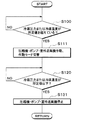
制御装置50は、圧縮機23が停止している場合、図4のフローチャートに示す制御処理を実施する。この制御処理は、車両のイグニッションスイッチがオフされている状態であっても実施される。
When the
ステップS100では、冷凍サイクル22の冷媒の圧力Pcが所定値P1を超えているか否かを判定する。所定値P1は、予め制御装置50に記憶されている。所定値P1は、リリーフ弁25の開弁圧以下の値である。
In step S100, it is determined whether or not the refrigerant pressure Pc in the
冷凍サイクル22の冷媒の圧力Pcが所定値P1を超えていないと判定された場合、ステップS100へ戻り、冷凍サイクル22の冷媒の圧力または温度が所定値を超えていると判定された場合、ステップS110へ進む。
When it is determined that the refrigerant pressure Pc of the
ステップS110では、第1ポンプ11および室外送風機21を作動させるとともに、図1に示す作動モードになるように第1切替弁19および第2切替弁20を切り替える。
In step S110, the
これにより、ラジエータ13および冷却水冷却器14に冷却水が循環するので、冷却水冷却器14で冷却水が冷媒から吸熱し、ラジエータ13で冷却水が外気に放熱する。したがって、冷凍サイクル22の冷媒が冷却されて、冷媒の圧力Pcが低下する。
Thereby, since the cooling water circulates in the
ステップS110において、室外送風機21を作動させず、ラジエータ13で冷却水から外気に自然放熱させてもよい。
In step S110, the
ステップS120では、冷凍サイクル22の冷媒の圧力Pcが所定値P1以下であるか否かを判定する。冷凍サイクル22の冷媒の圧力Pcが所定値P1以下でないと判定された場合、ステップS120へ戻る。一方、冷凍サイクル22の冷媒の圧力Pcが所定値P1以下であると判定された場合、ステップS130へ進み、第1ポンプ11および室外送風機21を停止させる。
In step S120, it is determined whether or not the refrigerant pressure Pc in the
これにより、圧縮機23が停止している場合であっても、冷媒の温度上昇を抑制して冷媒の圧力上昇を抑制できる。
Thereby, even if it is a case where the
例えば、エンジン停止時およびエンジン作動時の両方においてエンジンルーム内の温度が上昇するような状況であっても、冷媒の圧力上昇を抑制できるので、冷凍サイクル22の構成機器を保護できるとともに、圧縮機23を支障なく作動させることができる。
For example, since it is possible to suppress an increase in the pressure of the refrigerant even in a situation where the temperature in the engine room increases both when the engine is stopped and when the engine is operating, the components of the
なお、本例では、ステップS120、ステップS130において、冷凍サイクル22の冷媒の圧力Pcが所定値P1以下であると判定された場合、第1ポンプ11および室外送風機21を停止させるが、ステップS110で第1ポンプ11および室外送風機21を作動させてからの経過時間が所定時間以上になったと判定された場合、第1ポンプ11および室外送風機21を停止させるようにしてもよい。
In this example, when it is determined in steps S120 and S130 that the refrigerant pressure Pc of the
また、ステップS100〜S130において、冷凍サイクル22の冷媒の圧力Pcに応じて第1ポンプ11の作動・停止を切り替えるが、冷凍サイクル22の冷媒の温度Tcに応じて第1ポンプ11の作動・停止を切り替えるようにしてもよい。例えば、冷凍サイクル22の冷媒の温度Tcが所定値T1を超えていると判定された場合、第1ポンプ11を作動させ、冷凍サイクル22の冷媒の温度Tcが所定値T1以下であると判定された場合、第1ポンプ11を停止させるようにしてもよい。この場合、所定値T1は、リリーフ弁25の開弁圧に対応する冷媒の温度未満の値である。
In steps S100 to S130, the operation / stop of the
また、冷凍サイクル22の冷媒の圧力Pcまたは温度Tcが所定値P1、T1をまだ超えていない場合であっても、冷凍サイクル22の冷媒の圧力Pcまたは温度Tcが所定値P1、T1を超えると推定される場合、第1ポンプ11を停止させるようにしてもよい。
Even if the refrigerant pressure Pc or temperature Tc of the
ステップS110では、図1に示す作動モードになるように第1切替弁19および第2切替弁20を切り替えて第1ポンプ11を作動させるが、図5に示す作動モードになるように第1切替弁19および第2切替弁20を切り替えて第2ポンプ12を作動させてもよい。
In step S110, the
これにより、ラジエータ13および冷却水加熱器15に冷却水が循環するので、冷却水加熱器15で冷却水が冷媒から吸熱し、ラジエータ13で冷却水が外気に放熱する。したがって、冷凍サイクル22の冷媒が冷却されて、冷媒の圧力Pcが低下する。
Thereby, since the cooling water circulates in the
本実施形態では、制御装置50(ポンプ制御手段50a)は、圧縮機23が停止している場合、第1ポンプ11を作動させて冷却水を流動させる。第1ポンプ11によって流動される冷却水は、冷媒を冷却するための冷却流体として機能する。
In this embodiment, the control apparatus 50 (pump control means 50a) operates the
これにより、圧縮機23が停止している場合であっても冷媒を冷却できるので、冷媒の圧力が過剰に上昇することを抑制できる。
Thereby, even if it is a case where the
具体的には、制御装置50(ポンプ制御手段50a)は、圧縮機23が停止しており、かつ冷媒の圧力Pcまたは温度Tcが所定値P1、T1を超えている、または超えると推定されると判定した場合、第1ポンプ11および第2ポンプ12のうち少なくとも一方を作動させる。
Specifically, the control device 50 (pump control means 50a) estimates that the
これにより、冷媒の圧力が上昇している、または上昇すると推定される場合に冷却水を流動させることができる。 Thereby, when it is estimated that the pressure of the refrigerant is rising or rising, the cooling water can be flowed.
本実施形態では、ラジエータ13と冷却水加熱器15との間で冷却水が循環する状態と、ラジエータ13と冷却水冷却器14との間で冷却水が循環する状態とを切り替える第1切替弁19および第2切替弁20を備えている。
In the present embodiment, a first switching valve that switches between a state in which cooling water circulates between the
そして、本実施形態では、第1切替弁19および第2切替弁20は、圧縮機23が停止しており、かつ冷媒の圧力Pcまたは温度Tcが所定値P1、T1を超えている、または超えると推定されると判定した場合、ラジエータ13と冷却水冷却器14との間で冷却水が循環する状態に切り替わる作動パターンを備える。
In the present embodiment, in the
これにより、冷却水冷却器14に滞留した冷媒を冷却して極力液相状態にすることができるので、圧縮機23の再起動時に冷凍サイクル22の性能を速やかに発揮させることができる。
Thereby, since the refrigerant | coolant which accumulated in the cooling
本実施形態では、制御装置50(ポンプ制御手段50a)は、ポンプを作動させた後、冷媒の圧力Pcまたは温度Tcが所定値P1、T1以下になった場合、ポンプを停止させる。 In the present embodiment, the control device 50 (pump control means 50a) stops the pump when the refrigerant pressure Pc or the temperature Tc becomes equal to or lower than the predetermined values P1 and T1 after the pump is operated.
これにより、ポンプが必要以上に作動することを抑制できるので、ポンプの消費動力を抑制できる。制御装置50(ポンプ制御手段50a)は、ポンプを作動させた後、所定時間が経過した場合、ポンプを停止させるようにしてよい。 Thereby, since it can suppress that a pump operate | moves more than necessary, the power consumption of a pump can be suppressed. The control device 50 (pump control means 50a) may stop the pump when a predetermined time has elapsed after operating the pump.
本実施形態では、制御装置50(室外送風機制御手段50b)は、圧縮機23が停止しており、かつ冷媒の圧力Pcまたは温度Tcが所定値P1、T1を超えている、または超えると推定されると判定した場合、室外送風機21を作動させる。
In the present embodiment, the control device 50 (outdoor fan control means 50b) is estimated that the
これにより、冷媒を効果的に冷却できるので、冷媒の圧力が過剰に上昇することを効果的に抑制できる。 Thereby, since a refrigerant | coolant can be cooled effectively, it can suppress effectively that the pressure of a refrigerant | coolant rises excessively.
(第2実施形態)
上記実施形態では、冷却水を循環させることによって冷媒を冷却するが、本実施形態では、図6に示すように、冷凍サイクルユニット40に外気を導風することによって冷媒を冷却する。図6における前後上下の矢印は、車両の前後上下方向を示している。
(Second Embodiment)
In the above embodiment, the coolant is cooled by circulating the cooling water, but in this embodiment, the coolant is cooled by introducing the outside air to the
冷凍サイクルユニット40は、導風ダクト60内に配置されている。導風ダクト60は、冷凍サイクルユニット40に外気を導風する導風手段である。
The
導風ダクト60は、外気が流れる外気通路を形成する外気通路形成部材である。導風ダクト60は、エンジンルーム1内を上下方向に延びるように配置されている。
The
導風ダクト60の下端側の開口部60aの開口面は、エンジンルーム1の下部に配置されている。導風ダクト60の下端側の開口部60aの開口面は、車体の最も低い部位よりも上方側に配置されている。換言すれば、地表面から導風ダクト60の下端側の開口部60aの開口面までの鉛直距離LHは、車両の最低地上高LGよりも大きくなっている。
The opening surface of the opening 60 a on the lower end side of the
導風ダクト60の上端側の開口部60bは、車両のカウル4に開口している。カウル4は、車両のワイパー(図示せず)が配置される部材であり、車両のボンネットフード5とフロントガラス(図示せず)との間に配置されている。導風ダクト60には、冷凍サイクルユニット40の冷却水配管40aが貫通している。
An
導風ダクト60内には2つの開閉ドア61が配置されている。2つの開閉ドア61は、導風ダクト60内の外気通路を開閉する外気通路開閉手段である。
Two open /
一方の開閉ドア61は、冷凍サイクルユニット40と導風ダクト60の下端側の開口部60aとの間に配置されており、他方の開閉ドア61は、冷凍サイクルユニット40と導風ダクト60の上端側の開口部60bとの間に配置されている。
One open /
2つの開閉ドア61は、電動アクチュエータ62によって駆動される。電動アクチュエータ62は、2つの開閉ドア61を駆動する駆動手段である。電動アクチュエータ62の作動は、制御装置50によって制御される。
The two open /
制御装置50は、車両が駐車中の場合、図6に示すように2つの開閉ドア61が導風ダクト60内の外気通路を開けるように電動アクチュエータ62の作動を制御する。
When the vehicle is parked, the
これによると、導風ダクト60内の外気通路の外気が冷凍サイクルユニット40によって加熱されて自然対流が発生する。この自然対流によって、図6の矢印に示すように導風ダクト60内の外気通路に外気流れが発生するので、冷凍サイクルユニット40に外気を導風して冷凍サイクルユニット40内の冷媒を冷却できる。
According to this, the outside air in the outside air passage in the
制御装置50は、車両が走行中の場合、図7に示すように2つの開閉ドア61が導風ダクト60内の外気通路を開けるように電動アクチュエータ62の作動を制御する。
When the vehicle is running, the
これによると、導風ダクト60の下端側の開口部60aでは、導風ダクト60の上端側の開口部60bと比較して走行風の流速が高くなるので、負圧が大きくなる。この負圧の差によって、図7の矢印に示すように導風ダクト60内の外気通路に外気流れが発生するので、冷凍サイクルユニット40に外気を導風して冷凍サイクルユニット40内の冷媒を冷却できる。
According to this, in the
制御装置50は、圧縮機23が作動中の場合、図8に示すように2つの開閉ドア61が導風ダクト60内の外気通路を閉じるように電動アクチュエータ62の作動を制御する。
When the
これによると、導風ダクト60内の外気通路に外気流れが発生しないので、圧縮機23、第1ポンプ11および第2ポンプ12等の廃熱によって冷凍サイクルユニット40の雰囲気が加熱され、加熱された外気が冷却水冷却器14を流れる冷媒に吸熱される。そのため、圧縮機23、第1ポンプ11および第2ポンプ12等の廃熱を暖房に利用できる。
According to this, since an outside air flow does not occur in the outside air passage in the
本実施形態では、導風ダクト60によって外気を流動させることができるので、圧縮機23が停止している場合であっても外気を流動させることによって冷媒を冷却でき、ひいては冷媒の圧力が過剰に上昇することを抑制できる。
In this embodiment, since the outside air can be flowed by the
本実施形態では、導風ダクト60は、少なくとも2つの開口部60a、60bを有しており、2つの開口部60a、60bの開口面は、互いに異なる高さに配置されている。これによると、自然対流を利用して外気を流動させることができるので、外気を送風させるための動力を不要としたり低減したりすることができる。
In the present embodiment, the
本実施形態では、導風ダクト60の2つの開口部60a、60bは、車両が走行している場合、一方の開口部60aでは車両の走行風によって他方の開口部60bよりも圧力が低くなるように構成されている。
In the present embodiment, when the vehicle is traveling, the two
これによると、走行風によって生じる圧力の低下を利用して外気を流動させることができるので、外気を送風させるための動力を不要としたり低減したりすることができる。 According to this, since the outside air can be flowed by using the pressure drop caused by the traveling wind, the power for blowing the outside air can be made unnecessary or reduced.
本実施形態では、導風ダクト60内の外気通路を開閉する開閉ドア61を備えるので、外気が流動しない状態に切り替えることができる。そのため、冷媒を冷却する状態と冷却しない状態とを切り替えることができる。
In the present embodiment, since the open /
(第3実施形態)
本実施形態では、図9に示すように、上記第2実施形態に対して、導風ダクト60内の外気通路に送風機63が配置されている。送風機63は、制御装置50によって作動が制御される電動送風機である。
(Third embodiment)
In the present embodiment, as shown in FIG. 9, a
これによると、制御装置50が、2つの開閉ドア61が導風ダクト60内の外気通路を開けるように電動アクチュエータ62の作動を制御するとともに送風機63を作動させることによって、導風ダクト60内の外気通路に外気流れが発生するので、冷凍サイクルユニット40に外気を導風して冷凍サイクルユニット40内の冷媒を冷却できる。
According to this, the
(第4実施形態)
本実施形態では、冷媒の対流を利用して、冷凍サイクルユニット40内の冷媒を冷却する。
(Fourth embodiment)
In the present embodiment, the refrigerant in the
図10に示すように、冷凍サイクル22は、第2膨張弁65および第2蒸発器66を有している。第2膨張弁65および第2蒸発器66は、冷凍サイクル22の冷媒流れにおいて、膨張弁24および冷却水冷却器14と並列に配置されている。
As shown in FIG. 10, the
第2膨張弁65は、冷却水加熱器15から流出した液相冷媒を減圧膨張させる減圧手段である。第2蒸発器66は、第2膨張弁65で減圧膨張された低圧冷媒と車室内への送風空気とを熱交換させて車室内への送風空気を冷却する空気冷却用熱交換器である。第2蒸発器66は、冷媒が流れる流路を形成する冷媒流路形成部材である。
The
第2蒸発器66は、室内空調ユニット27のケーシング28内に配置されている。したがって、第2蒸発器66は、エンジンルーム1に対してファイヤーウォール6で仕切られた車室2内に配置されている。
The
圧縮機23が停止している場合において、エンジンルーム1が高温になって冷凍サイクルユニット40内の冷媒が高温になった場合、第2蒸発器66が配置される車室2内は、冷凍サイクルユニット40が配置されるエンジンルーム1と比較して低温環境となるので、冷媒が自然対流によって冷凍サイクルユニット40と第2蒸発器66との間を循環する。このとき、第2蒸発器66で冷媒が車室内空気に放熱する。そのため、冷凍サイクルユニット40内の冷媒を冷却できる。
When the
本実施形態では、第2蒸発器66は、冷凍サイクルユニット40が配置される領域と比較して空気温度の低い低温領域に配置されている。このため、圧縮機23が停止している場合、冷媒を自然対流で循環させて第2蒸発器66で冷媒を冷却できる。そのため、冷媒の圧力が過剰に上昇することを抑制できる。
In this embodiment, the
(第5実施形態)
上記第4実施形態では、第2蒸発器66で冷媒を放熱させるが、本実施形態では、図11に示すように、冷凍サイクル22を構成する冷媒配管67によって冷媒を放熱させる。
(Fifth embodiment)
In the fourth embodiment, the refrigerant is radiated by the
冷媒配管67は、冷媒が流れる流路を形成する冷媒流路形成部材であり、冷凍サイクル22の冷媒循環流路から分岐している。冷媒循環流路は、冷媒が圧縮機23、冷却水加熱器15、膨張弁24および冷却水冷却器14を循環する流路である。
The
例えば、冷媒配管67は、圧縮機23と冷却水加熱器15との間から分岐している。冷媒配管67は、冷却水加熱器15と膨張弁24との間から分岐していてもよい。冷媒配管67は、膨張弁24と冷却水冷却器14との間から分岐していてもよい。冷媒配管67は、冷却水冷却器14と圧縮機23との間から分岐していてもよい。
For example, the
冷媒配管67は、冷凍サイクルユニット40が配置される領域よりも空気温度の低い低温領域(例えば、エンジンルーム1の下部)まで延びている。
The
冷媒は自然対流によって冷媒配管67を行き来し、冷媒配管67で冷媒が車室内空気に放熱する。そのため、冷凍サイクルユニット40内の冷媒を冷却できる。
The refrigerant travels through the
本例では、冷媒循環流路から分岐する冷媒配管67が低温領域まで延びているが、冷媒循環流路自体が低温領域まで延びていても、同様の作用効果を奏することができる。圧縮機23、冷却水加熱器15、膨張弁24および冷却水冷却器14のうち少なくとも一つが低温領域に配置されていても、同様の作用効果を奏することができる。
In this example, the
(第6実施形態)
上記第1実施形態では、圧縮機23が停止しており、かつ冷媒の圧力Pcまたは温度Tcが所定値P1、T1を超えている、または超えると推定されると判定した場合、ポンプ11および室外送風機21を作動させるが、本実施形態では、圧縮機23が停止しており、かつ冷媒の圧力Pcまたは温度Tcが所定値P1、T1を超えている、または超えると推定されると判定した場合、ポンプ12および室外送風機21に加えて圧縮機23も作動させる。
(Sixth embodiment)
In the first embodiment, when it is determined that the
具体的には、制御装置50は、圧縮機23が停止している場合、図12のフローチャートに示す制御処理を実施する。この制御処理は、車両のイグニッションスイッチがオフされている状態であっても実施される。
Specifically, when the
図12のフローチャートでは、上記第1実施形態で示した図4のフローチャートにおけるステップS110、S130がステップS111、S131に変更されている。 In the flowchart of FIG. 12, steps S110 and S130 in the flowchart of FIG. 4 shown in the first embodiment are changed to steps S111 and S131.
ステップS100において冷凍サイクル22の冷媒の圧力Pcまたは温度Tcが所定値P1、T1を超えていると判定された場合、ステップS111へ進み、図13に示す作動モードになるように第1切替弁19および第2切替弁20を切り替えるとともに、圧縮機23、第2ポンプ12および室外送風機21を作動させる。
When it is determined in step S100 that the refrigerant pressure Pc or temperature Tc of the
図13に示す作動モードでは、ラジエータ13および冷却水加熱器15を有する第2冷却水回路C2が形成される。
In the operation mode shown in FIG. 13, the second cooling water circuit C <b> 2 having the
これにより、圧縮機23が停止している場合であっても、ラジエータ13および冷却水加熱器15に冷却水が循環するので、冷却水加熱器15で冷却水が冷媒から吸熱し、ラジエータ13で冷却水が外気に放熱する。したがって、冷凍サイクル22の冷媒が冷却されて、冷媒の圧力Pcが低下する。
Thereby, even when the
さらに、冷凍サイクル22に冷媒が循環するので、冷却水冷却器14に冷熱が蓄えられる。そのため、上記第1実施形態と比較して、圧縮機23停止後の冷媒の温度上昇が一層抑制されて冷媒の圧力上昇が一層抑制される。
Furthermore, since the refrigerant circulates in the
ステップS120において冷凍サイクル22の冷媒の圧力Pcまたは温度Tcが第2所定値P2、T2以下であると判定された場合、ステップS131へ進み、圧縮機23、第2ポンプ12および室外送風機21を停止させる。第2所定値P2、T2は、予め制御装置50に記憶されている。第2所定値P2、T2は、所定値P1、T1と同じ値であってもよい。
If it is determined in step S120 that the refrigerant pressure Pc or temperature Tc of the
本実施形態では、制御装置50(ポンプ制御手段50a、室外送風機制御手段50b、圧縮機制御手段50c)は、圧縮機23が停止しており、かつ冷媒の圧力Pcまたは温度Tcが所定値P1、T1を超えている、または超えると推定されると判定した場合、圧縮機23、ポンプ12および室外送風機21を作動させる。
In the present embodiment, the control device 50 (pump control means 50a, outdoor fan control means 50b, compressor control means 50c) has the
これによると、圧縮機23が停止した後において冷媒の圧力が上昇している、または上昇すると推定される場合に冷却水を流動させ、かつラジエータ13に外気を送風させ、さらに冷凍サイクル22の冷媒を循環させることができるので、冷媒を確実に冷却でき、ひいては冷媒の圧力が過剰に上昇することを確実に抑制できる。
According to this, when the pressure of the refrigerant has increased or is estimated to increase after the
本実施形態では、制御装置50(ポンプ制御手段50a、室外送風機制御手段50b、圧縮機制御手段50c)は、圧縮機23、ポンプ11、12および室外送風機21を作動させた後、冷媒の圧力Pcまたは温度Tcが第2所定値P2、T2以下になった場合、圧縮機23、ポンプ12および室外送風機21を停止させる。
In the present embodiment, the control device 50 (pump control means 50a, outdoor fan control means 50b, compressor control means 50c) operates the
これにより、圧縮機23、ポンプ12および室外送風機21が必要以上に作動することを抑制できるので、圧縮機23、ポンプ12および室外送風機21の消費動力を抑制できる。
Thereby, since it can suppress that the
制御装置50(ポンプ制御手段50a、室外送風機制御手段50b、圧縮機制御手段50c)は、圧縮機23、ポンプ12および室外送風機21を作動させた後、所定時間が経過した場合、圧縮機23、ポンプ12および室外送風機21を停止させるようにしてよい。
The control device 50 (pump control means 50a, outdoor blower control means 50b, compressor control means 50c) operates the
(第7実施形態)
上記第6実施形態では、圧縮機23が停止しており、かつ冷媒の圧力Pcまたは温度Tcが所定値P1、T1を超えている、または超えると推定されると判定した場合、圧縮機23、第2ポンプ12および室外送風機21を作動させるが、本実施形態では、圧縮機23が停止しており、かつ冷媒の圧力Pcまたは温度Tcが所定値P1、T1を超えている、または超えると推定されると判定した場合、図14に示すように圧縮機23、第2ポンプ12および室外送風機21に加えて第1ポンプ11も作動させる。
(Seventh embodiment)
In the sixth embodiment, when it is determined that the
これによると、第1ポンプ11を作動させるので、冷却水冷却器14で冷却された冷却水が、クーラコア17を有する第1冷却水回路C1に循環する。そのため、第1冷却水回路C1全体に冷熱を蓄えることができるので、上記第6実施形態と比較して圧縮機23停止後の冷媒の温度上昇を一層抑制して冷媒の圧力上昇を一層抑制できる。
According to this, since the
本実施形態では、圧縮機23、第1ポンプ11、第2ポンプ12および室外送風機21を作動させた後、冷媒の圧力Pcまたは温度Tcが第2所定値P2、T2以下になった場合、圧縮機23、第1ポンプ11、第2ポンプ12および室外送風機21を停止させる。
In the present embodiment, after the
これにより、圧縮機23、第1ポンプ11、第2ポンプ12および室外送風機21が必要以上に作動することを抑制できるので、圧縮機23、第1ポンプ11、第2ポンプ12および室外送風機21の消費動力を抑制できる。
Thereby, since it can suppress that the
本実施形態では、圧縮機23が停止しており、かつ冷媒の圧力Pcまたは温度Tcが所定値P1、T1を超えている、または超えると推定されると判定した場合、第1ポンプ11および第2ポンプ12の両方を作動させるが、第1ポンプ11を作動させて第2ポンプ12を作動させないようにしてもよい。
In the present embodiment, when it is determined that the
これによると、冷却水冷却器14を有する第1冷却水回路に冷却水が循環するので、冷媒の温度上昇を抑制して冷媒の圧力上昇を抑制できる。
According to this, since cooling water circulates in the 1st cooling water circuit which has the cooling
(第8実施形態)
上記第6実施形態では、冷凍サイクル22の冷媒の圧力Pcまたは温度Tcが第2所定値P2、T2以下であると判定された場合、圧縮機23、第2ポンプ12および室外送風機21を停止させるが、本実施形態では、図15に示すように、冷却水の温度が冷却水温度所定値T3以下であると判定された場合、圧縮機23、第2ポンプ12および室外送風機21を停止させる。
(Eighth embodiment)
In the said 6th Embodiment, when it determines with the pressure Pc or temperature Tc of the refrigerant | coolant of the refrigerating
具体的には、制御装置50は、圧縮機23が停止している場合、図15のフローチャートに示す制御処理を実施する。この制御処理は、車両のイグニッションスイッチがオフされている状態であっても実施される。
Specifically, when the
図15のフローチャートでは、上記第6実施形態で示した図12のフローチャートにおけるステップS120がステップS121に変更されている。 In the flowchart of FIG. 15, step S120 in the flowchart of FIG. 12 shown in the sixth embodiment is changed to step S121.
ステップS121では、ポンプで循環されている冷却水の温度Twが冷却水温度所定値T3(熱媒体温度所定値)以下であるか否かを判定する。冷却水温度所定値T3は、予め制御装置50に記憶されている。
In step S121, it is determined whether or not the temperature Tw of the cooling water circulated by the pump is equal to or lower than the cooling water temperature predetermined value T3 (heat medium temperature predetermined value). The cooling water temperature predetermined value T3 is stored in the
冷却水の温度Twが冷却水温度所定値T3以下でないと判定された場合、ステップS120へ戻る。一方、冷却水の温度Twが冷却水温度所定値T3以下であると判定された場合、ステップS131へ進み、圧縮機23、第2ポンプ12および室外送風機21を停止させる。
When it is determined that the cooling water temperature Tw is not equal to or lower than the cooling water temperature predetermined value T3, the process returns to step S120. On the other hand, when it is determined that the cooling water temperature Tw is equal to or lower than the cooling water temperature predetermined value T3, the process proceeds to step S131, and the
ここで、冷却水の温度Twは、冷凍サイクル22の冷媒の温度Tcおよび圧力Pcと相関関係がある。具体的には、冷却水の温度Twが高いほど、冷凍サイクル22の冷媒の温度Tcおよび圧力Pcが高くなる。
Here, the temperature Tw of the cooling water has a correlation with the temperature Tc and the pressure Pc of the refrigerant in the
本実施形態では、冷却水の温度Twが冷却水温度所定値T3以下である場合、冷凍サイクル22の冷媒の温度Tcが上述の第2所定値T2以下であると推定でき、冷却水の温度Twが冷却水温度所定値T3以下でない場合、冷凍サイクル22の冷媒の温度Tcが上述の第2所定値T2以下でないと推定できる。
In this embodiment, when the cooling water temperature Tw is equal to or lower than the cooling water temperature predetermined value T3, it can be estimated that the refrigerant temperature Tc of the
同様に、冷却水の温度Twが冷却水温度所定値T3以下である場合、冷凍サイクル22の冷媒の圧力Pcが上述の第2所定値P2以下であると推定でき、冷却水の温度Twが冷却水温度所定値T3以下でない場合、冷凍サイクル22の冷媒の圧力Pcが上述の第2所定値P2以下でないと推定できる。
Similarly, when the cooling water temperature Tw is equal to or lower than the cooling water temperature predetermined value T3, it can be estimated that the refrigerant pressure Pc of the
したがって、本実施形態においても上記第6実施形態と同様の作用効果を奏することができる。 Therefore, also in this embodiment, the same operational effects as those of the sixth embodiment can be obtained.
本実施形態では、制御装置50(ポンプ制御手段50a、室外送風機制御手段50b、圧縮機制御手段50c)は、圧縮機23、ポンプ12および室外送風機21を作動させた後、冷却水の温度Twが冷却水温度所定値T3以下になった場合、圧縮機23、ポンプ12および送風機21を停止させる。
In the present embodiment, the control device 50 (pump control means 50a, outdoor fan control means 50b, compressor control means 50c) operates the
これにより、圧縮機23、ポンプ12および室外送風機21が必要以上に作動することを抑制できるので、圧縮機23、ポンプ12および室外送風機21の消費動力を抑制できる。
Thereby, since it can suppress that the
なお、本実施形態のステップS111において、圧縮機23、第2ポンプ12および室外送風機21に加えて第1ポンプ11も作動させるようにしてもよい。さらに、ステップS131において、圧縮機23、第2ポンプ12および室外送風機21に加えて第1ポンプ11も停止させるようにしてもよい。
In addition, in step S111 of this embodiment, you may make it operate the
(第9実施形態)
上記実施形態では、圧縮機23が停止している場合、冷却水回路の冷却水を冷却させることによって冷媒の圧力上昇を抑制するが、本実施形態では、圧縮機23が停止している場合、エンジン冷却回路C3の冷却水を放熱させることによって冷媒の圧力上昇を抑制する。
(Ninth embodiment)
In the above embodiment, when the
エンジン冷却回路C3は、エンジン70(内燃機関)にエンジン冷却水(内燃機関用冷却媒体)を循環させる冷却水回路であり、エンジン用ポンプ71およびエンジン用ラジエータ72を備えている。
The engine cooling circuit C3 is a cooling water circuit that circulates engine cooling water (internal combustion engine cooling medium) to the engine 70 (internal combustion engine), and includes an
エンジン用ポンプ71は、エンジン冷却回路C3にエンジン冷却水を循環させるポンプである。エンジン用ラジエータ72は、エンジン冷却水と外気とを熱交換させてエンジン冷却水を冷却する熱交換器(内燃機関冷却用熱交換器)である。エンジン用ラジエータ72は、エンジン冷却水の熱を外気に放熱させる放熱器として機能する。エンジン用ラジエータ72には、室外送風機21によって外気が送風される。
The
図17のフローチャートでは、上記第1実施形態で示した図4のフローチャートにおけるステップS110、S130がステップS112、S132に変更されている。 In the flowchart of FIG. 17, steps S110 and S130 in the flowchart of FIG. 4 shown in the first embodiment are changed to steps S112 and S132.
ステップS100において冷凍サイクル22の冷媒の圧力Pcまたは温度Tcが所定値P1、T1を超えていると判定された場合、ステップS112へ進み、室外送風機21を作動させる。
When it is determined in step S100 that the refrigerant pressure Pc or temperature Tc of the
これにより、エンジン用ラジエータ72でエンジン冷却水が外気に放熱して冷却されるので、エンジン70の残熱によるエンジンルーム内の温度上昇が抑制される。そのため、冷凍サイクル22の雰囲気温度の上昇が抑制されるので、冷媒の温度上昇が抑制されて冷媒の圧力上昇が抑制される。
As a result, the
ステップS120において冷凍サイクル22の冷媒の圧力Pcまたは温度Tcが第2所定値P2、T2以下であると判定された場合、ステップS132へ進み、室外送風機21を停止させる。
When it is determined in step S120 that the refrigerant pressure Pc or temperature Tc of the
本実施形態では、エンジン冷却水と空気とを熱交換させるエンジン用ラジエータ72と、エンジン用ラジエータ72に空気を送風する室外送風機21とを備え、制御装置50(室外送風機制御手段50b)は、冷媒の圧力Pcまたは温度Tcが所定値P1、T1を超えている、または超えると推定されると判定した場合、室外送風機21を作動させる。
In the present embodiment, an
これによると、圧縮機23が停止している場合であってもエンジン冷却水を外気に放熱させてエンジンルーム内の温度上昇を抑制できるので、上記第1実施形態と同様に、冷媒の温度上昇を抑制して冷媒の圧力上昇を抑制できる。
According to this, even when the
(他の実施形態)
上記実施形態を適宜組み合わせ可能である。上記実施形態を例えば以下のように種々変形可能である。
(Other embodiments)
The above embodiments can be combined as appropriate. The above embodiment can be variously modified as follows, for example.
(1)冷凍サイクルユニット40に、熱容量の大きな部材を設けてもよい。例えば、冷凍サイクルユニット40の筐体を、熱容量の大きい部材で構成する。これにより、冷凍サイクルユニット40内の冷媒が高温になることを抑制できる。
(1) The
冷却水加熱器15に、外気との熱交換量を制限させる囲いが配置され、囲いと冷却水加熱器15との間に、冷却水加熱器15と接するように蓄冷材が配置されていてもよい。そして、冷凍サイクル22の冷媒の圧力Pcまたは温度Tcが所定値P1、T1を超えていると判定された場合、または冷凍サイクル22の冷媒の圧力Pcまたは温度Tcが所定値P1、T1を超えると推定される場合、第1ポンプ11を停止させるようにしてもよい。
Even if the enclosure which restricts the heat exchange amount with outside air is arrange | positioned at the cooling
(2)冷凍サイクルユニット40がエンジンルーム1に配置されているが、車両の原動機(例えば走行用電動モータ)や燃料電池等の発熱機器が配置される空間に配置されていてもよい。この場合、冷凍サイクルユニット40が、原動機や燃料電池が発生する熱の影響を受けても、冷凍サイクルユニット40内の冷媒の圧力が過剰に上昇することを抑制できる。
(2) Although the
(3)上記実施形態では、クーラコア17を流れる熱媒体として冷却水を用いているが、油などの各種媒体を熱媒体として用いてもよい。
(3) In the above embodiment, the cooling water is used as the heat medium flowing through the
熱媒体として、ナノ流体を用いてもよい。ナノ流体とは、粒子径がナノメートルオーダーのナノ粒子が混入された流体のことである。ナノ粒子を熱媒体に混入させることで、エチレングリコールを用いた冷却水(いわゆる不凍液)のように凝固点を低下させる作用効
果に加えて、次のような作用効果を得ることができる。
A nanofluid may be used as the heat medium. A nanofluid is a fluid in which nanoparticles having a particle size of the order of nanometers are mixed. In addition to the effect of lowering the freezing point as in the case of cooling water using ethylene glycol (so-called antifreeze liquid), the following effects can be obtained by mixing the nanoparticles with the heat medium.
すなわち、特定の温度帯での熱伝導率を向上させる作用効果、熱媒体の熱容量を増加させる作用効果、金属配管の防食効果やゴム配管の劣化を防止する作用効果、および極低温での熱媒体の流動性を高める作用効果を得ることができる。 That is, the effect of improving the thermal conductivity in a specific temperature range, the effect of increasing the heat capacity of the heat medium, the effect of preventing the corrosion of metal pipes and the deterioration of rubber pipes, and the heat medium at an extremely low temperature The effect which improves the fluidity | liquidity of can be acquired.
このような作用効果は、ナノ粒子の粒子構成、粒子形状、配合比率、付加物質によって様々に変化する。 Such effects vary depending on the particle configuration, particle shape, blending ratio, and additional substance of the nanoparticles.
これによると、熱伝導率を向上させることができるので、エチレングリコールを用いた冷却水と比較して少ない量の熱媒体であっても同等の冷却効率を得ることが可能になる。 According to this, since the thermal conductivity can be improved, it is possible to obtain the same cooling efficiency even with a small amount of heat medium as compared with the cooling water using ethylene glycol.
また、熱媒体の熱容量を増加させることができるので、熱媒体自体の蓄冷熱量(顕熱による蓄冷熱)を増加させることができる。 Moreover, since the heat capacity of the heat medium can be increased, the amount of heat stored in the heat medium itself (cold heat stored by sensible heat) can be increased.
蓄冷熱量を増加させることにより、圧縮機23を作動させない状態であっても、ある程度の時間は蓄冷熱を利用した機器の冷却、加熱の温調が実施できるため、車両用熱管理システム10の省動力化が可能になる。
Even if the
ナノ粒子のアスペクト比は50以上であるのが好ましい。十分な熱伝導率を得ることができるからである。なお、アスペクト比は、ナノ粒子の縦×横の比率を表す形状指標である。 The aspect ratio of the nanoparticles is preferably 50 or more. This is because sufficient thermal conductivity can be obtained. The aspect ratio is a shape index that represents the ratio of the vertical and horizontal dimensions of the nanoparticles.
ナノ粒子としては、Au、Ag、CuおよびCのいずれかを含むものを用いることができる。具体的には、ナノ粒子の構成原子として、Auナノ粒子、Agナノワイヤー、CNT(カーボンナノチューブ)、グラフェン、グラファイトコアシェル型ナノ粒子(上記原子を囲むようにカーボンナノチューブ等の構造体があるような粒子体)、およびAuナノ粒子含有CNTなどを用いることができる。 Nanoparticles containing any of Au, Ag, Cu and C can be used. Specifically, Au nanoparticle, Ag nanowire, CNT (carbon nanotube), graphene, graphite core-shell nanoparticle (a structure such as a carbon nanotube surrounding the above atom is included as a constituent atom of the nanoparticle. Particles), Au nanoparticle-containing CNTs, and the like can be used.
(4)上記実施形態の冷凍サイクル22では、冷媒としてフロン系冷媒を用いているが、冷媒の種類はこれに限定されるものではなく、二酸化炭素等の自然冷媒や炭化水素系冷媒等を用いてもよい。
(4) In the
また、上記実施形態の冷凍サイクル22は、高圧側冷媒圧力が冷媒の臨界圧力を超えない亜臨界冷凍サイクルを構成しているが、高圧側冷媒圧力が冷媒の臨界圧力を超える超臨界冷凍サイクルを構成していてもよい。
The
(5)上記実施形態では、車両用熱管理システム10をハイブリッド自動車に適用した例を示したが、エンジンを備えず走行用電動モータから車両走行用の駆動力を得る電気自動車や、水素と酸素との反応で電力を得て走行する燃料電池自動車等に車両用熱管理システム10を適用してもよい。
(5) In the above embodiment, an example in which the vehicle
11 第1ポンプ(ポンプ)
12 第2ポンプ(ポンプ)
13 ラジエータ(熱媒体空気熱交換器)
14 冷却水冷却器(熱媒体冷却用熱交換器)
15 冷却水加熱器(熱媒体加熱用熱交換器)
19 第1切替弁(切替手段)
20 第2切替弁(切替手段)
21 室外送風機(送風手段)
23 圧縮機
24 膨張弁(減圧手段)
50a ポンプ制御手段(流動手段)
50b 室外送風機制御手段(送風制御手段)
11 First pump (pump)
12 Second pump (pump)
13 Radiator (Heat medium air heat exchanger)
14 Cooling water cooler (heat exchanger for heat medium cooling)
15 Cooling water heater (heat exchanger for heat medium heating)
19 1st switching valve (switching means)
20 Second switching valve (switching means)
21 Outdoor blower (blower means)
23
50a Pump control means (flow means)
50b Outdoor fan control means (fan control means)
Claims (11)
前記圧縮機(23)から吐出された冷媒と、空気とは異なる熱媒体とを熱交換させて前記熱媒体を加熱する熱媒体加熱用熱交換器(15)と、
前記圧縮機(23)が停止している場合、前記冷媒を冷却するための冷却流体を流動させる流動手段(50a、60)と、
前記熱媒体加熱用熱交換器(15)で熱交換された前記冷媒を減圧膨張させる減圧手段(24)と、
前記減圧手段(24)で減圧膨張された前記冷媒と前記熱媒体とを熱交換させて前記熱媒体を冷却する熱媒体冷却用熱交換器(14)と、
前記熱媒体と空気とを熱交換させる熱媒体空気熱交換器(13、17、18)と、
前記熱媒体冷却用熱交換器(14)および前記熱媒体空気熱交換器(13、17、18)に前記熱媒体を循環させるポンプ(11、12)とを備え、
前記冷却流体は前記熱媒体であり、
前記流動手段は、前記圧縮機(23)が停止しており、かつ前記冷媒の圧力(Pc)または温度(Tc)が所定値(P1、T1)を超えている、または超えると推定されると判定した場合、前記ポンプ(11、12)を作動させるポンプ制御手段(50a)であることを特徴とする車両用熱管理システム。 A compressor (23) for sucking and discharging refrigerant;
A heat exchanger for heat medium heating (15) for heating the heat medium by exchanging heat between the refrigerant discharged from the compressor (23) and a heat medium different from air;
When the compressor (23) is stopped, flow means (50a, 60) for flowing a cooling fluid for cooling the refrigerant;
Decompression means (24) for decompressing and expanding the refrigerant heat-exchanged in the heat exchanger for heat medium heating (15);
A heat exchanger (14) for cooling a heat medium that cools the heat medium by exchanging heat between the refrigerant and the heat medium decompressed and expanded by the pressure reducing means (24);
A heat medium air heat exchanger (13, 17, 18) for exchanging heat between the heat medium and air;
A pump (11, 12) for circulating the heat medium in the heat medium cooling heat exchanger (14) and the heat medium air heat exchanger (13, 17, 18),
The cooling fluid is the heat medium;
When the compressor (23) is stopped and the refrigerant pressure (Pc) or temperature (Tc) exceeds or exceeds a predetermined value (P1, T1), the flow means is estimated to be exceeded. The vehicle thermal management system, which is a pump control means (50a) for operating the pumps (11, 12) when determined.
前記圧縮機(23)から吐出された冷媒と、空気とは異なる熱媒体とを熱交換させて前記熱媒体を加熱する熱媒体加熱用熱交換器(15)と、
前記圧縮機(23)が停止している場合、前記冷媒を冷却するための冷却流体を流動させる流動手段(50a、60)と、
前記熱媒体と空気とを熱交換させる熱媒体空気熱交換器(13、17、18)と、
前記熱媒体加熱用熱交換器(15)および前記熱媒体空気熱交換器(13、17、18)に前記熱媒体を循環させるポンプ(11、12)とを備え、
前記冷却流体は前記熱媒体であり、
前記流動手段は、前記圧縮機(23)が停止しており、かつ前記冷媒の圧力(Pc)または温度(Tc)が所定値(P1、T1)を超えている、または超えると推定されると判定した場合、前記ポンプ(11、12)を作動させるポンプ制御手段(50a)であることを特徴とする車両用熱管理システム。 A compressor (23) for sucking and discharging refrigerant;
A heat exchanger for heat medium heating (15) for heating the heat medium by exchanging heat between the refrigerant discharged from the compressor (23) and a heat medium different from air;
When the compressor (23) is stopped, flow means (50a, 60) for flowing a cooling fluid for cooling the refrigerant;
A heat medium air heat exchanger (13, 17, 18) for exchanging heat between the heat medium and air;
A heat exchanger (15) for heating the heat medium and a pump (11, 12) for circulating the heat medium to the heat medium air heat exchanger (13, 17, 18),
The cooling fluid is the heat medium;
When the compressor (23) is stopped and the refrigerant pressure (Pc) or temperature (Tc) exceeds or exceeds a predetermined value (P1, T1), the flow means is estimated to be exceeded. The vehicle thermal management system, which is a pump control means (50a) for operating the pumps (11, 12) when determined.
前記圧縮機(23)から吐出された冷媒と、空気とは異なる熱媒体とを熱交換させて前記熱媒体を加熱する熱媒体加熱用熱交換器(15)と、
前記圧縮機(23)が停止している場合、前記冷媒を冷却するための冷却流体を流動させる流動手段(50a、60)と、
前記熱媒体加熱用熱交換器(15)で熱交換された前記冷媒を減圧膨張させる減圧手段(24)と、
前記減圧手段(24)で減圧膨張された前記冷媒と前記熱媒体とを熱交換させて前記熱媒体を冷却する熱媒体冷却用熱交換器(14)と、
前記熱媒体と空気とを熱交換させる熱媒体空気熱交換器(13)と、
前記熱媒体空気熱交換器(13)に前記熱媒体を循環させるポンプ(11、12)と、
前記熱媒体空気熱交換器(13)と前記熱媒体加熱用熱交換器(15)との間で前記熱媒体が循環する状態と、前記熱媒体空気熱交換器(13)と前記熱媒体冷却用熱交換器(14)との間で前記熱媒体が循環する状態とを切り替える切替手段(19、20)とを備え、
前記冷却流体は前記熱媒体であり、
前記流動手段は、前記圧縮機(23)が停止しており、かつ前記冷媒の圧力(Pc)または温度(Tc)が所定値(P1、T1)を超えている、または超えると推定されると判定した場合、前記ポンプ(11、12)を作動させるポンプ制御手段(50a)であることを特徴とする車両用熱管理システム。 A compressor (23) for sucking and discharging refrigerant;
A heat exchanger for heat medium heating (15) for heating the heat medium by exchanging heat between the refrigerant discharged from the compressor (23) and a heat medium different from air;
When the compressor (23) is stopped, flow means (50a, 60) for flowing a cooling fluid for cooling the refrigerant;
Decompression means (24) for decompressing and expanding the refrigerant heat-exchanged in the heat exchanger for heat medium heating (15);
A heat exchanger (14) for cooling a heat medium that cools the heat medium by exchanging heat between the refrigerant and the heat medium decompressed and expanded by the pressure reducing means (24);
A heat medium air heat exchanger (13) for exchanging heat between the heat medium and air;
Pumps (11, 12) for circulating the heat medium in the heat medium air heat exchanger (13);
A state in which the heat medium circulates between the heat medium air heat exchanger (13) and the heat medium heating heat exchanger (15), the heat medium air heat exchanger (13), and the heat medium cooling Switching means (19, 20) for switching between a state in which the heat medium circulates between the heat exchanger (14) for use,
The cooling fluid is the heat medium;
When the compressor (23) is stopped and the refrigerant pressure (Pc) or temperature (Tc) exceeds or exceeds a predetermined value (P1, T1), the flow means is estimated to be exceeded. The vehicle thermal management system, which is a pump control means (50a) for operating the pumps (11, 12) when determined.
前記圧縮機(23)が停止しており、かつ前記冷媒の圧力(Pc)または温度(Tc)が前記所定値(P1、T1)を超えている、または超えると推定されると判定した場合、前記送風手段(21、26)を作動させる送風制御手段(50b、50d)を有していることを特徴とする請求項1ないし6のいずれか1つに記載の車両用熱管理システム。 Blowing means (21, 26) for blowing air to the heat medium air heat exchanger (13, 17, 18),
When it is determined that the compressor (23) is stopped and the pressure (Pc) or temperature (Tc) of the refrigerant exceeds or is estimated to exceed the predetermined values (P1, T1), The vehicle thermal management system according to any one of claims 1 to 6, further comprising a blowing control means (50b, 50d) for operating the blowing means (21, 26).
前記圧縮機(23)から吐出された冷媒と、空気とは異なる熱媒体とを熱交換させて前記熱媒体を加熱する熱媒体加熱用熱交換器(15)と、
前記熱媒体加熱用熱交換器(15)で熱交換された前記冷媒を減圧膨張させる減圧手段(24)と、
前記減圧手段(24)で減圧膨張された前記冷媒と前記熱媒体とを熱交換させて前記熱媒体を冷却する熱媒体冷却用熱交換器(14)と、
前記熱媒体と空気とを熱交換させる熱媒体空気熱交換器(13、17、18)と、
前記熱媒体冷却用熱交換器(14)および前記熱媒体空気熱交換器(13、17、18)に前記熱媒体を循環させるポンプ(11、12)と、
前記熱媒体空気熱交換器(13)に前記空気を送風する送風機(21)と、
前記圧縮機(23)が停止しており、かつ前記冷媒の圧力(Pc)または温度(Tc)が所定値(P1、T1)を超えている、または超えると推定されると判定した場合、前記圧縮機(23)、前記ポンプ(11、12)および前記送風機(21)を作動させる制御手段(50a、50b、50c)を備えることを特徴とする車両用熱管理システム。 A compressor (23) for sucking and discharging refrigerant;
A heat exchanger for heat medium heating (15) for heating the heat medium by exchanging heat between the refrigerant discharged from the compressor (23) and a heat medium different from air;
Decompression means (24) for decompressing and expanding the refrigerant heat-exchanged in the heat exchanger for heat medium heating (15);
A heat exchanger (14) for cooling a heat medium that cools the heat medium by exchanging heat between the refrigerant and the heat medium decompressed and expanded by the pressure reducing means (24);
A heat medium air heat exchanger (13, 17, 18) for exchanging heat between the heat medium and air;
A pump (11, 12) for circulating the heat medium in the heat medium cooling heat exchanger (14) and the heat medium air heat exchanger (13, 17, 18);
A blower (21) for blowing the air to the heat medium air heat exchanger (13);
When it is determined that the compressor (23) is stopped and the pressure (Pc) or temperature (Tc) of the refrigerant exceeds or is estimated to exceed a predetermined value (P1, T1), A vehicle thermal management system comprising control means (50a, 50b, 50c) for operating the compressor (23), the pumps (11, 12) and the blower (21).
前記圧縮機(23)から吐出された冷媒と、空気とは異なる熱媒体とを熱交換させて前記熱媒体を加熱する熱媒体加熱用熱交換器(15)と、
前記熱媒体加熱用熱交換器(15)で熱交換された前記冷媒を減圧膨張させる減圧手段(24)と、
前記減圧手段(24)で減圧膨張された前記冷媒と前記熱媒体とを熱交換させて前記熱媒体を冷却する熱媒体冷却用熱交換器(14)と、
前記熱媒体と空気とを熱交換させる熱媒体空気熱交換器(13、17、18)と、
前記熱媒体冷却用熱交換器(14)および前記熱媒体空気熱交換器(13、17、18)に前記熱媒体を循環させるポンプ(11、12)と、
内燃機関(70)を冷却する内燃機関用冷却媒体と空気とを熱交換させる内燃機関冷却用熱交換器(72)と、
前記内燃機関冷却用熱交換器(72)に空気を送風する送風機(21)と、
前記内燃機関(70)および前記圧縮機(23)が停止しており、かつ前記冷媒の圧力(Pc)または温度(Tc)が所定値(P1、T1)を超えている、または超えると推定されると判定した場合、前記送風機(21)を作動させる送風機制御手段(50b)とを備えることを特徴とする車両用熱管理システム。 A compressor (23) for sucking and discharging refrigerant;
A heat exchanger for heat medium heating (15) for heating the heat medium by exchanging heat between the refrigerant discharged from the compressor (23) and a heat medium different from air;
Decompression means (24) for decompressing and expanding the refrigerant heat-exchanged in the heat exchanger for heat medium heating (15);
A heat exchanger (14) for cooling a heat medium that cools the heat medium by exchanging heat between the refrigerant and the heat medium decompressed and expanded by the pressure reducing means (24);
A heat medium air heat exchanger (13, 17, 18) for exchanging heat between the heat medium and air;
A pump (11, 12) for circulating the heat medium in the heat medium cooling heat exchanger (14) and the heat medium air heat exchanger (13, 17, 18);
An internal combustion engine cooling heat exchanger (72) for exchanging heat between the cooling medium for cooling the internal combustion engine (70) and the air; and
A blower (21) for blowing air to the heat exchanger (72) for cooling the internal combustion engine;
It is estimated that the internal combustion engine (70) and the compressor (23) are stopped and the pressure (Pc) or temperature (Tc) of the refrigerant exceeds or exceeds a predetermined value (P1, T1). When it determines with it, it is provided with the air blower control means (50b) which operates the air blower (21), The thermal management system for vehicles characterized by the above-mentioned.
Priority Applications (5)
| Application Number | Priority Date | Filing Date | Title |
|---|---|---|---|
| JP2014081927A JP6052222B2 (en) | 2013-06-18 | 2014-04-11 | Thermal management system for vehicles |
| CN201480034712.3A CN105324259B (en) | 2013-06-18 | 2014-06-03 | Vehicular heat management system |
| US14/898,718 US9994087B2 (en) | 2013-06-18 | 2014-06-03 | Vehicular heat management system |
| PCT/JP2014/002922 WO2014203476A1 (en) | 2013-06-18 | 2014-06-03 | Vehicular heat management system |
| DE112014002874.6T DE112014002874B4 (en) | 2013-06-18 | 2014-06-03 | Vehicle thermal management system |
Applications Claiming Priority (3)
| Application Number | Priority Date | Filing Date | Title |
|---|---|---|---|
| JP2013127529 | 2013-06-18 | ||
| JP2013127529 | 2013-06-18 | ||
| JP2014081927A JP6052222B2 (en) | 2013-06-18 | 2014-04-11 | Thermal management system for vehicles |
Publications (3)
| Publication Number | Publication Date |
|---|---|
| JP2015024806A JP2015024806A (en) | 2015-02-05 |
| JP2015024806A5 JP2015024806A5 (en) | 2015-08-13 |
| JP6052222B2 true JP6052222B2 (en) | 2016-12-27 |
Family
ID=52104228
Family Applications (1)
| Application Number | Title | Priority Date | Filing Date |
|---|---|---|---|
| JP2014081927A Expired - Fee Related JP6052222B2 (en) | 2013-06-18 | 2014-04-11 | Thermal management system for vehicles |
Country Status (5)
| Country | Link |
|---|---|
| US (1) | US9994087B2 (en) |
| JP (1) | JP6052222B2 (en) |
| CN (1) | CN105324259B (en) |
| DE (1) | DE112014002874B4 (en) |
| WO (1) | WO2014203476A1 (en) |
Cited By (3)
| Publication number | Priority date | Publication date | Assignee | Title |
|---|---|---|---|---|
| US20210213799A1 (en) * | 2020-01-09 | 2021-07-15 | Denso Corporation | Vehicle air conditioning device |
| US11383583B2 (en) | 2018-04-06 | 2022-07-12 | Denso Corporation | Thermal management device for vehicle |
| US11499757B2 (en) | 2017-10-26 | 2022-11-15 | Denso Corporation | Vehicular heat management system |
Families Citing this family (30)
| Publication number | Priority date | Publication date | Assignee | Title |
|---|---|---|---|---|
| JP2016190513A (en) * | 2015-03-30 | 2016-11-10 | 富士重工業株式会社 | Vehicular air-conditioner device |
| JP6540180B2 (en) * | 2015-04-14 | 2019-07-10 | 株式会社デンソー | Vehicle thermal management system |
| JP6433403B2 (en) * | 2015-10-02 | 2018-12-05 | トヨタ自動車株式会社 | Vehicle thermal management device |
| JP6663676B2 (en) * | 2015-10-02 | 2020-03-13 | 株式会社デンソー | Vehicle heat management device |
| KR101846923B1 (en) * | 2016-11-01 | 2018-04-09 | 현대자동차 주식회사 | Heat pump system for vehicle |
| KR101846915B1 (en) | 2016-11-01 | 2018-05-28 | 현대자동차 주식회사 | Heat pump system for vehicle |
| CN106739943A (en) * | 2017-01-04 | 2017-05-31 | 上海爱斯达克汽车空调系统有限公司 | A kind of vehicle with heat-exchange system |
| JP6791052B2 (en) * | 2017-07-31 | 2020-11-25 | 株式会社デンソー | Air conditioner |
| CN107650619A (en) * | 2017-10-19 | 2018-02-02 | 天津商业大学 | A kind of automotive air-conditioning system of safety and environmental protection |
| KR102474356B1 (en) * | 2017-11-10 | 2022-12-05 | 현대자동차 주식회사 | Heat pump system for vehicle |
| CN107839433B (en) * | 2017-11-28 | 2024-02-23 | 中国第一汽车股份有限公司 | Whole vehicle thermal management system of plug-in hybrid electric vehicle |
| US10551276B2 (en) * | 2017-12-05 | 2020-02-04 | Electricfil Corporation | Vehicle coolant flow and coolant quality sensor assembly |
| KR102575170B1 (en) * | 2018-06-15 | 2023-09-05 | 현대자동차 주식회사 | Heat pump system for vehicle |
| JP7268976B2 (en) * | 2018-08-10 | 2023-05-08 | サンデン株式会社 | Vehicle air conditioner |
| US11065936B2 (en) * | 2018-08-10 | 2021-07-20 | GM Global Technology Operations LLC | Vehicle thermal system architecture |
| JP7372732B2 (en) * | 2018-12-19 | 2023-11-01 | サンデン株式会社 | Vehicle air conditioner |
| WO2020129258A1 (en) * | 2018-12-21 | 2020-06-25 | 本田技研工業株式会社 | Vehicle |
| JP7215162B2 (en) * | 2018-12-27 | 2023-01-31 | 株式会社デンソー | vehicle air conditioner |
| CN113557353B (en) * | 2019-03-08 | 2024-03-08 | 翰昂汽车零部件有限公司 | Thermal management system for a vehicle |
| JP7202223B2 (en) * | 2019-03-11 | 2023-01-11 | 株式会社Subaru | vehicle |
| JP7233986B2 (en) * | 2019-03-12 | 2023-03-07 | サンデン株式会社 | Vehicle air conditioner |
| JP7230642B2 (en) * | 2019-03-29 | 2023-03-01 | 株式会社デンソー | refrigeration cycle equipment |
| JP7111064B2 (en) * | 2019-06-11 | 2022-08-02 | トヨタ自動車株式会社 | CO2 recovery system |
| AU2020427646B2 (en) * | 2020-02-06 | 2023-09-28 | Mitsubishi Electric Corporation | Outdoor unit of air-conditioning apparatus |
| DE102020129328A1 (en) * | 2020-11-06 | 2022-05-12 | Rheinmetall Invent GmbH | heating and cooling system and vehicle |
| JP2022108685A (en) * | 2021-01-13 | 2022-07-26 | 本田技研工業株式会社 | vehicle |
| JP2022190760A (en) * | 2021-06-15 | 2022-12-27 | トヨタ自動車株式会社 | Heat management system |
| US11541719B1 (en) | 2021-07-14 | 2023-01-03 | GM Global Technology Operations LLC | Active thermal management systems and control logic for heat exchanger storage of refrigerant |
| US20230031346A1 (en) * | 2021-07-29 | 2023-02-02 | Rivian Ip Holdings, Llc | Heating, ventilation, and air conditioning case with extractor port to ambient |
| JP2024103299A (en) * | 2023-01-20 | 2024-08-01 | サンデン株式会社 | Heat exchanger and vehicle air conditioning system |
Family Cites Families (12)
| Publication number | Priority date | Publication date | Assignee | Title |
|---|---|---|---|---|
| JP3125198B2 (en) * | 1991-12-04 | 2001-01-15 | 本田技研工業株式会社 | Battery temperature control device for electric vehicle |
| FR2808738B1 (en) * | 2000-05-15 | 2002-08-23 | Peugeot Citroen Automobiles Sa | IMPROVED HEAT PUMP THERMAL REGULATION DEVICE FOR A MOTOR VEHICLE |
| FR2812243B1 (en) * | 2000-07-28 | 2003-05-09 | Valeo Climatisation | DEVICE FOR HEATING AND AIR CONDITIONING THE INTERIOR OF A MOTOR VEHICLE |
| JP2002248932A (en) * | 2001-02-26 | 2002-09-03 | Sanyo Electric Co Ltd | Onboard air conditioner |
| JP2005306203A (en) | 2004-04-21 | 2005-11-04 | Sanden Corp | Air conditioning system for vehicle |
| JP2008265686A (en) * | 2007-04-24 | 2008-11-06 | Denso Corp | Refrigeration cycle device for vehicle |
| CN102112819B (en) * | 2008-10-29 | 2013-07-31 | 三菱电机株式会社 | Air conditioner |
| JP5396246B2 (en) * | 2009-11-18 | 2014-01-22 | 株式会社日立製作所 | Air conditioner for vehicles |
| DE112011102775A5 (en) * | 2010-08-24 | 2013-07-04 | Ixetic Bad Homburg Gmbh | Heating / cooling device and heating / cooling module for a heating / cooling device |
| US8899062B2 (en) | 2011-02-17 | 2014-12-02 | Delphi Technologies, Inc. | Plate-type heat pump air conditioner heat exchanger for a unitary heat pump air conditioner |
| JP5589967B2 (en) * | 2011-06-13 | 2014-09-17 | 株式会社デンソー | Temperature control device for vehicles |
| DE102011082584A1 (en) * | 2011-09-13 | 2013-03-14 | Behr Gmbh & Co. Kg | Device for controlling the temperature of a plurality of components of a vehicle and vehicle system |
-
2014
- 2014-04-11 JP JP2014081927A patent/JP6052222B2/en not_active Expired - Fee Related
- 2014-06-03 US US14/898,718 patent/US9994087B2/en not_active Expired - Fee Related
- 2014-06-03 DE DE112014002874.6T patent/DE112014002874B4/en active Active
- 2014-06-03 WO PCT/JP2014/002922 patent/WO2014203476A1/en active Application Filing
- 2014-06-03 CN CN201480034712.3A patent/CN105324259B/en active Active
Cited By (4)
| Publication number | Priority date | Publication date | Assignee | Title |
|---|---|---|---|---|
| US11499757B2 (en) | 2017-10-26 | 2022-11-15 | Denso Corporation | Vehicular heat management system |
| US11383583B2 (en) | 2018-04-06 | 2022-07-12 | Denso Corporation | Thermal management device for vehicle |
| US20210213799A1 (en) * | 2020-01-09 | 2021-07-15 | Denso Corporation | Vehicle air conditioning device |
| US11731484B2 (en) * | 2020-01-09 | 2023-08-22 | Denso Corporation | Vehicle air conditioning device |
Also Published As
| Publication number | Publication date |
|---|---|
| CN105324259A (en) | 2016-02-10 |
| CN105324259B (en) | 2017-05-24 |
| DE112014002874B4 (en) | 2024-09-12 |
| WO2014203476A1 (en) | 2014-12-24 |
| JP2015024806A (en) | 2015-02-05 |
| DE112014002874T5 (en) | 2016-03-03 |
| US20160129756A1 (en) | 2016-05-12 |
| US9994087B2 (en) | 2018-06-12 |
Similar Documents
| Publication | Publication Date | Title |
|---|---|---|
| JP6052222B2 (en) | Thermal management system for vehicles | |
| JP6303615B2 (en) | Thermal management system for vehicles | |
| JP6398764B2 (en) | Thermal management system for vehicles | |
| JP6112039B2 (en) | Thermal management system for vehicles | |
| JP6540180B2 (en) | Vehicle thermal management system | |
| JP6065779B2 (en) | Thermal management system for vehicles | |
| JP6206231B2 (en) | Thermal management system for vehicles | |
| JP6197671B2 (en) | Air conditioner | |
| JP5983187B2 (en) | Thermal management system for vehicles | |
| JP6233009B2 (en) | Air conditioner for vehicles | |
| JP6167892B2 (en) | Air conditioner for vehicles | |
| JP5949668B2 (en) | Thermal management system for vehicles | |
| JP6663676B2 (en) | Vehicle heat management device | |
| JP2015030279A (en) | Vehicular air-conditioner | |
| WO2015115050A1 (en) | Vehicle heat management system | |
| JP2014218211A (en) | Vehicle heat management system | |
| JP6083304B2 (en) | Thermal management system for vehicles | |
| JP6197642B2 (en) | Air conditioner for vehicles | |
| WO2017098795A1 (en) | Refrigeration cycle device | |
| JP6060799B2 (en) | Air conditioner for vehicles | |
| JP2015163499A (en) | Air conditioner for vehicle | |
| JP6341118B2 (en) | Refrigeration cycle equipment |
Legal Events
| Date | Code | Title | Description |
|---|---|---|---|
| A521 | Request for written amendment filed |
Free format text: JAPANESE INTERMEDIATE CODE: A523 Effective date: 20150629 |
|
| A621 | Written request for application examination |
Free format text: JAPANESE INTERMEDIATE CODE: A621 Effective date: 20160422 |
|
| A131 | Notification of reasons for refusal |
Free format text: JAPANESE INTERMEDIATE CODE: A131 Effective date: 20160830 |
|
| A521 | Request for written amendment filed |
Free format text: JAPANESE INTERMEDIATE CODE: A523 Effective date: 20161004 |
|
| TRDD | Decision of grant or rejection written | ||
| A01 | Written decision to grant a patent or to grant a registration (utility model) |
Free format text: JAPANESE INTERMEDIATE CODE: A01 Effective date: 20161101 |
|
| A61 | First payment of annual fees (during grant procedure) |
Free format text: JAPANESE INTERMEDIATE CODE: A61 Effective date: 20161114 |
|
| R151 | Written notification of patent or utility model registration |
Ref document number: 6052222 Country of ref document: JP Free format text: JAPANESE INTERMEDIATE CODE: R151 |
|
| R250 | Receipt of annual fees |
Free format text: JAPANESE INTERMEDIATE CODE: R250 |
|
| R250 | Receipt of annual fees |
Free format text: JAPANESE INTERMEDIATE CODE: R250 |
|
| LAPS | Cancellation because of no payment of annual fees |