JP6036048B2 - Vehicle control device - Google Patents
Vehicle control device Download PDFInfo
- Publication number
- JP6036048B2 JP6036048B2 JP2012198764A JP2012198764A JP6036048B2 JP 6036048 B2 JP6036048 B2 JP 6036048B2 JP 2012198764 A JP2012198764 A JP 2012198764A JP 2012198764 A JP2012198764 A JP 2012198764A JP 6036048 B2 JP6036048 B2 JP 6036048B2
- Authority
- JP
- Japan
- Prior art keywords
- battery
- relay
- voltage
- vehicle
- sub
- Prior art date
- Legal status (The legal status is an assumption and is not a legal conclusion. Google has not performed a legal analysis and makes no representation as to the accuracy of the status listed.)
- Active
Links
Images


Description
本発明は、車両の制御装置に関する。 The present invention relates to a vehicle control device.
従来、エンジンの自動停止・自動再始動が可能な車両の制御装置において、スタータと電気的に結合されたメインバッテリと、車両の電気負荷と電気的に結合されたサブバッテリと、メインバッテリおよびサブバッテリを電気的に結合するか否かを自身のオン/オフで切替可能なリレーとを備え、エンジン自動停止後の再始動時に、リレーをオフにしてスタータを作動させる技術が知られている(特許文献1参照)。これにより、スタータの作動時に、サブバッテリの電圧低下(瞬低)が発生することを防いで、電気負荷への電力供給不足を防止することができる。また、リレーをオンにして、エンジンによって駆動されるオルタネータによってメインバッテリとサブバッテリの充電を行うこともできる。 Conventionally, in a vehicle control device capable of automatically stopping and restarting an engine, a main battery electrically coupled to a starter, a sub battery electrically coupled to an electric load of the vehicle, a main battery and a sub battery There is known a technology that includes a relay that can be switched on / off by whether or not the battery is electrically coupled, and operates the starter by turning off the relay when restarting after automatic engine stop ( Patent Document 1). Thereby, it is possible to prevent the voltage drop (instantaneous drop) of the sub-battery from occurring when the starter is operated, and it is possible to prevent a shortage of power supply to the electric load. Further, the main battery and the sub battery can be charged by the alternator driven by the engine with the relay turned on.
しかしながら、上述した車両の制御装置では、メインバッテリとサブバッテリ間のリレーがオフし続けた状態となるオフ固着故障が発生した場合、以下のような問題が生じる。すなわち、リレーをオンにする指令を出して、オルタネータによってメインバッテリとサブバッテリの充電をしようとした場合にリレーのオフ固着故障が発生していると、サブバッテリの充電を行うことができずに電圧が低下し、サブバッテリから電気負荷への電力供給不足が生じる可能性がある。 However, in the vehicle control apparatus described above, the following problem occurs when an off-fixing failure occurs in which the relay between the main battery and the sub-battery continues to be turned off. In other words, if a relay off-fixing failure occurs when a command to turn on the relay is issued and the alternator tries to charge the main battery and the sub battery, the sub battery cannot be charged. The voltage decreases, and there is a possibility that insufficient power supply from the sub-battery to the electric load occurs.
本発明は、メインバッテリとサブバッテリ間のリレーのオフ固着故障を検出することを目的とする。 An object of the present invention is to detect an off-fixation failure of a relay between a main battery and a sub battery.
本発明による車両の制御装置は、エンジンの出力軸に機械的に結合されたモータジェネレータと、モータジェネレータと電気的に結合された第1バッテリと、車両の電気負荷と電気的に結合された第2バッテリと、第1バッテリおよび第2バッテリを電気的に結合するか否かを自身のオン/オフにより切替可能なリレーと、モータジェネレータの力行運転中はリレーをオフにし、モータジェネレータの回生運転中はリレーをオンにするリレー制御手段を備える。この車両の制御装置はさらに、リレーをオンにする指令が出されている状態で、第1バッテリの電圧および第2バッテリの電圧の差が所定電圧より大きくなった場合に、リレーがオフ固着していると判定するリレー故障診断手段を備える。リレー故障診断手段は、リレーをオンにする指令が出されている状態で、第1バッテリの電圧および第2バッテリの電圧の差が第1の所定電圧より高い第2の所定電圧より大きい状態で第1の所定時間より短い第2の所定時間を経過すると、リレーがオフ固着していると判定する。第1の所定電圧は、定常電流が流れる定常状態において発生する第1バッテリと第2バッテリとの間の最大電圧差よりも高い。第2の所定電圧は、第1バッテリと第2バッテリとの間に過渡電流が流れる状態において発生する第1バッテリと第2バッテリとの間の最大電圧差よりも高い。 A vehicle control apparatus according to the present invention includes a motor generator mechanically coupled to an output shaft of an engine, a first battery electrically coupled to the motor generator, and a first battery electrically coupled to an electric load of the vehicle. 2 battery, a relay that can switch whether to electrically couple the first battery and the second battery by ON / OFF of its own, and the relay is turned off during the power running operation of the motor generator, and the regenerative operation of the motor generator A relay control means for turning on the relay is provided. In this vehicle control device, the relay is fixed off when the difference between the voltage of the first battery and the voltage of the second battery becomes larger than a predetermined voltage in a state where a command to turn on the relay is issued. Relay failure diagnosis means for determining that the The relay failure diagnosing means is in a state in which a command to turn on the relay is issued and a difference between the voltage of the first battery and the voltage of the second battery is larger than a second predetermined voltage higher than the first predetermined voltage. When a second predetermined time shorter than the first predetermined time elapses, it is determined that the relay is fixed off. The first predetermined voltage is higher than the maximum voltage difference between the first battery and the second battery that occurs in a steady state in which a steady current flows. The second predetermined voltage is higher than the maximum voltage difference between the first battery and the second battery that occurs when a transient current flows between the first battery and the second battery.
本発明によれば、モータジェネレータの回生運転中であって、かつ、リレーをオンにする指令が出されている状態で、第1バッテリの電圧および第2バッテリの電圧の差が所定電圧より大きくなった場合に、リレーがオフ固着していると判定するので、リレーオフ固着故障を精度良く検出することができる。 According to the present invention, the difference between the voltage of the first battery and the voltage of the second battery is larger than the predetermined voltage while the motor generator is in the regenerative operation and the command to turn on the relay is issued. In this case, since it is determined that the relay is stuck off, a relay off stuck failure can be detected with high accuracy.
図1は、一実施の形態における車両の制御装置の概略構成図である。図1において、車両1には、エンジン2、モータジェネレータ21、エアコン用コンプレッサ31が設けられている。具体的には、エンジン2の出力軸3、モータジェネレータ21の回転軸22、エアコン用コンプレッサ31の回転軸32が平行に配置され、出力軸3の一端にクランクプーリ4が、回転軸22、32に各プーリ23、33が取り付けられている。これら3つの各プーリ4、23、33にはベルト5が掛け回され、エンジン2の出力軸3、回転軸23、33の間は、ベルト5によって動力が伝達(伝導)される。
FIG. 1 is a schematic configuration diagram of a vehicle control device according to an embodiment. In FIG. 1, a
スタータ6は、エンジン2の始動に用いられる。エンジン2の出力軸3の他端には、トルクコンバータ8、ベルト式の自動変速機9が接続されている。トルクコンバータ8は、図示しないポンプインペラ、タービンランナを有する。ベルト式の自動変速機9は、図示しないプライマリプーリ、セカンダリプーリ、これらプーリに掛け回されるスチールベルトを有する。エンジン2の回転駆動力は、これらトルクコンバータ8、自動変速機9を介して、最終的に車両駆動輪(図示しない)に伝達される。
The
車両1の電源として、メインバッテリ41とサブバッテリ42が設けられている。いずれも14Vバッテリである。2つのバッテリ41、42の間には、並列された2つのリレー43a、43bが接続されている。2つのリレー43a、43bを設けているのは、一方のリレーが故障した場合のバックアップのためであり、また、1つのリレーだけを設ける場合に比べて、リレーの耐久作動回数を延ばすためである。
As a power source for the
上記のスタータ6、モータジェネレータ21は、メインバッテリ41とリレー43a、43bの間に接続され、電力はメインバッテリ41から供給される。なお、モータジェネレータ21は、交流機から構成されているため、メインバッテリ41からの直流を交流に変換するインバータ24を付属している。
The
電気負荷44は、バッテリの電圧が瞬間的に低下する瞬低が起こっても自身の動作には影響がない負荷であり、メインバッテリ41から電力が供給される。一方、電気負荷45は、瞬低が起こると自身の動作に影響が出る負荷であり、サブバッテリ42から電力が供給される。
The
エンジンコントロールモジュール(ECM)51は、エンジン2、スタータ6、モータジェネレータ21、および、リレー43a、43bを制御する。例えば、エンジンコントロールモジュール51は、モータジェネレータ21の力行運転中はリレー43a、43bをオフにしてメインバッテリ41およびサブバッテリ42の電気的結合を切断し、モータジェネレータ21の回生運転中はリレー43aまたは43bをオンにしてメインバッテリ41およびサブバッテリ42を電気的に結合する。また、エンジンコントロールモジュール51は、後述する方法により、リレー43a、43bのオフ固着故障が発生していないか診断する。
The engine control module (ECM) 51 controls the
図2はガソリンエンジンの制御システム図である。各吸気ポート(図示しない)には、燃料噴射弁7が設けられている。燃料噴射弁7は、燃料をエンジン2に間欠的に供給するものである。
FIG. 2 is a control system diagram of a gasoline engine. Each intake port (not shown) is provided with a
吸気通路11には、電子制御のスロットル弁12が設けられ、スロットルモータ13によってスロットル弁12の開度(以下、「スロットル開度」という。)が制御される。実際のスロットル開度は、スロットルセンサ14により検出され、エンジンコントロールモジュール51に入力される。
The
エンジンコントロールモジュール51には、アクセルセンサ53からのアクセル開度(アクセルペダル52の踏込量)の信号、クランク角センサ54からのクランク角の信号、エアフローメータ55からの吸入空気量の信号が入力される。クランク角センサ54の信号からは、エンジン2の回転速度が算出される。エンジンコントロールモジュール51は、これらの信号に基づいて、目標吸入空気量及び目標燃料噴射量を算出し、目標吸入空気量及び目標燃料噴射量が得られるように、スロットルモータ13及び各燃料噴射弁7に指令を出す。
The
ここで、吸入空気量の制御について概説する(特開平9−287513号公報参照)。アクセル開度APOとエンジン回転速度Neとから所定のマップを検索することにより、目標基本吸入空気量及び目標当量比tDMLをそれぞれ算出する。目標基本吸入空気量を目標当量比tDMLで除算した値を目標吸入空気量とする。そして、この目標吸入空気量とエンジン回転速度から所定のマップを検索することにより、目標スロットル弁開度を求める。目標スロットル弁開度を指令値に変換して、スロットルモータ13に出力する。
Here, the control of the intake air amount will be outlined (refer to Japanese Patent Laid-Open No. 9-287513). By searching a predetermined map from the accelerator opening APO and the engine speed Ne, the target basic intake air amount and the target equivalent ratio tDML are respectively calculated. A value obtained by dividing the target basic intake air amount by the target equivalent ratio tDML is set as the target intake air amount. The target throttle valve opening is obtained by searching a predetermined map from the target intake air amount and the engine speed. The target throttle valve opening is converted into a command value and output to the
次に、燃料噴射(燃料噴射量及び燃料噴射時期)の制御について概説する。エアフローメータ55の出力をA/D変換し、リニアライズして吸入空気量Qaを算出する。この吸入空気量Qaとエンジン回転速度Neから、ほぼ理論空燃比(当量比=1.0)の混合気が得られる基本噴射パルス幅Tp0[ms]を、Tp0=K×Qa/Ne(ただし、Kは定数)として求める。次に、
Tp=Tp0×Fload+Tp-1×(1−Fload)
ただし、Fload:加重平均係数、
Tp-1:前回のTp、
の式によりシリンダ空気量相当パルス幅Tp[ms]を求める。これは、シリンダ(燃焼室)に流入する空気量(つまりシリンダ空気量)がエアフローメータ部での吸入空気量に対して応答遅れを有するので、この応答遅れを一次遅れで近似したものである。一次遅れの係数である加重平均係数Fload[無名数]は、回転速度Ne及びシリンダ容積Vの積Ne・Vと吸気管の総流路面積Aaから所定のマップを検索することにより求める。このようにして求めたシリンダ空気量相当パルス幅Tpに基づいて、燃料噴射弁7に与える燃料噴射パルス幅Ti[ms]を、
Ti=Tp×tDML×(α+αm−1)×2+Ts
ただし、tDML:目標当量比[無名数]、
α:空燃比フィードバック補正係数[無名数]、
αm:空燃比学習値[無名数]、
Ts:無効噴射パルス幅[無名数]、
の式により算出する。そして、所定の燃料噴射時期になったときに、この燃料噴射パルス幅Tiの期間、燃料噴射弁7を開く。
Next, control of fuel injection (fuel injection amount and fuel injection timing) will be outlined. The output of the
Tp = Tp0 × Fload + Tp−1 × (1−Fload)
Where Fload: weighted average coefficient,
Tp-1: Previous Tp,
The cylinder air amount equivalent pulse width Tp [ms] is obtained by the following equation. This is because the air amount flowing into the cylinder (combustion chamber) (that is, the cylinder air amount) has a response delay with respect to the intake air amount in the air flow meter section, and this response delay is approximated by a primary delay. The weighted average coefficient Fload [nameless number] which is a coefficient of the first order lag is obtained by searching a predetermined map from the product Ne · V of the rotational speed Ne and the cylinder volume V and the total flow path area Aa of the intake pipe. Based on the cylinder air amount equivalent pulse width Tp thus determined, the fuel injection pulse width Ti [ms] given to the
Ti = Tp × tDML × (α + αm−1) × 2 + Ts
However, tDML: target equivalent ratio [anonymous number],
α: Air-fuel ratio feedback correction coefficient [anonymous number]
αm: Air-fuel ratio learning value [anonymous number]
Ts: Invalid injection pulse width [anonymous number],
It is calculated by the following formula. When the predetermined fuel injection timing comes, the
なお、ガソリンエンジン2では、燃焼室(シリンダ)に臨んで点火プラグを備えている。エンジンコントロールモジュール51は、圧縮上死点前の所定の時期に点火コイルの一次側電流を遮断することにより点火プラグに火花を発生させ、これによって燃焼室内の混合気に点火する。
The
また、エンジンコントロールモジュール51は、スタータスイッチ56からの信号に基づいて、初回の始動要求があると判断したときには、スタータ6を駆動しエンジン2を始動させる。
When the
エンジンコントロールモジュール51は、燃費向上を目的として、アイドルストップ制御を行う。すなわち、アクセルペダル52が踏み込まれておらず(APO=0)、ブレーキペダル57が踏み込まれ(ブレーキスイッチ58がON)、かつ車両1が停止状態にある(車速VSP=0)ときに、アイドルストップ許可条件が成立する。アイドルストップ許可条件が成立すると、燃料噴射弁7から吸気ポートへの燃料噴射を遮断して、エンジン2を停止する。これにより、無駄な燃料消費を低減する。
The
その後、アイドルストップ状態で、アクセルペダル52が踏み込まれたり、ブレーキペダル57が戻される(ブレーキスイッチ58がOFF)などすると、アイドルストップ許可条件が不成立となる。アイドルストップ許可条件が不成立となると、モータジェネレータ21をスタータとして用いてエンジン2をクランキングし、燃料噴射弁7からの燃料噴射と点火プラグによる火花点火とを再開して、エンジン2を再始動する。
Thereafter, when the
このように、モータジェネレータ21をアイドルストップからのエンジン再始動用として専ら用いることで、スタータ6の使用頻度を減らして、スタータ6を保護する。なお、スタータ6やモータジェネレータ21を駆動するときには、エンジンコントロールモジュール51により、2つのリレー43a、43bをともに遮断して、メインバッテリ41とサブバッテリ42を電気的に切り離す。これによって、エンジン2の始動操作に伴ってサブバッテリ42の電圧が変動することを防止する。
Thus, by using the
図1に戻り、説明を続ける。車両1には、自動変速機用コントロールユニット(CVTCU)61が設けられている。自動変速機用コントロールユニット61は、車速とスロットル開度とから定まる車両の走行条件に応じて、自動変速機9の変速比を無段階に制御する。また、ポンプインペラ、タービンランナを有するトルクコンバータ8には、ポンプインペラとタービンランナとを締結・開放する機械式のロックアップクラッチが設けられている。ロックアップクラッチを締結する車両の走行域は、ロックアップ領域(車速とスロットル開度とをパラメータとしている)として予め定められている。自動変速機用コントロールユニット61は、車両の走行条件がロックアップ領域となったとき、ロックアップクラッチを締結してエンジン2と変速機9とを直結状態とし、車両の走行条件がロックアップ領域でないときには、ロックアップクラッチを開放する。エンジン2と変速機9とを直結状態としたときには、トルクコンバータ8でのトルクの吸収がなくなり、その分燃費が良くなる。
Returning to FIG. 1, the description will be continued. The
車両1にはまた、ビークルダイナミックコントロール(Vehicle Dynamics Control)ユニット(VDCCU)62、車速感応式の電動パワーステアリング(Electric Power Steering)用コントロールユニット(EPSCU)63、エアコン用オートアンプ64、コンビネーションメータ66が設けられている。ビークルダイナミックコントロールユニット62は、車両の横滑りや尻振りを起こしそうになると、横滑り状態をセンサが検知し、ブレーキ制御とエンジン出力制御により、走行時の車両安定性を向上させる。車速感応式電動パワーステアリング用コントロールユニット63は、トルクセンサから入力される操舵トルク、及び車速から、最適なアシストトルク信号をEPSモータに出力する。
The
上記の自動変速機用コントロールユニット61、ビークルダイナミックコントロールユニット62、車速感応式パワーステアリング用コントロールユニット63、コンビネーションメータ66は、電圧降下を許容できない電気負荷である。従って、これらは、サブバッテリ42から電力の供給を受ける。
The automatic
エンジンコントロールモジュール51と3つの各コントロールユニット61〜63、エアコン用オートアンプ(A/C Amp)64、コンビネーションメータ66の間は、CAN(Controller Area Network)で接続されている。エンジンコントロールモジュール51には、コンビネーションメータ66から車速信号が入力される。
The
モータジェネレータ21は、アイドルストップからのエンジン再始動用としてだけでなく、車両走行中のトルクアシスト用にも用いられる。トルクアシストを許可するときには、エンジン2をトルクアシストするよう、メインバッテリ41を電源として用いて、モータジェネレータ21に所定のアシストトルクを発生させ、トルクアシストを禁止するときにはアシストトルクを発生させない。これによって、エンジン2の始動後かつ車両1の走行開始後に、良好な加速応答性(運転性)が得られるようにする。
The
インバータ24とエンジンコントロールモジュール51とは、LIN(Local Interconnect Network)で接続している。LINを介して、エンジンコントロールモジュール51がインバータ24に対して、モータジェネレータ21を駆動するのか、それともモータジェネレータ21で発電させるのか、モータとして駆動するためにどのくらいの電流を流すのか等を指令する。
The
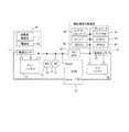
図3は、メインバッテリ41、サブバッテリ42、リレー43a、43bを含むリレーボックス43、および、エンジンコントロールモジュール51を含む詳細な回路構成図である。エンジンコントロールモジュール51は、メインバッテリ41の電圧およびサブバッテリ42の電圧の電圧差に基づいて、リレー43a、43bがオフし続けるオフ固着故障を検出する。
FIG. 3 is a detailed circuit configuration diagram including the
エンジンコントロールモジュール51は、電流センサ71によって検出されるメインバッテリ41の充放電電流と、ハーネスおよびメインバッテリ41の内部抵抗の予測値に基づいて、メインバッテリの電圧を算出する。また、電流センサ72によって検出されるサブバッテリ42の充放電電流と、ハーネスおよびサブバッテリ42の内部抵抗の予測値に基づいて、サブバッテリ42の電圧を算出する。
The
エンジンコントロールモジュール51は、リレー43a、43bがオンし続けるオン固着故障およびオフし続けるオフ固着故障が発生していない正常時には、リレー43a、43bをオンする際に、いずれか一方を交互にオンする。より具体的には、モータジェネレータ21の力行運転中はリレー43a、43bを共にオフにし、モータジェネレータ21の回生運転中はリレー43a、43bのいずれか一方をオンにする。これにより、リレー43aおよび43bを均等に消耗させることができ、リレーを1つだけ設けている場合に比べて、耐久作動回数を延ばすことができる。
The
図4は、メインバッテリ41、サブバッテリ42、リレー43a、43bを含むリレーボックス43、および、エンジンコントロールモジュール51を含む詳細な回路構成図の他の例である。図3に示す回路構成図と異なるのは、電流センサ71、72が設けられている位置である。
FIG. 4 is another example of a detailed circuit configuration diagram including a
図5は、リレーオフ固着故障を診断するタイミングを示す図である。図5では、上から順に、車速V、エンジン2の状態、リレー43a、43bの状態、および、リレーオフ固着診断の状態をそれぞれ示している。図5に示すように、エンジン2の初回始動後の停車時や車両の加速・減速時、アイドルストップからの再始動後など、リレー43a、43bのいずれか一方をオンする指令を出している時に、リレーオフ固着診断を行う。
FIG. 5 is a diagram illustrating timing for diagnosing a relay-off stuck failure. In FIG. 5, the vehicle speed V, the state of the
上述したように、モータジェネレータ21の回生運転時には、リレー43a、43bのいずれか一方をオンにして、メインバッテリ41およびサブバッテリ42に充電電流を供給して充電を行う。この時に、オン指令を出されたリレーにオフ固着故障が生じていると、サブバッテリ42の充電を行うことができずに、サブバッテリ42の放電だけが行われて電圧が低下し続け、充電されるメインバッテリ41と放電し続けるサブバッテリ42との電圧差が広がる。
As described above, during the regenerative operation of the
従って本実施形態では、メインバッテリ41およびサブバッテリ42の電圧差が所定電圧より大きくなると、オン指令が出されたリレーにオフ固着故障が生じていると判断する。より具体的には、後述する第1の条件または第2の条件が成立した場合に、リレーオフ固着故障が生じていると判定する。
Therefore, in this embodiment, when the voltage difference between the
第1の条件が成立した場合とは、下記(a)〜(c)の全ての条件が成立した場合である。
(a)リレー43a、43bのいずれか一方をオンにする指令が出されている。
(b)イグニッションスイッチをオンにしている。
(c)メインバッテリ41およびサブバッテリ42の電圧差が第1の所定電圧(例えば、1.04V)以上、かつ、サブバッテリ42から放電電流が流れている状態で、第1の所定時間(例えば、25.5sec)経過
The case where the first condition is satisfied is a case where all of the following conditions (a) to (c) are satisfied.
(A) A command is issued to turn on one of the
(B) The ignition switch is turned on.
(C) The voltage difference between the
第1の所定電圧は、メインバッテリ41およびサブバッテリ42間に定常電流が流れている定常状態で理論的に発生するバッテリ間の最大電圧差V1に基づいて予め定めておく。より具体的には、第1の所定電圧は、最大電圧差V1よりも高い値に設定する。定常電流が流れている定常状態で理論的に発生するバッテリ間の最大電圧差V1は、次式(1)により表される。ただし、式(1)中のハーネス抵抗値は、メインバッテリ41およびサブバッテリ42間のハーネスの抵抗値である。また、エンジンコントロールモジュール51のバッテリ電圧算出誤差には、電流センサ71、72の電流検出誤差も含まれる。
The first predetermined voltage is determined in advance based on a maximum voltage difference V1 between the batteries that is theoretically generated in a steady state in which a steady current flows between the
最大電圧差V1=リレー43a、43b内部の電圧降下+(ハーネス抵抗値×定常通電電流の最大値)+エンジンコントロールモジュール51のバッテリ電圧算出誤差 …(1)
Maximum voltage difference V1 = voltage drop in
定常電流が流れている定常状態でリレー43a、43bのいずれか一方をオンにする指令が出された場合、指令が出されたリレーがオンとなれば、メインバッテリ41およびサブバッテリ42の電圧差は、上述した最大電圧差V1を超えることはない。すなわち、メインバッテリ41およびサブバッテリ42の電圧差が第1の所定電圧以上となれば、リレーオフ固着故障が生じていると判定できるが、バッテリ間の電圧差が第1の所定電圧以上となる状態が安定的に発生した状態でリレーオフ固着故障が生じていると判定するために、判定時間である第1の所定時間は比較的長い時間(例えば、エンジンコントロールモジュール51で設定可能な最大値)に設定する。
When a command to turn on one of the
一方、第2の条件が成立した場合とは、上記(a)、(b)、および下記(d)の全ての条件が成立した場合である。 On the other hand, the case where the second condition is satisfied is a case where all of the above conditions (a), (b) and the following (d) are satisfied.
(d)メインバッテリ41およびサブバッテリ42の電圧差が第1の所定電圧より高い第2の所定電圧(例えば、1.44V)以上、かつ、サブバッテリ42から放電電流が流れている状態で、第1の所定時間より短い第2の所定時間(例えば、100msec)経過
(D) In a state where the voltage difference between the
第2の所定電圧は、メインバッテリ41およびサブバッテリ42間に過渡電流が流れた状態で理論的に発生するバッテリ間の最大電圧差V2に基づいて予め定めておく。より具体的には、第2の所定電圧は、最大電圧差V2よりも高い値に設定する。過渡電流が流れた状態で理論的に発生するバッテリ間の最大電圧差V2は、次式(2)により表される。
The second predetermined voltage is determined in advance based on the maximum voltage difference V2 between the batteries that is theoretically generated in a state where a transient current flows between the
最大電圧差V2=リレー43a、43b内部の電圧降下+(ハーネス抵抗値×過渡的な通電電流の最大値)+エンジンコントロールモジュール51のバッテリ電圧算出誤差 …(2)
Maximum voltage difference V2 = voltage drop in
メインバッテリ41およびサブバッテリ42間の電圧差が第1の所定電圧より高い第2の所定電圧以上の場合には、迅速にリレーオフ故障が生じていると判定する必要があるため、第2の所定時間はできるだけ短い時間であって、かつ、ノイズ等の微少な電圧変動で誤診断しないような値に設定する。
When the voltage difference between the
図6は、一実施の形態における車両の制御装置によって行われるリレーオフ固着故障診断処理の流れを示すフローチャートである。イグニッションスイッチがオンになると、エンジンコントロールモジュール51は、所定の周期でステップS10の処理を開始する。
FIG. 6 is a flowchart illustrating a flow of a relay-off-fixation failure diagnosis process performed by the vehicle control device according to the embodiment. When the ignition switch is turned on, the
ステップS10では、リレー43a、43bのいずれか一方をオンにする指令が出されているか否かを判定する。リレー43a、43bのいずれか一方をオンにする指令が出されていると判定するとステップS20に進む。
In step S10, it is determined whether or not a command to turn on one of the
ステップS20では、メインバッテリ41およびサブバッテリ42の電圧差を算出する。
In step S20, a voltage difference between the
ステップS30では、ステップS20で算出した電圧差が第2の所定電圧以上、かつ、サブバッテリ42から放電電流が流れているか否かを判定する。バッテリ電圧差が第2の所定電圧以上、かつ、サブバッテリ42から放電電流が流れていると判定するとステップS40に進み、それ以外の場合にはステップS60に進む。 In step S30, it is determined whether or not the voltage difference calculated in step S20 is greater than or equal to a second predetermined voltage and whether or not a discharge current is flowing from the sub-battery 42. If it is determined that the battery voltage difference is equal to or greater than the second predetermined voltage and a discharge current is flowing from the sub-battery 42, the process proceeds to step S40. Otherwise, the process proceeds to step S60.
ステップS40では、カウンタTaに1を加算する。なお、カウンタTaの初期値は0とする。 In step S40, 1 is added to the counter Ta. The initial value of the counter Ta is 0.
ステップS50では、カウンタTaが所定のしきい値Th2より大きいか否かを判定する。所定のしきい値Th2は、ステップS30の判定を肯定してから第2の所定時間が経過したか否かを判定するための値を予め設定しておく。カウンタTaが所定のしきい値Th2以下であると判定するとステップS20に戻り、所定のしきい値Th2より大きい(第2の所定時間経過)と判定するとステップS90に進む。 In step S50, it is determined whether the counter Ta is greater than a predetermined threshold value Th2. The predetermined threshold value Th2 is set in advance as a value for determining whether or not the second predetermined time has elapsed since the determination in step S30 was affirmed. If it is determined that the counter Ta is equal to or smaller than the predetermined threshold value Th2, the process returns to step S20. If it is determined that the counter Ta is greater than the predetermined threshold value Th2 (second predetermined time has elapsed), the process proceeds to step S90.
ステップS60では、ステップS20で算出した電圧差が第1の所定電圧以上、かつ、サブバッテリ42から放電電流が流れているか否かを判定する。バッテリ電圧差が第1の所定電圧以上、かつ、サブバッテリ42から放電電流が流れていると判定するとステップS70に進み、それ以外の場合にはフローチャートの処理を終了する。 In step S60, it is determined whether or not the voltage difference calculated in step S20 is greater than or equal to the first predetermined voltage and whether or not a discharge current is flowing from the sub-battery 42. If it is determined that the battery voltage difference is equal to or greater than the first predetermined voltage and the discharge current is flowing from the sub-battery 42, the process proceeds to step S70. Otherwise, the process of the flowchart is terminated.
ステップS70では、カウンタTbに1を加算する。なお、カウンタTbの初期値は0とする。 In step S70, 1 is added to the counter Tb. Note that the initial value of the counter Tb is 0.
ステップS80では、カウンタTbが所定のしきい値Th1より大きいか否かを判定する。所定のしきい値Th1は、ステップS60の判定を肯定してから第1の所定時間が経過したか否かを判定するための値を予め設定しておく。カウンタTbが所定のしきい値Th1以下であると判定するとステップS20に戻り、所定のしきい値Th1より大きいと判定するとステップS90に進む。 In step S80, it is determined whether or not the counter Tb is greater than a predetermined threshold value Th1. The predetermined threshold value Th1 is set in advance to determine whether or not the first predetermined time has elapsed since the determination in step S60 was affirmed. If it is determined that the counter Tb is equal to or smaller than the predetermined threshold value Th1, the process returns to step S20. If it is determined that the counter Tb is greater than the predetermined threshold value Th1, the process proceeds to step S90.
ステップS90では、オン指令が出されたリレーにオフ固着故障が生じていると判断する。 In step S90, it is determined that an off-fixing failure has occurred in the relay for which the on command has been issued.
以上、一実施の形態における車両の制御装置によれば、エンジンの出力軸に機械的に結合されたモータジェネレータ21と、モータジェネレータ21と電気的に結合されたメインバッテリ41と、車両の電気負荷と電気的に結合されたサブバッテリ42と、メインバッテリ41およびサブバッテリ42を電気的に結合するか否かを自身のオン/オフにより切替可能なリレー43a、43bとを備え、モータジェネレータ21の力行運転中はリレー43a、43bをオフにし、モータジェネレータ21の回生運転中はリレー43aまたは43bをオンにする制御を行い、リレーをオンにする指令が出されている状態で、メインバッテリ41の電圧およびサブバッテリ42の電圧の差が所定電圧より大きくなった場合に、オンにする指令が出されたリレーがオフ固着していると判定する。モータジェネレータ21の回生運転時には、リレー43a、43bのいずれか一方がオンになっていれば、メインバッテリ41およびサブバッテリ42に充電電流が供給されて充電が行われるが、オン指令を出されたリレーにオフ固着故障が生じていると、サブバッテリ42の充電を行うことができずに、サブバッテリ42の放電だけが行われて電圧が低下し続け、メインバッテリ41とサブバッテリ42の電圧差が広がる。従って、リレー43aまたは43bをオンにする指令が出されている状態で、メインバッテリ41の電圧およびサブバッテリ42の電圧の差が所定電圧より大きくなれば、リレーオフ固着故障が生じていることを確実に検出することができる。
As described above, according to the vehicle control apparatus in the embodiment, the
特に、リレーをオンにする指令が出されている状態で、メインバッテリ41の電圧およびサブバッテリ42の電圧の差が第1の所定電圧より大きい状態で第1の所定時間を経過すると、オンにする指令が出されたリレーがオフ固着していると判定する。これにより、リレーのオフ固着故障を精度良く検出することができる。
In particular, when a command to turn on the relay is issued and the difference between the voltage of the
また、リレーをオンにする指令が出されている状態で、メインバッテリ41の電圧およびサブバッテリ42の電圧の差が第1の所定電圧より高い第2の所定電圧より大きい状態で第1の所定時間より短い第2の所定時間を経過すると、オンにする指令が出されたリレーがオフ固着していると判定する。これにより、リレーのオフ固着故障を迅速に検出することができる。
In addition, in a state where a command to turn on the relay is issued, the first predetermined voltage in a state where the difference between the voltage of the
本発明は、上述した一実施の形態に限定されることはなく、本発明の要旨を逸脱しない範囲で様々な変形や応用が可能である。例えば、メインバッテリ41およびサブバッテリ42の電圧は、バッテリの充放電電流およびバッテリの内部抵抗の予測値から算出したが、電圧センサを設けて直接検出するようにしてもよい。
The present invention is not limited to the above-described embodiment, and various modifications and applications are possible without departing from the gist of the present invention. For example, the voltages of the
2…エンジン
21…モータジェネレータ
41…メインバッテリ(第1バッテリ)
42…サブバッテリ(第2バッテリ)
43a、43b…リレー
51…エンジンコントロールモジュール(リレー制御手段、リレー故障診断手段)
2 ...
42 ... Sub battery (second battery)
43a, 43b ... relay 51 ... engine control module (relay control means, relay failure diagnosis means)
Claims (2)
前記モータジェネレータと電気的に結合された第1バッテリと、
車両の電気負荷と電気的に結合された第2バッテリと、
前記第1バッテリおよび前記第2バッテリを電気的に結合するか否かを自身のオン/オフにより切替可能なリレーと、
前記モータジェネレータの力行運転中は前記リレーをオフにして前記第1バッテリおよび前記第2バッテリの電気的結合を切断し、前記モータジェネレータの回生運転中は前記リレーをオンにして前記第1バッテリおよび前記第2バッテリを電気的に結合するリレー制御手段と、
前記リレーをオンにする指令が出されている状態で、前記第1バッテリの電圧および前記第2バッテリの電圧の差が所定電圧より大きくなった場合に、前記リレーがオフ固着していると判定するリレー故障診断手段と、
を備え、
前記リレー故障診断手段は、前記リレーをオンにする指令が出されている状態で、前記第1バッテリの電圧および前記第2バッテリの電圧の差が前記第1の所定電圧より高い第2の所定電圧より大きい状態で前記第1の所定時間より短い第2の所定時間を経過すると、前記リレーがオフ固着していると判定し、
前記第1の所定電圧は、定常電流が流れる定常状態において発生する前記第1バッテリと前記第2バッテリとの間の最大電圧差よりも高く、
前記第2の所定電圧は、前記第1バッテリと前記第2バッテリとの間に過渡電流が流れる状態において発生する前記第1バッテリと前記第2バッテリとの間の最大電圧差よりも高い、ことを特徴とする車両の制御装置。 A motor generator mechanically coupled to the output shaft of the engine;
A first battery electrically coupled to the motor generator;
A second battery electrically coupled to an electrical load of the vehicle;
A relay capable of switching whether or not to electrically couple the first battery and the second battery by ON / OFF of the first battery and the second battery;
During the power running operation of the motor generator, the relay is turned off to disconnect the electrical connection between the first battery and the second battery, and during the regenerative operation of the motor generator, the relay is turned on to turn the first battery and Relay control means for electrically coupling the second battery;
When the command to turn on the relay is issued and the difference between the voltage of the first battery and the voltage of the second battery is greater than a predetermined voltage, it is determined that the relay is fixed off. Relay failure diagnosis means to
Equipped with a,
The relay failure diagnosing means is configured to output a second predetermined voltage in which a difference between the voltage of the first battery and the voltage of the second battery is higher than the first predetermined voltage in a state where a command to turn on the relay is issued. When a second predetermined time shorter than the first predetermined time elapses in a state larger than the voltage, it is determined that the relay is fixed off,
The first predetermined voltage is higher than a maximum voltage difference between the first battery and the second battery that occurs in a steady state in which a steady current flows.
The second predetermined voltage is higher than a maximum voltage difference between the first battery and the second battery that occurs in a state where a transient current flows between the first battery and the second battery. A control device for a vehicle.
前記リレー故障診断手段は、前記リレーをオンにする指令が出されている状態で、前記第1バッテリの電圧および前記第2バッテリの電圧の差が第1の所定電圧より大きい状態で第1の所定時間を経過すると、前記リレーがオフ固着していると判定する、
ことを特徴とする車両の制御装置。 The vehicle control device according to claim 1,
The relay failure diagnosing means is in a state where a command to turn on the relay is issued, and a difference between the voltage of the first battery and the voltage of the second battery is greater than a first predetermined voltage. When a predetermined time has elapsed, it is determined that the relay is fixed off,
A control apparatus for a vehicle.
Priority Applications (1)
| Application Number | Priority Date | Filing Date | Title |
|---|---|---|---|
| JP2012198764A JP6036048B2 (en) | 2012-09-10 | 2012-09-10 | Vehicle control device |
Applications Claiming Priority (1)
| Application Number | Priority Date | Filing Date | Title |
|---|---|---|---|
| JP2012198764A JP6036048B2 (en) | 2012-09-10 | 2012-09-10 | Vehicle control device |
Publications (2)
| Publication Number | Publication Date |
|---|---|
| JP2014051956A JP2014051956A (en) | 2014-03-20 |
| JP6036048B2 true JP6036048B2 (en) | 2016-11-30 |
Family
ID=50610641
Family Applications (1)
| Application Number | Title | Priority Date | Filing Date |
|---|---|---|---|
| JP2012198764A Active JP6036048B2 (en) | 2012-09-10 | 2012-09-10 | Vehicle control device |
Country Status (1)
| Country | Link |
|---|---|
| JP (1) | JP6036048B2 (en) |
Families Citing this family (4)
| Publication number | Priority date | Publication date | Assignee | Title |
|---|---|---|---|---|
| JP6091478B2 (en) | 2014-11-06 | 2017-03-08 | 矢崎総業株式会社 | Switch box |
| JP6749194B2 (en) * | 2016-09-28 | 2020-09-02 | 株式会社Subaru | In-vehicle motor failure diagnosis device |
| JP7070523B2 (en) * | 2019-09-12 | 2022-05-18 | 株式会社デンソー | Energization control device and power supply unit |
| CN115184794B (en) * | 2022-09-13 | 2022-12-13 | 合肥华思系统有限公司 | Relay adhesion detection method and device for multi-cluster battery system |
Family Cites Families (6)
| Publication number | Priority date | Publication date | Assignee | Title |
|---|---|---|---|---|
| JP2006322362A (en) * | 2005-05-18 | 2006-11-30 | Fujitsu Ten Ltd | Automatic engine stop and start controller |
| JP4784339B2 (en) * | 2006-02-28 | 2011-10-05 | トヨタ自動車株式会社 | Power supply control device and vehicle |
| JP5034316B2 (en) * | 2006-05-22 | 2012-09-26 | トヨタ自動車株式会社 | Power supply |
| JP2008082275A (en) * | 2006-09-28 | 2008-04-10 | Mazda Motor Corp | Battery deterioration detecting device |
| JP5038053B2 (en) * | 2007-08-07 | 2012-10-03 | キヤノン株式会社 | Image projection device |
| KR100921061B1 (en) * | 2008-03-27 | 2009-10-08 | 현대자동차주식회사 | Battery charge controlling method of hybrid vehicle |
-
2012
- 2012-09-10 JP JP2012198764A patent/JP6036048B2/en active Active
Also Published As
| Publication number | Publication date |
|---|---|
| JP2014051956A (en) | 2014-03-20 |
Similar Documents
| Publication | Publication Date | Title |
|---|---|---|
| JP5915749B2 (en) | Vehicle control apparatus and vehicle control method | |
| JP5930041B2 (en) | Vehicle control apparatus and vehicle control method | |
| US9458813B2 (en) | Vehicle electric power supply apparatus | |
| JP6036048B2 (en) | Vehicle control device | |
| JP2014189254A (en) | Vehicle | |
| JP5739842B2 (en) | Vehicle drive device | |
| JP2013189134A (en) | Drive device of vehicle | |
| JP6060535B2 (en) | Vehicle drive device | |
| WO2013080746A1 (en) | Engine starting device and starting method | |
| JP6252667B2 (en) | Vehicle drive device | |
| JP6209317B2 (en) | Vehicle drive device | |
| JP2013256174A (en) | Drive device for vehicle | |
| JP6155558B2 (en) | Vehicle drive device | |
| JP6031842B2 (en) | Vehicle drive device | |
| JP6251470B2 (en) | Vehicle drive device | |
| WO2015159876A1 (en) | Control device for vehicles | |
| JP6065047B2 (en) | Vehicle control apparatus and vehicle control method | |
| JP6259556B2 (en) | Vehicle drive device | |
| JP6360653B2 (en) | Vehicle drive device | |
| JP2014001695A (en) | Driving device of vehicle |
Legal Events
| Date | Code | Title | Description |
|---|---|---|---|
| A621 | Written request for application examination |
Free format text: JAPANESE INTERMEDIATE CODE: A621 Effective date: 20150729 |
|
| A977 | Report on retrieval |
Free format text: JAPANESE INTERMEDIATE CODE: A971007 Effective date: 20160526 |
|
| A131 | Notification of reasons for refusal |
Free format text: JAPANESE INTERMEDIATE CODE: A131 Effective date: 20160531 |
|
| A521 | Written amendment |
Free format text: JAPANESE INTERMEDIATE CODE: A523 Effective date: 20160726 |
|
| TRDD | Decision of grant or rejection written | ||
| A01 | Written decision to grant a patent or to grant a registration (utility model) |
Free format text: JAPANESE INTERMEDIATE CODE: A01 Effective date: 20161004 |
|
| A61 | First payment of annual fees (during grant procedure) |
Free format text: JAPANESE INTERMEDIATE CODE: A61 Effective date: 20161017 |
|
| R151 | Written notification of patent or utility model registration |
Ref document number: 6036048 Country of ref document: JP Free format text: JAPANESE INTERMEDIATE CODE: R151 |