JP5034316B2 - Power supply - Google Patents
Power supply Download PDFInfo
- Publication number
- JP5034316B2 JP5034316B2 JP2006141352A JP2006141352A JP5034316B2 JP 5034316 B2 JP5034316 B2 JP 5034316B2 JP 2006141352 A JP2006141352 A JP 2006141352A JP 2006141352 A JP2006141352 A JP 2006141352A JP 5034316 B2 JP5034316 B2 JP 5034316B2
- Authority
- JP
- Japan
- Prior art keywords
- power supply
- power
- cooling medium
- temperature
- cooling
- Prior art date
- Legal status (The legal status is an assumption and is not a legal conclusion. Google has not performed a legal analysis and makes no representation as to the accuracy of the status listed.)
- Active
Links
- 238000001816 cooling Methods 0.000 claims abstract description 263
- 239000003990 capacitor Substances 0.000 claims abstract description 80
- 238000004891 communication Methods 0.000 claims abstract description 25
- 239000002826 coolant Substances 0.000 claims description 101
- 239000000758 substrate Substances 0.000 claims description 31
- 238000011144 upstream manufacturing Methods 0.000 claims description 28
- 238000007599 discharging Methods 0.000 claims description 16
- 238000009423 ventilation Methods 0.000 claims description 14
- 230000004044 response Effects 0.000 claims description 6
- 238000007664 blowing Methods 0.000 abstract description 7
- 238000010586 diagram Methods 0.000 description 10
- 230000001172 regenerating effect Effects 0.000 description 9
- 230000001133 acceleration Effects 0.000 description 8
- 230000007423 decrease Effects 0.000 description 8
- 101000602926 Homo sapiens Nuclear receptor coactivator 1 Proteins 0.000 description 5
- 101000651467 Homo sapiens Proto-oncogene tyrosine-protein kinase Src Proteins 0.000 description 5
- 101000912503 Homo sapiens Tyrosine-protein kinase Fgr Proteins 0.000 description 5
- 102100026150 Tyrosine-protein kinase Fgr Human genes 0.000 description 5
- 101100150275 Caenorhabditis elegans srb-3 gene Proteins 0.000 description 4
- 108091005487 SCARB1 Proteins 0.000 description 4
- 102100037118 Scavenger receptor class B member 1 Human genes 0.000 description 4
- 230000020169 heat generation Effects 0.000 description 4
- 230000007246 mechanism Effects 0.000 description 4
- 238000000034 method Methods 0.000 description 4
- 230000004048 modification Effects 0.000 description 4
- 238000012986 modification Methods 0.000 description 4
- 239000000446 fuel Substances 0.000 description 3
- 230000004043 responsiveness Effects 0.000 description 3
- 101150086935 MRN1 gene Proteins 0.000 description 2
- 239000003638 chemical reducing agent Substances 0.000 description 2
- 238000010248 power generation Methods 0.000 description 2
- 230000005855 radiation Effects 0.000 description 2
- 230000009467 reduction Effects 0.000 description 2
- 230000008929 regeneration Effects 0.000 description 2
- 238000011069 regeneration method Methods 0.000 description 2
- 101100150273 Caenorhabditis elegans srb-1 gene Proteins 0.000 description 1
- 101001055444 Homo sapiens Mediator of RNA polymerase II transcription subunit 20 Proteins 0.000 description 1
- HBBGRARXTFLTSG-UHFFFAOYSA-N Lithium ion Chemical compound [Li+] HBBGRARXTFLTSG-UHFFFAOYSA-N 0.000 description 1
- 102100026165 Mediator of RNA polymerase II transcription subunit 20 Human genes 0.000 description 1
- 230000005540 biological transmission Effects 0.000 description 1
- 230000008859 change Effects 0.000 description 1
- 238000006243 chemical reaction Methods 0.000 description 1
- 238000002485 combustion reaction Methods 0.000 description 1
- 230000006866 deterioration Effects 0.000 description 1
- 230000017525 heat dissipation Effects 0.000 description 1
- 238000009434 installation Methods 0.000 description 1
- 229910001416 lithium ion Inorganic materials 0.000 description 1
- 229910052987 metal hydride Inorganic materials 0.000 description 1
- 229910052759 nickel Inorganic materials 0.000 description 1
- PXHVJJICTQNCMI-UHFFFAOYSA-N nickel Substances [Ni] PXHVJJICTQNCMI-UHFFFAOYSA-N 0.000 description 1
- -1 nickel metal hydride Chemical class 0.000 description 1
- 230000000644 propagated effect Effects 0.000 description 1
- 239000007858 starting material Substances 0.000 description 1
Images


Classifications
-
- H—ELECTRICITY
- H05—ELECTRIC TECHNIQUES NOT OTHERWISE PROVIDED FOR
- H05K—PRINTED CIRCUITS; CASINGS OR CONSTRUCTIONAL DETAILS OF ELECTRIC APPARATUS; MANUFACTURE OF ASSEMBLAGES OF ELECTRICAL COMPONENTS
- H05K7/00—Constructional details common to different types of electric apparatus
- H05K7/20—Modifications to facilitate cooling, ventilating, or heating
- H05K7/2089—Modifications to facilitate cooling, ventilating, or heating for power electronics, e.g. for inverters for controlling motor
- H05K7/20909—Forced ventilation, e.g. on heat dissipaters coupled to components
-
- B—PERFORMING OPERATIONS; TRANSPORTING
- B60—VEHICLES IN GENERAL
- B60L—PROPULSION OF ELECTRICALLY-PROPELLED VEHICLES; SUPPLYING ELECTRIC POWER FOR AUXILIARY EQUIPMENT OF ELECTRICALLY-PROPELLED VEHICLES; ELECTRODYNAMIC BRAKE SYSTEMS FOR VEHICLES IN GENERAL; MAGNETIC SUSPENSION OR LEVITATION FOR VEHICLES; MONITORING OPERATING VARIABLES OF ELECTRICALLY-PROPELLED VEHICLES; ELECTRIC SAFETY DEVICES FOR ELECTRICALLY-PROPELLED VEHICLES
- B60L50/00—Electric propulsion with power supplied within the vehicle
- B60L50/50—Electric propulsion with power supplied within the vehicle using propulsion power supplied by batteries or fuel cells
- B60L50/60—Electric propulsion with power supplied within the vehicle using propulsion power supplied by batteries or fuel cells using power supplied by batteries
- B60L50/64—Constructional details of batteries specially adapted for electric vehicles
-
- H—ELECTRICITY
- H01—ELECTRIC ELEMENTS
- H01M—PROCESSES OR MEANS, e.g. BATTERIES, FOR THE DIRECT CONVERSION OF CHEMICAL ENERGY INTO ELECTRICAL ENERGY
- H01M10/00—Secondary cells; Manufacture thereof
- H01M10/42—Methods or arrangements for servicing or maintenance of secondary cells or secondary half-cells
- H01M10/48—Accumulators combined with arrangements for measuring, testing or indicating the condition of cells, e.g. the level or density of the electrolyte
- H01M10/486—Accumulators combined with arrangements for measuring, testing or indicating the condition of cells, e.g. the level or density of the electrolyte for measuring temperature
-
- H—ELECTRICITY
- H01—ELECTRIC ELEMENTS
- H01M—PROCESSES OR MEANS, e.g. BATTERIES, FOR THE DIRECT CONVERSION OF CHEMICAL ENERGY INTO ELECTRICAL ENERGY
- H01M10/00—Secondary cells; Manufacture thereof
- H01M10/60—Heating or cooling; Temperature control
- H01M10/62—Heating or cooling; Temperature control specially adapted for specific applications
- H01M10/625—Vehicles
-
- H—ELECTRICITY
- H01—ELECTRIC ELEMENTS
- H01M—PROCESSES OR MEANS, e.g. BATTERIES, FOR THE DIRECT CONVERSION OF CHEMICAL ENERGY INTO ELECTRICAL ENERGY
- H01M50/00—Constructional details or processes of manufacture of the non-active parts of electrochemical cells other than fuel cells, e.g. hybrid cells
- H01M50/20—Mountings; Secondary casings or frames; Racks, modules or packs; Suspension devices; Shock absorbers; Transport or carrying devices; Holders
- H01M50/204—Racks, modules or packs for multiple batteries or multiple cells
-
- H—ELECTRICITY
- H01—ELECTRIC ELEMENTS
- H01M—PROCESSES OR MEANS, e.g. BATTERIES, FOR THE DIRECT CONVERSION OF CHEMICAL ENERGY INTO ELECTRICAL ENERGY
- H01M50/00—Constructional details or processes of manufacture of the non-active parts of electrochemical cells other than fuel cells, e.g. hybrid cells
- H01M50/20—Mountings; Secondary casings or frames; Racks, modules or packs; Suspension devices; Shock absorbers; Transport or carrying devices; Holders
- H01M50/249—Mountings; Secondary casings or frames; Racks, modules or packs; Suspension devices; Shock absorbers; Transport or carrying devices; Holders specially adapted for aircraft or vehicles, e.g. cars or trains
-
- B—PERFORMING OPERATIONS; TRANSPORTING
- B60—VEHICLES IN GENERAL
- B60K—ARRANGEMENT OR MOUNTING OF PROPULSION UNITS OR OF TRANSMISSIONS IN VEHICLES; ARRANGEMENT OR MOUNTING OF PLURAL DIVERSE PRIME-MOVERS IN VEHICLES; AUXILIARY DRIVES FOR VEHICLES; INSTRUMENTATION OR DASHBOARDS FOR VEHICLES; ARRANGEMENTS IN CONNECTION WITH COOLING, AIR INTAKE, GAS EXHAUST OR FUEL SUPPLY OF PROPULSION UNITS IN VEHICLES
- B60K1/00—Arrangement or mounting of electrical propulsion units
- B60K1/02—Arrangement or mounting of electrical propulsion units comprising more than one electric motor
-
- B—PERFORMING OPERATIONS; TRANSPORTING
- B60—VEHICLES IN GENERAL
- B60K—ARRANGEMENT OR MOUNTING OF PROPULSION UNITS OR OF TRANSMISSIONS IN VEHICLES; ARRANGEMENT OR MOUNTING OF PLURAL DIVERSE PRIME-MOVERS IN VEHICLES; AUXILIARY DRIVES FOR VEHICLES; INSTRUMENTATION OR DASHBOARDS FOR VEHICLES; ARRANGEMENTS IN CONNECTION WITH COOLING, AIR INTAKE, GAS EXHAUST OR FUEL SUPPLY OF PROPULSION UNITS IN VEHICLES
- B60K1/00—Arrangement or mounting of electrical propulsion units
- B60K2001/003—Arrangement or mounting of electrical propulsion units with means for cooling the electrical propulsion units
- B60K2001/005—Arrangement or mounting of electrical propulsion units with means for cooling the electrical propulsion units the electric storage means
-
- B—PERFORMING OPERATIONS; TRANSPORTING
- B60—VEHICLES IN GENERAL
- B60K—ARRANGEMENT OR MOUNTING OF PROPULSION UNITS OR OF TRANSMISSIONS IN VEHICLES; ARRANGEMENT OR MOUNTING OF PLURAL DIVERSE PRIME-MOVERS IN VEHICLES; AUXILIARY DRIVES FOR VEHICLES; INSTRUMENTATION OR DASHBOARDS FOR VEHICLES; ARRANGEMENTS IN CONNECTION WITH COOLING, AIR INTAKE, GAS EXHAUST OR FUEL SUPPLY OF PROPULSION UNITS IN VEHICLES
- B60K6/00—Arrangement or mounting of plural diverse prime-movers for mutual or common propulsion, e.g. hybrid propulsion systems comprising electric motors and internal combustion engines ; Control systems therefor, i.e. systems controlling two or more prime movers, or controlling one of these prime movers and any of the transmission, drive or drive units Informative references: mechanical gearings with secondary electric drive F16H3/72; arrangements for handling mechanical energy structurally associated with the dynamo-electric machine H02K7/00; machines comprising structurally interrelated motor and generator parts H02K51/00; dynamo-electric machines not otherwise provided for in H02K see H02K99/00
- B60K6/20—Arrangement or mounting of plural diverse prime-movers for mutual or common propulsion, e.g. hybrid propulsion systems comprising electric motors and internal combustion engines ; Control systems therefor, i.e. systems controlling two or more prime movers, or controlling one of these prime movers and any of the transmission, drive or drive units Informative references: mechanical gearings with secondary electric drive F16H3/72; arrangements for handling mechanical energy structurally associated with the dynamo-electric machine H02K7/00; machines comprising structurally interrelated motor and generator parts H02K51/00; dynamo-electric machines not otherwise provided for in H02K see H02K99/00 the prime-movers consisting of electric motors and internal combustion engines, e.g. HEVs
- B60K6/22—Arrangement or mounting of plural diverse prime-movers for mutual or common propulsion, e.g. hybrid propulsion systems comprising electric motors and internal combustion engines ; Control systems therefor, i.e. systems controlling two or more prime movers, or controlling one of these prime movers and any of the transmission, drive or drive units Informative references: mechanical gearings with secondary electric drive F16H3/72; arrangements for handling mechanical energy structurally associated with the dynamo-electric machine H02K7/00; machines comprising structurally interrelated motor and generator parts H02K51/00; dynamo-electric machines not otherwise provided for in H02K see H02K99/00 the prime-movers consisting of electric motors and internal combustion engines, e.g. HEVs characterised by apparatus, components or means specially adapted for HEVs
- B60K6/36—Arrangement or mounting of plural diverse prime-movers for mutual or common propulsion, e.g. hybrid propulsion systems comprising electric motors and internal combustion engines ; Control systems therefor, i.e. systems controlling two or more prime movers, or controlling one of these prime movers and any of the transmission, drive or drive units Informative references: mechanical gearings with secondary electric drive F16H3/72; arrangements for handling mechanical energy structurally associated with the dynamo-electric machine H02K7/00; machines comprising structurally interrelated motor and generator parts H02K51/00; dynamo-electric machines not otherwise provided for in H02K see H02K99/00 the prime-movers consisting of electric motors and internal combustion engines, e.g. HEVs characterised by apparatus, components or means specially adapted for HEVs characterised by the transmission gearings
- B60K6/365—Arrangement or mounting of plural diverse prime-movers for mutual or common propulsion, e.g. hybrid propulsion systems comprising electric motors and internal combustion engines ; Control systems therefor, i.e. systems controlling two or more prime movers, or controlling one of these prime movers and any of the transmission, drive or drive units Informative references: mechanical gearings with secondary electric drive F16H3/72; arrangements for handling mechanical energy structurally associated with the dynamo-electric machine H02K7/00; machines comprising structurally interrelated motor and generator parts H02K51/00; dynamo-electric machines not otherwise provided for in H02K see H02K99/00 the prime-movers consisting of electric motors and internal combustion engines, e.g. HEVs characterised by apparatus, components or means specially adapted for HEVs characterised by the transmission gearings with the gears having orbital motion
-
- B—PERFORMING OPERATIONS; TRANSPORTING
- B60—VEHICLES IN GENERAL
- B60K—ARRANGEMENT OR MOUNTING OF PROPULSION UNITS OR OF TRANSMISSIONS IN VEHICLES; ARRANGEMENT OR MOUNTING OF PLURAL DIVERSE PRIME-MOVERS IN VEHICLES; AUXILIARY DRIVES FOR VEHICLES; INSTRUMENTATION OR DASHBOARDS FOR VEHICLES; ARRANGEMENTS IN CONNECTION WITH COOLING, AIR INTAKE, GAS EXHAUST OR FUEL SUPPLY OF PROPULSION UNITS IN VEHICLES
- B60K6/00—Arrangement or mounting of plural diverse prime-movers for mutual or common propulsion, e.g. hybrid propulsion systems comprising electric motors and internal combustion engines ; Control systems therefor, i.e. systems controlling two or more prime movers, or controlling one of these prime movers and any of the transmission, drive or drive units Informative references: mechanical gearings with secondary electric drive F16H3/72; arrangements for handling mechanical energy structurally associated with the dynamo-electric machine H02K7/00; machines comprising structurally interrelated motor and generator parts H02K51/00; dynamo-electric machines not otherwise provided for in H02K see H02K99/00
- B60K6/20—Arrangement or mounting of plural diverse prime-movers for mutual or common propulsion, e.g. hybrid propulsion systems comprising electric motors and internal combustion engines ; Control systems therefor, i.e. systems controlling two or more prime movers, or controlling one of these prime movers and any of the transmission, drive or drive units Informative references: mechanical gearings with secondary electric drive F16H3/72; arrangements for handling mechanical energy structurally associated with the dynamo-electric machine H02K7/00; machines comprising structurally interrelated motor and generator parts H02K51/00; dynamo-electric machines not otherwise provided for in H02K see H02K99/00 the prime-movers consisting of electric motors and internal combustion engines, e.g. HEVs
- B60K6/42—Arrangement or mounting of plural diverse prime-movers for mutual or common propulsion, e.g. hybrid propulsion systems comprising electric motors and internal combustion engines ; Control systems therefor, i.e. systems controlling two or more prime movers, or controlling one of these prime movers and any of the transmission, drive or drive units Informative references: mechanical gearings with secondary electric drive F16H3/72; arrangements for handling mechanical energy structurally associated with the dynamo-electric machine H02K7/00; machines comprising structurally interrelated motor and generator parts H02K51/00; dynamo-electric machines not otherwise provided for in H02K see H02K99/00 the prime-movers consisting of electric motors and internal combustion engines, e.g. HEVs characterised by the architecture of the hybrid electric vehicle
- B60K6/44—Series-parallel type
- B60K6/445—Differential gearing distribution type
-
- B—PERFORMING OPERATIONS; TRANSPORTING
- B60—VEHICLES IN GENERAL
- B60L—PROPULSION OF ELECTRICALLY-PROPELLED VEHICLES; SUPPLYING ELECTRIC POWER FOR AUXILIARY EQUIPMENT OF ELECTRICALLY-PROPELLED VEHICLES; ELECTRODYNAMIC BRAKE SYSTEMS FOR VEHICLES IN GENERAL; MAGNETIC SUSPENSION OR LEVITATION FOR VEHICLES; MONITORING OPERATING VARIABLES OF ELECTRICALLY-PROPELLED VEHICLES; ELECTRIC SAFETY DEVICES FOR ELECTRICALLY-PROPELLED VEHICLES
- B60L15/00—Methods, circuits, or devices for controlling the traction-motor speed of electrically-propelled vehicles
- B60L15/007—Physical arrangements or structures of drive train converters specially adapted for the propulsion motors of electric vehicles
-
- B—PERFORMING OPERATIONS; TRANSPORTING
- B60—VEHICLES IN GENERAL
- B60L—PROPULSION OF ELECTRICALLY-PROPELLED VEHICLES; SUPPLYING ELECTRIC POWER FOR AUXILIARY EQUIPMENT OF ELECTRICALLY-PROPELLED VEHICLES; ELECTRODYNAMIC BRAKE SYSTEMS FOR VEHICLES IN GENERAL; MAGNETIC SUSPENSION OR LEVITATION FOR VEHICLES; MONITORING OPERATING VARIABLES OF ELECTRICALLY-PROPELLED VEHICLES; ELECTRIC SAFETY DEVICES FOR ELECTRICALLY-PROPELLED VEHICLES
- B60L2240/00—Control parameters of input or output; Target parameters
- B60L2240/10—Vehicle control parameters
- B60L2240/36—Temperature of vehicle components or parts
-
- B—PERFORMING OPERATIONS; TRANSPORTING
- B60—VEHICLES IN GENERAL
- B60L—PROPULSION OF ELECTRICALLY-PROPELLED VEHICLES; SUPPLYING ELECTRIC POWER FOR AUXILIARY EQUIPMENT OF ELECTRICALLY-PROPELLED VEHICLES; ELECTRODYNAMIC BRAKE SYSTEMS FOR VEHICLES IN GENERAL; MAGNETIC SUSPENSION OR LEVITATION FOR VEHICLES; MONITORING OPERATING VARIABLES OF ELECTRICALLY-PROPELLED VEHICLES; ELECTRIC SAFETY DEVICES FOR ELECTRICALLY-PROPELLED VEHICLES
- B60L3/00—Electric devices on electrically-propelled vehicles for safety purposes; Monitoring operating variables, e.g. speed, deceleration or energy consumption
- B60L3/0023—Detecting, eliminating, remedying or compensating for drive train abnormalities, e.g. failures within the drive train
- B60L3/003—Detecting, eliminating, remedying or compensating for drive train abnormalities, e.g. failures within the drive train relating to inverters
-
- B—PERFORMING OPERATIONS; TRANSPORTING
- B60—VEHICLES IN GENERAL
- B60L—PROPULSION OF ELECTRICALLY-PROPELLED VEHICLES; SUPPLYING ELECTRIC POWER FOR AUXILIARY EQUIPMENT OF ELECTRICALLY-PROPELLED VEHICLES; ELECTRODYNAMIC BRAKE SYSTEMS FOR VEHICLES IN GENERAL; MAGNETIC SUSPENSION OR LEVITATION FOR VEHICLES; MONITORING OPERATING VARIABLES OF ELECTRICALLY-PROPELLED VEHICLES; ELECTRIC SAFETY DEVICES FOR ELECTRICALLY-PROPELLED VEHICLES
- B60L3/00—Electric devices on electrically-propelled vehicles for safety purposes; Monitoring operating variables, e.g. speed, deceleration or energy consumption
- B60L3/0023—Detecting, eliminating, remedying or compensating for drive train abnormalities, e.g. failures within the drive train
- B60L3/0046—Detecting, eliminating, remedying or compensating for drive train abnormalities, e.g. failures within the drive train relating to electric energy storage systems, e.g. batteries or capacitors
-
- B—PERFORMING OPERATIONS; TRANSPORTING
- B60—VEHICLES IN GENERAL
- B60L—PROPULSION OF ELECTRICALLY-PROPELLED VEHICLES; SUPPLYING ELECTRIC POWER FOR AUXILIARY EQUIPMENT OF ELECTRICALLY-PROPELLED VEHICLES; ELECTRODYNAMIC BRAKE SYSTEMS FOR VEHICLES IN GENERAL; MAGNETIC SUSPENSION OR LEVITATION FOR VEHICLES; MONITORING OPERATING VARIABLES OF ELECTRICALLY-PROPELLED VEHICLES; ELECTRIC SAFETY DEVICES FOR ELECTRICALLY-PROPELLED VEHICLES
- B60L3/00—Electric devices on electrically-propelled vehicles for safety purposes; Monitoring operating variables, e.g. speed, deceleration or energy consumption
- B60L3/0023—Detecting, eliminating, remedying or compensating for drive train abnormalities, e.g. failures within the drive train
- B60L3/0053—Detecting, eliminating, remedying or compensating for drive train abnormalities, e.g. failures within the drive train relating to fuel cells
-
- B—PERFORMING OPERATIONS; TRANSPORTING
- B60—VEHICLES IN GENERAL
- B60L—PROPULSION OF ELECTRICALLY-PROPELLED VEHICLES; SUPPLYING ELECTRIC POWER FOR AUXILIARY EQUIPMENT OF ELECTRICALLY-PROPELLED VEHICLES; ELECTRODYNAMIC BRAKE SYSTEMS FOR VEHICLES IN GENERAL; MAGNETIC SUSPENSION OR LEVITATION FOR VEHICLES; MONITORING OPERATING VARIABLES OF ELECTRICALLY-PROPELLED VEHICLES; ELECTRIC SAFETY DEVICES FOR ELECTRICALLY-PROPELLED VEHICLES
- B60L58/00—Methods or circuit arrangements for monitoring or controlling batteries or fuel cells, specially adapted for electric vehicles
- B60L58/10—Methods or circuit arrangements for monitoring or controlling batteries or fuel cells, specially adapted for electric vehicles for monitoring or controlling batteries
- B60L58/24—Methods or circuit arrangements for monitoring or controlling batteries or fuel cells, specially adapted for electric vehicles for monitoring or controlling batteries for controlling the temperature of batteries
- B60L58/26—Methods or circuit arrangements for monitoring or controlling batteries or fuel cells, specially adapted for electric vehicles for monitoring or controlling batteries for controlling the temperature of batteries by cooling
-
- B—PERFORMING OPERATIONS; TRANSPORTING
- B60—VEHICLES IN GENERAL
- B60L—PROPULSION OF ELECTRICALLY-PROPELLED VEHICLES; SUPPLYING ELECTRIC POWER FOR AUXILIARY EQUIPMENT OF ELECTRICALLY-PROPELLED VEHICLES; ELECTRODYNAMIC BRAKE SYSTEMS FOR VEHICLES IN GENERAL; MAGNETIC SUSPENSION OR LEVITATION FOR VEHICLES; MONITORING OPERATING VARIABLES OF ELECTRICALLY-PROPELLED VEHICLES; ELECTRIC SAFETY DEVICES FOR ELECTRICALLY-PROPELLED VEHICLES
- B60L58/00—Methods or circuit arrangements for monitoring or controlling batteries or fuel cells, specially adapted for electric vehicles
- B60L58/30—Methods or circuit arrangements for monitoring or controlling batteries or fuel cells, specially adapted for electric vehicles for monitoring or controlling fuel cells
- B60L58/32—Methods or circuit arrangements for monitoring or controlling batteries or fuel cells, specially adapted for electric vehicles for monitoring or controlling fuel cells for controlling the temperature of fuel cells, e.g. by controlling the electric load
- B60L58/33—Methods or circuit arrangements for monitoring or controlling batteries or fuel cells, specially adapted for electric vehicles for monitoring or controlling fuel cells for controlling the temperature of fuel cells, e.g. by controlling the electric load by cooling
-
- B—PERFORMING OPERATIONS; TRANSPORTING
- B60—VEHICLES IN GENERAL
- B60L—PROPULSION OF ELECTRICALLY-PROPELLED VEHICLES; SUPPLYING ELECTRIC POWER FOR AUXILIARY EQUIPMENT OF ELECTRICALLY-PROPELLED VEHICLES; ELECTRODYNAMIC BRAKE SYSTEMS FOR VEHICLES IN GENERAL; MAGNETIC SUSPENSION OR LEVITATION FOR VEHICLES; MONITORING OPERATING VARIABLES OF ELECTRICALLY-PROPELLED VEHICLES; ELECTRIC SAFETY DEVICES FOR ELECTRICALLY-PROPELLED VEHICLES
- B60L58/00—Methods or circuit arrangements for monitoring or controlling batteries or fuel cells, specially adapted for electric vehicles
- B60L58/30—Methods or circuit arrangements for monitoring or controlling batteries or fuel cells, specially adapted for electric vehicles for monitoring or controlling fuel cells
- B60L58/32—Methods or circuit arrangements for monitoring or controlling batteries or fuel cells, specially adapted for electric vehicles for monitoring or controlling fuel cells for controlling the temperature of fuel cells, e.g. by controlling the electric load
- B60L58/34—Methods or circuit arrangements for monitoring or controlling batteries or fuel cells, specially adapted for electric vehicles for monitoring or controlling fuel cells for controlling the temperature of fuel cells, e.g. by controlling the electric load by heating
-
- B—PERFORMING OPERATIONS; TRANSPORTING
- B60—VEHICLES IN GENERAL
- B60Y—INDEXING SCHEME RELATING TO ASPECTS CROSS-CUTTING VEHICLE TECHNOLOGY
- B60Y2200/00—Type of vehicle
- B60Y2200/90—Vehicles comprising electric prime movers
- B60Y2200/91—Electric vehicles
-
- B—PERFORMING OPERATIONS; TRANSPORTING
- B60—VEHICLES IN GENERAL
- B60Y—INDEXING SCHEME RELATING TO ASPECTS CROSS-CUTTING VEHICLE TECHNOLOGY
- B60Y2200/00—Type of vehicle
- B60Y2200/90—Vehicles comprising electric prime movers
- B60Y2200/92—Hybrid vehicles
-
- H—ELECTRICITY
- H01—ELECTRIC ELEMENTS
- H01M—PROCESSES OR MEANS, e.g. BATTERIES, FOR THE DIRECT CONVERSION OF CHEMICAL ENERGY INTO ELECTRICAL ENERGY
- H01M10/00—Secondary cells; Manufacture thereof
- H01M10/60—Heating or cooling; Temperature control
- H01M10/61—Types of temperature control
- H01M10/613—Cooling or keeping cold
-
- H—ELECTRICITY
- H01—ELECTRIC ELEMENTS
- H01M—PROCESSES OR MEANS, e.g. BATTERIES, FOR THE DIRECT CONVERSION OF CHEMICAL ENERGY INTO ELECTRICAL ENERGY
- H01M10/00—Secondary cells; Manufacture thereof
- H01M10/60—Heating or cooling; Temperature control
- H01M10/63—Control systems
- H01M10/633—Control systems characterised by algorithms, flow charts, software details or the like
-
- H—ELECTRICITY
- H01—ELECTRIC ELEMENTS
- H01M—PROCESSES OR MEANS, e.g. BATTERIES, FOR THE DIRECT CONVERSION OF CHEMICAL ENERGY INTO ELECTRICAL ENERGY
- H01M10/00—Secondary cells; Manufacture thereof
- H01M10/60—Heating or cooling; Temperature control
- H01M10/65—Means for temperature control structurally associated with the cells
- H01M10/656—Means for temperature control structurally associated with the cells characterised by the type of heat-exchange fluid
- H01M10/6561—Gases
- H01M10/6563—Gases with forced flow, e.g. by blowers
- H01M10/6565—Gases with forced flow, e.g. by blowers with recirculation or U-turn in the flow path, i.e. back and forth
-
- H—ELECTRICITY
- H01—ELECTRIC ELEMENTS
- H01M—PROCESSES OR MEANS, e.g. BATTERIES, FOR THE DIRECT CONVERSION OF CHEMICAL ENERGY INTO ELECTRICAL ENERGY
- H01M10/00—Secondary cells; Manufacture thereof
- H01M10/60—Heating or cooling; Temperature control
- H01M10/65—Means for temperature control structurally associated with the cells
- H01M10/656—Means for temperature control structurally associated with the cells characterised by the type of heat-exchange fluid
- H01M10/6561—Gases
- H01M10/6566—Means within the gas flow to guide the flow around one or more cells, e.g. manifolds, baffles or other barriers
-
- H—ELECTRICITY
- H01—ELECTRIC ELEMENTS
- H01M—PROCESSES OR MEANS, e.g. BATTERIES, FOR THE DIRECT CONVERSION OF CHEMICAL ENERGY INTO ELECTRICAL ENERGY
- H01M10/00—Secondary cells; Manufacture thereof
- H01M10/60—Heating or cooling; Temperature control
- H01M10/66—Heat-exchange relationships between the cells and other systems, e.g. central heating systems or fuel cells
- H01M10/667—Heat-exchange relationships between the cells and other systems, e.g. central heating systems or fuel cells the system being an electronic component, e.g. a CPU, an inverter or a capacitor
-
- H—ELECTRICITY
- H01—ELECTRIC ELEMENTS
- H01M—PROCESSES OR MEANS, e.g. BATTERIES, FOR THE DIRECT CONVERSION OF CHEMICAL ENERGY INTO ELECTRICAL ENERGY
- H01M16/00—Structural combinations of different types of electrochemical generators
-
- Y—GENERAL TAGGING OF NEW TECHNOLOGICAL DEVELOPMENTS; GENERAL TAGGING OF CROSS-SECTIONAL TECHNOLOGIES SPANNING OVER SEVERAL SECTIONS OF THE IPC; TECHNICAL SUBJECTS COVERED BY FORMER USPC CROSS-REFERENCE ART COLLECTIONS [XRACs] AND DIGESTS
- Y02—TECHNOLOGIES OR APPLICATIONS FOR MITIGATION OR ADAPTATION AGAINST CLIMATE CHANGE
- Y02E—REDUCTION OF GREENHOUSE GAS [GHG] EMISSIONS, RELATED TO ENERGY GENERATION, TRANSMISSION OR DISTRIBUTION
- Y02E60/00—Enabling technologies; Technologies with a potential or indirect contribution to GHG emissions mitigation
- Y02E60/10—Energy storage using batteries
-
- Y—GENERAL TAGGING OF NEW TECHNOLOGICAL DEVELOPMENTS; GENERAL TAGGING OF CROSS-SECTIONAL TECHNOLOGIES SPANNING OVER SEVERAL SECTIONS OF THE IPC; TECHNICAL SUBJECTS COVERED BY FORMER USPC CROSS-REFERENCE ART COLLECTIONS [XRACs] AND DIGESTS
- Y02—TECHNOLOGIES OR APPLICATIONS FOR MITIGATION OR ADAPTATION AGAINST CLIMATE CHANGE
- Y02T—CLIMATE CHANGE MITIGATION TECHNOLOGIES RELATED TO TRANSPORTATION
- Y02T10/00—Road transport of goods or passengers
- Y02T10/60—Other road transportation technologies with climate change mitigation effect
- Y02T10/62—Hybrid vehicles
-
- Y—GENERAL TAGGING OF NEW TECHNOLOGICAL DEVELOPMENTS; GENERAL TAGGING OF CROSS-SECTIONAL TECHNOLOGIES SPANNING OVER SEVERAL SECTIONS OF THE IPC; TECHNICAL SUBJECTS COVERED BY FORMER USPC CROSS-REFERENCE ART COLLECTIONS [XRACs] AND DIGESTS
- Y02—TECHNOLOGIES OR APPLICATIONS FOR MITIGATION OR ADAPTATION AGAINST CLIMATE CHANGE
- Y02T—CLIMATE CHANGE MITIGATION TECHNOLOGIES RELATED TO TRANSPORTATION
- Y02T10/00—Road transport of goods or passengers
- Y02T10/60—Other road transportation technologies with climate change mitigation effect
- Y02T10/64—Electric machine technologies in electromobility
-
- Y—GENERAL TAGGING OF NEW TECHNOLOGICAL DEVELOPMENTS; GENERAL TAGGING OF CROSS-SECTIONAL TECHNOLOGIES SPANNING OVER SEVERAL SECTIONS OF THE IPC; TECHNICAL SUBJECTS COVERED BY FORMER USPC CROSS-REFERENCE ART COLLECTIONS [XRACs] AND DIGESTS
- Y02—TECHNOLOGIES OR APPLICATIONS FOR MITIGATION OR ADAPTATION AGAINST CLIMATE CHANGE
- Y02T—CLIMATE CHANGE MITIGATION TECHNOLOGIES RELATED TO TRANSPORTATION
- Y02T10/00—Road transport of goods or passengers
- Y02T10/60—Other road transportation technologies with climate change mitigation effect
- Y02T10/70—Energy storage systems for electromobility, e.g. batteries
-
- Y—GENERAL TAGGING OF NEW TECHNOLOGICAL DEVELOPMENTS; GENERAL TAGGING OF CROSS-SECTIONAL TECHNOLOGIES SPANNING OVER SEVERAL SECTIONS OF THE IPC; TECHNICAL SUBJECTS COVERED BY FORMER USPC CROSS-REFERENCE ART COLLECTIONS [XRACs] AND DIGESTS
- Y02—TECHNOLOGIES OR APPLICATIONS FOR MITIGATION OR ADAPTATION AGAINST CLIMATE CHANGE
- Y02T—CLIMATE CHANGE MITIGATION TECHNOLOGIES RELATED TO TRANSPORTATION
- Y02T90/00—Enabling technologies or technologies with a potential or indirect contribution to GHG emissions mitigation
- Y02T90/10—Technologies relating to charging of electric vehicles
- Y02T90/16—Information or communication technologies improving the operation of electric vehicles
-
- Y—GENERAL TAGGING OF NEW TECHNOLOGICAL DEVELOPMENTS; GENERAL TAGGING OF CROSS-SECTIONAL TECHNOLOGIES SPANNING OVER SEVERAL SECTIONS OF THE IPC; TECHNICAL SUBJECTS COVERED BY FORMER USPC CROSS-REFERENCE ART COLLECTIONS [XRACs] AND DIGESTS
- Y02—TECHNOLOGIES OR APPLICATIONS FOR MITIGATION OR ADAPTATION AGAINST CLIMATE CHANGE
- Y02T—CLIMATE CHANGE MITIGATION TECHNOLOGIES RELATED TO TRANSPORTATION
- Y02T90/00—Enabling technologies or technologies with a potential or indirect contribution to GHG emissions mitigation
- Y02T90/40—Application of hydrogen technology to transportation, e.g. using fuel cells
Abstract
Description
この発明は、電源装置に関し、特に、二次電池とキャパシタとから電力供給可能な電源装置に関する。 The present invention relates to a power supply device, and more particularly to a power supply device capable of supplying power from a secondary battery and a capacitor.
最近、環境に配慮した自動車として、ハイブリッド自動車(Hybrid Vehicle)および電気自動車(Electric Vehicle)が注目されている。ハイブリッド自動車は、従来のエンジンに加え、直流電源とインバータとインバータによって駆動されるモータとを動力源とする自動車である。つまり、エンジンを駆動することにより動力源を得るとともに、直流電源からの直流電圧をインバータによって交流電圧に変換し、その変換した交流電圧によりモータを回転することによって動力源を得るものである。 Recently, hybrid vehicles and electric vehicles have attracted attention as environmentally friendly vehicles. A hybrid vehicle is a vehicle that uses a DC power source, an inverter, and a motor driven by the inverter as a power source in addition to a conventional engine. In other words, a power source is obtained by driving the engine, a DC voltage from a DC power source is converted into an AC voltage by an inverter, and a motor is rotated by the converted AC voltage to obtain a power source.
また、電気自動車は、直流電源とインバータとインバータによって駆動されるモータとを動力源とする自動車である。 An electric vehicle is a vehicle that uses a DC power source, an inverter, and a motor driven by the inverter as a power source.
このようなハイブリッド自動車または電気自動車においては、車両を適切に走行させつつエネルギー効率を向上させるためには、そのモータに対する負荷に応じた電力を供給し、回生時は効率良くエネルギーを回収することが求められる。 In such a hybrid vehicle or electric vehicle, in order to improve energy efficiency while driving the vehicle appropriately, power corresponding to the load on the motor is supplied and energy can be efficiently recovered during regeneration. Desired.
このような要求に対応するために、たとえば特許文献1には、二次電池とキャパシタとを並列に接続した蓄電装置をモータの電力供給源として搭載するハイブリッド型車両が開示される。 In order to meet such a demand, for example, Patent Document 1 discloses a hybrid vehicle in which a power storage device in which a secondary battery and a capacitor are connected in parallel is mounted as a power supply source of a motor.
これによれば、蓄電部は、二次電池と電気二重層キャパシタとを並列に接続した電源となっている。コントローラは、車両の負荷変動が小さい状態である定速走行時などにおいて、エンジンの動力によって発電モータを動作させて発電を行ない、その発電した電力で蓄電部を充電する。一方、コントローラは、駆動モータの動力による車両駆動や車両の補機の駆動時などにおいて蓄電部を放電する。 According to this, the power storage unit is a power source in which the secondary battery and the electric double layer capacitor are connected in parallel. The controller operates the power generation motor with the power of the engine to generate electric power when the vehicle is running at a constant speed where the load fluctuation is small, and charges the power storage unit with the generated electric power. On the other hand, the controller discharges the power storage unit when the vehicle is driven by the power of the drive motor or when the auxiliary machine of the vehicle is driven.
ところで、二次電池をモータの電力供給源として搭載した車両においては、通常、充放電時において二次電池内部で発生する熱による電池温度の上昇を抑えるために、冷却装置が搭載される(たとえば特許文献2,3参照)。
これによれば、バッテリセルを複数個収納したバッテリボックスには、冷却ファンを駆動することにより冷却風が供給される。そして、供給された冷却風がバッテリセル間に設けられた間隙を通流することによりバッテリセルが冷却される。 According to this, cooling air is supplied to the battery box containing a plurality of battery cells by driving the cooling fan. Then, the supplied cooling air flows through a gap provided between the battery cells, thereby cooling the battery cells.
上記の特許文献1のようにモータの電力供給源として二次電池とキャパシタとを備える車両においては、二次電池と同様に、キャパシタも充放電によって内部発熱が生じる。したがって、キャパシタに対しても冷却装置が必要となる。 In a vehicle including a secondary battery and a capacitor as a power supply source of a motor as in Patent Document 1 described above, the capacitor also generates internal heat due to charging / discharging, like the secondary battery. Therefore, a cooling device is also required for the capacitor.
ここで、二次電池とキャパシタとでは、内部抵抗の大小や化学反応の有無などに起因して、充放電時における発熱量に違いが生じる。そのため、二次電池およびキャパシタに別個に冷却装置を設け、それぞれの温度に基づいて冷却ファンから供給する冷却風量を個別に制御する構成が検討されている。 Here, there is a difference in the amount of heat generated during charging / discharging between the secondary battery and the capacitor due to the size of the internal resistance or the presence or absence of a chemical reaction. Therefore, a configuration has been studied in which a cooling device is separately provided for the secondary battery and the capacitor, and the amount of cooling air supplied from the cooling fan is individually controlled based on the respective temperatures.
しかしながら、このような構成は、冷却ファンを複数個搭載する必要があるため、冷却装置全体を大型化することになり、搭載スペースの制約が厳しい車両の搭載には適さない場合がある。また、複数の冷却ファンの各々について冷却風量の制御が行なわれるため、制御が複雑化するという問題点が生じる。 However, such a configuration requires a plurality of cooling fans to be mounted, which increases the size of the entire cooling device, and may not be suitable for mounting on a vehicle with severe mounting space restrictions. Further, since the cooling air volume is controlled for each of the plurality of cooling fans, there arises a problem that the control becomes complicated.
さらには、二次電池およびキャパシタは充放電可能電力を維持するのに適した温度範囲を有するため、これらを当該温度範囲内となるように調整できれば、モータに対する電力供給の応答性のさらなる向上が期待される。 Furthermore, since the secondary battery and the capacitor have a temperature range suitable for maintaining chargeable / dischargeable power, if these can be adjusted so as to be within the temperature range, the responsiveness of power supply to the motor can be further improved. Be expected.
それゆえ、この発明は、かかる課題を解決するためになされたものであり、その目的は、小型化され簡素な構成の冷却装置を備えた電源装置を提供することである。 Therefore, the present invention has been made to solve such a problem, and an object of the present invention is to provide a power supply device including a cooling device that is downsized and has a simple configuration.
また、この発明の別の目的は、簡素な構成で温度調整が可能な電源装置を提供することである。 Another object of the present invention is to provide a power supply device capable of adjusting the temperature with a simple configuration.
この発明によれば、電源装置は、負荷へ電力を供給可能に設けられ、負荷の駆動に伴なう充放電による発熱量が相対的に大きい第1電源と、負荷に対して第1電源と並列に接続され、負荷の駆動に伴なう充放電による発熱量が相対的に小さい第2電源と、第1電源および第2電源を冷却する冷却装置とを備える。冷却装置は、冷却媒体を第2電源の上流部に供給する冷却媒体供給部と、冷却媒体供給部により供給された冷却媒体を、第2電源を経由して第1電源に通流させるように形成された冷却媒体流路とを含む。 According to the present invention, the power supply apparatus is provided so as to be able to supply power to the load, and the first power supply that generates a relatively large amount of heat generated by charging and discharging as the load is driven, and the first power supply to the load. A second power supply connected in parallel and having a relatively small amount of heat generated by charging and discharging as the load is driven is provided, and a cooling device for cooling the first power supply and the second power supply. The cooling device supplies a cooling medium to an upstream portion of the second power supply, and causes the cooling medium supplied by the cooling medium supply section to flow to the first power supply via the second power supply. And a formed coolant flow path.
上記の電源装置によれば、低温側の第2電源を経由して高温側の第1電源に冷却媒体を通流させることにより、第1電源と第2電源とを共通の冷却装置を用いて冷却することができる。この結果、電源装置全体をコンパクトな構成とすることができる。 According to the power supply device described above, the first power supply and the second power supply are used by using the common cooling device by passing the cooling medium through the low temperature side second power supply to the high temperature side first power supply. Can be cooled. As a result, the entire power supply device can be made compact.
好ましくは、第1電源は、複数個の第1電源セルが第1の主表面に搭載される第1の基板と、第1の基板を収容し、冷却媒体流路を通流する冷却媒体を電源装置外部へ排出するための第1連通路が設けられた第1の筐体とを含む。第2電源は、複数個の第2電源セルが第1の主表面に搭載される第2の基板と、第2の基板を収容し、冷却媒体を冷却媒体供給部から冷却媒体流路に導入するための第2連通路が設けられた第2の筐体とを含む。第1連通路と第2連通路とは、第3連通路により連通可能に繋がれ、第2の筐体は、第1の基板の第2の主表面と熱伝導可能なように第1の筐体に接触して配置される。 Preferably, the first power source includes a first substrate on which a plurality of first power cells are mounted on the first main surface, and a cooling medium that houses the first substrate and flows through the cooling medium flow path. And a first housing provided with a first communication path for discharging to the outside of the power supply device. The second power source accommodates a second substrate on which a plurality of second power cells are mounted on the first main surface and the second substrate, and introduces a cooling medium from the cooling medium supply unit to the cooling medium flow path. And a second housing provided with a second communication path. The first communication path and the second communication path are connected so as to be able to communicate with each other through the third communication path, and the second casing is configured to be capable of conducting heat with the second main surface of the first substrate. Arranged in contact with the housing.
上記の電源装置によれば、低温側の第2電源を経由して高温側の第1電源に冷却媒体を通流させるとともに、第1電源と第2電源との筐体間で熱交換を行なわせることにより、冷却装置を共通化でき、かつ、冷却効率を高めることができる。 According to the above power supply device, the cooling medium is passed through the first power supply on the high temperature side via the second power supply on the low temperature side, and heat exchange is performed between the housings of the first power supply and the second power supply. As a result, the cooling device can be shared and the cooling efficiency can be increased.
好ましくは、第3連通路は、第1の筐体と第2の筐体との接合面上に形成された複数の通風孔からなる。複数の通風孔は、冷却媒体供給部との間の距離が長くなるに従って開口面積が大きくなるように形成される。 Preferably, the third communication path includes a plurality of ventilation holes formed on the joint surface between the first casing and the second casing. The plurality of ventilation holes are formed so that the opening area increases as the distance from the cooling medium supply unit increases.
上記の電源装置によれば、第1電源に供給される冷却媒体の供給量が筐体内部で不均一になるのが解消される。したがって、第1電源を均等に冷却することができ、冷却効率を一段と高めることができる。 According to the above power supply device, it is possible to eliminate the uneven supply amount of the cooling medium supplied to the first power supply inside the housing. Therefore, the first power source can be evenly cooled, and the cooling efficiency can be further enhanced.
この発明の別の局面によれば、負荷へ電力を供給可能に設けられ、負荷の駆動に伴なう充放電による発熱量が相対的に大きい第1電源と、負荷に対して第1電源と並列に接続され、負荷の駆動に伴なう充放電による発熱量が相対的に小さい第2電源と、第1電源および第2電源の温度調整を行なう温度調整装置とを備える。温度調整装置は、冷却媒体を第1電源の上流部に供給する冷却媒体供給部と、冷却媒体供給部により供給された冷却媒体を、第1電源を経由して第2電源に通流させるように形成された冷却媒体流路とを含む。 According to another aspect of the present invention, a first power source provided so as to be able to supply power to a load and having a relatively large amount of heat generated by charging and discharging accompanying driving of the load, and a first power source with respect to the load A second power source connected in parallel and having a relatively small amount of heat generated by charging / discharging accompanying driving of the load, and a temperature adjusting device for adjusting the temperature of the first power source and the second power source are provided. The temperature adjusting device causes the cooling medium supply unit that supplies the cooling medium to the upstream portion of the first power source and the cooling medium supplied by the cooling medium supply unit to flow to the second power source via the first power source. And a cooling medium flow path formed on the surface.
上記の電源装置によれば、低温環境下では、高温側の第1電源から回収した熱エネルギーを用いて低温側の第2電源を昇温できるため、電力供給源の充放電可能電力の低下を抑制することができる。 According to the above power supply device, in a low temperature environment, the temperature of the second power source on the low temperature side can be raised using the thermal energy recovered from the first power source on the high temperature side, so that the chargeable / dischargeable power of the power supply source is reduced. Can be suppressed.
好ましくは、第1電源は、複数個の第1電源セルが第1の主表面に搭載される第1の基板と、第1の基板を収容し、冷却媒体流路を通流する冷却媒体を電源装置外部へ排出するための第1連通路が設けられた第1の筐体とを含む。第2電源は、複数個の第2電源セルが第1の主表面に搭載される第2の基板と、第2の基板を収容し、冷却媒体を冷却媒体供給部から冷却媒体流路に導入するための第2連通路が設けられた第2の筐体とを含む。第1連通路と第2連通路とは、第3連通路により連通可能に繋がれ、第1の筐体は、第2の基板の第2の主表面と熱伝導可能なように第2の筐体に接触して配置される。 Preferably, the first power source includes a first substrate on which a plurality of first power cells are mounted on the first main surface, and a cooling medium that houses the first substrate and flows through the cooling medium flow path. And a first housing provided with a first communication path for discharging to the outside of the power supply device. The second power source accommodates a second substrate on which a plurality of second power cells are mounted on the first main surface and the second substrate, and introduces a cooling medium from the cooling medium supply unit to the cooling medium flow path. And a second housing provided with a second communication path. The first communication path and the second communication path are connected by a third communication path so as to be able to communicate with each other, and the first housing is configured to be capable of conducting heat with the second main surface of the second substrate. Arranged in contact with the housing.
上記の電源装置によれば、高温側の第1電源を経由して低温側の第2電源に冷却媒体を通流させるとともに、第1電源と第2電源との筐体間で熱交換を行なわせることにより、第2電源を効率良く昇温することができる。 According to the above power supply device, the cooling medium is passed through the first power supply on the high temperature side to the second power supply on the low temperature side, and heat is exchanged between the housings of the first power supply and the second power supply. As a result, the temperature of the second power source can be raised efficiently.
好ましくは、第3連通路は、第1の筐体と第2の筐体との接合面上に形成された複数の通風孔からなる。複数の通風孔は、冷却供給部との間の距離が長くなるに従って開口面積が大きくなるように形成される。 Preferably, the third communication path includes a plurality of ventilation holes formed on the joint surface between the first casing and the second casing. The plurality of ventilation holes are formed such that the opening area increases as the distance from the cooling supply unit increases.
上記の電源装置によれば、第2電源に供給される冷却媒体の供給量が筐体内部で不均一になるのが解消される。したがって、第2電源を均等に昇温することができ、昇温効率を一段と高めることができる。 According to the power supply device described above, the supply amount of the cooling medium supplied to the second power supply is eliminated from becoming uneven within the housing. Therefore, the temperature of the second power source can be raised uniformly, and the temperature raising efficiency can be further increased.
この発明の別の局面によれば、電源装置は、負荷へ電力を供給可能に設けられた第1電源と、負荷に対して第1電源と並列に接続された第2電源と、第1電源および第2電源の温度調整を行なう温度調整装置とを備える。温度調整装置は、第1電源と第2電源とが冷却媒体の通流方向に沿って直列に配置されるように形成された冷却媒体流路と、冷却媒体流路の第1電源側の一方端に設けられ、第1電源の上流部に冷却媒体を供給する第1の冷却媒体供給部と、冷却媒体流路の第2電源側の他方端に設けられ、第2電源の上流部に冷却媒体を供給する第2の冷却媒体供給部と、電源装置の雰囲気温度、電源の温度および蓄電装置の温度に基づいて、第1の冷却媒体供給部および第2の冷却媒体供給部のいずれか一方を選択的に作動する選択手段とを含む。 According to another aspect of the present invention, a power supply device includes a first power supply provided to be able to supply power to a load, a second power supply connected in parallel with the first power supply to the load, and a first power supply. And a temperature adjusting device for adjusting the temperature of the second power source. The temperature adjusting device includes a cooling medium channel formed such that the first power source and the second power source are arranged in series along the flow direction of the cooling medium, and one of the cooling medium channel on the first power source side The first cooling medium supply unit that is provided at the end and supplies the cooling medium to the upstream portion of the first power supply and the other end of the cooling medium flow path on the second power supply side and is cooled at the upstream portion of the second power supply One of the first cooling medium supply unit and the second cooling medium supply unit based on the ambient temperature of the power supply device, the temperature of the power supply, and the temperature of the power storage device based on the second cooling medium supply unit that supplies the medium Selecting means for selectively actuating.
上記の電源装置によれば、第1電源および第2電源を共通して通流する冷却媒体を用いて冷却および昇温を選択的に行なうことができるため、第1電源および第2電源の温度調整装置を簡素に構築することができる。 According to the power supply device described above, since the cooling and the temperature increase can be selectively performed using the cooling medium that flows in common through the first power supply and the second power supply, the temperatures of the first power supply and the second power supply can be achieved. The adjustment device can be constructed simply.
好ましくは、選択手段は、電源装置の雰囲気温度が所定の閾値よりも高いとき、第1電源の温度が第2電源の温度よりも高いことに応じて、第1の冷却供給部を選択する一方で、第2電源の温度が第1電源の温度よりも高いことに応じて、第2の冷却媒体供給部を選択する。 Preferably, the selection unit selects the first cooling supply unit according to the fact that the temperature of the first power source is higher than the temperature of the second power source when the ambient temperature of the power source device is higher than a predetermined threshold value. Thus, the second cooling medium supply unit is selected in response to the temperature of the second power source being higher than the temperature of the first power source.
上記の電源装置によれば、電源装置が常温のときには、低温側から高温側に冷却媒体が通流するように冷却媒体流路を選択することにより、共通の冷却媒体を用いて第1電源および第2電源を冷却することができる。 According to the above power supply device, when the power supply device is at room temperature, the first power supply and the common power supply medium are selected by selecting the cooling medium flow path so that the cooling medium flows from the low temperature side to the high temperature side. The second power source can be cooled.
好ましくは、選択手段は、電源装置の雰囲気温度が所定の閾値以下のとき、第1電源の温度が第2電源の温度よりも高いことに応じて、第2の冷却媒体供給部を選択する一方で、第2電源の温度が第1電源の温度よりも高いことに応じて、第1の冷却媒体供給部を選択する。 Preferably, the selection unit selects the second cooling medium supply unit according to the fact that the temperature of the first power supply is higher than the temperature of the second power supply when the ambient temperature of the power supply apparatus is equal to or lower than a predetermined threshold value. Thus, the first cooling medium supply unit is selected in response to the temperature of the second power source being higher than the temperature of the first power source.
上記の電源装置によれば、電源装置は低温のときには、高温側から低温側に冷却媒体が通流するように冷却媒体流路を選択することにより、一方から回収した熱エネルギーを用いて他方を昇温できる。 According to the power supply device described above, when the power supply device is at a low temperature, the cooling medium flow path is selected so that the cooling medium flows from the high temperature side to the low temperature side, and the other is used by using the thermal energy recovered from one side. The temperature can be raised.
好ましくは、電源装置は、冷却媒体流路への冷却媒体の供給量を制御する制御手段をさらに備える。制御手段は、第1電源の温度が第2電源の温度よりも高いとき、第1電源の温度に基づいて冷却媒体の供給量を決定し、かつ、第2電源の温度が第1電源の温度よりも高いとき、第2電源の温度に基づいて冷却媒体の供給量を決定する。 Preferably, the power supply device further includes control means for controlling a supply amount of the cooling medium to the cooling medium flow path. The control means determines the supply amount of the cooling medium based on the temperature of the first power source when the temperature of the first power source is higher than the temperature of the second power source, and the temperature of the second power source is the temperature of the first power source. Is higher, the supply amount of the cooling medium is determined based on the temperature of the second power source.
上記の電源装置によれば、高温側の温度に基づいて冷却媒体の供給量を決定することにより、冷却媒体を共用することによっても温度調整を効率的に行なうことができる。 According to the power supply device described above, by determining the supply amount of the cooling medium based on the temperature on the high temperature side, the temperature adjustment can also be efficiently performed by sharing the cooling medium.
好ましくは、第1電源は、二次電池であり、第2電源は、キャパシタである。
上記の電源装置によれば、二次電池およびキャパシタの充放電可能電力の低下が抑えられるため、これらの併用による負荷の駆動応答性を保つことができる。
Preferably, the first power source is a secondary battery, and the second power source is a capacitor.
According to the power supply device described above, since the reduction in chargeable / dischargeable power of the secondary battery and the capacitor can be suppressed, the drive responsiveness of the load due to the combined use thereof can be maintained.
好ましくは、負荷は、車両駆動用のモータであり、電源装置は、車両にモータの電力源として搭載される。 Preferably, the load is a motor for driving the vehicle, and the power supply device is mounted on the vehicle as a power source of the motor.
上記の電源装置によれば、電源装置の小型化が可能であるため、搭載スペースの制約が厳しい車両への搭載に適している。 According to the power supply device described above, the power supply device can be reduced in size, and thus is suitable for mounting on a vehicle with a severe mounting space restriction.
この発明によれば、小型化され簡素な構成の冷却装置を備えた電源装置を実現することができる。 According to the present invention, it is possible to realize a power supply device that includes a cooling device that is downsized and has a simple configuration.
また、簡素な構成で、電源装置を構成する複数の電源の温度調整を行なうことができる。 In addition, the temperature of a plurality of power supplies constituting the power supply device can be adjusted with a simple configuration.
以下、この発明の実施の形態について図面を参照して詳しく説明する。なお、図中同一符号は同一または相当部分を示す。 Hereinafter, embodiments of the present invention will be described in detail with reference to the drawings. In the drawings, the same reference numerals indicate the same or corresponding parts.
[実施の形態1]
図1は、この発明の実施の形態1による電源装置が適用されるモータ駆動装置の概略ブロック図である。
[Embodiment 1]
FIG. 1 is a schematic block diagram of a motor drive device to which a power supply device according to Embodiment 1 of the present invention is applied.
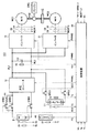
図1を参照して、モータ駆動装置100は、バッテリBと、昇圧コンバータ12と、蓄電装置C1と、コンデンサC2と、インバータ14,31と、電圧センサ10,11,13と、電流センサ24,28と、温度センサ20〜22と、冷却装置40と、システムリレーSRB1〜SRB3,SRC1,SRC2と、抵抗R1と、制御装置30とを備える。
Referring to FIG. 1,
エンジンENGは、ガソリンなどの燃料の燃焼エネルギーを源として駆動力を発生する。エンジンENGの発生する駆動力は、図1の太斜線で示すように、動力分割機構PSDにより、2つの経路に分割される。一方は、図示しない減速機を介して車輪を駆動する駆動軸に伝達する経路である。もう一方は、モータジェネレータMG1へ伝達する経路である。 The engine ENG generates driving force using combustion energy of fuel such as gasoline as a source. The driving force generated by the engine ENG is divided into two paths by the power split mechanism PSD as shown by the thick oblique lines in FIG. One is a path that transmits to a drive shaft that drives a wheel via a reduction gear (not shown). The other is a path for transmission to motor generator MG1.
モータジェネレータMG1,MG2は、発電機としても電動機としても機能し得るが、以下に示すように、モータジェネレータMG1は、主として発電機として動作し、モータジェネレータMG2は、主として電動機として動作する。 Although motor generators MG1 and MG2 can function as both a generator and an electric motor, as will be described below, motor generator MG1 mainly operates as a generator, and motor generator MG2 mainly operates as an electric motor.
詳細には、モータジェネレータMG1は、三相交流回転機であり、加速時において、エンジンENGを始動する始動機として用いられる。このとき、モータジェネレータMG1は、バッテリBおよび/または蓄電装置C1からの電力の供給を受けて電動機として駆動し、エンジンENGをクランキングして始動する。 Specifically, motor generator MG1 is a three-phase AC rotating machine, and is used as a starter that starts engine ENG during acceleration. At this time, motor generator MG1 receives the supply of electric power from battery B and / or power storage device C1, drives it as an electric motor, cranks engine ENG, and starts it.
さらに、エンジンENGの始動後において、モータジェネレータMG1は、動力分割機構PSDを介して伝達されたエンジンENGの駆動力によって回転されて発電する。 Further, after engine ENG is started, motor generator MG1 is rotated by the driving force of engine ENG transmitted through power split mechanism PSD to generate electric power.
モータジェネレータMG1の発電した電力は、車両の運転状態や蓄電装置C1の蓄電エネルギーおよびバッテリBの充電量によって使い分けられる。たとえば、通常走行時や急加速時においては、モータジェネレータMG1の発電した電力は、そのままモータジェネレータMG2を駆動させる電力となる。一方、バッテリBの充電量または蓄電装置C1の蓄電エネルギーが所定の値よりも低いときには、モータジェネレータMG1の発電した電力は、インバータ14によって交流電力から直流電力に変換されて、バッテリBまたは蓄電装置C1に蓄えられる。
The electric power generated by motor generator MG1 is selectively used depending on the driving state of the vehicle, the energy stored in power storage device C1, and the amount of charge of battery B. For example, during normal traveling or sudden acceleration, the electric power generated by motor generator MG1 becomes electric power for driving motor generator MG2 as it is. On the other hand, when the charge amount of battery B or the stored energy of power storage device C1 is lower than a predetermined value, the power generated by motor generator MG1 is converted from AC power to DC power by
モータジェネレータMG2は、三相交流回転機であり、バッテリBおよび蓄電装置C1に蓄えられた電力とモータジェネレータMG1が発電した電力との少なくともいずれか一方によって駆動される。モータジェネレータMG2の駆動力は、減速機を介して車輪の駆動軸に伝達される。これにより、モータジェネレータMG2は、エンジンENGをアシストして車両を走行させたり、自己の駆動力のみによって車両を走行させたりする。 Motor generator MG2 is a three-phase AC rotating machine, and is driven by at least one of the electric power stored in battery B and power storage device C1 and the electric power generated by motor generator MG1. The driving force of motor generator MG2 is transmitted to the drive shaft of the wheel via the speed reducer. Thus, motor generator MG2 assists engine ENG to cause the vehicle to travel, or causes the vehicle to travel only by its own driving force.
また、車両の回生制動時には、モータジェネレータMG2は、減速機を介して車輪により回転されて発電機として動作する。このとき、モータジェネレータMG2により発電された回生電力は、インバータ31を介してバッテリBおよび蓄電装置C1に充電される。
Further, at the time of regenerative braking of the vehicle, motor generator MG2 is rotated by a wheel via a speed reducer and operates as a generator. At this time, the regenerative power generated by motor generator MG2 is charged to battery B and power storage device C1 via
バッテリBは、ニッケル水素電池またはリチウムイオン電池などの二次電池から成る。他にも、バッテリBは、燃料電池であってもよい。電圧センサ10は、バッテリBから出力される直流電圧Vbを検出し、その検出した直流電圧Vbを制御装置30へ出力する。温度センサ20は、バッテリBの温度(以下、バッテリ温度とも称する)Tbを検出し、その検出したバッテリ温度Tbを制御装置30へ出力する。
The battery B is a secondary battery such as a nickel metal hydride battery or a lithium ion battery. In addition, the battery B may be a fuel cell.
システムリレーSRB1および抵抗R1は、バッテリBの正極と昇圧コンバータ12との間に直列に接続される。システムリレーSRB2は、バッテリBの正極と昇圧コンバータ12との間に、システムリレーSRB1および抵抗R1に並列に接続される。システムリレーSRB3は、バッテリBの負極と昇圧コンバータ12との間に接続される。
System relay SRB 1 and resistor R 1 are connected in series between the positive electrode of battery B and boost
システムリレーSRB1〜SRB3は、制御装置30からの信号SEBによりオン/オフされる。より具体的には、システムリレーSRB1〜SRB3は、制御装置30からのH(論理ハイ)レベルの信号SEBによりオンされ、制御装置30からのL(論理ロー)レベルの信号SEBによりオフされる。
System relays SRB1 to SRB3 are turned on / off by a signal SEB from
昇圧コンバータ12は、バッテリBから供給された直流電圧Vbを任意のレベルを有する昇圧電圧に昇圧してコンデンサC2へ供給する。より具体的には、昇圧コンバータ12は、制御装置30から信号PWMCを受けると、信号PWMCに応じて昇圧した直流電圧VbをコンデンサC2に供給する。また、昇圧コンバータ12は、制御装置30から信号PWMCを受けると、コンデンサC2を介してインバータ14および/またはインバータ31から供給された直流電圧を降圧してバッテリBを充電する。
蓄電装置C1は、電源ラインPL1とアースラインPL2とに対してバッテリBを並列に接続される。蓄電装置C1は、直列に接続された複数個のキャパシタを含む。複数個のキャパシタは、たとえば電気二重層キャパシタからなる。電圧センサ11は、蓄電装置C1の両端の電圧(以下、端子間電圧とも称する)Vcを検出して制御装置30へ出力する。温度センサ21は、蓄電装置C1の温度(以下、キャパシタ温度とも称する)Tcを検出し、その検出したキャパシタ温度Tcを制御装置30へ出力する。
Power storage device C1 has battery B connected in parallel to power supply line PL1 and ground line PL2. Power storage device C1 includes a plurality of capacitors connected in series. The plurality of capacitors are, for example, electric double layer capacitors.
システムリレーSRC1は、電源ラインPL1と蓄電装置C1の正電極との間に接続される。システムリレーSRC2は、アースラインPL2と蓄電装置C1の負電極との間に接続される。システムリレーSRC1,SRC2は、制御装置30からの信号SECによりオン/オフされる。より具体的には、システムリレーSRC1,SRC2は、制御装置30からのHレベルの信号SECによりオンされ、制御装置30からのLレベルの信号SECによりオフされる。
System relay SRC1 is connected between power supply line PL1 and the positive electrode of power storage device C1. System relay SRC2 is connected between ground line PL2 and the negative electrode of power storage device C1. System relays SRC1 and SRC2 are turned on / off by a signal SEC from
コンデンサC2は、昇圧コンバータ12によって昇圧された直流電圧を平滑化し、その平滑化した直流電圧をインバータ14,31へ供給する。電圧センサ13は、コンデンサC2の両端の電圧Vm(インバータ14,31の入力電圧に相当)を検出し、その検出した電圧Vmを制御装置30へ出力する。
Capacitor C2 smoothes the DC voltage boosted by
インバータ14は、コンデンサC2を介して昇圧コンバータ12または蓄電装置C1から直流電圧が供給されると、制御装置30からの制御信号PWMI1に基づいて直流電圧を3相交流電圧に変換してモータジェネレータMG1を駆動する。これにより、モータジェネレータMG1は、トルク指令値TR1によって指定されたトルクを発生するように駆動される。
When a DC voltage is supplied from
また、インバータ14は、モータ駆動装置100が搭載されたハイブリッド自動車の回生制動時、モータジェネレータMG1が発電した交流電圧を制御装置30からの信号PWMI1に基づいて直流電圧に変換し、その変換した直流電圧をコンデンサC2を介し蓄電装置C1または昇圧コンバータ12へ供給する。なお、ここで言う回生制動とは、ハイブリッド自動車を運転するドライバーによるフットブレーキ操作があった場合の回生発電を伴なう制動や、フットブレーキを操作しないものの、走行中にアクセルペダルをオフすることで回生発電をさせながら車両を減速(または加速を中止)させることを含む。
Further,
インバータ31は、コンデンサC2を介して昇圧コンバータ12または蓄電装置C1から直流電圧が供給されると、制御装置30からの制御信号PWMI2に基づいて直流電圧を交流電圧に変換してモータジェネレータMG2を駆動する。これにより、モータジェネレータMG2は、トルク指令値TR2によって指定されたトルクを発生するように駆動される。
When a DC voltage is supplied from
また、インバータ31は、モータ駆動装置100が搭載されたハイブリッド自動車の回生制動時、モータジェネレータMG2が発電した交流電圧を制御装置30からの信号PWMI2に基づいて直流電圧に変換し、その変換した直流電圧をコンデンサC2を介して蓄電装置C1または昇圧コンバータ12へ供給する。
Further,
電流センサ24は、モータジェネレータMG1に流れるモータ電流MCRT1を検出し、その検出したモータ電流MCRT1を制御装置30へ出力する。電流センサ28は、モータジェネレータMG2に流れるモータ電流MCRT2を検出し、その検出したモータ電流MCRT2を制御装置30へ出力する。
制御装置30は、図示しない外部ECU(Electronic Control Unit)からトルク指令値TR1,TR2およびモータ回転数MRN1,MRN2を受け、イグニッションキー(図示せず)から信号IGを受ける。なお、信号IGは、HレベルまたはLレベルからなる。
さらに、制御装置30は、電圧センサ10から直流電圧Vbを受け、電圧センサ11から蓄電装置C1の端子間電圧Vcを受け、電圧センサ13から電圧Vmを受け、電流センサ24からモータ電流MCRT1を受け、電流センサ28からモータ電流MCRT2を受ける。
Further,
制御装置30は、インバータ14の入力電圧Vm、トルク指令値TR1およびモータ電流MCRT1に基づいてインバータ14がモータジェネレータMG1を駆動するときにインバータ14のIGBT素子(図示せず)をスイッチング制御するための信号PWMI1を生成し、その生成した信号PWMI1をインバータ14へ出力する。
また、制御装置30は、インバータ31の入力電圧Vm、トルク指令値TR2およびモータ電流MCRT2に基づいて、インバータ31がモータジェネレータMG2を駆動するときにインバータ31のIGBT素子(図示せず)をスイッチング制御するための信号PWMI2を生成し、その生成した信号PWMI2をインバータ31へ出力する。
さらに、制御装置30は、インバータ14がモータジェネレータMG1を駆動するとき、バッテリBの直流電圧Vb、インバータ14の入力電圧Vm、トルク指令値TR1およびモータ回転数MRN1に基づいて昇圧コンバータ12のIGBT素子(図示せず)をスイッチング制御するための信号PWMCを生成し、その生成した信号PWMCを昇圧コンバータ12へ出力する。
Further, when
また、制御装置30は、インバータ31がモータジェネレータMG2を駆動するとき、バッテリBの直流電圧Vb、インバータ31の入力電圧Vm、トルク指令値TR2およびモータ回転数MRN2に基づいて昇圧コンバータ12のIGBT素子(図示せず)をスイッチング制御するための信号PWMCを生成し、その生成した信号PWMCを昇圧コンバータ12へ出力する。
When
さらに、制御装置30は、モータ駆動装置100が搭載されたハイブリッド自動車の回生制動時、インバータ31の入力電圧Vm、トルク指令値TR2およびモータ電流MCRT2に基づいてモータジェネレータMG2が発電した交流電圧を直流電圧に変換するための信号PWMI2を生成し、その生成した信号PWMI2をインバータ31へ出力する。
Further,
以上のように、この発明によるモータ駆動装置100は、モータジェネレータMG1,MG2を力行モードで駆動させるときに必要な電力は、バッテリBに蓄えられている電力に加えて、蓄電装置C1に蓄えられている電力を用いる。また、モータジェネレータMG1,MG2を回生モードで駆動させたときに発電した電力を、バッテリBと蓄電装置C1とに充電する。特に、蓄電装置C1を構成するキャパシタに大容量の電気二重層キャパシタを採用することにより、モータジェネレータMG1,MG2に迅速に電力を供給でき、モータ駆動時の応答性を高めることができる。この結果、車両の走行性能を確保することができる。
As described above, in
ここで、モータ駆動装置100に蓄電装置C1を搭載した場合、バッテリBと同様に、蓄電装置C1に対しても、充放電時の内部発熱による温度上昇を抑えるための冷却装置を設ける必要が生じる。
Here, when the power storage device C1 is mounted on the
これには、蓄電装置C1とバッテリBとでは充放電動作に伴なう発熱量が互いに異なることに起因して、バッテリBの冷却装置とは別個に、蓄電装置C1に対して冷却装置を設置して個別に冷却媒体の供給量を制御する構成とすれば、バッテリBおよび蓄電装置C1をともに確実に冷却することができる。 This is because the power storage device C1 and the battery B have different heat generation amounts due to the charging / discharging operation, so that a cooling device is installed for the power storage device C1 separately from the battery B cooling device. If the supply amount of the cooling medium is individually controlled, both the battery B and the power storage device C1 can be reliably cooled.
その一方で、バッテリBおよび蓄電装置C1のそれぞれに冷却装置を設置したことにより、モータ駆動装置100全体が大型化する、また、冷却装置の制御が複雑化するといった問題が生じてしまう。
On the other hand, the installation of the cooling device in each of the battery B and the power storage device C1 causes a problem that the entire
そこで、この発明による電源装置は、共通の冷却装置40を用いてバッテリBおよび蓄電装置C1を冷却する構成とする。以下に、冷却装置40の構成を説明する。
Therefore, the power supply device according to the present invention is configured to cool battery B and power storage device C1 using
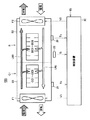
図2は、この発明の実施の形態1による冷却装置の全体構成図である。
図2を参照して、冷却装置40は、蓄電装置C1側に設置された冷却ファンF10と、バッテリB側に設置された排気口44と、冷却ファンF10から取り込まれた冷却風を通流させるための冷却風流路とを備える。
FIG. 2 is an overall configuration diagram of a cooling device according to Embodiment 1 of the present invention.
Referring to FIG. 2,
詳細には、蓄電装置C1は、筐体50を外装部材として、筐体50の底面上に搭載された複数個のキャパシタセルCC1〜CC5が収容された構造からなる。複数個のキャパシタセルCC1〜CC5の上面と筐体50との間、および積層されたキャパシタセルの間には、冷却風流路としての間隙が形成されている。この間隙は、後述するように、キャパシタセルCC1〜CC5に対して下流側において、バッテリBの筐体52に形成された間隙と連通している。
Specifically, the power storage device C1 has a structure in which a plurality of capacitor cells CC1 to CC5 mounted on the bottom surface of the
バッテリBは、筐体52を外装部材として、筐体52内部に積層された複数個の電池セルBC1〜BC6を搭載した基板が収容された構造からなる。電池セルBC1〜BC6の上面と筐体52との間、電池セルBC1〜BC6を搭載した基板の裏面と筐体52との間、および積層された電池セルの間には、冷却風流路としての間隙が形成されている。
The battery B has a structure in which a substrate on which a plurality of battery cells BC1 to BC6 stacked inside the
そして、バッテリBと蓄電装置C1とは、図2に示すように、筐体50の上方に筐体52が積層されるように配置される。このとき、筐体50と筐体52との接触面には開口部46が設けられ、筐体50内部の間隙と筐体52内部の間隙とが連通可能となっている。なお、開口部46は、冷却風流路のキャパシタセルCC1〜CC5に対して下流側に設けられる。
As shown in FIG. 2, the battery B and the power storage device C <b> 1 are arranged so that the
冷却ファンF10は、蓄電装置C1の筐体50の一方側面に配置される。冷却ファンF10の上流側には、冷却風を取り込むための吸気ダクト(図示せず)が設けられる。
Cooling fan F10 is disposed on one side surface of
排気口44は、バッテリBの筐体52の一方側面に配置される。排気口44の下流側には、冷却風流路を通流した冷却風を外部に排出するための排気ダクト(図示せず)が設けられる。
The
以上の構成において、送風ファンF10から取り込まれた冷却風は、図中の矢印で示す方向に沿って通流する。具体的には、冷却風は、最初に蓄電装置C1の筐体50内部に形成された間隙を通流する。これにより、キャパシタセルCC1〜CC5が冷却される。続いて、キャパシタセルCC1〜CC5を経由した冷却風は、開口部46を通じてバッテリBの筐体52内部に導入される。筐体52内部に導入された冷却風は、図中の矢印で示すように、電池セルBC1〜BC6を搭載した基板の裏面と筐体52との間の間隙を通流し、その後、電池セルBC1〜BC6の上面と筐体52との間の間隙に流れ込む。そして、冷却風は、電池セルBC1〜BC6の上面と筐体52との間の間隙、および電池セル間の間隙を通流して電池セルBC1〜BC6を冷却する。電池セルBC1〜BC6を冷却した後の冷却風は、排気口44を介して筐体52の外部へ排出される。
In the above configuration, the cooling air taken from the blower fan F10 flows along the direction indicated by the arrow in the drawing. Specifically, the cooling air first flows through the gap formed in the
図2の冷却装置40によれば、蓄電装置C1を冷却した後の冷却風を用いてバッテリBが冷却される。これは、以下に述べるように、蓄電装置C1がバッテリBに対して負荷駆動に伴なう充放電による発熱量が相対的に小さく、それゆえに、バッテリBに対して低温であることに基づく。
According to the
詳細には、図1のモータ駆動装置100において、蓄電装置C1を構成する電気二重層キャパシタは、バッテリBを構成する二次電池と比較して、急速な充放電が可能である。そのため、ハイブリッド自動車の加速時やエンジン始動時など短時間に大きな出力が必要とされる場合に、モータジェネレータMG1,MG2への電力供給を蓄電装置C1に主として行なわせることにより、モータ駆動時の応答性を確保することができる。
Specifically, in the
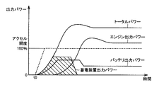
図3は、ハイブリッド自動車の加速時における出力パワー構成を説明するためのタイミングチャートである。 FIG. 3 is a timing chart for explaining the output power configuration during acceleration of the hybrid vehicle.
図3を参照して、時刻t0を起点としてアクセルが全開(アクセル開度が100%)されたことに応じて、車両全体の出力パワー(トータルパワー)は、エンジンによって発生された出力パワー(エンジン出力パワー)に、モータジェネレータMG2によって発生したパワーが加算されて増加する。 Referring to FIG. 3, the output power (total power) of the entire vehicle in response to the accelerator being fully opened (accelerator opening is 100%) starting from time t0 is the output power generated by the engine (engine The power generated by the motor generator MG2 is added to the output power) to increase.
このとき、モータジェネレータMG2では、バッテリBおよび蓄電装置C1から供給される電気エネルギーを源として出力パワーを発生する。そして、供給される電気エネルギーは、最初に、急速放電が可能な蓄電装置C1から出力パワーが供給され、これに追随してバッテリBから出力パワーが供給される構成となっている。なお、蓄電装置C1からの出力パワー(図中の斜線領域に相当)は、蓄電装置C1の端子間電圧Vcとモータ駆動装置100のシステム電圧(インバータ14,31の入力電圧Vmに相当)との電圧差に応じたものとなっている。
At this time, motor generator MG2 generates output power using electric energy supplied from battery B and power storage device C1 as a source. The supplied electrical energy is first supplied with output power from the power storage device C1 capable of rapid discharge, and the output power is supplied from the battery B following this. The output power from power storage device C1 (corresponding to the shaded area in the figure) is the voltage between terminals Vc of power storage device C1 and the system voltage of motor drive device 100 (corresponding to input voltage Vm of
これによれば、全開加速時には、蓄電装置C1からの迅速な電力供給によってモータジェネレータMG2の出力パワーが急峻に増加するため、車両全体の出力パワーを短時間で増加させることができる。これにより、滑らかで応答性の良い加速特性が実現される。 According to this, at the time of full opening acceleration, the output power of motor generator MG2 increases sharply due to the rapid power supply from power storage device C1, and therefore the output power of the entire vehicle can be increased in a short time. As a result, smooth and responsive acceleration characteristics are realized.
このように蓄電装置C1は、バッテリBのアシストを役割とするため、モータジェネレータMG2への電力供給時に通電される時間は、バッテリBの通電時間に対して相対的に短くなる。そのため、蓄電装置C1内部の発熱量は、バッテリB内部の発熱量と比べて少なく、蓄電装置C1がバッテリBよりも低温であることが一般的である。 Since power storage device C1 thus serves as an assist for battery B, the time during which power is supplied to motor generator MG2 is relatively short with respect to the time during which battery B is energized. Therefore, the heat generation amount inside the power storage device C1 is smaller than the heat generation amount inside the battery B, and the power storage device C1 is generally lower in temperature than the battery B.
そこで、本実施の形態による電源装置は、図1における冷却装置40に、図2に示す冷却構造を採用することにより、バッテリBおよび蓄電装置C1を共通の冷却風で冷却する構成とする。
Therefore, the power supply device according to the present embodiment employs a cooling structure shown in FIG. 2 in cooling
すなわち、冷却装置40は、冷却媒体流路において、低温側の蓄電装置C1を高温側のバッテリBの上流側に配置することを特徴とする。かかる配置を行なうことにより、蓄電装置C1を経由してバッテリBに冷却風を通流させることにより、共通の冷却風を用いてバッテリBおよび蓄電装置C1を冷却することができる。この結果、バッテリBおよび蓄電装置C1にそれぞれ冷却装置を設置するのに対し、モータ駆動装置全体を小型化することができる。
That is, the
そして、送風ファンF10から冷却風流路に供給される冷却風の送風量を、高温側のバッテリBの温度に基づいて決定することにより、双方を確実に冷却することができる。 And by determining the ventilation volume of the cooling air supplied from the blower fan F10 to the cooling air flow path based on the temperature of the battery B on the high temperature side, both can be reliably cooled.
具体的には、制御装置30は、温度センサ20からのバッテリ温度Tbに基づいて冷却ファンF10の送風量V10を決定し、その決定した送風量V10を指示する信号V10を生成して冷却ファンF10へ出力する。
Specifically, the
これにより、冷却ファンF10では、信号V10により指定された送風量V10となるように内部のファンモータを駆動するインバータの制御デューティ指令値が決定される。そして、その決定した制御デューティ指令値に基づいてインバータが補機バッテリからの直流電力を交流電力に変換してファンモータを駆動する。この結果、冷却ファンF10から取り込まれ、蓄電装置C1の上流側に供給された送風量V10の冷却風は、低温側の蓄電装置C1を最初に冷却し、その後高温側のバッテリBを冷却する。 As a result, in the cooling fan F10, the control duty command value of the inverter that drives the internal fan motor is determined so that the air flow rate V10 specified by the signal V10 is obtained. Then, based on the determined control duty command value, the inverter converts the DC power from the auxiliary battery into AC power to drive the fan motor. As a result, the cooling air of the blowing amount V10 taken in from the cooling fan F10 and supplied to the upstream side of the power storage device C1 cools the low temperature side power storage device C1 first, and then cools the high temperature side battery B.
さらに、図2の冷却装置40は、蓄電装置C1およびバッテリBを、筐体50の上方に筐体52が積層されるように配置することにより、バッテリBをより効率良く冷却することができる。
Furthermore, the
詳細には、電池セルBC1〜BC6の内部で発生した熱は、これらを搭載した基板および当該基板裏面に形成された間隙を介して蓄電装置C1の筐体52に伝搬する。すなわち、蓄電装置C1はバッテリBに対して低温であることから、電池セルBC1〜BC6は、冷却風との熱交換によって冷却されるのに加えて、蓄電装置C1の筐体52との熱交換によっても冷却される。この結果、バッテリBを効率良く冷却することができる。
Specifically, the heat generated inside the battery cells BC1 to BC6 propagates to the
なお、蓄電装置C1の筐体50に伝搬された熱は、筐体50内部を通流する冷却風に吸収されるため、キャパシタセルCC1〜CC5に伝わることはない。
In addition, since the heat propagated to the
[変更例]
図4は、この発明の実施の形態1の変更例による冷却装置の全体構成図である。なお、図4の冷却装置40Aは、図2の冷却装置40に対して、蓄電装置C1の筐体50とバッテリBの筐体52とが接触する部分の構造を変更したものである。よって、図2と重複する部分についての詳細な説明は繰り返さない。
[Example of change]
FIG. 4 is an overall configuration diagram of a cooling device according to a modification of the first embodiment of the present invention. Note that the
図4を参照して、バッテリBと蓄電装置C1とは、筐体50の上方に筐体52が積層されるように配置される。そして、筐体50の上方側面と筐体52の下方側面とは、接合面54により接合される。
Referring to FIG. 4, battery B and power storage device C <b> 1 are arranged such that
接合面54は、複数の開口部56を有する。複数の開口部56により、筐体50内部の間隙と筐体52内部の間隙とは連通している。
The
以上の構成において、送風ファンF10から取り込まれた冷却風は、図中の矢印で示す方向に沿って通流する。具体的には、冷却風は、最初に蓄電装置C1の筐体50内部に形成された間隙を通流する。これにより、キャパシタセルCC1〜CC5が冷却される。続いて、キャパシタセルCC1〜CC5を経由した冷却風は、複数の開口部56を通じてバッテリBの筐体52内部に導入される。筐体52内部に導入された冷却風は、図中の矢印で示すように、電池セルBC1〜BC6と筐体52との間の間隙、および電池セル間の間隙を通流して電池セルBC1〜BC6を冷却する。電池セルBC1〜BC6を冷却した後の冷却風は、排気口44を介して筐体52の外部へ排出される。
In the above configuration, the cooling air taken from the blower fan F10 flows along the direction indicated by the arrow in the drawing. Specifically, the cooling air first flows through the gap formed in the
すなわち、図4の冷却装置40Aにおいて、接合面54に設けられた複数の開口部56は、蓄電装置C1内部を通流した冷却風をバッテリB内部に導入するための通風孔として機能する。
That is, in the
ここで、複数の開口部56においては、冷却風流路に対して上流側に位置する開口部と下流側に位置する開口部とでは、冷却風の供給位置(送風ファンF10に相当)から流路長が異なる。そのため、両者では流路抵抗に伴なう圧力損失が異なり、送風量が不均一になる。これにより、開口部56を通過した冷却風の供給を受けるバッテリBにおいては、電池セルBC1〜BC6を均等に冷却することが困難となる。
Here, in the plurality of
そこで、本変更例による冷却装置40Aは、接合面54に配される複数の開口部56を、冷却風の流れる方向に沿って開口面積が異なるように形成する構成とする。
Therefore, the
具体的には、図5に示すように、複数の開口部56を、配置位置が冷却風流路に対して下流側になるに従って開口面積が大きくなるように形成する。図5の例では、吸気口44から最も近くに位置する開口部56aが最も開口面積が小さく、かつ、吸気口44から最も離れて位置する開口部56eが最も開口面積が大きくなるように形成される。なお、開口部56a〜56eの開口面積については、吸気口44から各々の開口部までの冷却風流路の流路長の違いによる圧力損失差がなくなるように設定される。
Specifically, as shown in FIG. 5, the plurality of
したがって、本変更例による冷却装置40Aによれば、個々の電池セルへの冷却風量を均一にすることができる。この結果、バッテリBを均等に冷却することができ、冷却効率を一段と高めることができる。
Therefore, according to the
以上のように、この発明の実施の形態1によれば、モータの電力供給源となるバッテリおよび蓄電装置を共通の冷却装置を用いて冷却することができるため、モータ駆動装置全体をコンパクトな構成とすることができる。 As described above, according to the first embodiment of the present invention, the battery and the power storage device that are the power supply source of the motor can be cooled using the common cooling device. It can be.
なお、本実施の形態では、バッテリの上方に蓄電装置を配置した構成について説明したが、冷却媒体流路に対して蓄電装置がバッテリの上流側に配置される限りにおいて、必ずしもバッテリと蓄電装置との位置関係を限定するものではない。したがって、蓄電装置の上方にバッテリを配置すること、または蓄電装置とバッテリとを水平方向に並べて配置する構成としても良い。 Note that in this embodiment, the configuration in which the power storage device is disposed above the battery has been described. However, as long as the power storage device is disposed on the upstream side of the battery with respect to the cooling medium flow path, the battery, the power storage device, and The positional relationship is not limited. Therefore, a battery may be arranged above the power storage device, or the power storage device and the battery may be arranged side by side in the horizontal direction.
[実施の形態2]
先の実施の形態1で説明したように、低温の蓄電装置C1の上方に高温のバッテリBを積層して配置し、かつ、低温の蓄電装置C1から高温のバッテリBに向かって冷却風が通流するように冷却風流路を形成することにより、共通の冷却風を用いて蓄電装置C1およびバッテリBの双方を効率良く冷却することができる。
[Embodiment 2]
As described in the first embodiment, the high temperature battery B is stacked on the upper side of the low temperature power storage device C1, and the cooling air passes from the low temperature power storage device C1 toward the high temperature battery B. By forming the cooling air flow path to flow, both the power storage device C1 and the battery B can be efficiently cooled using the common cooling air.
その一方で、低温環境下では、蓄電装置C1の温度が低下することによって蓄電装置C1の充放電可能電力が低下する場合が起こり得る。この場合、蓄電装置C1からの迅速な電力供給が不可能となるため、ハイブリッド車両の加速特性を悪化させることになる。 On the other hand, in a low temperature environment, the chargeable / dischargeable power of the power storage device C1 may decrease due to a decrease in the temperature of the power storage device C1. In this case, since rapid power supply from power storage device C1 is impossible, acceleration characteristics of the hybrid vehicle are deteriorated.
そこで、低温環境下、たとえば寒冷地などにおいては、図1の冷却装置40に図7に示す冷却構造を採用することにより、蓄電装置C1を昇温して充放電特性の低下を抑えることができる。
Therefore, in a low temperature environment, for example, in a cold region, the
図6は、この発明の実施の形態2による冷却装置の全体構成図である。
図6を参照して、冷却装置40Bは、図2の冷却装置40に対して、バッテリBと蓄電装置C1との配置における上下の位置関係を変更したものである。すなわち、バッテリBの筐体52の上方に蓄電装置C1の筐体50が積層されるように配置される。
FIG. 6 is an overall configuration diagram of a cooling device according to
Referring to FIG. 6,
バッテリBは、筐体52を外装部材として、筐体52の底面上に搭載された複数個の電池セルBC1〜BC6が収容された構造からなる。電池セルBC1〜BC6の上面と筐体52との間、および積層された電池セルの間には、冷却風流路としての間隙が形成されている。この間隙は、電池セルBC1〜BC6に対して下流側において、蓄電装置C1の筐体50に形成された間隙と連通している。
The battery B has a structure in which a plurality of battery cells BC1 to BC6 mounted on the bottom surface of the
蓄電装置C1は、筐体50を外装部材として、筐体50内部に積層された複数個のキャパシタセルCC1〜CC5を搭載した基板が収容された構造からなる。キャパシタセルCC1〜CC5の上面と筐体50との間、キャパシタセルCC1〜CC5を搭載した基板の裏面と筐体50との間、および積層されたキャパシタセルの間には、冷却風流路としての間隙が形成されている。
The power storage device C <b> 1 has a structure in which a substrate on which a plurality of capacitor cells CC <b> 1 to CC <b> 5 stacked inside the
そして、バッテリBと蓄電装置C1とは、図6に示すように、筐体52の上方に筐体50が積層されるように配置される。このとき、筐体52と筐体50との接触面には開口部46が設けられ、筐体52内部の間隙と筐体50内部の間隙とが連通可能となっている。なお、開口部46は、冷却風流路の電池セルBC1〜BC6に対して下流側に設けられる。
As shown in FIG. 6, the battery B and the power storage device C <b> 1 are arranged so that the
冷却ファンF10は、バッテリBの筐体52の一方側面に配置される。冷却ファンF10の上流側には、冷却風を取り込むための吸気ダクト(図示せず)が設けられる。
The cooling fan F <b> 10 is arranged on one side surface of the
排気口44は、蓄電装置C1の筐体50の一方側面に配置される。排気口44の下流側には、冷却風流路を通流した冷却風を外部に排出するための排気ダクト(図示せず)が設けられる。
The
以上の構成において、冷却ファンF10から取り込まれた冷却風は、図中の矢印で示す方向に沿って通流する。具体的には、冷却風は、最初にバッテリBの筐体52内部に形成された間隙を通流する。続いて、電池セルBC1〜BC6を経由した冷却風は、開口部46を通じて蓄電装置C1の筐体50内部に導入される。筐体50内部に導入された冷却風は、図中の矢印で示すように、キャパシタセルCC1〜CC5を搭載した基板の裏面と筐体50との間の間隙を通流し、その後、キャパシタセルCC1〜CC5の上面と筐体50との間の間隙に流れ込む。そして、冷却風は、キャパシタセルCC1〜CC5の上面と筐体50との間の間隙、およびキャパシタセル間の間隙を通流し、その後、排気口44を介して筐体50の外部へ排出される。
In the above configuration, the cooling air taken from the cooling fan F10 flows along the direction indicated by the arrow in the drawing. Specifically, the cooling air first flows through a gap formed inside the
図6の冷却装置40Bによれば、バッテリBとの間の熱交換によって暖められた冷却風は、蓄電装置C1を通流することにより、蓄電装置C1は、冷却風の熱エネルギーを回収して暖められる。したがって、冷却風を媒体としてバッテリBの放熱を用いて蓄電装置C1を昇温することにより、蓄電装置C1の充放電可能電力の低下を抑制することができる
さらに、冷却装置40Bによれば、蓄電装置C1およびバッテリBを筐体52の上方に筐体50が積層されるように配置したことにより、蓄電装置C1をより効率良く昇温することができる。
According to the
詳細には、電池セルBC1〜BC6の内部で発生した熱は、筐体52およびキャパシタセルCC1〜CC5が搭載された基板の裏面に形成された間隙を介して当該基板に伝搬する。キャパシタセルCC1〜CC5は、冷却風との熱交換により暖められるとともに、当該基板との熱交換によっても暖められる。この結果、蓄電装置C1を効率良く昇温することができる。
Specifically, heat generated in the battery cells BC1 to BC6 propagates to the substrate through a gap formed on the back surface of the substrate on which the
なお、図6の冷却装置40Bについても、バッテリBの筐体52と蓄電装置C1の筐体50の接合面に図5に示す構成を適用することができる。これによれば、バッテリBとの熱交換により暖められた冷却風がキャパシタセルCC1〜CC5に均等に供給されるため、キャパシタセルCC1〜CC5の温度むらをなくし、均等に昇温することができる。
6 can also be applied to the joint surface between the casing 52 of the battery B and the
以上のように、この発明の実施の形態2によれば、低温環境下では、バッテリから回収した熱エネルギーを用いて蓄電装置を昇温することができるため、電源装置の充放電電力の低下を抑制することができる。 As described above, according to the second embodiment of the present invention, the temperature of the power storage device can be raised using the thermal energy recovered from the battery in a low temperature environment. Can be suppressed.
[実施の形態3]
図7は、この発明の実施の形態3における冷却装置の概略構成図である。
[Embodiment 3]
FIG. 7 is a schematic configuration diagram of a cooling device according to Embodiment 3 of the present invention.
図7を参照して、冷却装置40Cは、蓄電装置C1側に設置された冷却ファンF1と、バッテリB側に設置された冷却ファンF2と、冷却ファンF1,F2から供給された冷却風を通流させるための冷却風流路とを備える。
Referring to FIG. 7,
具体的には、蓄電装置C1は、筐体50を外装部材として、筐体50内部に積層された複数個のキャパシタセルCC1〜CC5が収容された構造からなる。複数個のキャパシタセルCC1〜CC5は、基本的に同様の構造からなり、電気的に直列に接続される。キャパシタセルCC1〜CC5の上面および下面と筐体50との間、および、積層されたキャパシタセルの間には、冷却風を通流させることができるように、冷却風流路としての間隙が形成されている。
Specifically, the power storage device C1 has a structure in which a plurality of capacitor cells CC1 to CC5 stacked inside the
バッテリBは、筐体52を外装部材として、筐体52内部に積層された複数個の電池セルBC1〜BC6が収容された構造からなる。複数個の電池セルBC1〜BC6は、基本的に同様の構造からなり、電気的に直列に接続される。電池セルBC1〜BC6の上面および下面と筐体52との間、および、積層された電池セルの間には、冷却風を通流させることができるように、冷却風流路としての間隙が形成されている。
The battery B has a structure in which a plurality of battery cells BC1 to BC6 stacked inside the
冷却ファンF1は、蓄電装置C1の筐体50の一方側面に配置される。冷却ファンF1の上流側には、冷却風を取り込むための吸気ダクト(図示せず)が設けられる。
Cooling fan F1 is arranged on one side surface of
蓄電装置C1の筐体50の他方側面は、開口端面となっており、同じく開口端面を構成するバッテリBの筐体52の一方側面と連結される。すなわち、筐体50内部に形成された間隙と筐体52内部に形成された間隙とは連通しており、共通の冷却風流路を形成する。
The other side surface of the
冷却ファンF2は、バッテリBの筐体50の他方側面に配置される。冷却ファンF2の上流側には、冷却風を取り込むための吸気ダクト(図示せず)が設けられる。
The cooling fan F2 is disposed on the other side surface of the
そして、冷却ファンF1と冷却ファンF2とは、後述する方法によって制御装置30からの信号V1,V2に応じて選択的に駆動される。冷却ファンF1を選択的に駆動したときには、冷却ファンF1から取り込まれた冷却風は、冷却風流路を図中の矢印LN1で示す方向に沿って通流する。
The cooling fan F1 and the cooling fan F2 are selectively driven according to signals V1 and V2 from the
このとき、冷却風は、最初に、蓄電装置C1の筐体50内部に形成された間隙を通流してキャパシタセルCC1〜CC5を冷却し、続いて、バッテリBの筐体52内部に形成された間隙を通流して電池セルBC1〜BC6を冷却する。最後に、冷却ファンF2を排気口として外部に排出される。
At this time, the cooling air first flows through the gap formed inside the
すなわち、冷却ファンF1を駆動したときには、冷却風は、蓄電装置C1の上流側に供給され、蓄電装置C1を経由してバッテリBに通流する。これにより、バッテリBは、蓄電装置C1を冷却した後の冷却風により冷却される。 That is, when the cooling fan F1 is driven, the cooling air is supplied to the upstream side of the power storage device C1 and flows to the battery B via the power storage device C1. Thereby, battery B is cooled by the cooling air after cooling power storage device C1.
一方、冷却ファンF2を選択的に駆動したときには、冷却ファンF2から取り込まれた冷却風は、冷却風流路を図中の矢印LN2で示す方向に沿って通流する。 On the other hand, when the cooling fan F2 is selectively driven, the cooling air taken from the cooling fan F2 flows through the cooling air flow path along the direction indicated by the arrow LN2 in the drawing.
このとき、冷却風は、最初に、バッテリBの筐体52内部に形成された間隙を通流して電池セルBC1〜BC6を冷却し、続いて、蓄電装置C1の筐体50内部に形成された間隙を通流してキャパシタセルCC1〜CC5を冷却する。最後に、冷却ファンF1を排気口として外部に排出される。
At this time, the cooling air first flows through the gap formed inside the
すなわち、冷却ファンF2を駆動したときには、冷却風は、バッテリBの上流側に供給され、バッテリBを経由して蓄電装置C1に通流する。これにより、蓄電装置C1は、バッテリBを冷却した後の冷却風により冷却される。 That is, when the cooling fan F <b> 2 is driven, the cooling air is supplied to the upstream side of the battery B and flows through the battery B through the battery B. Thereby, power storage device C1 is cooled by the cooling air after cooling battery B.
以上のように、本実施の形態による冷却装置40Cによれば、共通の冷却風流路に設けられた冷却ファンF1,F2を選択的に駆動することにより、冷却風の流れる方向が切換えられる。冷却装置40Cは、先述の冷却装置40に対して、冷却ファンの個数が増えるものの、蓄電装置C1およびバッテリBを冷却する機能に加えて、これらの昇温する機能を併せ持つ。すなわち、冷却装置40Cは、蓄電装置C1およびバッテリBの温度調節装置を構成する。
As described above, according to the
以下に、冷却ファンF1,F2の駆動制御について説明する。
冷却ファンF1,F2の駆動制御は、制御装置30によって行なわれる。制御装置30は、温度センサ20からバッテリ温度Tbを受け、温度センサ21からキャパシタ温度Tcを受け、温度センサ22から電源装置周辺の雰囲気温度Tiを受ける。そして、制御装置30は、これらの温度情報に基づいて、駆動させる冷却ファンを選択する。
Hereinafter, drive control of the cooling fans F1 and F2 will be described.
The drive control of the cooling fans F1 and F2 is performed by the
詳細には、最初に、制御装置30は、雰囲気温度Tiが所定の閾値T_stdよりも高いか否かを判定する。なお、所定の閾値T_stdは、たとえばバッテリBの入出力可能電力に低下が見られるときの雰囲気温度Tiに設定される。そして、制御装置30は、その判定結果に応じて、以下に述べる方法によって駆動させる冷却ファンを選択する。これによれば、電源装置が常温時と低温時とでは異なる方法によって駆動用の冷却ファンが選択される。
Specifically, first, the
(1)電源装置が常温状態のとき
制御装置30は、雰囲気温度Tiが所定の閾値T_stdよりも高いと判定されると、続いて、バッテリ温度Tbがキャパシタ温度Tcよりも高いか否かを判定する。
(1) When the power supply device is in the normal temperature state When the
このとき、バッテリ温度Tbがキャパシタ温度Tcよりも高いと判定されたときには、制御装置30は、冷却ファンF1を駆動用の冷却ファンに選択する。そして、制御装置30は、バッテリ温度Tbに基づいて冷却ファンF1の送風量V1を決定し、その決定した送風量V1を指示する信号V1を生成して冷却ファンF1へ出力する。
At this time, when it is determined that the battery temperature Tb is higher than the capacitor temperature Tc, the
これにより、冷却ファンF1では、信号V1により指定された送風量V1となるように内部のファンモータを駆動するインバータの制御デューティ指令値が決定される。そして、その決定した制御デューティ指令値に基づいてインバータが補機バッテリからの直流電力を交流電力に変換してファンモータを駆動する。この結果、冷却ファンF1から取り込まれ、蓄電装置C1の上流側に供給された送風量V1の冷却風は、低温側の蓄電装置C1を最初に冷却し、その後高温側のバッテリBを冷却する。 As a result, in the cooling fan F1, the control duty command value of the inverter that drives the internal fan motor is determined so that the air flow rate V1 specified by the signal V1 is obtained. Then, based on the determined control duty command value, the inverter converts the DC power from the auxiliary battery into AC power to drive the fan motor. As a result, the cooling air of the blowing amount V1 taken in from the cooling fan F1 and supplied to the upstream side of the power storage device C1 cools the low temperature side power storage device C1 first, and then cools the high temperature side battery B.
一方、バッテリ温度Tbがキャパシタ温度Tc以下と判定されたときには、制御装置30は、冷却ファンF2を駆動用の冷却ファンに選択する。そして、制御装置30は、キャパシタ温度Tcに基づいて冷却ファンF2の送風量V2を決定し、その決定した送風量V2を指示する信号V2を生成して冷却ファンF2へ出力する。
On the other hand, when it is determined that the battery temperature Tb is equal to or lower than the capacitor temperature Tc, the
これにより、冷却ファンF2では、信号V2により指定された送風量V2となるように内部のファンモータを駆動するインバータの制御デューティ指令値が決定される。そして、その決定した制御デューティ指令値に基づいてインバータが補機バッテリからの直流電力を交流電力に変換してファンモータを駆動する。この結果、冷却ファンF2から取り込まれ、バッテリBの上流側に供給された送風量V2の冷却風は、低温側のバッテリBを最初に冷却し、その後高温側の蓄電装置C1を冷却する。 As a result, in the cooling fan F2, the control duty command value of the inverter that drives the internal fan motor is determined so that the air flow rate V2 specified by the signal V2 is obtained. Then, based on the determined control duty command value, the inverter converts the DC power from the auxiliary battery into AC power to drive the fan motor. As a result, the cooling air of the blowing amount V2 taken in from the cooling fan F2 and supplied to the upstream side of the battery B cools the battery B on the low temperature side first, and then cools the power storage device C1 on the high temperature side.
以上のように、電源装置の雰囲気温度Tiが所定の閾値T_stdよりも高いとき、すなわち、電源装置が常温状態にあるときには、低温側の蓄電装置C1(またはバッテリB)から高温側のバッテリB(または蓄電装置C1)に向かって冷却風を通流させることにより、共通の冷却風を用いてバッテリBおよび蓄電装置C1を冷却することができる。 As described above, when the ambient temperature Ti of the power supply device is higher than the predetermined threshold T_std, that is, when the power supply device is in a normal temperature state, the low-temperature side power storage device C1 (or battery B) to the high-temperature side battery B ( Alternatively, the battery B and the power storage device C1 can be cooled using the common cooling air by passing the cooling air toward the power storage device C1).
さらに、冷却風の送風量を高温側のバッテリB(または蓄電装置C1)の温度に基づいて決定することにより、双方を確実に冷却することができる。 Furthermore, both can be reliably cooled by determining the ventilation volume of cooling air based on the temperature of the battery B (or power storage device C1) on the high temperature side.
(2)電源装置が低温状態のとき
制御装置30は、雰囲気温度Tiが所定の閾値T_std以下と判定されたときには、続いて、バッテリ温度Tbがキャパシタ温度Tcよりも高いか否かを判定する。
(2) When the power supply device is in a low temperature state When it is determined that the ambient temperature Ti is equal to or lower than the predetermined threshold T_std, the
そして、バッテリ温度Tbがキャパシタ温度Tcよりも高いと判定されたとき、制御装置30は、冷却ファンF2を駆動用の冷却ファンに選択する。そして、制御装置30は、バッテリ温度Tbに基づいて冷却ファンF2の送風量V2を決定し、その決定した送風量V2を指示する信号V2を生成して冷却ファンF2へ出力する。
When it is determined that the battery temperature Tb is higher than the capacitor temperature Tc, the
これにより、冷却ファンF2では、信号V2により指定された送風量V2となるように内部のファンモータを駆動するインバータの制御デューティ指令値が決定され、その決定した制御デューティ指令値に基づいてファンモータが駆動される。この結果、冷却ファンF2から取り込まれ、バッテリBの上流側に供給された送風量V2の冷却風は、高温側のバッテリBを経由して低温側の蓄電装置C1を通流する。 Thereby, in the cooling fan F2, the control duty command value of the inverter that drives the internal fan motor is determined so as to be the air flow rate V2 specified by the signal V2, and the fan motor is based on the determined control duty command value. Is driven. As a result, the cooling air of the blowing amount V2 taken in from the cooling fan F2 and supplied to the upstream side of the battery B flows through the low temperature side power storage device C1 via the high temperature side battery B.
このとき、バッテリBとの間の熱交換によって暖められた冷却風は、蓄電装置C1を通流する。これにより、蓄電装置C1は、冷却風の熱エネルギーを回収して暖められる。蓄電装置C1を構成する電気二重層キャパシタは、静電容量に温度依存性を有しており、バッテリBと同様に、温度の低下により充放電可能電力が低下するという性質を有する。そのため、蓄電装置C1が低温時においては、冷却風を媒体としてバッテリBの熱を用いて蓄電装置C1を昇温することにより、充放電可能電力の低下を抑制することができる。 At this time, the cooling air heated by the heat exchange with the battery B flows through the power storage device C1. Thereby, power storage device C1 recovers the heat energy of the cooling air and is warmed. The electric double layer capacitor that constitutes the power storage device C1 has a temperature dependency on the electrostatic capacity, and, like the battery B, has a property that chargeable / dischargeable power decreases due to a decrease in temperature. Therefore, when the power storage device C1 is at a low temperature, the temperature of the power storage device C1 is raised by using the heat of the battery B using the cooling air as a medium, so that a decrease in chargeable / dischargeable power can be suppressed.
一方、バッテリ温度Tbがキャパシタ温度Tc以下と判定されたときには、制御装置30は、冷却ファンF1を駆動用の冷却ファンに選択する。そして、制御装置30は、キャパシタ温度Tcに基づいて冷却ファンF1の送風量V1を決定し、その決定した送風量V1を指示する信号V1を生成して冷却ファンF1へ出力する。
On the other hand, when battery temperature Tb is determined to be equal to or lower than capacitor temperature Tc,
これにより、冷却ファンF1では、信号V1により指定された送風量V1となるように内部のファンモータを駆動するインバータの制御デューティ指令値が決定され、その決定した制御デューティ指令値に基づいてファンモータが駆動される。この結果、冷却ファンF1から取り込まれ、蓄電装置C1の上流側に供給された送風量V1の冷却風は、高温側の蓄電装置C1を経由して低温側のバッテリBを通流する。 Thereby, in the cooling fan F1, the control duty command value of the inverter that drives the internal fan motor is determined so that the air flow rate V1 specified by the signal V1 is obtained, and the fan motor is based on the determined control duty command value. Is driven. As a result, the cooling air of the blowing amount V1 taken in from the cooling fan F1 and supplied to the upstream side of the power storage device C1 flows through the low temperature side battery B via the high temperature side power storage device C1.
このとき、蓄電装置C1との間の熱交換によって暖められた冷却風は、バッテリBを通流する。これにより、バッテリBは、冷却風の熱エネルギーを回収して暖められ、充放電可能電力の低下が抑えられる。 At this time, the cooling air heated by heat exchange with the power storage device C1 flows through the battery B. Thereby, the battery B collects the thermal energy of the cooling air and is warmed, and the decrease in chargeable / dischargeable power is suppressed.
以上のように、電源装置の雰囲気温度Tiが所定の閾値T_std以下のとき、すなわち、電源装置が低温状態にあるときには、高温側のバッテリB(または蓄電装置C1)から低温側の蓄電装置C1(またはバッテリB)に向かって冷却風を通流させることにより、低温側の蓄電装置C1(またはバッテリB)を昇温することができる。この結果、低温環境下におけるバッテリBおよび蓄電装置C1の充放電可能電力の低下を防止し、本来のハイブリッド車両の燃費性能を発揮することができる。 As described above, when the ambient temperature Ti of the power supply device is equal to or lower than the predetermined threshold T_std, that is, when the power supply device is in a low temperature state, the battery B (or power storage device C1) on the high temperature side to the power storage device C1 ( Alternatively, the temperature of the low-temperature power storage device C1 (or battery B) can be raised by allowing cooling air to flow toward the battery B). As a result, it is possible to prevent a decrease in chargeable / dischargeable power of the battery B and the power storage device C1 in a low temperature environment, and to exhibit the fuel efficiency performance of the original hybrid vehicle.
図8および図9は、図7の冷却装置40Cの駆動制御を説明するためのフローチャートである。なお、以下の駆動制御は、モータ駆動装置100全体の制御を担う制御装置30によって実行される。
8 and 9 are flowcharts for explaining drive control of the
図8を参照して、最初に、イグニッションキーIGがオンされたことに応じて(ステップS01)、制御装置30は、電源装置の雰囲気温度Tiが所定の閾値T_stdよりも高いか否かを判定する(ステップS02)。ステップS02において、雰囲気温度Tiが所定の閾値T_stdよりも高いと判定されると、すなわち、電源装置が常温環境下にあると判定されると、制御装置30は、続いて、バッテリ温度Tbがキャパシタ温度Tcよりも高いか否かを判定する(ステップS03)。
Referring to FIG. 8, first, in response to ignition key IG being turned on (step S01),
ステップS03において、バッテリ温度Tbがキャパシタ温度Tcよりも高いと判定されると、制御装置30は、冷却ファンF1を駆動用の冷却ファンに選択して作動させる。(ステップS04)。そして、制御装置30は、バッテリ温度Tbに基づいて冷却ファンF1の送風量V1を決定し、その決定した送風量V1を指示する信号V1を生成して冷却ファンF1へ出力する(ステップS05)。これにより、冷却ファンF1から取り込まれ、蓄電装置C1の上流側に供給された送風量V1の冷却風は、低温側の蓄電装置C1を経由して高温側のバッテリBへと通流し、それぞれを冷却する(ステップS06)。
If it is determined in step S03 that the battery temperature Tb is higher than the capacitor temperature Tc, the
一方、ステップS03において、バッテリ温度Tbがキャパシタ温度Tc以下と判定されると、制御装置30は、冷却ファンF2を駆動用の冷却ファンに選択して作動させる。(ステップS07)。そして、制御装置30は、キャパシタ温度Tcに基づいて冷却ファンF2の送風量V2を決定し、その決定した送風量V2を指示する信号V2を生成して冷却ファンF2へ出力する(ステップS08)。これにより、冷却ファンF2から取り込まれ、バッテリBの上流側に供給された送風量V2の冷却風は、低温側のバッテリBを経由して高温側の蓄電装置C1へと通流し、それぞれを冷却する(ステップS09)。
On the other hand, when it is determined in step S03 that the battery temperature Tb is equal to or lower than the capacitor temperature Tc, the
次に、図9を参照して、制御装置30は、図8のステップS02において雰囲気温度Tiが所定の閾値T_std以下と判定されると、すなわち、電源装置が低温環境下にあると判定されると、続いて、バッテリ温度Tbがキャパシタ温度Tcよりも高いか否かを判定する(ステップS10)。
Next, referring to FIG. 9,
ステップS10において、バッテリ温度Tbがキャパシタ温度Tcよりも高いと判定されると、制御装置30は、冷却ファンF2を駆動用の冷却ファンに選択して作動させる。(ステップS11)。そして、制御装置30は、バッテリ温度Tbに基づいて冷却ファンF2の送風量V2を決定し、その決定した送風量V2を指示する信号V2を生成して冷却ファンF2へ出力する(ステップS12)。これにより、冷却ファンF2から取り込まれ、バッテリBの上流側に供給された送風量V2の冷却風は、高温側のバッテリBを経由して低温側の蓄電装置C1へと通流する(ステップS13)。この結果、蓄電装置C1は、冷却風からバッテリBの放熱による熱エネルギーを吸収して昇温する。
In step S10, when it is determined that the battery temperature Tb is higher than the capacitor temperature Tc, the
一方、ステップS10において、バッテリ温度Tbがキャパシタ温度Tc以下と判定されると、制御装置30は、冷却ファンF1を駆動用の冷却ファンに選択して作動させる。(ステップS14)。そして、制御装置30は、キャパシタ温度Tcに基づいて冷却ファンF1の送風量V1を決定し、その決定した送風量V1を指示する信号V1を生成して冷却ファンF1へ出力する(ステップS15)。これにより、冷却ファンF1から取り込まれ、蓄電装置C1の上流側に供給された送風量V1の冷却風は、高温側の蓄電装置C1を経由して低温側のバッテリBへと通流する(ステップS16)。この結果、バッテリBは、冷却風から蓄電装置C1の放熱による熱エネルギーを吸収して昇温する。
On the other hand, when it is determined in step S10 that the battery temperature Tb is equal to or lower than the capacitor temperature Tc, the
以上のように、この発明の実施の形態3によれば、モータの電力供給源となるバッテリおよび蓄電装置を共通の冷却風を用いて冷却することができるとともに、低温環境下では、一方から回収した熱エネルギーを用いて他方を昇温することができる。この結果、バッテリおよび蓄電装置は所定の許容温度範囲内に調整されるため、性能劣化を抑制することができる。 As described above, according to the third embodiment of the present invention, the battery and the power storage device that are the power supply source of the motor can be cooled using the common cooling air, and are recovered from one side in the low temperature environment. The other can be heated using the thermal energy. As a result, since the battery and the power storage device are adjusted within a predetermined allowable temperature range, performance deterioration can be suppressed.
なお、上記の実施の形態1〜3では動力分割機構によりエンジンの動力を車軸と発電機とに分割して伝達可能なシリーズ/パラレル型ハイブリッド自動車に適用した例を示した。しかし本発明は、発電機を駆動するためにエンジンを用い、発電機により発電された電力を使うモータでのみ車軸の駆動力を発生させるシリーズ型ハイブリッド自動車や、モータのみで走行する電気自動車にも適用できる。これらの構成はいずれも、車軸とモータまたは発電機とが接続されており、減速時の回生エネルギーを回収しバッテリおよびキャパシタに蓄えることが可能であるため、本発明を適用することができる。 In the first to third embodiments, an example is shown in which the present invention is applied to a series / parallel type hybrid vehicle in which the power of the engine can be divided and transmitted to the axle and the generator by the power split mechanism. However, the present invention also applies to a series-type hybrid vehicle that uses an engine to drive a generator and generates axle driving force only by a motor that uses electric power generated by the generator, and an electric vehicle that runs only by a motor. Applicable. In any of these configurations, the axle and the motor or the generator are connected, and the regenerative energy at the time of deceleration can be collected and stored in the battery and the capacitor, so that the present invention can be applied.
今回開示された実施の形態はすべての点で例示であって制限的なものではないと考えられるべきである。本発明の範囲は上記した説明ではなく、特許請求の範囲によって示され、特許請求の範囲と均等の意味および範囲内でのすべての変更が含まれることが意図される。 The embodiment disclosed this time should be considered as illustrative in all points and not restrictive. The scope of the present invention is defined by the terms of the claims, rather than the description above, and is intended to include any modifications within the scope and meaning equivalent to the terms of the claims.
この発明は、負荷への電力供給源として電源と蓄電装置とを有する電源装置および電源装置の冷却方法に適用することができる。 The present invention can be applied to a power supply device having a power supply and a power storage device as a power supply source to a load, and a method for cooling the power supply device.
10,11,13 電圧センサ、12 昇圧コンバータ、14,31 インバータ、20〜22 温度センサ、24,28 電流センサ、30 制御装置、40,40A〜40C 冷却装置、44 排気口、46,56,56a〜56e 開口部、100 モータ駆動装置、B バッテリ、BC1〜BC6 電池セル、C1 蓄電装置、C2 コンデンサ、CC1〜CC5 キャパシタセル、ENG エンジン、F1,F2,F10 冷却ファン、MG1,MG2 モータジェネレータ、PL1 電源ライン、PL2 アースライン、PSD 動力分割機構、R1 抵抗、SRB1〜SRB3,SRC1,SRC2 システムリレー。 10, 11, 13 Voltage sensor, 12 Boost converter, 14, 31 Inverter, 20-22 Temperature sensor, 24, 28 Current sensor, 30 Control device, 40, 40A-40C Cooling device, 44 Exhaust port, 46, 56, 56a ˜56e opening, 100 motor drive device, B battery, BC1 to BC6 battery cell, C1 power storage device, C2 capacitor, CC1 to CC5 capacitor cell, ENG engine, F1, F2, F10 cooling fan, MG1, MG2 motor generator, PL1 Power supply line, PL2 ground line, PSD power split mechanism, R1 resistance, SRB1-SRB3, SRC1, SRC2 system relay.
Claims (9)
前記負荷に対して前記第1電源と並列に接続され、前記第1電源の不足電力をアシストして前記負荷へ電力を供給し、前記負荷の駆動に伴なう充放電による発熱量が相対的に小さい第2電源と、
前記第1電源および前記第2電源を冷却するための冷却装置とを備え、
前記冷却装置は、
冷却媒体を前記第2電源の上流部に供給する冷却媒体供給部と、
前記冷却媒体供給部により供給された前記冷却媒体を、前記第2電源を経由して前記第1電源に通流させるように形成された冷却媒体流路とを含み、
前記第1電源は、
複数個の第1電源セルが第1の主表面に搭載される第1の基板と、
前記第1の基板を収容し、前記冷却媒体流路を通流する前記冷却媒体を電源装置外部へ排出するための第1連通路が設けられた第1の筐体とを含み、
前記第2電源は、
複数個の第2電源セルが第1の主表面に搭載される第2の基板と、
前記第2の基板を収容し、前記冷却媒体を前記冷却媒体供給部から前記冷却媒体流路に導入するための第2連通路が設けられた第2の筐体とを含み、
前記第1連通路と前記第2連通路とは、第3連通路により連通可能に繋がれ、
前記第2の筐体は、前記第1の基板の第2の主表面と熱伝導可能なように前記第1の筐体に接触して配置される、電源装置。 A first power source provided so as to be able to supply power to a load, and having a relatively large amount of heat generated by charging and discharging accompanying driving of the load;
The load is connected in parallel with the first power supply to the load, assists the insufficient power of the first power supply to supply power to the load, and the amount of heat generated by charge / discharge accompanying the driving of the load is relatively A very small second power source,
A cooling device for cooling the first power source and the second power source,
The cooling device is
A cooling medium supply unit for supplying a cooling medium to an upstream part of the second power source;
A cooling medium flow path formed to allow the cooling medium supplied by the cooling medium supply unit to flow to the first power supply via the second power supply,
The first power source is
A first substrate on which a plurality of first power cells are mounted on a first main surface;
And a first housing provided with a first communication path for accommodating the first substrate and discharging the cooling medium flowing through the cooling medium flow path to the outside of the power supply device,
The second power source is
A second substrate on which a plurality of second power cells are mounted on the first main surface;
A second housing that houses the second substrate and is provided with a second communication path for introducing the cooling medium from the cooling medium supply unit into the cooling medium flow path;
The first communication path and the second communication path are connected to be able to communicate with each other through a third communication path,
The power supply device, wherein the second casing is disposed in contact with the first casing so as to be able to conduct heat with the second main surface of the first substrate.
前記複数の通風孔は、前記冷却媒体供給部との間の距離が長くなるに従って開口面積が大きくなるように形成される、請求項1に記載の電源装置。 The third communication path includes a plurality of ventilation holes formed on a joint surface between the first casing and the second casing.
2. The power supply device according to claim 1, wherein the plurality of ventilation holes are formed such that an opening area increases as a distance from the cooling medium supply unit increases.
前記負荷に対して前記第1電源と並列に接続され、前記第1電源の不足電力をアシストして前記負荷へ電力を供給し、前記負荷の駆動に伴なう充放電による発熱量が相対的に小さい第2電源と、
前記第1電源および前記第2電源の温度調整を行なう温度調整装置とを備え、
前記温度調整装置は、
冷却媒体を前記第1電源の上流部に供給する冷却媒体供給部と、
前記冷却媒体供給部から供給された前記冷却媒体を、前記第1電源を経由して前記第2電源に通流させるように形成された冷却媒体流路とを含み、
前記第1電源は、
複数個の第1電源セルが第1の主表面に搭載される第1の基板と、
前記第1の基板を収容し、前記冷却媒体流路を通流する前記冷却媒体を電源装置外部へ排出するための第1連通路が設けられた第1の筐体とを含み、
前記第2電源は、
複数個の第2電源セルが第1の主表面に搭載される第2の基板と、
前記第2の基板を収容し、前記冷却媒体を前記冷却媒体供給部から前記冷却媒体流路に導入するための第2連通路が設けられた第2の筐体とを含み、
前記第1連通路と前記第2連通路とは、第3連通路により連通可能に繋がれ、
前記第1の筐体は、前記第2の基板の第2の主表面と熱伝導可能なように前記第2の筐体に接触して配置される、電源装置。 A first power source provided so as to be able to supply power to a load, and having a relatively large amount of heat generated by charging and discharging accompanying driving of the load;
The load is connected in parallel with the first power supply to the load, assists the insufficient power of the first power supply to supply power to the load, and the amount of heat generated by charge / discharge accompanying the driving of the load is relatively A very small second power source,
A temperature adjusting device for adjusting the temperature of the first power source and the second power source,
The temperature adjusting device is:
A cooling medium supply unit for supplying a cooling medium to an upstream part of the first power source;
A cooling medium flow path formed so as to flow the cooling medium supplied from the cooling medium supply unit to the second power supply via the first power supply,
The first power source is
A first substrate on which a plurality of first power cells are mounted on a first main surface;
And a first housing provided with a first communication path for accommodating the first substrate and discharging the cooling medium flowing through the cooling medium flow path to the outside of the power supply device,
The second power source is
A second substrate on which a plurality of second power cells are mounted on the first main surface;
A second housing that houses the second substrate and is provided with a second communication path for introducing the cooling medium from the cooling medium supply unit into the cooling medium flow path;
The first communication path and the second communication path are connected to be able to communicate with each other through a third communication path,
The first housing is disposed in contact with the second housing so as to be able to conduct heat with the second main surface of the second substrate.
前記複数の通風孔は、前記冷却媒体供給部との間の距離が長くなるに従って開口面積が大きくなるように形成される、請求項3に記載の電源装置。 The third communication path includes a plurality of ventilation holes formed on a joint surface between the first casing and the second casing.
The power supply device according to claim 3, wherein the plurality of ventilation holes are formed such that an opening area increases as a distance from the cooling medium supply unit increases.
前記負荷に対して前記第1電源と並列に接続され、前記第1電源の不足電力をアシストして前記負荷へ電力を供給可能に設けられた第2電源と、
前記第1電源および前記第2電源の温度調整を行なう温度調整装置とを備え、
前記温度調整装置は、
前記第1電源と前記第2電源とが冷却媒体の通流方向に沿って直列に配置されるように形成された冷却媒体流路と、
前記冷却媒体流路の前記第1電源側の一方端に設けられ、前記第1電源の上流部に前記冷却媒体を供給する第1の冷却媒体供給部と、
前記冷却媒体流路の前記第2電源側の他方端に設けられ、前記第2電源の上流部に前記冷却媒体を供給する第2の冷却媒体供給部と、
電源装置の雰囲気温度、前記第1電源の温度および前記第2電源の温度に基づいて、前記第1の冷却媒体供給部および前記第2の冷却媒体供給部のいずれか一方を選択的に作動させる選択手段とを含み、
前記選択手段は、前記電源装置の雰囲気温度が所定の閾値よりも高いとき、前記第1電源の温度が前記第2電源の温度よりも高いことに応じて、前記第1の冷却媒体供給部を選択する一方で、前記第2電源の温度が前記第1電源の温度よりも高いことに応じて、前記第2の冷却媒体供給部を選択する、電源装置。 A first power source provided to supply power to a load;
A second power source connected in parallel to the first power source with respect to the load, and capable of supplying power to the load by assisting in insufficient power of the first power source;
A temperature adjusting device for adjusting the temperature of the first power source and the second power source,
The temperature adjusting device is:
A coolant flow path formed such that the first power supply and the second power supply are arranged in series along the flow direction of the coolant;
A first cooling medium supply section that is provided at one end of the cooling medium flow path on the first power supply side and supplies the cooling medium to an upstream portion of the first power supply;
A second cooling medium supply section that is provided at the other end of the cooling medium flow path on the second power supply side and supplies the cooling medium to an upstream portion of the second power supply;
Based on the ambient temperature of the power supply device, the temperature of the first power supply, and the temperature of the second power supply, either one of the first cooling medium supply unit and the second cooling medium supply unit is selectively operated. only contains a selection means,
When the ambient temperature of the power supply device is higher than a predetermined threshold, the selection means is configured to switch the first cooling medium supply unit in response to the temperature of the first power supply being higher than the temperature of the second power supply. While selecting , the power supply device which selects the 2nd cooling medium supply part according to the temperature of the 2nd power supply being higher than the temperature of the 1st power supply.
前記負荷に対して前記第1電源と並列に接続され、前記第1電源の不足電力をアシストして前記負荷へ電力を供給可能に設けられた第2電源と、
前記第1電源および前記第2電源の温度調整を行なう温度調整装置とを備え、
前記温度調整装置は、
前記第1電源と前記第2電源とが冷却媒体の通流方向に沿って直列に配置されるように形成された冷却媒体流路と、
前記冷却媒体流路の前記第1電源側の一方端に設けられ、前記第1電源の上流4部に前記冷却媒体を供給する第1の冷却媒体供給部と、
前記冷却媒体流路の前記第2電源側の他方端に設けられ、前記第2電源の上流部に前記冷却媒体を供給する第2の冷却媒体供給部と、
電源装置の雰囲気温度、前記第1電源の温度および前記第2電源の温度に基づいて、前記第1の冷却媒体供給部および前記第2の冷却媒体供給部のいずれか一方を選択的に作動させる選択手段とを含み、
前記選択手段は、前記電源装置の雰囲気温度が所定の閾値以下のとき、前記第1電源の温度が前記第2電源の温度よりも高いことに応じて、前記第2の冷却媒体供給部を選択する一方で、前記第2電源の温度が前記第1電源の温度よりも高いことに応じて、前記第1の冷却媒体供給部を選択する、電源装置。 A first power source provided to supply power to a load;
A second power source connected in parallel to the first power source with respect to the load, and capable of supplying power to the load by assisting in insufficient power of the first power source;
A temperature adjusting device for adjusting the temperature of the first power source and the second power source,
The temperature adjusting device is:
A coolant flow path formed such that the first power supply and the second power supply are arranged in series along the flow direction of the coolant;
A first cooling medium supply unit that is provided at one end of the cooling medium flow path on the first power supply side and supplies the cooling medium to the upstream four parts of the first power supply;
A second cooling medium supply section that is provided at the other end of the cooling medium flow path on the second power supply side and supplies the cooling medium to an upstream portion of the second power supply;
Based on the ambient temperature of the power supply device, the temperature of the first power supply, and the temperature of the second power supply, either one of the first cooling medium supply unit and the second cooling medium supply unit is selectively operated. only contains a selection means,
The selection unit selects the second cooling medium supply unit according to the fact that the temperature of the first power supply is higher than the temperature of the second power supply when the ambient temperature of the power supply apparatus is equal to or lower than a predetermined threshold. On the other hand , the power supply device that selects the first cooling medium supply unit in response to the temperature of the second power supply being higher than the temperature of the first power supply.
前記制御手段は、前記第1電源の温度が前記第2電源の温度よりも高いとき、前記第1電源の温度に基づいて前記冷却媒体の供給量を決定し、かつ、前記第2電源の温度が前記第1電源の温度よりも高いとき、前記第2電源の温度に基づいて前記冷却媒体の供給量を決定する、請求項6に記載の電源装置。 Control means for controlling the supply amount of the cooling medium to the cooling medium flow path;
When the temperature of the first power source is higher than the temperature of the second power source, the control means determines the supply amount of the cooling medium based on the temperature of the first power source, and the temperature of the second power source The power supply device according to claim 6 , wherein when the temperature is higher than the temperature of the first power supply, the supply amount of the cooling medium is determined based on the temperature of the second power supply.
前記電源装置は、車両に前記モータの電力供給源として搭載される、請求項1から請求項8のいずれか1項に記載の電源装置。 The load is a motor for driving a vehicle,
The power supply device according to any one of claims 1 to 8 , wherein the power supply device is mounted on a vehicle as a power supply source of the motor.
Priority Applications (10)
| Application Number | Priority Date | Filing Date | Title |
|---|---|---|---|
| JP2006141352A JP5034316B2 (en) | 2006-05-22 | 2006-05-22 | Power supply |
| CN200780018775XA CN101449419B (en) | 2006-05-22 | 2007-05-10 | Power supply device |
| EP20070743526 EP2026404B1 (en) | 2006-05-22 | 2007-05-10 | Power supply device |
| EP20100187532 EP2302726B1 (en) | 2006-05-22 | 2007-05-10 | Power supply unit |
| PCT/JP2007/060091 WO2007135934A1 (en) | 2006-05-22 | 2007-05-10 | Power supply device |
| BRPI0712257A BRPI0712257B8 (en) | 2006-05-22 | 2007-05-10 | power supply unit |
| KR1020087030904A KR101064889B1 (en) | 2006-05-22 | 2007-05-10 | Power supply device |
| US12/227,120 US7924562B2 (en) | 2006-05-22 | 2007-05-10 | Power supply unit |
| CA 2760498 CA2760498C (en) | 2006-05-22 | 2007-05-10 | Power supply unit |
| CA 2651139 CA2651139C (en) | 2006-05-22 | 2007-05-10 | Power supply unit |
Applications Claiming Priority (1)
| Application Number | Priority Date | Filing Date | Title |
|---|---|---|---|
| JP2006141352A JP5034316B2 (en) | 2006-05-22 | 2006-05-22 | Power supply |
Publications (3)
| Publication Number | Publication Date |
|---|---|
| JP2007311290A JP2007311290A (en) | 2007-11-29 |
| JP2007311290A5 JP2007311290A5 (en) | 2008-11-13 |
| JP5034316B2 true JP5034316B2 (en) | 2012-09-26 |
Family
ID=38723246
Family Applications (1)
| Application Number | Title | Priority Date | Filing Date |
|---|---|---|---|
| JP2006141352A Active JP5034316B2 (en) | 2006-05-22 | 2006-05-22 | Power supply |
Country Status (8)
| Country | Link |
|---|---|
| US (1) | US7924562B2 (en) |
| EP (2) | EP2026404B1 (en) |
| JP (1) | JP5034316B2 (en) |
| KR (1) | KR101064889B1 (en) |
| CN (1) | CN101449419B (en) |
| BR (1) | BRPI0712257B8 (en) |
| CA (2) | CA2651139C (en) |
| WO (1) | WO2007135934A1 (en) |
Families Citing this family (82)
| Publication number | Priority date | Publication date | Assignee | Title |
|---|---|---|---|---|
| JP5034316B2 (en) | 2006-05-22 | 2012-09-26 | トヨタ自動車株式会社 | Power supply |
| JP4434220B2 (en) * | 2007-03-06 | 2010-03-17 | トヨタ自動車株式会社 | Cooling apparatus for electrical equipment, cooling method thereof, program for causing computer to realize cooling method, and recording medium recording the program |
| CZ2008169A3 (en) * | 2008-03-14 | 2009-09-23 | Ydun, S. R. O. | Lead-free starting accumulator battery intended particularly for internal combustion engines and motor vehicles |
| DE102008051085A1 (en) * | 2008-10-09 | 2010-04-15 | Dr.Ing.H.C.F.Porsche Aktiengesellschaft | battery assembly |
| CN102202703B (en) * | 2008-11-14 | 2014-08-27 | 松下健康医疗器械株式会社 | Carrying case and syringe system with same |
| KR101013835B1 (en) | 2008-11-25 | 2011-02-14 | 현대자동차일본기술연구소 | Battery cooling device for vehicle |
| JP5368136B2 (en) * | 2009-03-04 | 2013-12-18 | プライムアースEvエナジー株式会社 | Battery cooling system for vehicles |
| JP4841641B2 (en) * | 2009-03-25 | 2011-12-21 | 本田技研工業株式会社 | Fuel cell vehicle |
| JP2010272251A (en) * | 2009-05-19 | 2010-12-02 | Sanyo Electric Co Ltd | Battery system |
| JP2011044275A (en) * | 2009-08-20 | 2011-03-03 | Sanyo Electric Co Ltd | Power supply device, and vehicle using the same |
| CN102024560B (en) * | 2009-09-15 | 2013-03-27 | 施耐德电器工业公司 | Capacitance box used for heat dissipation of electrolytic capacitance and heat dissipation apparatus using capacitance box |
| DE102009050960B4 (en) * | 2009-10-28 | 2012-04-05 | Voith Patent Gmbh | Energy storage and method for cooling such energy storage |
| US20110105004A1 (en) * | 2009-10-30 | 2011-05-05 | Gm Global Technology Operations, Inc. | Fan system for venting a vehicle |
| JP5380262B2 (en) * | 2009-12-15 | 2014-01-08 | 株式会社日立製作所 | Power converter and elevator control device |
| DE102010004713A1 (en) * | 2010-01-11 | 2011-07-14 | Dr. Ing. h.c. F. Porsche Aktiengesellschaft, 70435 | Hybrid drive of a hybrid vehicle |
| JP5354027B2 (en) * | 2010-01-30 | 2013-11-27 | トヨタ自動車株式会社 | Control device for vehicle drive device |
| JP5189607B2 (en) * | 2010-02-04 | 2013-04-24 | トヨタ自動車株式会社 | Vehicle power supply |
| DE102010007633A1 (en) * | 2010-02-05 | 2011-08-11 | Dr. Ing. h.c. F. Porsche Aktiengesellschaft, 70435 | Vehicle with electric drive device |
| JP2011167049A (en) * | 2010-02-15 | 2011-08-25 | Denso Corp | Power conversion apparatus |
| JP2011229288A (en) * | 2010-04-20 | 2011-11-10 | Mitsubishi Electric Corp | Electricity storage device of vehicle |
| CN101894969A (en) * | 2010-07-26 | 2010-11-24 | 湖南科霸汽车动力电池有限责任公司 | Power battery pack energy pack |
| US8803477B2 (en) * | 2010-09-21 | 2014-08-12 | Electricab Corporation | Battery module for high-current rapid charging |
| JP5473954B2 (en) * | 2011-01-14 | 2014-04-16 | 本田技研工業株式会社 | High-voltage equipment device having cooling structure and vehicle equipped with the same |
| FR2972598B1 (en) * | 2011-03-11 | 2013-11-08 | Schneider Electric Ind Sas | METHOD OF THERMALLY MANAGING AN ELECTRIC ENERGY CONVERSION INSTALLATION AND INSTALLATION FOR IMPLEMENTING THE METHOD |
| US10012701B2 (en) | 2011-03-15 | 2018-07-03 | Vestas Wind Systems A/S | Accurate estimation of the capacity and state of charge of an energy storage system used in wind farms |
| DE102011078267B4 (en) * | 2011-06-29 | 2022-06-02 | Bayerische Motoren Werke Aktiengesellschaft | Cooling of electrical storage units in a vehicle |
| US9067502B2 (en) | 2011-08-30 | 2015-06-30 | Toyota Jidosha Kabushiki Kaisha | Vehicle |
| US9566853B2 (en) | 2011-08-30 | 2017-02-14 | Toyota Jidosha Kabushiki Kaisha | Vehicle |
| CN102332622A (en) * | 2011-09-16 | 2012-01-25 | 司新民 | Equally radiating type power storage battery pack |
| JP5966780B2 (en) * | 2011-09-30 | 2016-08-10 | 株式会社Gsユアサ | Battery pack |
| KR101316432B1 (en) * | 2011-12-01 | 2013-10-08 | 기아자동차주식회사 | Battery pack mounting structure of vehicle |
| JP2013177037A (en) * | 2012-02-28 | 2013-09-09 | Nabtesco Corp | Start controller for hybrid driving mechanism |
| CN104428152B (en) * | 2012-04-20 | 2017-04-05 | 丰田自动车株式会社 | Vehicle |
| JP5661691B2 (en) * | 2012-07-25 | 2015-01-28 | 三菱電機株式会社 | Power storage device for vehicle |
| CN102830775A (en) * | 2012-08-14 | 2012-12-19 | 台达电子电源(东莞)有限公司 | Heat radiating fan and power supply device |
| JP6036048B2 (en) * | 2012-09-10 | 2016-11-30 | 日産自動車株式会社 | Vehicle control device |
| CN103921662A (en) * | 2013-01-10 | 2014-07-16 | 覃美莲 | Electric automobile constant temperature battery compartment |
| KR101301559B1 (en) * | 2013-01-16 | 2013-09-04 | 주식회사 이브텍 | Battery case |
| US9337680B2 (en) * | 2013-03-12 | 2016-05-10 | Ford Global Technologies, Llc | Method and system for controlling an electric vehicle while charging |
| FR3005374B1 (en) * | 2013-05-02 | 2016-05-27 | Renault Sa | METHOD FOR CONTROLLING THE COOLING OF A BATTERY WITH ADJUSTABLE COOLING THRESHOLDS |
| JP6225477B2 (en) * | 2013-05-16 | 2017-11-08 | 富士通株式会社 | Electronics |
| JP2014231329A (en) * | 2013-05-30 | 2014-12-11 | 株式会社豊田自動織機 | Drive apparatus for hybrid vehicle |
| US9586498B2 (en) | 2013-08-02 | 2017-03-07 | Komatsu Ltd. | Battery for work vehicle and battery-type work vehicle |
| CN103457360B (en) * | 2013-08-26 | 2016-01-13 | 南车株洲电力机车有限公司 | A kind of rail traffic vehicles and accumulation power supply |
| WO2015068680A1 (en) | 2013-11-07 | 2015-05-14 | 株式会社村田製作所 | Non-aqueous electrolyte secondary cell, and electric storage circuit using same |
| US9997816B2 (en) * | 2014-01-02 | 2018-06-12 | Johnson Controls Technology Company | Micro-hybrid battery module for a vehicle |
| US9722286B2 (en) * | 2014-09-18 | 2017-08-01 | Lg Chem, Ltd. | Battery pack and method of controlling an electric fan in the battery pack |
| FR3028456B1 (en) * | 2014-11-14 | 2018-03-02 | Renault S.A.S | DEVICE FOR COOLING AN ENERGY SOURCE DISPOSED ABOVE AN ELECTRIC OR HYBRID VEHICLE |
| JP6166743B2 (en) * | 2015-02-20 | 2017-07-19 | 本田技研工業株式会社 | Power converter |
| KR102316475B1 (en) | 2015-03-23 | 2021-10-21 | 삼성전자주식회사 | Method and apparatus for controlling battery pack cooling |
| US9768478B2 (en) * | 2015-04-23 | 2017-09-19 | Ford Global Technologies, Llc | Traction battery assembly |
| US10547186B2 (en) * | 2015-06-30 | 2020-01-28 | Koki Holdings Co., Ltd. | Charging apparatus |
| US10506742B2 (en) | 2015-12-02 | 2019-12-10 | Nec Network And Sensor Systems, Ltd. | Electronic component housing apparatus and electronic device |
| US10876510B2 (en) | 2016-03-02 | 2020-12-29 | Gentherm Incorporated | Systems and methods for supplying power in a hybrid vehicle using capacitors, a battery and one or more DC/DC converters |
| US10886583B2 (en) | 2016-03-02 | 2021-01-05 | Gentherm Incorporated | Battery and capacitor assembly for a vehicle and a method for heating and cooling the battery and capacitor assembly |
| US10124793B2 (en) * | 2016-03-02 | 2018-11-13 | Gentherm Incorporated | Systems and methods for supplying power in a hybrid vehicle using capacitors, a battery and one or more DC/DC converters |
| US9908431B2 (en) * | 2016-03-14 | 2018-03-06 | The Raymond Corporation | Battery counterweight system |
| JP2017165222A (en) * | 2016-03-15 | 2017-09-21 | 本田技研工業株式会社 | Vehicle, battery unit, and battery mounting method of vehicle |
| JP6893313B2 (en) * | 2016-06-29 | 2021-06-23 | パナソニックIpマネジメント株式会社 | Battery module |
| CN106099242B (en) * | 2016-07-04 | 2019-06-14 | 上海蔚来汽车有限公司 | Battery cooling heat exchanger |
| JP6696394B2 (en) * | 2016-10-05 | 2020-05-20 | 株式会社デンソー | Power supply |
| JP6737138B2 (en) * | 2016-11-11 | 2020-08-05 | 株式会社デンソー | Power supply device and power supply system |
| CN106549584B (en) * | 2016-12-26 | 2019-03-29 | 北京金风科创风电设备有限公司 | power module of wind power converter |
| DE102017206988A1 (en) | 2017-04-26 | 2018-10-31 | Mahle Lnternational Gmbh | accumulator |
| DE102017206985A1 (en) * | 2017-04-26 | 2018-10-31 | Mahle International Gmbh | accumulator |
| JP6833067B2 (en) * | 2017-12-07 | 2021-02-24 | 三菱電機株式会社 | Semiconductor device |
| WO2019230158A1 (en) * | 2018-05-31 | 2019-12-05 | 住友電気工業株式会社 | Temperature raising device for secondary battery, computer program, and method for raising temperature of secondary battery |
| CN108688508B (en) * | 2018-07-23 | 2022-09-13 | 蔚来控股有限公司 | Connecting component, control component, system and method for charging |
| KR20200040024A (en) | 2018-10-08 | 2020-04-17 | 삼성에스디아이 주식회사 | Battery pack |
| KR20200040025A (en) | 2018-10-08 | 2020-04-17 | 삼성에스디아이 주식회사 | Battery pack |
| KR102617730B1 (en) | 2018-10-08 | 2023-12-26 | 삼성에스디아이 주식회사 | Battery pack |
| KR102332333B1 (en) * | 2018-10-17 | 2021-12-01 | 삼성에스디아이 주식회사 | Battery pack |
| KR102220898B1 (en) * | 2018-10-17 | 2021-02-26 | 삼성에스디아이 주식회사 | Battery pack |
| CN109301119B (en) * | 2018-11-01 | 2021-02-26 | 福建省建瓯第一中学 | Battery heat dissipation supporting structure |
| WO2020100475A1 (en) * | 2018-11-14 | 2020-05-22 | パナソニックIpマネジメント株式会社 | Temperature conditioning unit, temperature conditioning system, and vehicle |
| KR102304159B1 (en) * | 2019-08-01 | 2021-09-17 | 이정민 | Refrigerant immersion type battery cooling device |
| KR102304158B1 (en) * | 2019-08-01 | 2021-09-17 | 이정민 | Battery cooling system using air conditioner refrigerant |
| WO2021113426A1 (en) | 2019-12-03 | 2021-06-10 | Milwaukee Electric Tool Corporation | Battery pack and charger system |
| DE102020105614B4 (en) * | 2020-03-03 | 2024-03-21 | Dr. Ing. H.C. F. Porsche Aktiengesellschaft | Battery arrangement for an electrically powered motor vehicle |
| KR20220046822A (en) * | 2020-10-08 | 2022-04-15 | 주식회사 엘지에너지솔루션 | Battery charge and discharge system including cooling unit capable of distributing flow uniformly |
| KR20230087408A (en) | 2021-12-09 | 2023-06-16 | 주식회사 엘지에너지솔루션 | Charging/discharging test apparatus and controlling method thereof |
| CN114865143B (en) * | 2022-05-12 | 2023-01-13 | 山东中鸿新能源科技有限公司 | Energy storage device with high energy efficiency |
Family Cites Families (20)
| Publication number | Priority date | Publication date | Assignee | Title |
|---|---|---|---|---|
| JP3245334B2 (en) * | 1995-08-03 | 2002-01-15 | 本田技研工業株式会社 | Power control device for electric vehicle |
| US6052284A (en) * | 1996-08-06 | 2000-04-18 | Advantest Corporation | Printed circuit board with electronic devices mounted thereon |
| JP3333814B2 (en) * | 1996-12-24 | 2002-10-15 | トヨタ自動車株式会社 | Hybrid vehicle control device |
| IT1295153B1 (en) * | 1997-08-14 | 1999-04-30 | Tecnorama Srl | AUTOMATIC DYEING EQUIPMENT FOR TEXTILE MATERIALS |
| JP3571884B2 (en) * | 1997-09-09 | 2004-09-29 | ダイハツ工業株式会社 | Battery unit cooling device |
| JP3509517B2 (en) | 1997-12-18 | 2004-03-22 | 本田技研工業株式会社 | Cooling structure of battery and electric parts in electric vehicle |
| JP2000357539A (en) | 1999-06-15 | 2000-12-26 | Sekisui Chem Co Ltd | Power storage unit |
| JP2001006651A (en) | 1999-06-22 | 2001-01-12 | Sekisui Chem Co Ltd | Electricity accumulating unit |
| JP2001204106A (en) * | 2000-01-18 | 2001-07-27 | Matsushita Electric Ind Co Ltd | Electric power system and electric vehicle |
| JP2002343447A (en) * | 2001-05-16 | 2002-11-29 | Matsushita Battery Industrial Co Ltd | Battery power supply unit |
| JP2003274565A (en) | 2002-03-13 | 2003-09-26 | Nissan Motor Co Ltd | Power storage system |
| JP4242665B2 (en) * | 2002-05-13 | 2009-03-25 | パナソニック株式会社 | Battery pack cooling device and secondary battery |
| JP4489369B2 (en) * | 2003-03-26 | 2010-06-23 | パナソニックEvエナジー株式会社 | Battery pack |
| JP4329454B2 (en) * | 2003-08-27 | 2009-09-09 | パナソニック株式会社 | Electric vehicle system |
| JP5240963B2 (en) * | 2003-10-01 | 2013-07-17 | 日産自動車株式会社 | Assembled battery |
| JP4636815B2 (en) * | 2004-05-26 | 2011-02-23 | 三洋電機株式会社 | Power supply for vehicle |
| US7154068B2 (en) * | 2004-05-26 | 2006-12-26 | Ford Global Technologies, Llc | Method and system for a vehicle battery temperature control |
| JP4670281B2 (en) * | 2004-08-25 | 2011-04-13 | トヨタ自動車株式会社 | Power supply |
| US20070024245A1 (en) * | 2005-08-01 | 2007-02-01 | Ford Global Technologies, Llc | Power supply apparatus and a vehicle having a power supply apparatus |
| JP5034316B2 (en) | 2006-05-22 | 2012-09-26 | トヨタ自動車株式会社 | Power supply |
-
2006
- 2006-05-22 JP JP2006141352A patent/JP5034316B2/en active Active
-
2007
- 2007-05-10 BR BRPI0712257A patent/BRPI0712257B8/en active IP Right Grant
- 2007-05-10 CN CN200780018775XA patent/CN101449419B/en active Active
- 2007-05-10 CA CA 2651139 patent/CA2651139C/en active Active
- 2007-05-10 KR KR1020087030904A patent/KR101064889B1/en active IP Right Grant
- 2007-05-10 US US12/227,120 patent/US7924562B2/en active Active
- 2007-05-10 CA CA 2760498 patent/CA2760498C/en active Active
- 2007-05-10 EP EP20070743526 patent/EP2026404B1/en active Active
- 2007-05-10 WO PCT/JP2007/060091 patent/WO2007135934A1/en active Search and Examination
- 2007-05-10 EP EP20100187532 patent/EP2302726B1/en active Active
Also Published As
| Publication number | Publication date |
|---|---|
| BRPI0712257A2 (en) | 2012-01-17 |
| BRPI0712257B1 (en) | 2018-07-10 |
| WO2007135934A1 (en) | 2007-11-29 |
| EP2026404B1 (en) | 2011-08-17 |
| BRPI0712257B8 (en) | 2018-07-31 |
| CA2651139C (en) | 2012-08-14 |
| US20090141447A1 (en) | 2009-06-04 |
| CA2760498C (en) | 2014-04-22 |
| WO2007135934A9 (en) | 2008-10-02 |
| KR20090017615A (en) | 2009-02-18 |
| US7924562B2 (en) | 2011-04-12 |
| KR101064889B1 (en) | 2011-09-16 |
| CA2651139A1 (en) | 2007-11-29 |
| JP2007311290A (en) | 2007-11-29 |
| EP2302726A1 (en) | 2011-03-30 |
| EP2026404A4 (en) | 2009-11-11 |
| CN101449419B (en) | 2011-07-27 |
| CN101449419A (en) | 2009-06-03 |
| EP2302726B1 (en) | 2012-12-26 |
| EP2026404A1 (en) | 2009-02-18 |
| CA2760498A1 (en) | 2007-11-29 |
Similar Documents
| Publication | Publication Date | Title |
|---|---|---|
| JP5034316B2 (en) | Power supply | |
| JP4687015B2 (en) | Power supply | |
| JP4337905B2 (en) | Cooling device for electric equipment mounted on vehicle | |
| EP1932707B1 (en) | Cooling device for on-vehicle machinery | |
| JP5725064B2 (en) | Electric vehicle | |
| JP5445617B2 (en) | vehicle | |
| CN101883692A (en) | Drive device for vehicle | |
| JP2013018420A (en) | Heating apparatus of electric drive vehicle | |
| JP2007216791A (en) | Cooling system and hybrid car having the same | |
| JP5046294B2 (en) | Power supply system and mobile device equipped with the power supply system | |
| JP5267025B2 (en) | vehicle | |
| JP2013145689A (en) | Battery pack for vehicle and vehicle | |
| JP2005318675A (en) | Electrical system | |
| JP2005205953A (en) | Cooling device of electric appliance | |
| CN109994797A (en) | The cooling cell stack designs of liquid for electrified vehicle | |
| JP4626161B2 (en) | Cooling device for electric equipment mounted on vehicle | |
| JP2007151222A (en) | Controller of electric vehicle | |
| JP2005297714A (en) | Cooling device | |
| JP7292793B2 (en) | Cooling water system controller | |
| JP2008199770A (en) | Power supply device, and vehicle | |
| JP2022121084A (en) | Controller of cooling water system |
Legal Events
| Date | Code | Title | Description |
|---|---|---|---|
| A521 | Request for written amendment filed |
Free format text: JAPANESE INTERMEDIATE CODE: A523 Effective date: 20080925 |
|
| A621 | Written request for application examination |
Free format text: JAPANESE INTERMEDIATE CODE: A621 Effective date: 20080925 |
|
| A131 | Notification of reasons for refusal |
Free format text: JAPANESE INTERMEDIATE CODE: A131 Effective date: 20120117 |
|
| A521 | Request for written amendment filed |
Free format text: JAPANESE INTERMEDIATE CODE: A523 Effective date: 20120306 |
|
| A131 | Notification of reasons for refusal |
Free format text: JAPANESE INTERMEDIATE CODE: A131 Effective date: 20120327 |
|
| A521 | Request for written amendment filed |
Free format text: JAPANESE INTERMEDIATE CODE: A523 Effective date: 20120515 |
|
| TRDD | Decision of grant or rejection written | ||
| A01 | Written decision to grant a patent or to grant a registration (utility model) |
Free format text: JAPANESE INTERMEDIATE CODE: A01 Effective date: 20120605 |
|
| A01 | Written decision to grant a patent or to grant a registration (utility model) |
Free format text: JAPANESE INTERMEDIATE CODE: A01 |
|
| A61 | First payment of annual fees (during grant procedure) |
Free format text: JAPANESE INTERMEDIATE CODE: A61 Effective date: 20120618 |
|
| FPAY | Renewal fee payment (event date is renewal date of database) |
Free format text: PAYMENT UNTIL: 20150713 Year of fee payment: 3 |
|
| R151 | Written notification of patent or utility model registration |
Ref document number: 5034316 Country of ref document: JP Free format text: JAPANESE INTERMEDIATE CODE: R151 |
|
| FPAY | Renewal fee payment (event date is renewal date of database) |
Free format text: PAYMENT UNTIL: 20150713 Year of fee payment: 3 |