JP6225477B2 - Electronics - Google Patents
Electronics Download PDFInfo
- Publication number
- JP6225477B2 JP6225477B2 JP2013104277A JP2013104277A JP6225477B2 JP 6225477 B2 JP6225477 B2 JP 6225477B2 JP 2013104277 A JP2013104277 A JP 2013104277A JP 2013104277 A JP2013104277 A JP 2013104277A JP 6225477 B2 JP6225477 B2 JP 6225477B2
- Authority
- JP
- Japan
- Prior art keywords
- ventilation path
- housing
- cooling air
- disposed
- electronic device
- Prior art date
- Legal status (The legal status is an assumption and is not a legal conclusion. Google has not performed a legal analysis and makes no representation as to the accuracy of the status listed.)
- Active
Links
Images


Classifications
-
- H—ELECTRICITY
- H05—ELECTRIC TECHNIQUES NOT OTHERWISE PROVIDED FOR
- H05K—PRINTED CIRCUITS; CASINGS OR CONSTRUCTIONAL DETAILS OF ELECTRIC APPARATUS; MANUFACTURE OF ASSEMBLAGES OF ELECTRICAL COMPONENTS
- H05K7/00—Constructional details common to different types of electric apparatus
- H05K7/20—Modifications to facilitate cooling, ventilating, or heating
- H05K7/20009—Modifications to facilitate cooling, ventilating, or heating using a gaseous coolant in electronic enclosures
- H05K7/20136—Forced ventilation, e.g. by fans
- H05K7/20145—Means for directing air flow, e.g. ducts, deflectors, plenum or guides
-
- H—ELECTRICITY
- H05—ELECTRIC TECHNIQUES NOT OTHERWISE PROVIDED FOR
- H05K—PRINTED CIRCUITS; CASINGS OR CONSTRUCTIONAL DETAILS OF ELECTRIC APPARATUS; MANUFACTURE OF ASSEMBLAGES OF ELECTRICAL COMPONENTS
- H05K7/00—Constructional details common to different types of electric apparatus
- H05K7/20—Modifications to facilitate cooling, ventilating, or heating
- H05K7/20709—Modifications to facilitate cooling, ventilating, or heating for server racks or cabinets; for data centers, e.g. 19-inch computer racks
- H05K7/20718—Forced ventilation of a gaseous coolant
- H05K7/20727—Forced ventilation of a gaseous coolant within server blades for removing heat from heat source
Description
本願の開示する技術は、電子機器に関する。 The technology disclosed in the present application relates to an electronic apparatus.
従来、吸気口及び排気口を有する筐体と、筐体の内部に蛇行する通風路を形成する複数の電子部品と、吸気口から通風路を通じて排気口へ流れる冷却風の流れを形成する送風機とを備えた電子機器が知られている(例えば、特許文献1参照)。 Conventionally, a housing having an air inlet and an air outlet, a plurality of electronic components that form a meandering air passage inside the housing, and a blower that forms a flow of cooling air flowing from the air inlet to the air outlet through the air passage There is known an electronic apparatus equipped with (for example, see Patent Document 1).
上述の従来の電子機器において、吸気口は、電子部品の基板と直交する方向に沿って開口している。従って、吸気口から吸い込まれた冷却風が電子部品の基板に垂直に当るので、冷却風の風速が低下し、ひいては、冷却対象物としての電子部品に対する冷却性能が低下する虞がある。 In the above-described conventional electronic device, the air intake port is opened along a direction orthogonal to the substrate of the electronic component. Therefore, since the cooling air sucked from the intake port is perpendicular to the substrate of the electronic component, the air velocity of the cooling air is lowered, and as a result, the cooling performance for the electronic component as the cooling target may be lowered.
そこで、本願の開示する技術は、一つの側面として、通風路に配置された冷却対象物に対する冷却性能を向上させることができる電子機器を提供することを目的とする。 Then, the technique which this application discloses aims at providing the electronic device which can improve the cooling performance with respect to the cooling target object arrange | positioned in the ventilation path as one side surface.
上記目的を達成するために、本願の開示する技術によれば、筐体と、複数の壁部と、送風機とを備えた電子機器が提供される。筐体は、吸気口及び排気口を有している。複数の壁部は、それぞれ吸気口の開口方向に沿って延びており、筐体の内部に蛇行する通風路を形成している。送風機は、吸気口から通風路を通じて排気口へ流れる冷却風の流れを形成する。筐体の内部には、プリント基板が収容され、筐体は、吸気口の開口方向に対向する一対の縦壁部を有する。複数の壁部のうち少なくとも一の壁部は、プリント基板に実装された電子部品の基板であり、電子部品の基板は、吸気口の開口方向に一対の縦壁部と離間している。 In order to achieve the above object, according to the technology disclosed in the present application, an electronic apparatus including a housing, a plurality of wall portions, and a blower is provided. The housing has an intake port and an exhaust port. Each of the plurality of wall portions extends along the opening direction of the intake port, and forms a meandering air passage inside the housing. The blower forms a flow of cooling air that flows from the intake port to the exhaust port through the ventilation path. A printed circuit board is accommodated inside the housing, and the housing has a pair of vertical wall portions that face each other in the opening direction of the intake port. At least one wall portion among the plurality of wall portions is a substrate of an electronic component mounted on a printed board, and the substrate of the electronic component is separated from the pair of vertical wall portions in the opening direction of the air inlet.
本願の開示する技術によれば、通風路に配置された冷却対象物に対する冷却性能を向上させることができる。 According to the technique disclosed in the present application, it is possible to improve the cooling performance for a cooling object arranged in a ventilation path.
[第一実施形態]
はじめに、本願の開示する技術の第一実施形態を説明する。
[First embodiment]
First, a first embodiment of the technology disclosed in the present application will be described.
図1に示されるように、第一実施形態に係る電子機器10は、複数のサーバ12と共に情報処理装置14のラック16に搭載されている。この電子機器10は、一例として、複数のサーバ12の電源制御を行う電源制御装置とされている。
As shown in FIG. 1, the
この電子機器10は、図2に示されるように、筐体18と、プリント基板20と、複数の壁部22,24と、送風機26とを備えている。
As shown in FIG. 2, the
筐体18は、天壁部(不図示)、底壁部28、正面壁部30、背面壁部32、及び、左右一対の側壁部34,36を有する箱型に形成されている。正面壁部30及び背面壁部32は、筐体18の横幅方向(矢印C方向)に沿って延びており、筐体18の奥行き方向(矢印L方向)に対向している。左右一対の側壁部34,36は、筐体18の奥行き方向に沿って延びており、筐体18の横幅方向に対向している。
The
一対の縦壁部の一例である正面壁部30及び背面壁部32には、吸気口38及び排気口40がそれぞれ形成されている。この吸気口38及び排気口40は、筐体18の横幅方向にずれて形成されている。つまり、吸気口38は、正面壁部30における横幅方向の一端側に形成されており、排気口40は、背面壁部32における横幅方向の他端側に形成されている。この吸気口38及び排気口40は、筐体18の奥行き方向に開口している。
An
プリント基板20は、筐体18の内部に収容されている。このプリント基板20は、筐体18の横幅方向及び奥行き方向に延在すると共に、筐体18の高さ方向を板厚方向として配置されている。プリント基板20と正面壁部30との間には、筐体18の奥行き方向の間隔42が設けられている。
The printed
複数の壁部22,24は、それぞれ吸気口38の開口方向である筐体18の奥行き方向に沿って延びている。この複数の壁部22,24は、筐体18の横幅方向に配列されている。一方の壁部22は、正面壁部30と接続されると共に、背面壁部32と筐体18の奥行き方向に離間している。これに対し、他方の壁部24は、背面壁部32と接続されると共に、正面壁部30と筐体18の奥行き方向に離間している。そして、このように複数の壁部22,24が互い違いに配置されることにより、筐体18の内部には、蛇行する通風路44が形成されている。
The plurality of
すなわち、一方の壁部22と一方の側壁部34との間は、通風路44のうちの上流領域46とされており、一方の壁部22と他方の壁部24との間は、通風路44のうちの中流領域48とされている。また、他方の壁部24と他方の側壁部36との間は、通風路44のうちの下流領域50とされている。上流領域46は、吸気口38と接続されており、下流領域50は、排気口40と接続されている。また、一方の壁部22と背面壁部32との間の開口は、上流領域46と中流領域48とを連通しており、他方の壁部24と正面壁部30との間の開口は、中流領域48と下流領域50とを連通している。この上流領域46、中流領域48、及び、下流領域50は、いずれも筐体18の奥行き方向に沿って延びている。
That is, the space between the one
送風機26は、筐体18の奥行き方向に吸気口38と対向して配置されている。この送風機26は、プリント基板20と正面壁部30との間の間隔42に配置されており、吸気口38に近接されている。この送風機26は、モータ52と、このモータ52により回転するファン54とを有している。モータ52が作動してファン54が回転すると、吸気口38から通風路44を通じて排気口40へ流れる冷却風Wの流れが形成される。この第一実施形態において、送風機26の設置個数は、一つとされている。
The
また、上述のプリント基板20には、冷却対象物の一例として、CPU(Central Processing Unit)やMPU(Micro Processing Unit)などの演算素子56が実装されている。この演算素子56は、通風路44のうちの上流領域46に配置されている。また、演算素子56は、一方の壁部22と冷却風Wの流れの方向(矢印L方向)にオーバーラップしている。つまり、演算素子56は、壁部22の長さ方向の範囲Aに収まるように配置されている。さらに、この演算素子56は、送風機26に設けられたファン54の中心軸の延長線L1上に配置されている。
The printed
次に、第一実施形態の作用及び効果について説明する。 Next, the operation and effect of the first embodiment will be described.
以上詳述したように、第一実施形態に係る電子機器10によれば、筐体18の内部に蛇行する通風路44を形成する複数の壁部22,24は、それぞれ吸気口38の開口方向である筐体18の奥行き方向(矢印L方向)に沿って延びている。従って、通風路44の上流側においては、吸気口38から吸い込まれた冷却風Wが壁部22に沿って流れるので、冷却風Wの風速が低下することを抑制することができる。これにより、演算素子56に対する冷却性能を向上させることができる。
As described above in detail, according to the
また、演算素子56は、壁部22と冷却風Wの流れの方向(矢印L方向)にオーバーラップしている。従って、壁部22に沿って流れる冷却風Wを演算素子56に供給することができるので、演算素子56に対する冷却性能をより向上させることができる。
The
さらに、送風機26は、吸気口38の開口方向に吸気口38と対向して配置されている。従って、送風機26と吸気口38との間の空気抵抗を低減することができる。しかも、演算素子56は、送風機26に設けられたファン54の中心軸の延長線L1上に配置されている。従って、演算素子56に冷却風Wを円滑に供給することができるので、このことによっても、演算素子56に対する冷却性能をより向上させることができる。
Further, the
しかも、送風機26の設置個数は、一つである。従って、演算素子56に対する冷却性能を向上しつつ、騒音及び消費電力を抑えることができると共に、コストアップを抑制することができる。
Moreover, the number of
次に、第一実施形態の変形例について説明する。 Next, a modification of the first embodiment will be described.
上述の第一実施形態において、プリント基板20は、図3に示されるように、複数のプリント基板20A,20Bに分割されていても良い。つまり、筐体18の内部には、複数のプリント基板20A,20Bが収容されていても良い。
In the first embodiment described above, the printed
また、図4に示されるように、プリント基板20における正面壁部30側且つ側壁部34側の角部には、切欠部58が形成され、送風機26は、この切欠部58に配置されていても良い。このように構成されていると、筐体18を奥行き方向(矢印L方向)に小型化することができる。
Further, as shown in FIG. 4, a
また、図5に示されるように、プリント基板20には、電子部品の一例として、DIMM(Dual Inline Memory Module)などのメモリモジュール60が実装されていても良い。そして、このメモリモジュール60の基板62が上流領域46の壁部を形成していても良い。また、この場合に、冷却風Wを案内する壁部の機能を有する基板62は、筐体18の奥行き方向(矢印L方向)に正面壁部30及び背面壁部32と離間していても良い。
Further, as illustrated in FIG. 5, a
なお、冷却風Wを案内する基板62が正面壁部30と離間していても、基板62は、吸気口38の開口方向である筐体18の奥行き方向に沿って延びているので、吸気口38から吸い込まれた冷却風Wを基板62に沿って流すことができる。これにより、基板62を正面壁部30と離間して配置することが可能になるので、メモリモジュール60の配置の自由度を高めることができる。
Even if the
また、この図5に示される変形例において、冷却風Wの流れの方向の上流側から下流側に順に配置された演算素子56、メモリモジュール60、及び、プリント基板20Bは、この順に冷却の要求度が低くなるように設定されていても良い。
Further, in the modification shown in FIG. 5, the
また、この図5に示される変形例において、プリント基板20には、メモリモジュール60の代わりに、電子部品の一例として、DC/DC(Direct Current/Direct Current)コンバータなどの電圧変換器が実装されていても良い。そして、この電圧変換器の基板が上流領域46の壁部を形成していても良い。また、下流領域50の壁部も、電子部品の基板によって形成されていても良い。
Further, in the modification shown in FIG. 5, a voltage converter such as a DC / DC (Direct Current / Direct Current) converter is mounted on the printed
また、図6,図7に示されるように、演算素子56には、複数の冷却フィン64が設けられていても良い。このように構成されていると、冷却フィン64を介して演算素子56を冷却することができるので、演算素子56に対する冷却性能を向上させることができる。なお、複数の冷却フィン64は、冷却風Wの流れの方向に沿って延びていると好適である。このように構成されていると、複数の冷却フィン64によって冷却風Wの流れが妨げられることを抑制することができる。
In addition, as shown in FIGS. 6 and 7, the
また、上述の第一実施形態において、図2に示される送風機26は、排気口40に近接して配置されるか、又は、通風路44における中間部(中流領域48)に配置されても良い。
In the first embodiment described above, the
また、吸気口38は、例えば、筐体18の横幅方向(矢印C方向)に開口していても良い。また、吸気口38が筐体18の横幅方向に開口する場合に、複数の壁部22,24は、それぞれ筐体18の横幅方向に沿って延びると共に、筐体18の奥行方向(矢印L方向)に配列されていても良い。
Further, the
また、上述の第一実施形態の変形例は、適宜組み合わされて実施されても良い。 The modifications of the first embodiment described above may be combined as appropriate.
[第二実施形態]
次に、本願の開示する技術の第二実施形態を説明する。
[Second Embodiment]
Next, a second embodiment of the technology disclosed in the present application will be described.
図8〜図10に示される第二実施形態に係る電子機器70は、上述の第一実施形態に係る電子機器10(図1〜図5参照)に対し、次のように構成が変更されている。なお、第二実施形態において、上述の第一実施形態と同様の構成については、第一実施形態と同一の符号を用い、その説明を省略する。
The
第二実施形態に係る電子機器70において、筐体18の内部には、図10に示されるように、上下二段に並べられた複数のプリント基板20,21が収容されている。下段のプリント基板21は、上段のプリント基板20と同様の形状とされており、複数のプリント基板21A,21Bに分割されている。
In the
プリント基板20Aとプリント基板21Aとは、筐体18の高さ方向(矢印H方向)に対向して配置されており、プリント基板20Bとプリント基板21Bとは、筐体18の高さ方向に対向して配置されている。また、プリント基板20A,21Aと、プリント基板20B,21Bとは、筐体18の横幅方向(矢印C方向)に並んで配置されている。
The printed
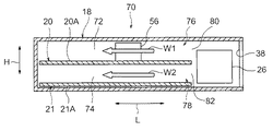
図10に示されるように、上段のプリント基板20は、筐体18の高さ方向の中央部に配置されている。そして、筐体18の内部は、仕切り壁の一例であるプリント基板20によって上下の空間72,74に仕切られている。各空間72,74には、複数の壁部22,24(図8参照)による通風路76,78がそれぞれ形成されている。図8に示されるように、通風路76は、上流領域80、中流領域84、及び、下流領域88を有している。同様に、通風路78も、上流領域82、中流領域86、及び、下流領域90(図9,図10を参照)を有している。
As shown in FIG. 10, the upper printed
図8に示されるように、プリント基板20における正面壁部30側の縁部は、正面壁部30に近接されている。また、一方の壁部22は、プリント基板20Aにおける横幅方向の中央部に配置されており、他方の壁部24は、プリント基板20Aとプリント基板20Bとの間に配置されている。他方の壁部24と正面壁部30との間では、プリント基板20Aとプリント基板20Bとの間に隙間92が設けられている。図10に示されるように、上下の通風路76,78における上流側と下流側との間の中間部同士(上側の中流領域84及び下流領域88の接続部と、下側の中流領域86及び下流領域90の接続部)は、この連通口の一例である隙間92を通じて連通されている。
As shown in FIG. 8, the edge on the
図8に示されるように、送風機26は、プリント基板20に形成された切欠部58に配置されている。送風機26のモータ52が作動してファン54が回転すると、吸気口38から各通風路76,78(図9,図10参照)を通じて排気口40へ流れる冷却風の流れがそれぞれ形成される。つまり、図9,図10に示されるように、上側の通風路76には、冷却風W1が流れ、下側の通風路78には、冷却風W2が流れる。また、図8に示されるように、この第二実施形態においても、送風機26の設置個数は、一つとされている。
As shown in FIG. 8, the
演算素子56は、上段の通風路76のうちの上流領域80に配置されている。演算素子56は、第一実施形態の場合と同様に、壁部22と冷却風W1の流れの方向(矢印L方向)にオーバーラップしている。さらに、この演算素子56は、送風機26に設けられたファン54の中心軸の延長線L1上に配置されている。なお、図9に示されるように、下段の通風路78の上流領域82には、演算素子等の冷却対象物は配置されていない。
The
また、図10に示されるように、上段のプリント基板20A,20Bには、複数の発熱体の一例である高発熱部品94及び低発熱部品96がそれぞれ実装されている。高発熱部品94は、上段の通風路76における中流領域84に配置されており、低発熱部品96は、上段の通風路76における下流領域88に配置されている。高発熱部品94を第一の発熱体の一例とした場合、低発熱部品96は、第二の発熱体の一例である。高発熱部品94は、この高発熱部品94に対する通風路76の下流側に配置された低発熱部品96よりも高い発熱温度を生じるものである。
Further, as shown in FIG. 10, a high
一方、下段のプリント基板21A,21Bには、複数の発熱体の一例である低発熱部品98及び高発熱部品100が実装されている。低発熱部品98は、下段の通風路78における中流領域86に配置されており、高発熱部品100は、下段の通風路78における下流領域90に配置されている。低発熱部品98を第一の発熱体の一例とした場合、高発熱部品100は、第二の発熱体の一例である。低発熱部品98は、この低発熱部品98に対する通風路78の下流側に配置された高発熱部品100よりも低い発熱温度を生じるものである。
On the other hand, a low
次に、第二実施形態に特有の作用及び効果について説明する。 Next, operations and effects unique to the second embodiment will be described.
以上詳述したように、第二実施形態に係る電子機器70(図8〜図10参照)によれば、筐体18の内部は、プリント基板20によって上段の空間72と下段の空間74に仕切られている。そして、各空間72,74には、複数の壁部22,24による通風路76,78がそれぞれ形成されている。従って、上段の通風路76に配置された演算素子56、高発熱部品94、及び、低発熱部品96と、下段の通風路78に配置された低発熱部品98及び高発熱部品100とをそれぞれ冷却することができる。
As described above in detail, according to the electronic device 70 (see FIGS. 8 to 10) according to the second embodiment, the inside of the
また、図10に示されるように、上段の通風路76では、高発熱部品94が低発熱部品96よりも上流側に配置されている。従って、低発熱部品96よりも先に高発熱部品94に冷却風W1を供給することができるので、高発熱部品94を効率良く冷却することができる。また、高発熱部品94を流れることで温度が高くなった冷却風W1は、高発熱部品94よりも冷却を必要としない低発熱部品96に供給される。これにより、上流側の高発熱部品94と下流側の低発熱部品96に発熱状況に応じた温度の冷却風をそれぞれ提供することができ、その結果、高発熱部品94及び低発熱部品96の両方を冷却することができる。
As shown in FIG. 10, the high
また、下段の通風路78では、低発熱部品98が高発熱部品100よりも上流側に配置されている。従って、低発熱部品98を流れることで温度が低いままの冷却風W2を高発熱部品100に供給することができる。これにより、低発熱部品98及び高発熱部品100の両方を冷却することができる。
Further, in the
次に、第二実施形態の変形例について説明する。 Next, a modification of the second embodiment will be described.
上述の第二実施形態においては、送風機26から上段の通風路76に供給される冷却風の流量と、送風機26から下段の通風路78に供給される冷却風の流量とが異なっていても良い。
In the second embodiment described above, the flow rate of the cooling air supplied from the
例えば、図11に示される変形例において、下段の通風路78の入口付近には、送風機26のコネクタ102が配置されている。そして、このコネクタ102によって下段の通風路78への冷却風W2の流れが妨げられることにより、上段の通風路76に供給される冷却風W1の流量は、下段の通風路78に供給される冷却風W2の流量よりも多くなっている。このように構成されていると、演算素子56が配置された上段の通風路76により多くの冷却風が供給されるので、演算素子56に対する冷却性能を向上させることができる。
For example, in the modification shown in FIG. 11, the
また、上述の第二実施形態においては、図12に示されるように、上段の通風路76における下流領域88には、高発熱部品100が配置され、下段の通風路78における下流領域90には、低発熱部品96が配置されても良い。
In the second embodiment described above, as shown in FIG. 12, the high
また、この場合に、下段のプリント基板21Aに設けられた風向制御部材104により、上段の通風路76の下流側(下流領域88)には、下段の通風路78の上流側(中流領域86)から隙間92を通じて冷却風W2が流れても良い。この風向制御部の一例である風向制御部材104は、上段の通風路76における冷却風W1の流れには影響しないので、上段の通風路76では、上流側から下流側(中流領域84から下流領域88)に冷却風W1が流れる。
In this case, the air flow
このように構成されていると、高発熱部品100が配置された上段の通風路76における下流領域88に冷却風W1,W2を集中させることができるので、高発熱部品100に対する冷却性能を向上させることができる。
With this configuration, the cooling air W1 and W2 can be concentrated in the
なお、図13に示されるように、プリント基板20Bに実装された実装部品106により、上段の通風路76の下流側(下流領域88)には、下段の通風路78の上流側(中流領域84)から隙間92を通じて冷却風W2が流れても良い。この風向制御部の一例である実装部品106は、上段の通風路76における冷却風W1の流れには影響しないので、上段の通風路76では、上流側から下流側(中流領域84から下流領域88)に冷却風W1が流れる。
As shown in FIG. 13, the mounting
このように構成されていても、高発熱部品100が配置された上段の通風路76における下流領域88に冷却風W1,W2を集中させることができるので、高発熱部品100に対する冷却性能を向上させることができる。
Even in such a configuration, the cooling air W1 and W2 can be concentrated in the
また、上述の下段のプリント基板21は、図14に示される如く省かれても良い。また、上段の通風路76に配置された高発熱部品94,100は、プリント基板20における一方の実装面(表面)に実装され、下段の通風路78に配置された低発熱部品98,96は、プリント基板20における他方の実装面(裏面)に実装されても良い。
Further, the lower printed
また、上述の図12に示される変形例においては、図15に示されるように、上段のプリント基板20Aに風向制御部の一例である風向制御部材108が設けられても良い。そして、この風向制御部材108により、下段の通風路78の下流側(下流領域90)には、上段の通風路76の上流側(中流領域84)から隙間92を通じて冷却風W1が流れても良い。なお、この場合に、上段の通風路76の上流側から下段の通風路78の下流側に流れる冷却風W1が通過する連通口と、下段の通風路78の上流側から上段の通風路76の下流側に流れる冷却風W2が通過する連通口とが別々にプリント基板20に形成されていても良い。なお、図12〜図15に示される変形例において、上段の通風路76は、一の通風路の一例であり、下段の通風路78は、他の通風路の一例である。
In the modification shown in FIG. 12 described above, as shown in FIG. 15, a wind
また、図16に示されるように、上段の通風路76における下流領域88には、拡張ユニット110が配置され、下段の通風路78における下流領域90には、複数の電源ユニット112が配置されても良い。この拡張ユニット110及び複数の電源ユニット112は、発熱体の一例である。また、複数の電源ユニット112は、拡張ユニット110よりも高い発熱温度を生じるものである。
Further, as shown in FIG. 16, the
この図16に示される変形例では、上段の通風路76における下流領域88の全体を占めるように拡張ユニット110が配置されている。従って、上段の通風路76における上流側から下流側への冷却風W1の流れは、拡張ユニット110により阻害される。これにより、下段の通風路78の下流側(下流領域90)には、上段の通風路76の上流側(中流領域84)から隙間92を通じて冷却風W1が流れる。また、この風向制御部の一例である拡張ユニット110は、下段の通風路78における冷却風W2の流れには影響しないので、下段の通風路78では、上流側から下流側(中流領域86から下流領域90)に冷却風W2が流れる。
In the modification shown in FIG. 16, the
このように構成されていると、複数の電源ユニット112が配置された下段の通風路78における下流領域90に冷却風W1,W2を集中させることができるので、複数の電源ユニット112に対する冷却性能を向上させることができる。
With this configuration, the cooling air W1 and W2 can be concentrated in the
また、この図16に示される変形例においては、図17に示されるように、拡張ユニット110の代わりに、低発熱部品96が配置されても良く、また、電源ユニット112の代わりに、高発熱部品100が配置されても良い。また、プリント基板20Aに風向制御部材114が実装されることで、下段の通風路78における下流領域90に冷却風W1,W2が集中されても良い。さらに、高発熱部品94及び低発熱部品96は、プリント基板20における一方の実装面(表面)に実装され、低発熱部品98及び高発熱部品100は、プリント基板20における他方の実装面(裏面)に実装されても良い。なお、図16,図17に示される変形例において、下段の通風路78は、一の通風路の一例であり、上段の通風路76は、他の通風路の一例である。
In the modification shown in FIG. 16, as shown in FIG. 17, a low
また、上述の第二実施形態においては、プリント基板20の代わりに仕切り壁が設けられても良い。また、この仕切り壁には、上述の上下の通風路76,78における上流側と下流側との間の中間部同士を連通する連通口が形成されていても良い。
In the second embodiment described above, a partition wall may be provided instead of the printed
また、筐体18の内部には、筐体18の高さ方向に対向する複数の仕切り壁が設けられ、筐体18の内部が複数の空間(三つ以上の空間)に仕切られていても良い。また、筐体18の内部には、壁部が三つ以上設けられ、通風路76,78が四つ以上の領域に分割されても良い。
In addition, a plurality of partition walls facing the height direction of the
また、上述の第二実施形態の変形例は、適宜組み合わされて実施されても良い。また、上述の第二実施形態の変形例は、第一実施形態及びその変形例と適宜組み合わされて実施されても良い。 The modifications of the second embodiment described above may be implemented in appropriate combination. The modification of the second embodiment described above may be implemented in combination with the first embodiment and the modification as appropriate.
以上、本願の開示する技術の一態様について説明したが、本願の開示する技術は、上記に限定されるものでなく、上記以外にも、その主旨を逸脱しない範囲内において種々変形して実施可能であることは勿論である。 Although one aspect of the technology disclosed in the present application has been described above, the technology disclosed in the present application is not limited to the above, and various modifications can be made without departing from the gist of the present invention. Of course.
なお、上述の本願の開示する技術の一態様に関し、更に以下の付記を開示する。 In addition, the following additional remarks are disclosed regarding the one aspect | mode of the technique which the above-mentioned this application discloses.
(付記1)
吸気口及び排気口を有する筐体と、
それぞれ前記吸気口の開口方向に沿って延び、前記筐体の内部に蛇行する通風路を形成する複数の壁部と、
前記吸気口から前記通風路を通じて前記排気口へ流れる冷却風の流れを形成する送風機と、
を備えた電子機器。
(付記2)
前記通風路には、冷却対象物が配置され、
前記冷却対象物は、前記複数の壁部のうち一の壁部と前記冷却風の流れの方向にオーバーラップしている、
付記1に記載の電子機器。
(付記3)
前記送風機は、前記吸気口の開口方向に前記吸気口と対向して配置され、
前記冷却対象物は、前記送風機に設けられたファンの中心軸の延長線上に配置されている、
付記2に記載の電子機器。
(付記4)
前記筐体の内部には、プリント基板が収容され、
前記筐体は、前記吸気口の開口方向に対向する一対の縦壁部を有し、
前記複数の壁部のうち少なくとも一の壁部は、前記プリント基板に実装された電子部品の基板であり、
前記電子部品の前記基板は、前記吸気口の開口方向に前記一対の縦壁部と離間している、
付記1〜付記3のいずれか一項に記載の電子機器。
(付記5)
前記電子部品は、メモリモジュール又は電圧変換器である、
付記4に記載の電子機器。
(付記6)
前記送風機の設置個数は、一つである、
付記1〜付記5のいずれか一項に記載の電子機器。
(付記7)
前記筐体の内部には、プリント基板が収容され、
前記プリント基板には、切欠部が形成され、
前記送風機は、前記切欠部に配置されている、
付記1〜付記6のいずれか一項に記載の電子機器。
(付記8)
前記通風路には、冷却対象物が配置され、
前記冷却対象物には、前記冷却風の流れの方向に沿って延びる冷却フィンが設けられている、
付記1〜付記7のいずれか一項に記載の電子機器。
(付記9)
前記通風路には、複数の発熱体が配置され、
前記複数の発熱体のうち前記通風路の上流側に配置された第一の発熱体は、前記複数の発熱体のうち前記第一の発熱体に対する前記通風路の下流側に配置された第二の発熱体よりも高い発熱温度を生じるものである、
付記1〜付記8のいずれか一項に記載の電子機器。
(付記10)
前記通風路には、複数の発熱体が配置され、
前記複数の発熱体のうち前記通風路の上流側に配置された第一の発熱体は、前記複数の発熱体のうち前記第一の発熱体に対する前記通風路の下流側に配置された第二の発熱体よりも低い発熱温度を生じるものである、
付記1〜付記8のいずれか一項に記載の電子機器。
(付記11)
前記筐体の内部は、前記筐体の内部に収容された仕切り壁によって複数の空間に仕切られ、
前記複数の空間には、前記通風路がそれぞれ形成されている、
付記1〜付記8のいずれか一項に記載の電子機器。
(付記12)
前記仕切り壁には、複数の前記通風路における上流側と下流側との間の中間部同士を連通する連通口が形成され、
前記筐体の内部には、複数の前記通風路のうち一の通風路の下流側に他の通風路の上流側から前記連通口を通じて冷却風を流させる風向制御部が設けられている、
付記11に記載の電子機器。
(付記13)
複数の前記通風路には、複数の発熱体がそれぞれ配置され、
前記複数の発熱体のうち前記一の通風路の下流側に配置された一の発熱体は、前記複数の発熱体のうち前記他の通風路の下流側に配置された他の発熱体よりも高い発熱温度を生じるものである、
付記12に記載の電子機器。
(付記14)
前記複数の発熱体のうち前記一の通風路の上流側に配置された発熱体は、前記他の発熱体よりも高い発熱温度を生じるものであり、
前記風向制御部は、前記一の通風路の上流側から下流側に冷却風を流させる、
付記13に記載の電子機器。
(付記15)
前記複数の発熱体のうち前記一の通風路の上流側に配置された発熱体は、前記他の発熱体よりも高い発熱温度を生じるものであり、
前記風向制御部は、前記一の通風路の上流側から前記他の通風路の下流側に前記連通口を通じて冷却風を流させる、
付記13に記載の電子機器。
(付記16)
前記複数の発熱体のうち前記一の通風路の上流側に配置された発熱体は、前記一の発熱体よりも低い発熱温度を生じるものであり、
前記風向制御部は、前記一の通風路の上流側から下流側に冷却風を流させる、
付記13に記載の電子機器。
(付記17)
前記仕切り壁は、プリント基板であり、
前記プリント基板の両側の実装面には、前記一の通風路に配置された前記発熱体と、前記他の通風路に配置された前記発熱体とがそれぞれ実装されている、
付記11〜付記16のいずれか一項に記載の電子機器。
(Appendix 1)
A housing having an air inlet and an air outlet;
A plurality of wall portions each extending along the opening direction of the intake port and forming a meandering air passage inside the housing;
A blower that forms a flow of cooling air flowing from the intake port to the exhaust port through the ventilation path;
With electronic equipment.
(Appendix 2)
An object to be cooled is disposed in the ventilation path,
The object to be cooled overlaps one of the plurality of wall portions in the direction of the flow of the cooling air,
The electronic device according to attachment 1.
(Appendix 3)
The blower is disposed to face the intake port in the opening direction of the intake port,
The object to be cooled is disposed on an extension line of a central axis of a fan provided in the blower.
The electronic device according to
(Appendix 4)
A printed circuit board is accommodated in the housing,
The housing has a pair of vertical wall portions facing the opening direction of the intake port,
At least one wall portion of the plurality of wall portions is a board of an electronic component mounted on the printed board,
The substrate of the electronic component is spaced apart from the pair of vertical wall portions in the opening direction of the air inlet;
The electronic device according to any one of appendix 1 to appendix 3.
(Appendix 5)
The electronic component is a memory module or a voltage converter.
The electronic device according to attachment 4.
(Appendix 6)
The number of fans installed is one,
The electronic device according to any one of appendix 1 to appendix 5.
(Appendix 7)
A printed circuit board is accommodated in the housing,
The printed circuit board is formed with a notch,
The blower is disposed in the notch,
The electronic device according to any one of appendix 1 to appendix 6.
(Appendix 8)
An object to be cooled is disposed in the ventilation path,
The cooling object is provided with cooling fins extending along the direction of the flow of the cooling air.
The electronic device according to any one of appendix 1 to appendix 7.
(Appendix 9)
A plurality of heating elements are arranged in the ventilation path,
A first heating element disposed on the upstream side of the ventilation path among the plurality of heating elements is a second heating element disposed on the downstream side of the ventilation path with respect to the first heating element among the plurality of heating elements. Which produces a higher heating temperature than the heating element of
The electronic device according to any one of appendix 1 to appendix 8.
(Appendix 10)
A plurality of heating elements are arranged in the ventilation path,
A first heating element disposed on the upstream side of the ventilation path among the plurality of heating elements is a second heating element disposed on the downstream side of the ventilation path with respect to the first heating element among the plurality of heating elements. Which produces a lower heating temperature than the heating element of
The electronic device according to any one of appendix 1 to appendix 8.
(Appendix 11)
The interior of the housing is partitioned into a plurality of spaces by a partition wall housed in the housing,
The ventilation paths are respectively formed in the plurality of spaces.
The electronic device according to any one of appendix 1 to appendix 8.
(Appendix 12)
The partition wall is formed with a communication port that communicates intermediate portions between the upstream side and the downstream side of the plurality of ventilation paths,
Inside the casing, a wind direction control unit is provided that allows cooling air to flow through the communication port from the upstream side of another ventilation path to the downstream side of one ventilation path among the plurality of ventilation paths.
The electronic device according to attachment 11.
(Appendix 13)
A plurality of heating elements are respectively disposed in the plurality of ventilation paths,
One heating element disposed on the downstream side of the one ventilation path among the plurality of heating elements is more than the other heating element disposed on the downstream side of the other ventilation path among the plurality of heating elements. Which produces a high exothermic temperature,
The electronic device according to
(Appendix 14)
Of the plurality of heating elements, the heating element disposed on the upstream side of the one ventilation path generates a higher heating temperature than the other heating element,
The wind direction control unit causes cooling air to flow from the upstream side to the downstream side of the one ventilation path,
The electronic device according to attachment 13.
(Appendix 15)
Of the plurality of heating elements, the heating element disposed on the upstream side of the one ventilation path generates a higher heating temperature than the other heating element,
The air direction control unit causes cooling air to flow through the communication port from the upstream side of the one air passage to the downstream side of the other air passage.
The electronic device according to attachment 13.
(Appendix 16)
Of the plurality of heating elements, the heating element disposed on the upstream side of the one ventilation path generates a lower heating temperature than the one heating element,
The wind direction control unit causes cooling air to flow from the upstream side to the downstream side of the one ventilation path,
The electronic device according to attachment 13.
(Appendix 17)
The partition wall is a printed circuit board;
The heating elements arranged in the one ventilation path and the heating elements arranged in the other ventilation path are respectively mounted on the mounting surfaces on both sides of the printed circuit board.
The electronic device according to any one of appendices 11 to 16.
10,70 電子機器
18 筐体
20 プリント基板(仕切り壁の一例)
22,24 複数の壁部
26 送風機
30 正面壁部(縦壁部の一例)
32 背面壁部(縦壁部の一例)
38 吸気口
40 排気口
44 通風路
54 ファン
56 演算素子(冷却対象物の一例)
58 切欠部
60 メモリモジュール(電子部品の一例)
62 基板
64 冷却フィン
72,74 複数の空間
76,78 複数の通風路
92 隙間(連通口の一例)
94,100 高発熱部品(発熱体の一例)
96,98 低発熱部品(発熱体の一例)
104,108,114 風向制御部材(風向制御部の一例)
106 実装部品(風向制御部の一例)
110 拡張ユニット(発熱体及び風向制御部の一例)
112 電源ユニット(発熱体の一例)
10, 70
22, 24
32 Back wall (an example of a vertical wall)
38
58
62
94,100 High heat generation parts (example of heating element)
96,98 Low heat generation parts (example of heating element)
104, 108, 114 Wind direction control member (an example of a wind direction control unit)
106 Mounted parts (example of wind direction control unit)
110 Expansion unit (example of heating element and wind direction control unit)
112 Power supply unit (example of heating element)
Claims (8)
それぞれ前記吸気口の開口方向に沿って延び、前記筐体の内部に蛇行する通風路を形成する複数の壁部と、
前記吸気口から前記通風路を通じて前記排気口へ流れる冷却風の流れを形成する送風機と、
を備え、
前記筐体の内部には、プリント基板が収容され、
前記筐体は、前記吸気口の開口方向に対向する一対の縦壁部を有し、
前記複数の壁部のうち少なくとも一の壁部は、前記プリント基板に実装された電子部品の基板であり、
前記電子部品の前記基板は、前記吸気口の開口方向に前記一対の縦壁部と離間している、
電子機器。 A housing having an air inlet and an air outlet;
A plurality of wall portions each extending along the opening direction of the intake port and forming a meandering air passage inside the housing;
A blower that forms a flow of cooling air flowing from the intake port to the exhaust port through the ventilation path;
Equipped with a,
A printed circuit board is accommodated in the housing,
The housing has a pair of vertical wall portions facing the opening direction of the intake port,
At least one wall portion of the plurality of wall portions is a board of an electronic component mounted on the printed board,
The substrate of the electronic component is spaced apart from the pair of vertical wall portions in the opening direction of the air inlet;
Electronics.
前記冷却対象物は、前記複数の壁部のうち一の壁部と前記冷却風の流れの方向にオーバーラップしている、
請求項1に記載の電子機器。 An object to be cooled is disposed in the ventilation path,
The object to be cooled overlaps one of the plurality of wall portions in the direction of the flow of the cooling air,
The electronic device according to claim 1.
前記冷却対象物は、前記送風機に設けられたファンの中心軸の延長線上に配置されている、
請求項2に記載の電子機器。 The blower is disposed to face the intake port in the opening direction of the intake port,
The object to be cooled is disposed on an extension line of a central axis of a fan provided in the blower.
The electronic device according to claim 2.
前記複数の空間には、前記通風路がそれぞれ形成され、
前記仕切り壁には、複数の前記通風路における上流側と下流側との間の中間部同士を連通する連通口が形成され、
前記筐体の内部には、複数の前記通風路のうち一の通風路の下流側に他の通風路の上流側から前記連通口を通じて冷却風を流させる風向制御部が設けられている、
請求項1〜請求項3のいずれか一項に記載の電子機器。 The interior of the housing is partitioned into a plurality of spaces by a partition wall housed in the housing,
The ventilation paths are formed in the plurality of spaces, respectively.
The partition wall is formed with a communication port that communicates intermediate portions between the upstream side and the downstream side of the plurality of ventilation paths,
Inside the casing, a wind direction control unit is provided that allows cooling air to flow through the communication port from the upstream side of another ventilation path to the downstream side of one ventilation path among the plurality of ventilation paths.
The electronic device as described in any one of Claims 1-3 .
前記複数の発熱体のうち前記一の通風路の下流側に配置された一の発熱体は、前記複数の発熱体のうち前記他の通風路の下流側に配置された他の発熱体よりも高い発熱温度を生じるものである、
請求項4に記載の電子機器。 A plurality of heating elements are respectively disposed in the plurality of ventilation paths,
One heating element disposed on the downstream side of the one ventilation path among the plurality of heating elements is more than the other heating element disposed on the downstream side of the other ventilation path among the plurality of heating elements. Which produces a high exothermic temperature,
The electronic device according to claim 4 .
前記風向制御部は、前記一の通風路の上流側から下流側に冷却風を流させる、
請求項5に記載の電子機器。 Of the plurality of heating elements, the heating element disposed on the upstream side of the one ventilation path generates a higher heating temperature than the other heating element,
The wind direction control unit causes cooling air to flow from the upstream side to the downstream side of the one ventilation path,
The electronic device according to claim 5.
前記風向制御部は、前記一の通風路の上流側から前記他の通風路の下流側に前記連通口を通じて冷却風を流させる、
請求項5に記載の電子機器。 Of the plurality of heating elements, the heating element disposed on the upstream side of the one ventilation path generates a higher heating temperature than the other heating element,
The air direction control unit causes cooling air to flow through the communication port from the upstream side of the one air passage to the downstream side of the other air passage.
The electronic device according to claim 5 .
前記風向制御部は、前記一の通風路の上流側から下流側に冷却風を流させる、
請求項5に記載の電子機器。 Of the plurality of heating elements, the heating element disposed on the upstream side of the one ventilation path generates a lower heating temperature than the one heating element,
The wind direction control unit causes cooling air to flow from the upstream side to the downstream side of the one ventilation path,
The electronic device according to claim 5 .
Priority Applications (2)
| Application Number | Priority Date | Filing Date | Title |
|---|---|---|---|
| JP2013104277A JP6225477B2 (en) | 2013-05-16 | 2013-05-16 | Electronics |
| US14/261,529 US20140340846A1 (en) | 2013-05-16 | 2014-04-25 | Electronic apparatus |
Applications Claiming Priority (1)
| Application Number | Priority Date | Filing Date | Title |
|---|---|---|---|
| JP2013104277A JP6225477B2 (en) | 2013-05-16 | 2013-05-16 | Electronics |
Publications (2)
| Publication Number | Publication Date |
|---|---|
| JP2014225573A JP2014225573A (en) | 2014-12-04 |
| JP6225477B2 true JP6225477B2 (en) | 2017-11-08 |
Family
ID=51895617
Family Applications (1)
| Application Number | Title | Priority Date | Filing Date |
|---|---|---|---|
| JP2013104277A Active JP6225477B2 (en) | 2013-05-16 | 2013-05-16 | Electronics |
Country Status (2)
| Country | Link |
|---|---|
| US (1) | US20140340846A1 (en) |
| JP (1) | JP6225477B2 (en) |
Families Citing this family (10)
| Publication number | Priority date | Publication date | Assignee | Title |
|---|---|---|---|---|
| WO2012083698A1 (en) * | 2011-08-01 | 2012-06-28 | 华为技术有限公司 | Ventilation denoising device and ventilation denoising system |
| US9363927B2 (en) * | 2014-09-12 | 2016-06-07 | Lanner Electronic Inc. | Electrical signal computing module capable of accommodating printed circuit board |
| JP6485193B2 (en) * | 2015-04-30 | 2019-03-20 | 富士通株式会社 | Electronic device storage device and relay device |
| US10591331B2 (en) | 2015-09-30 | 2020-03-17 | Hitachi Automotive Systems, Ltd. | Intake temperature detection device and maximum heat generating amount components mounted on a single circuit board |
| US10506742B2 (en) | 2015-12-02 | 2019-12-10 | Nec Network And Sensor Systems, Ltd. | Electronic component housing apparatus and electronic device |
| JP2018036531A (en) * | 2016-08-31 | 2018-03-08 | 京セラドキュメントソリューションズ株式会社 | Image forming apparatus |
| CN107574401B (en) * | 2017-09-19 | 2019-06-25 | 江阴恩特莱特镀膜科技有限公司 | A kind of air cooling equipment for plasma spraying target |
| US10927732B2 (en) * | 2018-03-28 | 2021-02-23 | Cummins Power Generation Ip, Inc. | Low noise enclosure |
| TWI674058B (en) * | 2018-05-25 | 2019-10-01 | 廣達電腦股份有限公司 | Ducting arrangement in computing device |
| JP7253896B2 (en) * | 2018-11-02 | 2023-04-07 | 三菱重工サーマルシステムズ株式会社 | Electrical component module and chilling unit |
Family Cites Families (21)
| Publication number | Priority date | Publication date | Assignee | Title |
|---|---|---|---|---|
| IT1039770B (en) * | 1974-07-26 | 1979-12-10 | Piller Kg Anton | ROTATING FREQUENCY CONVERTER |
| JPS5685997U (en) * | 1979-12-07 | 1981-07-10 | ||
| US5121290A (en) * | 1990-06-25 | 1992-06-09 | At&T Bell Laboratories | Circuit pack cooling using perforations |
| JP3663706B2 (en) * | 1995-01-27 | 2005-06-22 | 株式会社日立製作所 | Personal computer |
| US6034870A (en) * | 1999-01-27 | 2000-03-07 | Sun Microsystems, Inc. | Computer system having a highly efficient forced air cooling subsystem |
| US6144556A (en) * | 1999-03-30 | 2000-11-07 | Lanclos; Kenneth W. | Heat dissipating housing for electronic components |
| JP2002118386A (en) * | 2000-10-05 | 2002-04-19 | Hitachi Ltd | Electronic apparatus |
| JP3784674B2 (en) * | 2001-07-31 | 2006-06-14 | 三菱電機株式会社 | Electronic equipment |
| US6704196B1 (en) * | 2002-07-25 | 2004-03-09 | Allied Systems Design, Inc. | Flow-through cooling in-the-round system |
| US7286348B2 (en) * | 2004-11-16 | 2007-10-23 | Hewlett-Packard Development Company, L.P. | Housing assembly for a computer |
| US7218517B2 (en) * | 2004-12-07 | 2007-05-15 | International Business Machines Corporation | Cooling apparatus for vertically stacked printed circuit boards |
| US7403385B2 (en) * | 2006-03-06 | 2008-07-22 | Cisco Technology, Inc. | Efficient airflow management |
| JP5034316B2 (en) * | 2006-05-22 | 2012-09-26 | トヨタ自動車株式会社 | Power supply |
| JP5030631B2 (en) * | 2007-03-22 | 2012-09-19 | 富士通株式会社 | Cooling system for information equipment |
| JP5011016B2 (en) * | 2007-07-30 | 2012-08-29 | 株式会社日立産機システム | Power converter |
| JP5062014B2 (en) * | 2008-04-17 | 2012-10-31 | セイコーエプソン株式会社 | Electronic circuit module, power supply device, projector |
| US7843685B2 (en) * | 2008-04-22 | 2010-11-30 | International Business Machines Corporation | Duct system for high power adapter cards |
| JP5471644B2 (en) * | 2010-03-15 | 2014-04-16 | 富士通株式会社 | Information equipment |
| US9167726B2 (en) * | 2011-11-17 | 2015-10-20 | Cray Inc. | Transverse cooling system and method |
| US9185828B2 (en) * | 2011-11-17 | 2015-11-10 | Cray Inc. | Rack mounted electronics having connectors with heat cooling fingers |
| KR102094887B1 (en) * | 2013-07-08 | 2020-03-30 | 엘지전자 주식회사 | Digital signage and driving method therof |
-
2013
- 2013-05-16 JP JP2013104277A patent/JP6225477B2/en active Active
-
2014
- 2014-04-25 US US14/261,529 patent/US20140340846A1/en not_active Abandoned
Also Published As
| Publication number | Publication date |
|---|---|
| JP2014225573A (en) | 2014-12-04 |
| US20140340846A1 (en) | 2014-11-20 |
Similar Documents
| Publication | Publication Date | Title |
|---|---|---|
| JP6225477B2 (en) | Electronics | |
| US9861005B2 (en) | Cooling system for a hand-held electronic device | |
| EP2106206B1 (en) | Cooling device for accomodated printed circuit board in a chassis | |
| JP4994503B2 (en) | Arithmetic processing unit | |
| US9974207B2 (en) | Electronic apparatus | |
| JP5927911B2 (en) | COOLING UNIT, COOLING UNIT CASES, AND ELECTRONIC DEVICE | |
| US20120201001A1 (en) | Electronic device and complex electronic device | |
| JP5471644B2 (en) | Information equipment | |
| JP5596389B2 (en) | Power supply | |
| TW201443345A (en) | Electronic device and air duct of the same | |
| JP4558627B2 (en) | Electronic device casing and electronic device | |
| US20160360641A1 (en) | Electronic device | |
| JP2007123641A5 (en) | ||
| JP2011204715A (en) | Radiation unit and electronic device using the same | |
| JP5412815B2 (en) | Cooling jacket, cooling unit, cooling system and electronic equipment | |
| JP6615630B2 (en) | Electrical equipment | |
| TW201422135A (en) | Electronic device | |
| JP2008047658A (en) | Cooling structure of electronic equipment | |
| JP2007329253A (en) | Cooling structure of electronic apparatus | |
| JP4639846B2 (en) | Housing cooling structure | |
| TWI511655B (en) | Channel diversion device and related heat dissipating system | |
| JP2014143232A (en) | On-vehicle controller | |
| JP6621153B1 (en) | Server device and cooling method | |
| JP2019040968A (en) | Electric device | |
| JP2009164178A (en) | Heat radiator of electronic equipment |
Legal Events
| Date | Code | Title | Description |
|---|---|---|---|
| A621 | Written request for application examination |
Free format text: JAPANESE INTERMEDIATE CODE: A621 Effective date: 20160226 |
|
| A977 | Report on retrieval |
Free format text: JAPANESE INTERMEDIATE CODE: A971007 Effective date: 20161221 |
|
| A131 | Notification of reasons for refusal |
Free format text: JAPANESE INTERMEDIATE CODE: A131 Effective date: 20170207 |
|
| A521 | Written amendment |
Free format text: JAPANESE INTERMEDIATE CODE: A523 Effective date: 20170302 |
|
| TRDD | Decision of grant or rejection written | ||
| A01 | Written decision to grant a patent or to grant a registration (utility model) |
Free format text: JAPANESE INTERMEDIATE CODE: A01 Effective date: 20170912 |
|
| A61 | First payment of annual fees (during grant procedure) |
Free format text: JAPANESE INTERMEDIATE CODE: A61 Effective date: 20170925 |
|
| R150 | Certificate of patent or registration of utility model |
Ref document number: 6225477 Country of ref document: JP Free format text: JAPANESE INTERMEDIATE CODE: R150 |