JP6007925B2 - Substrate cleaning apparatus, substrate cleaning method, and storage medium - Google Patents
Substrate cleaning apparatus, substrate cleaning method, and storage medium Download PDFInfo
- Publication number
- JP6007925B2 JP6007925B2 JP2014014864A JP2014014864A JP6007925B2 JP 6007925 B2 JP6007925 B2 JP 6007925B2 JP 2014014864 A JP2014014864 A JP 2014014864A JP 2014014864 A JP2014014864 A JP 2014014864A JP 6007925 B2 JP6007925 B2 JP 6007925B2
- Authority
- JP
- Japan
- Prior art keywords
- nozzle
- cleaning liquid
- substrate
- gas
- cleaning
- Prior art date
- Legal status (The legal status is an assumption and is not a legal conclusion. Google has not performed a legal analysis and makes no representation as to the accuracy of the status listed.)
- Active
Links
Images


Classifications
-
- H—ELECTRICITY
- H01—ELECTRIC ELEMENTS
- H01L—SEMICONDUCTOR DEVICES NOT COVERED BY CLASS H10
- H01L21/00—Processes or apparatus adapted for the manufacture or treatment of semiconductor or solid state devices or of parts thereof
- H01L21/67—Apparatus specially adapted for handling semiconductor or electric solid state devices during manufacture or treatment thereof; Apparatus specially adapted for handling wafers during manufacture or treatment of semiconductor or electric solid state devices or components ; Apparatus not specifically provided for elsewhere
- H01L21/67005—Apparatus not specifically provided for elsewhere
- H01L21/67011—Apparatus for manufacture or treatment
- H01L21/67017—Apparatus for fluid treatment
- H01L21/67028—Apparatus for fluid treatment for cleaning followed by drying, rinsing, stripping, blasting or the like
- H01L21/6704—Apparatus for fluid treatment for cleaning followed by drying, rinsing, stripping, blasting or the like for wet cleaning or washing
- H01L21/67051—Apparatus for fluid treatment for cleaning followed by drying, rinsing, stripping, blasting or the like for wet cleaning or washing using mainly spraying means, e.g. nozzles
Description
本発明は、基板を回転させながら基板の表面を洗浄液により洗浄する技術分野に関する。 The present invention relates to a technical field of cleaning a surface of a substrate with a cleaning liquid while rotating the substrate.
半導体ウエハ等の基板に対してレジストパターンを形成するための露光処理として、基板の表面に液体を存在させて露光を行う液浸露光が知られている。液浸露光に用いられるレジストは、基板の周端や裏面への回り込みを抑えるために撥水性の高いものが用いられている。露光後の基板に対して行われる現像処理においては、現像液を基板に供給して例えば露光部分を溶解させ、次いで基板を回転させながら洗浄液例えば純水を当該基板に供給して溶解生成物を基板の表面から洗い流すようにしている。具体的には、洗浄液ノズルから洗浄液を吐出させながら当該洗浄液ノズルを基板の中心部から基板の周縁部に向かってスキャンする手法が知られている。 As exposure processing for forming a resist pattern on a substrate such as a semiconductor wafer, immersion exposure is known in which exposure is performed in the presence of a liquid on the surface of the substrate. As the resist used for the immersion exposure, a resist having high water repellency is used in order to suppress wraparound to the peripheral edge or back surface of the substrate. In the development processing performed on the substrate after exposure, a developer is supplied to the substrate to dissolve, for example, the exposed portion, and then a cleaning solution such as pure water is supplied to the substrate while rotating the substrate to thereby dissolve the dissolved product. The substrate is washed away from the surface. Specifically, a technique is known in which the cleaning liquid nozzle is scanned from the center of the substrate toward the peripheral edge of the substrate while discharging the cleaning liquid from the cleaning liquid nozzle.
しかしながらレジストが形成されている下地膜の撥水性は低い(接触角が小さい)ことから、撥水性の高い(接触角が大きい)レジストが用いられた露光後の基板においては、露光部分と未露光部分との接触角の差異が大きい。このため、現像液を供給した後に洗浄液を供給すると、液千切れが発生して基板の表面に液滴が残りやすくなる。この液滴が乾燥すると残渣になり、半導体デバイスの歩留まりの低下の要因となる。 However, since the water repellency of the base film on which the resist is formed is low (the contact angle is small), the exposed portion and the unexposed portion of the exposed substrate using the resist having a high water repellency (a large contact angle) are used. The difference in contact angle with the part is large. For this reason, if the cleaning liquid is supplied after the developer is supplied, the liquid breaks off and droplets are likely to remain on the surface of the substrate. When these droplets are dried, they become residues and cause a decrease in the yield of semiconductor devices.
下地膜としては有機材からなる反射防止膜が主流であったが、最近において接触角がより小さい無機材からなる反射防止膜が検討されており、この場合には露光部分と未露光部分との接触角の差異がより一層大きくなり、残渣が更に発生しやすくなる。
露光部分と未露光部分との接触角の差異が大きい基板に対して上述の洗浄を行う場合には、洗浄液ノズルのスキャン速度を遅くすることが有効であるが、装置のスループットの低下の要因になる。特に塗布、現像装置においては、市場にて1時間あたり200枚以上もの処理が要求されていることから、高いスループットを維持しながら残渣の低減を図ることのできる手法が望まれている。
As the base film, an antireflection film made of an organic material has been the mainstream, but recently, an antireflection film made of an inorganic material having a smaller contact angle has been studied. The difference in contact angle is further increased, and residues are more likely to be generated.
When the above-described cleaning is performed on a substrate having a large contact angle difference between an exposed portion and an unexposed portion, it is effective to reduce the scanning speed of the cleaning liquid nozzle, but this causes a decrease in the throughput of the apparatus. Become. In particular, since coating and developing apparatuses require processing of 200 sheets or more per hour in the market, a technique capable of reducing residues while maintaining high throughput is desired.
これを解決する洗浄方法として、特許文献1には、基板に洗浄液を吐出した後、ウエハの中心部に窒素ガスを吐出して乾燥領域のコアを形成する。その後洗浄液の吐出位置をウエハの外方側に移動させながら、ガスの吐出位置も移動させて、乾燥領域を外方側に広げる技術が記載されており、ガスの吐出位置を移動させる際に、ガスノズルの移動速度を基板の周縁側の領域において速くする技術が記載されている。特許文献2には、基板の洗浄を行うにあたり、基板に向けて吐出する液体及び気体の混合体に含まれる気体の流量を基板の周縁部に近づくにしたがって、変更する技術が記載されている。また特許文献3には、基板の周縁に近づくにつれて、ガスの噴射角を大きくして、気体の圧力を弱め、均一に乾燥する技術が記載されている。特許文献4には、一のノズルから基板のある領域に向けてガスを吐出した後、同一の領域に向けて他のノズルからガスを吐出する技術が記載されている。今後は、より一層の洗浄の精度が求められることが予想され、残渣の低減を図るためには、更なる改良が要請される。
As a cleaning method for solving this problem,
本発明は、このような事情の下になされたものであり、その目的は、基板を回転させながら、基板の表面を洗浄液により洗浄するにあたり、洗浄処理後の液滴の残りを抑制し、残渣を低減する技術を提供することにある。 The present invention has been made under such circumstances. The purpose of the present invention is to suppress the remaining of the droplets after the cleaning process when cleaning the surface of the substrate with the cleaning liquid while rotating the substrate. It is to provide a technique for reducing the above.
本発明の基板洗浄装置は、基板を回転させながら洗浄液及びガスを用いて基板を洗浄する装置において、
基板を水平に保持する基板保持部と、
前記基板保持部を鉛直軸周りに回転させる回転機構と、
前記基板保持部に保持された基板に各々洗浄液を供給するための第1の洗浄液ノズル及び第2の洗浄液ノズルと、
前記基板保持部に保持された基板にガスを吐出する基板の中心部にガスを吐出するときに用いられる第1のガスノズルと、
前記第1のガスノズルの移動軌跡から外れる位置に設けられた第2のガスノズルと、
前記第1の洗浄液ノズル、第2の洗浄液ノズル、第1のガスノズル及び第2のガスノズルを移動させるためのノズル移動部と、
前記第1の洗浄液ノズルから洗浄液を基板の中心部に吐出するステップと、次いで前記洗浄液の吐出位置を前記基板の中心部から周縁側に移動させた後、前記第1のガスノズルからガスを当該中心部に吐出するステップと、続いて第1の洗浄液ノズル及び第1のガスノズルから夫々洗浄液及びガスの吐出を行いながら前記第1の洗浄液ノズル及び前記第1のガスノズルの各吐出位置を基板の周縁側に向けて移動させるステップと、次に前記第1の洗浄液ノズルから第2の洗浄液ノズルに洗浄液の吐出を切替えると共に、前記第1のガスノズルから第2のガスノズルにガスの吐出を切替え、第2の洗浄液ノズルからの洗浄液の吐出及び第2のガスノズルからのガスの吐出を行いながら当該第2の洗浄液ノズル及び当該第2のガスノズルの各吐出位置を基板の周縁側に向けて移動させるステップと、を実行するように制御信号を出力する制御部と、を備え、
前記第2の洗浄液ノズルは、吐出位置が第1の洗浄液ノズルの吐出位置の移動軌跡から外れる位置に設定され、
第2の洗浄液ノズル及び第2のガスノズルの各吐出位置から基板の中心部までの距離を、夫々d2及びd3とすると、第2の洗浄液ノズルから洗浄液を吐出しているときには、d3<d2であり、かつ第2の洗浄液ノズルが基板の周縁側に移動するにつれて、d2とd3との差が徐々に小さくなるように構成されていることを特徴とする。
The substrate cleaning apparatus of the present invention is an apparatus for cleaning a substrate using a cleaning liquid and a gas while rotating the substrate.
A substrate holder for horizontally holding the substrate;
A rotation mechanism for rotating the substrate holder around a vertical axis;
A first cleaning liquid nozzle and a second cleaning liquid nozzle for supplying a cleaning liquid to each of the substrates held by the substrate holder;
A first gas nozzle that is used when gas is discharged to the center of the substrate that discharges gas to the substrate held by the substrate holder ;
A second gas nozzle provided at a position deviating from the movement locus of the first gas nozzle;
A nozzle moving unit for moving the first cleaning liquid nozzle, the second cleaning liquid nozzle , the first gas nozzle, and the second gas nozzle;
A step of discharging the cleaning liquid from the first cleaning liquid nozzle to the center of the substrate; and then, after the discharge position of the cleaning liquid is moved from the center of the substrate to the peripheral side, the gas is discharged from the first gas nozzle to the center. And discharging each of the first cleaning liquid nozzle and the first gas nozzle to the peripheral side of the substrate while discharging the cleaning liquid and the gas from the first cleaning liquid nozzle and the first gas nozzle, respectively. switching and moving in, then switches the discharge of the cleaning liquid to the second cleaning liquid nozzle from the first cleaning liquid nozzle Rutotomoni, the discharge of the gas to the second gas nozzle from the first nozzle toward the second each discharge from the cleaning liquid nozzle while the discharge of the gas from the discharge and a second gas nozzle of the cleaning solution the second cleaning liquid nozzle and said second nozzle And a control unit for outputting a control signal to perform the step of moving toward a location on the peripheral edge of the substrate, and
The second cleaning liquid nozzle is set at a position where the discharge position deviates from the movement locus of the discharge position of the first cleaning liquid nozzle,
If the distances from the respective discharge positions of the second cleaning liquid nozzle and the second gas nozzle to the center of the substrate are d2 and d3, respectively, d3 <d2 when the cleaning liquid is discharged from the second cleaning liquid nozzle. The difference between d2 and d3 is gradually reduced as the second cleaning liquid nozzle moves toward the peripheral edge of the substrate.
本発明の基板洗浄方法は、基板を回転させながら洗浄液及びガスを用いて基板を洗浄する方法において、
基板を基板保持部に水平に保持する工程と、
前記基板保持部を鉛直軸周りに回転させながら、第1の洗浄液ノズルから洗浄液を基板の中心部に吐出する工程と、
次いで前記洗浄液の吐出位置を基板の周縁側に移動させた後、第1のガスノズルからガスを前記基板の中心部に吐出する工程と、
続いて第1の洗浄液ノズル及び第1のガスノズルから夫々洗浄液及びガスの吐出を行いながら前記第1の洗浄液ノズル及び前記第1のガスノズルの各吐出位置を基板の周縁側に向けて移動させる工程と、
次に前記第1の洗浄液ノズルから第2の洗浄液ノズルに洗浄液の吐出を切替えると共に、前記第1のガスノズルの移動軌跡から外れる位置において、前記第2の洗浄液ノズルと共通のノズル移動部に水平面に対して30度〜60度の範囲で傾いた状態で設けられた第2のガスノズルを用いて、前記第1のガスノズルから第2のガスノズルにガスの吐出を切替え、第2の洗浄液ノズルからの洗浄液の吐出及び第2のガスノズルからのガスの吐出を行いながら当該第2の洗浄液ノズル及び当該第2のガスノズルの各吐出位置を基板の周縁側に向けて移動させる工程と、
複数の洗浄処理の種別の中から選択された洗浄処理の種別に対応する第2のガスノズルの吐出口の高さを、基板の洗浄処理の種別と基板に対する第2のガスノズルの吐出口の高さとを対応付けたデータを記憶する記憶部の中から読み出して前記ノズル移動部を昇降させる昇降機構に出力して、第2のガスノズルの吐出口の高さを調整する工程と、を含み、
前記第2の洗浄液ノズルは、吐出位置が第1の洗浄液ノズルの吐出位置の移動軌跡から外れる位置に設定され、
前記第2の洗浄液ノズル及び第2のガスノズルの各吐出位置から基板の中心部までの距離を、夫々d2及びd3とすると、第2の洗浄液ノズルから洗浄液を吐出しているときには、d3<d2であり、かつ第2の洗浄液ノズルが基板の周縁側に移動するにつれて、d2とd3との差が徐々に小さくなることを特徴とする。
The substrate cleaning method of the present invention is a method of cleaning a substrate using a cleaning liquid and a gas while rotating the substrate.
Holding the substrate horizontally on the substrate holder;
Discharging the cleaning liquid from the first cleaning liquid nozzle to the center of the substrate while rotating the substrate holding portion around the vertical axis;
Next, after the discharge position of the cleaning liquid is moved to the peripheral side of the substrate, a step of discharging gas from the first gas nozzle to the center of the substrate;
Then step of moving toward each discharge position of the first cleaning liquid nozzle and the first nozzle the while the discharge of the respective cleaning liquid and the gas from the first cleaning liquid nozzle and said first nozzle to the peripheral side of the substrate and ,
Then Rutotomoni switches the discharge of the cleaning liquid to the second cleaning liquid nozzle from the first cleaning liquid nozzle, in a position disengaged from the movement locus of the first nozzle, a horizontal plane to a common nozzle moving portion and the second cleaning liquid nozzles The gas discharge is switched from the first gas nozzle to the second gas nozzle using the second gas nozzle provided in a state tilted in the range of 30 to 60 degrees with respect to the second cleaning liquid nozzle. Moving each discharge position of the second cleaning liquid nozzle and the second gas nozzle toward the peripheral side of the substrate while discharging the cleaning liquid and discharging the gas from the second gas nozzle;
The height of the discharge port of the second gas nozzle corresponding to the type of the cleaning process selected from the plurality of types of cleaning processing is defined as the type of the cleaning process of the substrate and the height of the discharge port of the second gas nozzle with respect to the substrate. A step of adjusting the height of the discharge port of the second gas nozzle by reading out from the storage unit storing data associated with the output and outputting to a lifting mechanism that lifts and lowers the nozzle moving unit ,
The second cleaning liquid nozzle is set at a position where the discharge position deviates from the movement locus of the discharge position of the first cleaning liquid nozzle,
Assuming that the distances from the respective discharge positions of the second cleaning liquid nozzle and the second gas nozzle to the center of the substrate are d2 and d3, respectively, when the cleaning liquid is discharged from the second cleaning liquid nozzle, d3 <d2. And the difference between d2 and d3 gradually decreases as the second cleaning liquid nozzle moves toward the peripheral edge of the substrate.
本発明の記憶媒体は、基板を回転させながら洗浄液及びガスを用いて基板を洗浄する装置に用いられるコンピュータプログラムを記憶した記憶媒体であって、
前記コンピュータプログラムは、上述の基板洗浄方法を実行するようにステップ群が組まれていることを特徴とする。
The storage medium of the present invention is a storage medium that stores a computer program used in an apparatus for cleaning a substrate using a cleaning liquid and a gas while rotating the substrate,
The computer program has a set of steps so as to execute the above-described substrate cleaning method.
本発明は、洗浄液ノズル及びガスノズルを用いて、基板を回転させながら基板の中心部に洗浄液及びガスを順次吐出し、両ノズルを基板の周縁側に移動した後、第1の洗浄液ノズルの移動軌跡から外れる位置に設定された第2の洗浄液ノズルに洗浄液の吐出を切り替えている。そして洗浄液の吐出及びガスの吐出を行いながら両ノズルを基板の周縁側に向けて移動させ、第2の洗浄液ノズルの吐出位置から基板の中心部までの距離と、ガスノズルの吐出位置から基板の中心部までの距離との差が徐々に小さくなるように各ノズルが移動する。そのため基板の周縁側の領域において、ガスの吐出位置が徐々に液界面に近づく。従って基板の周縁に近い領域ほど、ガスにより液界面を押す力が徐々に強くなって洗浄効果が高くなり、洗浄液の液残りや液千切れを抑制することができ、良好な洗浄を行うことができる。 The present invention uses the cleaning liquid nozzle and the gas nozzle to sequentially discharge the cleaning liquid and gas to the center of the substrate while rotating the substrate, and after moving both nozzles to the peripheral side of the substrate, the movement locus of the first cleaning liquid nozzle The discharge of the cleaning liquid is switched to the second cleaning liquid nozzle set at a position deviating from the above. Then, both nozzles are moved toward the peripheral edge of the substrate while discharging the cleaning liquid and gas, and the distance from the discharge position of the second cleaning liquid nozzle to the center of the substrate and the center of the substrate from the discharge position of the gas nozzle Each nozzle moves so that the difference from the distance to the portion gradually decreases. Therefore, the gas discharge position gradually approaches the liquid interface in the peripheral area of the substrate. Therefore, in the region closer to the periphery of the substrate, the force that pushes the liquid interface with gas gradually becomes stronger and the cleaning effect becomes higher, so that the remaining liquid of the cleaning liquid and the liquid can be suppressed, and good cleaning can be performed. it can.
また他の発明では、基板を回転させながら基板の中心部に洗浄液及び乾燥用のガスを順次吐出した後、一のノズル移動部に設けられた洗浄液ノズルから洗浄液を吐出すると共に、他のノズル移動部に設けられたガスノズルからガスを吐出している。そして各ノズル移動部を基板の周縁側に移動させるときに、移動速度を異ならせて、ガスの吐出位置が徐々に液界面に近づくようにしている。従って基板の周縁に近い領域ほど、ガスにより液界面を押す力が徐々に強くなり同様の効果が得られる。 In another aspect of the invention, the cleaning liquid and the drying gas are sequentially discharged to the center of the substrate while rotating the substrate, and then the cleaning liquid is discharged from the cleaning liquid nozzle provided in one nozzle moving unit and the other nozzle is moved. Gas is discharged from a gas nozzle provided in the section. And when moving each nozzle moving part to the peripheral side of a board | substrate, the moving speed is varied so that the gas discharge position gradually approaches the liquid interface. Therefore, in the region closer to the periphery of the substrate, the force that pushes the liquid interface with gas gradually increases, and the same effect can be obtained.
本発明の基板洗浄装置を現像装置に適用した実施の形態について、図1〜図4を用いて説明する。現像装置(基板洗浄装置)は、角型の筐体9内に2つのカップモジュール1が並べて配置されている。カップモジュール1は、ウエハWを保持する基板保持部であるスピンチャック11と、ウエハWから飛散する洗浄液や溶解物を補足するためのカップ体10とを備えている。スピンチャック11は回転軸12を介して回転機構13及び図示しない昇降機構と接続されており、ウエハWを保持した状態で回転及び昇降可能なように構成されている。なお本実施の形態では、ウエハWは上方から見て時計回りに回転されるように構成されている。
An embodiment in which the substrate cleaning apparatus of the present invention is applied to a developing apparatus will be described with reference to FIGS. In the developing device (substrate cleaning device), two
スピンチャック11の下方には円形板14、及びリング部材15が設けられている。またスピンチャック11上のウエハWを囲むように上方側が開口したカップ体10が設けられている。カップ体10は、共に円筒状の外カップ16と、内カップ17とからなる。外カップ16には、昇降部18が設けられており、昇降自在に構成されている。またカップ体10の下方には、環状凹部に構成された液受け部19が設けられる。ウエハWからこぼれ落ちるか、振り切られて、カップ体10に受け止められた現像液や洗浄液は、液受け部19に流れ込み、液受け部19の底部に設けられたドレイン排出口20より外部に排出される。
A
図2に示すように筐体9内には、カップモジュール1ごとに、各々カップモジュール1の並び方向(左右方向)と直交する方向に伸びる現像用のノズルアーム60と洗浄用のノズルアーム30とが設けられている。現像用のノズルアーム60は、カップモジュール1の並び方向(左右方向)に伸びるガイドレール63に沿って図示しない駆動部により移動できるように、また図示しない昇降部により昇降自在に構成されている。現像用のノズルアーム60の先端部には現像液ノズル62が設けられ、現像用のノズルアーム60によりスピンチャック11の回転中心部とカップモジュール1から図2中左寄りに位置するノズルバス61との間で移動する。現像液ノズル62は、配管65を介して現像液供給部64と接続されており、現像液ノズル62の先端から所定の流量の現像液を吐出できるように構成されている。
As shown in FIG. 2, in the
また洗浄用のノズルアーム(以下「ノズルアーム」と記載する)30は、図3に示すように左右方向に伸びるガイドレール33に沿って、図示しない駆動部により移動できるように、また図示しない昇降部により昇降自在に構成されている。ノズルアーム30、上述のノズルアーム30に設けられた駆動部及び昇降部はノズル移動部を構成している。ノズルアーム30の先端部には、図4に示すように例えば純水などの洗浄液を吐出する第1の洗浄液ノズル41及び第2の洗浄液ノズル43、と乾燥用のガスである例えば窒素ガスを吐出するガスノズルである第1の窒素ガスノズル51及び第2の窒素ガスノズル53とが設けられている。これらノズル41、43、51、53は、カップモジュール1の上方領域とカップモジュール1から図2中右寄りに位置する待機領域との間で移動する。待機領域には、各洗浄液ノズル41、43の液受け部であるノズルバス21が設けられている。
Also, a cleaning nozzle arm (hereinafter referred to as “nozzle arm”) 30 is movable along a
第1の洗浄液ノズル41は、例えば配管45を介して第1の洗浄液供給部46に接続されている。この第1の洗浄液供給部46は洗浄液供給源、ポンプ、バルブなどを備えており、第1の洗浄液ノズル41の先端から洗浄液を吐出できるように構成されている。第2の洗浄液ノズル43も第1の洗浄液ノズル41と同様に配管47を介して第2の洗浄液供給部48と接続されており、第2の洗浄液ノズル43から洗浄液を吐出できる。第1の窒素ガスノズル51は配管55を介して、窒素ガス供給源、ポンプ、バルブなどを備えた第1の窒素ガス供給部56と接続される。第1の窒素ガスノズル51からは、窒素ガスを吐出できるように構成されている。第2の窒素ガスノズル53も配管57を介して、窒素ガス供給源、ポンプ、バルブなどを備えた第2の窒素ガス供給部58と接続される。
The first
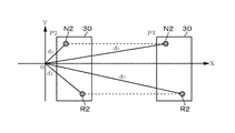
ノズルアーム30における第1の洗浄液ノズル41、第2の洗浄液ノズル43、第1の窒素ガスノズル51及び第2の窒素ガスノズル53の配置について説明する。なお以下の説明中において、便宜上第1の洗浄液ノズル41及び第2の洗浄液ノズル43から吐出される洗浄液を夫々第1の洗浄液及び第2の洗浄液とし、第1の窒素ガスノズル51及び第2の窒素ガスノズル53から吐出される窒素ガスを夫々第1の窒素ガス及び第2の窒素ガスとして記載する。また後述の「吐出位置」とは、洗浄液ノズル(41、43)、または、ガスノズル(51、53)から吐出された洗浄液、またはガスがウエハWの表面に吐出された時のウエハW上の吐出領域の概ね中心部を指している。また吐出位置をX、Y座標で表す場合には、ウエハWの中心部を原点とし、X方向に伸びる軸をX軸、Y方向に伸びる軸をY軸とし、後述の図6〜図10中では、右側及び上側を「正の領域」としている。
The arrangement of the first
第1の洗浄液ノズル41は、その吐出位置R1がX=30mm、Y=0mmになる位置に配置した時に、第1の窒素ガスノズル51の吐出位置N1が、X=15mm、Y=0mmとなるように設けられる。第2の洗浄液ノズル43は、第1の洗浄液ノズル41の吐出位置R1がX=30mm、Y=0mmに位置しているときに、その吐出位置R2がウエハWの中心部を中心に、第1の洗浄液ノズル41の吐出位置R1を時計回りに回転させた位置、例えば、X=26mm、Y=−15mmの位置になるように設けられる。第2の窒素ガスノズル53は、第1の窒素ガスノズル51の吐出位置N1がX=15mm、Y=0mmに位置しているとき、その吐出位置N2が、第1の窒素ガスノズル51の吐出位置N1をウエハWの中心部を中心として、反時計回りに回転させた位置であって、そのX軸との距離が第2の洗浄液ノズル43の吐出位置R2のX軸からの距離よりも短い位置に設定される、この例では、第2の窒素ガスノズル53の吐出位置N2は、例えば、X=13mm、Y=7.5mmの位置に吐出するように設定する。また第2の窒素ガスノズル53は、ウエハWの周縁の方向に向かって吐出するように設けられており、第1の洗浄液ノズル41、第2の洗浄液ノズル43及び第1の窒素ガスノズル51、は、真下に向けて吐出するように設けられている。また第1の窒素ガスノズル51の吐出する先端部の高さは、ウエハWの表面の上方25mmの高さに設定されており、第2の窒素ガスノズル53の吐出する先端部の高さはウエハWの表面の上方5mmの高さに設定されている。
When the first
また基板洗浄装置は、図5に示すように制御部5を備えている。図5中の21はバスであり、バス21にはCPU22、メモリ23、及び基板洗浄装置が行う後述の動作における各ステップを実行するためのプログラム24が接続されている。図5中25はノズル移動部に備えられた駆動部、26は、ノズル移動部に備えられた昇降部である。この制御部5は、ノズルアーム30を移動させるための駆動部、昇降部、洗浄液供給部46、48、窒素ガス供給部56、58及びスピンチャック11を駆動するための回転機構13及びカップ体10の昇降機構18などを制御するための制御信号を、前記プログラム24に基づいて出力する。またこのプログラムは、例えばコンパクトディスク、ハードディスク、光磁気ディスク等の記憶媒体に収納され制御部5にインストールされる。
The substrate cleaning apparatus includes a
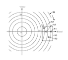
続いて第1の実施の形態の作用について説明する。例えば、露光処理を行ったウエハWが、図示しない外部の搬送機構により、スピンチャック11にウエハWの中心部と回転中心とが一致するように受け渡される。次いで外カップ16が上昇された後、ウエハWを例えば1000rpmの回転速度で回転させ、現像液ノズル62がウエハWの周縁の上方に位置する。その後ウエハWを回転させたまま、現像液ノズル62から現像液を吐出しながらウエハWの外側から中心部に向かって移動させ、その後所定時間当該中心部に現像液を供給し続ける。現像液が供給されると、ウエハWの表面のレジスト膜の例えば溶解性部位が溶解し、不溶解性の領域が残る。その後現像液ノズル62と入れ替わるようにノズルアーム30が移動し、現像液及び溶解物の除去を行うための洗浄工程が行われる。この洗浄工程について図6〜図13を参照しながら詳述すると、この洗浄工程は、以下のステップにより行われる。図6〜図10は、ノズルアーム30、及び夫々のノズル41,43,51,53から吐出される洗浄液や窒素ガスの吐出位置を模式化して表しており、吐出が行われている洗浄液及び窒素ガスの吐出位置には、ハッチングを付した。
Next, the operation of the first embodiment will be described. For example, the wafer W subjected to the exposure process is delivered to the
(ステップ1)
まず図6に示すように、ノズルアーム30がP0で示す位置まで移動し、第1の洗浄液ノズル41の吐出位置R1がウエハWの中心部に位置する。その後、図11に示すように、ウエハWを例えば1000rpmの回転速度で回転させながら、第1の洗浄液ノズル41から洗浄液、例えば純水を、30ml/秒の流量で例えば10秒間供給する。これによりウエハWに供給された第1の洗浄液はウエハWの回転による遠心力によりウエハWの中心部から周縁部に向かって広がり、現像液が洗浄液により洗い流される。
(Step 1)
First, as shown in FIG. 6, the
(ステップ2)
次いでウエハWの回転を維持しながら、第1の洗浄液ノズル41から第1の洗浄液を吐出した状態で、図7に示すようにノズルアーム30をX方向に沿って右側にP1まで移動させ、第1の窒素ガスノズル51の吐出位置N1をウエハWの中心部に位置させる。この時、第1の洗浄液ノズル41の吐出位置R1は、ウエハWの中心部からX方向右側に15mm離れて位置することになる。そして図12に示すように第1の窒素ガスノズル51から、ウエハWの中心部に向けて窒素ガスを吹き付ける。
(Step 2)
Next, while maintaining the rotation of the wafer W, with the first cleaning liquid discharged from the first
ウエハWの中心部は、遠心力が小さいため、前記第1の洗浄液ノズル41の吐出位置R1がウエハWの中心部から周縁側に移動しても、洗浄液の表面張力により液膜が張った状態が維持される。そこで液膜に向けて窒素ガスを吹き付けることにより、液膜が破れて、ウエハWの表面が露出した乾燥領域が形成される。この乾燥領域が形成されると、液膜は、ウエハWの回転による遠心力と液膜の表面張力とによりウエハWの周縁側に引っ張られる。そのため乾燥領域は、第1の洗浄液ノズル41の吐出位置R1に対応する位置(ウエハWの中心部を中心とし、第1の洗浄液ノズル41の吐出位置R1を通る同心円)まで瞬時に広がることになる。
Since the central portion of the wafer W has a small centrifugal force, the liquid film is stretched by the surface tension of the cleaning liquid even when the discharge position R1 of the first
(ステップ3)
続いてウエハWの回転を維持し、第1の洗浄液ノズル41及び第1の窒素ガスノズル51から夫々洗浄液及びガスを吐出したまま、図8に示すようにノズルアーム30をウエハWのX方向右側に15mm移動させ、P2に位置させる。即ち第1の洗浄液ノズル41の吐出位置R1がウエハWの中心部からX方向右側に30mm離れた位置に移動すると共に、第1の窒素ガスノズル51の吐出位置N1がウエハWの中心部からX方向右側に15mm離れた位置に移動し、これにより乾燥領域も第1の洗浄液ノズル41の吐出位置R1に対応する位置まで広がる。そのためステップ3では、図13に示すようにノズルアーム30の移動に伴い、第1の洗浄液ノズル41の吐出位置R1とウエハWの中心部との距離の増加するにつれて、液界面は徐々にウエハWの周縁方向に移動していく。
(Step 3)
Subsequently, the rotation of the wafer W is maintained, and while the cleaning liquid and the gas are discharged from the first
この時図14に示すように、第1の洗浄液ノズル41の吐出位置R1に対応する位置には、強い液流が発生しており、液界面に近い位置に窒素ガスを吐出することにより、液流の内縁が巻き上げられ、この液の巻き上げにより、液滴、生成物をウエハWの周縁側へ押しやるため、強い洗浄力を発揮する。
At this time, as shown in FIG. 14, a strong liquid flow is generated at a position corresponding to the discharge position R1 of the first
(ステップ4)
ノズルアーム30が位置P2まで移動した後、図9に示すように第1の洗浄液の吐出を停止して、第2の洗浄液の吐出を開始すると共に、第1の窒素ガスの吐出を停止して、第2の窒素ガスの吐出を開始する。第2の洗浄液ノズル43の吐出位置R2は、第1の洗浄液ノズル41の吐出位置R1がウエハWの中心部から30mm離れて位置しているとき、第2の洗浄液ノズル43の吐出位置R2とウエハWの中心部との距離が30mmになるように、即ちウエハWの中心部を中心とする同一の円の上に第1の洗浄液ノズル41の吐出位置R1、第2の洗浄液ノズル43の吐出位置R2が位置するように設定されている。従って洗浄液を吐出するノズルを第1の洗浄液ノズル41から第2の洗浄液ノズル43に切り替えた場合にも、ウエハWの表面に形成される液界面の位置は変化しないことになる。また既述のように第1の洗浄液ノズル41の吐出位置R1がウエハWの中心部から30mm離れて位置するとき、第1の窒素ガスノズル51の吐出位置N1が、ウエハWの中心部から右側に15mm離れるように設定されている。そして、第2の窒素ガスノズル53は、その時の第2の窒素ガスノズル53の吐出位置N2がウエハWの中心部から15mm離れて位置するように設けられている。従って窒素ガスを吐出するノズルを第1の窒素ガスノズル51から第2の窒素ガスノズル53に切り替えた場合にも、窒素ガスの吐出位置から液界面までの距離も変化しないことになる。
(Step 4)
After the
また第2の窒素ガスノズル53は、第1の窒素ガスノズル51の吐出流量と比べて多くの流量の窒素ガスを吐出すると共に、図4に示すように吐出口がウエハWの周縁側に向いている。従って、第2の窒素ガスノズル53に切り替えることにより窒素ガスの吹付による液界面を押す力が強くなる。この時、窒素ガスの吐出位置と洗浄液の吐出位置とが近い場合には、ガスの吐出の衝撃により洗浄液の液撥ねが起こる虞がある。第2の洗浄液ノズル43の吐出位置R2と第2の窒素ガスノズル53の吐出位置N2との距離は、第1の洗浄液ノズル41の吐出位置R1と第1の窒素ガスノズル51の吐出位置N1との距離よりも長くなるように設定されている。従って第2の窒素ガスノズル53に切り替え、窒素ガスの流量を大きくした場合にも、液撥ねを抑制することができる。
Further, the second
(ステップ5)
続いてノズルアーム30をウエハWの周縁側に向けて、X方向に15mm/秒の速度で移動させる。図10はノズルアーム30がP2よりもウエハWの周縁に近いP3に位置している状態を示している。第2の洗浄液ノズル43の吐出位置R2からウエハWの中心部までの距離d2と、第2の窒素ガスノズル53の吐出位置N2からウエハWの中心部までの距離d3との差(d2−d3)は、図15に示すようにノズルアーム30がP2に位置しているときよりも、P3に位置しているときの方が短くなる。
(Step 5)
Subsequently, the
ここでノズルアーム30の移動に伴う前記d2、d3の各変化について説明する。ノズルの吐出位置を既述のX‐Y座標平面(x≧0とする)で表す。ノズルアーム30がP2からx方向に沿って右側に距離k移動した場合の第2の洗浄液ノズル43の吐出位置R2及び第2の窒素ガスノズル53の吐出位置N2の各ノズルの座標は、図16(a)に示すように、
ノズルアーム30がP2に位置する時のN2=(Na、Nb)
ノズルアーム30がP2に位置する時のR2=(Ra、Rb)
ノズルアーム30が距離k移動した後のN2=(Na+k、Nb)
ノズルアーム30が距離k移動した後のR2=(Ra+k、Rb)
となる。従って移動距離をxと置いた場合のd2及びd3は、
ノズルアーム30がP3に位置する時のd2=√[(Ra+x)2+Rb2]
ノズルアーム30がP3に位置する時のd3=√[(Na+x)2+Nb2]
となる。
Here, each change of said d2 and d3 accompanying the movement of the
N2 when the
R2 = (Ra, Rb) when the
N2 after the
R2 = (Ra + k, Rb) after the
It becomes. Therefore, d2 and d3 when the movement distance is set to x are
D2 = √ [(Ra + x) 2 + Rb 2 ] when the
D3 = √ [(Na + x) 2 + Nb 2 ] when the
It becomes.
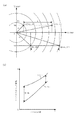
ノズルアーム30をX方向に沿って右側に移動させた時の第2の洗浄液ノズル43の吐出位置R2のウエハWの中心部からの距離d2は、図16(b)中の(1)のようなグラフを描く。またノズルアーム30をX方向に沿って右側に移動させた時の第2の窒素ガスノズル53の吐出位置N2のウエハWの中心部からの距離d3を考えると、第2の窒素ガスノズル53の吐出位置N2は、第2の洗浄液ノズル43の吐出位置R2よりもX軸に近い位置にあり、よりウエハWの中心部に近い位置にある。従ってd3は、d2よりも移動前(x=0)のウエハWの中心部までの距離は小さくなり、X方向右側にd2と同じ距離を移動した時に、増加率が大きくなる。そのためノズルアーム30の移動距離xとノズルの吐出位置のウエハWの中心部からの距離d2を示すグラフは、図16B中の(2)のようなグラフを描く。従って第2の洗浄液ノズル43から洗浄液を吐出し、第2の窒素ガスノズル53から窒素ガスを吐出したまま、ノズルアーム30をX方向に沿って右側にウエハWの周縁に向けて移動させた場合に、洗浄液の吐出位置のウエハWの中心部からの距離d3と、窒素ガスの吐出位置のウエハWの中心部からの距離d3との差(d2−d3)は、ノズルアーム30の移動に従い徐々に短くなる。
The distance d2 from the center of the wafer W at the discharge position R2 of the second
前述のようにウエハWを回転させながら洗浄液を供給しているため、洗浄液の液界面の位置は、洗浄液の吐出位置の僅かに内側となる円周に沿った位置となる。そのため、前記第2の洗浄液ノズル43の吐出位置R2からウエハの中心部までの距離d2と第2の窒素ガスノズル53の吐出位置N2からウエハの中心部までの距離d3との差が、窒素ガスの吐出位置から液界面までの距離となる。図17は、ウエハWの中心部から液界面までの距離と液界面と窒素ガスの吐出位置との離間距離(d2−d3)の変化を示す特性図である。図17に示すようにノズルアーム30がP2の位置(液界面がウエハWの中心部から30mmの位置)に移動するまでは、第1の洗浄液ノズル41及び第1の窒素ガスノズル51を使用して洗浄を行っているため、液界面と窒素ガスの吐出位置の距離は変わらず一定である。次いでノズルアーム30がP2(液界面がウエハWの中心部から30mmの位置)に達した後は、洗浄液及びガスの吐出が第2の洗浄液ノズル43及び第2の窒素ガスノズル53に切り替わる。このためその後に、ノズルアーム30がX軸に沿ってウエハWの周縁側に移動するに従って、液界面と窒素ガスの吐出位置とは互いに徐々近づいていくことになる。
Since the cleaning liquid is supplied while rotating the wafer W as described above, the position of the liquid interface of the cleaning liquid is a position along the circumference slightly inside the discharge position of the cleaning liquid. Therefore, the difference between the distance d2 from the discharge position R2 of the second
ウエハの周縁よりの領域において窒素ガスの供給位置を液界面に近づけた場合の作用について検討する。ウエハWの回転による遠心力により、洗浄液をウエハの周方向に押し流してウエハWの表面の洗浄を行う場合に、ウエハWの周縁寄りの部位ほど、洗浄液がウエハWの中心部側から寄せられるため、洗浄液の液膜が厚くなる。洗浄液の液膜が厚くなると、流れにくくなってしまうため液残りや液千切れが生じやすくなる。上述の実施の形態では、ウエハWの中心部から30mm以上離れた領域では、窒素ガスの吐出流量を大きくしている。そのため、窒素ガスにより液界面を周縁方向に押す力が強くなっている。またウエハWの中心部から30mm以上離れた領域では、ノズルアーム30がウエハWの周縁に近づくにつれて、窒素ガスの吐出位置が液界面に近づいている。そのため窒素ガスによる液界面を押す力がウエハWの周縁に近づくにつれて徐々に大きくなる。従ってウエハWの周縁寄りの領域では、液界面がウエハWの周縁に近づくにしたがって、洗浄液の量は徐々に増えるが、液界面をウエハの周縁方向に押す力も大きくなるため、液残りや液千切れを抑制することができる。
The action when the nitrogen gas supply position is brought close to the liquid interface in the region from the periphery of the wafer will be examined. When cleaning the surface of the wafer W by washing the cleaning liquid in the circumferential direction of the wafer by the centrifugal force generated by the rotation of the wafer W, the cleaning liquid is drawn closer to the periphery of the wafer W from the center side of the wafer W. The liquid film of the cleaning liquid becomes thick. When the liquid film of the cleaning liquid becomes thick, it becomes difficult to flow, so that liquid residue and liquid tearing are likely to occur. In the embodiment described above, the discharge flow rate of nitrogen gas is increased in a
上述の実施の形態では、第1の洗浄液ノズル41及び第1の窒素ガスノズル51を用いて、ウエハWを回転させながらウエハWの中心部に洗浄液及び窒素ガスを順次吐出し、両ノズル41、51をウエハWの周縁側に移動している。更にその後、第1の洗浄液ノズル41の移動軌跡から外れる位置に設定された第2の洗浄液ノズル43に洗浄液の吐出を切り替え、また第2の窒素ガスノズル53に窒素ガスの吐出を切り替える。そして洗浄液の吐出及びガスの吐出を行いながら両ノズル43、53をウエハWの周縁側に向けて移動させることにより、窒素ガスの吐出位置を徐々に液界面に近づけている。従ってウエハWの周縁に近い領域ほど、窒素ガスにより液界面を押す力が強くなって洗浄効果が高くなり、洗浄液の液残りや液千切れを抑制することができ、良好な洗浄を行うことができる。
そしてノズルアーム30の移動途中で第2の洗浄液ノズル43及び第2の窒素ガスノズル53を用いるようにしている。第2の窒素ガスノズル53は窒素ガスの吐出流量の多いため液界面を押す力が強くなり、洗浄液の吐出位置と窒素ガスの吐出位置との距離も話すことができるため、液撥ねを抑えることができる。
In the above-described embodiment, the first
The second
また上述の実施の形態では、共通のノズルアーム30に第1の洗浄液ノズル41、第2の洗浄液ノズル43、第1の窒素ガスノズル51及び第2の窒素ガスノズル53を設けている。そのため、各ノズルの駆動系を共通にすることができるので基板洗浄装置のコストを低くすることができ、またノズルアーム30や駆動系の設置スペースが狭くて済む。またウエハWの表面における窒素ガスの吐出位置と、洗浄液の液界面との距離は、後述するように、9mm〜17mmの範囲であることが望ましく、事前にシミュレーションを行うことにより、窒素ガスの吐出位置と、洗浄液の液界面との距離がこの範囲で変化するように、夫々のノズルの位置を設定することが望ましい。
In the above-described embodiment, the first
さらにノズルアーム30がP1の位置にあるときに、第2の洗浄液ノズル43の吐出位置R2と、第1の洗浄液ノズル41の吐出位置R1とが、ウエハの中心部を中心とした同じ同心円上に位置するように設定されていなくてもよい。またノズルアーム30がP1に位置しているときに、第2の洗浄液ノズル43の吐出位置R2は、その時の第1洗浄液ノズル41の吐出位置R1よりウエハWの中心部に近い位置であってもよい。
Further, when the
また本発明は、第2の窒素ガスノズル53を設けることに限定されるものではなく、ステップ4以降の工程において、第1の窒素ガスノズル51を使用してウエハWの洗浄を行うようにしてもよい。その場合においても洗浄液の液界面がウエハWの周縁に近づくに従い、窒素ガスの吐出位置を液界面に近づけることができる。従って液界面がウエハWの周縁に近づくに従い、液界面を押す力を強くすることができるため、同様の効果が得られる。
Further, the present invention is not limited to the provision of the second
また第1の洗浄液ノズル41、第2の洗浄液ノズル43、第1の窒素ガスノズル51、第2の窒素ガスノズル53は、夫々別々に独立して移動可能なノズル移動部に設けられていてもよい。さらに第2の窒素ガスノズル53を設けずに第1の窒素ガスノズル51のみを用いて、ステップ4以降の工程においてもウエハWの洗浄を行うようにしてもよい。さらに本発明は、基板の水の接触角の大きい場合に効果が大きく、例えば水の接触角が65°以上であるレジスト膜の表面を洗浄する場合により効果が大きい。
Further, the first
さらに第1の実施の形態においては、ステップ4において、第1の窒素ガスノズル51の吐出を停止し、第2の窒素ガスノズル53から窒素ガスを吐出しているが、ステップ4及びステップ5において、第2の洗浄液ノズル43及び第2の窒素ガスノズル53から夫々洗浄液及びガスを吐出しているときに第1の窒素ガスノズル51から例えば少流量のガスを吐出している場合であっても本発明の技術的範囲に含まれる。
Further, in the first embodiment, in
[第1の実施の形態の変形例]
また第1の実施の形態の変形例として、ノズルアーム30は、旋回アームに設けられていてもよい。即ち第1の実施の形態では、ノズルアーム30をX方向に沿って移動させることにより、各ノズルを直線に沿って移動させているが、各ノズルを円弧軌跡を描くように移動させてもよい。図18はこのような例を示し、ノズルアーム30として図18中、O1を回転中心として旋回する構成のものを用いている。駆動部は、アームを旋回させる図示しない回転部となり、また図示しない昇降部が設けられ、ノズルアーム30は昇降自在に構成される。従ってノズルアーム30、駆動部及び昇降部がノズル移動部になる。第1の洗浄液ノズル41の吐出位置R1と第1の窒素ガスノズル51の吐出位置N1は、ウエハWの中心部を通る円弧軌跡上に設けられる。この実施の形態の場合には、ステップ2でノズルアーム30を旋回させることにより、第1の洗浄液ノズル41の吐出位置R1がウエハWの中心部から15mmから離れるように移動され、その時第1の窒素ガスノズル51の吐出位置N1がウエハWの中心部に位置することになる。
[Modification of First Embodiment]
As a modification of the first embodiment, the
またステップ3においては、第1の洗浄液ノズル41の吐出位置R1がウエハWの中心部から30mm離れるように移動される。この時第1の窒素ガスノズル51の吐出位置N1は、液界面に近づくが、近づく距離は、極わずかであるため、第1の窒素ガスノズル51の吐出位置N1と液界面との距離はほとんど変化せず一定として取り扱うことができる。さらにステップ4において洗浄液及び窒素ガスを夫々第2の洗浄液ノズル43及び第2の窒素ガスノズル53から吐出するように切り替えた後、ステップ5では、ノズルアーム30を旋回させて、夫々のノズルをウエハWの周縁側に移動させる。
In
ノズルアーム30を旋回させることによる第2の洗浄液ノズル43の吐出位置R2のウエハWの中心部からの距離と、第2の窒素ガスノズル53の吐出位置N2とウエハWの中心部からの距離の差の関係について説明する。図18中のVは、ノズルアーム30の回転軸O1とウエハの中心部との距離、u及びθは所定の吐出位置を示すパラメータであり、図18中では、ノズルアーム30がP4の位置にあるときの第2の窒素ガスノズル53の吐出位置N2のパラメータを示す。uは、回転軸O1を中心として、ウエハWの中心部を通る円弧軌跡からの外れる距離(円弧軌跡の外側への外れを+、中心側への外れを−とする)、θはノズルアーム30の回転角度である(ノズルが回転軸O1とウエハWの中心部を結ぶ直線上に位置する場合を0とし、時計回りの回転方向を+としている)。
The difference between the distance from the center of the wafer W at the discharge position R2 of the second
回転軸O1がウエハの領域より外にあり、ノズルをウエハWの中心部から周縁へ移動させるとθは、0度〜90度の範囲でウエハWの周縁に到達する。ノズルアーム30を旋回させた時のノズルアーム30に設けられたノズルの吐出位置からウエハ中心部までの距離dの変化を考えると、d=√[u2+2uV+2V2−2V(u+V)cosθ]となる。従ってノズルアーム30を旋回させた時のノズルの吐出位置とウエハの中心部との距離は、ノズルアーム30の回転軸O1とウエハWの中心部との距離V、回転角度θ、円弧軌跡からの外れる距離u、により決定される。
When the rotation axis O1 is outside the region of the wafer and the nozzle is moved from the center of the wafer W to the periphery, θ reaches the periphery of the wafer W in the range of 0 to 90 degrees. Considering the change in the distance d from the discharge position of the nozzle provided on the
従って図18に示すようなアームを旋回させた時の第2の洗浄液の吐出位置R2のウエハWの中心部からの距離の変化d2は、図19中の(3)で示す実線で表される。またアームを旋回させた時の第2の窒素ガスノズル53の吐出位置N2のウエハWの中心部からの距離の変化d3は、図19中の(4)で示す実線で表される。そのため、アームを旋回させてノズルアーム30をウエハWの周縁方向に旋回させるにしたがって、第2の洗浄液ノズル43の吐出位置R2のウエハWの中心部との距離d2と、第2の窒素ガスノズル53の吐出位置N2とウエハWの中心部との距離d3との差(d2−d3)は徐々に短くなることになる。そのため、ノズルアーム30がウエハの周縁に向かって移動するにしたがって、液界面と窒素ガスの吐出位置との距離は徐々に近づき、液界面を押す力が強くなる。従って液残りや液千切れを抑制することができる。
Accordingly, a change d2 in the distance from the center of the wafer W at the second cleaning liquid discharge position R2 when the arm as shown in FIG. 18 is swung is represented by a solid line indicated by (3) in FIG. . A change d3 in the distance from the center of the wafer W at the discharge position N2 of the second
[第2の実施の形態]
また第2の実施の形態に係る基板洗浄装置として、2本のノズルアームを備えるように構成してもよい。第2の実施の形態は、例えば図20、図21に示すように第2の洗浄液ノズル53を備えていないことを除いて、第1の実施の形態に示したノズルアーム30と同様に構成された第1のノズルアーム38と、他の窒素ガスノズル59を備えた第2のノズルアーム39とを備えている。図中60は、現像用のノズルアーム、61は現像液用のノズルバス、63はガイドレールである。第2のノズルアーム39は、ノズルアーム30と同様に構成された駆動部、昇降部により支持され、第1のノズルアーム38のガイドレール33と平行に伸びるガイドレール70に沿って移動するように構成されている。第2のノズルアーム39は、ウエハW上の第1のノズルアーム38の移動する領域とは異なる領域、例えばウエハWの中心部からX方向に沿って左側の領域を移動するように構成されている。また他の窒素ガスノズル59は、第1の窒素ガスノズル51及び第2の窒素ガスノズル53と同様に配管70を介して他の窒素ガス供給部71と接続されている。
[Second Embodiment]
Further, the substrate cleaning apparatus according to the second embodiment may be configured to include two nozzle arms. The second embodiment is configured in the same manner as the
第2の実施の形態にかかる基板洗浄装置によるウエハWの洗浄処理を図22〜図26を用いて説明する。ステップ1及びステップ3は、図22、23に示すように第1の実施の形態に示したステップ1〜ステップ3と同様な工程であり、R1、N1が順次ウエハWの中心部に位置するように第1のノズルアーム38が移動する。第2のノズルアーム39は、他の窒素ガスノズル59から吐出される窒素ガスの吐出位置N3が例えばウエハWの中心部から、X方向に沿って図中の左方向に60mmの位置となる地点で待機しておく。
The cleaning process of the wafer W by the substrate cleaning apparatus according to the second embodiment will be described with reference to FIGS.
(ステップ4)
図24に示すように第1の洗浄液ノズル41の吐出位置R1がウエハWの中心部から30mmに位置し、第1の窒素ガスノズル51の吐出位置N1がウエハWの中心部から15mmに位置した後、窒素ガスを吐出するノズルを第1の窒素ガスノズル51から第2の窒素ガスノズル53に切り替える。
(Step 4)
24, after the discharge position R1 of the first
(ステップ5)
その後第2の窒素ガスノズル53の吐出位置N2のウエハWの中心部からの距離(この例では、60mm)と、他の窒素ガスノズル59の吐出位置N3とウエハWの中心部からの距離が等しくなる位置まで移動する。この間第2の洗浄液の吐出と、第2の窒素ガスとの吐出とが行われており、第2の窒素ガスノズル53は、第1の窒素ガスノズル51よりも流量が大きいため、ステップ5では、ステップ1〜3に比べて液界面を強い力で押すことができる。
(Step 5)
Thereafter, the distance from the center of the wafer W at the discharge position N2 of the second nitrogen gas nozzle 53 (in this example, 60 mm) is equal to the distance from the discharge position N3 of the other
(ステップ6)
その後、窒素ガスを吐出するノズルを他の窒素ガスノズル59に切り替え、第1のノズルアーム38及び第2のノズルアーム39をウエハWの周縁方向に移動させる。図25は、窒素ガスの吐出を第2の窒素ガスノズル53から他の窒素ガスノズル59に切り替えた後の状態を示している。この時第1のノズルアーム38は、図26に示すようにX方向に沿って、右側に移動するが、第2のノズルアーム39は、X方向に沿って左側に移動する。また第2のノズルアーム39の移動速度は、第1のノズルアーム38より速い速度に設定される。このため洗浄液の吐出位置からウエハWの中心部までの距離L1と窒素ガスの吐出位置からウエハWの中心部までの距離L2との差が徐々に小さくなる。一例をあげるとL2−L1が17mmから9mmまで近づく。この結果、他の窒素ガスノズル59の吐出位置N3は、ウエハWの周縁側に近づくにつれて液界面に近づくため、窒素ガスが液界面を押す力が徐々に増すことになる。そのため液残りや液千切れが抑制され、第1の実施の形態と同様の効果を得ることができる。
また第2のノズルアーム39の他の窒素ガスノズル59からガスを吐出しながら当該第2のノズルアーム39をウエハWの周縁側に移動させているときに、第1のノズルアーム38の窒素ガスノズル51、53からガスを、例えば少流量で吐出する場合も技術的範囲に含まれる。
(Step 6)
Thereafter, the nozzle for discharging the nitrogen gas is switched to another
Further, when the
ここで第1の実施の形態あるいは第2の実施の形態において、ウエハWの中心部に洗浄液を供給した後に第1の窒素ガスノズル51から当該中心部に窒素ガスを吹き付けるときの好ましい例について述べる。背景技術の欄にて述べたように、レジストと下地との接触角の差が大きい場合に下地の脇に液が残りやすく、液残りが発生すると残渣欠陥(残渣が存在することによる現像欠陥)の要因となる。例えば下地にシリコン反射膜を使用する場合には、前記接触角の差がかなり大きくなることから、このような場合でもより一層液残りを抑えることができるように洗浄処理を行うことが好ましい。ウエハWの中心部近辺に着目すると、この部分は遠心力が弱いため液残りが発生しやすい。そこでウエハWの中央部において第1の窒素ガスの吐出時間を長くすることも有効な手法ではあるが、処理時間が長くなり、スループットの低下の要因になるおそれがある。
Here, in the first embodiment or the second embodiment, a preferable example in which nitrogen gas is blown from the first
このような観点からすると、有効な手法の一例として、第1の窒素ガスノズル51の吐出する先端部の高さをウエハWの表面の上方、例えば5mmの高さに設定する例が挙げられる。この場合には、第1の窒素ガスノズル51の先端部からウエハWの表面までの距離が短くなり、第1の窒素ガスノズル51から吐出された窒素ガスがウエハWの表面に到達するまでのガスの拡散を抑えることができ、より強いせん断応力で液界面を押すことができる。
そして窒素ガスのせん断応力を高めた上で、窒素ガスを前半は低流量で供給して乾燥コア(液の中央部の乾燥領域)を形成した後に、後半は高流量で供給して乾燥コアを広げるようにする。このような手法によれば、ウエハWの中心部の液残りがより一層抑えられる。低流量の時間と高流量の時間とは同じであることに限られない。具体例については後述の実施例の欄に記載している。
From this point of view, an example of an effective method is an example in which the height of the tip portion discharged from the first
After increasing the shear stress of the nitrogen gas, the nitrogen gas is supplied at a low flow rate in the first half to form a dry core (drying area in the center of the liquid), and then the nitrogen gas is supplied at a high flow rate in the latter half. Try to spread. According to such a method, the liquid residue at the center of the wafer W can be further suppressed. The time of the low flow rate and the time of the high flow rate are not limited to being the same. Specific examples are described in the “Example” section below.
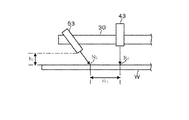
またウエハWの中心部以外の領域に置ける液残りをおさえるための有効な手法について記載する。この手法の一つとして、第1の実施の形態における第2の窒素ガスノズル53を例にとると、図27に示すように第2の窒素ガスノズル53を、窒素ガスの吐出方向の水平面に対する角度θ2が例えば45度の角度となるように設ける。窒素ガスの吐出方向とは、吐出口から吐出されるガス流の中心が向いている方向である。
第2の窒素ガスノズル53から窒素ガスをウエハWの表面に対して斜めに吐出すると、ウエハWの表面に形成される液界面にかかるせん断応力は、窒素ガスをウエハWに対して垂直に吐出した場合においてウエハW表面に形成される液界面にかかるせん断応力よりも大きくなる。第2の窒素ガスノズル53の窒素ガスの吐出方向の水平面に対する角度θ2が45度の場合の液面にかかるせん断応力は、角度θ2が90度の場合に液面にかかるせん断応力よりも1.5倍の強さとなる。このように第2の窒素ガスノズル53の窒素ガスの吐出方向を水平面に対して45度に設定して液面にかかるせん断応力を大きくすれば、ノズルアーム30のスキャン速度を速くした場合にも液残りや液千切れを抑制することができる。
第2の窒素ガスノズル53の窒素ガスの吐出方向を水平面に対して90度に設定した場合においても、窒素ガスの流量を大きくすることで液面に対して大きなせん断応力が得られるが、液撥ねやミスト発生のおそれがある。従って第2の窒素ガスノズル53の窒素ガスの吐出方向を斜めに設定することが有効であり、特に水平面に対して90度に設定することが有利である。
Also, an effective technique for suppressing the liquid residue that can be placed in a region other than the central portion of the wafer W will be described. As an example of this method, taking the second
When nitrogen gas is discharged from the second
Even when the discharge direction of the nitrogen gas from the second
また第2の窒素ガスノズル53の吐出位置N2と液の内縁(液界面)との間の距離について残渣低減のための適切な距離は、ウエハW上のレジストの種類、下地膜の材質、洗浄処理のレシピなどに応じて異なってくる。このため、洗浄処理の処理種別の中のパラメータとして前記距離を加え、処理種別が選択されることにより前記距離が決定されるようにすることが好ましい。第2の窒素ガスノズル53の吐出位置N2と液の内縁との間の距離は、窒素ガスの吐出方向を水平面から斜めにした場合、例えば窒素ガスの吐出方向を水平面に対して45度に設定した場合には、第2の窒素ガスノズル53の高さを調整することにより変更することができる。
Further, regarding the distance between the discharge position N2 of the second
例えば図28に示すように第2の窒素ガスノズル53の先端部のウエハWの表面からの高さがh1のときウエハW表面における第2の窒素ガスノズル53の吐出位置N2から第2の洗浄液ノズル43の吐出位置R2までの距離が例えばd11となる。
そして図29に示すように第2の窒素ガスノズル53の先端部のウエハWの表面からの高さがh2となるようにノズルアーム30を上昇させると、第2の窒素ガスノズル53の吐出位置N2は、ウエハWの表面を第2の窒素ガスノズル53の先端部が傾く方向に移動する。一方で第2の洗浄液ノズル43は、真下に吐出するように設けているため、ノズルアーム30を昇降させてもウエハW表面における第2の洗浄液ノズル43の吐出位置R2は変わらない。従って第2の窒素ガスノズル53の吐出位置N2は、第2の洗浄液ノズル43の吐出位置R2に近づき、第2の窒素ガスノズル53の吐出位置N2から第2の洗浄液ノズル43の吐出位置R2までの距離はd12となる。このようにノズルアーム30を昇降させることにより、第2の窒素ガスノズル53の吐出位置N2から第2の洗浄液ノズル43の吐出位置R2までの距離を変更することができる。なお、第2の洗浄液ノズル43の洗浄液の吐出方向は、真下に向いていなくてもよく、例えば第2の窒素ガスノズル53のガスの吐出方向と異なる角度(水平面に対する角度)であれば、斜めであってもよい。
For example, as shown in FIG. 28, when the height of the tip of the second
Then, as shown in FIG. 29, when the
そこで図27に示すように予めウエハWの洗浄処理の種別に対応して、事前に第2の窒素ガスノズル53の吐出位置N2から液面の内縁までの適切な距離を求め、制御部5におけるメモリ23に、ウエハWの洗浄処理の種別(レシピ)と、ノズルアーム30の高さの設定値と、を対応づけたデータを記憶しておく。そして制御部5によりメモリからウエハWの洗浄処理の種別に対応したノズルアーム30の高さを読み出し、昇降部26にノズルアーム30を昇降させる制御信号を出力する。従ってウエハWのロットに応じて洗浄処理の種別が選択されたとき、ノズルアーム30の高さも決まってくる。洗浄処理の種別は、パラメータがノズルアーム30の高さだけの場合であってもよく、この場合、ノズルアーム30の高さが複数設定されている場合、各高さが洗浄処理の種別となる。
Therefore, as shown in FIG. 27, an appropriate distance from the discharge position N2 of the second
このように構成することで、ウエハWの洗浄処理の種別に対応して、第2の窒素ガスの吐出位置N2から液面の内縁までを適切な距離に設定することができるため、ウエハWの中心部以外の領域においても洗浄液の液残りや液千切れを抑制することができ、良好な洗浄を行うことができる。 With this configuration, it is possible to set an appropriate distance from the discharge position N2 of the second nitrogen gas to the inner edge of the liquid level in accordance with the type of cleaning process for the wafer W. Even in a region other than the central portion, it is possible to suppress the remaining liquid of the cleaning liquid and the tearing of the liquid, and good cleaning can be performed.
窒素ガスの吐出方向と水平面との角度θ2は、例えば30度〜60度に設定することでせん断応力を強めることができるが、角度θ2を45度±5度に設定した時にせん断応力が強くなり、より一層大きな効果が得られる。 For example, the angle θ2 between the discharge direction of the nitrogen gas and the horizontal plane can be increased by setting the angle θ2 to 30 degrees to 60 degrees, for example, but the shear stress increases when the angle θ2 is set to 45 degrees ± 5 degrees. An even greater effect can be obtained.
[実施例1]
本発明を評価するために第1の実施の形態に係る基板洗浄装置を用い、評価パターンを用いて露光したウエハWに現像液を供給し、実施例及び比較例に係る洗浄処理を行いパターンの欠陥の計数を行った。実施例に用いたウエハWの表面に形成されたレジスト膜と反射防止膜との接触角差は、37.8°である。洗浄処理中のウエハの回転速度は750rpmに設定し、ノズルアーム30の移動速度は、10mm/秒に設定した。また比較例として、実施例と同様の構成の基板洗浄装置を用い、ステップ2の終了後、洗浄液ノズル及び窒素ガスノズルの切り替えを行わず、第1の洗浄液及び第1の窒素ガスをウエハに向けて吐出した状態でノズルアーム30をX方向に沿ってウエハWの周縁に向けて移動させて、ウエハの洗浄を行った。この場合ガスの吐出位置から液界面までの距離は、一定である。比較例では、2561個のパターンの欠陥が確認できたが、実施例では、パターンの欠陥は8個に軽減され、本発明の洗浄効果が高いことが確認できた。
[Example 1]
In order to evaluate the present invention, the substrate cleaning apparatus according to the first embodiment is used, a developing solution is supplied to the wafer W exposed using the evaluation pattern, and the cleaning process according to the example and the comparative example is performed. Defect counts were made. The contact angle difference between the resist film formed on the surface of the wafer W used in the example and the antireflection film is 37.8 °. The rotation speed of the wafer during the cleaning process was set to 750 rpm, and the moving speed of the
[評価試験]
窒素ガスの吐出位置と洗浄液の液界面との離間距離が、ウエハWの洗浄効果にもたらす影響を調べるために以下の評価試験を行った。基板洗浄装置は、ノズルアーム30に設置する第1の窒素ガスノズル51の位置を変えることにより、液界面と窒素ガスの吐出位置との距離を以下のように7通りに設定し、第1の洗浄液ノズル41及び第1の窒素ガスノズル51のみを用いて、評価パターンを用いて露光したウエハWに現像液を供給した後、洗浄を行った。ウエハWの洗浄後、乾燥処理を行いウエハの中心部から12〜15cmの領域に存在するパターンの欠陥の数を計数した。結果は以下の表1のとおりである。
[表1]

In order to investigate the influence of the separation distance between the discharge position of the nitrogen gas and the liquid interface of the cleaning liquid on the cleaning effect of the wafer W, the following evaluation test was performed. The substrate cleaning apparatus sets the distance between the liquid interface and the nitrogen gas discharge position in seven ways as follows by changing the position of the first
[Table 1]
パターンの欠陥の数を十分に抑えるには、窒素ガス吐出位置と液界面との距離は、9mm〜17mmの範囲に設定することが望ましいといえる。 In order to sufficiently suppress the number of pattern defects, it can be said that the distance between the nitrogen gas discharge position and the liquid interface is desirably set in the range of 9 mm to 17 mm.
[実施例2]
本発明を評価するために第1の実施の形態に係る基板洗浄装置を用い、評価パターンを用いて露光したウエハWに現像液を供給し、第1の窒素ガスノズル51の先端部の高さをウエハWの上方25mmと5mmとに設定して洗浄処理を行い、パターンを形成してウエハWの表面を検査した。ウエハWの中心部から3cm以内における残渣欠陥(現像欠陥)の計数を行った。第1の窒素ガスノズル51の先端部の高さをウエハWの上方25mmに設定した場合の欠陥は8個であり、第1の窒素ガスノズル51の先端部の高さをウエハWの上方5mmに設定した場合の欠陥は3個であった。第1の窒素ガスノズル51の先端部の高さを低く設定することでウエハWの中心部付近の液残りを減少することができると言える。
[Example 2]
In order to evaluate the present invention, the substrate cleaning apparatus according to the first embodiment is used, the developing solution is supplied to the wafer W exposed using the evaluation pattern, and the height of the tip of the first
[実施例3]
水平面に対して45度の角度で吐出される窒素ガスの吐出位置と洗浄液の液界面との距離が、ウエハWの洗浄効果にもたらす影響を調べるために以下の評価試験を行った。基板洗浄装置は、ノズルアーム30に設置する第2の窒素ガスノズル53を水平面から45度の角度に設け、その設置位置をウエハWの中心側に移動させた。第2の窒素ガスノズル53の吐出位置N2と洗浄液の液界面との距離をAmm、A+1mm、A+2mmの3通りに設定したところ、前記距離がA+1mmのときはAmmよりも欠陥がおよそ3倍になり、A+2mmはおよそ6倍になった。従って距離を変えることにより洗浄効果が変わることが理解される。
[Example 3]
In order to investigate the influence of the distance between the discharge position of the nitrogen gas discharged at an angle of 45 degrees with respect to the horizontal plane and the liquid interface of the cleaning liquid on the cleaning effect of the wafer W, the following evaluation test was performed. The substrate cleaning apparatus provided the second
1 カップモジュール
5 制御部
10 カップ体
11 スピンチャック
13 回転機構
30 ノズルアーム
33 ガイドレール
38 第1のノズルアーム
39 第2のノズルアーム
41 第1の洗浄液ノズル
43 第2の洗浄液ノズル
51 第1の窒素ガスノズル
53 第2の窒素ガスノズル
59 他の窒素ガスノズル
N1 第1の洗浄液ノズル41の吐出位置
N2 第2の洗浄液ノズル43の吐出位置
N3 他の窒素ガスノズル59の吐出位置
R1 第1の窒素ガスノズル51の吐出位置
R2 第2の窒素ガスノズル53の吐出位置
W ウエハ
DESCRIPTION OF
Claims (8)
基板を水平に保持する基板保持部と、
前記基板保持部を鉛直軸周りに回転させる回転機構と、
前記基板保持部に保持された基板に各々洗浄液を供給するための第1の洗浄液ノズル及び第2の洗浄液ノズルと、
前記基板保持部に保持された基板にガスを吐出する基板の中心部にガスを吐出するときに用いられる第1のガスノズルと、
前記第1のガスノズルの移動軌跡から外れる位置に設けられた第2のガスノズルと、
前記第1の洗浄液ノズル、第2の洗浄液ノズル、第1のガスノズル及び第2のガスノズルを移動させるためのノズル移動部と、
前記第1の洗浄液ノズルから洗浄液を基板の中心部に吐出するステップと、次いで前記洗浄液の吐出位置を前記基板の中心部から周縁側に移動させた後、前記第1のガスノズルからガスを当該中心部に吐出するステップと、続いて第1の洗浄液ノズル及び第1のガスノズルから夫々洗浄液及びガスの吐出を行いながら前記第1の洗浄液ノズル及び前記第1のガスノズルの各吐出位置を基板の周縁側に向けて移動させるステップと、次に前記第1の洗浄液ノズルから第2の洗浄液ノズルに洗浄液の吐出を切替えると共に、前記第1のガスノズルから第2のガスノズルにガスの吐出を切替え、第2の洗浄液ノズルからの洗浄液の吐出及び第2のガスノズルからのガスの吐出を行いながら当該第2の洗浄液ノズル及び当該第2のガスノズルの各吐出位置を基板の周縁側に向けて移動させるステップと、を実行するように制御信号を出力する制御部と、を備え、
前記第2の洗浄液ノズルは、吐出位置が第1の洗浄液ノズルの吐出位置の移動軌跡から外れる位置に設定され、
第2の洗浄液ノズル及び第2のガスノズルの各吐出位置から基板の中心部までの距離を、夫々d2及びd3とすると、第2の洗浄液ノズルから洗浄液を吐出しているときには、d3<d2であり、かつ第2の洗浄液ノズルが基板の周縁側に移動するにつれて、d2とd3との差が徐々に小さくなるように構成されていることを特徴とする基板洗浄装置。 In an apparatus for cleaning a substrate using a cleaning liquid and a gas while rotating the substrate,
A substrate holder for horizontally holding the substrate;
A rotation mechanism for rotating the substrate holder around a vertical axis;
A first cleaning liquid nozzle and a second cleaning liquid nozzle for supplying a cleaning liquid to each of the substrates held by the substrate holder;
A first gas nozzle that is used when gas is discharged to the center of the substrate that discharges gas to the substrate held by the substrate holder ;
A second gas nozzle provided at a position deviating from the movement locus of the first gas nozzle;
A nozzle moving unit for moving the first cleaning liquid nozzle, the second cleaning liquid nozzle , the first gas nozzle, and the second gas nozzle;
A step of discharging the cleaning liquid from the first cleaning liquid nozzle to the center of the substrate; and then, after the discharge position of the cleaning liquid is moved from the center of the substrate to the peripheral side, the gas is discharged from the first gas nozzle to the center. And discharging each of the first cleaning liquid nozzle and the first gas nozzle to the peripheral side of the substrate while discharging the cleaning liquid and the gas from the first cleaning liquid nozzle and the first gas nozzle, respectively. switching and moving in, then switches the discharge of the cleaning liquid to the second cleaning liquid nozzle from the first cleaning liquid nozzle Rutotomoni, the discharge of the gas to the second gas nozzle from the first nozzle toward the second each discharge from the cleaning liquid nozzle while the discharge of the gas from the discharge and a second gas nozzle of the cleaning solution the second cleaning liquid nozzle and said second nozzle And a control unit for outputting a control signal to perform the step of moving toward a location on the peripheral edge of the substrate, and
The second cleaning liquid nozzle is set at a position where the discharge position deviates from the movement locus of the discharge position of the first cleaning liquid nozzle,
If the distances from the respective discharge positions of the second cleaning liquid nozzle and the second gas nozzle to the center of the substrate are d2 and d3, respectively, d3 <d2 when the cleaning liquid is discharged from the second cleaning liquid nozzle. The substrate cleaning apparatus is configured so that the difference between d2 and d3 gradually decreases as the second cleaning liquid nozzle moves toward the peripheral edge of the substrate.
前記第2のガスノズルのガスの吐出方向は、水平面に対して30度〜60度の範囲で傾いており、
基板の洗浄処理の種別と基板に対する第2のガスノズルの吐出口の高さとを対応付けたデータを記憶する記憶部を備え、複数の洗浄処理の種別の中から選択された洗浄処理の種別に対応する第2のガスノズルの吐出口の高さを前記記憶部の中から読み出して前記昇降機構に制御信号を出力する制御部と、を備えたことを特徴とする請求項1または2に記載の基板洗浄装置。 The second cleaning liquid nozzle and the second gas nozzle are provided in a common nozzle moving unit that can be moved up and down by a lifting mechanism,
The gas discharge direction of the second gas nozzle is inclined in a range of 30 to 60 degrees with respect to a horizontal plane,
A storage unit that stores data that associates the type of substrate cleaning process with the height of the discharge port of the second gas nozzle with respect to the substrate, and corresponds to the type of cleaning process selected from a plurality of types of cleaning processes substrate according to claim 1 or 2 the discharge port of the height of the second gas nozzle, characterized in that and a control unit for outputting a control signal to said lifting mechanism reads out of the storage unit for Cleaning device.
基板を基板保持部に水平に保持する工程と、
前記基板保持部を鉛直軸周りに回転させながら、第1の洗浄液ノズルから洗浄液を基板の中心部に吐出する工程と、
次いで前記洗浄液の吐出位置を基板の周縁側に移動させた後、第1のガスノズルからガスを前記基板の中心部に吐出する工程と、
続いて第1の洗浄液ノズル及び第1のガスノズルから夫々洗浄液及びガスの吐出を行いながら前記第1の洗浄液ノズル及び前記第1のガスノズルの各吐出位置を基板の周縁側に向けて移動させる工程と、
次に前記第1の洗浄液ノズルから第2の洗浄液ノズルに洗浄液の吐出を切替えると共に、前記第1のガスノズルの移動軌跡から外れる位置において、前記第2の洗浄液ノズルと共通のノズル移動部に水平面に対して30度〜60度の範囲で傾いた状態で設けられた第2のガスノズルを用いて、前記第1のガスノズルから第2のガスノズルにガスの吐出を切替え、第2の洗浄液ノズルからの洗浄液の吐出及び第2のガスノズルからのガスの吐出を行いながら当該第2の洗浄液ノズル及び当該第2のガスノズルの各吐出位置を基板の周縁側に向けて移動させる工程と、
複数の洗浄処理の種別の中から選択された洗浄処理の種別に対応する第2のガスノズルの吐出口の高さを、基板の洗浄処理の種別と基板に対する第2のガスノズルの吐出口の高さとを対応付けたデータを記憶する記憶部の中から読み出して前記ノズル移動部を昇降させる昇降機構に出力して、第2のガスノズルの吐出口の高さを調整する工程と、を含み、
前記第2の洗浄液ノズルは、吐出位置が第1の洗浄液ノズルの吐出位置の移動軌跡から外れる位置に設定され、
前記第2の洗浄液ノズル及び第2のガスノズルの各吐出位置から基板の中心部までの距離を、夫々d2及びd3とすると、第2の洗浄液ノズルから洗浄液を吐出しているときには、d3<d2であり、かつ第2の洗浄液ノズルが基板の周縁側に移動するにつれて、d2とd3との差が徐々に小さくなることを特徴とする基板洗浄方法。 In a method of cleaning a substrate using a cleaning liquid and a gas while rotating the substrate,
Holding the substrate horizontally on the substrate holder;
Discharging the cleaning liquid from the first cleaning liquid nozzle to the center of the substrate while rotating the substrate holding portion around the vertical axis;
Next, after the discharge position of the cleaning liquid is moved to the peripheral side of the substrate, a step of discharging gas from the first gas nozzle to the center of the substrate;
Then step of moving toward each discharge position of the first cleaning liquid nozzle and the first nozzle the while the discharge of the respective cleaning liquid and the gas from the first cleaning liquid nozzle and said first nozzle to the peripheral side of the substrate and ,
Then Rutotomoni switches the discharge of the cleaning liquid to the second cleaning liquid nozzle from the first cleaning liquid nozzle, in a position disengaged from the movement locus of the first nozzle, a horizontal plane to a common nozzle moving portion and the second cleaning liquid nozzles The gas discharge is switched from the first gas nozzle to the second gas nozzle using the second gas nozzle provided in a state tilted in the range of 30 to 60 degrees with respect to the second cleaning liquid nozzle. Moving each discharge position of the second cleaning liquid nozzle and the second gas nozzle toward the peripheral side of the substrate while discharging the cleaning liquid and discharging the gas from the second gas nozzle;
The height of the discharge port of the second gas nozzle corresponding to the type of the cleaning process selected from the plurality of types of cleaning processing is defined as the type of the cleaning process of the substrate and the height of the discharge port of the second gas nozzle with respect to the substrate. A step of adjusting the height of the discharge port of the second gas nozzle by reading out from the storage unit storing data associated with the output and outputting to a lifting mechanism that lifts and lowers the nozzle moving unit ,
The second cleaning liquid nozzle is set at a position where the discharge position deviates from the movement locus of the discharge position of the first cleaning liquid nozzle,
Assuming that the distances from the respective discharge positions of the second cleaning liquid nozzle and the second gas nozzle to the center of the substrate are d2 and d3, respectively, when the cleaning liquid is discharged from the second cleaning liquid nozzle, d3 <d2. And a difference between d2 and d3 gradually decreases as the second cleaning liquid nozzle moves toward the peripheral edge of the substrate.
前記コンピュータプログラムは、請求項7に記載の基板洗浄方法を実行するようにステップ群が組まれていることを特徴とする記憶媒体。 A storage medium storing a computer program used in an apparatus for cleaning a substrate using a cleaning liquid and a gas while rotating the substrate,
A storage medium, wherein the computer program has a set of steps so as to execute the substrate cleaning method according to claim 7 .
Priority Applications (6)
| Application Number | Priority Date | Filing Date | Title |
|---|---|---|---|
| JP2014014864A JP6007925B2 (en) | 2013-05-28 | 2014-01-29 | Substrate cleaning apparatus, substrate cleaning method, and storage medium |
| US14/283,331 US9704730B2 (en) | 2013-05-28 | 2014-05-21 | Substrate cleaning apparatus, substrate cleaning method and non-transitory storage medium |
| KR1020140062387A KR102126591B1 (en) | 2013-05-28 | 2014-05-23 | Substrate cleaning apparatus, substrate cleaning method and non-transitory storage medium |
| TW103118328A TWI568507B (en) | 2013-05-28 | 2014-05-26 | Substrate cleaning apparatus, substrate cleaning method and non-transitory storage medium |
| CN201410232087.5A CN104217979B (en) | 2013-05-28 | 2014-05-28 | Base plate cleaning device and substrate-cleaning method |
| US15/598,358 US9805958B2 (en) | 2013-05-28 | 2017-05-18 | Substrate cleaning apparatus, substrate cleaning method and non-transitory storage medium |
Applications Claiming Priority (3)
| Application Number | Priority Date | Filing Date | Title |
|---|---|---|---|
| JP2013112395 | 2013-05-28 | ||
| JP2013112395 | 2013-05-28 | ||
| JP2014014864A JP6007925B2 (en) | 2013-05-28 | 2014-01-29 | Substrate cleaning apparatus, substrate cleaning method, and storage medium |
Publications (3)
| Publication Number | Publication Date |
|---|---|
| JP2015008267A JP2015008267A (en) | 2015-01-15 |
| JP2015008267A5 JP2015008267A5 (en) | 2016-03-31 |
| JP6007925B2 true JP6007925B2 (en) | 2016-10-19 |
Family
ID=52338346
Family Applications (2)
| Application Number | Title | Priority Date | Filing Date |
|---|---|---|---|
| JP2014014864A Active JP6007925B2 (en) | 2013-05-28 | 2014-01-29 | Substrate cleaning apparatus, substrate cleaning method, and storage medium |
| JP2014058221A Active JP6102807B2 (en) | 2013-05-28 | 2014-03-20 | Substrate cleaning apparatus, substrate cleaning method, and storage medium |
Family Applications After (1)
| Application Number | Title | Priority Date | Filing Date |
|---|---|---|---|
| JP2014058221A Active JP6102807B2 (en) | 2013-05-28 | 2014-03-20 | Substrate cleaning apparatus, substrate cleaning method, and storage medium |
Country Status (3)
| Country | Link |
|---|---|
| JP (2) | JP6007925B2 (en) |
| KR (1) | KR102126591B1 (en) |
| TW (1) | TWI568507B (en) |
Families Citing this family (10)
| Publication number | Priority date | Publication date | Assignee | Title |
|---|---|---|---|---|
| JP6613206B2 (en) * | 2015-06-18 | 2019-11-27 | 株式会社Screenホールディングス | Substrate processing equipment |
| TWI622091B (en) | 2015-06-18 | 2018-04-21 | 思可林集團股份有限公司 | Substrate processing apparatus |
| JP6960489B2 (en) * | 2016-03-31 | 2021-11-05 | 株式会社Screenホールディングス | Substrate processing method |
| JP6807162B2 (en) * | 2016-04-13 | 2021-01-06 | 東京エレクトロン株式会社 | Substrate cleaning method, substrate cleaning equipment and computer-readable recording medium |
| CN107470225A (en) * | 2017-08-28 | 2017-12-15 | 广州沃安实业有限公司 | A kind of cleaning machine |
| JP7034634B2 (en) * | 2017-08-31 | 2022-03-14 | 株式会社Screenホールディングス | Board processing method and board processing equipment |
| TWI643683B (en) * | 2017-10-19 | 2018-12-11 | Scientech Corporation | Fluid providing device |
| JP2019169624A (en) * | 2018-03-23 | 2019-10-03 | 株式会社Screenホールディングス | Development method |
| CN115069639B (en) * | 2022-05-31 | 2023-11-14 | 江苏卓玉智能科技有限公司 | Cleaning device for semiconductor wafer |
| WO2024014346A1 (en) * | 2022-07-14 | 2024-01-18 | 東京エレクトロン株式会社 | Substrate processing device, substrate processing method, and substrate processing program |
Family Cites Families (10)
| Publication number | Priority date | Publication date | Assignee | Title |
|---|---|---|---|---|
| AT501653B1 (en) * | 2003-11-18 | 2010-04-15 | Tokyo Electron Ltd | SUBSTRATE CLEANING PROCESS, SUBSTRATE CLEANING DEVICE AND COMPUTER-READABLE RECORDING MEDIUM |
| JP4040074B2 (en) * | 2004-04-23 | 2008-01-30 | 東京エレクトロン株式会社 | Substrate cleaning method, substrate cleaning apparatus, computer program, and program storage medium |
| KR100846690B1 (en) | 2004-06-04 | 2008-07-16 | 도쿄엘렉트론가부시키가이샤 | Substrate cleaning method and computer readable recording medium |
| JP4324527B2 (en) * | 2004-09-09 | 2009-09-02 | 東京エレクトロン株式会社 | Substrate cleaning method and developing apparatus |
| KR100940136B1 (en) * | 2006-08-29 | 2010-02-03 | 다이닛뽕스크린 세이조오 가부시키가이샤 | Substrate processing method and substrate processing apparatus |
| CN101542684B (en) * | 2006-10-02 | 2013-10-23 | 兰姆研究股份公司 | Device and method for removing liquid from surface of disc-like article |
| JP5090089B2 (en) | 2006-10-19 | 2012-12-05 | 大日本スクリーン製造株式会社 | Substrate processing equipment |
| JP5151629B2 (en) * | 2008-04-03 | 2013-02-27 | 東京エレクトロン株式会社 | Substrate cleaning method, substrate cleaning apparatus, developing method, developing apparatus, and storage medium |
| JP4780808B2 (en) | 2009-02-03 | 2011-09-28 | 東京エレクトロン株式会社 | Development processing method and development processing apparatus |
| JP5538102B2 (en) * | 2010-07-07 | 2014-07-02 | 株式会社Sokudo | Substrate cleaning method and substrate cleaning apparatus |
-
2014
- 2014-01-29 JP JP2014014864A patent/JP6007925B2/en active Active
- 2014-03-20 JP JP2014058221A patent/JP6102807B2/en active Active
- 2014-05-23 KR KR1020140062387A patent/KR102126591B1/en active IP Right Grant
- 2014-05-26 TW TW103118328A patent/TWI568507B/en active
Also Published As
| Publication number | Publication date |
|---|---|
| KR20140139969A (en) | 2014-12-08 |
| TWI568507B (en) | 2017-02-01 |
| JP2015008273A (en) | 2015-01-15 |
| TW201519966A (en) | 2015-06-01 |
| KR102126591B1 (en) | 2020-06-24 |
| JP2015008267A (en) | 2015-01-15 |
| JP6102807B2 (en) | 2017-03-29 |
Similar Documents
| Publication | Publication Date | Title |
|---|---|---|
| JP6007925B2 (en) | Substrate cleaning apparatus, substrate cleaning method, and storage medium | |
| US9805958B2 (en) | Substrate cleaning apparatus, substrate cleaning method and non-transitory storage medium | |
| US9972512B2 (en) | Liquid processing method, memory medium and liquid processing apparatus | |
| US10475638B2 (en) | Substrate processing apparatus, substrate processing method, and computer-readable recording medium having stored thereon substrate processing program | |
| KR20040028385A (en) | Apparatus for drying a wafer | |
| US20070116459A1 (en) | Rinsing method, developing method, developing system and computer-read storage medium | |
| JP2009071235A (en) | Substrate processing equipment | |
| CN105742155A (en) | Substrate processing method | |
| JPWO2005050724A1 (en) | Substrate cleaning method, substrate cleaning apparatus, and computer-readable recording medium | |
| JPWO2005119748A1 (en) | Substrate cleaning method and computer-readable storage medium | |
| US9108228B2 (en) | Liquid processing apparatus having switchable nozzles | |
| KR101950047B1 (en) | Substrate cleaning and drying method and substrate developing method | |
| JP2008060104A (en) | Substrate treatment method and substrate-treating device | |
| TWI797159B (en) | Substrate processing method, substrate processing device, and storage medium | |
| US20210343576A1 (en) | Substrate processing apparatus | |
| JP2016042518A (en) | Substrate processing apparatus and substrate processing method | |
| US11488846B2 (en) | Substrate processing method and substrate processing apparatus | |
| JP6443806B2 (en) | Substrate processing equipment | |
| US11923218B2 (en) | Development processing apparatus and development processing method | |
| KR102504087B1 (en) | Apparatus and method for processing substrate | |
| KR20220073995A (en) | Unit for recycling treating liquid of substrate and apparatus for treating substrate with the unit | |
| JP2019160890A (en) | Substrate processing apparatus, substrate liquid processing method, and nozzle | |
| JP2008251658A (en) | Substrate treatment apparatus | |
| KR20080072248A (en) | Wafer cleaning apparatus and wafer backside cleaning method using the same |
Legal Events
| Date | Code | Title | Description |
|---|---|---|---|
| A621 | Written request for application examination |
Free format text: JAPANESE INTERMEDIATE CODE: A621 Effective date: 20151125 |
|
| A521 | Request for written amendment filed |
Free format text: JAPANESE INTERMEDIATE CODE: A523 Effective date: 20160209 |
|
| TRDD | Decision of grant or rejection written | ||
| A01 | Written decision to grant a patent or to grant a registration (utility model) |
Free format text: JAPANESE INTERMEDIATE CODE: A01 Effective date: 20160816 |
|
| A61 | First payment of annual fees (during grant procedure) |
Free format text: JAPANESE INTERMEDIATE CODE: A61 Effective date: 20160829 |
|
| R150 | Certificate of patent or registration of utility model |
Ref document number: 6007925 Country of ref document: JP Free format text: JAPANESE INTERMEDIATE CODE: R150 |
|
| R250 | Receipt of annual fees |
Free format text: JAPANESE INTERMEDIATE CODE: R250 |
|
| R250 | Receipt of annual fees |
Free format text: JAPANESE INTERMEDIATE CODE: R250 |
|
| R250 | Receipt of annual fees |
Free format text: JAPANESE INTERMEDIATE CODE: R250 |
|
| R250 | Receipt of annual fees |
Free format text: JAPANESE INTERMEDIATE CODE: R250 |
|
| R250 | Receipt of annual fees |
Free format text: JAPANESE INTERMEDIATE CODE: R250 |