JP6007863B2 - Joint structure of steel pipes constituting rotating piles - Google Patents
Joint structure of steel pipes constituting rotating piles Download PDFInfo
- Publication number
- JP6007863B2 JP6007863B2 JP2013117462A JP2013117462A JP6007863B2 JP 6007863 B2 JP6007863 B2 JP 6007863B2 JP 2013117462 A JP2013117462 A JP 2013117462A JP 2013117462 A JP2013117462 A JP 2013117462A JP 6007863 B2 JP6007863 B2 JP 6007863B2
- Authority
- JP
- Japan
- Prior art keywords
- outer joint
- pipe
- joint pipe
- pile
- steel pipe
- Prior art date
- Legal status (The legal status is an assumption and is not a legal conclusion. Google has not performed a legal analysis and makes no representation as to the accuracy of the status listed.)
- Active
Links
Images


Description
本発明は、回転杭を構成する鋼管の接合構造に関するものである。 The present invention relates to a joining structure of steel pipes constituting a rotating pile.
土木構造物や建築構造物の基礎杭に用いられる鋼管杭工法のうち、回転杭工法の採用が近年増加している。
回転杭工法は、先端部に羽根や翼を取り付けた鋼管杭の杭体に回転トルクを伝達させて、地盤中に木ねじのように回転貫入させる工法であり、高いねじり耐力を有する鋼管杭特有の工法である。
この回転杭工法の回転トルクを伝達可能なねじり耐力を有する鋼管杭の接合構造としては、例えば特許文献1に提案されている「鋼管杭の接合構造」がある。
特許文献1の「鋼管杭の接合構造」は、「一対の鋼管杭を接合する構造において、第1鋼管杭の端部は、その軸線方向に突出するように周方向に間隔を隔てて形成された複数の凸部と、該複数の凸部の間に形成された複数の凹部とを有し、第2鋼管杭の端部は、前記第1鋼管杭の端部と補完的な形状を有し、前記第1鋼管杭の端部と前記第2鋼管杭の端部との嵌合状態において周方向に沿って隣接する凸部を互いに連結するための連結部材を備えていることを特徴とする」ものである(請求項1参照)。
そして、特許文献1においては、上・下杭のテーパ面(台形斜面)の当接により、ねじり耐力を確保することができるとされている。
Among steel pipe pile methods used for civil engineering structures and foundation piles for building structures, the adoption of rotary pile methods has been increasing in recent years.
The rotary pile construction method is a construction method in which rotational torque is transmitted to the pile body of a steel pipe pile with blades and wings attached to the tip, and it rotates and penetrates into the ground like a wood screw, which is unique to steel pipe piles with high torsional resistance. It is a construction method.
As a joining structure of steel pipe piles having torsional strength capable of transmitting the rotational torque of this rotating pile method, there is a “steel pipe pile joining structure” proposed in Patent Document 1, for example.
The "joint structure of steel pipe piles" in Patent Document 1 is "in the structure for joining a pair of steel pipe piles, the ends of the first steel pipe piles are formed at intervals in the circumferential direction so as to protrude in the axial direction thereof. A plurality of convex portions and a plurality of concave portions formed between the plurality of convex portions, and the end of the second steel pipe pile has a complementary shape to the end of the first steel pipe pile. And a connecting member for connecting the convex portions adjacent to each other along the circumferential direction in the fitted state between the end portion of the first steel pipe pile and the end portion of the second steel pipe pile. (See claim 1).
And in patent document 1, it is supposed that a torsional strength can be ensured by contact | abutting of the taper surface (trapezoid slope) of an upper and a lower pile.
特許文献1では、凸部と凹部をテーパ面で当接させており、このテーパ面と周方向とのなす角度が、45°よりも大きくかつ85°よりも小さいことが好ましいとされている。
前記角度を45°よりも大きく設定した理由として、45°以下の場合にはねじり耐力の確保が困難となるためとしている。つまり、45°以下の角度が小さいテーパ面では、上杭に回転トルクを作用させたときに、上杭側の継手部がテーパ面を滑り上がろうとし、その力が円弧状帯部材や締結部材にせん断力として作用してしまうため、これを回避する必要があるということである。換言すれば、特許文献1では、テーパ面の角度を45°より大きくすることにより、回転トルクを、テーパ面の支圧又は台形状の凸部底面のせん断により伝達する構造としていることになる。
また、前記角度を85°よりも小さくした理由として、85°以上の場合にはテーパ面が嵌合案内として機能しにくくなるためとされている(特許文献1の段落[0024]参照)。
In Patent Document 1, the convex portion and the concave portion are brought into contact with each other with a tapered surface, and the angle formed between the tapered surface and the circumferential direction is preferably larger than 45 ° and smaller than 85 °.
The reason why the angle is set larger than 45 ° is that it is difficult to ensure torsional strength when the angle is 45 ° or less. In other words, with a tapered surface with a small angle of 45 ° or less, when rotational torque is applied to the upper pile, the joint on the upper pile side tries to slide up the tapered surface, and that force is applied to the arc-shaped band member or fastening. This means that it is necessary to avoid this because it acts as a shearing force on the member. In other words, Patent Document 1 has a structure in which the rotational torque is transmitted by supporting the taper surface or shearing the bottom surface of the trapezoidal convex portion by making the angle of the taper surface greater than 45 °.
Further, the reason why the angle is made smaller than 85 ° is that when the angle is 85 ° or more, the tapered surface hardly functions as a fitting guide (see paragraph [0024] of Patent Document 1).
ここで、回転杭工法は原則として支持層へ1Dp以上根入れすることとされており、特に、地盤の硬さの指標であるN値が50以上の硬い支持層への貫入時においては、鋼管杭の全強ねじり耐力に比較的近い大きな回転トルクを作用させる必要がある。
しかしながら、台形状の凸部は上・下杭の継手部で周方向に沿って隣接しているため、上記せん断面として使えるのはそれぞれの継手部で周長の1/2しかない。さらに、せん断強度は引張強度の1/√3(≒0.58)倍まで低減されてしまう。
したがって、このような回転杭工法の大きな回転トルクに対応させるためには、どうしても継手の板厚や長さが大きくならざるを得ない、もしくは作用させる回転トルクに制限を設けざるを得ないという課題があった。
Here, as a general rule, the rotary pile method is to have a depth of 1 Dp or more in the support layer, especially when it penetrates into a hard support layer with an N value of 50 or more, which is an indicator of the hardness of the ground. It is necessary to apply a large rotational torque that is relatively close to the total torsional strength of the pile.
However, since the trapezoidal convex portions are adjacent in the circumferential direction at the joint portions of the upper and lower piles, only one-half of the circumferential length can be used as the shear surface. Furthermore, the shear strength is reduced to 1 / √3 (≈0.58) times the tensile strength.
Therefore, in order to cope with the large rotational torque of such a rotary pile method, the problem is that the thickness and length of the joint must be increased, or the rotational torque to be applied must be limited. was there.
また、特許文献1では、台形状の凸部は、上・下杭の継手部で同じ形状又は軸線方向に関して対称とされている。
ここで、鋼管杭を地盤中に回転貫入させるための回転方向(右回転と左回転)は、鋼管杭の先端部に取り付けた羽根の向きにより決まっており、一般に地盤に貫入していく方向を正回転、その逆を逆回転と言う。
正回転では、鋼管杭の先端部の羽根が地盤を掘削しながら回転貫入していくため、常に地盤からの抵抗を受ける。一方、逆回転は、杭を引き抜くため、又は杭の貫入性が悪くなった場合などに貫入性を回復させるために、鋼管杭を引き上げながら行うため、地盤からの抵抗はほとんどない。このように、羽根の地盤からの抵抗の有無の違いから、正回転時と逆回転時の回転トルクの大きさとしては、正回転の方が大きい。
Moreover, in patent document 1, the trapezoidal convex part is made symmetrical with respect to the same shape or axial direction at the joint part of the upper and lower piles.
Here, the rotation direction (right rotation and left rotation) for rotating and penetrating the steel pipe pile into the ground is determined by the direction of the blade attached to the tip of the steel pipe pile, and generally the direction to penetrate the ground Forward rotation and the reverse are called reverse rotation.
In the forward rotation, the blades at the tip of the steel pipe pile penetrate the rotation while excavating the ground, and therefore always receive resistance from the ground. On the other hand, since reverse rotation is performed while pulling up the steel pipe pile in order to pull out the pile or to recover the penetration when the penetration of the pile is deteriorated, there is almost no resistance from the ground. Thus, from the difference in presence or absence of resistance from the ground of the blade, the forward rotation is larger as the magnitude of the rotational torque during the forward rotation and the reverse rotation.
したがって、回転杭工法において作用する回転トルクに効率よく対応するには、接合構造は対称な形状である必要はなく、正回転時に逆回転時よりも大きな回転トルクを伝達可能な構造とすることが合理的である。
しかしながら、特許文献1では、台形状の凸部の形状に関し、軸線方向に関して対称としていることから、合理的な形状とは言い難い。
なお、特許文献1には、継手部及び凸部の形状については様々な変形例が可能とされているが、その具体的な例は明示されていない。
Therefore, in order to efficiently cope with the rotational torque acting in the rotary pile construction method, the joining structure does not have to be a symmetric shape, and a structure capable of transmitting a larger rotational torque at the time of forward rotation than at the time of reverse rotation. Is reasonable.
However, in Patent Document 1, it is difficult to say that the shape of the trapezoidal convex portion is a reasonable shape because it is symmetric with respect to the axial direction.
In Patent Document 1, various modifications can be made to the shapes of the joint portion and the convex portion, but specific examples thereof are not clearly shown.
本発明はかかる課題を解決するためになされたものであり、回転杭工法の大きな回転トルクに対応でき、回転杭の正回転、逆回転を考慮した合理的な回転杭を構成する鋼管の接合構造を提供することを目的としている。 The present invention was made in order to solve such a problem, and can be adapted to the large rotational torque of the rotary pile construction method, and the steel pipe joint structure that constitutes a rational rotary pile considering the normal rotation and reverse rotation of the rotary pile The purpose is to provide.
(1)本発明に係る回転杭を構成する鋼管の接合構造は、回転杭を構成する上下の鋼管を接合する接合構造であって、
下側の鋼管の上端に取り付けられた第1外側継手管と、上側の鋼管の下端に取り付けられた第2外側継手管と、前記第1外側継手管の上端面と前記第2外側継手管の下端面を当接させた状態で前記第1外側継手管と前記第2外側継手管の内周面側においてこれらを連結する内側継手部材とを備え、
前記第1外側継手管と前記第2外側継手管は、前記回転杭が正回転したときに両者が上下方向に離れる方向となる複数の螺旋斜面を有する接合端面を介して当接し、前記内側継手部材は前記第1外側継手管と前記第2外側継手管が離れようとするのに抵抗するようになっていることを特徴とするものである。
(1) The steel pipe joining structure constituting the rotating pile according to the present invention is a joining structure for joining the upper and lower steel pipes constituting the rotating pile,
A first outer joint pipe attached to the upper end of the lower steel pipe, a second outer joint pipe attached to the lower end of the upper steel pipe, an upper end surface of the first outer joint pipe, and the second outer joint pipe An inner joint member for connecting the first outer joint pipe and the second outer joint pipe on the inner peripheral surface side in a state where the lower end surface is in contact with each other;
The first outer joint pipe and the second outer joint pipe are in contact with each other through joint end surfaces having a plurality of spiral slopes that are separated in the vertical direction when the rotary pile rotates forward, and the inner joint The member is configured to resist the separation of the first outer joint pipe and the second outer joint pipe.
(2)また、上記(1)に記載のものにおいて、前記第1外側継手管は内周面に内方向に突出する第1凸部を有し、前記第2外側継手管は内周面に内方に突出する第2凸部を有し、前記内側継手部材は前記第1凸部と前記第2凸部に嵌合可能な凹部を有する複数の円弧状部材からなることを特徴とするものである。 (2) Further, in the above (1), the first outer joint pipe has a first convex portion projecting inward on the inner peripheral surface, and the second outer joint pipe is formed on the inner peripheral surface. A second convex portion projecting inward; and the inner joint member is composed of a plurality of arc-shaped members having concave portions that can be fitted to the first convex portion and the second convex portion. It is.
(3)また、上記(1)又は(2)に記載のものにおいて、前記第1外側継手管及び前記第2外側継手管の接合端面は、前記螺旋斜面に連続する支圧面を有し、
前記螺旋斜面の杭軸直角方向に対する傾斜角度をθ1、前記支圧面の杭軸直角方向に対する傾斜角度をθ2とすると、5°≦θ1≦45°、85°≦θ2≦90°に設定されていることを特徴とするものである。
(3) Moreover, in the above-mentioned (1) or (2), the joint end faces of the first outer joint pipe and the second outer joint pipe have a bearing surface that is continuous with the spiral slope.
When the inclination angle of the spiral slope with respect to the direction perpendicular to the pile axis is θ 1 , and the inclination angle of the bearing surface with respect to the direction perpendicular to the pile axis is θ 2 , 5 ° ≦ θ 1 ≦ 45 °, 85 ° ≦ θ 2 ≦ 90 ° It is characterized by being set.
(4)また、上記(1)乃至(3)のいずれかに記載のものにおいて、前記第1外側継手管及び前記第2外側継手管と前記内側継手部材を締結するボルトを有し、前記第1外側継手管又は前記第2外側継手管に前記内側継手部材を前記ボルトで保持した状態で、前記内側継手部材は前記第1外側継手管又は前記第2外側継手管に対して内外方向に移動可能になっていることを特徴とするものである。 (4) Further, in any of the above (1) to (3), the first outer joint pipe and the second outer joint pipe and a bolt for fastening the inner joint member, The inner joint member moves inward and outward with respect to the first outer joint pipe or the second outer joint pipe in a state where the inner joint member is held by the bolt on the first outer joint pipe or the second outer joint pipe. It is characterized by being possible.
(5)また、上記(1)乃至(4)のいずれかに記載のものにおいて、前記内側継手部材の材料の引張強度を、回転杭を構成する鋼管、前記第1外側継手管及び前記第2外側継手管の材料の引張強度よりも大きくしたことを特徴とするものである。
(5) Moreover, in the thing in any one of said (1) thru | or (4), the tensile strength of the material of the said inner joint member is made into the steel pipe which comprises a rotary pile, the said 1st outer joint pipe, and the said 2nd. It is characterized by being larger than the tensile strength of the material of the outer joint pipe.
(6)また、上記(1)乃至(5)のいずれかに記載のものにおいて、前記第1外側継手管及び前記第2外側継手管の材料の引張強度を、回転杭を構成する鋼管と同じにしたことを特徴とするものである。 (6) Moreover, the thing in any one of said (1) thru | or (5) WHEREIN: The tensile strength of the material of the said 1st outer joint pipe and the said 2nd outer joint pipe is the same as the steel pipe which comprises a rotary pile. It is characterized by that.
本発明においては、上側の鋼管に作用する回転トルクを、第1外側継手管と第2外側継手管の接合端面によって、鋼材を最も有効に使える引張に構造的に変換し、発生した引張力を内側継手部材で受けることにより、回転杭工法の大きな回転トルクに対応でき、回転杭の正回転、逆回転を考慮した合理的な回転杭を構成する鋼管の接合構造を提供することができる。 In the present invention, the rotational torque acting on the upper steel pipe is structurally converted into a tension that can most effectively use the steel material by the joining end surfaces of the first outer joint pipe and the second outer joint pipe, and the generated tensile force is changed. By receiving it with the inner joint member, it is possible to provide a joint structure of steel pipes that can cope with a large rotational torque of the rotary pile construction method and constitute a rational rotary pile in consideration of normal rotation and reverse rotation of the rotary pile.
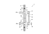
本発明の一実施の形態に係る回転杭1を構成する下鋼管3と上鋼管5の接合構造7(以下、単に「接合構造7」という)は、図1及び図2に示すように、下鋼管3の上端に取り付けられた第1外側継手管9と、上鋼管5の下端に取り付けられた第2外側継手管11と、第1外側継手管9の上端面と第2外側継手管11の下端面を当接させた状態で第1外側継手管9と第2外側継手管11の内周面側においてこれらを連結する内側継手部材13とを備えている。
以下に、各構成を詳細に説明する。
As shown in FIGS. 1 and 2, a joining structure 7 (hereinafter simply referred to as “joining
Below, each structure is demonstrated in detail.
<第1外側継手管9と第2外側継手管11>
第1外側継手管9と第2外側継手管11は、図1に示すように、接合する下鋼管3と上鋼管5の端部にそれぞれ溶接によって取り付けられている。
第1外側継手管9と第2外側継手管11の製造方法には、例えば鋼板を曲げ加工したリング又は鍛造・熱処理したリングを所定の形状に切削して製造する方法や、鋳造により製造する方法などがある。
<First outer
As shown in FIG. 1, the first outer
The manufacturing method of the first outer
第1外側継手管9の上端には接合端面15が、第2外側継手管11の下端には接合端面17が設けられおり、第1外側継手管9と第2外側継手管11は接合端面15と接合端面17を介して当接するようになっている。
接合端面15は、図2に示すように、杭軸直角方向に対して傾斜する螺旋斜面15aと、螺旋斜面15aに連続し杭軸直角方向に対して傾斜する支圧面15bとの組合せの複数からなり、接合端面15全体として略のこ歯状を形成している。
接合端面17も接合端面15と同様に、杭軸直角方向に対して傾斜する螺旋斜面17aと、螺旋斜面17aに連続し杭軸直角方向に対して傾斜する支圧面17bとの組合せの複数からなり、接合端面17全体として略のこ歯状を形成している。
A
As shown in FIG. 2, the joining
Similarly to the
螺旋斜面15a及び螺旋斜面17aは、回転杭1の貫入時の回転方向に対して登り斜面となる方向に設定されており、回転杭1が正回転したときに第1外側継手管9と第2外側継手管11が上下方向に離れるようになっている。なお、図1において正回転の方向を白抜き矢印で示す。
The
図5に第1外側継手管9と第2外側継手管11の展開図を示して接合端面15及び接合端面17の形状をより詳細に説明する。図5の展開図は、第1外側継手管9と第2外側継手管11の全周の展開図であるので、展開図の横幅は第1外側継手管9(第2外側継手管11)の周長に相当し、仮に第1外側継手管9(第2外側継手管11)の直径をD(mm)とすれば、横幅はπ×D(mm)である。
FIG. 5 shows a developed view of the first outer
図5に示すように、螺旋斜面15a(螺旋斜面17a)と支圧面15b(支圧面17b)は全周に亘って4つずつ設けられている。図5において、螺旋斜面15a(螺旋斜面17a)は杭軸直角方向に対してθ1傾斜する直線で表されており、支圧面15b(支圧面17b)は同様に杭軸直角方向に対してθ2傾斜する直線で表されている。また、図5において、ボルトやボルト孔の図示は省略している。
図5に示すように、接合端面15と接合端面17とが全周に亘って当接(面接触)するようになっている。
As shown in FIG. 5, four spiral inclined
As shown in FIG. 5, the joining
第1外側継手管9は内周面に内方向に突出する第1凸部21を有し、また第2外側継手管11は同じく内周面に内方に突出する第2凸部23を有している。第1外側継手管9と第2外側継手管11が接合端面15と接合端面17を介して当接すると、第1凸部21と第2凸部23が繋ぎ合わされて、円環状(図5の展開図においては帯状に表されている)の凸形を形成する。
The first outer
第1外側継手管9と第2外側継手管11の周面には、図1〜図4(主に図2及び図4参照)に示すように、内側継手部材13をボルトで締結するための複数のボルト孔27が周方向に所定間隔で設けられている。
ボルト孔27の内周面にはねじ加工がされており、頭部にねじ加工されたボルト25(図3参照、詳細は後述する)が挿入されて、その頭部と螺合可能になっている。なお、ボルト25で内側継手部材13を第1外側継手管9に締結した状態では、ボルト25の頭部が第1外側継手管9表面から突出しないようになっている。
第2外側継手管11には、外側から挿入されるボルトの頭部を格納するザグリ部29を有するボルト孔31が設けられており、ボルト締結後にボルトの頭部が継手表面から突出しないようになっている。
As shown in FIGS. 1 to 4 (mainly see FIGS. 2 and 4), the inner
The inner peripheral surface of the
The second outer
<内側継手部材>
内側継手部材13は、接合端面15と接合端面17を当接させた状態で第1外側継手管9と第2外側継手管11をその内周面側において連結して、回転杭1が正回転したときに第1外側継手管9と第2外側継手管11が離れようとするのに抵抗する部材である。
内側継手部材13は、図2に示すように、第1外側継手管9の第1凸部21と第2外側継手管11の第2凸部23に嵌合可能な凹部33を有する複数の円弧状部材からなる。
内側継手部材13は、例えば、鍛造・熱処理したリングの外周面を切削して凹部33を形成し、その後、該リングにスリットを入れて複数の部材に分割することで製造される。
<Inner joint member>
The inner
As shown in FIG. 2, the inner
The inner
複数の内側継手部材13を第1外側継手管9及び第2外側継手管11の内周面に配置した状態の一例を図6に示す。なお、内側継手部材13の配置が分かり易いように、図6において第1外側継手管9と第2外側継手管11を破線で示す。この例では4つの内側継手部材13が第1外側継手管9と第2外側継手管11の全内周に亘って配置されている(図6(b)参照)。
上述したとおり、第1外側継手管9と第2外側継手管11が当接状態において、第1凸部21と第2凸部23が繋ぎ合わされて円環状に凸形状になり、この円環凸形状に内側継手部材13の凹部33が嵌合している(図6(a)参照)。
An example of the state which has arrange | positioned the some inner
As described above, when the first outer
内側継手部材13には、図7に示すように、ボルト孔が上下2段に複数設けられており、下段に設けられたものが第1外側継手管9のボルト孔27に対応するボルト孔35であり、上段に設けられたものが第2外側継手管11のボルト孔31に対応するボルト孔37である。
ボルト孔35の内周面にねじ加工はなされておらず、ボルト25とナット39を用いて締結する。内側継手部材13の内側の面には、ナット39が収納されるザグリ孔41が設けられている。
他方、ボルト孔37の内周面はねじ加工がなされている。
なお、周方向のボルトの配置は、1つの内側継手部材13につき2〜5箇所とすることが望ましい。例えば、4つの内側継手部材13を用いる場合、各内側継手部材13の両端の上下をボルトで締結するようにすればよい。この場合、ボルト本数は全部で16本(4×2箇所×2段)となる。
As shown in FIG. 7, the inner
The inner peripheral surface of the
On the other hand, the inner peripheral surface of the
In addition, as for the arrangement | positioning of the volt | bolt of the circumferential direction, it is desirable to set it as 2-5 places per one inner
<ボルト>
図7に示すように、第1外側継手管9と内側継手部材13とを締結するには上述したようにボルト25及びナット39を用い、第2外側継手管11と内側継手部材13とを締結するには、六角穴43a付きのボルト43を用いる。ボルト25の頭部にはボルト25を回転させるための六角穴25aが設けられている。
<Bolt>
As shown in FIG. 7, in order to fasten the first outer
次に、以上のように構成された接合構造7における荷重(圧縮力、引張力、曲げモーメント、せん断力、正回転トルク)の伝達メカニズムについて概説する。
接合構造7に作用する圧縮力は、第1外側継手管9の接合端面15及び第2外側継手管11の接合端面17で伝達される。
引張力は、内側継手部材13の水平断面、第1外側継手管9の第1凸部21と第2外側継手管11の第2凸部23及び内側継手部材13の凹部33の支圧面及びせん断面で伝達される。
曲げモーメントは、上記の圧縮力と引張力の組合せで伝達される。
せん断力は、内側継手部材13の水平断面で伝達される。
正回転トルクは引張力の場合と同様である。
Next, the transmission mechanism of the load (compression force, tensile force, bending moment, shearing force, positive rotational torque) in the joining
The compressive force acting on the
The tensile force is determined by the horizontal cross section of the inner
The bending moment is transmitted by a combination of the compression force and the tensile force.
The shearing force is transmitted at the horizontal cross section of the inner
The positive rotational torque is the same as in the case of tensile force.
回転杭1の地盤中への回転貫入は、上鋼管5に正回転トルクを与え、該回転トルクによる水平力が下鋼管3に伝達されて、回転杭1全体が回転することで行われる。
回転杭1の回転貫入時における、上鋼管5から下鋼管3への荷重の伝達メカニズムについて図8に基づいて説明する。
図8(a)は、第1外側継手管9の接合端面15と第2外側継手管11の接合端面15、17が当接している状態を示しており、図8(b)は図8(a)における接合端面15及び接合端面17の展開図の一部を示したものである。
図8(b)において、力を白抜き矢印(力a、力b、力c、力d、力e、力f、力g)で示す。また、図8(b)において、矢印で示す各力が、第1外側継手管9と第2外側継手管11のいずれかに作用しているかを分かり易くするために、第1外側継手管9と第2外側継手管11同士を上下に離して図示している。
The rotation penetration of the rotary pile 1 into the ground is performed by applying a positive rotational torque to the
A mechanism for transmitting a load from the
FIG. 8A shows a state where the joining
In FIG. 8B, the force is indicated by white arrows (force a, force b, force c, force d, force e, force f, force g). Further, in FIG. 8B, in order to make it easy to understand whether each force indicated by an arrow acts on either the first outer
図8(a)の状態において、上鋼管5に回転トルクを作用させると、回転トルクによる力aは、上鋼管5に作用する螺旋斜面17aに沿う力bと、下鋼管3に作用する螺旋斜面15aに直交する力cに分力することができる。
そして、力bは回転方向の力dと上向きの力eに分力でき、また、力cも回転方向の力fと下向きの力gに分力できる。
このように、回転トルクによる力aの一部が杭軸方向の力(力e、力g)に変換され、これらの力は、接合端面15、17を上下に引き離そうとする力であるが、これらの力が第1外側継手管9の第1凸部21と第2外側継手管11の第2凸部23にせん断力及び支圧力として作用し、この力が内側継手部材13の凹部33にせん断力として作用し、最終的にはこの力が内側継手部材13に引張力として作用する。
引張強度はせん断強度よりも高いため、内側継手部材13に引張力として作用させることで接合構造全体としてのねじり耐力を効率的に向上させることができる。
When a rotational torque is applied to the
The force b can be divided into a rotational force d and an upward force e, and the force c can be divided into a rotational force f and a downward force g.
Thus, a part of the force a due to the rotational torque is converted into a force (force e, force g) in the pile axis direction, and these forces are forces that try to separate the joining end faces 15 and 17 up and down. These forces act on the first
Since the tensile strength is higher than the shear strength, the torsional strength of the entire joint structure can be efficiently improved by causing the inner
このように内側継手部材13は、接合構造全体のねじり耐力を向上させるための重要な役割を担っている。そのため、内側継手部材13の材料強度は、下鋼管3、上鋼管5、第1外側継手管9及び第2外側継手管11の材料強度よりも大きくすることが望ましい。逆に、第1外側継手管9及び第2外側継手管11の材料強度は、下鋼管3、上鋼管5と同じにすることができる。
Thus, the inner
このように、回転トルクを支圧力やせん断力ではなく鋼材を最も有効に使える引張力に構造的に変換することにより、継手寸法を小さく抑えつつ、下鋼管3及び上鋼管5に作用するトルク以上のねじり耐力を有する接合構造7とすることが可能である。
As described above, the rotational torque is structurally converted to the tensile force that can use the steel material most effectively instead of the supporting pressure and the shearing force, thereby suppressing the joint size to be small and more than the torque acting on the
なお、力d及び力fは第2外側継手管11、ひいては下鋼管3を回転させるトルクとして伝達され、回転杭1全体が回転貫入される。
また、杭施工時には逆回転をする場合もあり、そのときの回転トルクによる水平力hは、図9に示すように、支圧面15b及び支圧面17bに支圧及びせん断力として伝達される。逆回転時の回転トルクは、正回転時に比べれば小さいのでせん断力として伝達しても問題なく、また第1外側継手管9及び第2外側継手管11の全周長(せん断面45)を考慮することができるのでこの点でも問題ない。
The force d and the force f are transmitted as torque for rotating the second outer
Further, there is a case of reverse rotation at the time of pile construction, and the horizontal force h due to the rotational torque at that time is transmitted as a bearing pressure and a shearing force to the
本実施の形態の接合構造7は、回転トルクの一部を構造的に引張力に変換することができる。このときの変換率は、螺旋斜面15a及び螺旋斜面17aの傾斜角度θ1を変更することで調整することができる。
傾斜角度θ1は5°≦θ1≦45°に設定し、傾斜角度θ2は85°≦θ2≦90°に設定することが望ましい。この理由について以下に説明する。
The
The inclination angle θ 1 is desirably set to 5 ° ≦ θ 1 ≦ 45 °, and the inclination angle θ 2 is desirably set to 85 ° ≦ θ 2 ≦ 90 °. The reason for this will be described below.
傾斜角度θ1は、正回転時に滑り上がろうとする力を積極的に発生させるために45°以下とした。ただし、傾斜角度θ1が小さすぎると、内側継手部材13に引張力が伝達されずに第1外側継手管9及び第2外側継手管11がほぼ水平にねじられ、ボルトのみに大きなせん断力が作用してしまう。これを回避するために、ボルトに大きなせん断力が作用せず、かつ内側継手部材13に引張力が伝達される最小角度5°を、傾斜角度θ1の下限値とした。
The inclination angle θ 1 is set to 45 ° or less in order to positively generate a force to slide up during forward rotation. However, if the inclination angle θ 1 is too small, the first outer
一方、支圧面15b及び支圧面17bの傾斜角度θ2は、逆回転時の比較的小さな回転トルクを伝達できればよいため、角度を85°以上90°以下として、支圧面15b及び支圧面17bの支圧及びせん断により、回転トルクを伝達するようにした。
On the other hand, the inclination angle θ 2 of the bearing
次に、本実施の形態に係る接合構造7の標準的な接合手順として下記(1)〜(8)ついて、図10を参照しながら詳細に説明する。図10は、接合構造7の縦断面の左半分を図示したものである。
Next, the following (1) to (8) as a standard joining procedure of the joining
(1)下鋼管3の上端部(杭頭部)に第1外側継手管9を、上鋼管5の下端部に第2外側継手管11をそれぞれ工場溶接して取り付けておく。
(2)下鋼管3を地盤中に打設する(図10(a)参照)。
(3)ボルト25を、第1外側継手管9のボルト孔27に挿入し、さらに内側継手部材13のボルト孔35に挿入し、ナット39を締め付けることで第1外側継手管9に内側継手部材13を締結する(図10(b)参照)。
(1) The first outer
(2) The
(3) The
(4)ボルト25を回転して、ボルト25の頭部を内側にねじ込み、内側継手部材13を内方向に移動させる(図10(c)参照)。このとき、ナット39は、ザグリ孔41の中でボルト25の回転に伴って回転して、ボルト25とナット39と内側継手部材13間の相対距離が変わらない。内側継手部材13を内方向に移動させることで、上鋼管5を建て込んで第2外側継手管11を接合する際に、内側継手部材13が第2外側継手管11と緩衝せずに接合の妨げになることがない。
(4) The
(5)上鋼管5を建て込み、第2外側継手管11を内側継手部材13の外側に挿入し、接合端面15と接合端面17とを当接させる(図10(d)参照)。
(6)ボルト25を逆回転させて、内側継手部材13を外方向に移動させる。これにより、内側継手部材13の凹部33が、第1外側継手管9の第1凸部21及び第2外側継手管11の第2凸部23に嵌合する(図10(e)参照)。
(7)第2外側継手管11のボルト孔31にボルト43を挿入し、内側継手部材13のボルト孔37に螺入することで第2外側継手管11と内側継手部材13をボルト固定する(図10(f)参照)。
(8)最後に、下鋼管3及び上鋼管5のすべてのボルト頭部が継手表面から突出していないことを確認して、接合完了となる。
(5) The
(6) The
(7) The
(8) Finally, it is confirmed that all bolt heads of the
なお、下鋼管3の打設時に上端部(杭頭部)を養生可能ならば、上記(3)の内側継手部材13の取付け工程を上記(2)の前に行っておき、上記(2)の下鋼管3の打設完了後に上記(4)から作業するようにしてもよい。これにより、接合時間のさらなる短縮を図ることが可能となる。
If the upper end (pile head) can be cured at the time of placing the
また、上鋼管5の建て込み時に下端部を養生可能ならば、図11に示すように、ボルトやボルト孔等の配置と形状を図10に示すものの場合と全く逆にして、内側継手部材13を第2外側継手管11に取り付け、上鋼管5の建て込み後に下鋼管3の第1外側継手管9と内側継手部材13をボルト締結するようにしてもよい。
Further, if the lower end portion can be cured when the
下鋼管3側のボルト25の頭部をねじ加工にしているのは、上鋼管5を建て込む際に、内側継手部材13を内方向に移動させて上鋼管5を建て込み、再び外方向に移動させるまでの間(上記(4)〜(6)参照)、内側継手部材13を垂直に保持するためである。
したがって、接合する下鋼管3及び上鋼管5が小径で内側継手部材13が小さい場合など、内側継手部材13の保持に支障がなければ、図12(b)に示すように、ボルトを下鋼管3及び上鋼管5側とも軸部のみがねじ加工が施された通常の六角穴47a付きのボルト47とし、ボルト孔等もそれに対応するもの(ザグリ孔49、ボルト孔50、ボルト孔51)でもよい。この場合、ボルト47の回転量を調整することで、図12(a)に示すように、内側継手部材13を内方向へ移動可能である。
The head of the
Therefore, when the
また、ボルト47の頭部が継手表面から突出していても施工上、杭の周面摩擦力への影響がない場合では、図13に示すように、ザグリ孔を設けなくともよい。
Further, when the head portion of the
以上のように、本実施の形態においては、回転トルクを支圧やせん断ではなく鋼材を最も有効に使える引張に構造的に変換し、発生した引張力を内側継手部材13で受けることにより、継手寸法を抑えつつ、下鋼管3及び上鋼管5の全強トルク以上の大きな回転トルクに対応でき、回転杭1の正回転、逆回転を考慮した合理的な接合構造7とすることができる。
また、ボルトの頭部が継手表面から突出しないようになっているので、回転貫入時の抵抗をなくすことができ、回転杭1の周面摩擦力への影響を低減できる。
As described above, in the present embodiment, the rotational torque is structurally converted to tension that can use the steel material most effectively instead of bearing pressure or shear, and the generated tensile force is received by the inner
Moreover, since the head part of the bolt does not protrude from the joint surface, the resistance at the time of rotation penetration can be eliminated, and the influence on the circumferential frictional force of the rotary pile 1 can be reduced.
なお、上記では、傾斜角度θ2が90°である例について説明したが、図14に示すように傾斜角度θ2を小さく設定して支圧面15b及び支圧面17bの傾きを比較的緩やかにしてもよい。より好ましくは、上述したとおり85°≦θ2≦90°に設定する。
また、凸凹部11は、図5に示す形状の他、嵌合性を向上させるために、図15に示すように螺旋斜面15aと支圧面15bの交差部、及び螺旋斜面17aと支圧面17bの交差部にアールを形成するようにしてもかまわない。
In the above description, the example in which the inclination angle θ 2 is 90 ° has been described. However, as shown in FIG. 14, the inclination angle θ 2 is set small, and the inclinations of the bearing
In addition to the shape shown in FIG. 5, the
さらに、第1外側継手管9と第2外側継手管11の位置決めや芯合わせが容易となるように、図16に示すように第2外側継手管11の支圧面17bに溝部53を設け、第1外側継手管9の支圧面15bに、溝部53が挿入される凸条部55を設けてもよい。第1外側継手管9の上面視を図17に示す。なお、溝部53の形状は図18(a)〜(c)に示すようなものでもよい。
Further, as shown in FIG. 16, a
本発明の鋼管杭の接合構造の一設計例を示す。
外径φ609.6mm×板厚t12mmの鋼管杭(SKK400)に対して本発明の接合構造を設計した場合、例えば以下のようになる。
・第1外側継手管及び第2外側継手管:外径φ609.6mm×板厚t12mm(凸型増厚部はt25mm)×長さL70mm(同L35mm)、凸凹部は4つ、傾斜角度θ1は5°、傾斜角度θ2は90°、材質はSM400A
・内側継手部材:外径φ585.6(凹型円弧部はφ559.6mm)×板厚t23mm(同t10mm)×長さL110mm(同L70mm)、4分割、材質はHITEN780
・六角穴付きボルト:M12、本数は24本(4分割×3箇所×2段)
The design example of the joining structure of the steel pipe pile of this invention is shown.
When the joint structure of the present invention is designed for a steel pipe pile (SKK400) having an outer diameter φ609.6 mm × plate thickness t12 mm, for example, the following is obtained.
-1st outer joint pipe and 2nd outer joint pipe: Outer diameter φ609.6mm x Plate thickness t12mm (convex thickened part is t25mm) x length L70mm (same L35mm), four convex concave parts, inclination angle θ 1 Is 5 °, inclination angle θ 2 is 90 °, material is SM400A
・ Inner joint member: Outer diameter φ585.6 (concave arc part is φ559.6mm) x plate thickness t23mm (same t10mm) x length L110mm (same L70mm), divided into 4 parts, material is HITEN780
-Hexagon socket head cap bolt: M12, 24 bolts (4 divisions x 3 locations x 2 stages)
a、b、c、d、e、f、g、h 力
1 回転杭
3 下鋼管
5 上鋼管
7 接合構造
9 第1外側継手管
11 第2外側継手管
13 内側継手部材
15 接合端面
15a 螺旋斜面
15b 支圧面
17 接合端面
17a 螺旋斜面
17b 支圧面
19 支圧面
21 第1凸部
23 第2凸部
25 ボルト
25a 六角穴
27 ボルト孔
29 ザグリ部
31 ボルト孔
33 凹部
35 ボルト孔
37 ボルト孔
39 ナット
41 ザグリ孔
43 ボルト
43a 六角穴
45 せん断面
47 ボルト
47a 六角穴
49 ザグリ孔
50 ボルト孔
51 ボルト孔
53 溝部
55 凸条部
a, b, c, d, e, f, g, h force 1
Claims (3)
下側の鋼管の上端に取り付けられた第1外側継手管と、上側の鋼管の下端に取り付けられた第2外側継手管と、前記第1外側継手管の上端面と前記第2外側継手管の下端面を当接させた状態で前記第1外側継手管と前記第2外側継手管の内周面側においてこれらを連結する内側継手部材とを備え、
前記第1外側継手管と前記第2外側継手管は、前記回転杭が正回転したときに両者が上下方向に離れる方向となる複数の螺旋斜面を有する接合端面を介して当接し、前記内側継手部材は前記第1外側継手管と前記第2外側継手管が離れようとするのに抵抗するようになっており、
前記第1外側継手管及び前記第2外側継手管の接合端面は、前記螺旋斜面に連続する支圧面を有し、
前記螺旋斜面の杭軸直角方向に対する傾斜角度をθ 1 、前記支圧面の杭軸直角方向に対する傾斜角度をθ 2 とすると、5°≦θ 1 ≦45°、85°≦θ 2 ≦90°に設定されていることを特徴とする回転杭を構成する鋼管の接合構造。 A joining structure for joining the upper and lower steel pipes constituting the rotating pile,
A first outer joint pipe attached to the upper end of the lower steel pipe, a second outer joint pipe attached to the lower end of the upper steel pipe, an upper end surface of the first outer joint pipe, and the second outer joint pipe An inner joint member for connecting the first outer joint pipe and the second outer joint pipe on the inner peripheral surface side in a state where the lower end surface is in contact with each other;
The first outer joint pipe and the second outer joint pipe are in contact with each other through joint end surfaces having a plurality of spiral slopes that are separated in the vertical direction when the rotary pile rotates forward, and the inner joint The member is adapted to resist the separation of the first outer joint pipe and the second outer joint pipe .
The joining end faces of the first outer joint pipe and the second outer joint pipe have a bearing surface that is continuous with the spiral slope,
When the inclination angle of the spiral slope with respect to the direction perpendicular to the pile axis is θ 1 , and the inclination angle of the bearing surface with respect to the direction perpendicular to the pile axis is θ 2 , 5 ° ≦ θ 1 ≦ 45 °, 85 ° ≦ θ 2 ≦ 90 ° A steel pipe joint structure constituting a rotating pile characterized by being set .
Priority Applications (1)
| Application Number | Priority Date | Filing Date | Title |
|---|---|---|---|
| JP2013117462A JP6007863B2 (en) | 2013-06-04 | 2013-06-04 | Joint structure of steel pipes constituting rotating piles |
Applications Claiming Priority (1)
| Application Number | Priority Date | Filing Date | Title |
|---|---|---|---|
| JP2013117462A JP6007863B2 (en) | 2013-06-04 | 2013-06-04 | Joint structure of steel pipes constituting rotating piles |
Publications (2)
| Publication Number | Publication Date |
|---|---|
| JP2014234654A JP2014234654A (en) | 2014-12-15 |
| JP6007863B2 true JP6007863B2 (en) | 2016-10-12 |
Family
ID=52137564
Family Applications (1)
| Application Number | Title | Priority Date | Filing Date |
|---|---|---|---|
| JP2013117462A Active JP6007863B2 (en) | 2013-06-04 | 2013-06-04 | Joint structure of steel pipes constituting rotating piles |
Country Status (1)
| Country | Link |
|---|---|
| JP (1) | JP6007863B2 (en) |
Families Citing this family (1)
| Publication number | Priority date | Publication date | Assignee | Title |
|---|---|---|---|---|
| KR102508176B1 (en) * | 2021-12-20 | 2023-03-10 | 주식회사 이도구조엔지니어링 | Improved coupler connection structure of helical piles |
Family Cites Families (3)
| Publication number | Priority date | Publication date | Assignee | Title |
|---|---|---|---|---|
| JPH09287135A (en) * | 1996-04-22 | 1997-11-04 | Kubota Corp | Columnar body and joint connecting columnar body |
| JP3902637B2 (en) * | 2000-10-18 | 2007-04-11 | 旭化成建材株式会社 | Pile fastening structure and fastener |
| JP2012162947A (en) * | 2011-02-08 | 2012-08-30 | Toyota Home Kk | Steel pipe pile |
-
2013
- 2013-06-04 JP JP2013117462A patent/JP6007863B2/en active Active
Also Published As
| Publication number | Publication date |
|---|---|
| JP2014234654A (en) | 2014-12-15 |
Similar Documents
| Publication | Publication Date | Title |
|---|---|---|
| US10458090B2 (en) | Soil displacement piles | |
| US20160186402A1 (en) | Helical pile assembly with top plate | |
| JP4645268B2 (en) | Joint structure of steel pipe pile for landslide prevention and steel pipe pile for landslide prevention provided with the same | |
| PH12015500437B1 (en) | End plate for concrete piles | |
| JP2007063806A (en) | Screw joint structure of metal tube | |
| JP5053828B2 (en) | Joint structure | |
| JP2009299298A (en) | Mechanical joint of steel pipe pile | |
| JP5310198B2 (en) | Steel pipe joint structure | |
| JP4115463B2 (en) | Fitting device | |
| JP6007863B2 (en) | Joint structure of steel pipes constituting rotating piles | |
| JP4474430B2 (en) | Pile joint structure | |
| JP2013112953A (en) | Steel pipe pile connection structure | |
| KR101448145B1 (en) | Column Integrated Footing | |
| JP2015183388A (en) | Steel pipe connection structure and steel pipe connection method | |
| JP6243814B2 (en) | Steel pipe pile joint structure | |
| KR101759879B1 (en) | Rotational penetration pile unit, rotational penetration pile and construction method thereof | |
| JP2009024436A (en) | Mechanical joint of steel pipe pile | |
| TWI607130B (en) | Pile of welded joints | |
| JP3169245U (en) | Fitting device | |
| JP5756425B2 (en) | Construction method of screw type rotary penetration pile and ground improvement pile | |
| JP6470699B2 (en) | Pile connection structure | |
| JP4854607B2 (en) | Segment joint structure | |
| JP3568528B1 (en) | Rotating device for steel pipe pile | |
| JP6410595B2 (en) | Connecting member, connecting member unit, and connecting method | |
| JP7420123B2 (en) | Threaded joints, steel pipes with threaded joints, structures, construction methods for structures, landslide prevention piles, construction methods for landslide prevention piles, design methods for threaded joints, manufacturing methods for threaded joints, manufacturing methods for steel pipes with threaded joints |
Legal Events
| Date | Code | Title | Description |
|---|---|---|---|
| A621 | Written request for application examination |
Free format text: JAPANESE INTERMEDIATE CODE: A621 Effective date: 20150123 |
|
| A977 | Report on retrieval |
Free format text: JAPANESE INTERMEDIATE CODE: A971007 Effective date: 20151015 |
|
| A131 | Notification of reasons for refusal |
Free format text: JAPANESE INTERMEDIATE CODE: A131 Effective date: 20151020 |
|
| A521 | Request for written amendment filed |
Free format text: JAPANESE INTERMEDIATE CODE: A523 Effective date: 20151214 |
|
| A02 | Decision of refusal |
Free format text: JAPANESE INTERMEDIATE CODE: A02 Effective date: 20160412 |
|
| A521 | Request for written amendment filed |
Free format text: JAPANESE INTERMEDIATE CODE: A523 Effective date: 20160706 |
|
| A911 | Transfer to examiner for re-examination before appeal (zenchi) |
Free format text: JAPANESE INTERMEDIATE CODE: A911 Effective date: 20160713 |
|
| TRDD | Decision of grant or rejection written | ||
| A01 | Written decision to grant a patent or to grant a registration (utility model) |
Free format text: JAPANESE INTERMEDIATE CODE: A01 Effective date: 20160816 |
|
| A61 | First payment of annual fees (during grant procedure) |
Free format text: JAPANESE INTERMEDIATE CODE: A61 Effective date: 20160829 |
|
| R150 | Certificate of patent or registration of utility model |
Ref document number: 6007863 Country of ref document: JP Free format text: JAPANESE INTERMEDIATE CODE: R150 |
|
| R250 | Receipt of annual fees |
Free format text: JAPANESE INTERMEDIATE CODE: R250 |
|
| R250 | Receipt of annual fees |
Free format text: JAPANESE INTERMEDIATE CODE: R250 |
|
| R250 | Receipt of annual fees |
Free format text: JAPANESE INTERMEDIATE CODE: R250 |