JP6004182B2 - Front pillar air noise reduction structure - Google Patents
Front pillar air noise reduction structure Download PDFInfo
- Publication number
- JP6004182B2 JP6004182B2 JP2013022441A JP2013022441A JP6004182B2 JP 6004182 B2 JP6004182 B2 JP 6004182B2 JP 2013022441 A JP2013022441 A JP 2013022441A JP 2013022441 A JP2013022441 A JP 2013022441A JP 6004182 B2 JP6004182 B2 JP 6004182B2
- Authority
- JP
- Japan
- Prior art keywords
- pillar
- windshield
- height
- ridge
- noise reduction
- Prior art date
- Legal status (The legal status is an assumption and is not a legal conclusion. Google has not performed a legal analysis and makes no representation as to the accuracy of the status listed.)
- Active
Links
Images


Classifications
-
- B—PERFORMING OPERATIONS; TRANSPORTING
- B62—LAND VEHICLES FOR TRAVELLING OTHERWISE THAN ON RAILS
- B62D—MOTOR VEHICLES; TRAILERS
- B62D35/00—Vehicle bodies characterised by streamlining
- B62D35/008—Side spoilers
-
- B—PERFORMING OPERATIONS; TRANSPORTING
- B62—LAND VEHICLES FOR TRAVELLING OTHERWISE THAN ON RAILS
- B62D—MOTOR VEHICLES; TRAILERS
- B62D25/00—Superstructure or monocoque structure sub-units; Parts or details thereof not otherwise provided for
- B62D25/04—Door pillars ; windshield pillars
-
- B—PERFORMING OPERATIONS; TRANSPORTING
- B62—LAND VEHICLES FOR TRAVELLING OTHERWISE THAN ON RAILS
- B62D—MOTOR VEHICLES; TRAILERS
- B62D35/00—Vehicle bodies characterised by streamlining
Description
本発明は、車両のフロントピラー部における空気騒音低減構造に関する。 The present invention relates to an air noise reduction structure in a front pillar portion of a vehicle.
居住性やコンパクト性に重点をおいた小型車両等では、フロントピラーやウインドシールドの立ち上がり角が大きく設定される。車両走行時にウインドシールドが受ける前方からの空気流はルーフ側や両サイドに流れるが、フロントピラーやウインドシールドが立っている場合には、フロントピラーから車体側部に回り込む傾向が顕著になる。 In small vehicles that place emphasis on comfort and compactness, the rising angle of the front pillar and windshield is set large. The airflow from the front received by the windshield when the vehicle is traveling flows to the roof side and both sides. However, when the front pillar and the windshield are standing, the tendency to go around from the front pillar to the vehicle body side becomes remarkable.
その際、フロントピラー部では、車幅方向への空気流がウインドシールドからの段差を越えて急激に後方へ偏向される過程で車体表面から剥離し、車体側部に渦流が発生する。この渦流は車体側部の後方への主流とぶつかる際に空気騒音を発生する。この位置の空気騒音が問題となるのは運転席や助手席に近いという理由にもよる。 At that time, in the front pillar portion, the air flow in the vehicle width direction peels off from the surface of the vehicle body in the process of suddenly deflecting backward beyond the step from the windshield, and a vortex flow is generated on the side portion of the vehicle body. This eddy current generates air noise when it collides with the mainstream behind the side of the vehicle body. The air noise at this position is a problem because it is close to the driver's seat and front passenger seat.
渦流を低減するためには、フロントピラーの断面形状を流れに適合させることやフロントピラーの周回に導風板を設けることなども想定される。しかし、フロントピラーは衝突時の荷重吸収やキャビン剛性、運転者の視界確保など、様々な条件を満たす必要があるため、空気流だけを目的として形状設計することはできない。例えば、空気の流れを良くするためにフロントピラーを太く・流線型にすれば運転者の視界は悪化する。 In order to reduce the eddy current, it is assumed that the cross-sectional shape of the front pillar is adapted to the flow, and a wind guide plate is provided around the front pillar. However, since the front pillar needs to satisfy various conditions such as load absorption at the time of collision, cabin rigidity, and ensuring the driver's visibility, it cannot be designed for the purpose of airflow alone. For example, if the front pillar is made thick and streamlined to improve the air flow, the driver's field of view deteriorates.
一方、小型車両でもフロントピラーやウインドシールドの立ち上がり角が小さく設定される場合、すなわち傾斜が大きく設定される場合もある(特許文献1参照)。このような車両では、車体側部への空気の回り込みは少ないので、上述したように空気騒音は小さく、逆にウインドシールドからフロントピラー部への段差を大きくして車体側部への空気の回り込み自体を抑えてしまうことも可能であるが、ウインドシールドの立ち上がり角が大きい車両では、このような対策を講じることはできない。 On the other hand, even in a small vehicle, there are cases where the rising angle of the front pillar or the windshield is set small, that is, the inclination is set large (see Patent Document 1). In such a vehicle, since the air wraps around the side of the vehicle body is small, the air noise is small as described above, and conversely, the air wraps around the vehicle body side by increasing the step from the windshield to the front pillar. Although it is possible to suppress this, such a measure cannot be taken in a vehicle having a large windshield rising angle.
本発明はこのような実状に鑑みてなされたものであって、その目的は、ウインドシールドの立ち上がり角が大きい車両のフロントピラー部における空気騒音を低減するための構造を提供することにある。 The present invention has been made in view of such a situation, and an object thereof is to provide a structure for reducing air noise in a front pillar portion of a vehicle having a large rising angle of a windshield.
上記従来技術の有する課題を解決するため、本発明は、
ウインドシールドの両側縁に沿って上下に延在するフロントピラーの空気騒音低減構造であって、前記フロントピラーが、前記ウインドシールドの両側から前記ウインドシールドの厚さ方向に立ち上がる縦壁面と、前記縦壁面の前端に沿って延在するピラー稜部と、前記ピラー稜部の後側方に沿って延在し車体表面の一部を画成するピラー表面と、を備え、水平方向に対して50度以上の立ち上がり角を有しており、前記縦壁面に沿った前記ウインドシールド両側縁の表面側に貼付されたピラーモールを備えるものにおいて、
前記ピラーモールは、長手方向と直交する断面形状が略四角形状をなし、前記縦壁面から前端縁までの幅(Lm)が、前記ウインドシールド表面を基準にした前記ピラー稜部の高さ(H)の1.5〜3倍の範囲にあり、かつ、前記前端縁までの幅(Lm)に対する前記前端縁の高さ(Hm)の比(Hm/Lm)が0.2〜0.4の範囲にあることを特徴とするフロントピラーの空気騒音低減構造にある。
In order to solve the above-described problems of the prior art, the present invention provides:
An air noise reduction structure for a front pillar extending vertically along both side edges of the windshield, wherein the front pillar rises from both sides of the windshield in the thickness direction of the windshield, and the vertical pillar A pillar ridge extending along the front end of the wall surface, and a pillar surface extending along the rear side of the pillar ridge and defining a part of the surface of the vehicle body. Having a rising angle of at least degrees, and comprising pillar moldings attached to the surface sides of both side edges of the windshield along the vertical wall surface,
The pillar molding has a substantially square cross-sectional shape perpendicular to the longitudinal direction, and the width (Lm) from the vertical wall surface to the front end edge is the height of the pillar ridge portion (H) with respect to the windshield surface (H ) And the ratio (Hm / Lm) of the height (Hm) of the front edge to the width (Lm) to the front edge is 0.2 to 0.4. The air noise reduction structure of the front pillar is characterized by being in the range.
本発明は、上記構成により、以下に記載されるような効果を奏する。
ウインドシールド両側縁に貼付されたピラーモールが略四角形状の断面をなすことにより、車両走行時にウインドシールドに沿って側方に流れる空気流がピラー稜部に到達する以前にピラーモールの前端縁で偏向され、ピラーモールの幅の範囲内において前方からの空気流と合流する。このとき、ピラーモールの前端縁がピラー稜部に対して上記範囲で規定されるような位置にあると、前記偏向されかつ合流した空気流がフロントピラーの縦壁面に衝突せずにピラー稜部を通過し、ピラー表面に沿って車体側部後方に流れるので、ピラー表面からの剥離や渦流の発生による空気騒音が抑制される。
According to the above configuration, the present invention has the following effects.
The pillar moldings affixed to both side edges of the windshield have a substantially square cross section, so that the airflow that flows laterally along the windshield when the vehicle travels before the pillar edge reaches the pillar ridge. It is deflected and merges with the air flow from the front within the width of the pillar molding. At this time, if the front end edge of the pillar molding is in a position defined by the above range with respect to the pillar ridge, the deflected and merged air flow does not collide with the vertical wall surface of the front pillar, and the pillar ridge , And flows behind the side of the vehicle body along the pillar surface, so that air noise due to separation from the pillar surface and generation of eddy currents is suppressed.
なお、縦壁面から前端縁までの幅(Lm)が、ウインドシールド表面を基準にしたピラー稜部の高さ(H)の1.5倍より小さい場合や、前端縁までの幅(Lm)に対する前端縁の高さ(Hm)の比(Hm/Lm)が0.2より小さい場合には、ピラー稜部を越える空気流を形成することが困難である。逆に、縦壁面から前端縁までの幅(Lm)が、ウインドシールド表面を基準にしたピラー稜部の高さ(H)の3倍より大きい場合や、前端縁までの幅(Lm)に対する前端縁の高さ(Hm)の比(Hm/Lm)が0.4より大きい場合には、空気抵抗が大きくなり風切り音の低減に寄与しないうえ、運転者の視界への影響も無視できなくなる。 It should be noted that the width (Lm) from the vertical wall surface to the front edge is smaller than 1.5 times the height (H) of the pillar ridge with respect to the windshield surface, or the width (Lm) to the front edge. When the ratio (Hm / Lm) of the height (Hm) of the front end edge is smaller than 0.2, it is difficult to form an air flow exceeding the pillar ridge. Conversely, when the width (Lm) from the vertical wall surface to the front edge is greater than three times the height (H) of the pillar ridge relative to the windshield surface, or the front edge relative to the width (Lm) to the front edge When the ratio (Hm / Lm) of the edge height (Hm) is greater than 0.4, the air resistance increases and does not contribute to the reduction of wind noise, and the influence on the driver's view cannot be ignored.
また、ピラーモールが略四角形状の断面を有し前端縁を有することによって、空気流を単に偏向させるのみならず、微細な乱流を発生させ当該部分における剥離を防止できる点からも有利である。因みに、湾曲した断面形状では、空気流に対する充分な偏向作用が得られず、空気騒音の低減効果は得られない。 In addition, the pillar molding has a substantially square cross section and has a front end edge, which is advantageous not only for deflecting the air flow but also for generating fine turbulence and preventing separation at the portion. . Incidentally, with a curved cross-sectional shape, a sufficient deflection action against the air flow cannot be obtained, and the effect of reducing the air noise cannot be obtained.
本発明において、前記前端縁の高さ(Hm)が前記ピラー稜部の高さ(H)以下であることが好適である。ピラーモールは付加物であるため極力小さい方が好ましいのは勿論であるが、ピラー稜部の高さを越えてしまうと後端側に剥離や渦流を発生し騒音低減にも寄与しない。運転者の視界確保という点からも極力小さい方が好ましい。 In the present invention, it is preferable that the height (Hm) of the front edge is equal to or less than the height (H) of the pillar ridge. Since the pillar molding is an addition, it is of course preferable that the pillar molding is as small as possible. However, if the height of the pillar ridge is exceeded, separation or vortex flow is generated on the rear end side, which does not contribute to noise reduction. From the viewpoint of ensuring the driver's field of view, it is preferable to make it as small as possible.
また、本発明において、前記ウインドシールドの両側縁の下端から上端に向かうに従って前記縦壁面から前記前端縁までの幅(Lm)が減少していても良い。ウインドシールドからフロントピラーを横切って車体側方に流れる空気流はフロントピラーの下方ほど顕著であるので、ウインドシールドの全長に亘って一様な断面積を有する必要はなく、空気流の程度に応じて幅を減じることで、空気抵抗の低減や運転者の視界確保という点でも有利である。 Moreover, in this invention, the width | variety (Lm) from the said vertical wall surface to the said front end edge may reduce as it goes to the upper end from the lower end of the both-sides edge of the said windshield. The airflow that flows from the windshield across the front pillar to the side of the vehicle body is more conspicuous as the lower part of the front pillar, so it is not necessary to have a uniform cross-sectional area over the entire length of the windshield, depending on the degree of airflow Reducing the width is also advantageous in reducing air resistance and securing the driver's field of view.
以下、本発明の実施の形態について、図面を参照しながら詳細に説明する。
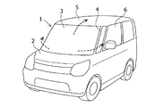
図1は、本発明の空気騒音低減構造が実施される典型的な車両1を示しており、車両1は、前部にボンネット2(エンジンフード)を有する小型乗用車であり、乗員室のスペースを確保するために、立ち上がり角が大きいウインドシールド3およびフロントピラー4を備えている。
Hereinafter, embodiments of the present invention will be described in detail with reference to the drawings.
FIG. 1 shows a typical vehicle 1 in which the air noise reduction structure of the present invention is implemented. The vehicle 1 is a small passenger car having a hood 2 (engine hood) at the front, and the space in the passenger compartment is shown. In order to ensure, a
このような車両1では、走行時にウインドシールド3が前方から受ける空気流は、ウインドシールド3の傾斜に案内されてルーフ5側に、あるいは、ウインドシールド3の湾曲に案内されて車体側部6側に流れるが、図示例のように、フロントピラー4やウインドシールド3が立っている場合には、フロントピラー4から車体側部6に回り込む傾向が顕著になることは既に述べた通りである。
In such a vehicle 1, the airflow received by the
その際、フロントピラー4付近では、図4に示すように、ウインドシールド3に沿って車幅方向に向かう空気流が、フロントピラー4の縦壁面42(稜部Q)を越えたところで、車体側部に沿って後方に流れる空気流と衝突し、急激に後方へ偏向される過程でピラー表面41から剥離し渦流が発生する。これが騒音源となることも既に述べた。したがって、このような空気流の剥離と渦流を抑制すれば空気騒音を低減できる。なお、ウインドシールド3は、フロントピラー4の支持面43にウインドシールド固定用緩衝材7を介して支持されている。
At that time, in the vicinity of the
ここで、図4において、仮に、ピラー表面(41)が稜部Qから空気流の流線に適合するような円弧状断面を有していれば、すなわち、稜部Qに続くピラー表面(41)がウインドシールド3と略平行になるように、稜部Qが90度近い角度を有していれば、剥離や渦流の発生が低減されるものと予測されるが、居住性を極限まで追求した車両1では、ピラー表面41は車体側面に沿い稜部Qは鋭角的に形成されており、上記形状の採用は内側にウインドシールド3の視野を狭めることになる。
Here, in FIG. 4, if the pillar surface (41) has an arcuate cross section that fits the streamline of the air flow from the ridge Q, that is, the pillar surface (41 following the ridge Q). If the ridge part Q has an angle close to 90 degrees so that it is substantially parallel to the
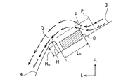
そこで、本発明では、図2及び図3に示すように、フロントピラー4に隣接したウインドシールド3の表面にピラーモール8を貼付し、その形状を工夫することで、ウインドシールド3の視野を狭めることなく空気騒音低減効果を得ている。各図において、ピラーモール8は、ウインドシールド3の両側縁に沿って上下に延在し、長手方向に一様な長方形断面をなしており、起立した前端縁Pを有している。
Therefore, in the present invention, as shown in FIGS. 2 and 3, the
ピラーモール8は、フロントピラー4の縦壁面42に接していても良いし、図示例のように間隙を有して貼付されても良いが、フロントピラー4の稜部Qの高さHに対して前端縁Pの位置(Lm,Hm)が、以下に述べる範囲内にある場合に顕著な空気騒音低減効果を得られることが風洞実験などで確認されている。すなわち、ウインドシールド表面を基準にしたフロントピラー4の稜部Q(縦壁面42)から前端縁Pまでの幅(Lm)、前端縁の高さ(Hm)、稜部Qの高さ(H)において、
1.5≦Lm/H≦3,かつ,0.2≦Hm/Lm≦0.4
の範囲にある。
The
1.5 ≦ Lm / H ≦ 3 and 0.2 ≦ Hm / Lm ≦ 0.4
It is in the range.
上記は、換言すれば、前端縁Pまでの幅(Lm)は稜部Qの高さ(H)の1.5〜3倍の範囲にあり、かつ、前端縁Pまでの幅(Lm)に対する前端縁Pの高さ(Hm)の比(Hm/Lm)が0.2〜0.4の範囲にある場合ということになる。このような前端縁Pの取りうる範囲(PL、PH)を図5に示す。概ねピラーモール8の幅(Lm)が大きくなるほど、前端縁Pの高さ(Hm)も大きくなる傾向にある。
In other words, the width (Lm) to the front edge P is in the range of 1.5 to 3 times the height (H) of the ridge Q, and the width (Lm) to the front edge P is This means that the ratio (Hm / Lm) of the height (Hm) of the front edge P is in the range of 0.2 to 0.4. The possible range (PL, PH) of the front edge P is shown in FIG. Generally, as the width (Lm) of the
図3に示すように、ウインドシールド3の表面に沿って側方に流れる空気流は、フロントピラー4の縦壁面42に到達する以前にピラーモール8の前端縁Pでウインドシールド3から離れる方向に偏向され、前端縁Pを越えると前方からの空気流と合流して側方ないしは後方に流れるが、ピラーモール8の前端縁Pの位置(Lm,Hm)が上記範囲にある場合には、偏向されかつ合流した空気流がフロントピラー4の縦壁面42に衝突せずに稜部Qを通過し、ピラー表面41に沿って車体側部後方に流れる。そのため、ピラー表面41からの剥離や渦流の発生が抑制され、空気騒音が低減される。
As shown in FIG. 3, the airflow that flows laterally along the surface of the
なお、縦壁面42から前端縁Pまでの幅(Lm)が稜部Qの高さ(H)の1.5倍より小さい場合や、前端縁Pまでの幅(Lm)に対する前端縁Pの高さ(Hm)の比(Hm/Lm)が0.2より小さい場合には、稜部Qを越える空気流を形成することが困難である。逆に、縦壁面42から前端縁Pまでの幅(Lm)が稜部Qの高さ(H)の3倍より大きい場合や、前端縁Pまでの幅(Lm)に対する高さ(Hm)の比(Hm/Lm)が0.4より大きい場合には、空気抵抗が大きくなり空気騒音の低減にも寄与しない。
The width (Lm) from the
フロントピラーの立ち上がり角=50度の車両を使用して風洞実験を行ったところ、稜部Qの高さ(H)=10mmに対し、(i)ピラーモール高さ(Hm)=5mm、前端縁Pまでの幅(Lm)=18mm(ピラーモール幅15mm、縦壁面との間隔3mm)の場合、および、(ii)ピラーモール高さ(Hm)=10mm、前端縁Pまでの幅(Lm)=28mm(ピラーモール幅25mm、縦壁面との間隔3mm)の場合に良好な騒音低減効果が確認された。
When a wind tunnel experiment was conducted using a vehicle with a front pillar rising angle = 50 degrees, the height of the ridge Q (H) = 10 mm, while (i) the pillar mall height (Hm) = 5 mm, the front edge In the case of the width to L (Lm) = 18 mm (pillar molding width 15 mm, spacing 3 mm from the vertical wall surface), and (ii) pillar molding height (Hm) = 10 mm, the width to the front edge P (Lm) = A good noise reduction effect was confirmed in the case of 28 mm (pillar molding width 25 mm,
また、ピラーモール8の断面形状について、図2〜3に示す実施形態では角形の前端縁Pを有する四角形状をなすことによって、空気流を単に偏向させるのみならず、微細な乱流を発生させ当該部分における剥離を防止できることが実験で確認されている。比較のために、上述したのと同じ幅および高さで湾曲した断面形状を有するピラーモールで実験を行ったところ、空気流に対する充分な偏向作用が得られず、空気騒音の低減効果は認められなかった。
In addition, regarding the cross-sectional shape of the
一方、ピラーモール8の前端縁Pが稜部Qの高さ(H)よりも低い場合には、前記稜部Qの高さ(H)を越えない範囲で、ピラーモール8の上面が、稜部Qに隣接した後端縁側において前端縁Pより高くなる傾斜を有していても良い。
On the other hand, when the front end edge P of the
ピラーモール8の材質は特に限定されるものではないが、剥離を防止して空気抵抗および空気騒音を低減するうえでは、表面の硬度と平滑度が適度に抑えられたスポンジなどの合成発泡樹脂材が有利である。硬質な材料で構成する場合に比べて空気騒音の周波数が低減される。この場合、ピラーモール8の表面をスポンジで構成して内実部を別材料で構成することもできる。
The material of the
以上、本発明の実施の形態について述べたが、本発明は上記各実施形態に限定されるものではなく、本発明の技術的思想に基づいてさらに各種の変形および変更が可能である。
例えば、上記実施形態では、ピラーモール8の幅(Lm)や高さ(Hm)が長さ方向に一様である場合を示したが、ウインドシールド3の下端から上端に向かうに従ってピラーモール8の幅(Lm)および/または高さ(Hm)が減少していても良い。
As mentioned above, although embodiment of this invention was described, this invention is not limited to said each embodiment, Based on the technical idea of this invention, a various deformation | transformation and change are further possible.
For example, in the said embodiment, although the width | variety (Lm) and height (Hm) of the
1 車両
2 ボンネット(エンジンフード)
3 ウインドシールド
4 フロントピラー
8 ピラーモール
41 ピラー表面
42 縦壁面
P 前端縁
Q 稜部
1
3
Claims (3)
前記ピラーモールは、長手方向と直交する断面形状が略四角形状をなし、前記縦壁面から前端縁までの幅(Lm)が、前記ウインドシールド表面を基準にした前記ピラー稜部の高さ(H)の1.5〜3倍の範囲にあり、かつ、前記前端縁までの幅(Lm)に対する前記前端縁の高さ(Hm)の比(Hm/Lm)が0.2〜0.4の範囲にあることを特徴とするフロントピラーの空気騒音低減構造。 An air noise reduction structure for a front pillar extending vertically along both side edges of the windshield, wherein the front pillar rises from both sides of the windshield in the thickness direction of the windshield, and the vertical pillar A pillar ridge extending along the front end of the wall surface, and a pillar surface extending along the rear side of the pillar ridge and defining a part of the surface of the vehicle body. Having a rising angle of at least degrees, and comprising pillar moldings attached to the surface sides of both side edges of the windshield along the vertical wall surface,
The pillar molding has a substantially square cross-sectional shape perpendicular to the longitudinal direction, and the width (Lm) from the vertical wall surface to the front end edge is the height of the pillar ridge portion (H) with respect to the windshield surface (H ) And the ratio (Hm / Lm) of the height (Hm) of the front edge to the width (Lm) to the front edge is 0.2 to 0.4. Front pillar air noise reduction structure characterized by being in range.
Priority Applications (4)
| Application Number | Priority Date | Filing Date | Title |
|---|---|---|---|
| JP2013022441A JP6004182B2 (en) | 2013-02-07 | 2013-02-07 | Front pillar air noise reduction structure |
| CN201410042513.9A CN103979018B (en) | 2013-02-07 | 2014-01-28 | The noise of air of front standing pillar reduces structure |
| IN416CH2014 IN2014CH00416A (en) | 2013-02-07 | 2014-01-30 | |
| DE102014202048.4A DE102014202048B4 (en) | 2013-02-07 | 2014-02-05 | Air noise reducing construction of a front pillar |
Applications Claiming Priority (1)
| Application Number | Priority Date | Filing Date | Title |
|---|---|---|---|
| JP2013022441A JP6004182B2 (en) | 2013-02-07 | 2013-02-07 | Front pillar air noise reduction structure |
Publications (2)
| Publication Number | Publication Date |
|---|---|
| JP2014151750A JP2014151750A (en) | 2014-08-25 |
| JP6004182B2 true JP6004182B2 (en) | 2016-10-05 |
Family
ID=51206274
Family Applications (1)
| Application Number | Title | Priority Date | Filing Date |
|---|---|---|---|
| JP2013022441A Active JP6004182B2 (en) | 2013-02-07 | 2013-02-07 | Front pillar air noise reduction structure |
Country Status (4)
| Country | Link |
|---|---|
| JP (1) | JP6004182B2 (en) |
| CN (1) | CN103979018B (en) |
| DE (1) | DE102014202048B4 (en) |
| IN (1) | IN2014CH00416A (en) |
Families Citing this family (2)
| Publication number | Priority date | Publication date | Assignee | Title |
|---|---|---|---|---|
| US10144378B2 (en) | 2016-06-28 | 2018-12-04 | Honda Motor Co., Ltd. | Vehicle air dam structure, and methods of use and manufacture thereof |
| JP6962207B2 (en) * | 2018-01-16 | 2021-11-05 | トヨタ自動車株式会社 | Pillar structure for vehicles |
Family Cites Families (11)
| Publication number | Priority date | Publication date | Assignee | Title |
|---|---|---|---|---|
| JPS5983668U (en) * | 1982-11-30 | 1984-06-06 | 日産車体株式会社 | Front pillar air deflector device |
| DE4132249C2 (en) * | 1991-09-27 | 1994-07-21 | Audi Ag | Water trap on the front roof pillar of a motor vehicle |
| JP2000168484A (en) * | 1998-12-04 | 2000-06-20 | Inoac Corp | Structure for fitting pillar garnish incorporating air bag |
| DE102004060500B4 (en) * | 2004-12-16 | 2017-12-14 | Volkswagen Ag | Drip molding |
| JP2006219049A (en) * | 2005-02-14 | 2006-08-24 | Toyota Motor Corp | Above-vehicle air flow control device |
| FR2893894B1 (en) * | 2005-11-29 | 2008-02-22 | Peugeot Citroen Automobiles Sa | LATERAL PROTECTION DEVICE FOR A VEHICLE, WITH AN INFLATABLE BAG AND DEVIATION MEANS OF THE STRING FOR LIMITING THE DEPLOYMENT OF THIS BAG |
| JP2008087616A (en) | 2006-10-02 | 2008-04-17 | Suzuki Motor Corp | Structure for mounting fender panel on cowl top side garnish |
| DE102007049675A1 (en) * | 2007-10-17 | 2009-04-23 | Volkswagen Ag | Vehicle, particularly passenger car or combination vehicle, has unit for lowering side window contamination, and has A-shaped columns arranged between windshields |
| JP4616902B2 (en) * | 2008-08-01 | 2011-01-19 | 本田技研工業株式会社 | Windshield support structure |
| DE102009011063A1 (en) * | 2009-03-02 | 2010-09-09 | Ford Global Technologies, LLC, Dearborn | Motor vehicle e.g. passenger car, has side spoiler arranged in region between belt line and upper window frame of vehicle side door, and fastened to vehicle side door, where side spoiler serves as door handle |
| CN202389469U (en) * | 2011-12-01 | 2012-08-22 | 宁波信泰机械有限公司 | Front pillar B plate |
-
2013
- 2013-02-07 JP JP2013022441A patent/JP6004182B2/en active Active
-
2014
- 2014-01-28 CN CN201410042513.9A patent/CN103979018B/en not_active Expired - Fee Related
- 2014-01-30 IN IN416CH2014 patent/IN2014CH00416A/en unknown
- 2014-02-05 DE DE102014202048.4A patent/DE102014202048B4/en active Active
Also Published As
| Publication number | Publication date |
|---|---|
| CN103979018A (en) | 2014-08-13 |
| DE102014202048B4 (en) | 2016-09-08 |
| IN2014CH00416A (en) | 2015-04-03 |
| CN103979018B (en) | 2016-03-16 |
| DE102014202048A1 (en) | 2014-08-07 |
| JP2014151750A (en) | 2014-08-25 |
Similar Documents
| Publication | Publication Date | Title |
|---|---|---|
| JP6066973B2 (en) | Body side structure | |
| CN110300696B (en) | Air resistance reducing device for vehicle | |
| JP5686106B2 (en) | Lower body structure of the vehicle | |
| JP2011042352A (en) | Vehicular side view mirror boundary airflow control device | |
| JP2006341634A (en) | Vehicle end section structure | |
| JP6004182B2 (en) | Front pillar air noise reduction structure | |
| JP2011042353A (en) | Vehicular side view mirror boundary airflow control device | |
| CN106476899B (en) | Preceding closed structure | |
| JP2017065422A (en) | Wind noise reduction structure for vehicle | |
| US10807656B2 (en) | Air directing apparatus for a motor vehicle | |
| JP6684560B2 (en) | Vehicle wind noise reduction structure | |
| JP7449740B2 (en) | Vehicles that improve aerodynamics | |
| JP2017065427A (en) | Wind noise reduction structure for vehicle | |
| JP5847148B2 (en) | Body front structure | |
| JP6734214B2 (en) | Vehicle front structure | |
| JP4856678B2 (en) | Car hood structure | |
| JP6977475B2 (en) | Windshield molding structure | |
| JP5569338B2 (en) | Aerodynamic equipment for vehicles | |
| JP6634253B2 (en) | Vehicle wind noise reduction structure | |
| JP7445479B2 (en) | Vehicles that improve aerodynamics | |
| JP7451933B2 (en) | Vehicle undercarriage | |
| JP2022187221A (en) | Side visor for vehicle | |
| JP5186812B2 (en) | Automotive front structure | |
| JP2016068808A (en) | Deflector of vehicle | |
| JP2015193372A (en) | Flow straightening structure for lower part of vehicle body |
Legal Events
| Date | Code | Title | Description |
|---|---|---|---|
| A621 | Written request for application examination |
Free format text: JAPANESE INTERMEDIATE CODE: A621 Effective date: 20151224 |
|
| A977 | Report on retrieval |
Free format text: JAPANESE INTERMEDIATE CODE: A971007 Effective date: 20160805 |
|
| TRDD | Decision of grant or rejection written | ||
| A01 | Written decision to grant a patent or to grant a registration (utility model) |
Free format text: JAPANESE INTERMEDIATE CODE: A01 Effective date: 20160810 |
|
| A61 | First payment of annual fees (during grant procedure) |
Free format text: JAPANESE INTERMEDIATE CODE: A61 Effective date: 20160823 |
|
| R151 | Written notification of patent or utility model registration |
Ref document number: 6004182 Country of ref document: JP Free format text: JAPANESE INTERMEDIATE CODE: R151 |