JP5990093B2 - Image processing apparatus, image processing method, and program - Google Patents
Image processing apparatus, image processing method, and program Download PDFInfo
- Publication number
- JP5990093B2 JP5990093B2 JP2012261308A JP2012261308A JP5990093B2 JP 5990093 B2 JP5990093 B2 JP 5990093B2 JP 2012261308 A JP2012261308 A JP 2012261308A JP 2012261308 A JP2012261308 A JP 2012261308A JP 5990093 B2 JP5990093 B2 JP 5990093B2
- Authority
- JP
- Japan
- Prior art keywords
- paper
- calibration
- color
- registered
- paper type
- Prior art date
- Legal status (The legal status is an assumption and is not a legal conclusion. Google has not performed a legal analysis and makes no representation as to the accuracy of the status listed.)
- Active
Links
Images


Classifications
-
- H—ELECTRICITY
- H04—ELECTRIC COMMUNICATION TECHNIQUE
- H04N—PICTORIAL COMMUNICATION, e.g. TELEVISION
- H04N1/00—Scanning, transmission or reproduction of documents or the like, e.g. facsimile transmission; Details thereof
- H04N1/46—Colour picture communication systems
- H04N1/56—Processing of colour picture signals
- H04N1/60—Colour correction or control
- H04N1/603—Colour correction or control controlled by characteristics of the picture signal generator or the picture reproducer
- H04N1/6033—Colour correction or control controlled by characteristics of the picture signal generator or the picture reproducer using test pattern analysis
-
- G—PHYSICS
- G06—COMPUTING; CALCULATING OR COUNTING
- G06K—GRAPHICAL DATA READING; PRESENTATION OF DATA; RECORD CARRIERS; HANDLING RECORD CARRIERS
- G06K15/00—Arrangements for producing a permanent visual presentation of the output data, e.g. computer output printers
- G06K15/02—Arrangements for producing a permanent visual presentation of the output data, e.g. computer output printers using printers
- G06K15/027—Test patterns and calibration
-
- G—PHYSICS
- G06—COMPUTING; CALCULATING OR COUNTING
- G06K—GRAPHICAL DATA READING; PRESENTATION OF DATA; RECORD CARRIERS; HANDLING RECORD CARRIERS
- G06K15/00—Arrangements for producing a permanent visual presentation of the output data, e.g. computer output printers
- G06K15/02—Arrangements for producing a permanent visual presentation of the output data, e.g. computer output printers using printers
- G06K15/12—Arrangements for producing a permanent visual presentation of the output data, e.g. computer output printers using printers by photographic printing, e.g. by laser printers
- G06K15/129—Colour printing
-
- G—PHYSICS
- G06—COMPUTING; CALCULATING OR COUNTING
- G06K—GRAPHICAL DATA READING; PRESENTATION OF DATA; RECORD CARRIERS; HANDLING RECORD CARRIERS
- G06K15/00—Arrangements for producing a permanent visual presentation of the output data, e.g. computer output printers
- G06K15/02—Arrangements for producing a permanent visual presentation of the output data, e.g. computer output printers using printers
- G06K15/18—Conditioning data for presenting it to the physical printing elements
- G06K15/1867—Post-processing of the composed and rasterized print image
- G06K15/1868—Post-processing of the composed and rasterized print image for fitting to an output condition, e.g. paper colour or format
-
- H—ELECTRICITY
- H04—ELECTRIC COMMUNICATION TECHNIQUE
- H04N—PICTORIAL COMMUNICATION, e.g. TELEVISION
- H04N1/00—Scanning, transmission or reproduction of documents or the like, e.g. facsimile transmission; Details thereof
- H04N1/00002—Diagnosis, testing or measuring; Detecting, analysing or monitoring not otherwise provided for
- H04N1/00026—Methods therefor
- H04N1/00034—Measuring, i.e. determining a quantity by comparison with a standard
-
- H—ELECTRICITY
- H04—ELECTRIC COMMUNICATION TECHNIQUE
- H04N—PICTORIAL COMMUNICATION, e.g. TELEVISION
- H04N1/00—Scanning, transmission or reproduction of documents or the like, e.g. facsimile transmission; Details thereof
- H04N1/00002—Diagnosis, testing or measuring; Detecting, analysing or monitoring not otherwise provided for
- H04N1/00071—Diagnosis, testing or measuring; Detecting, analysing or monitoring not otherwise provided for characterised by the action taken
- H04N1/00082—Adjusting or controlling
- H04N1/00087—Setting or calibrating
-
- H—ELECTRICITY
- H04—ELECTRIC COMMUNICATION TECHNIQUE
- H04N—PICTORIAL COMMUNICATION, e.g. TELEVISION
- H04N1/00—Scanning, transmission or reproduction of documents or the like, e.g. facsimile transmission; Details thereof
- H04N1/00002—Diagnosis, testing or measuring; Detecting, analysing or monitoring not otherwise provided for
- H04N1/00092—Diagnosis, testing or measuring; Detecting, analysing or monitoring not otherwise provided for relating to the original or to the reproducing medium, e.g. imperfections or dirt
-
- H—ELECTRICITY
- H04—ELECTRIC COMMUNICATION TECHNIQUE
- H04N—PICTORIAL COMMUNICATION, e.g. TELEVISION
- H04N1/00—Scanning, transmission or reproduction of documents or the like, e.g. facsimile transmission; Details thereof
- H04N1/46—Colour picture communication systems
- H04N1/56—Processing of colour picture signals
- H04N1/60—Colour correction or control
- H04N1/603—Colour correction or control controlled by characteristics of the picture signal generator or the picture reproducer
- H04N1/6033—Colour correction or control controlled by characteristics of the picture signal generator or the picture reproducer using test pattern analysis
- H04N1/6038—Colour correction or control controlled by characteristics of the picture signal generator or the picture reproducer using test pattern analysis for controlling interaction among colorants
-
- H—ELECTRICITY
- H04—ELECTRIC COMMUNICATION TECHNIQUE
- H04N—PICTORIAL COMMUNICATION, e.g. TELEVISION
- H04N1/00—Scanning, transmission or reproduction of documents or the like, e.g. facsimile transmission; Details thereof
- H04N1/46—Colour picture communication systems
- H04N1/56—Processing of colour picture signals
- H04N1/60—Colour correction or control
- H04N1/6097—Colour correction or control depending on the characteristics of the output medium, e.g. glossy paper, matt paper, transparency or fabrics
-
- H—ELECTRICITY
- H04—ELECTRIC COMMUNICATION TECHNIQUE
- H04N—PICTORIAL COMMUNICATION, e.g. TELEVISION
- H04N2201/00—Indexing scheme relating to scanning, transmission or reproduction of documents or the like, and to details thereof
- H04N2201/0077—Types of the still picture apparatus
- H04N2201/0094—Multifunctional device, i.e. a device capable of all of reading, reproducing, copying, facsimile transception, file transception
Landscapes
- Engineering & Computer Science (AREA)
- Multimedia (AREA)
- Signal Processing (AREA)
- Physics & Mathematics (AREA)
- Biomedical Technology (AREA)
- Health & Medical Sciences (AREA)
- General Health & Medical Sciences (AREA)
- General Engineering & Computer Science (AREA)
- General Physics & Mathematics (AREA)
- Theoretical Computer Science (AREA)
- Optics & Photonics (AREA)
- Facsimile Image Signal Circuits (AREA)
- Color Image Communication Systems (AREA)
- Color, Gradation (AREA)
- Image Processing (AREA)
Description
本発明はプリンタから出力される画像の色を補正するための画像処理装置及び画像処理方法ならびに画像処理パラメータを作成するプログラムに関するものである。 The present invention relates to an image processing apparatus and an image processing method for correcting the color of an image output from a printer, and a program for creating an image processing parameter.
近年、電子写真装置の性能の向上に伴い印刷機と同等の画質を実現した機械が登場している。しかし、電子写真特有の不安定性のため色の変動量が印刷機に比べて大きいことが課題として残されている。そこで、従来の電子写真装置では様々なキャリブレーション技術が搭載されている。 In recent years, along with the improvement in performance of electrophotographic apparatuses, machines that have achieved image quality equivalent to that of printing machines have appeared. However, due to the instability unique to electrophotography, the problem remains that the amount of color variation is larger than that of a printing press. Therefore, various calibration techniques are installed in the conventional electrophotographic apparatus.
そこで、従来の電子写真装置には、1次色の補正を行うためにシアン、マゼンタ、イエロー、ブラックの各トナーに対応した1次元の階調補正用のLUT(Look Up Table)を作成するキャリブレーション技術が搭載されている。LUTとは、特定の間隔で区切られた入力データに対応した出力データを示すテーブルであり、演算式では表せない非線形な特性を表現することが可能である。この、C、M、Y、Kの単体のトナーを使って表わした色を指す「単色」のキャリブレーション(以下、単色キャリブレーション)を実行すると、最大濃度及び階調などの単色の再現特性が補正される。 Therefore, in a conventional electrophotographic apparatus, calibration for creating a one-dimensional tone correction LUT (Look Up Table) corresponding to each toner of cyan, magenta, yellow, and black in order to perform primary color correction. Technology. The LUT is a table indicating output data corresponding to input data divided at specific intervals, and can express non-linear characteristics that cannot be expressed by arithmetic expressions. When this “single color” calibration (hereinafter referred to as “single color calibration”) indicating colors expressed using single toners of C, M, Y, and K is executed, the reproduction characteristics of single colors such as maximum density and gradation are obtained. It is corrected.
また、近年では、特許文献1により4次元のLUTを用いて「混色」のキャリブレーションを行う技術が提案されている。ここで、「混色」とはC、M、Yのうち2色を使ったレッド、グリーン、ブルーや、CMYを使ったグレー等の複数のトナーを使用した色のことである。特に電子写真では、1次元のLUTで単色の階調特性を補正しても複数のトナーを使用して「混色」を表現すると、非線形な差分が発生することが多い。ここで、混色のキャリブレーションを実行すると、複数色のトナーの組み合わせ(重ね合わせなど)で表現される混色の色再現特性が補正される。
In recent years,
「混色」を含むキャリブレーションの流れについて説明する。まず、「単色」のキャリブレーションを実施するため単色で構成されるチャートデータを用いて用紙等の記録媒体にパッチ画像をプリント出力する。このパッチ画像は、単一の濃度で所定の面積を有する測定用の画像である。このパッチ画像を、色を変えて複数個生成し、生成されたパッチ画像を記録媒体上に印刷したものをパターン画像と呼ぶ。このパターン画像が印刷された用紙等の記録媒体をスキャナやセンサで読み取り、このパッチ画像を読み取る。このパッチ画像を読みとって得られたデータを予め設定されている目標値と比較して目標値との差を補正する1次元のLUTを作成する。次に「混色」のキャリブレーションを実施するために先に作成した1次元のLUTを反映した混色で構成されるチャートデータを用いて記録媒体にパッチ画像をプリント出力し、スキャナやセンサでこのパッチ画像を読み取る。パッチ画像を読みとって得られたデータを予め設定されている目標値と比較して目標値との差を補正する4次元のLUTを作成する。 A calibration flow including “mixed colors” will be described. First, a patch image is printed out on a recording medium such as paper using chart data composed of a single color in order to perform “single color” calibration. This patch image is a measurement image having a predetermined area with a single density. A plurality of patch images having different colors are generated, and the generated patch image printed on a recording medium is called a pattern image. A recording medium such as paper on which the pattern image is printed is read by a scanner or a sensor, and the patch image is read. Data obtained by reading the patch image is compared with a preset target value to create a one-dimensional LUT for correcting a difference from the target value. Next, a patch image is printed out on a recording medium using chart data composed of mixed colors reflecting the one-dimensional LUT created previously in order to perform “mixed color” calibration. Read the image. Data obtained by reading the patch image is compared with a preset target value to create a four-dimensional LUT that corrects the difference from the target value.
以上で示すように、「単色」のキャリブレーションだけでは補正しきれない混色特性を「混色」のキャリブレーションで補正することで高精度な補正が可能であった。 As described above, it is possible to perform high-precision correction by correcting the color mixture characteristics that cannot be corrected only by the “single color” calibration by the “color mixture” calibration.
また、用紙の種類(紙種)によって紙上に付加されたトナーの濃度や色が変わってしまうとキャリブレーションの結果に影響を与えてしまうので、紙種と、紙種ごとに予め設定されている目標値との対応付けが重要である。このため、各キャリブレーション実行時に用紙を選択した後、それに併せて内部パラメータを適切なものに切り替えてキャリブレーションを実行する方法が特許文献3で提案されている。
Further, if the density or color of the toner added on the paper changes depending on the paper type (paper type), the result of the calibration will be affected. Therefore, the paper type and the paper type are preset. The association with the target value is important. For this reason,
従来技術では、各キャリブレーション実行時に用いられる用紙が個別に最適化されている。そして、単色キャリブレーションと混色キャリブレーションのように補正対象の異なる複数のキャリブレーションを実行する場合は、各キャリブレーションを実行する前に用いる紙種を選択する必要があった。もしくは選択された紙種に属する用紙が格納された給紙段を選択する必要があった。これにより各キャリブレーションを実行する前にそれぞれ設定が必要なため、ユーザにとって操作の手間がかかり、キャリブレーション処理に対する手離れが良くないという課題がある。 In the prior art, the paper used at the time of executing each calibration is individually optimized. When performing a plurality of calibrations with different correction targets such as single color calibration and mixed color calibration, it is necessary to select a paper type to be used before each calibration is performed. Alternatively, it is necessary to select a paper feed stage in which paper belonging to the selected paper type is stored. As a result, each setting is required before each calibration is performed, and thus there is a problem in that it takes time for the user to operate, and the calibration process is not easy.
また、単色キャリブレーションで補正時に用いる目標値は紙種ごとに異なるものの、各紙種において中間調および最大濃度値での濃度比率は一定であるようにキャリブレーションが実行される場合がある。この場合、紙種に応じてある出力信号に対応するトナーの載り量が異なるため、紙種に応じてある色の画像を出力するために必要となるトナーの載り量が異なる。 Further, although the target value used at the time of correction in the single color calibration is different for each paper type, the calibration may be executed so that the density ratio at the halftone and the maximum density value is constant for each paper type. In this case, since the applied amount of toner corresponding to an output signal differs depending on the paper type, the applied amount of toner required for outputting an image of a certain color differs depending on the paper type.
すなわち、異なる用紙を用いて単色キャリブレーションを実施した後は、紙種に応じて補正テーブルが異なるので出力される色が異なる。 That is, after the single color calibration is performed using different paper, the output color differs because the correction table differs depending on the paper type.
この状態のもと、混色キャリブレーションの目標値を登録する。混色キャリブレーション実行時の目標値を登録するには、実際に用紙上にトナーを印刷したものを測定した結果を、目標値として登録する。 Under this state, the target value of the color mixture calibration is registered. In order to register the target value at the time of executing the color mixture calibration, the result of measuring the actual printing of toner on the paper is registered as the target value.
この混色キャリブレーション用の目標値の登録は、単色キャリブレーション実行後に実施されるため、単色キャリブレーション実行時に用いられた用紙の紙種に応じて値が異なる。 Since the registration of the target value for the color mixture calibration is performed after the monochrome calibration is executed, the value varies depending on the paper type of the paper used when the monochrome calibration is executed.
例えば、紙種A,Bが使用できる画像処理装置において、紙種Aの用紙を用いて単色キャリブレーションを行った後は、補正テーブルAを用いて画像が出力される。 For example, in an image processing apparatus that can use paper types A and B, after performing monochromatic calibration using paper of paper type A, an image is output using correction table A.
この時、実行される混色キャリブレーションは、紙種Aの用紙を用いて登録された目標値A1と紙種Bの用紙を用いて登録された目標値B1との2通りの目標値のうち、選択されたいずれかを用いる。 At this time, the color mixture calibration to be executed is the target value A1 registered using the paper type A and the target value B1 registered using the paper type B. Use any one selected.
一方、同じ画像処理装置において、紙種Bの用紙を用いて単色キャリブレーションを行うと、補正テーブルAとは異なる補正テーブルBを用いて画像が出力される。よって、先ほどのテーブルと異なるテーブルを用いて色が補正されるので、目標値も変更しなくてはならない。 On the other hand, when the single color calibration is performed using the paper type B in the same image processing apparatus, an image is output using the correction table B different from the correction table A. Therefore, since the color is corrected using a table different from the previous table, the target value must also be changed.
従って、この時実行される混色キャリブレーションは、紙種Aの用紙を用いて登録された目標値A2と紙種Bの用紙を用いて登録された目標値B2との2通りの目標値のうち、選択されたいずれかを用いる。 Accordingly, the color mixture calibration executed at this time is the target value A2 registered using the paper type A and the target value B2 registered using the paper type B. Any one selected is used.
つまり、単色キャリブレーションで用いられた用紙の種類それぞれに対して複数の混色キャリブレーション用の目標値が必要になる。 That is, a plurality of target values for color mixture calibration are required for each type of paper used in the single color calibration.
上記のように、単色キャリブレーション実行時と混色キャリブレーション実行時に使用で きる紙種が2種類ずつあるとすると、この単色キャリブレーション用の2種類の用紙それぞれに対応して、混色キャリブレーション用の紙種の目標値2種類ずつ存在する。つまり、混色キャリブレーションに対して4種類の目標値が必要となる。 As described above, if there are two types of paper that can be used when performing single color calibration and mixed color calibration, there are two types of paper for single color calibration. There are two types of paper type target values. That is, four types of target values are required for the color mixture calibration.
このように、単色キャリブレーション実行時の紙種ごとに混色キャリブレーション用の目標値を複数登録するのは手間がかかり、処理も煩雑になる。 As described above, it is troublesome to register a plurality of target values for color mixture calibration for each paper type at the time of executing the single color calibration, and the processing becomes complicated.
よって、単色キャリブレーション実行時に用いられる用紙の紙種と、混色キャリブレーション実行時に用いられる用紙の紙種を統一することが望まれる。 Therefore, it is desirable to unify the paper type of the paper used when executing the single color calibration and the paper type of the paper used when executing the mixed color calibration.
上記課題を解決すべく、本発明の画像処理装置は、画像を形成する画像形成手段と、単色キャリブレーション用の用紙として登録された紙種に前記画像形成手段により1種類のトナーを用いて形成される単色画像の色を、前記単色キャリブレーション用の用紙として登録された紙種に対応する目標値に近づけるように補正するための単色補正データを生成する単色キャリブレーションの実行と、混色キャリブレーション用の用紙として登録された紙種に前記画像形成手段により複数種類のトナーを用いて形成される混色画像の色を、前記混色キャリブレーション用の用紙として登録された紙種に対応する目標値に近づけるように補正するための混色補正データを生成する混色キャリブレーションの実行と、を制御する制御手段と、前記単色キャリブレーションと前記混色キャリブレーションとを順に実行するように指示を受けると、前記単色キャリブレーション用の用紙として登録された紙種と前記混色キャリブレーション用の用紙として登録された紙種とに共通する紙種を選択する選択手段と、を有し、 前記選択手段により選択された紙種に属する用紙を用いて前記制御手段により前記単色キャリブレーションと前記混色キャリブレーションとを順に実行することを特徴とする。 In order to solve the above-described problems, an image processing apparatus according to the present invention forms an image using an image forming unit that forms an image and one type of toner by the image forming unit on a paper type registered as a single color calibration sheet. Execution of monochromatic calibration for generating monochromatic correction data for correcting the color of the monochromatic image to be close to the target value corresponding to the paper type registered as the monochromatic calibration paper, and mixed color calibration The color of the mixed color image formed by using the plurality of types of toner by the image forming unit on the paper type registered as the paper for registration is set to a target value corresponding to the paper type registered as the paper for color mixing calibration. and control means for controlling the an execution of color calibration to produce color mixture correction data for correcting so as to approach the monochromatic key When receiving an instruction to sequentially execute the calibration and the color mixture calibration, the paper type registered as the single color calibration paper and the paper type registered as the color mixture calibration paper are common. a selection means for selecting the paper type, and a characterized in that in order to perform the said color calibration and the single-color calibration by the control unit using the paper belongs to the paper type selected by the selecting means To do.
補正対象の異なる複数のキャリブレーションを連続して実行する際、単色キャリブレーション実行時に用いられる用紙の紙種と、混色キャリブレーション実行時に用いられる用紙の紙種を統一することが容易になる。よって、混色キャリブレーション用の目標値を複数登録する必要がなくなる。 When a plurality of calibrations having different correction targets are successively executed, it is easy to unify the paper type of the paper used when performing the single color calibration and the paper type of the paper used when executing the mixed color calibration. This eliminates the need to register a plurality of target values for color mixture calibration.
また、一度の処理で紙種または該紙種に属する用紙が格納される給紙段を選択できるようになる。すなわち、1度の用紙選択で、複数のキャリブレーションを実行する際に用いられる1種類の用紙を選択できる。 Further, it is possible to select a paper type or a paper feed stage in which paper belonging to the paper type is stored in a single process. That is, one type of paper used when executing a plurality of calibrations can be selected with one paper selection.
これにより、補正対象が異なる複数のキャリブレーションを連続して実行する際に、少ない処理でキャリブレーションの実行命令を受け付けられる。 Accordingly, when a plurality of calibrations having different correction targets are successively executed, a calibration execution command can be received with a small amount of processing.
よって、ユーザの手間を減らし、キャリブレーション実行指示時のユーザの手離れをよくすることができる。 Therefore, it is possible to reduce the user's time and improve the user's time when performing calibration execution.
以下,本発明を実施するための形態について図面を用いて説明する.
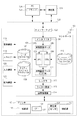
図1は本実施例におけるシステムの構成図である。シアン、マゼンタ、イエロー、ブラック(以下、C、M、Y、K)の各トナーを用いるカラー画像処理装置のMFP(Multi Function Printer)101はネットワーク123を介して他のネットワーク対応機器と接続されている。またPC124はネットワーク123を介してMFP101と接続されている。PC124内のプリンタドライバ125はMFP101へ印刷データを送信する。
Hereinafter, embodiments for carrying out the present invention will be described with reference to the drawings.
FIG. 1 is a configuration diagram of a system in this embodiment. An MFP (Multi Function Printer) 101 of a color image processing apparatus that uses cyan, magenta, yellow, and black (hereinafter, C, M, Y, and K) toners is connected to other network compatible devices via a
MFP101について詳細に説明する。ネットワークI/F122は印刷データ等の受信を行う。コントローラ102はCPU103やレンダラ112、画像処理部114で構成される。CPU103のインタプリタ104は受信した印刷データのPDL(ページ記述言語)部分を解釈し、中間言語データ105を生成する。
The
そしてCMS106ではソースプロファイル107及びデスティネーションプロファイル108を用いて色変換を行い、中間言語データ(CMS後)111を生成する。ここでCMSとはColor Management Systemの略であり、後述するプロファイルの情報を用いて色変換を行う。また、ソースプロファイル107はRGBやCMYK等のデバイスに依存する色空間をCIE(国際照明委員会)が定めたL*a*b*(以下、Lab)やXYZ等のデバイス非依存の色空間に変換するためのプロファイルである。XYZはLabと同様にデバイス非依存の色空間であり、3種類の刺激値で色を表現する。また、デスティネーションプロファイル108はデバイス非依存色空間をデバイス(プリンタ115)に依存したCMYK色空間に変換するためのプロファイルである。
The
一方、CMS109ではデバイスリンクプロファイル110を用いて色変換を行い、中間言語データ(CMS後)111を生成する。ここでデバイスリンクプロファイル110はRGBやCMYK等のデバイス依存色空間をデバイス(プリンタ115)に依存したCMYK色空間に直接変換するためのプロファイルである。CMS106、CMS109のうち、どちらのCMSが選ばれるかはプリンタドライバ125における設定に依存する。
On the other hand, the
本実施例ではプロファイル(107、108及び110)の種類によってCMS(106及び109)を分けているが、1つのCMSで複数種類のプロファイルを扱ってもよい。また、プロファイルの種類は本実施例で挙げた例に限らずプリンタ115のデバイス依存CMYK色空間を用いるのであればどのような種類のプロファイルでもよい。
In this embodiment, the CMSs (106 and 109) are divided according to the types of profiles (107, 108 and 110), but a plurality of types of profiles may be handled by one CMS. The type of profile is not limited to the example given in the present embodiment, and any type of profile may be used as long as the device-dependent CMYK color space of the
レンダラ112は生成した中間言語データ(CMS後)111からラスター画像113を生成する。画像処理部114はラスター画像113やスキャナ119で読み込んだ画像に対して画像処理を行う。画像処理部114について詳細は後述する。
The
コントローラ102と接続されたプリンタ115はC、M、Y、K等の有色トナーを用いて紙上に出力データを用いてカラー画像を形成するプリンタである。プリンタ115は給紙を行う給紙部116と画像形成された紙を排紙する排紙部117、測定部126を持つ。
A
測定部126は分光反射率、LabやXYZ等のデバイスに依存しない色空間の値を取得できる測色部のセンサ127を持ち、プリンタ115を制御するCPU129によって制御される。測定部126はプリンタ115で用紙等の記録媒体上にプリント出力されたパッチ画像を測定する。
The
この測定部126は、用紙上に定着された後のパッチ画像を測定するセンサ(以下、定着後センサとする)でもよく、プリンタ115内部の用紙を定着してから排紙をするまでの用紙搬送路上後に設置され、出力されたチャート画像を読み込む。よって、このプリンタに内蔵されたセンサ127を用いることで、測定時にユーザの動作を介さずにチャート画像の読み込みができる。
The measuring
また、このパッチ画像は、単一濃度で所定の面積を有する測定用の画像である。このパッチ画像を、色を変えて複数個生成し、生成されたパッチ画像を記録媒体上に印刷したものをパターン画像と呼ぶ。このパターン画像を測定部126が有するセンサ127で読み取り、読み取った数値情報をコントローラ102へ送信する。コントローラ102はその数値情報を用いて演算を行い、この演算の結果を単色キャリブレーションや混色キャリブレーションを実行する際に利用する。
The patch image is a measurement image having a predetermined area with a single density. A plurality of patch images having different colors are generated, and the generated patch image printed on a recording medium is called a pattern image. The pattern image is read by the
表示装置118はユーザへの指示やMFP101の状態を表示するUI(ユーザーインターフェース)である。後述する単色キャリブレーションや混色キャリブレーションを実行する際に利用する。
A
スキャナ119はオートドキュメントフィーダーを含むスキャナである。スキャナ119は束状のあるいは一枚の原稿画像を図示しない光源で照射し、原稿反射像をレンズでCCD(Charge Coupled Device)センサ等の固体撮像素子上に結像する。そして、固体撮像素子からラスター状の画像読み取り信号を画像データとして得る。
The
入力装置120はユーザからの入力を受け付けるためのインタフェースである。一部の入力装置をタッチパネルとし、表示装置118と一体化してもよい。
The
記憶装置121はコントローラ102で処理されたデータやコントローラ102が受け取ったデータ等を保存する。
The
測定器128はネットワーク上またはPC124に接続された外部の測定用デバイスであり、測定部126と同様に分光反射率、LabやXYZ等のデバイスに依存しない色空間の値を取得できる。
The measuring
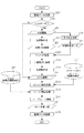
次に画像処理部114の流れについて図2を用いて説明する。図2はラスター画像113やスキャナ119で読み込んだ画像に対して行う画像処理の流れを示している。図2の処理の流れは画像処理部114内にある不図示のASIC(Application Specific Integrated Circuit)が実行することにより実現される。
Next, the flow of the image processing unit 114 will be described with reference to FIG. FIG. 2 shows the flow of image processing performed on the raster image 113 and the image read by the
ステップS201にて画像データを受信する。そしてステップS202にて受け取ったデータがスキャナ119から受信したスキャンデータかプリンタドライバ125から送られたラスター画像113かを判別する。
In step S201, image data is received. In step S202, it is determined whether the received data is the scan data received from the
スキャンデータではない場合はレンダラ112によってビットマップ展開されたラスター画像113であり、CMSによってプリンタデバイスに依存するCMYKに変換されたCMYK画像211となる。
If it is not scan data, it is a raster image 113 that has been bitmap-developed by the
スキャンデータの場合はRGB画像203であるため、ステップS204にて色変換処理を行い、共通RGB画像205を生成する。ここで共通RGB画像205とはデバイスに依存しないRGB色空間で定義されており、演算によってLab等のデバイス非依存色空間に変換することが可能である。
Since the scan data is an
一方、ステップS206にて文字判定処理を行い、文字判定データ207を生成する。ここでは画像のエッジ等を検出して文字判定データ207を生成する。
On the other hand, character determination processing is performed in step S206 to generate
次にステップS208にて共通RGB画像205に対して文字判定データ207を用いてフィルタ処理を行う。ここでは文字判定データ207を用いて文字部とそれ以外で異なるフィルタ処理を行う。
In step S208, the
次にステップS209にて下地飛ばし処理、ステップS210で色変換処理を行って下地を除去したCMYK画像211を生成する。
Next, a background removal process is performed in step S209, and a color conversion process is performed in step S210 to generate a
次にステップS212にて4D−LUT217を用いた混色の補正処理を行う。4D−LUTとはあるC、M、Y、K各トナーを出力する際の信号値の組み合わせを異なるC、M、Y、Kの信号値の組み合わせに変換する4次元のLUT(Look Up Table)である。この4D−LUT217は後述する「混色キャリブレーション」により生成される。4D−LUTを用いることで複数のトナーを使用した色である「混色」を補正することが可能になる。
In step S212, color mixture correction processing using the 4D-
そしてステップS212にて混色の補正をした後、画像処理部114はステップS213にて1D−LUT218を用いてC、M、Y、Kの各単色の階調特性を補正する。1D−LUT とはC、M、Y、Kのそれぞれの色(単色)を補正する1次元のLUT(Look Up Table)のことである。この、1D−LUTは、後述する「単色キャリブレーション」により生成される。
Then, after correcting the color mixture in step S212, the image processing unit 114 corrects the gradation characteristics of each single color of C, M, Y, and K using the 1D-
最後にステップS214にて画像処理部114はスクリーン処理や誤差拡散処理のようなハーフトーン処理を行ってCMYK画像(2値)215を作成し、ステップS216にて画像データをプリンタ115へ送信する。
Finally, in step S214, the image processing unit 114 performs halftone processing such as screen processing and error diffusion processing to create a CMYK image (binary) 215, and transmits the image data to the
プリンタ115から出力される単色の階調特性を補正する「単色キャリブレーション」について図3を用いて説明する。単色キャリブレーションを実行することで、最大濃度特性及び階調特性などの単色の色再現特性が補正される。プリンタ115で用いられるC,M,Y,Kトナー其々に対応する色の再現特性は、キャリブレーション実行時に一緒に補正される。すなわち、C,M,Y,Kの各色に応じて図3の処理が一度に実行される。
“Monocolor calibration” for correcting the monochromatic gradation characteristics output from the
図3は単色の階調特性を補正する1D−LUT218を作成する処理の流れを示している。図3の処理の流れはCPU103が実行することによって実現され、作成された1D−LUT218は記憶装置121に保存される。また表示装置118によってユーザへの指示をUIに表示し、入力装置120からユーザの指示を受け付ける。
FIG. 3 shows the flow of processing for creating a 1D-
ステップS301にて記憶装置121に格納してあるチャートデータ(A)302を取得する。チャートデータ(A)302は単色各色の最大濃度を補正するためのものであり、C、M、Y、Kの「単色」の最大濃度データが得られる信号値(例えば255)で構成される。
In step S301, chart data (A) 302 stored in the
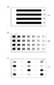
次にステップS303にてチャートデータ(A)302に対して画像処理部114にて画像処理を実行してプリンタ115からパターン画像であるチャート画像(A)304をプリント出力する。例を図5に示す。図5(a)の501はチャートデータ(A)302をプリント出力した際の例を示しており、パッチ画像502、503、504、505はそれぞれC、M、Y、K各色の最大濃度でプリント出力される。このようにパターン画像であるチャート画像(A)304は、パッチ画像を複数含む。ここで画像処理部114はステップS214にてハーフトーン処理のみ行い、ステップS213の1D−LUT補正処理やステップS212の4D−LUT補正処理は行わない。
In step S303, the image processing unit 114 executes image processing on the chart data (A) 302, and the
次にステップS305にてスキャナ119や測定部126内のセンサ127を用いてチャート画像(A)304のプリント出力物の濃度測定を行い、測定値(A)306を得る。
ユーザの動作を介さずに、キャリブレーションを実行する場合には、センサ127を用いてチャート画像(A)304の測定を行う。測定値(A)306はC、M、Y、K各色の濃度値となる。次にステップS307にて測定値(A)306と予め設定された最大濃度値の目標値(A)308を用いて各色の測定値(A)306の最大濃度の補正を実行する。ここでは最大濃度が目標値308(A)に近づくようにプリンタ115のデバイス設定値、例えば、レーザ出力や現像バイアス等を調整する。
In step S305, the density of the printed output of the chart image (A) 304 is measured using the
When the calibration is executed without the user's operation, the chart image (A) 304 is measured using the
次に、ステップS309にて記憶装置121に格納されたチャートデータ(B)310を取得する。チャートデータ(B)310はC、M、Y、Kの「単色」の階調データの信号値で構成される。このチャートデータ(B)310を用いて記録媒体にプリント出力されたパッチ画像を有するパターン画像であるチャート画像(B)312の例を図5に示す。図5(b)の506はチャートデータ(B)310を用いて記録媒体にプリント出力されたパッチ画像を有するチャート画像(B)312のプリント出力物の一例を示している。図5(b)に示されるパッチ画像507、508、509、510及び右に続く階調データは、C、M、Y、K各色の階調データで構成される。このようにパターン画像であるチャート画像(B)312は、パッチ画像を複数含む。
Next, chart data (B) 310 stored in the
次にステップS311にてチャートデータ(B)310に対して画像処理部114にて画像処理を実行してプリンタ115からチャート画像(B)312をプリント出力する。ここで画像処理部114、ステップS214にてハーフトーン処理のみ行い、ステップS213の1D−LUT補正処理やステップS212の4D−LUT補正処理は行わない。また、プリンタ115はステップS307により最大濃度補正を行っているため、最大濃度が目標値(A)308と同等の値を出せる状態となる。
In step S <b> 311, the image processing unit 114 executes image processing on the chart data (B) 310 and prints out the chart image (B) 312 from the
次にステップS313にてスキャナ119やセンサ127を用いて測定を行い、測定値(B)314を得る。
ユーザの動作を介さずに、キャリブレーションを実行する場合には、センサ127を用いてチャート画像(B)314の測定を行う。
測定値(B)314はC、M、Y、K各色の階調から得られる濃度値となる。次にステップS315にて測定値(B)314と予め設定された目標値(B)316を用いて単色の階調を補正する1D−LUT218を作成する。
Next, in step S313, measurement is performed using the
When the calibration is executed without the user's operation, the chart image (B) 314 is measured using the
The measured value (B) 314 is a density value obtained from the gradation of each color of C, M, Y, and K. Next, in step S315, a 1D-
次に、プリンタ115から出力される混色の特性を補正する「混色キャリブレーション」について図4を用いて説明する。混色キャリブレーションを実行することで、複数色のトナーの組み合わせ(重ね合わせなど)で表現される混色の再現特性が補正される。以下の処理の流れはコントローラ102内のCPU103が実行することにより実現される。この取得された4D−LUT217は記憶装置121に保存される。また表示装置118によってユーザへの指示をUIに表示し、入力装置120からユーザの指示を受け付ける。
Next, “mixed color calibration” for correcting the mixed color characteristics output from the
混色キャリブレーションは、単色キャリブレーション実施後にプリンタ115から出力される混色を補正する。そのため、単色キャリブレーションを行った直後に混色キャリブレーションを行うことが望ましい。
The color mixture calibration corrects the color mixture output from the
ステップS401にて記憶装置121に格納してある「混色」で構成されたチャートデータ(C)402の情報を取得する。チャートデータ(C)402は混色を補正するためのデータであり、C、M、Y、Kの組み合わせである「混色」の信号値で構成される。このチャートデータ(C)402を用いて記録媒体にプリント出力された複数のパッチ画像を有するパターン画像であるチャート画像(C)404の一例を図5に示す。図5(c)の511はチャートデータ(C)402をプリント出力した際の例を示しており、パッチ画像512及び511上に印字された全てのパッチ画像はC、M、Y、Kを組み合わせた混色で構成されている。このようにパターン画像であるチャート画像(C)404は、パッチ画像を複数含む。
In step S401, information of the chart data (C) 402 configured by “color mixing” stored in the
次にステップS403では画像処理部114にてチャートデータ(C)402に対して画像処理を実行してプリンタ115にてチャート画像(C)404をプリント出力する。混色キャリブレーションは単色キャリブレーション実施後のデバイスの混色特性を補正するため、画像処理部114での画像処理の実行には単色キャリブレーション実行時に作成された1D−LUT218を用いる。
In step S403, the image processing unit 114 performs image processing on the chart data (C) 402, and the
次にステップS405にてスキャナ119や測定部126内のセンサ127を用いてチャート画像(C)404のプリント出力物の混色の測定を行い、測定値(C)406を取得する。
ユーザの動作を介さずに、キャリブレーションを実行する場合には、センサ127を用いてチャート画像(C)406の測定を行う。
測定値(C)406は単色キャリブレーション実施後のプリンタ115の混色特性を示す。また、測定値(C)406はデバイスに依存しない色空間での値であり、本実施例ではLabとする。スキャナ119を用いた場合は図示しない3D−LUT等を用いてRGB値をLab値に変換する。
Next, in step S405, the mixed color of the printed output of the chart image (C) 404 is measured using the
When the calibration is executed without the user's operation, the chart image (C) 406 is measured using the
A measured value (C) 406 indicates the color mixing characteristics of the
次にステップS407にて記憶装置121に格納してあるLab→CMYの3D−LUT409を取得し、測定値406(C)と予め設定された目標値(C)408との差分を反映させてLab→CMYの3D−LUT(補正後)410を作成する。ここでLab→CMYの3D−LUTとは、入力されたLab値に対応するCMY値を出力する3次元のLUTのことである。
Next, in step S407, the Lab →
具体的な作成方法を以下に示す。Lab→CMYの3D−LUT409の入力側のLab値に対して測定値406(C)と予め設定された目標値(C)408との差分を加え、差分が反映されたLab値に対してLab→CMYの3D−LUT409を用いて補間演算を実行する。この結果、Lab→CMYの3D−LUT(補正後)410を作成する。
The specific creation method is shown below. The difference between the measured value 406 (C) and the preset target value (C) 408 is added to the Lab value on the input side of the Lab →
次にステップS411にて記憶装置121に格納してあるCMY→ Labの3D−LUT412を取得して、Lab→CMYの3D−LUT(補正後)410を用いて演算を行う。これにより、CMYK→CMYKの4D−LUT217を作成する。ここでCMY→Labの3D−LUTとは、入力されたCMY値に対応するLab値を出力する3次元のLUTのことである。
In step S 411, the CMY →
CMYK→CMYKの4D−LUT217の具体的な作成方法を以下に示す。CMY→ Labの3D−LUT412とLab→CMYの3D−LUT(補正後)410からCMY→CMYの3D−LUTを作成する。次にKの入力値と出力値が同一となるようにCMYK→CMYKの4D−LUT217を作成する。ここでCMY→CMYの3D−LUTとは、入力されたCMY値に対応する補正後のCMY値を出力する3次元のLUTのことである。
A specific method for creating the CMYK →
単色キャリブレーションおよび混色キャリブレーションを選択的に実行する際のポータル画面の例を図13に示す。 FIG. 13 shows an example of a portal screen when selectively executing single color calibration and mixed color calibration.
本画面では各種キャリブレーションなど、よく使用される機能を起動するためのボタンが集約されて表示されており、少なくとも単色キャリブレーションと混色キャリブレーションを連続で実行させるための連続キャリブレーションボタン1304を含んでいる。また、単色キャリブレーションを実行させるための単色キャリブレーションボタン1302や混色キャリブレーションを実行させるための混色キャリブレーションボタン1303やその他のボタンを含んでいてもよい。
On this screen, buttons for starting frequently used functions such as various calibrations are displayed in an aggregated manner, and includes at least a
単色キャリブレーションボタン1302が押下された場合は単色キャリブレーション実行指示画面701に遷移する。
When the
混色キャリブレーションボタン1303が押下された場合は混色キャリブレーション実行指示画面1001に遷移する。
When the mixed
連続キャリブレーションボタン1304が選択されると、図16の給紙段選択のための画面が表示され、選択された紙種に属する用紙により、連続キャリブレーションが実行される。図16については後述する。
When the
具体的には、単色キャリブレーション終了後に、混色キャリブレーション用のチャート画像(C)404をプリント出力することで、混色キャリブレーションを開始する。または、ユーザに混色キャリブレーションを開始するためのボタンをUI画面に表示し、そのボタンがユーザにより押下されてから、混色キャリブレーションが開始されても良い。 Specifically, after completion of the single color calibration, the mixed color calibration is started by printing out the chart image (C) 404 for the mixed color calibration. Alternatively, the user may display a button for starting the color mixture calibration on the UI screen, and the color mixture calibration may be started after the user presses the button.
一方、ボタン1302が選択されると、単色キャリブレーションのみ実行される。同様に、ボタン1303が選択されると、混色キャリブレーションのみ実行される。
On the other hand, when the
単色キャリブレーションと混色キャリブレーションでボタンを分けている理由について説明する。混色キャリブレーション実行時に使用するチャート画像(C)404をプリント出力する時、単色キャリブレーションで作成した1D−LUT218を使用する。よって、単色キャリブレーションの直後、単色の再現特性が補正された直後に混色キャリブレーションを行い、混色の再現特性を補正することが望ましい。しかし、2種類のキャリブレーションを両方実行すると、ユーザがキャリブレーションのために費やす処理時間が多くかかってしまう。
The reason why the buttons are divided for single color calibration and mixed color calibration will be described. When the chart image (C) 404 used for executing the color mixture calibration is printed out, the 1D-
よって、処理時間を短縮するためにユーザの使用環境に応じて単色キャリブレーションと混色キャリブレーションのいずれかを実行させる。すると、両キャリブレーションの実行頻度が異なる状況が発生する。例えば単色プリントを行う機会が多いユーザは、混色キャリブレーションを実行する頻度が低くなる。また、写真のような混色のカラープリントを行う機会が多いユーザは、混色キャリブレーションを実行する頻度が高くなる。 Therefore, in order to shorten the processing time, either single color calibration or mixed color calibration is executed according to the user's usage environment. Then, the situation where the execution frequency of both calibrations differs occurs. For example, a user who frequently performs monochrome printing has a low frequency of executing the color mixture calibration. In addition, a user who frequently performs mixed color printing such as a photograph has a higher frequency of executing mixed color calibration.
また、この色補正メニューの選択が可能なタイミングを制御してもよい。 Further, the timing at which this color correction menu can be selected may be controlled.
通常、画像処理装置は、電源を夜間切り、朝入れるケースが多い。よって、MFP101のメイン電源スィッチがオンになり、電源が投入された時には、ボタン1304しか選択できないようにする。または、予め定められた時間内に、両方のキャリブレーションが実行されない場合には、ボタン1304しか選択できないようにしてもよい。または、予め定められた枚数の用紙を用いて印刷が実行されるまでに、両方のキャリブレーションが実行されない場合には、ボタン1304しか選択できないようにしてもよい。
Usually, image processing apparatuses are often turned off at night and turned on in the morning. Accordingly, when the main power switch of the
または、予め定められた時間が経過したり、予め定められた枚数の用紙を用いて印刷が実行されたり、電源が投入された場合に、自動的に単色キャリブレーションと混色キャリブレーションが順次実行されてもよい。 Alternatively, when a predetermined time has elapsed, printing is performed using a predetermined number of sheets, or power is turned on, the single color calibration and the mixed color calibration are automatically performed sequentially. May be.
このように、所定のタイミングではユーザがキャリブレーションを実行する際に、ボタン1304のみ選択できるようにして、予め定められた一定時間ごとに単色キャリブレーション実行直後に混色キャリブレーションを実行するように促す。
In this way, when the user performs calibration at a predetermined timing, only the
よって、上記のように単色キャリブレーション実行後に混色キャリブレーションを実行して両方のキャリブレーションを実行するか、単色キャリブレーション、混色キャリブレーションのいずれかを実行するかを選択することができる。これにより、ユーザの使用に適したキャリブレーションを実行することが可能になる。 Therefore, as described above, it is possible to select whether to execute both color calibrations by executing the color mixture calibration after executing the single color calibration, or to execute either the single color calibration or the color mixing calibration. This makes it possible to execute calibration suitable for the user's use.
また、一定時間ごとに両方のキャリブレーションを実行することのみ選択できるように制御することで、いずれか一方のキャリブレーションのみ実行されることによりキャリブレーションによる再現特性の補正精度の低下を抑制することが可能になる。本実施例は、図13の1304ボタンが押下され、単色キャリブレーション実行後に混色キャリブレーションが自動で連続して実行される「連続キャリブレーション」の実行が指示された時に実施される。 In addition, by controlling so that only both calibrations can be selected at regular time intervals, only one of the calibrations is executed, thereby suppressing a reduction in the correction accuracy of reproduction characteristics due to calibration. Is possible. This embodiment is implemented when the button “1304” in FIG. 13 is pressed and execution of “continuous calibration” in which mixed color calibration is automatically performed continuously after execution of single color calibration is instructed.
なお、MFP101の記憶装置121には複数の紙種にそれぞれ対応した目標値(A)と目標値(B)が対になった情報と、その対になった目標値を登録した日時の情報を示すタイムスタンプ情報を記憶しておくことができる。また、MFP101の記憶装置121には複数の紙種それぞれ対応した目標値(C)と、この紙種に対応した目標値(C)を登録した日時の情報を示すタイムスタンプ情報を記憶しておくことができる。
It should be noted that the
また、1D−LUT218と4D−LUT217は作成したときのタイムスタンプ情報とLUT作成に用いた用紙に関する情報である用紙情報をともに記憶装置121に記憶しておくことができる。用紙情報は少なくとも用紙の種類(紙種)が含まれる。
The 1D-
図7は単色キャリブレーション実行指示画面701の例を示している。
FIG. 7 shows an example of a monochromatic calibration
単色キャリブレーション実行指示画面701は少なくとも補正用紙登録ボタン702、補正用紙選択ボタン703、実行開始ボタン704を有している。
The monochrome calibration
補正用紙登録ボタン702が押下されると、図8の画面へ遷移する。また、補正用紙選択ボタン703が押下されると、図9の画面へ遷移する。
When the correction
実行開始ボタン704の押下により実行開始命令を受け付けた場合はその時選択されている用紙に対応した最大値の目標値(A)と階調性の目標値(B)を用いて図3で説明した単色キャリブレーションを実行する。
When the execution start command is received by pressing the
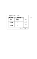
図8は補正用紙登録ボタン702が押下された時の単色キャリブレーション用紙登録画面801を示している。図8では登録できる用紙が補正用紙1 802、補正用紙2 803、補正用紙3 804の三種類である場合の例を示しているが、これを限定しているものではない。登録できる用紙は一種類以上であれば何種類あってもよい。本画面において補正用紙1、補正用紙2、補正用紙3の紙種と目標値(A)と目標値(B)を対にして記憶させることができる。すなわち、補正用紙1として普通紙Aが登録されると、この普通紙Aに対応した目標値(A)と目標値(B)が紙種(普通紙A)を示す情報と紐づけられて記憶される。同様に補正用紙2として厚紙が登録されると、この厚紙に対応した目標値(A)と目標値(B)が紙種(厚紙)を示す情報と紐づけられて記憶される。
FIG. 8 shows a monochromatic calibration
このように、紙種と、紙種に対応する目標値(または目標値を生成するためのパラメータ)を紐づけて記憶する処理を登録処理とする。 In this way, the process of storing the paper type and the target value (or the parameter for generating the target value) corresponding to the paper type in association with each other is referred to as a registration process.
登録完了ボタン805を押下することで図7の単色キャリブレーション実行指示画面701に遷移する。
When the
図9は補正用紙選択ボタン703が押下された時の単色キャリブレーション用紙選択画面901を示している。図9では単色キャリブレーション用紙登録画面801で登録された補正用紙の用紙情報(紙種)がそれぞれ902、903、904に表示されており、これらから実行される単色キャリブレーションに使用する紙種を選択することができる。選択完了ボタン905を押下することで図7の単色キャリブレーション実行指示画面701に遷移する。
FIG. 9 shows a monochromatic calibration
図10は混色キャリブレーション実行指示画面1001の例を示している。
FIG. 10 shows an example of the mixed color calibration
混色キャリブレーション実行指示画面1001は少なくとも補正用紙登録ボタン1002、補正用紙選択ボタン1003、実行開始ボタン1004を有している。
The mixed color calibration
実行開始ボタン1004の押下により実行開始命令を受け付けた場合はその時選択されている用紙に対応した目標値(C)を用いて図4で説明した混色キャリブレーションを実行する。
When an execution start command is received by pressing the
補正用紙登録ボタン1002が押下されると、図11の画面へ遷移する。また、補正用紙選択ボタン1003が押下されると、図12の画面へ遷移する。
When the correction
図11は補正用紙登録ボタン1002が押下された時の混色キャリブレーション用紙登録画面1101を示している。図11では登録できる用紙が補正用紙1 1102、補正用紙2 1103、補正用紙3 1104の三種類である場合の例を示しているが、これを限定しているものではない。登録できる用紙は一種類以上であれば何種類あってもよい。本画面において補正用紙1、補正用紙2、補正用紙3の紙種類と目標値(C)をそれぞれ対にして記憶させることができる。すなわち、補正用紙1として普通紙Aが登録されると、この普通紙Aに対応した目標値(C)が紙種(普通紙A)を示す情報と紐づけられて記憶される。
FIG. 11 shows a mixed color calibration
登録完了ボタン805を押下することで図10の混色キャリブレーション実行指示画面1001に遷移する。
When the
図12は補正用紙選択ボタン1003が押下された時の混色キャリブレーション用紙選択画面1201を示している。図12では混色キャリブレーション用紙登録画面1101で登録された補正用紙の用紙情報(紙種)がそれぞれ1202、1203、1204に表示されており、これらから実行される混色キャリブレーションに使用する紙種を選択することができる。選択完了ボタン1205を押下することで図10の混色キャリブレーション実行指示画面1001に遷移する。
FIG. 12 shows a mixed color calibration
本実施例では画像形成装置としてMFP(Multi Function Printer)を用いし、連続キャリブレーションの実施が指示された場合、連続キャリブレーションに使用する用紙を選択する動作について説明する。 In this embodiment, an operation of selecting a sheet to be used for continuous calibration when an MFP (Multi Function Printer) is used as an image forming apparatus and execution of continuous calibration is instructed will be described.
図6はMFP101の給紙部116の例を示すものである。この例においてMFP101には用紙を格納するトレイ状の第一、第二、第三、第四、第五の給紙段601、602、603、604、605が具備されている。それぞれの給紙段には異なる種類の用紙を格納することが可能である。
FIG. 6 shows an example of the
ユーザが給紙段に格納した用紙情報を入力装置120から入力することによって、CPU103は記憶装置121に前記第一から第五の給紙段と用紙情報を対応づけて給紙段の情報を格納する。なお、本実施例では第一から第五の給紙段を例に挙げているがこの給紙段はトレイ状や手差しなどの形態を限定するものではない。また、給紙段はMFP101に1つ以上あればよいものである。
When the user inputs the paper information stored in the paper feed stage from the
図14は本実施例の動作フローを示すフローチャートである。 FIG. 14 is a flowchart showing the operation flow of this embodiment.
本フローチャートの各ステップは不図示の制御プログラムは記憶装置121に格納されており、不図示のRAMにロードされて、CPU103によって実行されるものである。
In each step of this flowchart, a control program (not shown) is stored in the
図14に示されている処理は、図8および図11のそれぞれで、登録が実行された後に開始される処理である。 The process shown in FIG. 14 is a process that is started after registration is executed in each of FIGS. 8 and 11.
各種動作ポータル画面1301にて連続キャリブレーションボタン1304が押下されると、CPU103は記憶装置121から単色キャリブレーション実行に用いられるよう登録されている登録用紙情報を読み出す(ステップS1401)。
When the
続いてCPU103は記憶装置121から混色キャリブレーション実行に用いられるよう登録されている登録用紙情報を読み出す(ステップS1402)。
Subsequently, the
CPU103はステップS1401にて読み出した単色キャリブレーション用の登録用紙と、ステップS1402にて読み出した混色キャリブレーション用の登録用紙を比較する。そして、各キャリブレーション用の用紙として登録した紙種の中で、各キャリブレーションに共通して登録された紙種を抽出し、確定する(ステップS1403)。図15は単色キャリブレーション実行に用いるために登録された紙種と混色キャリブレーション実行に用いるために登録された紙種の例を示す図である。ここで単色キャリブレーションでは普通紙A、厚紙、コート紙が登録さているとする。また、混色キャリブレーションでは普通紙A、普通紙B、コート紙が登録されているとする。このような例の場合、普通紙Aとコート紙が共通の紙種として抽出し、確定される。以下、この抽出された紙種を「共通の紙種」と呼ぶ。
The
CPU103は記憶装置121から給紙段情報を読み出し、ステップS1403で確定した共通の紙種と照合する(ステップS1404)。
The
ステップS1404で照合した結果、いずれの給紙段に共通の紙種に属する用紙が格納されているか否かを判定する(ステップS1405)。 As a result of the collation in step S1404, it is determined whether or not a sheet belonging to a common sheet type is stored in any sheet feeding stage (step S1405).
ステップS1405にていずれかの給紙段に、ステップS1405にて確定された共通の紙種に属する用紙が格納されている場合、表示装置118に共通の紙種に属する用紙が格納されている給紙段を、例えば図16の様に表示する(ステップS1406)。
If paper belonging to the common paper type determined in step S1405 is stored in any paper feed stage in step S1405, the paper belonging to the common paper type is stored in the
図16 は連続キャリブレーションボタン1304が押下された後に表示される給紙段選択画面1601の一例を示している。この画面では第一の給紙段から第五の給紙段に格納されている用紙情報と共にステップS1405で判定された共通の紙種に属する用紙が格納されている給紙段が表示される。いずれか一方のキャリブレーション実行のために用いる用紙としてしか登録されていない紙種が格納されている給紙段はグレーアウトされている。これによりグレーアウトされている給紙段に格納されている用紙は連続キャリブレーション実行時には使用できないことを示している。即ち本実施例では給紙段1と給紙段3の普通紙Aとコート紙のみが連続キャリブレーション実行時に使用できることになる。なお、本実施例では連続キャリブレーション実行時に使用できない用紙が格納されている給紙段をグレーアウトしたが、これに限ることは無い。
FIG. 16 shows an example of a paper feed
例えば、図17のように連続キャリブレーション実行時に使用できる用紙が格納されている給紙段のみが表示されていても良いし、連続キャリブレーション実行時に使用できる用紙が格納されている給紙段とそうでない給紙段が区別して表示されていればよい。連続キャリブレーション実行時に使用する用紙、即ちこの場合給紙段1もしくは給紙段3を選択した後に連続キャリブレーション実行ボタン1602を押下したか否かを判断する(ステップS1407)。連続キャリブレーション実行ボタン1602が押下されるまで待機し、連続キャリブレーション実行ボタン1602が押下された場合は連続キャリブレーションを実行する(ステップS1407)。
For example, as shown in FIG. 17, only a paper feed stage that stores paper that can be used during continuous calibration may be displayed, or a paper feed stage that stores paper that can be used during continuous calibration. It is only necessary that the other paper feed trays are displayed separately. It is determined whether or not the continuous
ステップS1405にていずれの給紙段にも共通の紙種に属する用紙が格納されていない場合は図16の連続キャリブレーション実行ボタン1602を無効にする(ステップS1408)。そして五つある給紙段のいずれかに対して用紙の入れ替えがあるか否かを監視する(ステップS1409)。
If no paper belonging to a common paper type is stored in any paper feed stage in step S1405, the continuous
なお、ステップS1409では図16ないし図17の給紙段選択画面上に、いずれかの給紙段にステップS1403にて確定された紙種のうち、いずれかの紙種に属する用紙を格納することをユーザに通知するための表示をしても良い。ステップS1409で給紙段に対して用紙の入れ替えがあった場合、入れ替えられた用紙が共通の紙種に属する用紙であるか否かを判断する(ステップS1410)。用紙の入れ替えに関しては例えば給紙段の開閉を検知する図示しない給紙段開閉センサを用いて検出する。CPU103は給紙段開閉センサの信号を監視し、給紙段開閉センサが給紙段の開放の信号を出した後に閉鎖の信号を出した場合には用紙の入れ替えが発生したと仮定することができる。その後にユーザは各給紙段に格納した用紙情報を入力装置120から入力するが、その内容が直前に入力されていた用紙情報と比較して、用紙情報に変更があった場合に、給紙段に対して用紙の入れ替えが発生したことを確定できる。この用紙情報を基に、入れ替えられた用紙が共通の紙種に属する用紙であるか否かを判断することができる。
In step S1409, sheets belonging to any one of the paper types determined in step S1403 are stored in any paper feed stage on the paper feed stage selection screen of FIGS. May be displayed to notify the user. If the paper is changed for the paper feed stage in step S1409, it is determined whether or not the changed paper belongs to a common paper type (step S1410). For example, a paper feed stage opening / closing sensor (not shown) that detects the opening / closing of the paper feed stage is detected. The
ステップS1410で共通の紙種に属する用紙であると判断した場合はステップS1406に進む。また、ステップS1410で共通の紙種に属する用紙ではないと判断した場合はステップS1409に戻り、用紙の入れ替えを待機する。 If it is determined in step S1410 that the paper belongs to the common paper type, the process advances to step S1406. If it is determined in step S1410 that the sheets do not belong to the common sheet type, the process returns to step S1409 to wait for replacement of sheets.
なお、表示装置118には常に図示しないキャンセルボタンが表示されており、これが押下されると、前述した全ての動作を強制的に中止し、装置の初期画面に相当する画面に遷移する。
Note that a cancel button (not shown) is always displayed on the
以上説明したように本実施例により、補正対象が異なるキャリブレーションを連続して実行する際に、キャリブレーションに使用する用紙の紙種の選択もしくは選択した紙種に属する用紙が格納される給紙段の選択を一度の処理で行うことができる。これにより、連続キャリブレーション実行時の給紙段選択の操作を簡単化することが可能となる。さらに補正対象の異なる複数のキャリブレーションを連続して実行する際に少ない処理で実行命令を受け付けられる。よって、ユーザの手間を減らし、キャリブレーション実行指示時のユーザの手離れを早めることが可能となる。 As described above, according to the present embodiment, when calibrations having different correction targets are successively executed, the paper type used for calibration is selected or the paper belonging to the selected paper type is stored. The stage can be selected in a single process. As a result, it is possible to simplify the operation of selecting a paper feed stage when performing continuous calibration. Furthermore, when a plurality of calibrations with different correction targets are successively executed, an execution command can be received with a small amount of processing. Therefore, it is possible to reduce the user's time and speed up the user's time to release the calibration execution instruction.
また、単色キャリブレーションや混色キャリブレーションといった補正対象の異なる複数のキャリブレーションを連続して実行する際、単色キャリブレーション実行時に用いられる紙種と混色キャリブレーション実行時に用いられる紙種を統一することが容易になる。よって、混色キャリブレーション用の目標値を複数登録する必要がなくなる。 In addition, when multiple calibrations with different correction targets, such as single color calibration and mixed color calibration, are executed in succession, the paper type used when executing the single color calibration and the paper type used when executing the mixed color calibration may be unified. It becomes easy. This eliminates the need to register a plurality of target values for color mixture calibration.
本実施例では各種動作ポータル画面1301にて連続キャリブレーションボタン1304が押下された場合の連続キャリブレーション実行時に使用する用紙選択動作の別の形態について説明する。
In the present embodiment, another form of the sheet selection operation used when executing continuous calibration when the
図18は本実施例の動作フローを示すフローチャートである。 FIG. 18 is a flowchart showing the operation flow of this embodiment.
本フローチャートの各ステップは不図示の制御プログラムは記憶装置121に格納されており、不図示のRAMにロードされて、CPU103によって実行されるものである。
In each step of this flowchart, a control program (not shown) is stored in the
各種動作ポータル画面1301にて連続キャリブレーションボタン1304が押下されると、CPU103は記憶装置121から単色キャリブレーション実行時に使用される紙種として登録されている紙種を示す登録用紙情報を読み出す(ステップS1801)。
When the
続いて記憶装置121から混色キャリブレーション実行時に使用される紙種として登録されている紙種を示す登録用紙情報を読み出す(ステップS1802)。 Subsequently, registered sheet information indicating the sheet type registered as the sheet type used when executing the color mixture calibration is read from the storage device 121 (step S1802).
CPU103は記憶装置121から給紙段情報を読み出し、ステップS1403で示したように、各キャリブレーション実行時に用いる用紙として登録した紙種の中で、各キャリブレーションにて共通して登録された紙種を確定する。(ステップS1803)。
The
ステップS1803の後、MFPの給紙段状態を示す給紙段選択画面1901を図19の様に表示する(ステップS1804 )。
After step S1803, a paper feed
図19は連続キャリブレーションボタン1304が押下された後に表示される給紙段選択画面1901の例を示している。この画面では第一の給紙段から第五の給紙段に格納されている用紙情報と共にステップS1803で照合した結果、各給紙段が単色キャリブレーション実行時と混色キャリブレーション実行時に使用できる用紙か否かの情報が表示されている。図19では各キャリブレーションに使用できる場合は○、使用できない場合は×が表示されている。
FIG. 19 shows an example of a paper feed
図15に示すような登録用紙状況である場合、例えば図19のような表示をする。 When the registered sheet status is as shown in FIG. 15, for example, a display as shown in FIG.
また、×が表示されている欄には単色キャリブレーション用紙登録ボタン1902や混色キャリブレーション用紙登録ボタン1903が表示されている。
Also, a single color calibration
給紙段選択画面1901にて給紙段1もしくは給紙段3が選択された後、連続キャリブレーションボタン1304が押下された場合は、連続キャリブレーションを実行する(ステップS1805)。
If the
ステップS1805にて給紙段1や給紙段3が選択されていない場合、単色キャリブレーション用紙登録ボタン1902が押下されているか判断する(ステップS1806)。単色キャリブレーション用紙登録ボタン1902が押下されている場合は単色キャリブレーション用紙登録画面801へ遷移し、連続キャリブレーション動作を終了する(ステップS1808)。
If the
単色キャリブレーション用紙登録画面801へ遷移した場合、単色キャリブレーション実行時に用いられる用紙の登録を行い、連続キャリブレーションを実行するため、図19に示す画面に戻ってもよい。
When transitioning to the monochromatic calibration
ステップS1806にて単色キャリブレーション用紙登録ボタン1902が押下されていない場合、混色キャリブレーション用紙登録ボタン1903が押下されているかを判断する(ステップS1807)。混色キャリブレーション用紙登録ボタン1903が押下されている場合は混色キャリブレーション用紙登録画面1101へ遷移し、連続キャリブレーション動作を終了する(ステップS1809)。混色キャリブレーション用紙登録画面1101へ遷移した場合、混色キャリブレーション実行時に用いられる用紙の登録を行い、連続キャリブレーションを実行するため、図19に示す画面に戻ってもよい。
If the single color calibration
ステップS1807にて混色キャリブレーション用紙登録ボタン1903が押下されていない場合、ステップS1805に戻る。
If the mixed color calibration
以上説明したように本実施例の構成を有することで、実施例1の効果に加えて連続キャリブレーションに使用できない給紙段とどのキャリブレーションに使用できないのかという情報を明示できるようになる。よって、所望の紙種に属する用紙が連続キャリブレーション実行時に使用できない場合は、各キャリブレーション用紙登録画面に少ない操作で遷移して、所望の紙種の登録をすることができるようになる。これにより、ユーザにとって処理がわかりやすい操作画面を提供することが可能となる。 As described above, by having the configuration of the present embodiment, in addition to the effects of the first embodiment, it becomes possible to clearly indicate the paper feed stage that cannot be used for continuous calibration and the calibration that cannot be used. Therefore, when a sheet belonging to a desired paper type cannot be used at the time of performing continuous calibration, it is possible to register the desired paper type by transitioning to each calibration paper registration screen with few operations. As a result, it is possible to provide an operation screen that is easy to understand for the user.
図20はステップS1406にて表示される給紙段選択画面2001である。この画面には連続キャリブレーションに使用できる用紙が格納されている給紙段のみが表示されている。また、詳細設定ボタン2002が配置されている。
FIG. 20 shows a paper feed
詳細設定ボタン2002が押下された場合は給紙段選択画面1901に遷移する。給紙段選択画面1901に遷移したのちはステップS1804以降の動作を実施するものである。
When the
以上説明したように本実施例の構成を有することで、簡単な操作で連続キャリブレーションを実行でき、必要な場合のみ詳細な情報を提供し、少ない操作でキャリブレーション用紙登録画面に遷移できるようになる。 As described above, with the configuration of this embodiment, continuous calibration can be executed with a simple operation, detailed information can be provided only when necessary, and transition to the calibration sheet registration screen can be performed with few operations. Become.
(その他の実施例)
本発明は、以下の処理を実行することによっても実現される。即ち、上述した実施例の機能を実現するソフトウェア(プログラム)を、ネットワ又は各種記憶媒体を介してシステム或いは装置に供給し、そのシステム或いは装置のコンピュータ(またはCPUやMPU等)がプログラムを読み出して実行する処理である。
(Other examples)
The present invention is also realized by executing the following processing. That is, software (program) for realizing the functions of the above-described embodiments is supplied to a system or apparatus via a network or various storage media, and a computer (or CPU, MPU, etc.) of the system or apparatus reads the program. It is a process to be executed.
また、上記実施例について電子写真装置を例に説明をしたが、インクジェットプリンタ、サーマルプリンタ等でもよく、本発明の主旨はプリンタの種類に限定されるものではない。また、記録剤として、電子写真印刷におけるトナーを例に説明したが、印刷に用いる記録剤は、トナーに限らずインク等他の記録剤であってもよく、本発明の主旨は記録剤の種類に限定されるものではない。 Further, although the electrophotographic apparatus has been described as an example of the above embodiment, an ink jet printer, a thermal printer, or the like may be used, and the gist of the present invention is not limited to the type of printer. Further, the toner in electrophotographic printing has been described as an example of the recording agent. However, the recording agent used for printing is not limited to the toner, and may be other recording agents such as ink. The gist of the present invention is the kind of the recording agent. It is not limited to.
Claims (11)
単色キャリブレーション用の用紙として登録された紙種に前記画像形成手段により1種類のトナーを用いて形成される単色画像の色を、前記単色キャリブレーション用の用紙として登録された紙種に対応する目標値に近づけるように補正するための単色補正データを生成する単色キャリブレーションの実行と、混色キャリブレーション用の用紙として登録された紙種に前記画像形成手段により複数種類のトナーを用いて形成される混色画像の色を、前記混色キャリブレーション用の用紙として登録された紙種に対応する目標値に近づけるように補正するための混色補正データを生成する混色キャリブレーションの実行と、を制御する制御手段と、
前記単色キャリブレーションと前記混色キャリブレーションとを順に実行するように指示を受けると、前記単色キャリブレーション用の用紙として登録された紙種と前記混色キャリブレーション用の用紙として登録された紙種とに共通する紙種を選択する選択手段と、
を有し、
前記選択手段により選択された紙種に属する用紙を用いて前記制御手段により前記単色キャリブレーションと前記混色キャリブレーションとを順に実行することを特徴とする画像処理装置。 An image forming means for forming an image;
The color of the single color image formed by the image forming unit using one type of toner on the paper type registered as the single color calibration paper corresponds to the paper type registered as the single color calibration paper. Execution of single-color calibration for generating single-color correction data for correction close to the target value, and a sheet type registered as a mixed-color calibration sheet using a plurality of types of toner by the image forming unit. that the color of the mixed color image, control for controlling the, execution of the multi-color calibration to produce the color mixture correction data for correcting so as to approach a target value corresponding to the registered paper type as the paper for the color calibration Means,
When receiving an instruction to execute the single color calibration and the mixed color calibration in order, the paper type registered as the single color calibration paper and the paper type registered as the mixed color calibration paper A selection means for selecting a common paper type;
Have
The image processing apparatus characterized by sequentially performing the above color calibration and the single-color calibration by the control unit using the paper belongs to the paper type selected by the selecting means.
前記表示手段は、前記単色キャリブレーション用の用紙として登録された紙種と前記混色キャリブレーション用の用紙として登録された紙種とに共通する紙種と前記単色キャリブレーション用の用紙として登録された紙種と前記混色キャリブレーション用の用紙として登録された紙種とに共通しない紙種とを区別して表示することを特徴とする請求項1に記載の画像処理装置。 A display means causes display information about the registered paper type,
The display means has been registered as the paper for the single-color calibration the monochromatic calibration and common paper types registered as paper type as paper and paper type registered as the paper for the color calibration for The image processing apparatus according to claim 1, wherein the paper type and the paper type that is not common to the paper type registered as the color-mixing calibration paper are distinguished and displayed.
前記表示手段は、前記単色キャリブレーション用の用紙として登録された紙種と前記混色キャリブレーション用の用紙として登録された紙種とに共通する紙種でない紙種は、前記選択手段にて選択できないように表示させることを特徴とする請求項1に記載の画像処理装置。 A display means causes display information about the registered paper type,
The display means, sheet type non-sheet type which is common to the paper types that are registered as the paper for the single-color calibration sheet type and the multi-color calibration registered as paper for can not selected by said selection means The image processing apparatus according to claim 1, wherein the image processing apparatus is displayed as follows.
単色キャリブレーション用の用紙として登録された紙種に前記画像形成手段により1種類のトナーを用いて形成される単色画像の色を、前記単色キャリブレーション用の用紙として登録された紙種に対応する目標値に近づけるように補正するための単色補正データを生成する単色キャリブレーションの実行と、混色キャリブレーション用の用紙として登録された紙種に前記画像形成手段により複数種類のトナーを用いて形成される混色画像の色を、前記混色キャリブレーション用の用紙として登録された紙種に対応する目標値に近づけるように補正するための混色補正データを生成する混色キャリブレーションの実行と、を制御する制御手段と、
前記単色キャリブレーション用の用紙として登録された紙種と前記混色キャリブレーション用の用紙として登録された紙種のうち、いずれか一方のみの紙種として登録されている紙種を表示させる表示手段と、を有し、
前記表示手段により表示された紙種が、前記単色キャリブレーションと前記混色キャリブレーションとを順に実行する場合に用いられる用紙の紙種として登録されるように、前記表示手段により表示されている画面を、紙種の登録を行うために表示される画面へ遷移することを特徴とする画像処理装置。 An image forming means for forming an image;
The color of the single color image formed by the image forming unit using one type of toner on the paper type registered as the single color calibration paper corresponds to the paper type registered as the single color calibration paper. Execution of single-color calibration for generating single-color correction data for correction close to the target value, and a sheet type registered as a mixed-color calibration sheet using a plurality of types of toner by the image forming unit. that the color of the mixed color image, control for controlling the, execution of the multi-color calibration to produce the color mixture correction data for correcting so as to approach a target value corresponding to the registered paper type as the paper for the color calibration Means,
The monochromatic calibration paper type registered as paper for Configuring and among the registered paper type as the paper for the multi-color calibration, either Mino display means for displaying the paper type that is registered as the paper type And having
The screen displayed by the display means is registered so that the paper type displayed by the display means is registered as the paper type of the paper used when the single color calibration and the mixed color calibration are sequentially executed. An image processing apparatus characterized by transitioning to a screen displayed for registering a paper type .
単色キャリブレーション用の用紙として登録された紙種に前記画像形成ステップで1種類のトナーを用いて形成される単色画像を、前記単色キャリブレーション用の用紙として登録された紙種に対応する目標値に近づけるように補正するための単色補正データを生成する単色キャリブレーションの実行と、混色キャリブレーション用の用紙として登録された紙種に前記画像形成ステップで複数種類のトナーを用いて形成される混色画像を、前記混色キャリブレーション用の用紙として登録された紙種に対応する目標値に近づけるように補正するための混色補正データを生成する混色キャリブレーションの実行と、を制御する制御ステップと、
前記単色キャリブレーションと前記混色キャリブレーションとを順に実行するように指示を受けると、前記単色キャリブレーション用の用紙として登録された紙種と前記混色キャリブレーション用の用紙として登録された紙種とに共通する紙種を選択する選択ステップと、を有し、
前記選択ステップで選択された紙種に属する用紙を用いて前記制御ステップにより前記単色キャリブレーションと前記混色キャリブレーションとを順に実行することを特徴とする画像処理装置の制御方法。 An image forming step for forming an image;
A target value corresponding to the paper type registered as the monochromatic calibration paper is obtained by using a single color image formed in the image forming step on the paper type registered as the monochromatic calibration paper. Of single-color calibration to generate single-color correction data for correction so as to be close to the color, and a mixed color formed using a plurality of types of toner in the image forming step on a paper type registered as a mixed-color calibration paper A control step for controlling the color mixture calibration to generate color mixture correction data for correcting the image so as to approach the target value corresponding to the paper type registered as the paper for color mixture calibration;
When receiving an instruction to execute the single color calibration and the mixed color calibration in order, the paper type registered as the single color calibration paper and the paper type registered as the mixed color calibration paper Selecting a common paper type , and
Method of controlling an image processing apparatus characterized by sequentially performing the above color calibration and the single-color calibration by the control step by using a sheet belonging to the paper type selected in the selecting step.
単色キャリブレーション用の用紙として登録された紙種に前記画像形成ステップにて1種類のトナーを用いて形成される単色画像の色を、前記単色キャリブレーション用の用紙として登録された紙種に対応する目標値に近づけるように補正するための単色補正データを生成する単色キャリブレーションの実行と、混色キャリブレーション用の用紙として登録された紙種に前記画像形成ステップにて複数種類のトナーを用いて形成される混色画像の色を、前記混色キャリブレーション用の用紙として登録された紙種に対応する目標値に近づけるように補正するための混色補正データを生成する混色キャリブレーションの実行と、を制御する制御ステップと、
前記単色キャリブレーション用の用紙として登録された紙種と前記混色キャリブレーション用の用紙として登録された紙種とのうち、いずれか一方のみの紙種として登録されている紙種を表示させる表示ステップと、
前記表示ステップにて表示された紙種が、前記単色キャリブレーションと前記混色キャリブレーションとを順に実行する場合に用いられる用紙の紙種として登録されるように、前記表示ステップにて表示されている画面を、紙種の登録を行うために表示される画面へ遷移することを特徴とする画像処理装置の制御方法。 An image forming step for forming an image;
Corresponding to the paper type registered as the monochromatic calibration paper, the color of the monochromatic image formed by using one type of toner in the image forming step on the paper type registered as the monochromatic calibration paper Execution of single-color calibration for generating single-color correction data for correction close to the target value to be corrected, and using a plurality of types of toner in the image forming step for the paper type registered as the color-mixing calibration paper the color of the mixed color image to be formed, controlling, and execution of color calibration to produce color mixture correction data for correcting so as to approach a target value corresponding to the registered paper type as the paper for the color calibration A control step to
Display the monochromatic calibration paper type registered as paper for Configuring and out of the registered paper type as the paper for the multi-color calibration, causes display paper type which is registered as one of Mino paper type Steps,
The paper type displayed in the display step is displayed in the display step so as to be registered as the paper type of the paper used when the single color calibration and the mixed color calibration are executed in order . A control method for an image processing apparatus, wherein the screen is changed to a screen displayed for registering a paper type .
のプログラム。 The computer program for executing the method of controlling an image processing apparatus according to claim 9 to 1 0.
Priority Applications (6)
| Application Number | Priority Date | Filing Date | Title |
|---|---|---|---|
| JP2012261308A JP5990093B2 (en) | 2012-11-29 | 2012-11-29 | Image processing apparatus, image processing method, and program |
| US14/091,905 US9300816B2 (en) | 2012-11-29 | 2013-11-27 | Image processing apparatus, image processing method, and program |
| CN201310627636.4A CN103856665B (en) | 2012-11-29 | 2013-11-29 | Image processing apparatus and control method thereof |
| US15/002,196 US9924075B2 (en) | 2012-11-29 | 2016-01-20 | Image processing apparatus, image processing method, and program |
| US15/895,768 US11019236B2 (en) | 2012-11-29 | 2018-02-13 | Image processing apparatus, image processing method, and program |
| US17/236,819 US11831847B2 (en) | 2012-11-29 | 2021-04-21 | Image processing apparatus, image processing method, and program for forming correcting color image data for each paper type |
Applications Claiming Priority (1)
| Application Number | Priority Date | Filing Date | Title |
|---|---|---|---|
| JP2012261308A JP5990093B2 (en) | 2012-11-29 | 2012-11-29 | Image processing apparatus, image processing method, and program |
Publications (3)
| Publication Number | Publication Date |
|---|---|
| JP2014107812A JP2014107812A (en) | 2014-06-09 |
| JP2014107812A5 JP2014107812A5 (en) | 2016-01-21 |
| JP5990093B2 true JP5990093B2 (en) | 2016-09-07 |
Family
ID=50773024
Family Applications (1)
| Application Number | Title | Priority Date | Filing Date |
|---|---|---|---|
| JP2012261308A Active JP5990093B2 (en) | 2012-11-29 | 2012-11-29 | Image processing apparatus, image processing method, and program |
Country Status (3)
| Country | Link |
|---|---|
| US (4) | US9300816B2 (en) |
| JP (1) | JP5990093B2 (en) |
| CN (1) | CN103856665B (en) |
Families Citing this family (13)
| Publication number | Priority date | Publication date | Assignee | Title |
|---|---|---|---|---|
| JP5968132B2 (en) * | 2012-07-11 | 2016-08-10 | キヤノン株式会社 | Image processing apparatus, image processing method, and program |
| JP5990093B2 (en) * | 2012-11-29 | 2016-09-07 | キヤノン株式会社 | Image processing apparatus, image processing method, and program |
| US9489162B2 (en) * | 2014-05-16 | 2016-11-08 | Canon Kabushiki Kaisha | Control system, control apparatus, control method, and non-transitory computer-readable storage medium |
| US9346301B2 (en) * | 2014-07-31 | 2016-05-24 | Eastman Kodak Company | Controlling a web-fed printer using an image region database |
| JP6815837B2 (en) * | 2016-11-09 | 2021-01-20 | キヤノン株式会社 | Printing system, image processing equipment, calibration control method, and program |
| DE102018207728A1 (en) | 2018-05-17 | 2019-11-21 | Heidelberger Druckmaschinen Ag | Compensation of density fluctuations |
| US11201978B2 (en) * | 2019-01-17 | 2021-12-14 | Validoo Ltd. | System and method for archiving documents |
| JP7313897B2 (en) * | 2019-05-09 | 2023-07-25 | キヤノン株式会社 | image forming device |
| JP7479841B2 (en) * | 2019-12-27 | 2024-05-09 | キヤノン株式会社 | Control device, control method and program |
| US11201988B1 (en) * | 2020-09-24 | 2021-12-14 | Kyocera Document Solutions Inc. | Intelligent media profile management |
| US11288555B1 (en) * | 2021-03-17 | 2022-03-29 | Kyocera Document Solutions Inc. | Methods and system for implementing quality control of color printing |
| US11733938B2 (en) * | 2021-11-19 | 2023-08-22 | Kyocera Document Solutions Inc. | Methods and printing system for virtual calibration and verification services |
| JP2023182386A (en) * | 2022-06-14 | 2023-12-26 | コニカミノルタ株式会社 | Image forming apparatus, method for controlling image forming apparatus, and program for controlling image forming apparatus |
Family Cites Families (132)
| Publication number | Priority date | Publication date | Assignee | Title |
|---|---|---|---|---|
| US4736245A (en) * | 1984-12-12 | 1988-04-05 | Fuji Photo Film Co., Ltd. | Calibration method for color film inspection system |
| US5333068A (en) * | 1988-09-20 | 1994-07-26 | Canon Kabushiki Kaisha | Image processing system |
| US5185673A (en) * | 1991-06-12 | 1993-02-09 | Hewlett-Packard Company | Automated image calibration |
| US5363318A (en) * | 1992-03-23 | 1994-11-08 | Eastman Kodak Company | Method and apparatus for adaptive color characterization and calibration |
| US5387929A (en) * | 1992-11-20 | 1995-02-07 | Sony Electronics | Method and apparatus for subject image tracking in high definition film-to-video color correction |
| US5809366A (en) * | 1995-03-24 | 1998-09-15 | Ricoh Company, Ltd. | Method and system for calibrating a color copier |
| US5781206A (en) * | 1995-05-01 | 1998-07-14 | Minnesota Mining And Manufacturing Company | Apparatus and method for recalibrating a multi-color imaging system |
| EP0769869B1 (en) * | 1995-10-20 | 2007-09-26 | FUJIFILM Corporation | System for generating proof |
| US5649073A (en) * | 1995-12-28 | 1997-07-15 | Xerox Corporation | Automatic calibration of halftones |
| JP3408119B2 (en) * | 1996-08-23 | 2003-05-19 | キヤノン株式会社 | Image processing apparatus and method, and recording medium |
| US6178007B1 (en) * | 1997-01-21 | 2001-01-23 | Xerox Corporation | Method for continuous incremental color calibration for color document output terminals |
| JPH10308874A (en) * | 1997-05-08 | 1998-11-17 | Fuji Photo Film Co Ltd | Image processing method and image read method |
| US6853464B1 (en) * | 1999-03-24 | 2005-02-08 | Brother Kogyo Kabushiki Kaisha | Calibration data setting device |
| JP2001086338A (en) * | 1999-09-10 | 2001-03-30 | Fuji Photo Film Co Ltd | Density calibration chart |
| US6819451B1 (en) * | 2000-03-09 | 2004-11-16 | Eastman Kodak Company | Calibration of color reproduction apparatus for similar receivers from different coating events |
| EP1182047A1 (en) * | 2000-08-26 | 2002-02-27 | Hewlett-Packard Company, A Delaware Corporation | Method and apparatus for printing a test pattern |
| JP2002123055A (en) | 2000-10-18 | 2002-04-26 | Ricoh Co Ltd | Calibration method in image forming apparatus |
| JP4366018B2 (en) * | 2001-01-17 | 2009-11-18 | キヤノン株式会社 | Calibration method and printing apparatus |
| US7097270B2 (en) * | 2001-09-27 | 2006-08-29 | Canon Kabushiki Kaisha | Color image forming apparatus and method for controlling color image forming apparatus |
| US7286261B2 (en) * | 2001-10-02 | 2007-10-23 | Hewlett-Packard Development Company, L.P. | Color calibration color value correction |
| US6588879B2 (en) * | 2001-12-03 | 2003-07-08 | Supersample Corporation | Method for ink jet printing a digital image on a textile, the system and apparatus for practicing the method, and products produced by the system and apparatus using the method |
| US7436532B2 (en) * | 2002-04-16 | 2008-10-14 | Canon Kabushiki Kaisha | Print control apparatus, print control method, and computer-executable program |
| EP1398162B1 (en) * | 2002-09-06 | 2007-07-18 | Agfa Graphics N.V. | Calibration of a multilevel inkjet process |
| JP4194363B2 (en) * | 2002-12-24 | 2008-12-10 | キヤノン株式会社 | Image forming apparatus |
| JP4192646B2 (en) * | 2003-03-25 | 2008-12-10 | ブラザー工業株式会社 | Image forming apparatus |
| JP2004328473A (en) * | 2003-04-25 | 2004-11-18 | Fuji Photo Film Co Ltd | Sheet for color calibration, color calibration method, and image recorder |
| US20040264769A1 (en) * | 2003-06-30 | 2004-12-30 | Xerox Corporation | Systems and methods for associating color profiles with a scanned input image using spatial attributes |
| US7027157B2 (en) * | 2003-07-18 | 2006-04-11 | Hewlett-Packard Development Company, L.P. | Calibrating a first color printing technology based on color differences with a second color printing technology |
| US7423778B2 (en) * | 2003-08-01 | 2008-09-09 | Ecole Polytechnique Federale De Lausanne (Epfl) | Prediction model for color separation, calibration and control of printers |
| US7400430B2 (en) * | 2003-09-25 | 2008-07-15 | Infoprint Solutions Company, Llc. | Detecting and compensating for color misregistration produced by a color scanner |
| US7525684B2 (en) * | 2003-10-14 | 2009-04-28 | Hewlett-Packard Development Company, L.P. | Color calibration |
| US7152941B2 (en) * | 2003-10-28 | 2006-12-26 | Hewlett-Packard Development Company, L.P. | Printing system calibration |
| US7411700B2 (en) * | 2003-10-28 | 2008-08-12 | Hewlett-Packard Development Company, L.P. | Printing system calibration |
| JP4274544B2 (en) * | 2003-11-28 | 2009-06-10 | キヤノン株式会社 | Image processing apparatus, image processing method, and program |
| JP2005167551A (en) * | 2003-12-02 | 2005-06-23 | Fuji Xerox Co Ltd | Image forming apparatus, calibration method, and program thereof |
| JP4656598B2 (en) * | 2003-12-02 | 2011-03-23 | 富士ゼロックス株式会社 | Image forming apparatus, calibration method, and program thereof |
| JP2005199620A (en) * | 2004-01-16 | 2005-07-28 | Seiko Epson Corp | Image forming apparatus and memory medium |
| JP2005244829A (en) * | 2004-02-27 | 2005-09-08 | Canon Inc | Image forming apparatus and control method |
| WO2005096126A1 (en) * | 2004-03-31 | 2005-10-13 | Brother Kogyo Kabushiki Kaisha | Image i/o device |
| JP4454373B2 (en) * | 2004-04-08 | 2010-04-21 | オリンパス株式会社 | Calibration camera device |
| US7477418B2 (en) * | 2004-05-06 | 2009-01-13 | Datacolor Holding Ag | Method and system for correcting color rendering devices |
| JP2006020216A (en) * | 2004-07-05 | 2006-01-19 | Canon Inc | Calibration method |
| JP4401944B2 (en) * | 2004-12-08 | 2010-01-20 | キヤノン株式会社 | Information processing apparatus, information processing method, and program |
| US7619771B2 (en) * | 2005-01-28 | 2009-11-17 | Hewlett-Packard Development Company, L.P. | Color calibration in a printer |
| US7812855B2 (en) | 2005-02-18 | 2010-10-12 | Honeywell International Inc. | Glassbreak noise detector and video positioning locator |
| US8014024B2 (en) * | 2005-03-02 | 2011-09-06 | Xerox Corporation | Gray balance for a printing system of multiple marking engines |
| JP2006247927A (en) * | 2005-03-09 | 2006-09-21 | Fuji Photo Film Co Ltd | Image recording device, and its calibration method |
| JP4310707B2 (en) * | 2005-04-12 | 2009-08-12 | ノーリツ鋼機株式会社 | Gradation conversion calibration method and gradation conversion calibration module using this method |
| US7433029B1 (en) * | 2005-09-22 | 2008-10-07 | Canesta, Inc. | Method and system to calibrate a camera system using phase demodulation sensing |
| WO2007050055A1 (en) * | 2005-10-24 | 2007-05-03 | Hewlett-Packard Development Company, L.P. | Printers usable with different substrates and printing method |
| US8274714B2 (en) * | 2005-11-30 | 2012-09-25 | Microsoft Corporation | Quantifiable color calibration |
| US7724406B2 (en) * | 2006-01-31 | 2010-05-25 | Xerox Corporation | Halftone independent color drift correction |
| US7271935B2 (en) * | 2006-02-10 | 2007-09-18 | Eastman Kodak Company | Self-calibrating printer and printer calibration method |
| JP2007251649A (en) * | 2006-03-16 | 2007-09-27 | Canon Inc | Image processing device, image processing method, program, and storage medium |
| JP4895357B2 (en) | 2006-03-31 | 2012-03-14 | キヤノン株式会社 | Image forming apparatus and image forming method |
| JP4254806B2 (en) | 2006-05-23 | 2009-04-15 | ブラザー工業株式会社 | Image forming apparatus and recording medium |
| US7880381B2 (en) * | 2006-07-05 | 2011-02-01 | Avago Technologies General Ip (Singapore) Pte. Ltd. | LED with light absorbing encapsulant and related methodology |
| US7969624B2 (en) * | 2006-12-11 | 2011-06-28 | Xerox Corporation | Method and system for identifying optimal media for calibration and control |
| US7639410B2 (en) * | 2006-12-11 | 2009-12-29 | Xerox Corporation | Optimal test patch selection for multi-media printing systems using low rank approximation |
| US8094195B2 (en) * | 2006-12-28 | 2012-01-10 | Flextronics International Usa, Inc. | Digital camera calibration method |
| JP4352345B2 (en) * | 2007-03-26 | 2009-10-28 | ブラザー工業株式会社 | Printing device |
| US7869087B2 (en) * | 2007-03-31 | 2011-01-11 | Xerox Corporation | Color printer characterization or calibration to correct for spatial non-uniformity |
| US8072648B2 (en) * | 2007-07-26 | 2011-12-06 | Xerox Corporation | Halftone independent correction of spatial non-uniformities |
| JP5754873B2 (en) * | 2007-08-07 | 2015-07-29 | キヤノン株式会社 | Recording control apparatus and calibration method |
| JP5415729B2 (en) * | 2007-09-10 | 2014-02-12 | キヤノン株式会社 | Image processing method and image processing apparatus |
| JP4994203B2 (en) * | 2007-11-29 | 2012-08-08 | 株式会社リコー | Image processing device |
| JP5241224B2 (en) * | 2007-12-20 | 2013-07-17 | キヤノン株式会社 | Printing apparatus, printing apparatus control method, and program |
| US8243351B2 (en) * | 2007-12-21 | 2012-08-14 | Canon Kabushiki Kaisha | Image reading apparatus, multifunction printer apparatus, and image processing method |
| US7864373B2 (en) * | 2008-05-27 | 2011-01-04 | Xerox Corporation | Method and system for toner reproduction curve linearization using least squares solution of monotone spline functions |
| AU2009281762A1 (en) * | 2008-08-15 | 2010-02-18 | Brown University | Method and apparatus for estimating body shape |
| JP2010056794A (en) * | 2008-08-27 | 2010-03-11 | Canon Inc | Chart for multi-color calibration, and image processing method and image processing apparatus using the chart |
| US8274706B2 (en) * | 2009-01-16 | 2012-09-25 | Xerox Corporation | System and method for halftone independent temporal color drift correction in hi-addressability xerographic printers |
| US8314978B2 (en) * | 2009-01-21 | 2012-11-20 | Xerox Corporation | Halftone independent device characterization accounting for colorant interactions |
| JP5132595B2 (en) * | 2009-01-30 | 2013-01-30 | キヤノン株式会社 | Image processing apparatus, program, recording medium, and image forming system |
| JP5538925B2 (en) * | 2009-02-13 | 2014-07-02 | キヤノン株式会社 | Image processing apparatus and image processing method |
| US8861833B2 (en) * | 2009-02-18 | 2014-10-14 | International Press Of Boston, Inc. | Simultaneous three-dimensional geometry and color texture acquisition using single color camera |
| JP5278810B2 (en) * | 2009-03-18 | 2013-09-04 | 株式会社リコー | Image forming apparatus |
| JP5267806B2 (en) * | 2009-05-01 | 2013-08-21 | 株式会社リコー | Calibration apparatus, calibration method, program, and recording medium |
| JP5241621B2 (en) * | 2009-06-10 | 2013-07-17 | キヤノン株式会社 | Image forming apparatus and method of controlling image forming apparatus |
| US8733874B2 (en) * | 2009-06-23 | 2014-05-27 | Canon Kabushiki Kaisha | Printing apparatus and image processing method |
| JP5310298B2 (en) * | 2009-06-24 | 2013-10-09 | 富士ゼロックス株式会社 | Image processing apparatus, image forming system, and program |
| US8358440B2 (en) | 2009-09-16 | 2013-01-22 | Ricoh Production Print Solutions LLC | Color printer calibration for multiple mediums |
| JP5419608B2 (en) * | 2009-09-17 | 2014-02-19 | キヤノン株式会社 | Image forming apparatus and image forming method |
| JP5430364B2 (en) | 2009-11-17 | 2014-02-26 | キヤノン株式会社 | Image forming apparatus |
| US8368762B1 (en) * | 2010-04-12 | 2013-02-05 | Adobe Systems Incorporated | Methods and apparatus for camera calibration based on multiview image geometry |
| JP5631060B2 (en) | 2010-06-03 | 2014-11-26 | キヤノン株式会社 | Image processing apparatus, image processing method, and program for executing image processing method |
| US8477374B2 (en) * | 2010-09-30 | 2013-07-02 | Xerox Corporation | Cost-effective binary printer models for multi-color printers by improved reflectance modeling and patch clustering |
| JP2012076441A (en) * | 2010-10-06 | 2012-04-19 | Canon Inc | Image processing apparatus and method of controlling image processing apparatus |
| JP5712555B2 (en) * | 2010-10-21 | 2015-05-07 | 富士ゼロックス株式会社 | Image reading apparatus and image forming apparatus |
| US20120120428A1 (en) * | 2010-11-12 | 2012-05-17 | Henderson Thomas A | Scanning patches to provide printer calibration data |
| US20120133961A1 (en) * | 2010-11-30 | 2012-05-31 | Henderson Thomas A | Producing calibration target for printer |
| JP5677075B2 (en) * | 2010-12-17 | 2015-02-25 | キヤノン株式会社 | Image forming system |
| JP5737968B2 (en) * | 2011-01-28 | 2015-06-17 | キヤノン株式会社 | Image processing method and image processing apparatus |
| JP5699661B2 (en) * | 2011-02-14 | 2015-04-15 | 株式会社リコー | Image processing apparatus, image processing method, and image processing program |
| JP5751952B2 (en) * | 2011-06-28 | 2015-07-22 | キヤノン株式会社 | Image forming apparatus and image forming apparatus control method |
| JP2013015578A (en) * | 2011-06-30 | 2013-01-24 | Canon Inc | Image forming device and image forming method |
| JP5578147B2 (en) * | 2011-08-11 | 2014-08-27 | コニカミノルタ株式会社 | Printing system, printing method, and printing program |
| JP5812765B2 (en) * | 2011-08-29 | 2015-11-17 | キヤノン株式会社 | Image forming apparatus, image forming method, and document management system |
| JP5797068B2 (en) * | 2011-09-05 | 2015-10-21 | キヤノン株式会社 | Image forming apparatus and method for correcting density and color |
| US8655068B1 (en) * | 2011-10-07 | 2014-02-18 | LI Creative Technologies, Inc. | Color correction system |
| JP5896689B2 (en) * | 2011-11-10 | 2016-03-30 | キヤノン株式会社 | Image processing apparatus, image processing method, and program |
| JP5858765B2 (en) * | 2011-12-15 | 2016-02-10 | キヤノン株式会社 | Image processing apparatus, image processing method, and program. |
| JP5840227B2 (en) * | 2011-12-28 | 2016-01-06 | キヤノン株式会社 | Data generation method and data generation apparatus |
| JP5963457B2 (en) * | 2012-01-31 | 2016-08-03 | キヤノン株式会社 | Image processing method and image processing apparatus |
| JP5617858B2 (en) * | 2012-03-06 | 2014-11-05 | コニカミノルタ株式会社 | Image forming apparatus, image forming system, and multidimensional LUT update method |
| US8727476B2 (en) * | 2012-05-30 | 2014-05-20 | Hewlett-Packard Development Company, L.P. | Printer calibration |
| JP5984530B2 (en) * | 2012-06-26 | 2016-09-06 | キヤノン株式会社 | Image processing apparatus, image processing method, and program thereof |
| JP5959954B2 (en) * | 2012-06-26 | 2016-08-02 | キヤノン株式会社 | Information processing apparatus, information processing method, and program thereof |
| JP6108933B2 (en) * | 2012-07-03 | 2017-04-05 | キヤノン株式会社 | Calibration apparatus and control method thereof |
| JP5968132B2 (en) * | 2012-07-11 | 2016-08-10 | キヤノン株式会社 | Image processing apparatus, image processing method, and program |
| JP2014033306A (en) * | 2012-08-02 | 2014-02-20 | Canon Inc | Image processing apparatus, and image forming method and program |
| US9305366B2 (en) * | 2012-08-08 | 2016-04-05 | Jeffrey Stark | Portable electronic apparatus, software and method for imaging and interpreting pressure and temperature indicating |
| US8681403B1 (en) * | 2012-09-28 | 2014-03-25 | Coopervision International Holding Company, Lp | Articles and methods to provide color consistency of printed products |
| EP2733917B1 (en) * | 2012-11-16 | 2020-03-11 | Canon Kabushiki Kaisha | Color image processing apparatus, control method therefor, and program for executing image processing method |
| JP5990093B2 (en) * | 2012-11-29 | 2016-09-07 | キヤノン株式会社 | Image processing apparatus, image processing method, and program |
| JP6071513B2 (en) * | 2012-12-12 | 2017-02-01 | キヤノン株式会社 | Image processing apparatus, image forming apparatus, method and program thereof |
| JP6108817B2 (en) * | 2012-12-20 | 2017-04-05 | キヤノン株式会社 | Image processing apparatus, image processing method, and program for executing image processing method. |
| JP5744071B2 (en) * | 2013-01-09 | 2015-07-01 | 富士フイルム株式会社 | Printing condition setting apparatus, method and program |
| JP6193589B2 (en) * | 2013-03-05 | 2017-09-06 | キヤノン株式会社 | Image processing apparatus, image processing method, and program for executing image processing method |
| US20140253686A1 (en) * | 2013-03-08 | 2014-09-11 | Victor C. Wong | Color 3-d image capture with monochrome image sensor |
| US20140258943A1 (en) | 2013-03-08 | 2014-09-11 | Google Inc. | Providing events responsive to spatial gestures |
| US8896892B2 (en) * | 2013-03-21 | 2014-11-25 | Xerox Corporation | System and method for color calibration of a color printing system with recording media brightness compensation |
| JP6128934B2 (en) * | 2013-04-22 | 2017-05-17 | キヤノン株式会社 | Apparatus, method, and program for controlling image forming apparatus |
| JP2015001833A (en) * | 2013-06-14 | 2015-01-05 | キヤノン株式会社 | Information processing device and method |
| JP6257219B2 (en) * | 2013-08-23 | 2018-01-10 | キヤノン株式会社 | Image reading device |
| JP2015119209A (en) * | 2013-12-16 | 2015-06-25 | 株式会社リコー | Image processing device, image processing method, and program |
| JP6305049B2 (en) * | 2013-12-18 | 2018-04-04 | キヤノン株式会社 | Image processing apparatus, image processing method, and program |
| JP6550743B2 (en) * | 2014-02-20 | 2019-07-31 | 株式会社リコー | Spectral characteristic acquisition apparatus, image evaluation apparatus, and image forming apparatus |
| US9489162B2 (en) * | 2014-05-16 | 2016-11-08 | Canon Kabushiki Kaisha | Control system, control apparatus, control method, and non-transitory computer-readable storage medium |
| JP6440506B2 (en) * | 2015-01-23 | 2018-12-19 | キヤノン株式会社 | Image forming apparatus |
| US9333782B1 (en) * | 2015-05-07 | 2016-05-10 | Canon Kabushiki Kaisha | Control unit, control system, control method, and recording medium |
| JP6598568B2 (en) * | 2015-08-10 | 2019-10-30 | キヤノン株式会社 | Image forming apparatus |
-
2012
- 2012-11-29 JP JP2012261308A patent/JP5990093B2/en active Active
-
2013
- 2013-11-27 US US14/091,905 patent/US9300816B2/en active Active
- 2013-11-29 CN CN201310627636.4A patent/CN103856665B/en active Active
-
2016
- 2016-01-20 US US15/002,196 patent/US9924075B2/en active Active
-
2018
- 2018-02-13 US US15/895,768 patent/US11019236B2/en active Active
-
2021
- 2021-04-21 US US17/236,819 patent/US11831847B2/en active Active
Also Published As
| Publication number | Publication date |
|---|---|
| US20160142590A1 (en) | 2016-05-19 |
| JP2014107812A (en) | 2014-06-09 |
| CN103856665B (en) | 2017-01-18 |
| CN103856665A (en) | 2014-06-11 |
| US9300816B2 (en) | 2016-03-29 |
| US20210243336A1 (en) | 2021-08-05 |
| US20140146331A1 (en) | 2014-05-29 |
| US9924075B2 (en) | 2018-03-20 |
| US11831847B2 (en) | 2023-11-28 |
| US20180176422A1 (en) | 2018-06-21 |
| US11019236B2 (en) | 2021-05-25 |
Similar Documents
| Publication | Publication Date | Title |
|---|---|---|
| JP5990093B2 (en) | Image processing apparatus, image processing method, and program | |
| US9836676B2 (en) | Color image processing apparatus, control method therefor, and program for executing image processing method | |
| EP2775699B1 (en) | Color image processing apparatus, method for processing color image, and program for executing method for processing color image | |
| JP5968132B2 (en) | Image processing apparatus, image processing method, and program | |
| JP6128934B2 (en) | Apparatus, method, and program for controlling image forming apparatus | |
| JP5838999B2 (en) | Image forming method, image forming system, image forming apparatus, controller, printer, color correction apparatus, program for these apparatuses, and computer-readable recording medium recording these apparatus programs | |
| JP5959954B2 (en) | Information processing apparatus, information processing method, and program thereof | |
| JP5984530B2 (en) | Image processing apparatus, image processing method, and program thereof | |
| JP2014033306A (en) | Image processing apparatus, and image forming method and program | |
| JP2014099830A (en) | Color image processing apparatus and image processing method, and program for performing image processing method | |
| JP6239080B2 (en) | Image forming apparatus, control method therefor, and computer program | |
| JP6041633B2 (en) | Color image processing apparatus, control method therefor, and program for executing image processing method | |
| JP6526134B2 (en) | Image forming apparatus, control method therefor, and computer program | |
| JP2013187611A (en) | Image processing apparatus, image processing method, and program |
Legal Events
| Date | Code | Title | Description |
|---|---|---|---|
| A521 | Written amendment |
Free format text: JAPANESE INTERMEDIATE CODE: A523 Effective date: 20151130 |
|
| A621 | Written request for application examination |
Free format text: JAPANESE INTERMEDIATE CODE: A621 Effective date: 20151130 |
|
| A977 | Report on retrieval |
Free format text: JAPANESE INTERMEDIATE CODE: A971007 Effective date: 20160712 |
|
| TRDD | Decision of grant or rejection written | ||
| A01 | Written decision to grant a patent or to grant a registration (utility model) |
Free format text: JAPANESE INTERMEDIATE CODE: A01 Effective date: 20160719 |
|
| A61 | First payment of annual fees (during grant procedure) |
Free format text: JAPANESE INTERMEDIATE CODE: A61 Effective date: 20160812 |
|
| R151 | Written notification of patent or utility model registration |
Ref document number: 5990093 Country of ref document: JP Free format text: JAPANESE INTERMEDIATE CODE: R151 |