JP5677075B2 - Image forming system - Google Patents
Image forming system Download PDFInfo
- Publication number
- JP5677075B2 JP5677075B2 JP2010282235A JP2010282235A JP5677075B2 JP 5677075 B2 JP5677075 B2 JP 5677075B2 JP 2010282235 A JP2010282235 A JP 2010282235A JP 2010282235 A JP2010282235 A JP 2010282235A JP 5677075 B2 JP5677075 B2 JP 5677075B2
- Authority
- JP
- Japan
- Prior art keywords
- image forming
- calibration
- image
- forming apparatus
- power
- Prior art date
- Legal status (The legal status is an assumption and is not a legal conclusion. Google has not performed a legal analysis and makes no representation as to the accuracy of the status listed.)
- Expired - Fee Related
Links
Images


Classifications
-
- H—ELECTRICITY
- H04—ELECTRIC COMMUNICATION TECHNIQUE
- H04N—PICTORIAL COMMUNICATION, e.g. TELEVISION
- H04N1/00—Scanning, transmission or reproduction of documents or the like, e.g. facsimile transmission; Details thereof
- H04N1/00002—Diagnosis, testing or measuring; Detecting, analysing or monitoring not otherwise provided for
- H04N1/00007—Diagnosis, testing or measuring; Detecting, analysing or monitoring not otherwise provided for relating to particular apparatus or devices
- H04N1/00015—Reproducing apparatus
-
- B—PERFORMING OPERATIONS; TRANSPORTING
- B41—PRINTING; LINING MACHINES; TYPEWRITERS; STAMPS
- B41J—TYPEWRITERS; SELECTIVE PRINTING MECHANISMS, i.e. MECHANISMS PRINTING OTHERWISE THAN FROM A FORME; CORRECTION OF TYPOGRAPHICAL ERRORS
- B41J29/00—Details of, or accessories for, typewriters or selective printing mechanisms not otherwise provided for
- B41J29/38—Drives, motors, controls or automatic cut-off devices for the entire printing mechanism
-
- G—PHYSICS
- G06—COMPUTING; CALCULATING OR COUNTING
- G06K—GRAPHICAL DATA READING; PRESENTATION OF DATA; RECORD CARRIERS; HANDLING RECORD CARRIERS
- G06K15/00—Arrangements for producing a permanent visual presentation of the output data, e.g. computer output printers
- G06K15/02—Arrangements for producing a permanent visual presentation of the output data, e.g. computer output printers using printers
- G06K15/027—Test patterns and calibration
-
- H—ELECTRICITY
- H04—ELECTRIC COMMUNICATION TECHNIQUE
- H04N—PICTORIAL COMMUNICATION, e.g. TELEVISION
- H04N1/00—Scanning, transmission or reproduction of documents or the like, e.g. facsimile transmission; Details thereof
- H04N1/00002—Diagnosis, testing or measuring; Detecting, analysing or monitoring not otherwise provided for
- H04N1/00026—Methods therefor
- H04N1/00031—Testing, i.e. determining the result of a trial
-
- H—ELECTRICITY
- H04—ELECTRIC COMMUNICATION TECHNIQUE
- H04N—PICTORIAL COMMUNICATION, e.g. TELEVISION
- H04N1/00—Scanning, transmission or reproduction of documents or the like, e.g. facsimile transmission; Details thereof
- H04N1/00002—Diagnosis, testing or measuring; Detecting, analysing or monitoring not otherwise provided for
- H04N1/00026—Methods therefor
- H04N1/00045—Methods therefor using a reference pattern designed for the purpose, e.g. a test chart
-
- H—ELECTRICITY
- H04—ELECTRIC COMMUNICATION TECHNIQUE
- H04N—PICTORIAL COMMUNICATION, e.g. TELEVISION
- H04N1/00—Scanning, transmission or reproduction of documents or the like, e.g. facsimile transmission; Details thereof
- H04N1/00002—Diagnosis, testing or measuring; Detecting, analysing or monitoring not otherwise provided for
- H04N1/00026—Methods therefor
- H04N1/00055—Methods therefor automatically on a periodic basis
-
- H—ELECTRICITY
- H04—ELECTRIC COMMUNICATION TECHNIQUE
- H04N—PICTORIAL COMMUNICATION, e.g. TELEVISION
- H04N1/00—Scanning, transmission or reproduction of documents or the like, e.g. facsimile transmission; Details thereof
- H04N1/00002—Diagnosis, testing or measuring; Detecting, analysing or monitoring not otherwise provided for
- H04N1/00026—Methods therefor
- H04N1/00063—Methods therefor using at least a part of the apparatus itself, e.g. self-testing
-
- H—ELECTRICITY
- H04—ELECTRIC COMMUNICATION TECHNIQUE
- H04N—PICTORIAL COMMUNICATION, e.g. TELEVISION
- H04N1/00—Scanning, transmission or reproduction of documents or the like, e.g. facsimile transmission; Details thereof
- H04N1/00002—Diagnosis, testing or measuring; Detecting, analysing or monitoring not otherwise provided for
- H04N1/00071—Diagnosis, testing or measuring; Detecting, analysing or monitoring not otherwise provided for characterised by the action taken
- H04N1/00082—Adjusting or controlling
- H04N1/00087—Setting or calibrating
-
- H—ELECTRICITY
- H04—ELECTRIC COMMUNICATION TECHNIQUE
- H04N—PICTORIAL COMMUNICATION, e.g. TELEVISION
- H04N1/00—Scanning, transmission or reproduction of documents or the like, e.g. facsimile transmission; Details thereof
- H04N1/00885—Power supply means, e.g. arrangements for the control of power supply to the apparatus or components thereof
- H04N1/00888—Control thereof
Landscapes
- Engineering & Computer Science (AREA)
- Multimedia (AREA)
- Signal Processing (AREA)
- Health & Medical Sciences (AREA)
- Biomedical Technology (AREA)
- General Health & Medical Sciences (AREA)
- General Engineering & Computer Science (AREA)
- Physics & Mathematics (AREA)
- General Physics & Mathematics (AREA)
- Theoretical Computer Science (AREA)
- Control Or Security For Electrophotography (AREA)
- Accessory Devices And Overall Control Thereof (AREA)
Description
本発明は、ネットワークを介して電力監視装置に接続される画像形成装置に関するものである。 The present invention relates to an image forming apparatus connected to a power monitoring apparatus via a network.
近年、例えば、二酸化炭素(CO2)やメタンガス等の大気中に存在する温室効果ガスの増大による地球環境の温暖化が懸念されている。この地球温暖化は、自然の生態系に悪影響を及ぼす恐れがあることから、地球温暖化の原因となる二酸化炭素を排出する電力の削減が強く求められている。 In recent years, for example, there is a concern about global warming due to an increase in greenhouse gases existing in the atmosphere such as carbon dioxide (CO 2) and methane gas. Since this global warming may adversely affect natural ecosystems, there is a strong demand for reduction of electric power that emits carbon dioxide, which causes global warming.
また、電力会社から施設に供給される電力量の制限や、経費面の制限からも使用電力量の抑制が求められている。 In addition, there is a demand for suppression of the amount of power used from the limitation of the amount of power supplied from the power company to the facility and the limitation of expenses.
このような状況の下、施設全体の使用電力量(消費電力量)の抑制を図る技術が様々提案されている。例えば、特定のネットワークに接続された複数の機器が使用する電力量を管理することによって、複数の機器の安定稼動を図るサーバー装置が提案されている。 Under such circumstances, various technologies for reducing the amount of power used (power consumption) of the entire facility have been proposed. For example, there has been proposed a server device that manages the amount of power used by a plurality of devices connected to a specific network so as to stably operate the plurality of devices.
詳しくは、ネットワーク接続された機器の各月の使用電力量(累積の消費電力)を記憶し、過去の使用電力量に基づいて当月の消費電力量を予測することが行われている(特許文献1参照)。 Specifically, the monthly power consumption (cumulative power consumption) of devices connected to the network is stored, and the power consumption of the current month is predicted based on the past power consumption (Patent Literature). 1).
また、画像形成装置は、連続動作を行うと、機内昇温など様々な要因によって、色ずれや、濃度ずれ等が発生し、画像品質の劣化を招く。そこで、画像形成装置では定期的に色ずれ補正制御や濃度補正制御等のキャリブレーションを行う必要があった。このキャリブレーション時の電力を削減するために、キャリブレーション中に定着ヒータの制御をオフ又は低温制御する技術が提案されている(特許文献2参照)。 In addition, when the image forming apparatus performs continuous operation, color misregistration, density misregistration, and the like occur due to various factors such as temperature rise in the apparatus, leading to degradation of image quality. Therefore, the image forming apparatus has to perform calibration such as color misregistration correction control and density correction control periodically. In order to reduce the power at the time of calibration, a technique has been proposed in which the fixing heater is turned off or controlled at a low temperature during the calibration (see Patent Document 2).
しかしながら、画像形成装置の使用頻度が高いほど、画像品質を保つために、キャリブレーションの実行回数が増加する。しかし、キャリブレーション動作は、画像形成装置の感光ドラムや中間転写ベルトを動作させるため、画像品質の維持のために頻繁にキャリブレーションが実行されると、使用電力量が使用可能な残りの電力量を超えてしまうことがある。 However, the more frequently the image forming apparatus is used, the more times the calibration is performed in order to maintain the image quality. However, since the calibration operation operates the photosensitive drum and the intermediate transfer belt of the image forming apparatus, if the calibration is frequently performed to maintain the image quality, the remaining power amount that can be used is the amount of power that can be used. May be exceeded.
本発明は、上記従来の問題に鑑みてなされたものであり、画像形成システムに定められている使用可能な電力量に応じて、キャリブレーション動作間隔を変更することができる画像形成装置を提供することを目的とする。 The present invention has been made in view of the above-described conventional problems, and provides an image forming apparatus capable of changing the calibration operation interval in accordance with the usable electric energy determined in the image forming system. For the purpose.
更に、キャリブレーション間隔を広げても、画像品質の低下を極力防止できる画像形成装置の提供を目的とする。 It is another object of the present invention to provide an image forming apparatus that can prevent degradation of image quality as much as possible even when the calibration interval is widened.
上記の課題を解決するために、本発明の画像形成装置は、画像を形成する画像形成手段と、前記画像形成手段を動作させて画像形成に係わる条件を調整するためのキャリブレーション動作を定期的に実行するキャリブレーション手段と、を有し、所定の期間における使用電力量が制限される画像形成装置において、前記画像形成装置が使用可能な残りの電力量を取得する取得手段と、前記取得手段により取得される残りの電力量に基づいて前記キャリブレーション動作を実行する間隔を決定し、決定した間隔が到達すると前記キャリブレーション動作を実行させる制御手段と、前記キャリブレーション動作の結果を記憶する記憶手段と、所定枚数の画像形成を行う毎にトリガ信号を発生する発生手段と、前記発生手段により前記トリガ信号が発生されたタイミングが前記制御手段により決定されるキャリブレーション動作の間隔に基づくキャリブレーション動作を実行するタイミングでない場合、前記記憶手段に記憶される過去に実行されたキャリブレーション動作の結果に基づいて、画像形成に係わる条件を調整する予測キャリブレーションを実行する予測キャリブレーション手段と、を有することを特徴とする。
また、本発明の画像形成装置は、画像を形成する画像形成手段と、前記画像形成手段を動作させて画像形成に係わる条件を調整するためのキャリブレーション動作を定期的に実行するキャリブレーション手段と、を有し、所定の期間における使用電力量が制限される画像形成装置において、前記画像形成装置が使用可能な残りの電力量を取得する取得手段と、前記画像形成装置が使用した過去の使用電力量を記憶する電力量記憶手段と、前記電力量記憶手段に記憶された使用電力量と前記取得手段により取得される残りの電力量に基づいて前記キャリブレーション動作を実行する間隔を決定し、決定した間隔が到達すると前記キャリブレーション動作を実行させる制御手段と、を有することを特徴とする。
In order to solve the above problems, an image forming apparatus according to the present invention periodically performs an image forming unit for forming an image and a calibration operation for operating the image forming unit to adjust conditions related to image formation. In the image forming apparatus in which the power consumption in a predetermined period is limited, an acquisition unit that acquires the remaining power that can be used by the image forming apparatus, and the acquisition unit Determining the interval for executing the calibration operation based on the remaining amount of electric power acquired by the control unit, and storing the result of the calibration operation and a control unit for executing the calibration operation when the determined interval is reached Means, a generating means for generating a trigger signal every time a predetermined number of images are formed, and the trigger means When the generated timing is not the timing for executing the calibration operation based on the interval of the calibration operation determined by the control unit, based on the result of the calibration operation executed in the past stored in the storage unit, Predictive calibration means for executing predictive calibration for adjusting conditions relating to image formation .
An image forming apparatus according to the present invention includes an image forming unit that forms an image, a calibration unit that periodically executes a calibration operation for operating the image forming unit to adjust conditions related to image formation. In the image forming apparatus in which the amount of power used in a predetermined period is limited, an acquisition unit that acquires the remaining amount of power that can be used by the image forming apparatus, and past use that the image forming apparatus has used Determining an interval for executing the calibration operation based on a power amount storage unit that stores a power amount, a power consumption amount stored in the power amount storage unit, and a remaining power amount acquired by the acquisition unit; Control means for executing the calibration operation when the determined interval is reached.
本発明によれば、予め設定された使用可能な消費電力量に応じて、画像形成装置のキャリブレーション動作を行う間隔を変更することで、画像形成システムの使用電力量の低減を図ることができる。さらに、キャリブレーション動作間隔が開いた場合、過去のキャリブレーション結果を用いて補正係数を決定することで、使用電力量を抑えつつ、画像品質劣化を防止することできる。 According to the present invention, the power consumption of the image forming system can be reduced by changing the interval at which the calibration operation of the image forming apparatus is performed in accordance with a preset usable power consumption. . Furthermore, when the calibration operation interval is wide, by determining the correction coefficient using the past calibration result, it is possible to prevent image quality deterioration while suppressing the power consumption.
(第1の実施の形態)
以下、本発明を実施するための最良の形態について、図面を参照して説明する。
図1に、本発明を適用する画像形成装置190の断面図を示す。画像形成装置190は、画像形成ユニット180と、画像読取ユニット176、原稿搬送ユニット177から構成される。
(First embodiment)
The best mode for carrying out the present invention will be described below with reference to the drawings.
FIG. 1 is a sectional view of an image forming apparatus 190 to which the present invention is applied. The image forming apparatus 190 includes an
画像形成ユニット180は、イエロー、マゼンタ、シアン、ブラックの各色の画像を形成する画像形成部1Y、1M、1C、1Bkの4つの画像形成部(画像形成ユニット)を備えている。これら4つの画像形成部1Y,1M,1C,1Bkは一定の間隔において一列に配置される。さらにその下方に給紙ユニット17を配置し、記録媒体の搬送パスRを縦方向に配置し、その上方に定着ユニット16を備えている。
The
次に個々のユニットについて詳しく説明する。各画像形成部1Y,1M,1C,1Bkには、それぞれ像担持体としてのドラム型の電子写真感光体(以下、感光ドラムという)2a,2b,2c,2dが設置されている。各感光ドラム2a,2b,2c,2dの周囲には、一次帯電器3a,3b,3c,3d、現像装置4a,4b,4c,4d、転写ローラ5a,5b,5c,5d、クリーニングブレード6a、6b、6c、6dがそれぞれ配置されている。一次帯電器3a,3b,3c,3dと現像装置4a,4b,4c,4dとの間の上方には、レーザユニット117が設置されている。各感光ドラム2a,2b,2c,2dは、不図示のモータによって矢印方向(反時計回り方向)に所定のプロセススピードで回転駆動される。一次帯電手段としての一次帯電器3a,3b,3c,3dは、帯電バイアス電源(不図示)から印加される帯電バイアスによって各感光ドラム2a,2b,2c,2dの表面を負極性の所定電位に均一に帯電する。感光ドラム上方に配置されるレーザユニット117は、画像信号により変調されたレーザ光を照射するレーザ発光部、ポリゴンレンズ、反射ミラー等で構成される。レーザにより各感光ドラム2a、2b、2c、2dが露光されることにより、各感光ドラム2a,2b,2c,2dの表面に画像情報に応じた静電潜像が形成される。各現像装置4a,4b,4c,4dは、それぞれイエロートナー、シアントナー、マゼンタトナー、ブラックトナーが収納されていて、各感光ドラム2a,2b,2c,2d上に形成される静電潜像に各色のトナーを付着させてトナー像として現像する。転写ローラ5a,5b,5c,5dは、各一次転写部32a〜32dにて中間転写ベルト8を介して各感光ドラム2a,2b,2c,2dに当接可能に配置されており、各感光ドラム上のトナー像を順次中間転写ベルト8上に転写し重ね合わせていく。クリーニングブレード6a、6b、6c、6dは、中間転写ベルト8に転写されずに各感光ドラム2a,2b,2c,2dに上残留した転写残トナーを掻き落とし清掃する。中間転写ベルト8は、各感光ドラム2a,2b,2c,2dの下面側に配置されて、二次転写対向ローラ10とテンションローラ11間に張架されている。二次転写対向ローラ10は、二次転写部34において、中間転写ベルト8を介して二次転写ローラ12と当接可能に配置されている。中間転写ベルト8に転写された画像は二次転写部34において、給紙ユニット17から搬送される記録媒体上に転写される。
Next, each unit will be described in detail. In each of the
給紙ユニット17は、記録媒体Pを収納したカセットからピックアップローラ30により記録媒体Pを一枚ずつ送り出す。給紙ユニット17から送り出された記録媒体Pはレジストレーションローラ19まで搬送され、レジストレーションローラ19により画像形成部の画像形成タイミングに合わせて二次転写領域へ送り出される。
The
定着ユニット16は、内部にセラミック基板などのヒータ116を備えた定着フィルム16aと基板にフィルム16aをはさんで加圧される加圧ローラ16b(このローラに熱源を備える場合もある)から成る。また、定着ユニット16は、記録媒体Pに転写されたトナー像を熱により定着する。定着ユニット16から排出された記録媒体Pは排紙ローラ21により排紙トレイへ排出される。
The
色ずれ検知センサ131、濃度検知センサ132がテンションローラ11近傍の中間転写ベルト8の所定位置に対向して設けられる。色ずれ検知センサ131と濃度検知センサ132は中間転写ベルト8の搬送方向に対し直交する方向に配置される(図面の手前、奥の同位置に配置される)。色ずれ検知センサ131は、中間転写ベルト8上に形成される色ずれ検知パターン画像を検知し、各画像形成部1Y,1M,1C,1Bkで形成される色毎の画像の相対位置のずれを検出するために用いられる。濃度検知センサ132は、所定の濃度の画像信号に基づいて形成されるパッチ画像の濃度を検出し、濃度補正を行うために用いられる。なお、濃度検知センサ132は、色ずれ検知センサとしても機能も兼ね備えている。
A color
画像読取ユニット176は、読取センサ基板178に実装された読取センサ172を用いて、原稿台ガラス上にセットされた原稿の画像の読取を行い、読み取った画像データを画像処理コントローラ部150(図2)へ転送する。原稿搬送ユニット177は、モータ173、ソレノイド174、センサ175などを用いて、積載された複数の原稿を1枚ずつ連続して原稿読取ユニット176へ搬送する。
The image reading unit 176 uses the reading sensor 172 mounted on the
図2に、画像形成装置190の構成を示すブロック図を示す。制御コントローラ部100は、画像形成ユニット180の紙搬送や、高圧、レーザ、定着ユニットなどの画像形成制御を司る。CPU101は、ROM103に格納された制御プログラムに基づいて画像形成ユニット180の制御を行う。CPU101と画像形成装置の各負荷は、アドレスバスやデータバスによって接続されている。また、RAM104は入力データの記憶や作業用記憶領域等として用いられる。不揮発性RAM120は、画像形成の制御に関わるパラメータを記憶する。I/Oインターフェース106には、給紙系、搬送系、光学系の駆動を行うモータ類107、クラッチ類108、ソレノイド類109、また、搬送される用紙を検知するための紙検知センサ類110等が接続される。現像装置4a〜4dには現像器内のトナー量を検知するトナー残検センサ111が配置されており、その出力信号がI/Oポート106に入力される。さらに、各負荷のホームポジション等を検知するためのスイッチ類112の信号もI/Oポート106に入力される。
FIG. 2 is a block diagram showing the configuration of the image forming apparatus 190. The control controller unit 100 controls paper conveyance of the
高圧ユニット113は、CPU101の指示に従って、前述の1次帯電器3a〜3d、現像装置4a〜4d、転写ローラ5a〜5dへ高圧を出力する。
The high voltage unit 113 outputs a high voltage to the above-described
画像処理コントローラ部150は、読取処理部170や、PC等の外部接続機器からの画像信号を画像処理し、レーザユニット117に書き込ためのデータを作成する。画像処理コントローラ部150は、読取処理部170からの画像信号を画像処理し、PC等の外部接続機器や、操作部181に接続されたUSBメモリ等の記録媒体に画像データを格納することもできる。画像処理コントローラ部150に搭載されるCPU151は、ROM153に格納された画像処理制御プログラムに基づいて画像処理を行う。RAM154は、入力データの記憶や、作業用の記憶領域等として使用される。記録処理IC157は、読取処理部170や、PC等の外部接続機器からの画像信号を画像処理し、レーザユニット117に転送するためのPWMデータを生成し、レーザユニット117に実装されるレーザを画像データに合わせて点灯する制御を行っている。レーザユニット117から出力されるレーザ光は感光ドラム2a〜2dを露光するとともに受光センサであるBDセンサ114によって発光状態が検知され、その出力信号(BD信号)がスキャナ制御IC121に入力さる。スキャナ制御IC121は、BD信号を用いて、レーザユニット117に搭載されるポリゴンモータ(不図示)の回転制御や、画像処理コントローラ部150に、画像同期信号を出力している。
The image processing controller unit 150 performs image processing on image signals from the reading processing unit 170 and externally connected devices such as a PC, and creates data to be written in the
不揮発RAM161は、画像処理に関わるパラメータの記憶領域として使用される。I/Oインターフェース156には、読取処理部170に実装されるモータ類173、ソレノイド類174、センサ類175等が接続される。読取処理IC160は、読取処理部170に実装される読取センサ172からの画像データの処理や、読取センサ172の駆動を読取制御IC171を介して行う。画像処理RAM159は、読取処理IC160が受信したデータや、PC等の外部接続機器からのデータを画像処理する際に、データを一時格納する記憶領域として使用される。これらのICは、CPU151によって制御される。
The
LANコントローラ158は、LANケーブルを介して接続されるPC等の外部接続機器との通信を制御するためのものである。CPU151は、ユーザが画像形成装置190を操作するためのユーザインターフェースである操作部181や、FAXの制御を行うNCU185の制御も行っている。制御コントローラ部100のCPU101と画像処理コントローラ部150のCPU151とは、シリアル通信で接続されている。お互いに通信を行うことで、画像形成装置190のレーザユニット117への画像データの出力タイミングの制御や、画像形成装置190の起動、終了、スリープモードへの移行制御を行う。
The
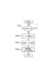
次に、キャリブレーション動作に関して述べる。図3は、キャリブレーション動作の1つである濃度補正制御に関するフローチャートである。このフローチャートの処理はCPU151により実行される。CPU151は、CPU101からフラグ/割り込み信号を受信したか否かを判断する(S301)。制御コントローラ部100のCPU101は、所定枚数の印刷が行われる毎に、CPU151に対して、フラグ/割り込み信号を出力するよう構成されている。CPU151は、CPU101からフラグ/割り込み信号を受けると、記録処理IC157に対して、不揮発RAM161に記憶されている濃度測定用画像データの出力を指示する(S302)。CPU101は、この濃度測定用画像データに基づいて中間転写ベルト8上に濃度測定用画像を形成する。なお、濃度測定用画像とは、所定サイズ/所定濃度の画像データに基づいて形成される画像であり、パッチ画像と呼ばれることもある。この濃度測定用画像の形成のためには、感光ドラム2a、2b、2c、2d、中間転写ベルト8の駆動、レーザユニット117の駆動や、帯電、現像、転写などの高圧出力が必要となり、画像形成装置の電力消費が発生する。
Next, the calibration operation will be described. FIG. 3 is a flowchart relating to density correction control which is one of the calibration operations. The process of this flowchart is executed by the
図4は、パッチ画像の構成を示す一例であり、各色成分毎に、感光ドラムの回転方向に直交する方向である主走査方向にH画素、感光ドラムの回転方向である副走査方向にV画素で構成される。 FIG. 4 shows an example of the configuration of the patch image. For each color component, H pixels in the main scanning direction, which is a direction orthogonal to the rotation direction of the photosensitive drum, and V pixels in the sub-scanning direction, which is the rotation direction of the photosensitive drum. Consists of.
CPU101は、中間転写ベルト8上に形成されたパッチ画像の濃度を濃度検知センサ132により読み取る。図5は、パッチ画像が濃度検知センサ132によって測定される様子を示している。CPU151は、濃度検知センサ132によって読み取られたデータをCPU101から取得する(S303)。パッチ画像を読み取った濃度が、パッチ画像を形成するための画像データが示す濃度レベルと同じであれば、特に問題はないが、電子写真方式においては、印刷枚数の増加とともに濃度特性に変化が生じる。例えば、濃度レベルを0〜255で表わす場合、例えば、濃度64のパッチ画像の読取濃度値が64を大きく上回ったり下回る場合がある。この濃度のずれ幅は、印刷装置内外の温度、湿度といった環境による影響と、どれだけの量のトナーを消費して印刷したかによって異なる。つまり、白い紙に対して、ベタに近い画像データを所定枚数分印刷した場合と、文字画像のように白部分の大きい比率の画像データを所定枚数分印刷した場合とでは、パッチ画像の濃度ずれ幅が異なる。濃度制御は、この濃度ずれを補正するものである。そこで、CPU151は、濃度検知センサ132によって読み取られた濃度に基づいて、画像形成に係わる条件を調整する。例えば、CPU151は、濃度ずれを補正する補正テーブルを更新する(S304)。
The
図6は、キャリブレーション動作の1つである色ずれ補正制御に関するCPU151のフローチャートである。画像処理コントローラ部150のCPU151は、制御コントローラ部100のCPU101からフラグ/割り込み信号が入力されたか否かを判断する(S601)。CPU101は、所定枚数の印刷が行われる毎に、CPU151に対して、フラグ/割り込み信号を出力するよう構成されている。CPU151は、前記フラグ/割り込み信号を受けると、記録処理IC157に対して、不揮発RAM161に記録されている色ずれ検知パターン画像データの出力を指示する(S602)。CPU101は、この色ずれ検知パターン画像データに基づいて、中間転写ベルト8上に色ずれ検知パターン画像を形成し、形成された色ずれ検知パターン画像を色ずれ検知センサ131、濃度検知センサ132により読み取る。
FIG. 6 is a flowchart of the
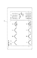
図7は、色ずれ検知パターン画像の構成を示す一例である。色ずれ検知センサ131は、中間転写ベルト8の搬送方向に対して直交する方向(主走査方向)に沿って少なくとも2つ配置される。このうち1つは、濃度検知センサ132と兼用で用いられる。図7において、パターン1を用いて中間転写ベルト8の搬送方向(副走査方向)のずれ量と主走査方向の傾きが検知され、パターン2を用いて主走査方向のずれ量と倍率が検知される。ブラックKの副走査方向のずれが発生すると、パターン1のdKs1が規定と異なるので、dKs1が規定値となるように補正が行われる。また、主走査方向のずれが発生すると、パターン2のdKm1とdKm2で示すスペースが規定値と異なる幅で検出されるので、これらが規定値になるように補正が行われる。また、主走査方向の傾きが発生すると、dKs2が0でなくなるので、dKs2が0になるように補正が行われる。また、主走査方向の位置により倍率が異なると、dKm1とdKm2の値が異なるので、これらが等しくなるように補正が行われる。なお、これらの各補正処理は周知技術であるので、詳細な説明は省略する。
FIG. 7 is an example showing the configuration of a color misregistration detection pattern image. At least two color
図8は、中間転写ベルト8に形成された色ずれ検知パターン画像が読み取られる様子を示す。中間転写ベルト8上に形成された色ずれ検知パターン画像(パターン1、パターン2)は、色ずれ検知センサ131、濃度検知センサ132で読み取られ、CPU101がずれ量を算出した結果をCPU151へ転送する。
FIG. 8 shows how the color misregistration detection pattern image formed on the
CPU151は、CPU101から色ずれ検知パターン画像を読み取った結果のデータを受け取り(S603)、受け取ったデータに基づいて色ずれをなくすための補正データを決定し、色ずれ補正テーブルを更新する(S604)。
The
図9は、ネットワークに接続される機器を示す図である。ネットワーク402に接続される複数の機器をまとめて画像形成システムと称す。本実施形態にかかる画像形成システムは、ネットワーク402に接続された画像形成装置190A、190B、190C、PC(パソコン)404A、404Bなどの装置が、ネットワーク402を介して電力管理装置401と接続されている。画像形成装置190Aには、電力計202が接続されており、電力計202は、交流電源201から供給される電力の消費量の累積(使用した電力量)を測定する。電力計202で測定された電力量は、画像形成装置190Aから電力管理装置401へ定期的に通知される。即ち、画像形成装置190Aの累積の使用電力量が電力管理装置401で管理される。画像形成装置190B,190Cにも同様に電力計が接続される。本画像形成システムでは、電力管理装置401が、ホストコンピュータとして働き、ネットワークシステム全体の使用電力量を管理することで、使用電力量の経費の増加抑制や、システムの安定稼動を行っている。画像形成装置が使用可能な残りの電力量(残りの使用可能な電力の累積)の取得に関しては、画像形成装置が電力管理装置401から定期的に受け取る構成とすればよい。或いは、画像形成装置が電力管理装置401から使用可能な電力量の初期値を受け取り、画像形成装置側で、その初期値から実際に使用した電力量を減算していくことにより、累積して使用可能な残りの電力量を取得する構成としてもよい。
FIG. 9 is a diagram illustrating devices connected to the network. A plurality of devices connected to the
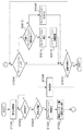
図10は、ネットワーク402に接続されている画像形成装置190Aに印刷ジョブが入力された場合の制御フローチャートを示す。他の画像形成装置190B,Cの制御は画像形成装置190Aと同様であるとする。また、画像形成装置190Aの構成は図2に示した構成であり、図10のフローチャートはCPU151により実行される。画像形成装置190Aに、印刷ジョブが入力されると、CPU151は、LANC158を介して、電力管理装置401に電力使用依頼を送信する(S1001)。CPU151は電力管理装置401からの電力使用依頼の応答を受信するのを待ち(S1002)、応答があると、その応答が画像形成可能であることを表しているか否かを判断する(S1003)。この応答には、画像形成可能を許可するか否か及び、使用可能な残電力量のデータが含まれる。画像形成が許可されていなければ、CPU151は、画像形成を実行できない旨の警告表示を操作部181へ表示させ(S1006)、処理を終了する。画像形成が許可されていれば、CPU151は、残電力量に応じて、キャリブレーションを実施する間隔を決定する(S1004)。
FIG. 10 is a control flowchart when a print job is input to the image forming apparatus 190 </ b> A connected to the
キャリブレーション間隔は、残電力量が多いほど短くなり、残電力量が少ないほど長くなる。例えば、残電力量が予め設定されている使用可能電力量Paの50%以上あれば、デフォルトの間隔Tdが設定される。残電力量が使用可能電力量Paの50〜30%の範囲であれば、キャリブレーション間隔はデフォルト間隔Tdの2倍の間隔となるように設定される。例えば、キャリブレーションの実施タイミングがデフォルトでは200枚の印刷が行われる毎である場合、400枚の印刷が行われる毎にキャリブレーションの実施タイミングとなる。残電力量が使用可能電力量Paの30〜10%であれば、キャリブレーション間隔はデフォルト間隔Tdの3倍となるように設定される。残電力量が使用可能電力量Paの10%未満であれば、キャリブレーション間隔はデフォルト間隔Tdの4倍となるように設定される。なお、これらのキャリブレーション間隔の値は一例であり、他の値であってもよい。 The calibration interval becomes shorter as the remaining power amount is larger, and becomes longer as the remaining power amount is smaller. For example, if the remaining power amount is 50% or more of the preset usable power amount Pa, the default interval Td is set. If the remaining power amount is in the range of 50 to 30% of the usable power amount Pa, the calibration interval is set to be twice the default interval Td. For example, when the calibration execution timing is 200 prints every time by default, the calibration execution timing is set every 400 prints. If the remaining power amount is 30 to 10% of the usable power amount Pa, the calibration interval is set to be three times the default interval Td. If the remaining power amount is less than 10% of the usable power amount Pa, the calibration interval is set to be four times the default interval Td. Note that these values of the calibration interval are examples, and other values may be used.
その後、CPU151は、CPU101に対して画像形成の開始を指示する(S1005)。CPU101は、画像形成の開始の指示を受けると、定着ヒータ116の温調制御やポリゴンモータの起動等の準備動作を開始し、準部動作が終了すると、画像形成を開始する。CPU101は、印刷ジョブの実行中に、予め設定されているキャリブレーションタイミングになると、CPU151へキャリブレーションのトリガ信号を送信する。このキャリブレーションタイミングは、上述した残電力量に応じて決められるキャリブレーション間隔のデフォルト枚数の印刷を行ったタイミングに相当する。あるいは、環境(温度、湿度)の変化が所定量以上あったタイミングに相当する。
Thereafter, the
CPU151は、CPU101からキャリブレーショントリガ信号を受信したか否かを判断する(S1009)。キャリブレーショントリガ信号が受信されていなければ、CPU151は、入力された印刷ジョブのすべての画像形成が終了したか否かを判断し(S1010)、終了すれば処理を終了する。キャリブレーショントリガ信号を受信した場合、CPU151は、前回のキャリブレーションを実行してからS1004で決定したキャリブレーション間隔(印刷枚数)に到達しているか否かを判断する(S1013)。前回のキャリブレーションを実行してから決定したキャリブレーション間隔に到達していれば、CPU151は、図3或いは図6で示したキャリブレーション動作を実行させる(S1014)。この時、キャリブレーション実行した印刷枚数や、温度等の条件と、補正係数を不揮発RAM120に記憶する(S1015)。
The
前回のキャリブレーションを実行してから決定したキャリブレーション間隔に到達していなければ、キャリブレーション予測補正を実行する(S1016)。キャリブレーション予測補正とは、画像形成部でパッチ画像を形成することなく、不揮発RAM120に記憶された過去の複数回分のキャリブレーション結果に基づいて補正係数を決定する予測キャリブレーション動作である。例えば、CPU151は、過去複数回分のキャリブレーション結果と、前回キャリブレーションを実行してからの印刷枚数、環境変化の量に基づいて、印刷枚数と環境変化が近い複数の結果を平均化して、補正係数を予測する。以上の処理は、入力された印刷ジョブが終了するまで繰り返される。
If the calibration interval determined after the previous calibration is not reached, calibration prediction correction is executed (S1016). The calibration prediction correction is a prediction calibration operation that determines a correction coefficient based on a plurality of past calibration results stored in the nonvolatile RAM 120 without forming a patch image by the image forming unit. For example, the
図11は、画像形成装置190Aの使用可能電力量とキャリブレーション間隔を示したグラフである。縦軸は、画像形成装置190Aが使用可能な電力量を示し、横軸は、キャリブレーション動作を何枚毎に行うかの間隔を示している。CPU151は、電力管理装置401から受信した使用可能電力量(残電力量)を所定値と比較する。即ちCPU151は、残電力量がどの範囲に入るか確認する。ここで、P1は予め決められている最初の使用可能電力量の50%に相当する値である。同様に、P2は30%、P3は10%に相当する。使用可能電力量が、P1以上の場合、パッチ画像を形成するキャリブレーションはTC1(前述のTdに相当)枚の画像形成毎に実行される。この回数は、画像形成装置の初期値として設定されている枚数である。使用可能電力量がP1〜P2の範囲の場合、キャリブレーション間隔は、TC2枚毎になり、使用可能電力がP1以上の場合に比べてキャリブレーション間隔が広げる。同様に、使用可能電力量がP2〜P3の場合、キャリブレーション間隔はTC3枚毎に広がり、使用可能電力量がP3以下の場合、キャリブレーション間隔はTC4枚毎に広がる。このように、使用可能電力量が少なくなるほど、キャリブレーション間隔が広がることで、画像形成装置の消費電力を低減する。
FIG. 11 is a graph showing the usable electric energy and the calibration interval of the
図12は、画像形成装置の使用可能電力とキャリブレーション間隔を示したタイミングチャートである。画像形成装置190AがTC1枚数の印刷を行うと、キャリブレーションを実施するためのキャリブレーショントリガ信号が発生される。使用可能電力量がP1以上の場合、キャリブレーショントリガが発生する毎即ち、TC1枚の印刷毎に、パッチ画像形成を伴うキャリブレーション動作が実行される。使用可能電力量がP1〜P2の場合、キャリブレーション動作は、TC2枚の印刷毎に行われる。この場合、2n−1個目(nは自然数)のキャリブレーショントリガ信号に対しては、キャリブレーションが行われないことになるがこのタイミングでは、過去に行ったキャリブレーション動作結果より、補正係数を予測(算出)して補正を行う。この補正は、過去の複数回のキャリブレーション結果から、前回のキャリブレーション実行時からの印刷枚数と温度変化が近い複数の結果を平均化して、補正係数を決定する。即ち、パッチ画像が形成されることなく補正係数が決定されるので、電力消費が抑えられる。同様に使用可能電力量がP2〜P3の場合、TC3枚の印刷毎にキャリブレーション動作が実行され、3n−2個目及び3n−1個目のキャリブレーショントリガ信号に対しては予測補正が行われる。使用可能電力量がP3以下の場合、TC4枚の印刷毎にキャリブレーション動作が行われ、4n−3個目、4n−2個目、4n−1個目のキャリブレーショントリガ信号に対しては予測補正が行われる。
FIG. 12 is a timing chart showing the usable power and the calibration interval of the image forming apparatus. When the
上述した実施形態では、使用可能電力量P1〜P3を予め設定されている最初の使用可能電力量に対する割合として説明したが、割合ではなく、P1〜P3を電力量の値としてもよい。 In the above-described embodiment, the available power amounts P1 to P3 have been described as the ratio to the first preset usable power amount, but P1 to P3 may be used as the power amount value instead of the ratio.
このように、TC1枚の印刷毎に発生するキャリブレーショントリガ信号に対して、予測制御と実キャリブレーションを適切に行うことで、消費電力を抑えながら画像品質劣化を防止することできる。 As described above, by appropriately performing the predictive control and the actual calibration for the calibration trigger signal generated every time TC1 is printed, it is possible to prevent image quality deterioration while suppressing power consumption.
(第2の実施の形態)
第2の実施形態では、過去の使用電力量の履歴から今後の使用電力量を予測し、予測した結果に基づいてキャリブレーション間隔を決定するものである。
(Second Embodiment)
In the second embodiment, the future power consumption is predicted from the history of the past power consumption, and the calibration interval is determined based on the predicted result.
図13は、過去3ヶ月間の画像形成装置の使用電力量を1週間毎に積算した図を示す。ここでは、画像形成装置で使用可能な電力量が、1ヶ月毎に設定されている場合について述べる。なお、説明の簡略化のため、1カ月を4週間として説明する。また、図において、wは週を表しており、斜線部分が各週の使用電力量を表している。3ヶ月前の1週目の使用電力量がPn1−2、2週目の使用電力量がPn2−2、3週目の使用電力量がPn3−2、4週目の使用電力量がPn4−2とする。今月の月初めに過去3ヶ月の平均使用電力量から、CPU151は今月の各週の使用電力量を推測する。今月1週目の使用電力量予測値をPn1、2週目の使用電力量の予測値をPn2、3週目の使用電力量の予測値をPn3、4週目の使用電力量の予測値をPn4とすると、Pn1〜Pn4は以下のように算出される。
Pn1=((Pn1−3)+(Pn1−2)+(Pn1−1))/3
Pn2=((Pn2−3)+(Pn2−2)+(Pn2−1))/3
Pn3=((Pn3−3)+(Pn3−2)+(Pn3−1))/3
Pn4=((Pn4−3)+(Pn4−2)+(Pn4−1))/3
CPU151は、算出された使用電力量の予測値から、キャリブレーション間隔を設定する。
FIG. 13 is a diagram in which the power consumption of the image forming apparatus for the past three months is integrated every week. Here, a case where the amount of power that can be used in the image forming apparatus is set every month will be described. For the sake of simplicity of explanation, one month is assumed to be four weeks. In the figure, w represents a week, and the shaded portion represents the amount of power used for each week. The power consumption of the
Pn1 = ((Pn1-3) + (Pn1-2) + (Pn1-1)) / 3
Pn2 = ((Pn2-3) + (Pn2-2) + (Pn2-1)) / 3
Pn3 = ((Pn3-3) + (Pn3-2) + (Pn3-1)) / 3
Pn4 = ((Pn4-3) + (Pn4-2) + (Pn4-1)) / 3
The
図14は、1ヶ月(今月)の画像形成装置で使用可能な電力量と、過去の画像形成装置の使用電力量から予測した予測電力量、及び実使用電力量の関係を示す図である。1ヶ月の画像形成装置の使用可能電力量をPtとすると、図14(a)のようにPtが1ヶ月の使用電力量予測値以上の場合(Pt≧Pn1+Pn2+Pn3+Pn4)、キャリブレーショントリガ毎にキャリブレーションが行われる。 FIG. 14 is a diagram illustrating the relationship between the amount of power that can be used in the image forming apparatus for one month (this month), the predicted power amount that is predicted from the past power consumption amount of the image forming apparatus, and the actual power consumption amount. Assuming that the usable electric energy of the image forming apparatus for one month is Pt, when Pt is equal to or larger than the predicted electric energy consumption for one month as shown in FIG. 14A (Pt ≧ Pn1 + Pn2 + Pn3 + Pn4), calibration is performed for each calibration trigger. Is done.
図14(b)にようにPtが1ヶ月の使用電力量の予測値よりも小さい場合(Pt<Pn1+Pn2+Pn3+Pn4)、第1の実施形態で説明したキャリブレーションの予測制御が行われる。 As shown in FIG. 14B, when Pt is smaller than the predicted value of power consumption for one month (Pt <Pn1 + Pn2 + Pn3 + Pn4), the calibration prediction control described in the first embodiment is performed.
1週目のキャリブレーション間隔の設定方法に関して述べる。図14(c)のPd1は、1ヶ月の使用可能電力量を4週間で均等割りしたPt/4から、過去3ヶ月の履歴から予測した1週目の電力量Pn1を減算した電力を示す。Pd1>P1の場合、キャリブレーショントリガ毎に、キャリブレーション動作が行われる。P2<Pd1≦P1の場合、キャリブレーション間隔は、TC2枚の印刷毎になる。同様に、P3<Pd1≦P2の場合、キャリブレーション間隔は、TC3枚の印刷毎になり、Pd1≦P3の場合、キャリブレーション間隔は、TC4枚の印刷毎になる。 A method for setting the calibration interval for the first week will be described. Pd1 in FIG. 14C indicates power obtained by subtracting the power amount Pn1 of the first week predicted from the history of the past three months from Pt / 4 obtained by equally dividing the usable power amount of one month in four weeks. In the case of Pd1> P1, a calibration operation is performed for each calibration trigger. In the case of P2 <Pd1 ≦ P1, the calibration interval is every printing of TC2. Similarly, when P3 <Pd1 ≦ P2, the calibration interval is every TC3 printing, and when Pd1 ≦ P3, the calibration interval is every TC4 printing.
次に2週目のキャリブレーション間隔の設定に関して述べる。1週目に使用した実電力量をPa1とすると、図14(d)のようにPtから1週目の実使用電力量を減算した値が2〜4週目の使用電力量の予測値以上である場合(Pt−Pa1≧Pn2+Pn3+Pn4)、キャリブレーショントリガ毎にキャリブレーションが行われる。 Next, the setting of the calibration interval for the second week will be described. Assuming that the actual electric energy used in the first week is Pa1, the value obtained by subtracting the actual electric energy used in the first week from Pt is equal to or more than the predicted value of the electric energy used in the second to fourth weeks as shown in FIG. (Pt−Pa1 ≧ Pn2 + Pn3 + Pn4), calibration is performed for each calibration trigger.
Ptから1週目の実使用電力量を減算した値が2〜4週目の使用電力量の予測値よりも小さい場合(Pt−Pa1<Pn2+Pn3+Pn4)、キャリブレーションの予測制御が行われる。 When the value obtained by subtracting the actual power consumption in the first week from Pt is smaller than the predicted value of the power consumption in the second to fourth weeks (Pt−Pa1 <Pn2 + Pn3 + Pn4), calibration prediction control is performed.
2週目のキャリブレーション間隔の設定方法に関して述べる。図14(f)のPd2は、1ヶ月の使用可能電力量から、1週目に使用した実電力量Pa1を引き、残り3週間で均等割りした(Pt−Pa1)/3から、過去3ヶ月の履歴から予測した2週目の電力量Pn2を引いた電力量を示す。Pd2>P1の場合、キャリブレーショントリガ毎に、キャリブレーション動作が行われる。P2<Pd2≦P1の場合、キャリブレーション間隔は、TC2枚の印刷毎になる。同様に、P3<Pd2≦P2の場合、キャリブレーション間隔は、TC3枚の印刷毎になる。広げ、Pd2≦P3の場合、キャリブレーション間隔は、TC4枚の印刷毎になる。 A method for setting the calibration interval for the second week will be described. Pd2 in FIG. 14 (f) is obtained by subtracting the actual power amount Pa1 used in the first week from the usable power amount in one month, and equally dividing (Pt−Pa1) / 3 in the remaining three weeks, and the past three months. The electric energy which subtracted electric energy Pn2 of the 2nd week estimated from this log | history is shown. In the case of Pd2> P1, a calibration operation is performed for each calibration trigger. In the case of P2 <Pd2 ≦ P1, the calibration interval is every printing of TC2. Similarly, when P3 <Pd2 ≦ P2, the calibration interval is every TC3 print. If Pd2 ≦ P3, the calibration interval is every TC4 print.
3週目に関しても同様に算出する。1週目に使用した実電力量をPa1、2週目に使用した実電力量をPa2とすると、図14(g)のように、(Pt−Pa1−Pa2)≧Pn3+Pn4の場合、キャリブレーショントリガ毎にキャリブレーションが行われる。一方、図14(h)のように、(Pt−Pa1−Pa2)/2<Pn3+Pn4の場合、キャリブレーションの予測制御が行われる。 The same calculation is performed for the third week. Assuming that the actual electric energy used in the first week is Pa1 and the actual electric energy used in the first week is Pa2, as shown in FIG. 14 (g), in the case of (Pt−Pa1−Pa2) ≧ Pn3 + Pn4, the calibration trigger Calibration is performed every time. On the other hand, as shown in FIG. 14H, in the case of (Pt−Pa1−Pa2) / 2 <Pn3 + Pn4, calibration prediction control is performed.
3週目のキャリブレーション間隔の設定方法に関して述べる。図14(i)のPd3は、1ヶ月の使用可能電力量から、1週目に使用した実電力量Pa1と2週目に使用した実電力量Pa2を引き、残り2週間で均等割りした(Pt−Pa1−Pa2)/2から、過去3ヶ月の履歴から予測した3週目の電力量Pn3を引いた電力量を示す。Pd3>P1の場合、キャリブレーショントリガ毎に、キャリブレーションが行われる。P2<Pd3≦P1の場合、キャリブレーション間隔は、TC2枚の印刷毎になる。同様に、P3<Pd3≦P2の場合、キャリブレーション間隔は、TC3枚の印刷毎になり、Pd3≦P3の場合、キャリブレーション間隔は、TC4枚の印刷毎になる。 A method for setting the calibration interval for the third week will be described. Pd3 in FIG. 14 (i) is obtained by subtracting the actual power amount Pa1 used in the first week and the actual power amount Pa2 used in the second week from the usable power amount in one month, and equally dividing the remaining two weeks ( The electric energy obtained by subtracting the electric energy Pn3 in the third week predicted from the history of the past three months from Pt-Pa1-Pa2) / 2 is shown. When Pd3> P1, calibration is performed for each calibration trigger. When P2 <Pd3 ≦ P1, the calibration interval is every TC2 print. Similarly, when P3 <Pd3 ≦ P2, the calibration interval is every TC3 printing, and when Pd3 ≦ P3, the calibration interval is every TC4 printing.
4週目のキャリブレーション間隔の設定方法に関して述べる。図14(g)のPd4は、1ヶ月の使用可能電力量から、1〜3週目にそれぞれ使用した実電力量Pa1,Pa2,Pa3を引いた値(Pt−Pa1−Pa2−Pa3)から、過去3ヶ月の履歴から予測した4週目の電力量Pn4を引いた電力量を示す。Pd4>P1の場合、キャリブレーショントリガ毎に、キャリブレーションが行われる。P2<Pd4≦P1の場合、キャリブレーション間隔はTC2枚の印刷毎になる。同様に、P3<Pd4≦P2の場合、キャリブレーション間隔はTC3枚の印刷毎になり、Pd4≦P3の場合、キャリブレーション間隔はTC4枚の印刷毎になる。 A method for setting the calibration interval for the fourth week will be described. Pd4 of FIG.14 (g) is from the value (Pt-Pa1-Pa2-Pa3) which subtracted the actual electric energy Pa1, Pa2, Pa3 each used for the 1st-3rd week from the usable electric energy of one month, The electric energy obtained by subtracting the electric energy Pn4 in the fourth week predicted from the history of the past three months is shown. When Pd4> P1, calibration is performed for each calibration trigger. In the case of P2 <Pd4 ≦ P1, the calibration interval is every TC2 print. Similarly, when P3 <Pd4 ≦ P2, the calibration interval is every TC3 printing, and when Pd4 ≦ P3, the calibration interval is every TC4 printing.
このように、画像形成装置が予め決められた期間に使用可能な電力量と過去に画像形成装置が使用した電力量との比較結果に基づいてキャリブレーション間隔を広げることで、画像形成装置の消費電力量を低減する。また、TC1枚の印刷毎に発生するキャリブレーショントリガに対して、予測制御と実キャリブレーションを適切に行うことで、使用電力量を抑えつつ、画像品質劣化を防止することできる。 As described above, the consumption of the image forming apparatus is increased by widening the calibration interval based on the comparison result between the amount of power that can be used by the image forming apparatus in a predetermined period and the amount of power that has been used by the image forming apparatus in the past. Reduce the amount of power. Further, by appropriately performing predictive control and actual calibration for a calibration trigger that occurs every time one TC is printed, image quality deterioration can be prevented while suppressing power consumption.
また、上述した実施形態では、1台の画像形成装置で使用可能な電力量を制限することについて説明したが、ネットワーク402に接続されている複数の画像形成装置の使用電力量の合計が制限される構成であってもよい。
In the above-described embodiment, the description has been given of limiting the amount of power that can be used by one image forming apparatus. However, the total amount of power used by a plurality of image forming apparatuses connected to the
100 制御コントローラ部
101 CPU
131 色ずれ検知センサ
132 濃度検知センサ
150 画像処理コントローラ部
151 CPU
180 画像形成ユニット
190 画像形成装置
401 電力管理装置
402 ネットワーク
100
131 Color
180 Image forming unit 190
Claims (7)
前記画像形成手段を動作させて画像形成に係わる条件を調整するためのキャリブレーション動作を定期的に実行するキャリブレーション手段と、
を有し、所定の期間における使用電力量が制限される画像形成装置において、
前記画像形成装置が使用可能な残りの電力量を取得する取得手段と、
前記取得手段により取得される残りの電力量に基づいて前記キャリブレーション動作を実行する間隔を決定し、決定した間隔が到達すると前記キャリブレーション動作を実行させる制御手段と、
前記キャリブレーション動作の結果を記憶する記憶手段と、
所定枚数の画像形成を行う毎にトリガ信号を発生する発生手段と、
前記発生手段により前記トリガ信号が発生されたタイミングが前記制御手段により決定されるキャリブレーション動作の間隔に基づくキャリブレーション動作を実行するタイミングでない場合、前記記憶手段に記憶される過去に実行されたキャリブレーション動作の結果に基づいて、画像形成に係わる条件を調整する予測キャリブレーションを実行する予測キャリブレーション手段と、
を有することを特徴とする画像形成装置。 An image forming means for forming an image;
Calibration means for periodically performing a calibration operation for operating the image forming means to adjust conditions relating to image formation;
In the image forming apparatus in which the amount of power used in a predetermined period is limited,
Acquisition means for acquiring the remaining amount of power that can be used by the image forming apparatus;
Control means for determining an interval for executing the calibration operation based on the remaining electric energy acquired by the acquisition means, and for executing the calibration operation when the determined interval is reached;
Storage means for storing the result of the calibration operation;
Generating means for generating a trigger signal each time a predetermined number of images are formed;
If the timing at which the trigger signal is generated by the generating means is not the timing for executing the calibration operation based on the interval of the calibration operation determined by the control means, the calibration executed in the past stored in the storage means Predictive calibration means for executing predictive calibration for adjusting the conditions related to image formation based on the result of the calibration operation;
An image forming apparatus comprising:
前記予測キャリブレーション手段は、前記測定用の画像を形成することなく、前記キャリブレーション手段により過去に実行されたキャリブレーション動作の結果に基づいて、画像形成に係わる条件を調整することを特徴とする請求項1記載の画像形成装置。 The calibration unit adjusts the conditions related to the image formation by forming an image for measurement by the image forming unit and reading the image for measurement.
The predictive calibration unit adjusts a condition related to image formation based on a result of a calibration operation performed in the past by the calibration unit without forming the measurement image. The image forming apparatus according to claim 1 .
前記取得手段は、前記ネットワークに接続される電力管理装置から使用可能な残りの電力量を取得することを特徴とする請求項1乃至5の何れか1項に記載の画像形成装置。 The image forming apparatus is connected to a network;
The acquisition unit, an image forming apparatus according to any one of claims 1 to 5, characterized in that to obtain the remaining amount of power available from the power management device connected to the network.
前記画像形成手段を動作させて画像形成に係わる条件を調整するためのキャリブレーション動作を定期的に実行するキャリブレーション手段と、
を有し、所定の期間における使用電力量が制限される画像形成装置において、
前記画像形成装置が使用可能な残りの電力量を取得する取得手段と、
前記画像形成装置が使用した過去の使用電力量を記憶する電力量記憶手段と、
前記電力量記憶手段に記憶された使用電力量と前記取得手段により取得される残りの電力量に基づいて前記キャリブレーション動作を実行する間隔を決定し、決定した間隔が到達すると前記キャリブレーション動作を実行させる制御手段と、
を有することを特徴とする画像形成装置。 An image forming means for forming an image;
Calibration means for periodically performing a calibration operation for operating the image forming means to adjust conditions relating to image formation;
In the image forming apparatus in which the amount of power used in a predetermined period is limited,
Acquisition means for acquiring the remaining amount of power that can be used by the image forming apparatus;
An electric energy storage means for storing past electric energy used by the image forming apparatus ;
An interval for executing the calibration operation is determined based on the used electric energy stored in the electric energy storage unit and the remaining electric energy acquired by the acquisition unit, and the calibration operation is performed when the determined interval is reached. Control means to be executed;
Images forming device you characterized Rukoto to have a.
Priority Applications (2)
| Application Number | Priority Date | Filing Date | Title |
|---|---|---|---|
| JP2010282235A JP5677075B2 (en) | 2010-12-17 | 2010-12-17 | Image forming system |
| US13/323,351 US8625176B2 (en) | 2010-12-17 | 2011-12-12 | Image forming apparatus configured to perform a calibration operation |
Applications Claiming Priority (1)
| Application Number | Priority Date | Filing Date | Title |
|---|---|---|---|
| JP2010282235A JP5677075B2 (en) | 2010-12-17 | 2010-12-17 | Image forming system |
Publications (3)
| Publication Number | Publication Date |
|---|---|
| JP2012128365A JP2012128365A (en) | 2012-07-05 |
| JP2012128365A5 JP2012128365A5 (en) | 2014-02-13 |
| JP5677075B2 true JP5677075B2 (en) | 2015-02-25 |
Family
ID=46234019
Family Applications (1)
| Application Number | Title | Priority Date | Filing Date |
|---|---|---|---|
| JP2010282235A Expired - Fee Related JP5677075B2 (en) | 2010-12-17 | 2010-12-17 | Image forming system |
Country Status (2)
| Country | Link |
|---|---|
| US (1) | US8625176B2 (en) |
| JP (1) | JP5677075B2 (en) |
Families Citing this family (8)
| Publication number | Priority date | Publication date | Assignee | Title |
|---|---|---|---|---|
| JP5728216B2 (en) * | 2010-12-13 | 2015-06-03 | キヤノン株式会社 | Image forming system and server apparatus |
| JP2014085379A (en) * | 2012-10-19 | 2014-05-12 | Ricoh Co Ltd | Image forming apparatus, image forming method, program, and recording medium |
| JP5990093B2 (en) * | 2012-11-29 | 2016-09-07 | キヤノン株式会社 | Image processing apparatus, image processing method, and program |
| JP6900916B2 (en) * | 2018-01-31 | 2021-07-07 | 京セラドキュメントソリューションズ株式会社 | Image forming device |
| US10987942B2 (en) * | 2018-02-01 | 2021-04-27 | Fujitsu Component Limited | Printing apparatus |
| JP7293861B2 (en) * | 2019-05-24 | 2023-06-20 | 京セラドキュメントソリューションズ株式会社 | IMAGE FORMING APPARATUS AND IMAGE FORMING APPARATUS CONTROL METHOD |
| JP2022187813A (en) * | 2021-06-08 | 2022-12-20 | 株式会社リコー | Image forming apparatus, image forming system, and image forming method |
| JP2023057241A (en) * | 2021-10-11 | 2023-04-21 | キヤノン株式会社 | Image forming apparatus |
Family Cites Families (14)
| Publication number | Priority date | Publication date | Assignee | Title |
|---|---|---|---|---|
| JP3496652B2 (en) * | 2001-03-30 | 2004-02-16 | ミノルタ株式会社 | Image processing system, management device, image processing device, management method, management program, and recording medium |
| JP2003209924A (en) * | 2002-01-11 | 2003-07-25 | Ricoh Co Ltd | Power consumption management system |
| JP4100550B2 (en) * | 2002-09-20 | 2008-06-11 | 株式会社リコー | Color image forming apparatus |
| US7408682B2 (en) * | 2003-03-20 | 2008-08-05 | Kabushiki Kaisha Toshiba | Image reading apparatus |
| JP2005017459A (en) | 2003-06-24 | 2005-01-20 | Kyocera Mita Corp | Image forming apparatus |
| JP4093180B2 (en) * | 2003-12-09 | 2008-06-04 | コニカミノルタビジネステクノロジーズ株式会社 | Image forming apparatus |
| EP1632822B1 (en) * | 2004-09-06 | 2017-04-05 | Canon Kabushiki Kaisha | Image forming apparatus and image forming method |
| JP4175346B2 (en) * | 2005-06-30 | 2008-11-05 | ブラザー工業株式会社 | Image conversion program, control method, and image data processing system |
| JP4846357B2 (en) * | 2005-12-07 | 2011-12-28 | 株式会社リコー | Power monitoring network system |
| JP4890887B2 (en) * | 2006-03-07 | 2012-03-07 | キヤノン株式会社 | Image forming apparatus |
| JP4956133B2 (en) * | 2006-10-11 | 2012-06-20 | キヤノン株式会社 | Image forming apparatus |
| JP4927577B2 (en) * | 2007-01-31 | 2012-05-09 | 京セラミタ株式会社 | Image forming apparatus |
| JP5035605B2 (en) * | 2007-02-28 | 2012-09-26 | 富士ゼロックス株式会社 | Image processing apparatus, image processing system, power saving apparatus, and power saving program |
| JP5418454B2 (en) * | 2010-09-24 | 2014-02-19 | コニカミノルタ株式会社 | Image forming apparatus and operation plan creation method |
-
2010
- 2010-12-17 JP JP2010282235A patent/JP5677075B2/en not_active Expired - Fee Related
-
2011
- 2011-12-12 US US13/323,351 patent/US8625176B2/en not_active Expired - Fee Related
Also Published As
| Publication number | Publication date |
|---|---|
| JP2012128365A (en) | 2012-07-05 |
| US8625176B2 (en) | 2014-01-07 |
| US20120154834A1 (en) | 2012-06-21 |
Similar Documents
| Publication | Publication Date | Title |
|---|---|---|
| JP5677075B2 (en) | Image forming system | |
| JP4622206B2 (en) | Color image forming apparatus | |
| JP4393416B2 (en) | Image forming apparatus and program | |
| JP5196979B2 (en) | Image forming apparatus and color misregistration correction method | |
| JP4923726B2 (en) | Image forming apparatus and image forming method | |
| JP5587349B2 (en) | Image forming apparatus | |
| JP2007078874A (en) | Image forming apparatus, image information detection method therefor, and program | |
| JP2008020818A (en) | Image forming apparatus and image stabilization method | |
| US9523954B2 (en) | Image forming apparatus that performs developer replenishment | |
| JP4904982B2 (en) | Developing device, image forming apparatus, and program. | |
| JP2009276517A (en) | Image forming apparatus | |
| JP2008020695A (en) | Image forming apparatus | |
| JP5304618B2 (en) | Image forming apparatus | |
| US8081891B2 (en) | Image quality adjustment method, image forming apparatus and computer readable medium | |
| JP2010164891A (en) | Control method for image forming and fixing conditions, image forming apparatus, program, and storage medium | |
| JP2010230966A (en) | Apparatus for detecting the amount of remaining toner and image forming apparatus using the same | |
| JP2008048165A (en) | Image forming apparatus and calibration method | |
| JP2005202099A (en) | Image forming apparatus | |
| JP2010256823A (en) | Image forming apparatus | |
| JP2011154109A (en) | Image forming apparatus | |
| JP7192629B2 (en) | Image forming apparatus and its control method | |
| JP4968296B2 (en) | Image forming apparatus and image forming method | |
| JP4890324B2 (en) | Image forming apparatus | |
| JP2008135805A (en) | Image forming apparatus | |
| JP2008233351A (en) | Image forming apparatus |
Legal Events
| Date | Code | Title | Description |
|---|---|---|---|
| A521 | Written amendment |
Free format text: JAPANESE INTERMEDIATE CODE: A523 Effective date: 20131217 |
|
| A621 | Written request for application examination |
Free format text: JAPANESE INTERMEDIATE CODE: A621 Effective date: 20131217 |
|
| A977 | Report on retrieval |
Free format text: JAPANESE INTERMEDIATE CODE: A971007 Effective date: 20140905 |
|
| A131 | Notification of reasons for refusal |
Free format text: JAPANESE INTERMEDIATE CODE: A131 Effective date: 20140909 |
|
| A521 | Written amendment |
Free format text: JAPANESE INTERMEDIATE CODE: A523 Effective date: 20141110 |
|
| TRDD | Decision of grant or rejection written | ||
| A01 | Written decision to grant a patent or to grant a registration (utility model) |
Free format text: JAPANESE INTERMEDIATE CODE: A01 Effective date: 20141202 |
|
| A61 | First payment of annual fees (during grant procedure) |
Free format text: JAPANESE INTERMEDIATE CODE: A61 Effective date: 20141226 |
|
| LAPS | Cancellation because of no payment of annual fees |