JP5751952B2 - Image forming apparatus and image forming apparatus control method - Google Patents
Image forming apparatus and image forming apparatus control method Download PDFInfo
- Publication number
- JP5751952B2 JP5751952B2 JP2011142868A JP2011142868A JP5751952B2 JP 5751952 B2 JP5751952 B2 JP 5751952B2 JP 2011142868 A JP2011142868 A JP 2011142868A JP 2011142868 A JP2011142868 A JP 2011142868A JP 5751952 B2 JP5751952 B2 JP 5751952B2
- Authority
- JP
- Japan
- Prior art keywords
- image forming
- forming apparatus
- information
- chart
- data
- Prior art date
- Legal status (The legal status is an assumption and is not a legal conclusion. Google has not performed a legal analysis and makes no representation as to the accuracy of the status listed.)
- Expired - Fee Related
Links
Images


Classifications
-
- G—PHYSICS
- G03—PHOTOGRAPHY; CINEMATOGRAPHY; ANALOGOUS TECHNIQUES USING WAVES OTHER THAN OPTICAL WAVES; ELECTROGRAPHY; HOLOGRAPHY
- G03G—ELECTROGRAPHY; ELECTROPHOTOGRAPHY; MAGNETOGRAPHY
- G03G15/00—Apparatus for electrographic processes using a charge pattern
- G03G15/50—Machine control of apparatus for electrographic processes using a charge pattern, e.g. regulating differents parts of the machine, multimode copiers, microprocessor control
- G03G15/5062—Machine control of apparatus for electrographic processes using a charge pattern, e.g. regulating differents parts of the machine, multimode copiers, microprocessor control by measuring the characteristics of an image on the copy material
-
- G—PHYSICS
- G03—PHOTOGRAPHY; CINEMATOGRAPHY; ANALOGOUS TECHNIQUES USING WAVES OTHER THAN OPTICAL WAVES; ELECTROGRAPHY; HOLOGRAPHY
- G03G—ELECTROGRAPHY; ELECTROPHOTOGRAPHY; MAGNETOGRAPHY
- G03G15/00—Apparatus for electrographic processes using a charge pattern
- G03G15/50—Machine control of apparatus for electrographic processes using a charge pattern, e.g. regulating differents parts of the machine, multimode copiers, microprocessor control
- G03G15/5075—Remote control machines, e.g. by a host
- G03G15/5079—Remote control machines, e.g. by a host for maintenance
-
- H—ELECTRICITY
- H04—ELECTRIC COMMUNICATION TECHNIQUE
- H04N—PICTORIAL COMMUNICATION, e.g. TELEVISION
- H04N1/00—Scanning, transmission or reproduction of documents or the like, e.g. facsimile transmission; Details thereof
- H04N1/46—Colour picture communication systems
- H04N1/56—Processing of colour picture signals
- H04N1/60—Colour correction or control
-
- G—PHYSICS
- G03—PHOTOGRAPHY; CINEMATOGRAPHY; ANALOGOUS TECHNIQUES USING WAVES OTHER THAN OPTICAL WAVES; ELECTROGRAPHY; HOLOGRAPHY
- G03G—ELECTROGRAPHY; ELECTROPHOTOGRAPHY; MAGNETOGRAPHY
- G03G2215/00—Apparatus for electrophotographic processes
- G03G2215/01—Apparatus for electrophotographic processes for producing multicoloured copies
- G03G2215/0151—Apparatus for electrophotographic processes for producing multicoloured copies characterised by the technical problem
- G03G2215/0164—Uniformity control of the toner density at separate colour transfers
Landscapes
- Engineering & Computer Science (AREA)
- Microelectronics & Electronic Packaging (AREA)
- Physics & Mathematics (AREA)
- General Physics & Mathematics (AREA)
- Multimedia (AREA)
- Signal Processing (AREA)
- Facsimile Image Signal Circuits (AREA)
- Color Image Communication Systems (AREA)
- Accessory Devices And Overall Control Thereof (AREA)
- Color, Gradation (AREA)
Description
本発明は色を補正するための画像形成装置及び画像形成装置の制御方法に関するものである。 The present invention relates to an image forming apparatus for correcting color and a method for controlling the image forming apparatus.
近年、カラープリンタ、カラー複写機等の電子写真方式やインクジェット方式等を採用したカラー画像形成装置には、出力画像の高画質化が求められている。特に、濃度の階調と色の安定性は、画像品質の良し悪しの判断に大きな影響を与える。 In recent years, color image forming apparatuses employing an electrophotographic system such as a color printer or a color copying machine, an ink jet system, and the like have been required to improve the output image quality. In particular, density gradation and color stability have a great influence on the judgment of image quality.
特に電子写真方式のカラー画像形成装置においては、わずかな環境変動でも濃度の変動が生じてしまうので、常に一定の濃度の階調性を保つための手段を持つ必要がある。 In particular, in an electrophotographic color image forming apparatus, since a change in density occurs even with a slight environmental change, it is necessary to have means for always maintaining a constant density gradation.
そこで、従来のカラー画像形成装置においては電子写真方式の感光ドラム上もしくは1次転写ベルト上に濃度を検出するセンサを設け、C(シアン)、M(マゼンタ)、Y(イエロー)、K(ブラック)各色の階調特性を測定している。そして各色に対する1次元の階調補正用のLUT(Look Up Table)を作成するキャリブレーション技術が搭載されている。LUTとは、特定の間隔で区切られた入力データに対応した出力データを示すテーブルであり、演算式では表せない非線形な特性を表現することが可能である。1次元の階調補正用のLUTはC、M、Y、Kの各入力信号値を表現可能な画像形成装置側の各出力信号値を表している。画像形成装置は、この出力信号値に対応したトナーを使って紙上に画像を形成する。 Therefore, in the conventional color image forming apparatus, a sensor for detecting the density is provided on the electrophotographic photosensitive drum or the primary transfer belt, and C (cyan), M (magenta), Y (yellow), K (black). ) The gradation characteristics of each color are measured. A calibration technique for creating a one-dimensional tone correction LUT (Look Up Table) for each color is installed. The LUT is a table indicating output data corresponding to input data divided at specific intervals, and can express non-linear characteristics that cannot be expressed by arithmetic expressions. The one-dimensional gradation correction LUT represents output signal values on the image forming apparatus side that can express C, M, Y, and K input signal values. The image forming apparatus forms an image on paper using toner corresponding to the output signal value.
1次元のLUTを作成する際にはC、M、Y、Kの各トナーに対応した階調の異なるデータのパッチで構成されたチャートを用意して画像形成装置で出力する。画像形成装置で出力されたチャートの値を、画像形成装置の前述のセンサやスキャナ、あるいは画像形成装置以外の色測定器(測色器)等を用いて読み取る。読み取った値を予め持っているターゲットデータと比較することでCMYK独立に補正用の1次元のLUTを作成するのである。 When creating a one-dimensional LUT, a chart composed of patches of data with different gradations corresponding to C, M, Y, and K toners is prepared and output by the image forming apparatus. The chart value output by the image forming apparatus is read using the above-described sensor or scanner of the image forming apparatus, or a color measuring device (color measuring device) other than the image forming apparatus. A one-dimensional LUT for correction is created independently of CMYK by comparing the read value with target data already possessed.
しかし、1次元のLUTで単色の階調特性を補正してもレッド、グリーン、ブルー、CMYを使ったグレー等の複数のトナーを使用した「混色」は画像形成装置に応じて非線形な差分が発生するため色を保証することは難しい。そこで、画像形成装置が再現可能な範囲の混色で作成されたチャートを出力してスキャナや測色器で測定して目標値と比較し、補正値を作成する技術が提案されている(例えば特許文献1参照)。例えば、ICCプロファイルが持つデスティネーションプロファイルに着目し、それを修正することで混色の色差を補正する混色キャリブレーション技術が提案されている。ICCプロファイルとは、ICC(International Color Consortium)が定めた色変換時に使用するデータのことである。この手法においては、まず、混色で作成されたチャートを画像形成装置で出力し、スキャナや測色器機で測定する。その測色結果と目標値を用いて差分を作成して、ICCプロファイルが持つデバイス非依存色空間(L*a*b*)をデバイス依存色空間(CMYK)に変換する3次元のLUT(デスティネーションプロファイル)を更新して混色の色を補正することが可能となる。L*a*b*とはデバイスに依存しない色空間の1つであり、L*は輝度、a*b*は色相及び彩度を表す。 However, even if the gradation characteristics of a single color are corrected by a one-dimensional LUT, “mixed color” using a plurality of toners such as red, green, blue, and gray using CMY has a non-linear difference depending on the image forming apparatus. It is difficult to guarantee the color because it occurs. In view of this, a technique has been proposed in which a chart created by color mixing within a range that can be reproduced by the image forming apparatus is output, measured by a scanner or colorimeter, compared with a target value, and a correction value is created (for example, a patent). Reference 1). For example, paying attention to a destination profile of an ICC profile, and correcting it, a mixed color calibration technique for correcting a color difference of mixed colors has been proposed. The ICC profile is data used at the time of color conversion defined by ICC (International Color Consortium). In this method, first, a chart created by color mixture is output by an image forming apparatus and measured by a scanner or a colorimeter. A difference is created using the color measurement result and the target value, and a three-dimensional LUT (Destination) for converting the device-independent color space (L * a * b *) of the ICC profile into the device-dependent color space (CMYK). It is possible to correct the mixed color by updating the (Nation Profile). L * a * b * is one of device-independent color spaces, L * represents luminance, and a * b * represents hue and saturation.
また、近年ではスキャナや外部に接続された測色器の代わりに電子写真方式の定着プロセス後(定着器後)の紙搬送部に濃度や色を検出するセンサを設けて、出力するチャートを読み込むシステムが提供されている。 In recent years, instead of using a scanner or an externally connected colorimeter, a sensor for detecting density and color is provided in the paper transport unit after the electrophotographic fixing process (after the fixing device), and an output chart is read. A system is provided.
これらの技術により、定着器後センサを用いて混色キャリブレーションを行うことが可能となっている。 With these techniques, it is possible to perform color mixing calibration using a sensor after the fixing device.
さらに定着器後センサを搭載した画像形成装置自体が測定器となり、自機だけでなく、他機の印刷物の測定を行う技術も提案されている。(たとえば特許文献2)
特許文献2に記載の技術は、まず、他機の測定用画像データ印刷物を自機の印刷紙搬送路に給紙し、電子写真プロセス処理をオフにした状態で搬送する。そして定着器後センサで濃度や色を測定してリファレンスデータを得る。かかる後に、電子写真プロセスをオンにして、自機から同一の画像データを印刷する。この印刷過程において定着器後センサで同様の測定を行い、リファレンスデータとの差分を補正するテーブルを生成している。これを適用することにより、自機の階調性を他機の階調性に合わせるようにしている。また、このように生成した補正テーブルを用いることで、他機におけるキャリブレーションが行われることが想定される。
Furthermore, an image forming apparatus itself equipped with a sensor after the fixing device serves as a measuring device, and a technique for measuring printed matter of not only the own device but also other devices has been proposed. (For example, Patent Document 2)
In the technique described in
しかしながら、キャリブレーションを実現するための能力や設定は個々の機種に依存するので、予め各種の設定が最適化された機器の組み合わせでしかキャリブレーションを実現することができなかった。 However, since the ability and setting for realizing the calibration depend on each model, the calibration can be realized only by a combination of devices in which various settings are optimized in advance.
例えば、定着器後センサを搭載している画像形成装置の機種毎にそれぞれ搭載するセンサの性能が異なる可能性がある。これはセンサに用いられている半導体の製造プロセス技術や電子回路技術の多様性によって、コスト面や性能面で多様な種類の定着器後センサが存在することによる。例えば定着器後センサを多く搭載する機種や少数しか搭載できない機種が市場に混在していることが想定される。またセンサが読取ることのできるパッチデータ長さがセンサの性能により短くてよいものや長くなければならないものも市場に混在していることが想定される。 For example, there is a possibility that the performance of the sensor to be mounted differs depending on the model of the image forming apparatus in which the post-fixer sensor is mounted. This is because there are various types of post-fixing sensors in terms of cost and performance depending on the variety of semiconductor manufacturing process technologies and electronic circuit technologies used in the sensors. For example, it is assumed that there are models on the market that are equipped with a large number of sensors after the fixing unit and models that can be mounted only a few. In addition, it is assumed that patch data lengths that can be read by the sensor may be mixed in the market and may be shorter or longer depending on the performance of the sensor.
さらにはCMYKの4つの入力信号から新たなCMYKの組み合わせを出力する4D−LUTにて混色キャリブレーション機能を実現する画像形成装置がある。しかしながらその4D−LUTのデータエントリー数やデータ保持時のbit深度などのフォーマットが異なる機種が市場に混在していることが想定される。 Furthermore, there is an image forming apparatus that realizes a color mixture calibration function by a 4D-LUT that outputs a new combination of CMYK from four CMYK input signals. However, it is assumed that models with different formats such as the number of data entries of the 4D-LUT and the bit depth at the time of data retention are mixed in the market.
これらは個々の機種において個別に最適されている。従って、ある機種用に最適化して印刷されたチャートを、定着器後センサを搭載した別の機種で測定するように機器を組み合わせた場合に不具合が生じてしまう場合がある。たとえばチャート上のパッチ位置とセンサ位置が一致しないなどの機器間不整合が生じてしまい、混色キャリブレーションが成り立たない場合がある。 These are optimized individually for each model. Therefore, there is a case where a trouble occurs when the devices are combined so that a chart printed optimized for a certain model is measured by another model equipped with a sensor after the fixing device. For example, there is a case where mismatch between devices occurs, for example, the patch position on the chart and the sensor position do not coincide with each other, and the mixed color calibration may not be realized.
このように、任意の機器組み合わせに対して機器間連携による混色キャリブレーションができないという課題があった。 As described above, there is a problem that color mixture calibration cannot be performed by cooperation between devices for any combination of devices.
本発明は、色を測定するセンサを少なくとも1つ有する測定器を有する第2の画像形成装置と通信可能な第1の画像形成装置であって、前記第2の画像形成装置における測定器を構成するセンサの数に関する情報と、前記測定器におけるセンサの配置位置に関する情報と、測定対象のチャート画像において前記測定器が測定可能な範囲に関する情報と、前記測定器が測定可能な前記チャート画像上のパッチサイズに関する情報を含む測定器情報を取得する取得手段と、前記取得手段にて取得した測定器情報を用いてチャート画像を生成するチャート画像生成手段と、前記チャート画像生成手段にて生成されたチャート画像を測定するための条件を含む測定チャート情報を前記第2の画像形成装置に送信する送信手段と、前記送信手段によって送信された測定チャート情報を用いて前記第2の画像形成装置にて前記チャート画像の測定結果から取得されるデータであり、前記第2の画像形成装置から送信される、色再現特性を補正するためのデータを受信する受信手段と、前記受信手段にて受信したデータを用いて画像を形成する画像形成手段とを備えることを特徴とする。 The present invention is a first image forming apparatus capable of communicating with a second image forming apparatus having a measuring instrument having at least one sensor for measuring color, and constitutes the measuring instrument in the second image forming apparatus. Information on the number of sensors to be performed, information on the position of the sensor in the measuring instrument, information on a range that can be measured by the measuring instrument in the chart image to be measured, and on the chart image that can be measured by the measuring instrument An acquisition means for acquiring measuring instrument information including information relating to the patch size, a chart image generating means for generating a chart image using the measuring instrument information acquired by the acquiring means, and the chart image generating means Transmitting means for transmitting measurement chart information including conditions for measuring a chart image to the second image forming apparatus, and by the transmitting means The data obtained from the measurement result of the chart image by the second image forming apparatus using the received measurement chart information, and the color reproduction characteristic transmitted from the second image forming apparatus is corrected. Receiving means for receiving data for receiving data, and image forming means for forming an image using the data received by the receiving means.
本発明によれば、測定用のセンサを有さない画像形成装置と測定用のセンサを有する画像形成装置とを任意に組み合わせて、センサを有さない画像形成装置に対するキャリブレーションを実現することが可能となる。 According to the present invention, it is possible to realize calibration for an image forming apparatus that does not have a sensor by arbitrarily combining an image forming apparatus that does not have a measuring sensor and an image forming apparatus that has a measuring sensor. It becomes possible.
以下、本発明を実施するための形態について図面を用いて説明する。 Hereinafter, embodiments for carrying out the present invention will be described with reference to the drawings.
<実施形態1>
本実施形態の概要について説明する。本実施形態では、まず、定着器後センサを搭載していないカラープリンタ(画像形成装置)が、定着器後センサを搭載しているカラープリンタ(画像形成装置)の測定器情報を取得する。以降では、特に明示しない限り、定着器後センサを搭載していないカラープリンタのことを、単にカラープリンタと称し、定着器後センサを搭載しているカラープリンタのことを、測定プリンタと称する。また、定着器後センサとは、画像形成装置の定着プロセス後(定着器後)の紙搬送部に設けられ、パッチデータの濃度、輝度、L*a*b*やXYZ等のデバイスに依存しない色空間の値、反射率等を検知する。
<
An outline of the present embodiment will be described. In this embodiment, first, a color printer (image forming apparatus) that is not equipped with a post-fixer sensor acquires measuring device information of a color printer (image forming apparatus) that is equipped with a post-fixer sensor. Hereinafter, unless otherwise specified, a color printer that does not include a post-fixer sensor is simply referred to as a color printer, and a color printer that includes a post-fixer sensor is referred to as a measurement printer. The post-fixer sensor is provided in the paper transport unit after the fixing process of the image forming apparatus (post-fixer), and does not depend on the density, brightness, device of L * a * b * , XYZ, etc. Detect color space values, reflectivity, etc.
次に、カラープリンタは、測定プリンタでの測定に最適なパッチ配置のチャートを印刷し、その際に用いた測定チャート情報を測定プリンタに送信する。そして測定プリンタはカラープリンタが出力したチャートを定着器後センサで測色し、色再現特性を補正した補正テーブルである4D−LUTを測定結果として生成する。最後にカラープリンタは前記4D−LUTを取得して出力色補正に使用する。 Next, the color printer prints a chart with an optimal patch arrangement for measurement by the measurement printer, and transmits the measurement chart information used at that time to the measurement printer. Then, the measurement printer measures the chart output from the color printer with the sensor after the fixing device, and generates a 4D-LUT, which is a correction table in which the color reproduction characteristics are corrected, as a measurement result. Finally, the color printer acquires the 4D-LUT and uses it for output color correction.
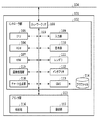
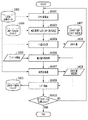
[カラープリンタ構成]
図1は本実施形態におけるカラープリンタ101を示す図である。すなわち、定着器後センサを搭載していない画像形成装置の例を示す図である。カラープリンタ101はコントローラ部102とプリンタ部103から構成されている。
[Color printer configuration]
FIG. 1 is a diagram showing a
コントローラ部102は図1に示すとおりCPU105などの各種モジュールがデータバス119を介して接続されて構成されている。RAM107はROM106に格納されているプログラムデータをロードし、一時記憶する。CPU105はRAM107にロードされたプログラムにしたがって各種モジュールに命令を出し、カラープリンタ101を動作させる。また、各モジュールが命令実行する際に生成されるデータなどもRAM107に一時記憶される。
As shown in FIG. 1, the
ネットワークI/F108は外部ネットワーク104とのインターフェイスモジュールである。例えばカラープリンタ101は、イーサネット(登録商標)などの通信プロトコルに基づきネットワーク104を介して他の機器から印刷データや後述する測定器情報の受信及び他の機器への測定チャート情報の送信といった双方向データ通信を行う。
The network I / F 108 is an interface module with the
インタプリタ112は受信した印刷データのPDL(Page Description Language:ページ記述言語)部分を解釈して中間言語データを生成する。そしてCMS(Color Management System)113はROM106に格納されているプロファイル114を用いて中間言語データの色変換を行い、CMS後中間言語データを生成する。CMS113では以下のように色変換を行っている。
The
プロファイル114は図示しないソースプロファイルとデスティネーションプロファイルから構成されている。ソースプロファイルとはRGBやCMYK等のPDLデータ入力機器デバイスに依存する色空間を、L*a*b*やXYZ等のデバイス非依存の色空間に変換するためのプロファイルである。XYZとはL*a*b*と同様にCIE(国際照明委員会)が制定したデバイス非依存の均等色空間の一つであり、3種類の刺激値で色を表現する。デスティネーションプロファイルとは、デバイス非依存の色空間を出力機器デバイス(本例の場合はカラープリンタ101)に依存したRGBもしくはCMYK色空間に変換するためのプロファイルである。ソースプロファイルとデスティネーションプロファイルでの色変換を実施することによって入力機器デバイスの色空間から出力機器デバイスの色空間へと変換するのである。
The
レンダラ111はCMS後中間言語データからラスター画像を生成する。画像処理部115は前記ラスター画像に対して画像処理を行う。
The
表示部110はユーザーへの指示やカラープリンタ101の状態を示すUI(User Interface:ユーザーインターフェイス)画面を表示するものである。入力部109はユーザーからの入力を受け付けるためのインターフェイスである。
The
チャート生成部118は後述する測定器情報を元に混色キャリブレーションに使用する用紙サイズを決定し、パッチデータ画像(チャート画像)を生成する機能を有している。チャート生成部118の詳細な動作については後述する。
The
コントローラ部102と接続されたプリンタ部103はC、M、Y、Kなどの有色トナーを用いて用紙上に画像データを形成するプリンタである。プリンタ部103は紙の給紙を行う給紙部116と印刷した用紙を排紙する排紙部117を持つ。
A
[測定プリンタ構成]
図2は本実施形態における測定プリンタ201を示す図である。すなわち、定着器後センサを搭載している画像形成装置の例を示す図である。測定プリンタ201はコントローラ部202とプリンタ部203から構成されている。
[Measurement printer configuration]
FIG. 2 is a diagram showing the
コントローラ部202は図2に示すとおりCPU205などの各種モジュールがデータバス219を介して接続されて構成されている。RAM207はROM206に格納されているプログラムデータをロードし、一時記憶する。CPU205はRAM207にロードされたプログラムにしたがって各種モジュールに命令を出し、測定プリンタ201を動作させる。また、各モジュールが命令実行する際に生成されるデータなどもRAM207に一時記憶される。
As shown in FIG. 2, the
ネットワークI/F208は外部ネットワーク104とのインターフェイスモジュールである。例えばイーサネット(登録商標)などの通信プロトコルに基づきネットワーク104を介して他の機器と、印刷データや後述する測定チャート情報の受信及び測定器情報の送信といった双方向データ通信を行う。
A network I / F 208 is an interface module with the
インタプリタ212は受信した印刷データのPDL部分を解釈して中間言語データを生成する。そしてCMS213はROM206に格納されているプロファイル214を用いて色変換を行い、CMS後中間言語データを生成する。CMS213では以下のように色変換を行っている。
The
プロファイル214は図示しないソースプロファイルとデスティネーションプロファイルから構成されている。ソースプロファイルとデスティネーションプロファイルでの色変換を実施することによって入力機器デバイスの色空間から出力機器デバイス(測定プリンタ201)の色空間へと変換するのである。
The
レンダラ211はCMS後中間言語データからラスター画像を生成する。画像処理部215は前記ラスター画像に対して画像処理を行う。
The
表示部210はユーザーへの指示や測定プリンタ201の状態を示すUI画面を表示するものである。入力部209はユーザーからの入力を受け付けるためのインターフェイスである。
The
スキャナ204はオートドキュメントフィーダーを含むスキャナである。スキャナ204は束状のあるいは一枚の原稿画像を図示しない光源で照射し、原稿反射像をレンズでCCD(Charge Coupled Device)センサ等の固体撮像素子上に結像する。そして、固体撮像素子からラスター状の画像読み取り信号を画像データとして得る。
The
プリンタ部203の図示しない紙搬送路上の定着器後にはL*a*b*やXYZ等のデバイスに依存しない色空間の値を取得できるセンサ220を持つ。プリンタ203で紙上に出力されたデータをセンサ220で読み取り、読み取った数値情報をコントローラ部202へ送信する。コントローラ部202の4D−LUT生成部218はセンサ220で読み取られた数値情報を用いて演算を行い、単色や混色の補正テーブルを生成する。なお、本実施形態では4D−LUTを生成する場合を説明するが、3D−LUTや1D−LUTを生成できるようにしてもよい。
The fixing unit on the paper conveyance path (not shown) of the
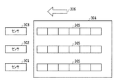
[センサの説明]
図3はセンサ301〜303を含むセンサ220の配置について測定プリンタ201の紙搬送路との関係も含めて説明する図である。センサは紙搬送路上に固定して配置する必要があるため、チャートの読み取りデータを増やす場合は紙の搬送方向306に向かって増やす必要がある。それだけでは1枚の紙で読み取れるデータ数が不十分となるため、さらにチャートの読み取りデータを増やす場合は紙の搬送方向306と垂直方向にセンサの個数を増やす必要がある。図3では3つのセンサを使用した例を示しており、チャート304上には、センサ301、センサ302、センサ303が固定されている位置に合わせてパッチデータ305を配置している。紙が搬送されてチャート304上の異なる色のパッチデータ305が各センサを通過する際に測定値を取得してプリンタ部203からコントローラ部202に送信する。
[Explanation of sensor]
FIG. 3 is a diagram illustrating the arrangement of the
[システム図]
図18はネットワーク104を介してカラープリンタ101と測定プリンタ201が接続されている図である。ここには情報処理装置であるPC1801も接続されており、PC1801上において、各プリンタに送信する印刷データを作成するプリンタドライバ1802が実行されている。各装置はネットワーク104を介して通信可能な状態となっている。また、ネットワーク104には図示する以外の多種のカラープリンタや測定プリンタ、PCが接続されているものとする。
[System diagram]
FIG. 18 is a diagram in which the
[測定チャートの説明]
図4はセンサ220が測定できるチャート304の各情報について説明する図である。本説明における単位は例えばミリメートル、インチなどの長さを示すものでも良いし、デジタル画像データの解像度における画素座標などでも良い。ただし、この場合は1画素あたりの大きさがわかるように物理解像度情報を付け加えておく必要がある。本説明では600dpi(dot per inch)の物理解像度における画素座標を元に説明する。
[Explanation of measurement chart]
FIG. 4 is a diagram illustrating each piece of information on the
紙の搬送方向306と垂直な方向を主走査方向、水平な方向を副走査方向とし、原点404を座標系の0pixとする。例えば、測定プリンタ201がプリント動作時に紙搬送路に通紙できるサイズがA3サイズである場合、その主走査方向のサイズは約297mmなので約7015pixとなり、副走査方向のサイズは約420mmなので約9921pixとなる。よって、パッチデータをチャート上に配置する場合、主走査方向の配置可能範囲の開始座標と終端座標はそれぞれXstart=0pix、Xend=7015pixとすることができる。
The direction perpendicular to the
そしてセンサ301、302、303が配置されている座標(すなわち、主走査方向の座標)をX1、X2、X3で表すことができる。本実施形態ではX1=700pix、X2=3500pix、X3=6300pixとする。
The coordinates at which the
各センサはパッチが配置されたチャートが通過する際に所定のサンプリング時間で測定を行う。これにより、センサの性能や測定プリンタの紙搬送速度に依存して、測定できるパッチ長さ403が決まる。また、パッチ幅402はセンサの主走査方向の開口サイズ、すなわちアパーチャーサイズよりも大きい必要がある。よって測定に十分なパッチ幅も、搭載しているセンサの性能により決定される。
Each sensor performs measurement at a predetermined sampling time when a chart on which patches are arranged passes. Accordingly, the
これらセンサが測定可能な範囲については、副走査方向の測定可能範囲座標をYstartと、Yendと、Yendからの余白量を示すY1とで表すことができる。センサ301〜303の測定位置にチャート304端部が搬送されてきてから実際に測定サンプリングするまでに搬送方向先端に余白を設ける場合がある。また、終端部も同様である。本実施形態ではYstart=100pix、Y1=100pix、Yend=9921pixとして説明する。また、測定可能パッチサイズ、すなわち、パッチ幅402は200pix、パッチ長403は600pixとして説明する。
Regarding the range that can be measured by these sensors, the measurable range coordinates in the sub-scanning direction can be represented by Ystart, Yend, and Y1 indicating the amount of margin from Yend. There is a case where a margin is provided at the front end in the transport direction after the end of the
これらXstart、Xend、Ystart、Yendで囲まれた部分が測定プリンタ201の測定可能範囲401を示している。
A portion surrounded by Xstart, Xend, Ystart, and Yend indicates a measurable range 401 of the
[画像処理部の説明]
図5はカラープリンタ101の画像処理部115を説明する図である。先述したとおり印刷データが入力されると、インタプリタ112、CMS113、レンダラ111での各処理後にラスター画像が画像処理部115に入力される。
[Description of Image Processing Unit]
FIG. 5 illustrates the
画像処理部115は少なくとも色変換部501、4D−LUT補正部502、1D−LUT補正部503、ハーフトーニング部504から構成されている。色変換部501はCMS113がデバイス依存のRGB色空間のデータを出力した際にRGB→CMYKに色空間変換するものである。CMS113がデバイス依存のCMYK色空間のデータを出力した際は本色変換部501がスキップされる。4D−LUT補正部502はCMYKの4次元の入力信号に対してC2、M2、Y2、K2の組み合わせの出力信号に変換する4D−LUTを用いて混色キャリブレーションを実施する。例えば4D−LUTが8×8×8×8の離散的な格子点で構成されている場合、その格子点数は4096個になる。データのbit深度が8bit(0〜255)で表現される場合は、格子点の間隔は約36となる。
The
この4D−LUTの入出力関係の例を示したのが図6である。図6は、各格子点の入力CMYK値に対して、それぞれ出力C2、M2、Y2、K2値が対応付けられているLUTである。実際に画像データのCMYK値が入力された場合は、入力値の周辺の4D−LUT格子点を複数選択し、選択された複数の出力信号から線形補間演算により、出力C2、M2、Y2、K2値が決定されるものである。 FIG. 6 shows an example of the input / output relationship of this 4D-LUT. FIG. 6 is an LUT in which the output C2, M2, Y2, and K2 values are associated with the input CMYK values of the respective grid points. When CMYK values of image data are actually input, a plurality of 4D-LUT lattice points around the input value are selected, and outputs C2, M2, Y2, K2 are obtained by linear interpolation operation from the selected output signals. The value is to be determined.
4D−LUT補正部502で混色の色を補正した後、1D−LUT補正部503にてC2、M2、Y2、K2の各単色の階調補正を行い、それぞれC3、M3、Y3、K3に変換する。例えば1D−LUTの入力信号が8bitデータである場合はLUTのエントリー数は0〜255の256個であることが好ましい。すなわち、全ての入力値に対してそれぞれ1個の出力値が格納されていることが好ましい。
After correcting the mixed color by the 4D-
図7(a)は4D−LUTの入出力関係の模式図を、図7(b)は1D−LUTの入出力関係の模式図を、それぞれ示すものである。4D−LUTの模式図 701によるとCMYKの組み合わせである混色の入力に対して、1種類の4D−LUTで、C2、M2、Y2、K2の混色された色の組み合わせが出力されていることがわかる。 FIG. 7A shows a schematic diagram of the input / output relationship of the 4D-LUT, and FIG. 7B shows a schematic diagram of the input / output relationship of the 1D-LUT. According to a schematic diagram 701 of 4D-LUT, a mixed color combination of C2, M2, Y2, and K2 is output by one type of 4D-LUT with respect to mixed color input that is a combination of CMYK. Recognize.
1D−LUTの模式図 702によると1つの入力に対して1つの出力がされていることがわかる。すなわち、C2入力C3出力用、M2入力M3出力用、Y2入力Y3出力用、K2入力K3出力用の4つの1D−LUTが独立しているのである。 According to the schematic diagram 702 of the 1D-LUT, it can be seen that one output is output for one input. That is, four 1D-LUTs for C2 input C3 output, M2 input M3 output, Y2 input Y3 output, and K2 input K3 output are independent.
最後にハーフトーニング部504でC3、M3、Y3、K3のデータが、ディザスクリーンなどの画像形成処理を施され、プリンタ103で用紙上に印刷される。
Finally, the data of C3, M3, Y3, and K3 is subjected to an image forming process such as a dither screen by the
測定プリンタ201の画像処理部215、レンダラ211、インタプリタ212、CMS213も上記カラープリンタ101と同様の動作をするので説明を省略する。
Since the
[カラープリンタ動作の説明]
前述したカラープリンタ101の動作について図8のフローチャートを用いて説明する。なお、本説明では表示部110はタッチパネル方式のLCD(Liquid Crystal Display)とし、入力部109の一部も担っているとする。入力部109は他にハードキーを有していてもよい。なお、以下で示すフローチャートは、カラープリンタ101のRAM107にロードされたプログラムをCPU105が実行することによって実行される。
[Description of color printer operation]
The operation of the
測定プリンタ201がネットワーク104を介して混色キャリブレーションのための通信ネゴシエーションをカラープリンタ101との間で行った後で、カラープリンタ101の動作が始まる。
After the
カラープリンタ101は、測定プリンタ201からネットワーク104を介して図9に示す測定器情報を取得してRAM107に格納する(ステップS801)。
The
この測定器情報には、例えばセンサ数、センサ位置座標、測定可能範囲、パッチ長さ、パッチ幅の情報が含まれている。また、前記センサ位置や測定可能範囲のそれぞれの単位、機体固有の番号についてなどの付帯情報が含まれてもよい。 This measuring instrument information includes, for example, information on the number of sensors, sensor position coordinates, measurable range, patch length, and patch width. Further, incidental information such as each unit of the sensor position and measurable range, and a number unique to the aircraft may be included.
次に、感光ドラム上もしくは1次転写ベルト上の、濃度を検出する図示しないセンサにて、C、M、Y、K各色の階調特性を測定し、1D−LUTを作成する(ステップS802)。1D−LUTの作成方法は公知の技術であるので詳細な説明を省略する。 Next, the gradation characteristics of each color of C, M, Y, and K are measured by a sensor (not shown) that detects the density on the photosensitive drum or the primary transfer belt, and a 1D-LUT is created (step S802). . Since a 1D-LUT creation method is a known technique, a detailed description thereof will be omitted.
チャート生成部118はステップS801で取得した測定器情報をRAM107からロードして、該測定器情報を元に混色キャリブレーションに使用するチャートの用紙サイズ、パッチデータの配置を算出して決定し、RAM107に格納する(ステップS803)。
The
図4のチャート304と図9の測定器情報を例に挙げてステップS803の動作を説明する。なお、図9に示す測定器情報は、図4のチャート304を説明した箇所にて例示した数値が含まれている。
The operation of step S803 will be described by taking the
チャート生成部118は、測定可能範囲を示す情報に基づいて印刷用紙サイズを算出して決定する。例えば、チャート生成部118は、XstartとXendの情報及び単位を示す情報から、測定プリンタの主走査方向の用紙最大幅が約297mmであることを算出することができる。また、YstartとYendの情報より測定プリンタの搬送方向に9921pixまでの用紙上に9821pixの位置までパッチデータを印刷できることを算出することができる。
The
まず主走査方向について説明する。図4よりセンサ301と303が測定できるパッチデータの端部距離は5800pixであることが算出できる。具体的には、まず、センサ位置X1=700pixとX3=6300との間隔が5600pixとなる。そして、さらにパッチ幅が200pixであり、それぞれセンサのアパーチャー中心から100pixずつ必要であるので、総計5800pix=約245mmと算出でき、これ以上の主走査方向長さかつ用紙最大幅約297mm以内の辺を持つ用紙が必要となる。例えばA系、B系の定型用紙であるとA3の短辺(約297mm)、A4の長辺(約297mm)、B4の短辺(約257mm)、B5の長辺(約257mm)がこの用紙に該当する。
First, the main scanning direction will be described. From FIG. 4, it can be calculated that the end distance of the patch data that can be measured by the
副走査方向についてはYstartとYendより算出される長さは、上記のA3、A4、B4、B5のどれもがその範囲内であることがわかる。最終的にA3、A4、B4、B5が用紙候補として決定される。カラープリンタ101に積載されている用紙のうち、前記用紙候補の中から一番副走査方向に長い用紙を選択することが好ましい。これは図4のチャート304の副走査方向になるべく多くのパッチデータを印刷したほうが混色キャリブレーションに使用する用紙の枚数を減らすことができるためである。
It can be seen that the lengths calculated from Ystart and Yend in the sub-scanning direction are all within the range of A3, A4, B4, and B5. Finally, A3, A4, B4, and B5 are determined as paper candidates. Of the sheets stacked on the
本実施形態ではカラープリンタ101には上記の用紙候補のうちA4が積載されている場合について説明を続ける。
In the present embodiment, the description will be continued with respect to the case where A4 is stacked among the above-mentioned paper candidates on the
A4用紙の長辺を図4のチャート304の主走査方向にすると副走査方向には約210mm=約4960pixの用紙領域がある。後端部にY1=100pixの余白が必要なので、すなわち用紙先端のYstartと後端のY1の余白を除くと4760pixのパッチデータ領域があることが算出される。
When the long side of A4 paper is set in the main scanning direction of the
図9の測定器情報よりパッチ長=600pixなので副走査方向には7パッチ配置することが可能であることが算出される。 From the measuring instrument information in FIG. 9, since the patch length is 600 pix, it is calculated that seven patches can be arranged in the sub-scanning direction.
以上より、A4用紙1枚には7パッチ×3センサ=21パッチ配置できることが算出される。例えば混色キャリブレーションに必要なパッチデータが100個だとするとA4用紙が5枚必要であることが導き出せるのである。 From the above, it is calculated that 7 patches × 3 sensors = 21 patches can be arranged on one A4 sheet. For example, if the patch data necessary for color mixture calibration is 100, it can be derived that five A4 sheets are necessary.
なお、混色キャリブレーションに必要なパッチデータ数はカラープリンタの機種によって異なってもよい。 Note that the number of patch data necessary for color mixture calibration may differ depending on the color printer model.
また、上記の例では、測定範囲可能サイズを包含する用紙サイズを用いる例を説明したが、測定範囲可能サイズよりも小さい用紙を用いても良い。用紙最大幅よりも小さい用紙を選択した場合であるが、主走査方向のセンター中心に用紙が搬送されるので、パッチデータを配置する際は選択した用紙幅と最大用紙幅の差分の1/2だけ座標系にオフセットをかければよい。 In the above example, the paper size including the measurement range possible size is described. However, a paper smaller than the measurement range possible size may be used. This is a case where a sheet smaller than the maximum sheet width is selected. However, since the sheet is conveyed to the center center in the main scanning direction, when arranging patch data, the difference between the selected sheet width and the maximum sheet width is ½. You only need to offset the coordinate system.
チャート生成部118はステップS803で導き出した印字用紙サイズとステップS801で取得したパッチサイズとROM106に格納されているパッチデータ値とを読みだす。そしてこれらを元に混色キャリブレーション用のチャート画像データを生成し、ページ毎にRAM107に格納する(ステップS804:チャート画像生成処理)。
The
CPU105はRAM107に格納されたキャリブレーション用のチャート画像データを呼び出し、画像処理部115に入力する。そして画像処理部115は図5の色変換部501と4D−LUT補正部502をスキップし、1D−LUT補正部503とハーフトーニング部504の処理を実行し、処理後のチャート画像データをプリンタ103にて印刷する。このとき1D−LUT補正部ではステップS802で生成したLUTを用いる(ステップS805)。
The
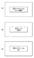
ステップS805での印刷動作中は、他の処理が実行されないように、表示部110には図11(a)のようにチャート印刷中の情報が表示されている。
During the printing operation in step S805, information during chart printing is displayed on the
ステップS805での印刷が終了したら、CPU105はステップS803で決定してRAMに格納されているチャートの用紙サイズを読み出す。またROM106に格納されている4D−LUT情報、補正ターゲット情報、CMY→L*a*bの3D−LUT、L*a*b*→CMYの3D−LUTを読み出す。CPU105は、これら読み出したデータなどを測定チャート情報としてネットワークI/F108、ネットワーク104を介して測定プリンタ201に送信する(ステップS806)。
When printing in step S805 ends, the
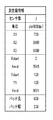
図10は測定チャート情報の一例を示している。この測定チャート情報には少なくともチャートの用紙サイズ、チャート枚数、1枚あたりのパッチデータ数、4D−LUTの格子点数、LUTデータのデータビット深度、各パッチデータに対する補正ターゲット色値、最大色材載り量が含まれている。 FIG. 10 shows an example of measurement chart information. This measurement chart information includes at least the paper size of the chart, the number of charts, the number of patch data per sheet, the number of 4D-LUT grid points, the data bit depth of the LUT data, the correction target color value for each patch data, the maximum color material placement The amount is included.
なお、パッチデータの数によっては端数が出てしまい、前記1枚あたりのパッチデータ数分だけ印刷しないページがある場合がある。この場合は該当するパッチデータに対して、例えば補正ターゲット色値をブランクにしておくか、ブランクであることを特定できる文字もしくは文字列を記載しておけばよい。 Depending on the number of patch data, fractions may appear, and there may be pages that are not printed by the number of patch data per sheet. In this case, for the corresponding patch data, for example, the correction target color value may be blank, or a character or a character string that can specify that it is blank may be described.
なお、複数の4D−LUTを1回の混色キャリブレーションで作成してもよく、その場合は測定チャート情報に少なくとも4D−LUT数とそれに対応する補正ターゲットデータを追記すればよい。複数の4D−LUTを作成する際は、測定チャート情報に記載の用紙の枚数とパッチ数により、作成される4D−LUTの数がわかる。 Note that a plurality of 4D-LUTs may be created by one color mixing calibration, and in that case, at least the number of 4D-LUTs and correction target data corresponding thereto may be added to the measurement chart information. When creating a plurality of 4D-LUTs, the number of 4D-LUTs to be created is known from the number of sheets and the number of patches described in the measurement chart information.
この後、CPU105は測定プリンタ201からの4D−LUT受信待ちをする(ステップS807)。このとき表示部110には図11(b)のように4D−LUT受信中である情報が表示されている。
Thereafter, the
このときステップS805で印刷されたチャートはユーザーによって測定プリンタ201まで搬送され、測定プリンタ201にて測定されている。
At this time, the chart printed in step S805 is conveyed to the
CPU105は測定プリンタ201から受信した4D−LUTをRAM107に格納し(ステップS808)、測定プリンタ201との通信を終了する(ステップS809)。このとき表示部110には図11(c)のように4D−LUTの受信が完了していることがわかる情報が表示されている。
The
以降、画像処理部115はRAM107に格納された4D−LUTを用いて、印刷時の画像処理を実施する。
Thereafter, the
[測定プリンタ動作の説明]
前述した測定プリンタ201の動作について図12のフローチャートを用いて説明する。なお、本説明では表示部210はタッチパネル方式のLCDとし、入力部209の一部も担っているとする。入力部209は他にハードキーを有していてもよい。
[Explanation of measurement printer operation]
The operation of the
測定プリンタ201の表示部210中の入力部209から図13(a)のような混色キャリブレーションの動作1310を選択すると、図13(b)のような他機種の混色キャリブレーション動作1320を選択できる画面に遷移する。図13(b)で他機種の混色キャリブレーション実行1321の入力があると図13(c)のようなカラープリンタ101を選択する画面に遷移する。
When a mixed
図13(c)では測定プリンタ201に予め登録されている、もしくは過去に他機種の混色キャリブレーションを実行したことがある、ネットワーク104を介して接続可能なカラープリンタの一覧が表示されている。ここでは各プリンタにつけられている固有な名称、例えばIPアドレスなどのカラープリンタを特定できるアドレス情報、その他カラープリンタの設置場所情報などが含まれている。
In FIG. 13C, a list of color printers that are registered in advance in the
図13(c)の画面上でユーザーがカラープリンタ101に相当する機種選択し、決定ボタン1330を押下してカラープリンタ101の混色キャリブレーションの実行を確定する(ステップS1201)。
On the screen of FIG. 13C, the user selects a model corresponding to the
CPU205はネットワークI/F208、ネットワーク104を介してステップS1201で選択したカラープリンタ101と通信を開始し、表示部210は図13(d)に示すようにチャートの印刷開始を入力するための印刷開始キー1340を表示する。印刷開始キー1340が押下されるとその命令をカラープリンタ101に送信する(ステップS1202)。
The
CPU205はROM206から図9で説明した測定器情報を読み出し、カラープリンタ101に送信する(ステップS1203:測定器情報送信処理)。
The
CPU205はカラープリンタ101から測定チャート情報を受信するよう待機する。測定チャート情報を受信したら、CPU205はRAM207に格納する(ステップS1204:測定チャート情報受信処理)。
The
そして表示部210は図13(e)に示すように給紙部216からチャート読み込みの入力待ち画面を表示し、CPU205はチャート読み込み待機をする(ステップS1205)。
Then, as shown in FIG. 13E, the
カラープリンタ101で印刷されたチャートがユーザーによって給紙部216に積載される。そしてステップS1205にて読み込み開始キー1350が押下されたら、CPU205はプリンタ部203の給紙部216から前記チャートを1枚ずつ給紙するようプリンタ部203を制御する。
The chart printed by the
そしてプリンタ部203は前記チャートを給紙し、印刷時に通紙する紙搬送路にて前記チャートを搬送する。このとき電子写真プロセスは全て無効になるよう設定しておく。前記チャートがセンサ220に到達するのと同期してチャート上に印刷されているパッチデータをセンサ220にて測定して色値を取得する。このときセンサ220はRAM207に格納されている測定チャート情報中の用紙サイズ情報、1枚あたりのパッチデータ数を元にパッチデータの測定を行う。このようにして測定された色値はRAM207に格納される。この動作はRAM207に格納されている測定チャート情報のチャート枚数情報の分だけ繰り返される。そして表示部210は図13(d)に示すように4D−LUT作成中の画面を表示する。ここで、複数枚のチャートを読み込む際に、プリンタ部203は電子写真プロセスの印刷枚数と同じ速度でチャートを給紙しても良いし、1枚ずつ測定が完了してから給紙しても良い(ステップS1206)。
The
ステップS1206で全てのチャートの読み込みと測定が終了したら、4D−LUT生成部218はRAM207に格納されている測定値と測定チャート情報とを読み出して補正テーブルである4D−LUTを生成する。そして生成した4D−LUTをRAM207に格納する(ステップS1207:補正テーブル生成処理)。すなわち、カラープリンタの色再現特性を補正するためのデータを生成するデータ生成処理を行う。なお4D−LUTの生成方法については後述する。
When reading and measurement of all charts are completed in step S1206, the 4D-
CPU205はRAM207からステップS1207で生成された4D−LUTを読み出し、ネットワークI/F208、ネットワーク104を介してカラープリンタ101に前記4D−LUTを送信する(ステップS1208:データ送信処理)。
The
CPU205は4D−LUTの送信が完了するとRAM207に格納されている測定チャート情報及び4D−LUTを削除してからカラープリンタ101との通信を終了し、表示部210は図13(e)に示す動作終了の画面を表示する(ステップS1209)。
When the transmission of the 4D-LUT is completed, the
[4D−LUTの作成方法]
次に図12のステップS1207での4D−LUTの作成方法について図14〜図16を用いて説明する。以下の処理はコントローラ部202のCPU205の指示により行う。
[Method for creating 4D-LUT]
Next, a method of creating a 4D-LUT in step S1207 in FIG. 12 will be described with reference to FIGS. The following processing is performed according to instructions from the
図14は4D−LUTを作成する処理の流れを示したものである。ステップS1401にてコントローラ部202はセンサ220に指示を出し、センサ220を用いてチャート304の測定を行い、L*a*b*値を得る。次にステップS1402にてコントローラ部202は測定したパッチデータを受け取り、有彩色と無彩色に分類して測色値1403を得てRAM207に格納する。ここでの分類方法はチャート304に予め有彩色か無彩色かの情報を付加してもよいし、パッチデータの数値あるいは測定したパッチデータを分析することによって判断してもよい。
FIG. 14 shows the flow of processing for creating a 4D-LUT. In step S1401, the
次にコントローラ部202はRAM207から測色値1403、補正ターゲット1405及びL*a*b*→CMYの3D−LUT1406を読み出す。補正ターゲット1405及びL*a*b*→CMYの3D−LUT1406は、測定チャート情報に含まれてカラープリンタ101から送られてきたものである。そして、ステップS1404にて3D−LUT補正処理を行い、L*a*b*→CMYの3D−LUT1407(補正後)を出力する。ステップS1404の3D−LUTの補正処理については後述する。補正ターゲット1405とは目標値となるL*a*b*値のことであり、有彩色と無彩色のそれぞれで定められている。L*a*b*→CMYの3D−LUT1406は既知の手法を用いて作成した色変換用のLUTであり、格子状に一定の間隔で定めたL*a*b*値に対応したデバイス固有のCMY値を記述したデータである。任意のL*a*b*値に対して補間演算を行い、CMY値を出力する。最後に、コントローラ部202はステップS1408にてCMY→L*a*b*の3D−LUT1409と、L*a*b*→CMYの3D−LUT(補正後)1407と、デバイス情報1410とを用いてCMYK→CMYKの4D−LUT1411を作成する。CMY→L*a*b*の3D−LUT1409及びデバイス情報1410は、測定チャート情報に含まれてカラープリンタ101から送られてきたものである。ステップS1408の4D−LUTの作成処理についても後述する。CMY→L*a*b*の3D−LUT1409は既知の手法を用いて作成した色変換用のLUTであり、格子状に一定の間隔で定めたCMY値に対応したL*a*b*値を記述したデータである。任意のCMY値に対して補間演算を行い、L*a*b*値を出力する。
Next, the
次にステップS1404で示す3D−LUT補正処理の詳細について、図15を用いて説明する。まず、ステップS1501にてコントローラ部202はRAM207から測色値1403と補正ターゲット1405を用いて有彩色のデータと無彩色のデータのそれぞれに対して差分データ1510を算出する。差分データ1510はパッチデータのデータの個数分算出され、有彩色と無彩色で分類されている。次にステップS1502にてコントローラ部202はRAM207からL*a*b*→CMYの3D−LUT1406を読み出し、格子点データ(L*a*b*)の1つを抽出し、有彩色か無彩色かを判定する。判定方法の例を説明する。a*及びb*の値は色相/彩度を示すデータであるため、両方のデータが0に近いものを無彩色として判定する。例えば閾値を定めるなど、ここでの判定方法はどのようなものでもよい。この判定したデータが格子点データ(L*a*b*及び有彩無彩情報)1503となる。ここで、L*a*b*のデータはL*が0〜100、a*とb*がそれぞれ−128〜128の範囲で、格子点の数が33×33×33の場合、L*が約3ずつ、a*とb*が8ずつ均等に増加したデータとなる。つまり、ここで抽出した格子点データは(L*、a*、b*)=(0、−128、−128)から、(L*、a*、b*)=(100、128、128)の範囲で構成された33×33×33=35937個のデータの1つとなる。さらに、有彩色であるか無彩色であるかの情報が付加されている。
Next, details of the 3D-LUT correction processing shown in step S1404 will be described with reference to FIG. First, in step S1501, the
次に、ステップS1504にてコントローラ部202は格子点データ(L*a*b*及び有彩無彩情報)1503と補正ターゲット1405との距離を算出する。そしてステップS1505にてコントローラ部202は距離が一定の閾値以内の差分データを抽出し、その差分データから格子点データ(L*a*b*及び有彩無彩情報)1503の補正量を決定する。その際に格子点データの有彩無彩情報を参照して、有彩色の時は有彩色の差分データを、無彩色の時は無彩色の差分データを用いて抽出処理を行う。ここで、抽出された差分データは複数個ある可能性があり、その中でも格子点データ(L*a*b*及び有彩無彩情報)1503に対して距離が近いデータ、遠いデータが存在する。距離が近い差分データの影響を強く、距離が遠い差分データの影響を弱くするため、差分データに対して計算した距離を使って重みつき加算を行い、格子点補正量を決定することができる。ここで、一定の閾値以内に差分データが存在しない場合の補正量は0とすることができる。
In step S1504, the
次にステップS1506にてコントローラ部202は格子点補正量を格子点データ(L*a*b*及び有彩無彩情報)1503に反映し、補正後格子点データ(L*a*b*)1507として格納する。そして、ステップ1508にてコントローラ部202は全ての格子点データに対して処理を行ったか判定を行い、処理を行っていない場合は新しい格子点データをステップS1502にて抽出して処理を繰り返す。全ての格子点を処理した場合はステップS1509にてコントローラ部102は補間演算処理を行う。全ての格子点データを処理している場合、格子点の数の分だけ補正後格子点データ(L*a*b*)1507が作成されている。このデータに対してL*a*b*→CMYの3D−LUT1406を使って補間演算を行って新しいCMY値を算出する。このCMY値を元々の格子点データに対する出力値として格納し、L*a*b*→CMYの3D−LUT(補正後)1407を作成する。以上のように格子点から一定の距離内にある差分データを参照して格子点の補正量を決定することで、少ないデータ数で多くの格子点データの補正量を決定することが可能となる。本実施形態の例に限らず、L*a*b*→CMYの3D−LUT1406を補正する手法であればどのようなものであってもよい。
In step S1506, the
次にステップS1408の4D−LUTを作成する処理について、図16を用いて説明する。まず、ステップS1401にてコントローラ部202はCMYK均等データ1602からCMY値を抽出する。ここでCMYK均等データの数は、CMYK→CMYKの4D−LUT1411の格子点と同じ数であり、データの間隔も同じである。例えばCMYK→CMYKの4D−LUT1411の格子点数が8×8×8×8=4096個の場合は、CMYK均等データ1602の数は4096個となる。データが8ビット(0〜255)で表現される場合は、データの間隔は約36となる。次にステップS1603にてコントローラ部202はCMY→L*a*b*の3D−LUT1409とL*a*b*→CMYの3D−LUT(補正後)1407とを用いて補間演算を行い、CMY値を決定する。まず、S1601で抽出されたCMY値からCMY→L*a*b*の3D−LUT1409を用いて補間演算を実行してL*a*b*値を求める。次に先ほど算出したL*a*b*値からL*a*b*→CMYの3D−LUT(補正後)1407を用いて補間演算を実行してCMY値を算出する。次に、ステップS1604にてコントローラ部202はCMYK均等データ1602のKの値を抽出し、先ほど決定されたCMY値を組み合わせてCMYK値1605を作成する。ここで抽出したK値はステップS1601にて抽出されたCMY値に対応するものである。そしてステップS1606にてコントローラ部202はデバイス情報1410を用いて載り量制限処理を行う。ここでデバイス情報1410とはカラープリンタ101が適用可能なトナー量を数値で表現したものであり、本実施形態では「載り量」と定義する。例えばCMYKの場合、単色の最大値を100%とすると最大で400%の信号値が設定できる。しかし、適用可能なトナーの総数が300%の場合の載り量は300%となる。
Next, the process of creating the 4D-LUT in step S1408 will be described with reference to FIG. First, in step S1401, the
CMYK値1605はその組み合わせによっては規定の載り量を超える可能性があるため、既知のUCR処理等を行って載り量制限処理を行う。ここで、UCR(Under Color Removable)処理とはCMYのトナーをKのトナーに置き換える処理のことである。一般に黒を表現する場合、CMYを等量用いて表現する手法とK単独で表現する手法が存在する。K単独で表現した場合、CMYで表現する場合に比べて濃度が低くなってしまうが載り量を少なくできるというメリットがある。そしてステップS1607にてコントローラ部202は純色化処理を行ってCMYK値(補正後)1608を作成する。CMYK→CMYKの4D−LUT1411で補正する際に、例えばC単色のデータはC単色で出力されることが理想である。それを実現するため、元となったCMYK均等データ1602を参照して、純色データであった場合CMYK値を純色データに修正する。例えばCMYK均等データ1602がC単色であるのにCMYK値(補正後)1608にMの値が入っている場合はMの値を0にする。そしてステップS1609にてコントローラ部202はCMYK値(補正後)1608をCMYK→CMYKの4D−LUT1411に格納する。最後にステップS1610にてコントローラ部202はCMYK均等データ1602を全て処理したかの判定を行い、全てのデータを処理していない場合は残りのCMYK均等データ1602からCMY値を抽出して処理を繰り返す。全てのデータをした場合は処理を終了し、CMYK→CMYKの4D−LUT1411が完成する。
Since the
ここで、LUTの格子点の数については、本実施形態の例に限らずどのようなものであってもよい。さらに、格子点数は例えばCMYK→CMYKの4D−LUT1411でCとMの格子点数が異なるなど、特殊な構成のLUTでもよい。
Here, the number of grid points of the LUT is not limited to the example of the present embodiment, and any number may be used. Furthermore, the number of grid points may be an LUT having a special configuration, for example, a CMYK →
[カラープリンタと測定プリンタの通信]
図17はこれまで説明してきたカラープリンタ101と測定プリンタ201との相互の通信ならびに動作を示した図である。カラープリンタ101と測定プリンタ201の各種動作は図8と図12の各ステップと対応付けて表記してある。
[Communication between color printer and measuring printer]
FIG. 17 is a diagram showing mutual communication and operation between the
以上説明した本実施形態により、定着器後センサを有する測定プリンタの定着器後センサの数や測定できるパッチデータ条件、用紙条件に対して、定着器後センサを有さないカラープリンタが柔軟に対応して測定チャートを印刷することが可能になる。また、カラープリンタが要求する4D−LUTなどの補正テーブルに対して、測定プリンタの4D−LUT生成部は柔軟に対応して4D−LUTを作成することができ、カラープリンタはこの4D−LUTを利用することが可能になる。よって、本実施形態で示した構成を搭載したカラープリンタや測定プリンタはお互いの機種を選ばずに混色キャリブレーションの効果を提供することが可能となる。 According to this embodiment described above, a color printer without a post-fixer sensor can flexibly respond to the number of post-fixer sensors of a measuring printer having a post-fixer sensor, patch data conditions that can be measured, and paper conditions. Thus, the measurement chart can be printed. Also, the 4D-LUT generation unit of the measurement printer can flexibly create a 4D-LUT for a correction table such as a 4D-LUT required by the color printer, and the color printer can create this 4D-LUT. It becomes possible to use. Therefore, a color printer or a measurement printer equipped with the configuration shown in the present embodiment can provide the effect of color mixture calibration without selecting a model of each other.
なお、本実施形態ではカラープリンタの補正に関して述べたが単色キャリブレーション機能を有していないモノクロプリンタの1D−LUTを作成するために測定プリンタを利用してもよい。この場合、補正ターゲット1405を濃度値にすればよい。また4D−LUT生成部218は単色キャリブレーションと同様の手法で1D−LUTを作成すればよい。
In this embodiment, the correction of the color printer has been described. However, a measurement printer may be used to create a 1D-LUT of a monochrome printer that does not have a monochrome calibration function. In this case, the
<実施形態2>
本実施形態ではカラープリンタ101から混色キャリブレーションの実行指示を発行し、測定プリンタ201を用いて混色キャリブレーションを実行する例を説明する。
<
In the present embodiment, an example in which an instruction to execute mixed color calibration is issued from the
カラープリンタ101の表示部110に用いるLCDが大型化してきている。これはユーザーに対して表示するコンテンツをリッチにできるので多くの情報をユーザーに提供することが可能となる。よって、複雑な動作指示も入力しやすくなるという利点がある。
LCDs used for the
図19は本実施形態におけるカラープリンタ101の動作の一例を示すフローチャートである。
FIG. 19 is a flowchart showing an example of the operation of the
カラープリンタ101の表示部110中の入力部109から図21(a)のような混色キャリブレーションの動作2101を選択すると、図21(b)のような測定プリンタ201を選択する画面に遷移する。図21(b)ではカラープリンタ101に予め登録されている、もしくは過去に混色キャリブレーションを実行したことがある、ネットワーク104を介して接続可能な測定プリンタの一覧が表示されている。この画面では各測定プリンタにつけられている固有な名称、例えばIPアドレスなどの測定プリンタを特定できるアドレス情報、その他測定プリンタの設置場所情報などが含まれている。
When the color
図21(b)に表示されている中から測定プリンタ201に相当する機種を選択し、図示しない入力部109の決定ボタンを押下してカラープリンタ101の混色キャリブレーションの実行を確定する(ステップS1901)。
A model corresponding to the
CPU105はネットワークI/F108、ネットワーク104を介してステップS1901で選択した測定プリンタ201と通信を開始する。表示部110は図21(c)に示すようにチャートの印刷開始を入力するための印刷開始キー2102を表示して入力待ち状態になる。また測定プリンタへ測定器情報を要求するコマンドを送信する(ステップS1902)。ステップS1902で印刷開始の入力があった場合、図8のステップS801へ移行する。
The
図20は本実施形態における測定プリンタ201の動作を示すフローチャートである。CPU205はカラープリンタ101と通信を開始したあと測定器情報の要求を待つ(ステップS2001)。ステップS2001で測定器情報の要求を受信した場合、図12のステップS1203へ移行する。
FIG. 20 is a flowchart showing the operation of the
図22は本実施形態におけるカラープリンタ101と測定プリンタ201との相互の通信ならびに動作を示した図である。カラープリンタ101と測定プリンタ201の各動作は図8、図12、図19及び図20の各ステップと対応付けて表記してある。
FIG. 22 is a diagram showing mutual communication and operation between the
なお、本実施形態においては、例えば過去に混色キャリブレーションを実行したことがある測定プリンタ201の測定器情報をカラープリンタ101においてRAM107に記憶しておいてもよい。この場合、測定プリンタ一覧から過去に混色キャリブレーションを実行したことがある測定プリンタ201を指定した場合には、記憶しておいた測定器情報を用いて上記の処理を行っても良い。すなわち、カラープリンタ101は、測定器情報を測定プリンタ201から受信することで取得してもよいし、RAM107から記憶しておいた測定器情報を取得してもよい。
In the present embodiment, for example, measuring device information of the measuring
以上説明した本実施形態により、カラープリンタ側から混色キャリブレーションの実行指示が行えるようになり、実施形態1と同様の効果を提供することが可能となる。混色キャリブレーションを実行したい機器上でこのような指示をすることが可能となるので、必要に応じてその場で直ちに補正実行指示を入力することが可能となる。 According to the present embodiment described above, it is possible to instruct execution of color mixture calibration from the color printer side, and it is possible to provide the same effects as those of the first embodiment. Since it is possible to give such an instruction on a device for which color mixture calibration is to be executed, it is possible to input a correction execution instruction immediately on the spot as necessary.
<実施形態3>
本実施形態では図18のPC1801上のプリンタドライバ1802から混色キャリブレーションの実行指示を発行し、カラープリンタ101と測定プリンタ201を用いて混色キャリブレーションを実行する例を説明する。
<
In the present embodiment, an example in which an instruction to execute mixed color calibration is issued from the
カラープリンタ101を使用するユーザーはPC1801からカラープリンタ101や測定プリンタ201に印刷指示を出していることもある。よって、PC1801からカラープリンタ101や測定プリンタ201に混色キャリブレーションの実行を指示することもユーザビリティの観点で有効である。
A user who uses the
図23は本実施形態におけるプリンタドライバ1802の動作を示すフローチャートである。
FIG. 23 is a flowchart showing the operation of the
PC1801の図示しないディスプレイ画面上に図24(a)のようなプリンタドライバ画面2401が表示されている。このプリンタドライバ画面中の混色キャリブレーション動作2402を選択すると、図24(b)のような測定プリンタ201を選択する画面に遷移する。図24(b)では予め登録されている、もしくは過去にプリンタドライバ1802が制御するカラープリンタ101の混色キャリブレーションを実行したことがある、ネットワーク104を介して接続可能な即定プリンタの一覧が表示されている。この画面では各測定プリンタにつけられている固有な名称、例えばIPアドレスなどの測定プリンタを特定できるアドレス情報、その他測定プリンタの設置場所情報などが含まれている。
A
図24(b)の画面上で測定プリンタ201に相当する機種を選択し、決定ボタン2403を押下してカラープリンタ101の混色キャリブレーションの実行を確定する(ステップS2301)。
A model corresponding to the
次にPC1801上のプリンタドライバ1802は図24(c)に示すようにチャートの印刷開始を入力するための印刷開始キー2404を表示して入力待ち状態になる(ステップS2302)。
Next, as shown in FIG. 24C, the
ステップS2302で印刷開始の入力があると、プリンタドライバ1802はカラープリンタ101に混色キャリブレーションに用いるチャートの印刷指示を送信し、終了する。
When there is an input for starting printing in step S2302, the
プリンタドライバ1802からのチャート印刷指示を受信したカラープリンタ101のCPU105は図19のステップS1902からの動作を実行する。また測定プリンタ201は図20のステップS2001からの動作を実行する。
The
図25は前述した本実施形態におけるPC1801上のプリンタドライバ1802とカラープリンタ101と測定プリンタ201の相互の通信ならびに動作を示した図である。それぞれの動作は図8、図12、図19、図20及び図23の各ステップと対応付けて表記してある。
FIG. 25 is a diagram showing communication and operation among the
以上説明した本実施形態により、プリンタドライバ1802から混色キャリブレーションの実行指示が行えるようになり、実施形態1ならびに実施形態2と同様の効果を提供することが可能となる。
According to the present embodiment described above, it is possible to instruct execution of color mixture calibration from the
<実施形態4>
これまで説明した実施形態においては、図12のステップS1205では測定チャートが積載されて、チャート読み込みが待機されている状態が続く。このときに測定プリンタを他のユーザーが操作できない状態になってしまう。すなわちカラープリンタ101の混色キャリブレーション動作が測定プリンタ201を占有してしまうのである。このようなときでも測定プリンタ201が即座に使用できるようにするとともに、混色キャリブレーションにも即座に復帰できる実施形態を説明する。
<Embodiment 4>
In the embodiment described so far, in step S1205 of FIG. 12, the measurement chart is loaded and the state where the chart reading is on standby continues. At this time, the measurement printer cannot be operated by other users. That is, the color mixing calibration operation of the
測定プリンタは基本的には図12のフローチャートに従って動作している。図26は図12のステップS1204とステップS1206の間のステップについて説明している。すなわちステップS1205を図26のフローチャートで置き換えるのである。 The measurement printer basically operates according to the flowchart of FIG. FIG. 26 describes steps between step S1204 and step S1206 of FIG. That is, step S1205 is replaced with the flowchart of FIG.
表示部210は図27(a)に示すように給紙部216からチャート読み込みの入力画面を表示し、CPU205はチャート読み込みを待機する(ステップS2601)。
As shown in FIG. 27A, the
CPU205はチャート読み込みを待機しつつ図27(a)の一時中止キー2701が押下されるか否かも監視する(S3802)。すなわち、ユーザーから、センサを用いた測定の中断指示入力を受け付けたか否かを監視する。ステップS2601及びステップS2602で入力がない限り、CPU205は両ステップを繰り返す。
The
ステップS2602で図27(a)の一時中止キー2701が押下された場合は、表示部210は図27(b)に示すように混色キャリブレーション再開キー2702を伴う通常画面を表示する。ここで通常画面とは測定プリンタ201のトップ画面を含む、混色キャリブレーション以外の動作時に表示する画面を指す(ステップS2603)。
When the temporary stop key 2701 in FIG. 27A is pressed in step S2602, the
CPU205は通常の動作を制御しながら、混色キャリブレーション再開キー2702が押下されるまで待機し、押下された場合はステップS2601に戻る(ステップS2604)。すなわち、ユーザーから、中断した処理の再開指示入力を受け付けた場合には、ステップS2601に戻る処理が行われる。
The
以上説明した本実施形態により測定プリンタ201を混色キャリブレーションだけに占有することなく、実施形態1〜3で説明した各動作を提供することが可能になる。
According to the present embodiment described above, each operation described in the first to third embodiments can be provided without occupying the
<実施形態5>
図28は本実施形態で説明するカラープリンタ101の構成を示している。ここでカラープリンタ101は4D−LUT生成部2801を有している。
<
FIG. 28 shows the configuration of the
CPU105は前述した測定プリンタ201で測定した測定データを、ネットワーク104を介して受信し、RAM107に格納する。4D−LUT生成部2801は4D−LUT生成部218と同様の動作によりカラープリンタ101の混色を補正する4D−LUTを生成する。
The
なお、この場合、測定チャート情報には少なくとも図10に示す項目のうちチャート枚数、用紙サイズ、1枚あたりの用紙数の情報が含まれていればよい。 In this case, the measurement chart information may include at least information on the number of charts, the sheet size, and the number of sheets per sheet among the items shown in FIG.
以上説明した本実施形態により測定プリンタ201の4D−LUT生成部218の演算リソースを使わずにプリンタ101の混色を補正する4D−LUTを生成することが可能になる。
According to the present embodiment described above, it is possible to generate a 4D-LUT that corrects the color mixture of the
<その他の実施形態>
以上説明した各実施形態においては、測定を行う画像形成装置が定着器後センサを有する画像形成装置である例を用いて説明した。定着器後センサを使用することで、定着までに生じ得る環境変動の影響を少なくすることができる。しかしながら、感光ドラム上もしくは1次転写ベルト上に濃度を検出するセンサを有する画像形成装置が測定を行っても良い。すなわち、任意の種類のセンサを有する画像形成装置においても上記の各実施形態の処理を適用することが可能である。この場合、例えば測定プリンタ201からの測定器情報として、センサの種類を識別する情報を含めることによって、どの種類のセンサを利用できるかをカラープリンタ101にて把握することができる。また、例えば測定プリンタ201に複数の利用可能な種類のセンサが搭載されている場合には、どの種類のセンサでの測定を要求するかを示す情報がカラープリンタ101からの測定チャート情報に含めることも可能である。
<Other embodiments>
In each of the embodiments described above, the description has been given using an example in which the image forming apparatus that performs measurement is an image forming apparatus having a post-fixer sensor. By using the post-fixer sensor, it is possible to reduce the influence of environmental fluctuations that may occur before fixing. However, the image forming apparatus having a sensor for detecting the density on the photosensitive drum or the primary transfer belt may perform the measurement. That is, the processing of each of the above embodiments can be applied to an image forming apparatus having any type of sensor. In this case, for example, by including information for identifying the type of sensor as measuring instrument information from the measuring
また、本発明は、以下の処理を実行することによっても実現される。即ち、上述した実施形態の機能を実現するソフトウェア(プログラム)を、ネットワーク又は各種記憶媒体を介してシステム或いは装置に供給し、そのシステム或いは装置のコンピュータ(またはCPUやMPU等)がプログラムを読み出して実行する処理である。 The present invention can also be realized by executing the following processing. That is, software (program) that realizes the functions of the above-described embodiments is supplied to a system or apparatus via a network or various storage media, and a computer (or CPU, MPU, or the like) of the system or apparatus reads the program. It is a process to be executed.
Claims (16)
前記第2の画像形成装置における測定器を構成するセンサの数に関する情報と、前記測定器におけるセンサの配置位置に関する情報と、測定対象のチャート画像において前記測定器が測定可能な範囲に関する情報と、前記測定器が測定可能な前記チャート画像上のパッチサイズに関する情報を含む測定器情報を取得する取得手段と、
前記取得手段にて取得した測定器情報を用いてチャート画像を生成するチャート画像生成手段と、
前記チャート画像生成手段にて生成されたチャート画像を測定するための条件を含む測定チャート情報を前記第2の画像形成装置に送信する送信手段と、
前記送信手段によって送信された測定チャート情報を用いて前記第2の画像形成装置にて前記チャート画像の測定結果から取得されるデータであり、前記第2の画像形成装置から送信される、色再現特性を補正するためのデータを受信する受信手段と、
前記受信手段にて受信したデータを用いて画像を形成する画像形成手段と
を備えることを特徴とする第1の画像形成装置。 A first image forming apparatus capable of communicating with a second image forming apparatus having a measuring instrument having at least one sensor for measuring color,
Information relating to the number of sensors constituting the measuring instrument in the second image forming apparatus, information relating to the arrangement position of the sensor in the measuring instrument, information relating to a range that can be measured by the measuring instrument in the chart image to be measured, Obtaining means for obtaining measuring instrument information including information on a patch size on the chart image that can be measured by the measuring instrument;
Chart image generation means for generating a chart image using the measuring instrument information acquired by the acquisition means;
Transmitting means for transmitting measurement chart information including conditions for measuring the chart image generated by the chart image generating means to the second image forming apparatus;
Color reproduction, which is data acquired from the measurement result of the chart image in the second image forming apparatus using the measurement chart information transmitted by the transmitting unit, and transmitted from the second image forming apparatus Receiving means for receiving data for correcting the characteristics;
An image forming means for forming an image using data received by the receiving means.
前記受信手段にて受信した測定データを用いて色再現特性を補正する補正テーブルを生成する補正テーブル生成手段をさらに備え、
前記第1の画像形成装置は、前記補正テーブル生成手段にて生成した補正テーブルを用いて画像を形成することを特徴とする請求項1に記載の第1の画像形成装置。 The receiving means receives measurement data measured using the measurement chart information as the data,
A correction table generating means for generating a correction table for correcting the color reproduction characteristics using the measurement data received by the receiving means;
The first image forming apparatus according to claim 1, wherein the first image forming apparatus forms an image using a correction table generated by the correction table generating unit.
前記補正実行指示の入力に応じて前記第2の画像形成装置に測定器情報を要求する要求手段とをさらに備え、
前記取得手段は、前記要求手段による要求に対して前記第2の画像形成装置から送信された測定器情報を取得することを特徴とする請求項1に記載の第1の画像形成装置。 An input means for receiving an input of a correction execution instruction;
Requesting means for requesting measuring instrument information from the second image forming apparatus in response to an input of the correction execution instruction;
2. The first image forming apparatus according to claim 1, wherein the obtaining unit obtains measuring device information transmitted from the second image forming apparatus in response to a request from the request unit.
前記測定器を構成するセンサの数に関する情報と、前記測定器におけるセンサの配置位置に関する情報と、測定対象のチャート画像において前記測定器が測定可能な範囲に関する情報と、前記測定器が測定可能な前記チャート画像上のパッチサイズに関するパッチサイズに関する情報を含む測定器情報を前記1の画像形成装置に送信する測定器情報送信手段と、
前記測定器情報を用いて前記第1の画像形成装置で生成されたチャート画像を測定するための条件を含む測定チャート情報を前記第1の画像形成装置から受信する測定チャート情報受信手段と、
前記第1の画像形成装置で生成されたチャート画像を、前記センサを有する測定器と前記測定チャート情報受信手段にて受信した前記測定チャート情報とを用いて測定して前記第1の画像形成装置の色再現特性を補正するためのデータを生成するデータ生成手段と、
前記データ生成手段にて生成したデータを前記第1の画像形成装置に送信するデータ送信手段と
を備えることを特徴とする第2の画像形成装置。 A second image forming apparatus having a measuring instrument having at least one sensor for measuring color, which can communicate with the first image forming apparatus,
Information relating to the number of sensors constituting the measuring device, information relating to the arrangement position of the sensor in the measuring device, information relating to a range that can be measured by the measuring device in a chart image to be measured, and measurement possible by the measuring device Measuring instrument information transmitting means for transmitting measuring instrument information including information relating to the patch size relating to the patch size on the chart image to the one image forming apparatus;
Measurement chart information receiving means for receiving, from the first image forming apparatus, measurement chart information including conditions for measuring the chart image generated by the first image forming apparatus using the measuring device information;
The first image forming apparatus which measures the chart image generated by the first image forming apparatus using the measuring instrument having the sensor and the measurement chart information received by the measurement chart information receiving means. Data generating means for generating data for correcting the color reproduction characteristics of
A second image forming apparatus comprising: a data transmission unit configured to transmit data generated by the data generation unit to the first image forming apparatus.
前記測定器情報送信手段は、前記補正実行指示の入力を受けると前記第1の画像形成装置に測定器情報を送信することを特徴とする請求項7に記載の第2の画像形成装置。 An input unit that receives an input of a correction execution instruction;
8. The second image forming apparatus according to claim 7, wherein the measuring instrument information transmitting unit transmits the measuring instrument information to the first image forming apparatus when receiving the correction execution instruction.
前記中断指示入力手段により前記センサを有する測定器を用いた測定の中断指示が入力され、前記センサを有する測定器を用いた測定が中断されている場合、前記中断された前記センサを有する測定器を用いた測定の再開指示の入力を受け付ける再開指示入力手段と
をさらに備えることを特徴とする請求項7に記載の第2の画像形成装置。 Interruption instruction input means for accepting an input of an instruction to interrupt measurement using a measuring instrument having the sensor,
The interrupt instruction interruption instruction input measurement using a measuring instrument having a sensor by means are input, if the measurement using a measuring instrument having the sensor is interrupted, the instrument having a sensor that the interrupted 8. The second image forming apparatus according to claim 7, further comprising a restart instruction input unit that receives an input of a measurement restart instruction using .
前記第2の画像形成装置における測定器を構成するセンサの数に関する情報と、前記測定器におけるセンサの配置位置に関する情報と、測定対象のチャート画像において前記測定器が測定可能な範囲に関する情報と、前記測定器が測定可能な前記チャート画像上のパッチサイズに関する情報を含む測定器情報を取得する取得ステップと、
前記取得ステップにて取得した測定器情報を用いてチャート画像を生成するチャート画像生成ステップと、
前記チャート画像生成ステップにて生成されたチャート画像を測定するための条件を含む測定チャート情報を前記第2の画像形成装置に送信する送信ステップと、
前記送信ステップによって送信された測定チャート情報を用いて前記第2の画像形成装置にて前記チャート画像の測定結果から取得されるデータであり、前記第2の画像形成装置から送信される、色再現特性を補正するためのデータを受信する受信ステップと、
前記受信ステップにて受信したデータを用いて画像を形成する画像形成ステップとを備えることを特徴とする第1の画像形成装置の制御方法。 A control method of a first image forming apparatus capable of communicating with a second image forming apparatus having a measuring device having at least one sensor for measuring color,
Information relating to the number of sensors constituting the measuring instrument in the second image forming apparatus, information relating to the arrangement position of the sensor in the measuring instrument, information relating to a range that can be measured by the measuring instrument in the chart image to be measured, An acquisition step of acquiring measuring device information including information on a patch size on the chart image that can be measured by the measuring device;
A chart image generation step for generating a chart image using the measuring instrument information acquired in the acquisition step;
A transmission step of transmitting measurement chart information including conditions for measuring the chart image generated in the chart image generation step to the second image forming apparatus;
Color reproduction, which is data acquired from the measurement result of the chart image in the second image forming apparatus using the measurement chart information transmitted in the transmitting step, and transmitted from the second image forming apparatus A receiving step for receiving data for correcting the characteristics;
And an image forming step of forming an image using the data received in the receiving step.
前記測定器を構成するセンサの数に関する情報と、前記測定器におけるセンサの配置位置に関する情報と、測定対象のチャート画像において前記測定器が測定可能な範囲に関する情報と、前記測定器が測定可能な前記チャート画像上のパッチサイズに関するパッチサイズに関する情報を含む測定器情報を前記1の画像形成装置に送信する測定器情報送信ステップと、
前記測定器情報を用いて前記第1の画像形成装置で生成されたチャート画像を測定するための条件を含む測定チャート情報を前記第1の画像形成装置から受信する測定チャート情報受信ステップと、
前記第1の画像形成装置で生成されたチャート画像を、前記センサを有する測定器と前記測定チャート情報受信ステップにて受信した前記測定チャート情報とを用いて測定して前記第1の画像形成装置の色再現特性を補正するためのデータを生成するデータ生成ステップと、
前記データ生成ステップにて生成したデータを前記第1の画像形成装置に送信するデータ送信ステップと
を備えることを特徴とする第2の画像形成装置の制御方法。 A control method for a second image forming apparatus having a measuring instrument having at least one sensor for measuring color, which can communicate with the first image forming apparatus,
Information relating to the number of sensors constituting the measuring device, information relating to the arrangement position of the sensor in the measuring device, information relating to a range that can be measured by the measuring device in a chart image to be measured, and measurement possible by the measuring device Measuring instrument information transmitting step for transmitting measuring instrument information including information relating to the patch size relating to the patch size on the chart image to the one image forming apparatus;
A measurement chart information receiving step for receiving, from the first image forming apparatus, measurement chart information including a condition for measuring a chart image generated by the first image forming apparatus using the measuring device information;
The first image forming apparatus is configured to measure a chart image generated by the first image forming apparatus using the measuring instrument having the sensor and the measurement chart information received in the measurement chart information receiving step. A data generation step for generating data for correcting the color reproduction characteristics of
And a data transmission step of transmitting the data generated in the data generation step to the first image forming apparatus.
Priority Applications (2)
| Application Number | Priority Date | Filing Date | Title |
|---|---|---|---|
| JP2011142868A JP5751952B2 (en) | 2011-06-28 | 2011-06-28 | Image forming apparatus and image forming apparatus control method |
| US13/517,867 US8964221B2 (en) | 2011-06-28 | 2012-06-14 | Image forming apparatus and control method for the image forming apparatus |
Applications Claiming Priority (1)
| Application Number | Priority Date | Filing Date | Title |
|---|---|---|---|
| JP2011142868A JP5751952B2 (en) | 2011-06-28 | 2011-06-28 | Image forming apparatus and image forming apparatus control method |
Publications (3)
| Publication Number | Publication Date |
|---|---|
| JP2013012828A JP2013012828A (en) | 2013-01-17 |
| JP2013012828A5 JP2013012828A5 (en) | 2014-08-14 |
| JP5751952B2 true JP5751952B2 (en) | 2015-07-22 |
Family
ID=47390372
Family Applications (1)
| Application Number | Title | Priority Date | Filing Date |
|---|---|---|---|
| JP2011142868A Expired - Fee Related JP5751952B2 (en) | 2011-06-28 | 2011-06-28 | Image forming apparatus and image forming apparatus control method |
Country Status (2)
| Country | Link |
|---|---|
| US (1) | US8964221B2 (en) |
| JP (1) | JP5751952B2 (en) |
Families Citing this family (17)
| Publication number | Priority date | Publication date | Assignee | Title |
|---|---|---|---|---|
| JP2013198055A (en) * | 2012-03-22 | 2013-09-30 | Ricoh Co Ltd | Image reader and image reader control method |
| JP2014033306A (en) * | 2012-08-02 | 2014-02-20 | Canon Inc | Image processing apparatus, and image forming method and program |
| JP5990093B2 (en) * | 2012-11-29 | 2016-09-07 | キヤノン株式会社 | Image processing apparatus, image processing method, and program |
| US10397446B2 (en) * | 2015-03-31 | 2019-08-27 | Hewlett-Packard Development Company, L.P. | Correcting color differences between scanner modules |
| US9917985B2 (en) * | 2016-04-29 | 2018-03-13 | Konica Minolta Laboratory U.S.A., Inc. | Method and system for checking color among a printer having an in-line sensor and printers without an in-line sensor |
| JP6924001B2 (en) | 2016-07-07 | 2021-08-25 | キヤノン株式会社 | Printing system, printing device and its control method and program |
| JP2018023031A (en) | 2016-08-04 | 2018-02-08 | 株式会社リコー | Image forming apparatus, method, and program |
| US10893172B2 (en) * | 2016-10-24 | 2021-01-12 | Hewlett-Packard Development Company, L.P. | Color calibration |
| US10152738B2 (en) * | 2016-12-22 | 2018-12-11 | Capital One Services, Llc | Systems and methods for providing an interactive virtual environment |
| JP7023611B2 (en) | 2017-04-10 | 2022-02-22 | キヤノン株式会社 | Image forming device |
| JP7285824B2 (en) * | 2017-08-09 | 2023-06-02 | ファゾム・オプティクス・インコーポレイテッド | Manufacture of light field prints |
| JP2019197300A (en) * | 2018-05-08 | 2019-11-14 | コニカミノルタ株式会社 | Image analysis processing system, management device, image processing device, and program |
| JP7182931B2 (en) * | 2018-07-25 | 2022-12-05 | キヤノン株式会社 | PRINTING SYSTEM, PRINTING METHOD, IMAGE PROCESSING APPARATUS, AND IMAGE PROCESSING METHOD |
| KR20200026386A (en) * | 2018-08-30 | 2020-03-11 | 휴렛-팩커드 디벨롭먼트 컴퍼니, 엘.피. | Method for outputting color image in user color |
| JP2020170115A (en) * | 2019-04-04 | 2020-10-15 | コニカミノルタ株式会社 | Image forming system, control method for image forming system, control program for image forming system |
| WO2021010978A1 (en) * | 2019-07-15 | 2021-01-21 | Hewlett-Packard Development Company, L.P. | Color prediction |
| JP7554790B2 (en) * | 2022-04-26 | 2024-09-20 | キヤノン株式会社 | Color management system, information processing device, control method thereof, and program |
Family Cites Families (16)
| Publication number | Priority date | Publication date | Assignee | Title |
|---|---|---|---|---|
| JP3165724B2 (en) | 1992-02-14 | 2001-05-14 | キヤノン株式会社 | Communication device |
| JPH08293980A (en) | 1995-04-25 | 1996-11-05 | Canon Inc | Facsimile equipment |
| US6047288A (en) | 1995-07-20 | 2000-04-04 | Canon Kabushiki Kaisha | Group environment setting method and system thereof to provide an equivalent environment for plural participants |
| US6286034B1 (en) | 1995-08-25 | 2001-09-04 | Canon Kabushiki Kaisha | Communication apparatus, a communication system and a communication method |
| US6043909A (en) * | 1996-02-26 | 2000-03-28 | Imagicolor Corporation | System for distributing and controlling color reproduction at multiple sites |
| EP1080892B2 (en) * | 1999-09-06 | 2009-06-24 | Komori Corporation | Color management method and apparatus for printing press |
| JP2002199237A (en) * | 2000-12-27 | 2002-07-12 | Seiren Co Ltd | Color reproducing method for record |
| JP4860854B2 (en) | 2001-09-28 | 2012-01-25 | キヤノン株式会社 | Color image forming system |
| ATE459865T1 (en) * | 2004-05-05 | 2010-03-15 | X Rite Inc | SPECTROPHOTOMETER WITH AUTO-TRACKING |
| JP2006165864A (en) | 2004-12-06 | 2006-06-22 | Canon Inc | Color image processing system |
| JP4714660B2 (en) * | 2006-10-18 | 2011-06-29 | セイコーエプソン株式会社 | Printing device control system, printing device control method, and printing device control program |
| JP4269182B2 (en) * | 2006-10-18 | 2009-05-27 | セイコーエプソン株式会社 | Printing color measurement control device, printing color measurement control method, printing color measurement control program, and printing apparatus |
| JP5017072B2 (en) | 2007-12-13 | 2012-09-05 | キヤノン株式会社 | Image processing apparatus, control method thereof, and program |
| JP5475402B2 (en) * | 2008-12-22 | 2014-04-16 | キヤノン株式会社 | Image processing apparatus, image processing method, and program |
| JP2011023991A (en) * | 2009-07-16 | 2011-02-03 | Konica Minolta Business Technologies Inc | Information processor and program |
| US8599435B2 (en) * | 2009-11-12 | 2013-12-03 | Xerox Corporation | Photoreceptor motion quality estimation using multiple sampling intervals |
-
2011
- 2011-06-28 JP JP2011142868A patent/JP5751952B2/en not_active Expired - Fee Related
-
2012
- 2012-06-14 US US13/517,867 patent/US8964221B2/en not_active Expired - Fee Related
Also Published As
| Publication number | Publication date |
|---|---|
| US20130003090A1 (en) | 2013-01-03 |
| JP2013012828A (en) | 2013-01-17 |
| US8964221B2 (en) | 2015-02-24 |
Similar Documents
| Publication | Publication Date | Title |
|---|---|---|
| JP5751952B2 (en) | Image forming apparatus and image forming apparatus control method | |
| JP6193589B2 (en) | Image processing apparatus, image processing method, and program for executing image processing method | |
| JP5990093B2 (en) | Image processing apparatus, image processing method, and program | |
| US8358944B2 (en) | Image forming apparatus and method for print control | |
| JP5838999B2 (en) | Image forming method, image forming system, image forming apparatus, controller, printer, color correction apparatus, program for these apparatuses, and computer-readable recording medium recording these apparatus programs | |
| US9225878B2 (en) | Image processing apparatus, image processing method, and program | |
| JP2011082686A (en) | Image processor, image forming system, and program | |
| US20130135632A1 (en) | Image processing apparatus, controlling method of image processing apparatus, and storage medium | |
| JP5959954B2 (en) | Information processing apparatus, information processing method, and program thereof | |
| JP2014007647A (en) | Image processing apparatus, image processing method, and program therefor | |
| US9100624B2 (en) | Information processing apparatus, method and medium for generating color correction data with reference to measured color values from a number of sensors | |
| US20110158663A1 (en) | Printing apparatus, printing method, printing system, and program for implementing the printing method | |
| JP2018082360A (en) | Image processing apparatus, image processing method, and program for creating image processing parameter | |
| US20070024920A1 (en) | Image processing device, image formation device, and image processing method | |
| JP5896710B2 (en) | Image forming apparatus, image forming apparatus control method, and program | |
| JP2014099830A (en) | Color image processing apparatus and image processing method, and program for performing image processing method | |
| US7548342B2 (en) | Image processing apparatus | |
| JP5126693B2 (en) | Image forming apparatus and printing control method | |
| JP6239080B2 (en) | Image forming apparatus, control method therefor, and computer program | |
| JP6041633B2 (en) | Color image processing apparatus, control method therefor, and program for executing image processing method | |
| JP2011254473A (en) | Image processing system, method for the same, and image forming device | |
| JP5593888B2 (en) | Image processing apparatus, image forming apparatus, and program | |
| JP2017225193A (en) | Imaging apparatus, and its control method and computer program | |
| JP2013186375A (en) | Image forming apparatus and image processing method | |
| US20130063466A1 (en) | System and method to enable correction of text handling mismatches via segmentation |
Legal Events
| Date | Code | Title | Description |
|---|---|---|---|
| A521 | Request for written amendment filed |
Free format text: JAPANESE INTERMEDIATE CODE: A523 Effective date: 20140627 |
|
| A621 | Written request for application examination |
Free format text: JAPANESE INTERMEDIATE CODE: A621 Effective date: 20140627 |
|
| A131 | Notification of reasons for refusal |
Free format text: JAPANESE INTERMEDIATE CODE: A131 Effective date: 20150210 |
|
| A521 | Request for written amendment filed |
Free format text: JAPANESE INTERMEDIATE CODE: A523 Effective date: 20150220 |
|
| TRDD | Decision of grant or rejection written | ||
| A01 | Written decision to grant a patent or to grant a registration (utility model) |
Free format text: JAPANESE INTERMEDIATE CODE: A01 Effective date: 20150421 |
|
| A61 | First payment of annual fees (during grant procedure) |
Free format text: JAPANESE INTERMEDIATE CODE: A61 Effective date: 20150519 |
|
| R151 | Written notification of patent or utility model registration |
Ref document number: 5751952 Country of ref document: JP Free format text: JAPANESE INTERMEDIATE CODE: R151 |
|
| LAPS | Cancellation because of no payment of annual fees |