JP6815837B2 - Printing system, image processing equipment, calibration control method, and program - Google Patents
Printing system, image processing equipment, calibration control method, and program Download PDFInfo
- Publication number
- JP6815837B2 JP6815837B2 JP2016218972A JP2016218972A JP6815837B2 JP 6815837 B2 JP6815837 B2 JP 6815837B2 JP 2016218972 A JP2016218972 A JP 2016218972A JP 2016218972 A JP2016218972 A JP 2016218972A JP 6815837 B2 JP6815837 B2 JP 6815837B2
- Authority
- JP
- Japan
- Prior art keywords
- calibration
- execution
- image processing
- printing
- instruction
- Prior art date
- Legal status (The legal status is an assumption and is not a legal conclusion. Google has not performed a legal analysis and makes no representation as to the accuracy of the status listed.)
- Active
Links
Images


Classifications
-
- H—ELECTRICITY
- H04—ELECTRIC COMMUNICATION TECHNIQUE
- H04N—PICTORIAL COMMUNICATION, e.g. TELEVISION
- H04N1/00—Scanning, transmission or reproduction of documents or the like, e.g. facsimile transmission; Details thereof
- H04N1/00002—Diagnosis, testing or measuring; Detecting, analysing or monitoring not otherwise provided for
- H04N1/00071—Diagnosis, testing or measuring; Detecting, analysing or monitoring not otherwise provided for characterised by the action taken
- H04N1/00082—Adjusting or controlling
- H04N1/00087—Setting or calibrating
-
- G—PHYSICS
- G06—COMPUTING; CALCULATING OR COUNTING
- G06K—GRAPHICAL DATA READING; PRESENTATION OF DATA; RECORD CARRIERS; HANDLING RECORD CARRIERS
- G06K15/00—Arrangements for producing a permanent visual presentation of the output data, e.g. computer output printers
- G06K15/02—Arrangements for producing a permanent visual presentation of the output data, e.g. computer output printers using printers
- G06K15/027—Test patterns and calibration
-
- G—PHYSICS
- G06—COMPUTING; CALCULATING OR COUNTING
- G06K—GRAPHICAL DATA READING; PRESENTATION OF DATA; RECORD CARRIERS; HANDLING RECORD CARRIERS
- G06K15/00—Arrangements for producing a permanent visual presentation of the output data, e.g. computer output printers
- G06K15/02—Arrangements for producing a permanent visual presentation of the output data, e.g. computer output printers using printers
- G06K15/18—Conditioning data for presenting it to the physical printing elements
- G06K15/1867—Post-processing of the composed and rasterized print image
- G06K15/1868—Post-processing of the composed and rasterized print image for fitting to an output condition, e.g. paper colour or format
-
- H—ELECTRICITY
- H04—ELECTRIC COMMUNICATION TECHNIQUE
- H04N—PICTORIAL COMMUNICATION, e.g. TELEVISION
- H04N1/00—Scanning, transmission or reproduction of documents or the like, e.g. facsimile transmission; Details thereof
- H04N1/00002—Diagnosis, testing or measuring; Detecting, analysing or monitoring not otherwise provided for
- H04N1/00026—Methods therefor
- H04N1/00037—Detecting, i.e. determining the occurrence of a predetermined state
-
- H—ELECTRICITY
- H04—ELECTRIC COMMUNICATION TECHNIQUE
- H04N—PICTORIAL COMMUNICATION, e.g. TELEVISION
- H04N1/00—Scanning, transmission or reproduction of documents or the like, e.g. facsimile transmission; Details thereof
- H04N1/00002—Diagnosis, testing or measuring; Detecting, analysing or monitoring not otherwise provided for
- H04N1/00071—Diagnosis, testing or measuring; Detecting, analysing or monitoring not otherwise provided for characterised by the action taken
- H04N1/00074—Indicating or reporting
- H04N1/00076—Indicating or reporting locally
-
- H—ELECTRICITY
- H04—ELECTRIC COMMUNICATION TECHNIQUE
- H04N—PICTORIAL COMMUNICATION, e.g. TELEVISION
- H04N2201/00—Indexing scheme relating to scanning, transmission or reproduction of documents or the like, and to details thereof
- H04N2201/0077—Types of the still picture apparatus
- H04N2201/0094—Multifunctional device, i.e. a device capable of all of reading, reproducing, copying, facsimile transception, file transception
Description
本発明は、印刷システム、画像処理装置、キャリブレーション制御方法、及びプログラムに関する。 The present invention relates to a printing system, an image processing apparatus, a calibration control method, and a program.
クライアントPC等から受け付けた印刷ジョブに基づいて画像処理装置が印刷データを生成し、画像処理装置から送信された印刷データに基づいて印刷装置としてのMFPが印刷を行う印刷システムが知られている。印刷システムでは、MFPが設置される環境が変化しても、出力される印刷物が予め定められた最適な出力結果となるように補正を行うキャリブレーションが行われる。印刷システムでは、補正の目的に応じて異なるキャリブレーションが行われる。例えば、補正の目的がMFPの各モジュールの付加電圧値やレーザーパワーの出力値等の画像形成に関連する値(画像形成関連値)を最適化する場合には、第1のキャリブレーションが行われる。第1のキャリブレーションは、MFPによって実行が制御され、ユーザがMFPの操作部を操作することによって行われる。また、補正の目的が画像処理パラメータを用紙の種別に適した画像処理パラメータに最適化する場合には、第2のキャリブレーションが行われる。第2のキャリブレーションは、画像処理装置によって実行が制御され、ユーザが画像処理装置の操作部を操作することによって行われる。 A printing system is known in which an image processing apparatus generates print data based on a print job received from a client PC or the like, and an MFP as a printing apparatus prints based on the print data transmitted from the image processing apparatus. In the printing system, even if the environment in which the MFP is installed changes, the printed matter to be output is calibrated so as to obtain a predetermined optimum output result. In the printing system, different calibrations are performed depending on the purpose of the correction. For example, when the purpose of correction is to optimize values related to image formation (image formation-related values) such as the applied voltage value of each module of the MFP and the output value of laser power, the first calibration is performed. .. The first calibration is performed by the operation controlled by the MFP and the user operating the operation unit of the MFP. Further, when the purpose of the correction is to optimize the image processing parameters to the image processing parameters suitable for the type of paper, the second calibration is performed. The execution of the second calibration is controlled by the image processing device, and is performed by the user operating the operation unit of the image processing device.
印刷システムでは、最適な印刷物を出力するために、第1のキャリブレーションを実行した後に第2のキャリブレーションを実行するシステムキャリブレーションを行う必要がある場合がある。この場合、例えば、第1のキャリブレーションを実行した後にMFPの表示部に第2のキャリブレーションの実行が必要である旨が通知される(例えば、特許文献1参照)。ユーザはMFPの表示部の通知内容を確認すると、画像処理装置の設置位置に移動し、該画像処理装置の操作部を操作して第2のキャリブレーションの実行指示を行う。 In a printing system, in order to output an optimum printed matter, it may be necessary to perform a system calibration in which a second calibration is executed after the first calibration is executed. In this case, for example, after executing the first calibration, the display unit of the MFP is notified that the second calibration needs to be executed (see, for example, Patent Document 1). When the user confirms the notification content of the display unit of the MFP, he / she moves to the installation position of the image processing device, operates the operation unit of the image processing device, and gives an instruction to execute the second calibration.
しかしながら、従来では、第2のキャリブレーションの実行が必要である旨が通知されても、ユーザが第2のキャリブレーションの実行指示をし忘れると、第2のキャリブレーションが実行されない。その結果、システムキャリブレーションが適切に実行されず、最適な印刷物を出力することができなくなってしまうという問題が生じる。 However, conventionally, even if the user is notified that the second calibration needs to be executed, if the user forgets to instruct the execution of the second calibration, the second calibration is not executed. As a result, there arises a problem that the system calibration is not properly executed and the optimum printed matter cannot be output.
本発明の目的は、印刷装置とその印刷装置に画像データを供給する画像装置から構成されるシステムのキャリブレーションを適切に行うことができる印刷システム、画像処理装置、キャリブレーション制御方法、及びプログラムを提供することにある。 An object of the present invention is to provide a printing system, an image processing device, a calibration control method, and a program capable of appropriately calibrating a printing device and a system composed of an image device that supplies image data to the printing device. To provide.
上記目的を達成するために、本発明の印刷システムは、第1のキャリブレーションの実行を制御する印刷装置、及び第2のキャリブレーションの実行を制御する画像処理装置を備える印刷システムであって、前記第1のキャリブレーション及び前記第2のキャリブレーションの実行に用いる検知部と、前記第1のキャリブレーション及び前記第2のキャリブレーションを実行する指示を前記画像処理装置によって受け付ける受付手段と、前記受付手段によって受け付けた前記指示に基づいて、前記第1のキャリブレーションを実行するための実行コマンドを前記画像処理装置から前記印刷装置に送信する第1の送信手段と、前記実行コマンドに対応する前記第1のキャリブレーションの実行が完了した旨を示す通知を、前記印刷装置から前記画像処理装置に送信する第2の送信手段と、前記画像処理装置が前記通知を受信したことに従って、前記第2のキャリブレーションの実行を開始させる制御手段とを備え、前記指示に基づいて、所定の動作を行って前記検知部を検知可能状態に移行させ、前記第1のキャリブレーションと前記第2のキャリブレーションの実行が完了するまで前記検知可能状態が維持されることを特徴とする。 In order to achieve the above object, the printing system of the present invention is a printing system including a printing device that controls the execution of the first calibration and an image processing device that controls the execution of the second calibration. A detection unit used to execute the first calibration and the second calibration, a receiving means for receiving an instruction to execute the first calibration and the second calibration by the image processing device, and the above. Based on the instruction received by the receiving means, the first transmitting means for transmitting the execution command for executing the first calibration from the image processing device to the printing device, and the said corresponding to the execution command. A second transmission means for transmitting a notification indicating that the execution of the first calibration is completed from the printing device to the image processing device, and the second transmission unit according to the fact that the image processing device receives the notification. The first calibration and the second calibration are provided with a control means for starting the execution of the calibration , and based on the instruction, a predetermined operation is performed to shift the detection unit to a detectable state. the detection state is maintained, characterized in Rukoto until execution is completed.
本発明によれば、印刷装置とその印刷装置に画像データを供給する画像装置から構成されるシステムにおける色の調整処理であるシステムキャリブレーションを適切に行うことができる。 According to the present invention, system calibration, which is a color adjustment process in a system including a printing device and an image device that supplies image data to the printing device, can be appropriately performed.
以下、本発明の実施の形態を図面を参照しながら詳述する。 Hereinafter, embodiments of the present invention will be described in detail with reference to the drawings.
図1は、本発明の実施の形態に係る印刷システム100のハードウェア構成を概略的に示すブロック図である。
FIG. 1 is a block diagram schematically showing a hardware configuration of a
図1において、印刷システム100は、印刷装置としてのMFP(Multi Function Printer)101及び画像処理装置102を備える。MFP101及び画像処理装置102は通信接続されている。MFP101は、プリンタコントローラ103、プリント部113、及び操作部115を備え、プリンタコントローラ103はプリント部113及び操作部115のそれぞれと接続されている。プリンタコントローラ103は、CPU104、ROM105、RAM106、HDD107、制御I/F108、プリンタI/F109、センサI/F110、操作部I/F111、及び画像データI/F112を備える。CPU104、ROM105、RAM106、HDD107、制御I/F108、プリンタI/F109、センサI/F110、操作部I/F111、及び画像データI/F112はシステムバス118を介して互いに接続されている。プリント部113はセンサ114を備える。画像処理装置102はプリントサーバコントローラ121及び操作部130を備え、プリントサーバコントローラ121は操作部130と接続されている。プリントサーバコントローラ121は、CPU122、ROM123、RAM124、HDD125、制御I/F126、画像データI/F127、操作部I/F128、及びネットワークI/F129を備える。CPU122、ROM123、RAM124、HDD125、制御I/F126、画像データI/F127、操作部I/F128、及びネットワークI/F129はシステムバス133を介して互いに接続されている。
In FIG. 1, the
MFP101は、印刷に関する設定データや印刷を行うための画像データ等を含む印刷データを画像処理装置102から取得し、該印刷データに基づいて記録紙に印刷を行う。プリンタコントローラ103はMFP101全体を統括的に制御する。CPU104はROM105やHDD107に格納されたプログラムを実行して後述する図2(a)のソフトウェアモジュール200の各処理を行う。ROM105はCPU104によって実行されるプログラムや各データを格納する。RAM106はCPU104の作業領域として用いられ、また、RAM106は各データの一時格納領域として用いられる。HDD107はMFP101のブートプログラムや各データを格納する。
The MFP 101 acquires print data including setting data related to printing and image data for printing from the
制御I/F108は画像処理装置102とのデータ通信、例えば、印刷に関する設定データの送受信を制御する。プリンタI/F109はプリント部113とデータ通信を行い、例えば、画像処理装置102から取得した印刷データをプリント部113に送信する。センサI/F110はセンサ114とデータ通信を行う。例えば、センサI/F110は、センサ114に対して測定指示を通知し、該測定指示に応じて測定された結果を該センサ114から取得する。操作部I/F111は操作部115とデータ通信を行う。画像データI/F112は画像処理装置102から印刷を行うための画像データを取得する。プリント部113は取得した画像データを記録紙に印刷する。
The control I / F 108 controls data communication with the
センサ114はプリント部113における図示しない用紙搬送経路に配置された定着器及び排紙口の間に配置される。本実施の形態では、キャリブレーションの実行が指示されると、センサ114に測定指示が通知され、複数のカラーパッチを含む測定チャートが記録紙に印刷される。センサ114は該測定チャートを読み取って分光値、色度値、濃度といったパッチ情報を測定する。操作部115は入力部116及び表示部117を備える。入力部116は操作ボタン及び操作キーであり、ユーザによって入力された入力情報を受け付ける。例えば、入力部116はMFP101によって実行が制御される後述する第1のキャリブレーションの実行指示を受け付ける。表示部117はMFP101に関する各設定を行う設定画面を表示する。
The sensor 114 is arranged between a fuser and a paper ejection port arranged in a paper transport path (not shown) in the print unit 113. In the present embodiment, when the execution of the calibration is instructed, the measurement instruction is notified to the sensor 114, and the measurement chart including the plurality of color patches is printed on the recording paper. The sensor 114 reads the measurement chart and measures patch information such as a spectral value, a chromaticity value, and a density. The
画像処理装置102はネットワーク119に接続された装置、例えば、クライアントPC120等から印刷ジョブを受け付け、該印刷ジョブの印刷を行うための印刷データを生成し、該印刷データをMFP101に送信する。プリントサーバコントローラ121は画像処理装置102全体を統括的に制御する。CPU122はROM123やHDD125に格納されたプログラムを実行して後述する図2(b)のソフトウェアモジュール208の各処理を行う。ROM123はCPU122によって実行されるプログラムや各データを格納する。RAM124はCPU122の作業領域として用いられ、また、RAM124は各データの一時格納領域として用いられる。HDD125は画像処理装置102のブートプログラムや各データを格納する。制御I/F126はMFP101とのデータ通信、例えば、印刷に関する各設定データの送受信を制御する。画像データI/F127はMFP101に印刷を行うための画像データを送信する。操作部I/F128は操作部130とデータ通信を行う。ネットワークI/F129はネットワーク119に接続されたクライアントPC120等とデータ通信を行う。操作部130は入力部131及び表示部132を備える。入力部131は操作ボタン及び操作キーであり、ユーザによって入力された入力情報を受け付ける。例えば、入力部131は画像処理装置102によって実行が制御される後述する第2のキャリブレーションの実行指示や、第1のキャリブレーション及び第2のキャリブレーションをこの順に連続して実行するシステムキャリブレーションの実行指示を受け付ける。表示部132は画像処理装置102に関する各設定を行う設定画面を表示する。例えば、表示部132はシステムキャリブレーションの実行指示を受け付ける後述する図7の設定画面を表示する。
The
図2は、図1の印刷システム100のソフトウェアモジュールの構成を概略的に示すブロック図である。図2(a)は第1の実施の形態におけるMFP101のソフトウェアモジュール200の構成を示し、図2(b)は画像処理装置102のソフトウェアモジュール208の構成を示す。
FIG. 2 is a block diagram schematically showing the configuration of the software module of the
図2(a)において、ソフトウェアモジュール200は、UI制御モジュール201、解析モジュール202、処理モジュール203、印刷実行モジュール204、データ通信モジュール205、キャリブレーション実行モジュール206、及び情報管理モジュール207を備える。ソフトウェアモジュール200の各処理は、MFP101のCPU104がROM105やHDD107に格納されたプログラムを実行することによって行われる。
In FIG. 2A, the
UI制御モジュール201は入力部116において入力された入力情報の受け付けや、表示部117における表示制御を行う。解析モジュール202は画像処理装置102から受信した印刷に関する各設定データや画像データを解析する。処理モジュール203は、印刷を行う際に必要となる処理、例えば、ハーフトーン処理の実行を制御する。印刷実行モジュール204は給紙、用紙搬送、印字、及び排紙等の印刷動作を制御する。データ通信モジュール205は画像処理装置102との間で行われる印刷に関する各データの通信制御を行う。例えば、データ通信モジュール205はセンサ114の測定結果及び後述する図3(a)の第1の設定情報301を画像処理装置102に送信し、また、印刷データ及び後述する図7の第3の設定情報600を画像処理装置102から受信する。キャリブレーション実行モジュール206は、MFP101の各モジュールの付加電圧値やレーザーパワーの出力値等の画像形成関連値を最適化する第1のキャリブレーションの実行を制御する。
The
情報管理モジュール207は、HDD107に格納された第1のキャリブレーションの実行に必要な情報を管理する。第1のキャリブレーションの実行に必要な情報は、例えば、第1の補正ターゲット情報、第1の補正ルックアップテーブル(LUT)、及び図3(a)の第1の設定情報301である。第1の補正ターゲット情報は、画像形成関連値を最適化する際の目標値であり、本実施の形態では、複数、例えば、3つの第1の補正ターゲット情報がHDD107に格納されている。第1の補正LUTは画像形成関連値を最適化する際の補正値である。本実施の形態では、第1のキャリブレーションの実行指示が行われると、第1の補正LUTが生成され、第1の補正LUTに基づいて画像形成関連値が第1の補正ターゲット情報に近似した値に補正される。第1の設定情報301は、第1のキャリブレーションの実行条件を示す第1の条件設定値を含み、各第1の条件設定値は各第1の補正ターゲット情報に対応付けされている。第1の設定情報301は、設定302及び用紙303を含み、設定302は第1の条件設定値を示す文字列であり、用紙303は第1の条件設定値に対応する用紙の種別を示す。
The
図2(b)において、ソフトウェアモジュール208は、UI制御モジュール209、ジョブ管理モジュール210、ジョブ処理モジュール211、データ通信モジュール212、キャリブレーション実行モジュール213、情報管理モジュール214、及びシステムキャリブレーション実行モジュール215を備える。ソフトウェアモジュール208の各処理は、画像処理装置102のCPU122がROM123やHDD125に格納されたプログラムを実行することによって行われる。
In FIG. 2B, the
UI制御モジュール209は、画像処理装置102の入力部131において入力された入力情報の受け付けや、表示部132における表示制御を行う。ジョブ管理モジュール210はクライアントPC120等から受け付けた印刷ジョブに関するデータを管理する。具体的に、ジョブ管理モジュール210はHDD125に格納された印刷ジョブに関するデータの呼び出し、該印刷ジョブの設定の変更、及び実行済の印刷ジョブの履歴管理を行う。ジョブ処理モジュール211は、クライアントPC120等から受け付けた印刷ジョブを解析し、解析した結果に基づいて印刷データを生成する。データ通信モジュール212はネットワーク119に接続された装置やMFP101との間で行われるデータ通信を制御する。データ通信モジュール212は、例えば、ジョブ処理モジュール211によって生成された印刷データをMFP101に送信する。キャリブレーション実行モジュール213は画像処理パラメータを用紙の種別に適した画像処理パラメータに最適化する第2のキャリブレーションの実行を制御する。
The
情報管理モジュール214は、HDD125に格納された第2のキャリブレーションの実行に必要な情報を管理する。第2のキャリブレーションの実行に必要な情報は、例えば、第2の補正ターゲット情報、第2の補正LUT、及び図3(b)の第2の設定情報304である。第2の補正ターゲット情報は画像処理パラメータを最適化する際の目標値であり、本実施の形態では、少なくとも印刷データの送信先であるMFP101が対応する用紙の種別の数、例えば、7つの第2の補正ターゲット情報がHDD125に格納されている。すなわち、第2の補正ターゲット情報の数が第1の補正ターゲット情報の数より多い。第2の補正LUTは画像処理パラメータを最適化する際の補正値である。本実施の形態では、第2のキャリブレーションの実行指示が行われると、第2の補正LUTが生成され、第2の補正LUTに基づいて画像パラメータが第2の補正ターゲット情報に近似した値に補正される。第2の設定情報304は、第2のキャリブレーションの実行条件を示す第2の条件設定値を含み、各第2の条件設定値は各第2の補正ターゲット情報に対応付けされている。第2の設定情報304は、設定305及び用紙306を含み、設定305及び用紙306の各設定値はユーザの操作部130の操作によって追加登録可能である。設定305は第2の条件設定値を示す文字列であり、用紙306は第2の条件設定値に対応する用紙の種別を示す。システムキャリブレーション実行モジュール215はシステムキャリブレーションの実行指示を管理し、該システムキャリブレーションの実行を制御する。
The
図4は、図1のMFP101によって実行される第1のキャリブレーション実行処理の手順を示すフローチャートである。
FIG. 4 is a flowchart showing a procedure of the first calibration execution process executed by the
図4の処理は、MFP101のCPU104がROM105やHDD107に格納されたプログラムを実行することによって行われ、MFP101が第1の条件設定値を含むキャリブレーションの実行指示を受け付けた場合を前提とする。
The process of FIG. 4 is performed by executing the program stored in the
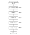
図4において、まず、CPU104は、受け付けた実行指示に含まれる第1の条件設定値を確認する(ステップS401)。次いで、CPU104は測定チャートを印刷するための印刷データを生成し、該印刷データに基づいて印刷を行う(ステップS402)。これにより、異なる色の複数のカラーパッチが用紙に印刷される。次いで、CPU104はセンサ114に測定指示を行う(ステップS403)。これにより、センサ114は用紙に印刷された各カラーパッチを測定し、各カラーパッチの測定結果をCPU104に送信する。CPU104はセンサ114から各カラーパッチの測定結果を取得し、各カラーパッチの測定結果及び第1の補正ターゲット情報に基づいて第1の補正LUTを生成する(ステップS404)。次いで、CPU104は第1の補正LUTに基づいてMFP101の画像形成関連値を補正し、第1の補正LUTをHDD107に格納し(ステップS405)、本処理を終了する。
In FIG. 4, first, the
図5は、図1の印刷システム100によって実行される第2のキャリブレーション実行処理の手順を示すフローチャートである。図5(a)は、図1の画像処理装置102によって実行される第2の補正LUT生成処理の手順を示し、図5(b)は、図1のMFP101によって実行される測定結果送信処理の手順を示す。
FIG. 5 is a flowchart showing a procedure of the second calibration execution process executed by the
図5(a)の処理は、画像処理装置102のCPU122がROM123やHDD125に格納されたプログラムを実行することによって行われ、画像処理装置102が第2の条件設定値を含むキャリブレーションの実行指示を受け付けた場合を前提とする。また、図5(b)の処理は、MFP101のCPU104がROM105やHDD107に格納されたプログラムを実行することによって行われる。
The process of FIG. 5A is performed by the
図5(a)において、まず、画像処理装置102のCPU122は、受け付けた実行指示に含まれる第2の条件設定値を確認し(ステップS501)、測定チャートを印刷するための印刷データを生成する(ステップS502)。次いで、CPU122は生成した印刷データをMFP101に送信する(ステップS503)。これにより、MFP101は、図5(b)を実行し、該印刷データに基づいて異なる色の複数のカラーパッチを用紙に印刷し、印刷した各カラーパッチを測定し、各カラーパッチの測定結果を画像処理装置102に送信する。次いで、CPU122は、画像処理装置102から各カラーパッチの測定結果を取得し(ステップS504)、取得した各カラーパッチの測定結果及び第2の補正ターゲット情報に基づいて第2の補正LUTを生成する(ステップS505)。次いで、CPU122は第2の補正LUTに基づいて画像パラメータを補正し、第2の補正LUTをHDD125に格納し(ステップS506)、本処理を終了する。
In FIG. 5A, first, the
図5(b)において、MFP101のCPU104は、画像処理装置102から印刷データを取得し(ステップS507)、取得した印刷データを解析し(ステップS508)、該印刷データの印刷を行う(ステップS509)。これにより、異なる色の複数のカラーパッチが用紙に印刷される。次いで、CPU104はセンサ114を制御して各カラーパッチを測定し(ステップS510)、各カラーパッチの測定結果を画像処理装置102に送信し(ステップS511)、本処理を終了する。
In FIG. 5B, the
次に、システムキャリブレーションの実行について説明する。 Next, the execution of system calibration will be described.
本実施の形態では、システムキャリブレーションの実行条件を示す第3の条件設定値が図6の第3の設定情報600に設定され、第3の設定情報600は画像処理装置102によって生成される。画像処理装置102はMFP101及び画像処理装置102が起動してMFP101及び画像処理装置102の間の通信が開始されたタイミングでMFP101から第1の設定情報301を取得する。画像処理装置102は第1の設定情報301及びHDD125に格納された第2の設定情報304に基づいて第3の設定情報600を生成する。生成された第3の設定情報600はHDD125に格納され、また、MFP101に送信される。画像処理装置102は第1のキャリブレーションが実行されたタイミング又は第2の設定情報304の各設定値が追加登録されたタイミングで第3の設定情報600を更新する。
In the present embodiment, a third condition setting value indicating an execution condition of the system calibration is set in the
第3の設定情報600は、設定名称601、設定602,603、及び最終実行時刻604を備える。設定名称601には第3の条件設定値を示す文字列が設定される。設定名称601には、第1の条件設定値及び第2の条件設定値のうち数の多い条件設定値、本実施の形態では、第2の条件設定値と同じ文字列が第3の条件設定値として設定される。すなわち、本実施の形態では、第2の条件設定値及び第3の条件設定値は実質的に同じである。設定602には第2の設定情報304の設定305に対応する文字列が設定される。設定603には第1の設定情報301の設定302に対応する文字列が設定される。設定603の各文字列は第1の条件設定値に対応し、各第1の条件設定値は同じ用紙の種別の第3の条件設定値に対応付けされている。例えば、「薄紙/普通紙/厚紙1−4」に対応する第1の条件設定値「キャリブレーション1」は、「普通紙」に対応する第3の条件設定値「普通紙」及び「厚紙2」に対応する第3の条件設定値「ユーザ用紙F」に対応付けされる。なお、本実施の形態では、第1の条件設定値の数は第3の条件設定値の数より少なく、各第1の条件設定値は少なくとも1つの第3の条件設定値に対応付けされる。最終実行時刻604には各第1の条件設定値の第1のキャリブレーションの最終実行時刻が設定される。
The
本実施の形態では、例えば、画像処理装置102の表示部132に表示される図7の設定画面700をユーザが操作することによってシステムキャリブレーションの実行指示が行われる。設定画面700は条件設定欄701及び実行ボタン702を備える。条件設定欄701には第3の設定情報600に含まれる複数の第3の条件設定値(第2の条件設定値)が表示され、実行ボタン702は条件設定欄701において選択された第3の条件設定値のシステムキャリブレーションの実行を指示する操作ボタンである。
In the present embodiment, for example, the user operates the
図8は、図1の画像処理装置102によって実行されるシステムキャリブレーション実行処理の手順を示すフローチャートである。
FIG. 8 is a flowchart showing a procedure of a system calibration execution process executed by the
図8の処理は、画像処理装置102のCPU122がROM123やHDD125に格納されたプログラムを実行することによって行われ、ユーザの設定画面700の操作によってシステムキャリブレーションの実行指示が行われた場合を前提とする。システムキャリブレーションの実行指示は第3の条件設定値(第2の条件設定値)を含む。
The process of FIG. 8 is performed by executing the program stored in the
図8において、まず、CPU122は、システムキャリブレーションの実行指示を受け付け(ステップS801)、該実行指示を解析する(ステップS802)。これにより、CPU122は、該実行指示に含まれる第3の条件設定値(第2の条件設定値)に基づいて第1の条件設定値及び第2の条件設定値を特定する。次いで、CPU122は特定された第1の条件設定値に基づいて第1のキャリブレーションの実行コマンドを生成する(ステップS803)。第1のキャリブレーションの実行コマンドはMFP101が第1のキャリブレーションを実行するためのコマンドファイルであり、第1の条件設定値を含む。次いで、CPU122はMFP101にキャリブレーションの実行指示として第1のキャリブレーションの実行コマンドを送信する(ステップS804)。これにより、MFP101は、後述する図9の結果コマンド送信処理を実行し、第1のキャリブレーション実行処理が正常に実行されたか否かを示す結果コマンドを画像処理装置102に送信する。次いで、CPU122は、MFP101から結果コマンドを受信し(ステップS805)、受信した結果コマンドに基づいて第1のキャリブレーション実行処理が正常に実行された否かを判別する(ステップS806)。
In FIG. 8, first, the
ステップS806の判別の結果、第1のキャリブレーション実行処理が正常に実行されないとき、CPU122は第1のキャリブレーションが失敗した旨を表示部132に表示し(ステップS807)、本処理を終了する。一方、ステップS806の判別の結果、第1のキャリブレーション実行処理が正常に実行されたとき、CPU122はシステムキャリブレーションの実行指示に基づいて図5(a)の第2の補正LUT生成処理を実行する(ステップS808)。次いで、CPU122は第2のキャリブレーション実行処理が正常に実行されたか否かを判別する(ステップS809)。
As a result of the determination in step S806, when the first calibration execution process is not normally executed, the
ステップS809の判別の結果、第2のキャリブレーション実行処理が正常に実行されたとき、CPU122はシステムキャリブレーションの実行が完了した旨を表示部132に表示し(ステップS810)、本処理を終了する。一方、ステップS809の判別の結果、第2のキャリブレーション実行処理が正常に実行されないとき、CPU122は第2のキャリブレーションが失敗した旨を表示部132に表示し(ステップS811)、本処理を終了する。
As a result of the determination in step S809, when the second calibration execution process is normally executed, the
図9は、図1のMFP101によって実行される結果コマンド送信処理の手順を示すフローチャートである。
FIG. 9 is a flowchart showing a procedure of result command transmission processing executed by the
図9の処理は、MFP101のCPU104がROM105やHDD107に格納されたプログラムを実行することによって行われる。
The process of FIG. 9 is performed by the
図9において、まず、CPU104は画像処理装置102から第1のキャリブレーションの実行コマンドを受信し(ステップS901)、図4の第1のキャリブレーション実行処理を実行する(ステップS902)。次いで、CPU104は、第1のキャリブレーション実行処理の実行を完了したか否かを判別する(ステップS903)。
In FIG. 9, first, the
ステップS903の判別の結果、第1のキャリブレーション実行処理の実行を完了したとき、CPU104は第1のキャリブレーション実行処理が正常に実行された旨を示す結果コマンドを生成する(ステップS904)。次いで、CPU104は生成した結果コマンドを画像処理装置102に送信し(ステップS905)、本処理を終了する。
As a result of the determination in step S903, when the execution of the first calibration execution process is completed, the
ステップS903の判別の結果、実行を開始してから所定の期間が経過しても第1のキャリブレーション実行処理の実行を完了しないとき、CPU104は第1のキャリブレーション実行処理の実行を失敗した旨を示す結果コマンドを生成する(ステップS906)。その後、CPU104はステップS905の処理を行う。
As a result of the determination in step S903, when the execution of the first calibration execution process is not completed even after a predetermined period has elapsed from the start of the execution, the
上述した本実施の形態によれば、システムキャリブレーションの実行指示に基づいて第1のキャリブレーションの実行コマンドが画像処理装置102からMFP101に送信され、MFP101から第1のキャリブレーション実行処理が正常に実行された旨を示す結果コマンドを受信した直後に(コマンドを受信したことに従い)画像処理装置102が第2のキャリブレーション実行処理の実行を開始する。これにより、第1のキャリブレーションを実行した後に第2のキャリブレーションを確実に実行することができ、もって、システムキャリブレーションを適切に行うことができる。
According to the above-described embodiment, the first calibration execution command is transmitted from the
また、上述した本実施の形態では、第1のキャリブレーションは、システムキャリブレーションの実行指示に含まれる第3の条件設定値、つまり、第2の条件設定値に対応付けされた実行条件に基づいて実行される。すなわち、システムキャリブレーションの実行指示には第1の条件設定値を設定する必要が無い。これにより、システムキャリブレーションの実行指示におけるユーザの設定の手間を軽減することができる。 Further, in the present embodiment described above, the first calibration is based on the third condition setting value included in the execution instruction of the system calibration, that is, the execution condition associated with the second condition setting value. Is executed. That is, it is not necessary to set the first condition setting value in the system calibration execution instruction. As a result, it is possible to reduce the trouble of setting the user in the execution instruction of the system calibration.
上述した本実施の形態では、設定画面700が表示部132に表示される場合について説明したが、設定画面700の表示先は表示部132に限られない。例えば、MFP101の表示部117やクライアントPC120等に表示されても良く、ユーザの設定画面700の操作によるシステムキャリブレーションの実行指示が画像処理装置102によって管理される構成であれば良い。
In the above-described embodiment, the case where the
また、上述した本実施の形態では、第3の設定情報600は、設定名称601の項目を含まなくても良く、設定画面700の条件設定欄701には複数の第2の条件設定値が表示されても良い。
Further, in the above-described embodiment, the
さらに、上述した本実施の形態では、第1のキャリブレーションの最終実行時刻に基づいて第1のキャリブレーションを実行するか否かを決定しても良い。 Further, in the present embodiment described above, it may be determined whether or not to execute the first calibration based on the final execution time of the first calibration.
ここで、第1の条件設定値の数は第3の条件設定値の数より少ない。そのため、第3の設定情報600において、異なる複数の第3の条件設定値に対し、同じ第1の条件設定値が対応付けされる場合がある。例えば、設定名称601における第3の条件設定値「普通紙」,「ユーザ用紙F」に対し、設定603では同じ第1の条件設定値「キャリブレーション1」が対応付けされる。「普通紙」及び「ユーザ用紙F」のシステムキャリブレーションの実行指示を連続して受け付けた場合、「キャリブレーション1」の第1のキャリブレーションを連続して実行することになる。つまり、本実施の形態では、第1のキャリブレーションにおいて、第2のキャリブレーションに比べ、同じ条件設定値の実行指示が行われる可能性が高い。通常、キャリブレーションはMFP101の周辺環境が変化した場合等に行われ、同じ条件設定値のキャリブレーションを短い間隔で実行する必要性は極めて低い。キャリブレーションの実行には、或る程度の時間を要するので、不要なキャリブレーションの実行は極力行わないことが好ましい。
Here, the number of the first condition setting values is smaller than the number of the third condition setting values. Therefore, in the
これに対して、本実施の形態では、第1のキャリブレーションの最終実行時刻に基づいて第1のキャリブレーションを実行するか否かを決定する。 On the other hand, in the present embodiment, it is determined whether or not to execute the first calibration based on the final execution time of the first calibration.
図10は、図8のシステムキャリブレーション実行処理の変形例の手順を示すフローチャートである。 FIG. 10 is a flowchart showing a procedure of a modification of the system calibration execution process of FIG.
図10の処理は、画像処理装置102のCPU122がROM123やHDD125に格納されたプログラムを実行することによって行われ、ユーザの設定画面700の操作によってシステムキャリブレーションの実行指示が行われた場合を前提とする。
The process of FIG. 10 is performed by executing the program stored in the
図10において、まず、CPU122はステップS801、S802の処理を行う。次いで、CPU122は第3の設定情報600に基づいて上記実行指示に対応する第1のキャリブレーションの最終実行時刻を確認する(ステップS1001)。次いで、CPU122は、第1のキャリブレーションの実行を完了してから、予め設定された所定の期間が経過したか否かを判別する(ステップS1002)。
In FIG. 10, first, the
ステップS1002の判別の結果、第1のキャリブレーションの実行を完了してから所定の期間が経過しないとき、CPU122は、第1のキャリブレーション実行処理を行わず、ステップS808以降の処理を行う。一方、ステップS1002の判別の結果、第1のキャリブレーションの実行を完了してから所定の期間が経過したとき、CPU122はステップS803以降の処理を行う。
As a result of the determination in step S1002, when a predetermined period has not elapsed since the execution of the first calibration was completed, the
上述した本実施の形態では、第1のキャリブレーションの最終実行時刻に基づいて第1のキャリブレーションを実行するか否かが決定される。これにより、同じ設定値の第1のキャリブレーションが短い間隔で実行されるのを防止することができる。 In the present embodiment described above, it is determined whether or not to execute the first calibration based on the final execution time of the first calibration. This makes it possible to prevent the first calibration of the same set value from being performed at short intervals.
また、上述した本実施の形態では、設定画面700に、第1のキャリブレーションを実行するか否かを選択させる図11のチェックボックス1101を備えても良い。画像処理装置102は、条件設定欄701において第3の条件設定値を設定し且つ実行ボタン702を選択した際にチェックボックス1101が選択されている場合、システムキャリブレーションにおいて第1のキャリブレーションを実行しないと判別する。一方、条件設定欄701において第3の条件設定値を設定し且つ実行ボタン702を選択した際にチェックボックス1101が選択されていない場合、システムキャリブレーションにおいて第1のキャリブレーションを実行すると判別する。
Further, in the above-described embodiment, the
これにより、システムキャリブレーションにおける第1のキャリブレーションの実行の決定において、ユーザの意図を反映させることができ、もって、システムキャリブレーションを柔軟に処理することができる。 As a result, the intention of the user can be reflected in the decision to execute the first calibration in the system calibration, and the system calibration can be processed flexibly.
さらに、上述した本実施の形態では、第1のキャリブレーションを実行してから予め設定された所定の期間が経過した場合、設定画面700にチェックボックス1101を表示しても良い。これにより、同じ設定値の第1のキャリブレーションが短い間隔で実行されるのを防止することと、システムキャリブレーションを柔軟に処理することとを両立することができる。
Further, in the above-described embodiment, the
次に、本発明の第2の実施の形態について説明する。 Next, a second embodiment of the present invention will be described.
本発明の第2の実施の形態は、その構成、作用が上述した第1の実施の形態と基本的に同じである。しかし、MFP101がセンサ制御モジュールを備える点で本発明の第1の実施の形態と異なるため、以下、重複した構成、作用については説明を省略し、異なる構成、作用についての説明を行う。
The second embodiment of the present invention is basically the same as the first embodiment described above in its configuration and operation. However, since the
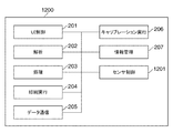
図12は、第2の実施の形態におけるMFP101のソフトウェアモジュール1200の構成を説明するための図である。
FIG. 12 is a diagram for explaining the configuration of the
図12において、ソフトウェアモジュール1200は、ソフトウェアモジュール200の各構成要素の他に、センサ制御モジュール1201を備える。ソフトウェアモジュール1200の各処理は、MFP101のCPU104がROM105やHDD107に格納されたプログラムを実行することによって行われる。
In FIG. 12, the
センサ制御モジュール1201はセンサ114の測定に関する各処理の実行を制御する。例えば、センサ制御モジュール1201は、測定前に行われるセンサ114の準備動作の実行を制御する。準備動作は、例えば、センサ114及びセンサI/F110の接続確認動作、センサ114の図示しない照明光源の自己昇温が安定するまで該照明光源を強制的に発光させる暖気動作、該照明光源の光量を調整する光量調整動作、及びセンサ114の読み取り異常検知動作である。センサ114の読み取り異常検知動作では、センサ114による読み取りの異常を検出するために、センサ114が該センサ114の近傍に配置された図示しない白色基準板を測定し、測定値が一定の基準範囲内に収まるか否かを確認する。
The
図13は、図4の第1のキャリブレーション実行処理の変形例の手順を示すフローチャートである。 FIG. 13 is a flowchart showing a procedure of a modification of the first calibration execution process of FIG.
図13の処理は、MFP101のCPU104がROM105やHDD107に格納されたプログラムを実行することによって行われ、MFP101が第1の条件設定値を含むキャリブレーションの実行指示を受け付けた場合を前提とする。
The process of FIG. 13 is performed by executing the program stored in the
ここで、印刷システム100では、第1のキャリブレーション及び第2のキャリブレーションの実行時にカラーパッチを測定する事前準備としてセンサ114の準備動作が行われる。センサ114は準備動作を完了すると、測定可能状態(検知可能状態)に移行し、カラーパッチの測定が可能になる。準備動作の実行には数十秒程度の時間を要する。印刷システム100は、キャリブレーションの実行指示が行われてから極力短い期間で該キャリブレーションの実行を完了することが好ましく、このため、準備動作の実行回数を必要最小限にする必要がある。また、準備動作の実行回数が増える毎にセンサ114の機械寿命が短くなるので、センサ114の機械寿命の低下を抑制する観点からも準備動作の実行回数を必要最小限にする必要がある。
Here, in the
これに対応して、本実施の形態では、センサ114では、システムキャリブレーションの実行指示に基づいて第1のキャリブレーションを実行した際に測定可能状態に移行すると、システムキャリブレーションの実行指示に対応する全てのキャリブレーションの実行が完了するまで測定可能状態が維持される。 Corresponding to this, in the present embodiment, when the sensor 114 shifts to the measurable state when the first calibration is executed based on the system calibration execution instruction, the sensor 114 corresponds to the system calibration execution instruction. The measurable state is maintained until all the calibrations to be performed are completed.
図13において、まず、CPU104はステップS401の処理を実行する。次いで、CPU104はセンサ114の準備動作を開始し(ステップS1301)、センサ114を測定可能状態に移行させる(ステップS1302)。これにより、センサ114はカラーパッチの測定が可能になり、MFP101ではセンサ114を停止させない限り該センサ114の準備動作が不要となる。次いで、CPU104はステップS402〜S405の処理を実行する。次いで、CPU104は第1のキャリブレーションの実行がシステムキャリブレーションの実行指示によるものであるか否かを判別する(ステップS1303)。
In FIG. 13, first, the
ステップS1303の判別の結果、第1のキャリブレーションの実行がシステムキャリブレーションの実行指示によるものであるとき、CPU104はセンサ114を測定可能状態に維持したまま、本処理を終了する。一方、第1のキャリブレーションの実行がシステムキャリブレーションの実行指示によるものでないとき、CPU104はセンサ114を停止させ(ステップS1304)、本処理を終了する。
As a result of the determination in step S1303, when the execution of the first calibration is based on the execution instruction of the system calibration, the
図14は、図5(b)の測定結果送信処理の変形例の手順を示すフローチャートである。 FIG. 14 is a flowchart showing a procedure of a modification of the measurement result transmission process of FIG. 5 (b).
図14の処理は、MFP101のCPU104がROM105やHDD107に格納されたプログラムを実行することによって行われる。図14の処理は、画像処理装置102が第2の条件設定値を含むキャリブレーションの実行指示を受け付けた場合を前提とする。
The process of FIG. 14 is performed by the
図14において、まず、CPU104はステップS507、S508の処理を行う。次いで、CPU104はセンサ114が測定可能状態であるか否かを判別する(ステップS1401)。
In FIG. 14, first, the
ステップS1401の判別の結果、センサ114が測定可能状態であるとき、CPU104は、センサ114の準備動作を行う必要がないので、センサ114の準備動作を行わず、ステップS509〜S511の処理を行う。一方、ステップS1401の判別の結果、センサ114が測定可能状態でないとき、CPU104はセンサ114の準備動作を開始し(ステップS1402)、センサ114を測定可能状態に移行させる(ステップS1403)。次いで、CPU104はステップS509〜S511の処理を行う。次いで、CPU104はセンサ114を停止し(ステップS1404)、本処理を終了する。
As a result of the determination in step S1401, when the sensor 114 is in the measurable state, the
上述した本実施の形態では、センサ114では、システムキャリブレーションの実行指示に基づいて第1のキャリブレーションを実行した際に測定可能状態に移行すると、システムキャリブレーションの実行指示に対応する全てのキャリブレーションの実行が完了するまで測定可能状態が維持される。これにより、不要な準備動作の実行に起因するキャリブレーション実行の遅滞及びセンサ114の機械寿命の低下を抑制することができる。 In the above-described embodiment, when the sensor 114 shifts to the measurable state when the first calibration is executed based on the system calibration execution instruction, all the calibrations corresponding to the system calibration execution instruction are performed. The measurable state is maintained until the execution of the test is completed. As a result, it is possible to suppress the delay in calibration execution and the reduction in the mechanical life of the sensor 114 due to the execution of unnecessary preparatory operations.
上述した本実施の形態では、第1のキャリブレーションが実行されてから予め設定された状態維持期間が経過した場合、センサ114を停止させても良い。これにより、準備動作の実行を抑制するためにセンサ114が必要以上に動作し続けることを防止することができ、もって、センサ114の消費電力の増加を抑制することができる。 In the present embodiment described above, the sensor 114 may be stopped when a preset state maintenance period has elapsed since the first calibration was executed. As a result, it is possible to prevent the sensor 114 from continuing to operate more than necessary in order to suppress the execution of the preparatory operation, and thus it is possible to suppress an increase in the power consumption of the sensor 114.
また、上述した本実施の形態では、準備動作は、センサ114の接続確認動作、センサ114の光源の暖気動作、該光源の光量を調整する光量調整動作、及びセンサ114の読み取り異常検知動作のうち少なくとも1つである。これにより、センサ114の接続確認動作、センサ114の光源の暖気動作、該光源の光量を調整する光量調整動作、及びセンサ114の読み取り異常検知動作に起因するキャリブレーションの実行の遅滞及びセンサ114の機械寿命の低下を確実に抑制することができる。 Further, in the above-described embodiment, the preparatory operation includes the connection confirmation operation of the sensor 114, the warm-up operation of the light source of the sensor 114, the light amount adjustment operation of adjusting the light amount of the light source, and the reading abnormality detection operation of the sensor 114. At least one. As a result, the connection confirmation operation of the sensor 114, the warm-up operation of the light source of the sensor 114, the light amount adjustment operation of adjusting the light amount of the light source, the delay of calibration execution due to the reading abnormality detection operation of the sensor 114, and the delay of the execution of the calibration of the sensor 114. The decrease in machine life can be reliably suppressed.
本発明は、上述の実施の形態の1以上の機能を実現するプログラムをネットワーク又は記憶媒体を介してシステム又は装置に供給し、該システム又は装置のコンピュータにおける1つ以上のプロセッサがプログラムを読み出して実行する処理でも実現可能である。また、本発明は、1以上の機能を実現する回路(例えば、ASIC)によっても実現可能である。 The present invention supplies a program that realizes one or more functions of the above-described embodiment to a system or device via a network or storage medium, and one or more processors in the computer of the system or device read the program. It can also be realized by the processing to be executed. The present invention can also be realized by a circuit (for example, ASIC) that realizes one or more functions.
100 印刷システム
101 MFP
102 画像処理装置
104,122 CPU
114 センサ
205,212 データ通信モジュール
206,213 キャリブレーション実行モジュール
215 システムキャリブレーション実行モジュール
600 第3の設定情報
700 設定画面
1101 チェックボックス
100
102
114
Claims (14)
前記第1のキャリブレーション及び前記第2のキャリブレーションの実行に用いる検知部と、
前記第1のキャリブレーション及び前記第2のキャリブレーションを実行する指示を前記画像処理装置によって受け付ける受付手段と、
前記受付手段によって受け付けた前記指示に基づいて、前記第1のキャリブレーションを実行するための実行コマンドを前記画像処理装置から前記印刷装置に送信する第1の送信手段と、
前記実行コマンドに対応する前記第1のキャリブレーションの実行が完了した旨を示す通知を、前記印刷装置から前記画像処理装置に送信する第2の送信手段と、
前記画像処理装置が前記通知を受信したことに従って、前記第2のキャリブレーションの実行を開始させる制御手段とを備え、
前記指示に基づいて、所定の動作を行って前記検知部を検知可能状態に移行させ、前記第1のキャリブレーションと前記第2のキャリブレーションの実行が完了するまで前記検知可能状態が維持されることを特徴とする印刷システム。 A printing system including a printing device that controls the execution of the first calibration and an image processing device that controls the execution of the second calibration.
The detector used to execute the first calibration and the second calibration, and
A receiving means for receiving an instruction to execute the first calibration and the second calibration by the image processing device, and
A first transmitting means for transmitting an execution command for executing the first calibration from the image processing device to the printing device based on the instruction received by the receiving means.
A second transmission means for transmitting a notification indicating that the execution of the first calibration corresponding to the execution command is completed from the printing device to the image processing device, and
The image processing apparatus includes a control means for initiating the execution of the second calibration upon receiving the notification .
Based on the instruction, performs a predetermined operation to shift the detection unit to the detection state, the detection state is Ru is maintained until the execution of the first calibration and the second calibration is completed A printing system characterized by that.
前記第2のキャリブレーションは、前記第2のキャリブレーションの実行条件に基づいて実行され、
前記第1のキャリブレーションは、前記第2のキャリブレーションの実行条件に対応付けられた実行条件に基づいて実行されることを特徴とする請求項1記載の印刷システム。 The instruction includes the execution condition of the second calibration.
The second calibration is executed based on the execution conditions of the second calibration.
The printing system according to claim 1, wherein the first calibration is executed based on an execution condition associated with the execution condition of the second calibration.
前記第1のキャリブレーションの実行時刻に基づいて該第1のキャリブレーションを実行するか否かを判別することを特徴とする請求項1又は2記載の印刷システム。 The execution time of the first calibration is managed,
The printing system according to claim 1 or 2, wherein it is determined whether or not to execute the first calibration based on the execution time of the first calibration.
前記設定画面には、前記第1のキャリブレーションを実行してから予め設定された所定の期間が経過した場合、前記第1のキャリブレーションを実行するか否かを選択させる選択手段が表示されることを特徴とする請求項1乃至3のいずれか1項に記載の印刷システム。 Display the setting screen that accepts the above instructions,
On the setting screen, a selection means for selecting whether or not to execute the first calibration is displayed when a predetermined predetermined period has elapsed since the first calibration was executed. The printing system according to any one of claims 1 to 3, wherein the printing system is characterized in that.
前記所定の動作は、前記センサの接続確認動作、前記センサの光源の暖気動作、前記光源の光量を調整する光量調整動作、及び前記センサの読み取り異常検知動作のうち少なくとも1つであることを特徴とする請求項1乃至5のいずれか1項に記載の印刷システム。 The detection unit is a sensor including a light source.
The predetermined operation is characterized in that it is at least one of a connection confirmation operation of the sensor, a warm-up operation of the light source of the sensor, a light amount adjustment operation of adjusting the light amount of the light source, and a reading abnormality detection operation of the sensor. The printing system according to any one of claims 1 to 5 .
前記第2のキャリブレーションの実行を制御するキャリブレーション実行手段と、
前記第1のキャリブレーション及び前記第2のキャリブレーションを実行する指示を受け付ける受付手段と、
前記受付手段によって受け付けた前記指示に基づいて、前記第1のキャリブレーションを実行するための実行コマンドを前記印刷装置に送信する送信手段と、
前記実行コマンドに対応する前記第1のキャリブレーションの実行が完了した旨を示す通知を、前記印刷装置から受信する受信手段と、
前記通知を受信したことに従って、前記第2のキャリブレーションの実行を開始させる制御手段とを備え、
前記指示に基づいて、前記検知部に所定の動作を行わせて前記検知部を検知可能状態に移行させ、前記第1のキャリブレーションと前記第2のキャリブレーションの実行が完了するまで前記検知可能状態が維持されることを特徴とする画像処理装置。 Image processing that communicates with a printing device that controls the execution of the first calibration and includes a detection unit used to execute the first calibration and the second calibration different from the first calibration. It ’s a device,
And calibration execution means for controlling the execution of the previous SL second calibration,
A receiving means for receiving an instruction to execute the first calibration and the second calibration, and
A transmission means for transmitting an execution command for executing the first calibration to the printing device based on the instruction received by the reception means, and
A receiving means for receiving a notification from the printing apparatus indicating that the execution of the first calibration corresponding to the execution command is completed, and
A control means for initiating the execution of the second calibration according to the receipt of the notification is provided .
Based on the instruction, the detection unit is made to perform a predetermined operation to shift the detection unit to a detectable state, and the detection is possible until the execution of the first calibration and the second calibration is completed. the image processing apparatus according to claim Rukoto state is maintained.
前記第2のキャリブレーションは、前記第2のキャリブレーションの実行条件に基づいて実行され、
前記第1のキャリブレーションは、前記第2のキャリブレーションの実行条件に対応付けられた実行条件に基づいて実行されることを特徴とする請求項8記載の画像処理装置。 The instruction includes the execution condition of the second calibration.
The second calibration is executed based on the execution conditions of the second calibration.
The image processing apparatus according to claim 8, wherein the first calibration is executed based on an execution condition associated with the execution condition of the second calibration.
前記第1のキャリブレーションの実行時刻に基づいて該第1のキャリブレーションを実行するか否かを判別することを特徴とする請求項8又は9記載の画像処理装置。 The execution time of the first calibration is managed,
The image processing apparatus according to claim 8 or 9, wherein it is determined whether or not to execute the first calibration based on the execution time of the first calibration.
前記設定画面には、前記第1のキャリブレーションを実行してから予め設定された所定の期間が経過した場合、前記第1のキャリブレーションを実行するか否かを選択させる選択手段が表示されることを特徴とする請求項8乃至10のいずれか1項に記載の画像処理装置。 Display the setting screen that accepts the above instructions,
On the setting screen, a selection means for selecting whether or not to execute the first calibration is displayed when a predetermined predetermined period set in advance has elapsed since the first calibration was executed. The image processing apparatus according to any one of claims 8 to 10.
前記第1のキャリブレーション及び前記第2のキャリブレーションを実行する指示を前記画像処理装置によって受け付ける受付ステップと、
前記受付ステップで受け付けた前記指示に基づいて、前記第1のキャリブレーションを実行するための実行コマンドを前記画像処理装置から前記印刷装置に送信する第1の送信ステップと、
前記実行コマンドに対応する前記第1のキャリブレーションの実行が完了した旨を示す通知を、前記印刷装置から前記画像処理装置に送信する第2の送信ステップと、
前記画像処理装置が前記通知を受信したことに従って、前記第2のキャリブレーションの実行を開始させる制御ステップとを有し、
前記指示に基づいて、前記検知部に所定の動作を行わせて前記検知部を検知可能状態に移行させ、前記第1のキャリブレーションと前記第2のキャリブレーションの実行が完了するまで前記検知可能状態が維持されることを特徴とするキャリブレーション制御方法。 Printing apparatus for controlling the execution of the first calibration, the image processing apparatus for controlling execution of the second calibration and printing comprising a detection unit used in the execution of the first calibration and the second calibration A calibration control method performed in the system
A reception step for receiving an instruction to execute the first calibration and the second calibration by the image processing device, and
A first transmission step of transmitting an execution command for executing the first calibration from the image processing device to the printing device based on the instruction received in the reception step.
A second transmission step of transmitting a notification indicating that the execution of the first calibration corresponding to the execution command is completed from the printing device to the image processing device, and
According to the image processing apparatus receives the notification, have a control step of starting the execution of the second calibration,
Based on the instruction, the detection unit is made to perform a predetermined operation to shift the detection unit to a detectable state, and the detection is possible until the execution of the first calibration and the second calibration is completed. calibration control method comprising Rukoto state is maintained.
前記キャリブレーション制御方法は、
前記第1のキャリブレーション及び前記第2のキャリブレーションを実行する指示を前記画像処理装置によって受け付ける受付ステップと、
前記受付ステップで受け付けた前記指示に基づいて、前記第1のキャリブレーションを実行するための実行コマンドを前記画像処理装置から前記印刷装置に送信する第1の送信ステップと、
前記実行コマンドに対応する前記第1のキャリブレーションの実行が完了した旨を示す通知を、前記印刷装置から前記画像処理装置に送信する第2の送信ステップと、
前記画像処理装置が前記通知を受信したことに従って、前記第2のキャリブレーションの実行を開始させる制御ステップとを有し、
前記指示に基づいて、前記検知部に所定の動作を行わせて前記検知部を検知可能状態に移行させ、前記第1のキャリブレーションと前記第2のキャリブレーションの実行が完了するまで前記検知可能状態が維持されることを特徴とするプログラム。 Printing apparatus for controlling the execution of the first calibration, the image processing apparatus for controlling execution of the second calibration and printing comprising a detection unit used in the execution of the first calibration and the second calibration A program that causes a computer to execute the calibration control method executed in the system.
The calibration control method is
A reception step for receiving an instruction to execute the first calibration and the second calibration by the image processing device, and
A first transmission step of transmitting an execution command for executing the first calibration from the image processing device to the printing device based on the instruction received in the reception step.
A second transmission step of transmitting a notification indicating that the execution of the first calibration corresponding to the execution command is completed from the printing device to the image processing device, and
According to the image processing apparatus receives the notification, have a control step of starting the execution of the second calibration,
Based on the instruction, the detection unit is made to perform a predetermined operation to shift the detection unit to a detectable state, and the detection is possible until the execution of the first calibration and the second calibration is completed. program characterized Rukoto state is maintained.
Priority Applications (2)
| Application Number | Priority Date | Filing Date | Title |
|---|---|---|---|
| JP2016218972A JP6815837B2 (en) | 2016-11-09 | 2016-11-09 | Printing system, image processing equipment, calibration control method, and program |
| US15/788,019 US10506108B2 (en) | 2016-11-09 | 2017-10-19 | Image processing apparatus generating print data, print system including image processing apparatus and printing apparatus printing based on print data, calibration control method in print system, and storage medium storing calibration control program |
Applications Claiming Priority (1)
| Application Number | Priority Date | Filing Date | Title |
|---|---|---|---|
| JP2016218972A JP6815837B2 (en) | 2016-11-09 | 2016-11-09 | Printing system, image processing equipment, calibration control method, and program |
Publications (3)
| Publication Number | Publication Date |
|---|---|
| JP2018075766A JP2018075766A (en) | 2018-05-17 |
| JP2018075766A5 JP2018075766A5 (en) | 2019-12-19 |
| JP6815837B2 true JP6815837B2 (en) | 2021-01-20 |
Family
ID=62064190
Family Applications (1)
| Application Number | Title | Priority Date | Filing Date |
|---|---|---|---|
| JP2016218972A Active JP6815837B2 (en) | 2016-11-09 | 2016-11-09 | Printing system, image processing equipment, calibration control method, and program |
Country Status (2)
| Country | Link |
|---|---|
| US (1) | US10506108B2 (en) |
| JP (1) | JP6815837B2 (en) |
Families Citing this family (5)
| Publication number | Priority date | Publication date | Assignee | Title |
|---|---|---|---|---|
| JP7159725B2 (en) * | 2018-09-13 | 2022-10-25 | 富士フイルムビジネスイノベーション株式会社 | Image forming device and program |
| JP7187334B2 (en) * | 2019-01-18 | 2022-12-12 | キヤノン株式会社 | PRINTING APPARATUS, PRINTING APPARATUS CONTROL METHOD, CONTROL SYSTEM, AND PROGRAM |
| JP7383431B2 (en) * | 2019-09-11 | 2023-11-20 | キヤノン株式会社 | Image forming device |
| JP2021107127A (en) * | 2019-12-27 | 2021-07-29 | キヤノン株式会社 | Control apparatus, control method, and program |
| JP2024014529A (en) * | 2022-07-22 | 2024-02-01 | キヤノン株式会社 | Information processing device, method and program |
Family Cites Families (8)
| Publication number | Priority date | Publication date | Assignee | Title |
|---|---|---|---|---|
| JP2000318266A (en) * | 1999-05-12 | 2000-11-21 | Canon Inc | Calibration method, information processor and information processing system |
| JP4350543B2 (en) * | 2004-02-05 | 2009-10-21 | キヤノン株式会社 | Image processing apparatus, processing method in image processing apparatus, and program |
| JP2005236772A (en) * | 2004-02-20 | 2005-09-02 | Canon Inc | Processing method in image processing unit, image processing unit, and program |
| US20070177232A1 (en) * | 2006-02-02 | 2007-08-02 | Naoki Takeuchi | Image forming apparatus, calibration control method, and storage medium |
| JP2009289009A (en) * | 2008-05-29 | 2009-12-10 | Brother Ind Ltd | Print system, program, and printer |
| JP5990093B2 (en) * | 2012-11-29 | 2016-09-07 | キヤノン株式会社 | Image processing apparatus, image processing method, and program |
| JP6071513B2 (en) * | 2012-12-12 | 2017-02-01 | キヤノン株式会社 | Image processing apparatus, image forming apparatus, method and program thereof |
| JP2016102973A (en) * | 2014-11-28 | 2016-06-02 | キヤノン株式会社 | Image forming apparatus |
-
2016
- 2016-11-09 JP JP2016218972A patent/JP6815837B2/en active Active
-
2017
- 2017-10-19 US US15/788,019 patent/US10506108B2/en active Active
Also Published As
| Publication number | Publication date |
|---|---|
| US20180131818A1 (en) | 2018-05-10 |
| US10506108B2 (en) | 2019-12-10 |
| JP2018075766A (en) | 2018-05-17 |
Similar Documents
| Publication | Publication Date | Title |
|---|---|---|
| JP6815837B2 (en) | Printing system, image processing equipment, calibration control method, and program | |
| US11831847B2 (en) | Image processing apparatus, image processing method, and program for forming correcting color image data for each paper type | |
| JP6071513B2 (en) | Image processing apparatus, image forming apparatus, method and program thereof | |
| JP5751283B2 (en) | Color adjustment system, color adjustment method, and color adjustment program | |
| US8958128B2 (en) | Color image processing apparatus and method for processing color image | |
| US9239976B2 (en) | Image processing apparatus, image processing method, and program | |
| US9571701B2 (en) | Information processing apparatus, control method for information processing apparatus, and image forming system | |
| JP6381227B2 (en) | Calibration apparatus and calibration method | |
| US20200183627A1 (en) | Management system, information processing apparatus, control method therefor, and storage medium | |
| JP2018156375A (en) | Image forming device and control method therefor, and program | |
| JP2000318266A (en) | Calibration method, information processor and information processing system | |
| JP2016102973A (en) | Image forming apparatus | |
| US10354174B2 (en) | Image processing apparatus, image forming apparatus, method of controlling image processing apparatus, and method of controlling image forming apparatus | |
| US20180012113A1 (en) | Print system, print apparatus, method of controlling the same and storage medium | |
| US8786921B2 (en) | Image forming apparatus and system configured to perform color correction based on medium type | |
| JP2015103206A (en) | Image forming system, image processor, image forming apparatus, control method thereof, and program | |
| JP2010105311A (en) | Printer, control method and program | |
| US11323593B1 (en) | Methods and system for managing icc profiles within a color printing system | |
| JP2006209407A (en) | Remote calibration method | |
| US10620886B2 (en) | Image forming apparatus, image forming method, and recording medium | |
| US8842323B2 (en) | Print engine for printing a print job using appropriate calibration data | |
| JP2010109810A (en) | Information processing apparatus, information processing method, and program | |
| US11954542B2 (en) | Information processing apparatus, method, and storage medium for storing program | |
| JP2014229064A (en) | Information processor, information processing method, information processing program, and recording medium | |
| US11789394B2 (en) | Print system, printing apparatus, information processing apparatus, method of controlling the same, and storage medium |
Legal Events
| Date | Code | Title | Description |
|---|---|---|---|
| A521 | Written amendment |
Free format text: JAPANESE INTERMEDIATE CODE: A523 Effective date: 20191107 |
|
| A621 | Written request for application examination |
Free format text: JAPANESE INTERMEDIATE CODE: A621 Effective date: 20191107 |
|
| A977 | Report on retrieval |
Free format text: JAPANESE INTERMEDIATE CODE: A971007 Effective date: 20200910 |
|
| A131 | Notification of reasons for refusal |
Free format text: JAPANESE INTERMEDIATE CODE: A131 Effective date: 20200915 |
|
| A521 | Written amendment |
Free format text: JAPANESE INTERMEDIATE CODE: A523 Effective date: 20201116 |
|
| TRDD | Decision of grant or rejection written | ||
| A01 | Written decision to grant a patent or to grant a registration (utility model) |
Free format text: JAPANESE INTERMEDIATE CODE: A01 Effective date: 20201124 |
|
| A61 | First payment of annual fees (during grant procedure) |
Free format text: JAPANESE INTERMEDIATE CODE: A61 Effective date: 20201223 |
|
| R151 | Written notification of patent or utility model registration |
Ref document number: 6815837 Country of ref document: JP Free format text: JAPANESE INTERMEDIATE CODE: R151 |