JP6257219B2 - Image reading device - Google Patents
Image reading device Download PDFInfo
- Publication number
- JP6257219B2 JP6257219B2 JP2013173385A JP2013173385A JP6257219B2 JP 6257219 B2 JP6257219 B2 JP 6257219B2 JP 2013173385 A JP2013173385 A JP 2013173385A JP 2013173385 A JP2013173385 A JP 2013173385A JP 6257219 B2 JP6257219 B2 JP 6257219B2
- Authority
- JP
- Japan
- Prior art keywords
- reading
- unit
- adf
- transmission member
- calibration
- Prior art date
- Legal status (The legal status is an assumption and is not a legal conclusion. Google has not performed a legal analysis and makes no representation as to the accuracy of the status listed.)
- Expired - Fee Related
Links
Images


Classifications
-
- H—ELECTRICITY
- H04—ELECTRIC COMMUNICATION TECHNIQUE
- H04N—PICTORIAL COMMUNICATION, e.g. TELEVISION
- H04N1/00—Scanning, transmission or reproduction of documents or the like, e.g. facsimile transmission; Details thereof
- H04N1/00795—Reading arrangements
- H04N1/00798—Circuits or arrangements for the control thereof, e.g. using a programmed control device or according to a measured quantity
- H04N1/00819—Self-calibrating reading means
-
- H—ELECTRICITY
- H04—ELECTRIC COMMUNICATION TECHNIQUE
- H04N—PICTORIAL COMMUNICATION, e.g. TELEVISION
- H04N1/00—Scanning, transmission or reproduction of documents or the like, e.g. facsimile transmission; Details thereof
- H04N1/00002—Diagnosis, testing or measuring; Detecting, analysing or monitoring not otherwise provided for
- H04N1/00007—Diagnosis, testing or measuring; Detecting, analysing or monitoring not otherwise provided for relating to particular apparatus or devices
- H04N1/00013—Reading apparatus
-
- H—ELECTRICITY
- H04—ELECTRIC COMMUNICATION TECHNIQUE
- H04N—PICTORIAL COMMUNICATION, e.g. TELEVISION
- H04N1/00—Scanning, transmission or reproduction of documents or the like, e.g. facsimile transmission; Details thereof
- H04N1/00002—Diagnosis, testing or measuring; Detecting, analysing or monitoring not otherwise provided for
- H04N1/00026—Methods therefor
- H04N1/00042—Monitoring, i.e. observation
-
- H—ELECTRICITY
- H04—ELECTRIC COMMUNICATION TECHNIQUE
- H04N—PICTORIAL COMMUNICATION, e.g. TELEVISION
- H04N1/00—Scanning, transmission or reproduction of documents or the like, e.g. facsimile transmission; Details thereof
- H04N1/00002—Diagnosis, testing or measuring; Detecting, analysing or monitoring not otherwise provided for
- H04N1/00026—Methods therefor
- H04N1/00045—Methods therefor using a reference pattern designed for the purpose, e.g. a test chart
-
- H—ELECTRICITY
- H04—ELECTRIC COMMUNICATION TECHNIQUE
- H04N—PICTORIAL COMMUNICATION, e.g. TELEVISION
- H04N1/00—Scanning, transmission or reproduction of documents or the like, e.g. facsimile transmission; Details thereof
- H04N1/00002—Diagnosis, testing or measuring; Detecting, analysing or monitoring not otherwise provided for
- H04N1/00026—Methods therefor
- H04N1/0005—Methods therefor in service, i.e. during normal operation
-
- H—ELECTRICITY
- H04—ELECTRIC COMMUNICATION TECHNIQUE
- H04N—PICTORIAL COMMUNICATION, e.g. TELEVISION
- H04N1/00—Scanning, transmission or reproduction of documents or the like, e.g. facsimile transmission; Details thereof
- H04N1/00002—Diagnosis, testing or measuring; Detecting, analysing or monitoring not otherwise provided for
- H04N1/00026—Methods therefor
- H04N1/00063—Methods therefor using at least a part of the apparatus itself, e.g. self-testing
-
- H—ELECTRICITY
- H04—ELECTRIC COMMUNICATION TECHNIQUE
- H04N—PICTORIAL COMMUNICATION, e.g. TELEVISION
- H04N1/00—Scanning, transmission or reproduction of documents or the like, e.g. facsimile transmission; Details thereof
- H04N1/00002—Diagnosis, testing or measuring; Detecting, analysing or monitoring not otherwise provided for
- H04N1/00071—Diagnosis, testing or measuring; Detecting, analysing or monitoring not otherwise provided for characterised by the action taken
- H04N1/00082—Adjusting or controlling
- H04N1/00087—Setting or calibrating
-
- H—ELECTRICITY
- H04—ELECTRIC COMMUNICATION TECHNIQUE
- H04N—PICTORIAL COMMUNICATION, e.g. TELEVISION
- H04N1/00—Scanning, transmission or reproduction of documents or the like, e.g. facsimile transmission; Details thereof
- H04N1/40—Picture signal circuits
- H04N1/407—Control or modification of tonal gradation or of extreme levels, e.g. background level
- H04N1/4076—Control or modification of tonal gradation or of extreme levels, e.g. background level dependent on references outside the picture
-
- H—ELECTRICITY
- H04—ELECTRIC COMMUNICATION TECHNIQUE
- H04N—PICTORIAL COMMUNICATION, e.g. TELEVISION
- H04N1/00—Scanning, transmission or reproduction of documents or the like, e.g. facsimile transmission; Details thereof
- H04N1/04—Scanning arrangements, i.e. arrangements for the displacement of active reading or reproducing elements relative to the original or reproducing medium, or vice versa
- H04N1/10—Scanning arrangements, i.e. arrangements for the displacement of active reading or reproducing elements relative to the original or reproducing medium, or vice versa using flat picture-bearing surfaces
- H04N1/1013—Scanning arrangements, i.e. arrangements for the displacement of active reading or reproducing elements relative to the original or reproducing medium, or vice versa using flat picture-bearing surfaces with sub-scanning by translatory movement of at least a part of the main-scanning components
Landscapes
- Engineering & Computer Science (AREA)
- Multimedia (AREA)
- Signal Processing (AREA)
- Health & Medical Sciences (AREA)
- Biomedical Technology (AREA)
- General Health & Medical Sciences (AREA)
- Facsimile Scanning Arrangements (AREA)
- Image Input (AREA)
Description
本発明は、フラットベッド透過部材上の原稿の読み取りと自動原稿搬送装置から搬送されてきた原稿の読み取りを切り替えて行うことができる画像読取装置および画像読取方法に関するものである。 The present invention relates to an image reading apparatus and an image reading method capable of switching between reading of an original on a flat bed transmitting member and reading of an original conveyed from an automatic original conveying apparatus.
フラットベッド(FB)型画像読取装置と自動原稿搬送(ADF)装置とを一体化した画像読取装置がある(例えば、特許文献1を参照)。このような画像読取装置では、フラットベッド透過部材(FB透過部材)の上に原稿を置き、読取ユニットを副走査方向に移動させ、静止した原稿を読み取ることが可能である。以下、このような読取はフラットベッド読取(FB読取)と呼ぶ。また、読取ユニットを静止させ、ADF装置から搬送されてきた原稿を透過部材を介して読み取り、読取られた原稿を排紙部に排紙することも可能である。以下、このような読取は自動原稿搬送読取(ADF読取)と呼び、ADF読取における透過部材を自動原稿搬送透過部材(ADF透過部材)と呼ぶ。 There is an image reading apparatus in which a flat bed (FB) type image reading apparatus and an automatic document feeder (ADF) apparatus are integrated (for example, see Patent Document 1). In such an image reading apparatus, it is possible to place a document on a flat bed transmission member (FB transmission member), move the reading unit in the sub-scanning direction, and read a stationary document. Hereinafter, such reading is referred to as flat bed reading (FB reading). It is also possible to stop the reading unit, read a document conveyed from the ADF apparatus through a transmission member, and discharge the read document to a paper discharge unit. Hereinafter, such reading is referred to as automatic document conveyance reading (ADF reading), and a transmission member in ADF reading is referred to as an automatic document conveyance transmission member (ADF transmission member).
一方、画像読取装置において、読取ユニットが原稿の色味に忠実な画像データを取得できるように読取ユニットのキャリブレーションが行われる。一般には、読取ユニットに色基準シートの読取を行わせてキャリブレーションデータを取得し、取得したキャリブレーションデータに基づいて読取ユニットのキャリブレーションを行う。また、FB読取とADF読取を切り替えて行うことができる画像読取装置において、FB読取とADF読取とに対して共通のキャリブレーション処理を行うのが一般的である。 On the other hand, in the image reading apparatus, the reading unit is calibrated so that the reading unit can acquire image data faithful to the color of the document. In general, the reading unit reads a color reference sheet to acquire calibration data, and the reading unit is calibrated based on the acquired calibration data. In an image reading apparatus that can switch between FB reading and ADF reading, a common calibration process is generally performed for FB reading and ADF reading.
しかしながら、特許文献1に記載されているような、FB透過部材とADF透過部材とが別の部材で構成されている画像読取装置では、共通のキャリブレーション処理により、FB読取とADF読取のそれぞれに対して適切な色補正を実現することができない。例えば、ADF読取において、所定の位置で色基準シートを読取り、これに基づいて読取ユニットのキャリブレーションを行い、FB読取では、上記キャリブレーションの結果を読取ユニットにそのまま適用することが考えられる。しかし、このような共通のキャリブレーションを行う場合には、FB透過部材とADF透過部材の透過光の色味が異なることなどによって、読取ユニットのFB読取における読取りが不適切なものとなることがある。例えば、FB透過部材が青色の強いグラスであり、ADF透過部材が黄色味の強い樹脂である場合がある。また、同じ材質であっても、色味の量産ばらつきや透過部材の経時変換が原因で、FB透過部材とADF透過部材の色味が同一とならない場合もある。このような場合に、共通のキャリブレーション処理の後に、FB読取とADF読取で同一の原稿を読取っても、色味が異なる読取画像を取得することになる。 However, in the image reading apparatus in which the FB transmissive member and the ADF transmissive member are configured as different members as described in Patent Document 1, each of the FB reading and the ADF reading is performed by a common calibration process. However, appropriate color correction cannot be realized. For example, in ADF reading, a color reference sheet is read at a predetermined position, and the reading unit is calibrated based on the color reference sheet. In FB reading, the result of the calibration is directly applied to the reading unit. However, when such a common calibration is performed, reading in the FB reading of the reading unit may be inappropriate due to differences in the color of transmitted light between the FB transmitting member and the ADF transmitting member. is there. For example, the FB transmission member may be a strong blue glass, and the ADF transmission member may be a yellowish resin. Even if the same material is used, the color of the FB transmission member and the ADF transmission member may not be the same due to variations in the mass production of the color and the temporal conversion of the transmission member. In such a case, even after the same original is read by the FB reading and the ADF reading after the common calibration process, read images having different colors are acquired.
本発明の目的は、FB読取とADF読取における読取る色味の差を小さくすることが可能な画像読取装置、記録装置、および画像読取方法を提供することである。 An object of the present invention is to provide an image reading apparatus, a recording apparatus, and an image reading method capable of reducing a difference in color to be read between FB reading and ADF reading.
上記問題点を解決するために、本発明の画像読取装置は、センサ部と、第1透過部材を備え、前記第1透過部材の上に置かれた原稿を前記センサ部を移動させながら下方から読取る第1読取部と、前記第1透過部材とは異なる第2透過部材を備え、前記第2透過部材の上を搬送される原稿を静止した前記センサ部により下方から読取る第2読取部と、
色基準部とを有し、前記第1読取部での読み取りのキャリブレーションのために第1位置において前記第1透過部材を介して前記センサ部により行われる前記色基準部の測定と、前記第2読取部での読み取りのキャリブレーションのために前記第1位置とは異なる第2位置において前記第2透過部材を介して前記センサ部により行われる前記色基準部の測定と、が可能であって、前記色基準部においては、1枚の白色シートが、前記第1位置にて前記第1透過部材の上面を覆うとともに前記第2位置にて前記第2透過部材の上面を覆っていることを特徴とする。
In order to solve the above problems, an image reading apparatus of the present invention includes a sensor unit and a first transmission member , and a document placed on the first transmission member is moved from below while moving the sensor unit. A first reading unit that reads, and a second reading unit that includes a second transmitting member that is different from the first transmitting member, and that reads a document conveyed on the second transmitting member from below by the sensor unit that is stationary ;
A color reference unit, and the measurement of the color reference unit performed by the sensor unit through the first transmission member at a first position for calibration of reading by the first reading unit; a measurement of the color reference portion performed by the sensor unit via the second transmitting member in a second position different from said first position for calibration of the reading at 2 reader, a possible In the color reference portion, one white sheet covers the upper surface of the first transmission member at the first position and covers the upper surface of the second transmission member at the second position. Features.
本発明の画像読取装置では、同一の原稿を読み取った場合に、FB読取画像とADF読取画像の色味の差異を小さくすることができる。また、FB読取とADF読取それぞれにおいて、対象原稿に忠実な色味で読取画像を得ることができる。 The image reading apparatus of the present invention can reduce the difference in color between the FB read image and the ADF read image when the same document is read. In each of the FB reading and the ADF reading, a read image can be obtained with a color faithful to the target document.
(実施例1)
<画像読取装置の外観>
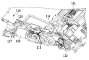
図1は本実施例に係る画像読取装置を備えた記録装置を示す斜視図である。記録装置1は、自動原稿搬送部(ADF部)100と、フラットベッドスキャナ(FBスキャナ)200と、インクジェット画像記録部3と、を含んで構成される。なお、本発明の適用はこの形態に限られず、例えば、上記構成において、インクジェット画像記録部3を含まない構成であってもよい。以下、FBスキャナなどを含む記録装置は画像読取装置ともいう。本実施例の画像読取装置1は、ユーザからの指示を受け付ける操作部2も含む。操作部2は、ユーザから原稿読取開始を指示するためのスタートキーや、自動原稿搬送読取(ADF読取)またはフラットベッド読取(FB読取)のいずれかを設定するためのカーソルキーなどを備えている。
Example 1
<Appearance of image reader>
FIG. 1 is a perspective view illustrating a recording apparatus including an image reading apparatus according to the present embodiment. The recording apparatus 1 includes an automatic document conveyance unit (ADF unit) 100, a flat bed scanner (FB scanner) 200, and an inkjet
図2は本実施例の記録装置において開閉可能なカバー部材を構成するADF部を開けた状態を示す斜視図である。ADF部100は、FBスキャナ200の上方において、左右のヒンジ115a、115bを介して一端を回動軸として開閉可能に設けられている。
FIG. 2 is a perspective view showing a state in which the ADF portion constituting the cover member that can be opened and closed is opened in the recording apparatus of the present embodiment. The
図3は本実施例に係るFBスキャナ200における読取ユニットの動作を説明するための図である。読取ユニット203は、図7にて後述されるように、その動作時には、自動原稿搬送透過部材(ADF透過部材)201およびフラットベッド透過部材(FB透過部材)202の下方に位置して移動可能に構成されている。これによりそれぞれの透過部材を介した読み取りをすることができる。
FIG. 3 is a diagram for explaining the operation of the reading unit in the
FB読取を行う場合に、ADF部100を開け、FB透過部材202の上に原稿を置き、ADF部100を閉じ、スタートキーを押す。その後、読取ユニット203(センサ部)は副走査方向に移動しながら静止した原稿をFB透過部材202を介して読取る(第1読取部での読み取りを行う)。
When performing FB reading, the
ADF読取を行う場合に、ADF部100を開けず、原稿をADF部100の給紙トレイ116にセットし、スタートキーを押す。その後、読取ユニット203は静止し、ADF部100(原稿搬送機構)は原稿を1枚ずつADF透過部材201に搬送する。読取ユニット203は搬送されてきた原稿をADF透過部材201を介して読み取り(第2読取部での読み取りを行い)、読取られた原稿はADF部100により排紙トレイ117に排紙される。
When performing ADF reading, the document is set on the
<画像読取装置の内部構成>
図4は、本実施例に係る画像読取装置の内部構成を示すブロック図である。画像読取装置1の内部には、ADF部100、FBスキャナ200、操作部2、制御部4、画像処理部5および記憶部6が含まれる。
<Internal configuration of image reading apparatus>
FIG. 4 is a block diagram illustrating an internal configuration of the image reading apparatus according to the present embodiment. The image reading apparatus 1 includes an
ADF部100は、制御部4に制御され、原稿を1枚ずつ給紙トレイ116からADF透過部材201に搬送し、さらに排紙トレイ117に搬送する。FBスキャナ200は、制御部4に制御され、原稿読取またはキャリブレーションのために読取ユニット203を駆動する。操作部2は、ユーザからの指示を受け付け、制御部4に送信する。制御部4は、操作部2からユーザの指示を受信し、画像読取装置1の各部の動作を制御する。画像処理部5は、読取画像に対し、例えばガンマ補正などの処理を行う。記憶部6は、制御部4の制御および他の各部の動作を実行するための各種プログラムを格納している。
The
また、FBスキャナ200の内部には、LED光源212およびラインセンサ213を有する読取ユニット203と、DCモータおよびエンコーダを有する読取ユニット駆動機構214とが含まれる。以下、FBスキャナ200の内部を詳細に説明する。
The
<FBスキャナ>
図4に示すように、読取ユニット203は、原稿に光を照射するLED光源212と、原稿の短手方向または長手方向の幅を読み取ることができるラインセンサ213とを有する。読取ユニット203をラインセンサ213の方向に対して直角に走査することで、原稿を読み取ることができる。ラインセンサ213の方向を主走査方向とし、読取ユニット203の移動する方向を副走査方向とする。読取ユニット203は等倍光学系を用いており、コンタクトイメージセンサ(CIS)と呼ばれる。
<FB scanner>
As shown in FIG. 4, the
読取ユニット駆動機構214は、制御部4によって制御され、読取ユニット203を副走査方向に移動させる。図3には、読取ユニット駆動機構214の上部における、スキャナベース204、ラック205およびガイドレール206が示される。図5は、読取ユニット駆動機構214の内部を示す斜視図である。以下、図3と図5を参照して読取ユニット駆動機構214の詳細を説明する。
The reading
読取ユニット駆動機構214は、読取ユニット203の駆動源としているDCモータ207を有する。DCモータ207の回転軸にはウォーム215が圧入されている。DCモータ207の回転は駆動列を介して駆動ギヤ210を回転させ、スキャナベース204に一体形成されているラック205に駆動力を伝える。スライダ211がガイドレール206に沿って滑ることで読取ユニット203を副走査方向に移動させる。
The reading
また、読取ユニット駆動機構214は、DCモータ207の回転を制御するために、回転量または変位量に応じてパルス信号を出力するエンコーダ209をさらに有する。エンコーダ209からのパルス信号に基づいてパルス幅変調(PWM)制御でDCモータ207の制御が行なわれる。
The reading
具体的には、DCモータ207の駆動制御のために、DCモータ207の回転軸にコードホイール208が圧入されている。コードホイールとはフィルム状の円盤に放射状に等間隔な線が印刷されてあるもので、エンコーダで等間隔な線の有無を読み取ることで、コードホイールの回転量を検出するための部材である。コードホイール208の読取に適した位置にエンコーダ209が取り付けられている。エンコーダ209は、コードホイール208に印刷されている等間隔な線を読取ることにより、DCモータ207の回転量を検出することができる。エンコーダ209の検出結果は、制御部4で処理され、DCモータ207への印加量が決定される。このことにより、DCモータ207の回転は所望の速度と位置に調整される。
Specifically, the
また、エンコーダ209の検出結果は、FB読取の場合の読取ユニット203の読取タイミング信号生成にも使用される。具体的には、制御部4は、エンコーダ209の検出結果に基づいて読取ユニット203の位置を算出し、算出した読取ユニット203の位置に応じて読取ユニット203の読取タイミング信号を生成する。このことにより、読取ユニット203が副走査方向に移動しながら原稿を読取る際に読取ユニット203の位置と読取タイミングを同期することで、読取位置のずれの発生を減少させることができる。
The detection result of the
一方、ADF読取の場合の読取ユニット203の読取タイミング信号生成には、エンコーダ209の検出結果ではなく、後述のエンコーダ111の検出結果が使用される。ADF読取の場合には、FB読取の場合と共通の読取ユニット203で原稿の読取を行うが、ADF読取の場合の読取ユニット203は、読取ユニット駆動機構214の駆動により所定位置に移動して静止し、ADF部で搬送されてきた原稿を読取る。そのため、搬送中の原稿の位置と読取タイミングを同期するために、搬送中の原稿の位置の算出を可能にするエンコーダ111の検出結果が使用される。
On the other hand, the detection result of the
<ADF部>
以下、ADF部100の詳細を説明する。図6は、ADF部100の内部を示す斜視図である。図7は、FBスキャナ200およびADF部100を読取副走査方向に切断した断面図である。
<ADF part>
Details of the
ADF部100は、原稿搬送の駆動源としているDCモータ109を有する。DCモータ109の駆動力は、駆動列により、ピックアップローラ101、分離ローラ102、搬送ローラ104、排紙ローラ106に伝えられる。給紙トレイ116にセットされた原稿はピックアップローラ101と分離ローラ102の回転により、1枚ずつ分離された状態で、搬送ローラ104と搬送従動ローラ105に狭持され、搬送ローラ104の回転により、ADF透過部材201に搬送される。そして、バネ付勢された白地板108によって原稿はADF透過部材201に密着し、読取ユニット203によって、原稿が読み取られる。さらにDCモータ109を駆動することで、原稿は排紙ローラ106と排紙従動ローラ107に狭持され、排紙ローラ106の回転により、原稿は排紙トレイ117に排出される。
The
また、ADF部100は、DCモータ109の回転を制御するために、回転量または変位量に応じてパルス信号を出力するエンコーダ111をさらに有する。エンコーダ111からのパルス信号に基づいてパルス幅変調(PWM)制御でDCモータ109の制御が行なわれる。
The
具体的には、DCモータ109の駆動制御のために、DCモータ109の回転軸にコードホイール110が圧入されている。コードホイール110の読取に適した位置にエンコーダ111が取り付けられている。エンコーダ111は、コードホイール110に印刷されている等間隔な線を読取ることにより、DCモータ109の回転量を検出することができる。エンコーダ111の検出結果は、制御部4で処理され、DCモータ109への印加量が決定される。このことにより、DCモータ109は所望の速度と位置に調整される。
Specifically, the
また、エンコーダ111の検出結果は、ADF読取の場合の読取ユニット203の読取タイミング信号生成にも使用される。具体的には、制御部4は、エンコーダ111の検出結果に基づいて原稿の位置を算出し、算出した原稿の位置に応じて読取ユニット203の読取タイミング信号を生成する。このことにより、搬送された原稿の位置と読取タイミングを同期することで、読取位置のずれの発生を減少させることができる。
The detection result of the
<キャリブレーション処理>
本発明の一実施例は、FB読取りとADF読取りそれぞれで個別のキャリブレーションを行う形態に関する。具体的には、前述したように、FB読取りで用いるFB透過部材202と、ADF読取りで用いるADF透過部材201とを別の部材で構成する。そして、読取りユニット203によって、それぞれの透過部材を介して色基準シートの読取りを行う(色基準部を測定する)。その読取り結果(測定結果)に基づいて、FB読取りおよびADF読取りそれぞれにおける読取りユニットのキャリブレーションを行う。
<Calibration process>
One embodiment of the present invention relates to a form in which individual calibration is performed for each of FB reading and ADF reading. Specifically, as described above, the
次にFB透過部材202とADF透過部材201の詳細について説明する。図8は本実施例に係る画像読取装置のADF透過部材201とFB透過部材202近傍の断面図である。
Next, details of the
本実施例において、FB透過部材202の材質はガラスである。ADF透過部材201の材質は透明なAS樹脂(アクリロ二トリルスチレン樹脂)である。耐傷性を向上させるために、原稿と接触する面にはハードコーティングがなされている。また、ガラスとAS樹脂では屈折率が異なるため、読取ユニットの光学特性に合わせて、ADF透過部材201とFB透過部材202の厚みを調整することで、原稿の読取面に焦点が合うように設定されている。
In this embodiment, the material of the
ADF透過部材201を樹脂化するメリットとして、下記2点を挙げることができる。(1)比重が小さいことによる軽量化。装置重量が軽くなることにより、利用者による可搬性の向上や輸送コストの低減ができる。(2)熱可塑性が高くて、周辺部品との一体化による形状最適化。本実施例において、ADF透過部材201は、射出成型で製造され、ADF読取位置下流の原稿搬送方向Pを排紙方向へ変えるための傾斜部201aと一体形成されている。このように、ADF透過部材201と傾斜部201aを一体に形成することで、ADF透過部材201と傾斜部201aの境界を滑らかな曲面で形成することができる。その結果、原稿通過時に原稿の挙動乱れを低減することができ、画像品質が向上する。
The following two points can be cited as advantages of making the
なお、FB透過部材202とADF透過部材201はガラスとAS樹脂に限定されず、光線透過率が一定以上の材質であれば適用可能である。
The
上述したように、FB透過部材とADF透過部材が異なる材質で、色味が同一にならない。そこで、FB読取とADF読取それぞれにおいて原稿に忠実な色味で読取画像を得るように、FB読取とADF読取に関して、別々のキャリブレーション処理が行われる。 As described above, the FB transmissive member and the ADF transmissive member are made of different materials, and the colors are not the same. Therefore, separate calibration processing is performed for the FB reading and the ADF reading so that a read image is obtained with a color faithful to the original in each of the FB reading and the ADF reading.
本実施例のキャリブレーション処理は、色基準シート(シート状の部材)をキャリブレーション位置に設置し、読取ユニット203をキャリブレーション位置に移動させ、設置した色基準シートを読取らせることにより行われる。ここで、キャリブレーション位置は、キャリブレーションのための読取が行われる位置である。FB読取とADF読取に関して、別々のキャリブレーション処理を行うために、色基準シートを別々のキャリブレーション位置に設置する。図8に示すように、FBキャリブレーション位置303(第1位置)とADFキャリブレーション位置302(第2位置)は、互いに独立している。
The calibration process of this embodiment is performed by placing a color reference sheet (sheet-like member) at a calibration position, moving the
なお、本実施例において、色基準シートが設置されるキャリブレーション位置は、原稿が読取られる位置(原稿読取位置)と異なる。キャリブレーション位置と原稿読取位置とが同一である場合に比べて、キャリブレーションの際に色基準シートを置いたり、原稿読取の際に色基準シートを取り下げたりする必要がなくなる。また、ADF読取位置301とADFキャリブレーション位置302における、ADF透過部材201の厚みは同一である。それにより、ADFキャリブレーションとADF読取が同じ透過部材を介して行われることを確保することができる。FBキャリブレーション位置303とFB読取位置における、FB透過部材202の厚みは同一である。それにより、フラットベッドキャリブレーション(FBキャリブレーション)とFB読取が同じ透過部材を介して行われることを確保することができる。
In this embodiment, the calibration position where the color reference sheet is installed is different from the position where the document is read (document reading position). Compared to the case where the calibration position and the document reading position are the same, it is not necessary to place a color reference sheet during calibration or to remove the color reference sheet during document reading. The thickness of the
また、図8には、本実施例のキャリブレーション処理に使用される色基準シート118も示されている。色基準シート118は、色味が既知である、または色味のばらつき範囲が既知である樹脂製シートで形成されている。図8に示すように、FBキャリブレーション位置303の色基準シート(第1位置における色基準部)とADFキャリブレーション位置302の色基準シート(第2位置における色基準部)は一体で形成されている。それにより、FBキャリブレーションの色基準シートとADFキャリブレーションの色基準シートの色味がばらつきの影響を受けずに略同一にすることができる。ここで、FBキャリブレーションの色基準シートとADFキャリブレーションの色基準シートは一体で形成されていることが説明されたが、これに限らず、同じ色基準を持てばよい。
FIG. 8 also shows a
なお、本実施例のように、ADF透過部材201と傾斜部201aが一体形成されている場合、色基準シート118の上面が透過部材であるため、キャリブレーションが外光の影響を受ける可能性がある。外光の影響を小さくするために、色基準シート118の裏面に黒色印刷をしてもよい。
If the
<画像読取装置の処理フロー>
次に本実施例の画像読取装置の処理フローについて説明する。図9は本実施例の画像読取装置の処理を説明したフローチャートである。
<Processing flow of image reading apparatus>
Next, the processing flow of the image reading apparatus of this embodiment will be described. FIG. 9 is a flowchart illustrating the processing of the image reading apparatus according to the present exemplary embodiment.
ステップS401において、制御部4は、原稿の読取開始を指示するための読み取り命令を操作部2から受信する。
In step S <b> 401, the control unit 4 receives a reading command for instructing the start of reading of the document from the
ステップS402において、制御部4は、読取モードがFB読取またはADF読取のいずれかを判定する。読取モードは、操作部2から読取モードに関するユーザ設定を受信することにより判定することができる。あるいは、ADFの給紙トレイ116に原稿がセットされていることをセンサで検知して、原稿ありの場合にADF読取、原稿なしの場合にFB読取となるように読取モードを判定することもできる。ステップS402でFB読取であると判定した場合に、フローはステップS451に進み、FB読取を行う。一方、ステップS402でADF読取であると判定した場合に、フローはステップS403に進み、ADF読取を行う。
In step S402, the control unit 4 determines whether the reading mode is FB reading or ADF reading. The reading mode can be determined by receiving user settings regarding the reading mode from the
ステップS451において、読取ユニット駆動機構214は、読取ユニット203をFBキャリブレーション位置303に移動させる。
In step S451, the reading
ステップS452において、FB読取用のキャリブレーションが行われる。読取ユニット203は、FBキャリブレーション位置303においてFB透過部材202を介して色基準シート118の読み取りを行い、FB透過部材202の色味の影響を含んだ読取データを取得する。制御部4は、FB透過部材202の色味の影響を含んだ読取データ読取データを用いてキャリブレーション処理を行う。それにより、FB透過部材202の色味の影響を考慮した読取ユニット203のキャリブレーションが可能である。
In step S452, calibration for FB reading is performed. The
以下、FB読取用のキャリブレーションの詳細を説明する。まず、読取ユニット203の光源であるLED光源212(照明手段)の特性ばらつきを補正する。FBスキャナ200は、LED光源212の出力または時間を段階的に変更して発光させ、色基準シート118からの反射光をラインセンサ213で読み取り、適切な光量が得られるように、LED光源212の出力または時間を調節する。次に、読取ユニット203のラインセンサ213(撮像手段)の特性(感度)ばらつきを補正する。FBスキャナ200は、適切な光量でLED光源212を発光させたときにラインセンサ213の出力を白基準データとして、LED光源212を消灯したときのラインセンサ213の出力を黒基準データとする。これら2点データを基準にあらかじめ設定されたトーンカーブを用いて補間しラインセンサ213の出力が主走査方向に正確かつ均一になるように調節する。
Details of calibration for FB reading will be described below. First, the characteristic variation of the LED light source 212 (illuminating means) that is the light source of the
なお、色基準シート118の表面状態に起因する色味のばらつきを平均化するために、読取ユニット203を移動しながら複数回読取データを取得し、平均化した読取データを用いてキャリブレーション処理を行うこともできる。
In addition, in order to average the variation in color caused by the surface state of the
その後、ステップS453およびステップS454において、FB読取が行われる。ステップS453では読取モードによって決定された速度で読取ユニット203を副走査方向に駆動すると同時にステップS454で読取ユニット203を用いて決められた範囲の画像読取を行う。読取完了後、フローはステップS455に進む。
Thereafter, FB reading is performed in steps S453 and S454. In step S453, the
ステップS455において、読取ユニット駆動機構214は、読取ユニット203を待機位置まで移動させて、読取動作を完了する。
In step S455, the reading
一方、ステップS402でADF読取であると判定した場合に、フローはステップS403に進む。ステップS403において、読取ユニット駆動機構214は、読取ユニット203をADFキャリブレーション位置302に移動させる。
On the other hand, when it is determined in step S402 that ADF reading is performed, the flow proceeds to step S403. In step S <b> 403, the reading
ステップS404において、ADF読取用のキャリブレーションが行われる。読取ユニット203は、ADFキャリブレーション位置302においてADF透過部材201を介して色基準シート118の読み取りを行い、ADF透過部材201の色味の影響を含んだ読取データを取得する。制御部4は、ADF透過部材201の色味の影響を含んだ読取データを用いてキャリブレーション処理を行う。それにより、ADF透過部材201の色味の影響を考慮した読取ユニット203のキャリブレーションが可能である。ADF読取用のキャリブレーション処理の詳細はFB読取用のキャリブレーション処理と同様であるので、省略する。
In step S404, calibration for ADF reading is performed. The
その後、ステップS405において、読取ユニット駆動機構214は、読取ユニット203をADF読取位置301に移動させる。
Thereafter, in step S <b> 405, the reading
そして、ステップS406、ステップS407およびステップS408において、ADF読取が行われる。ステップS406では読取モードによって決定された速度で原稿を搬送すると同時にステップS407で画像読取を行う。1枚の原稿を読取完了した後、ステップS408で次の原稿があると判定した場合はステップS406とステップS407を繰り返し、ステップS408で次の原稿がないと判定した場合に、フローはステップS409に進む。 In step S406, step S407, and step S408, ADF reading is performed. In step S406, the document is conveyed at the speed determined by the reading mode, and at the same time, the image is read in step S407. After completing the reading of one original, if it is determined in step S408 that there is a next original, step S406 and step S407 are repeated. If it is determined in step S408 that there is no next original, the flow proceeds to step S409. move on.
ステップS409において、読取ユニット駆動機構214は、読取ユニット203を待機位置に移動させて、読取動作を完了する。
In step S409, the reading
以上のことにより、FB読取とADF読取のためにそれぞれの透過部材を通して、互いに独立しているキャリブレーションを行うことができるので、FB読取とADF読取それぞれにおいて、対象原稿に忠実な色味で読取画像を得ることができる。また、同じ原稿を読み取ったときに、FB読取画像とADF読取画像の色味の差異を低減することができる。 As described above, since calibration independent from each other can be performed through the respective transparent members for FB reading and ADF reading, each of the FB reading and the ADF reading is read with a color faithful to the target document. An image can be obtained. Further, when the same document is read, the difference in color between the FB read image and the ADF read image can be reduced.
なお、本実施例ではFB透過部材をガラス、ADF透過部材をAS樹脂としたが、本発明の効果はこの組み合わせに限定されるものではない。たとえばFB透過部材とADF透過部材が共にガラスの組み合わせであっても、製造メーカ、製造時期、経年、厚みなどの差異により完全に同一の色味となることはない。このことからFB透過部材とADF透過部材の材質が同じであっても、また異なっていても本発明の効果を得ることができる。換言すれば、ADF透過部材とFB透過部材は、別の部材(異なる部材)であれば本発明を適用することができる。ここで、「別の部材(異なる部材)」とは、材質が異なるものと、物理的に離れたものとを含む。 In this embodiment, the FB transmitting member is made of glass and the ADF transmitting member is made of AS resin. However, the effect of the present invention is not limited to this combination. For example, even if the FB transmissive member and the ADF transmissive member are both a combination of glass, they do not have the same color due to differences in manufacturer, production time, age, thickness, and the like. Therefore, the effects of the present invention can be obtained even if the materials of the FB transmitting member and the ADF transmitting member are the same or different. In other words, the present invention can be applied if the ADF transmission member and the FB transmission member are different members (different members). Here, “another member (different member)” includes a different material and a physically separated member.
(実施例2)
実施例1の構成に加え、ADF部100により搬送されてきた原稿の裏面を読み取るための裏面読取ユニットを備えた実施例2について説明する。なお、実施例1と同じ構成および処理については説明を省略する。
(Example 2)
In addition to the configuration of the first embodiment, a second embodiment provided with a back surface reading unit for reading the back surface of the document conveyed by the
図10は、本実施例に係る画像読取装置の内部構成を示すブロック図である。本実施例の画像読取装置の内部構成は実施例1の画像読取装置1と同様であるが、裏面読取ユニット119(裏面センサ部)をさらに含む。 FIG. 10 is a block diagram illustrating an internal configuration of the image reading apparatus according to the present embodiment. The internal configuration of the image reading apparatus according to the present embodiment is the same as that of the image reading apparatus 1 according to the first embodiment, but further includes a back surface reading unit 119 (back surface sensor unit).
図11は、本実施例のFBスキャナ200、ADF部100、読取ユニット203および裏面読取ユニット119を読取副走査方向に切断した断面図である。図11に示すように、読取ユニット203の原稿搬送方向下流に裏面読取ユニット119がある。本実施例において、読取ユニット203は原稿搬送経路の下方にあり、搬送されてきた原稿の表面をADF透過部材201を介して読取ることができる。裏面読取ユニット119は原稿搬送経路の上方にあり、搬送されてきた原稿の裏面を裏面ADF透過部材123を介して読み取る(第3読取部での読み取りを行う)ことができる。裏面読取ユニット119は、裏面LED光源120と裏面ラインセンサ121とを有し、読取ユニット203と同様に等倍光学系のコンタクトイメージセンサ(CIS)を用いている。
FIG. 11 is a cross-sectional view of the
また、裏面読取ユニット119(裏面CIS)の読取タイミング信号生成は、ADF読取の場合の読取ユニット203の読取タイミング信号生成と同様に、エンコーダ111の信号を使用する。すなわち、制御部4は、エンコーダ111によって検出されたDCモータ109の回転量に基づいて原稿の位置を算出し、算出した原稿の位置に応じて裏面読取ユニット119の読取タイミング信号を生成する。このことにより、搬送された原稿の位置と読取タイミングを同期することで、読取位置のずれの発生を減少させることができる。
In addition, the reading timing signal generation of the back side reading unit 119 (back side CIS) uses the signal of the
本実施例において、FB透過部材202と、ADF透過部材201と、裏面ADF透過部材123とは別の部材で構成され、色味が異なっている。原稿に忠実な色味で読取画像を得るように、FB読取と、ADF読取と、裏面ADF読取とに関して、別々のキャリブレーション処理が必要となっている。
In the present embodiment, the
図12は本実施例に係る画像読取装置のADF透過部材201、裏面ADF透過部材123とFB透過部材202近傍の断面図である。実施例1に対して、異なっている点は、ADF透過部材の傾斜部201aと原稿台フレーム216の間にも、裏面ADF読取のための色基準シート(色基準シート118’)が入るように構成されている。また、FBキャリブレーション位置303の色基準シートとADFキャリブレーション位置302の色基準シート、裏面ADFキャリブレーション位置304(第3位置)の色基準シート(第3位置における色基準部)は一体で形成されている。それにより、FBキャリブレーションの色基準シートとADFキャリブレーションの色基準シート、裏面ADFキャリブレーションの色基準シートの色味がばらつきの影響を受けずに略同一にすることができる。
FIG. 12 is a cross-sectional view of the vicinity of the
FB読取用のキャリブレーション処理およびADF読取用のキャリブレーション処理は実施例1と同様であるので、それについての記載を省略する。以下、裏面ADF読取用のキャリブレーション(裏面読取ユニットキャリブレーション)処理の詳細について説明する。 Since the calibration process for FB reading and the calibration process for ADF reading are the same as those in the first embodiment, description thereof is omitted. Details of the calibration for the back surface ADF reading (back surface reading unit calibration) will be described below.
本実施例において、裏面ADF読取と、裏面ADF読取用のキャリブレーションとは、同じ位置において行われる。すなわち、裏面ADF読取位置と、裏面ADFキャリブレーション位置304とは同一のものである。そのため、裏面ADF読取用のキャリブレーションおよび裏面ADF読取の前に、裏面読取ユニット119を移動させる必要がなく、裏面読取ユニット119を裏面ADFキャリブレーション位置304に設置すればよい。
In this embodiment, the back surface ADF reading and the calibration for the back surface ADF reading are performed at the same position. That is, the back ADF reading position and the back
裏面ADFキャリブレーションの場合に、裏面読取ユニット119は、裏面ADFキャリブレーション位置304において裏面ADF透過部材123および色基準シート118’にかぶさっている傾斜部201aを介して色基準シート118’の読取を行う。この読取により、裏面ADF透過部材123および傾斜部201aの色味の影響を含んだ読取データを取得する。一方、裏面読取ユニット処理裏面ADF読取の場合に、裏面読取ユニット119は、搬送されてきた原稿を裏面ADF透過部材123を介して読取る。裏面ADF透過部材123および傾斜部201aの色味の影響を含んだ読取データを用いて裏面ADF読取用のキャリブレーション処理を行えば、傾斜部201aの色味の影響が原因で、裏面ADF読取に適切な色補正を実現することができない。
In the case of the back surface ADF calibration, the back
本実施例において、制御部4は、予め傾斜部201aの色味のデータを取得し、保持している。制御部4は、裏面読取ユニット119に読取られた裏面ADF透過部材123および傾斜部201aの色味の影響を含んだ読取データと、保持している傾斜部201aの色味のデータとを用いて、裏面ADF読取用のキャリブレーション処理を行う。
In the present embodiment, the control unit 4 acquires and holds the color data of the
なお、傾斜部201aの色味のデータは以下の手法で定期的に取得または更新することができる。とくに、装置が長期間使用されていなかった場合に用いることが好ましい。傾斜部201aに対向している裏面ADFキャリブレーション位置304において色基準シート118’の読取を行い、裏面ADF透過部材123および傾斜部201aの色味の影響を含んだ読取データA+Bを取得する。このとき、読取ユニット203をADFキャリブレーション位置302に移動させ、ADF透過部材201の色味の影響を含んだ読取データCも同時に取得しておく。その後、表裏の色味が同一の白紙を通紙させ、読取ユニット203により白紙の表面データC+αを取得し、裏面読取ユニット119により白紙の裏面データA+αを取得する。読取ったデータを取得した後に、まずは同一の読取ユニット203とADF透過部材201とから取得した読取データCと読取データC+αとの差分からデータαを算出する。これによって、色基準シート118’と白紙との色味による差分がデータαとして明らかになる。そして、読取データA+αとデータαとの差分から、裏面ADF透過部材123の色味の影響を含んだデータAを算出する。さらに、読取データA+BおよびデータAとの差分から、傾斜部201aの色味のデータBを算出することができる。このように、上記の手法によって取得または更新された傾斜部201aの色味のデータを用いることによって、裏面読取ユニット119が原稿の色味に忠実な読取画像を取得できる。なお、本例は説明を概念化するために簡易的な計算例を示したに過ぎない。したがって、係数を乗じるなど複雑な計算式によって、より最適なデータを取得してもよい。
Note that the color data of the
次に本実施例の画像読取装置の処理フローについて説明する。図13は本実施例の画像読取装置の処理を説明したフローチャートである。FB読取および表面ADF読取のときの画像読取動作は実施例1と同様である。両面ADF読取の場合のみを説明する。 Next, the processing flow of the image reading apparatus of this embodiment will be described. FIG. 13 is a flowchart for explaining the processing of the image reading apparatus of this embodiment. The image reading operation at the time of FB reading and front surface ADF reading is the same as that of the first embodiment. Only the case of double-sided ADF reading will be described.
ADF両面読取が設定されている場合には、ステップS412において制御部4はADFの両面読取であると判定する。 If ADF double-sided scanning is set, the control unit 4 determines in step S412 that it is ADF double-sided scanning.
ステップS422において、読取ユニット駆動機構214は、読取ユニット203をADFキャリブレーション位置302に移動させる。
In step S <b> 422, the reading
ステップS423において、表面ADF読取用のキャリブレーションが行われる。本ステップのADF読取用のキャリブレーション処理はステップS404の処理と同様であるので、それについての説明を省略する。 In step S423, calibration for surface ADF reading is performed. Since the calibration process for ADF reading in this step is the same as the process in step S404, description thereof is omitted.
さらにステップS424において、裏面ADF読取用のキャリブレーションが行われる。裏面読取ユニット119は、裏面ADFキャリブレーション位置304において裏面ADF透過部材123および傾斜部201aを介して色基準シート118’の読み取りを行う。裏面ADF透過部材123および傾斜部201aの色味の影響を含んだ読取データを取得する。制御部4は、裏面ADF透過部材123および傾斜部201aの色味の影響を含んだ読取データと予め保持している傾斜部201aの色味のデータとを用いてキャリブレーション処理を行う。それにより、裏面ADF透過部材123および傾斜部201aの色味の影響を考慮した裏面読取ユニット119のキャリブレーションが可能である。
Further, in step S424, calibration for reading back ADF is performed. The back
その後、ステップS425において、読取ユニット駆動機構214は読取ユニット203を表面ADF読取位置301に移動させる。
Thereafter, in step S425, the reading
そして、ステップS426からステップS429において、表面ADF読取および裏面ADF読取が行われる。ステップS426では読取モードによって決定された速度で原稿を搬送すると同時にステップS427で表面原稿読取とステップS428で裏面原稿読取を行う。1枚の原稿を読取完了した後、ステップS408で次の原稿があると判定した場合はステップS406とステップS407を繰り返し、ステップS408で次の原稿がないと判定した場合に、フローはステップS409に進む。1枚の原稿を読取完了した後、ステップS429で次の原稿があると判定した場合はステップS426とステップS427、およびステップS428を繰り返し、ステップS429で次の原稿がないと判定した場合に、フローはステップS430に進む。 Then, from step S426 to step S429, front side ADF reading and back side ADF reading are performed. In step S426, the original is conveyed at a speed determined by the reading mode, and at the same time, the front side original is read in step S427 and the back side original is read in step S428. After completing the reading of one original, if it is determined in step S408 that there is a next original, step S406 and step S407 are repeated. If it is determined in step S408 that there is no next original, the flow proceeds to step S409. move on. After reading one document, if it is determined in step S429 that there is a next document, step S426, step S427, and step S428 are repeated, and if it is determined in step S429 that there is no next document, the flow Advances to step S430.
ステップS430において、読取ユニット駆動機構214は読取ユニット203を待機位置に移動させて、読取動作を完了する。
In step S430, the reading
以上のことにより、FB読取、表面ADF読取および裏面ADF読取のためにそれぞれの透過部材を通して、キャリブレーションを行うことができるので、同じ原稿を読み取ったときに、FB読取画像とADF読取画像の色味の差異を低減することができる。また、裏面ADF読取画像と表面ADF読取画像の色味の差異を低減することもできる。 As described above, since calibration can be performed through each transparent member for FB reading, front surface ADF reading, and back surface ADF reading, the colors of the FB read image and the ADF read image can be obtained when the same document is read. The difference in taste can be reduced. In addition, the difference in color between the back ADF read image and the front ADF read image can be reduced.
なお、本実施例において、裏面ADF読取用のキャリブレーションには、予め保持している傾斜部201aの色味のデータを用いたが、傾斜部201aの色味の影響をなくすことができれば、他の方法を使用してもかまわない。例えば、裏面ADFキャリブレーション位置304に応じて、傾斜部201aに矩形の穴を作る。それによって、裏面ADFキャリブレーションの場合に、裏面読取ユニット119は、裏面ADFキャリブレーション位置304において裏面ADF透過部材123のみを介して色基準シート118’の読取を行うことができる。このように、裏面ADF透過部材123の色味の影響を含んだが傾斜部201aの色味の影響を含まない読取データが取得される。制御部4は、取得された読取データを用いて裏面ADF読取用のキャリブレーション処理を行うことができる。
In this embodiment, the color data of the
(その他の実施例)
また、本発明は、以下の処理を実行することによっても実現される。即ち、上述した実施形態の機能を実現するソフトウェア(プログラム)を、ネットワーク又は各種記憶媒体を介してシステム或いは装置に供給し、そのシステム或いは装置のコンピュータ(またはCPUやMPU等)がプログラムを読み出して実行する処理である。
(Other examples)
The present invention can also be realized by executing the following processing. That is, software (program) that realizes the functions of the above-described embodiments is supplied to a system or apparatus via a network or various storage media, and a computer (or CPU, MPU, or the like) of the system or apparatus reads the program. It is a process to be executed.
1・・・・・記録装置
3・・・・・画像記録部
4・・・・・制御部
100・・・自動原稿搬送部(ADF部)
118・・・色基準シート
119・・・裏面読取ユニット(裏面CIS)
123・・・裏面ADF透過部材
200・・・フラットベッドスキャナ(FBスキャナ)
201・・・ADF透過部材
201a・・傾斜部
202・・・FB透過部材
203・・・読取ユニット(CIS)
216・・・原稿台フレーム
301・・・ADF読取位置および表面ADF読取位置
302・・・ADFキャリブレーション位置および表面キャリブレーション位置
303・・・FBキャリブレーション位置
304・・・裏面ADF読取位置および裏面ADFキャリブレーション位置
P・・・・・原稿通紙方向
DESCRIPTION OF SYMBOLS 1 ...
100 ... Automatic document feeder (ADF section)
118 ...
123... ADF transmissive member on the back surface
200 ... Flatbed scanner (FB scanner)
201...
216 ... Platen frame
301... ADF reading position and front surface
P: Document feeding direction
Claims (13)
第1透過部材を備え、前記第1透過部材の上に置かれた原稿を前記センサ部を移動させながら下方から読取る第1読取部と、
前記第1透過部材とは異なる第2透過部材を備え、前記第2透過部材の上を搬送される原稿を静止した前記センサ部により下方から読取る第2読取部と、
色基準部と
を有し、
前記第1読取部での読み取りのキャリブレーションのために第1位置において前記第1透過部材を介して前記センサ部により行われる前記色基準部の測定と、前記第2読取部での読み取りのキャリブレーションのために前記第1位置とは異なる第2位置において前記第2透過部材を介して前記センサ部により行われる前記色基準部の測定と、が可能であって、
前記色基準部においては、1枚の白色シートが、前記第1位置にて前記第1透過部材の上面を覆うとともに前記第2位置にて前記第2透過部材の上面を覆っていることを特徴とする画像読取装置。 A sensor unit;
A first reading unit that includes a first transmission member, and reads a document placed on the first transmission member from below while moving the sensor unit;
A second reading unit that includes a second transmitting member different from the first transmitting member, and reads a document conveyed on the second transmitting member from below by the stationary sensor unit;
A color reference part,
The measurement of the color reference unit performed by the sensor unit via the first transmission member in the first position for the calibration of reading by the first reading unit, and the calibration of reading by the second reading unit , the measurement of the color reference portion performed by the sensor unit via the second transmitting member in a second position different from said first position for Deployment a possible,
In the color reference portion, one white sheet covers the upper surface of the first transmission member at the first position and covers the upper surface of the second transmission member at the second position. An image reading apparatus.
前記第2読取部での読み取りが行われる位置と、前記第2位置とは異なることを特徴とする請求項1または2に記載の画像読取装置。 The position where reading by the first reading unit is performed is different from the first position,
The image reading apparatus according to claim 1 or 2, characterized the position of reading in the second scanning unit is carried out, different from the said second position.
前記第2読取部での読み取りが行われる位置と、前記第2位置とにおいて、前記第2透過部材の厚みが同一であることを特徴とする請求項3に記載の画像読取装置。 The thickness of the first transmission member is the same at the position where the reading by the first reading unit is performed and the first position,
The image reading apparatus according to claim 3 , wherein the second transmission member has the same thickness at a position where reading by the second reading unit is performed and at the second position.
前記第2透過部材は、前記第2読取部での読み取りが行われる位置の下流の原稿搬送方向を排紙方向へ変えるための、傾斜部と一体で形成されていることを特徴とする請求項1から5のいずれか1項に記載の画像読取装置。 The second reading unit reads the document conveyed to the second transmission member by the document conveying mechanism by the sensor unit,
The second transmissive member is formed integrally with an inclined portion for changing a document conveying direction downstream of a position where reading is performed by the second reading portion to a paper discharge direction. The image reading apparatus according to any one of 1 to 5 .
前記第1透過部材および前記第2透過部材とは異なる第3透過部材を介して、前記裏面センサ部により原稿の裏面を読取る第3読取部と
をさらに有し、
前記第3読取部での読み取りのキャリブレーションのために、前記裏面センサ部により前記色基準部を測定するように制御されることを特徴とする請求項1から6のいずれか1項に記載の画像読取装置。 A back sensor part;
A third reading unit for reading the back side of the document by the back side sensor unit via a third transmitting member different from the first transmitting member and the second transmitting member;
For reading the calibration in the third reading unit, by the rear surface sensor unit as claimed in any one of claims 1 to 6, wherein the controlled is possible to measure the color reference portion Image reading device.
前記第3位置は、前記第2読取部での読み取りが行われる位置の下流の原稿搬送方向を排紙方向へ変えるための、傾斜部に対向しており、
前記第3位置における前記色基準部と前記第3透過部材は、前記傾斜部を挟んで向かい合うことを特徴とする請求項8に記載の画像読取装置。 The second reading unit reads, by the sensor unit, the surface of the document that has been transported to the second transmission member by the document transport mechanism,
The third position is opposed to an inclined portion for changing the document transport direction downstream of the position where reading by the second reading unit is performed to the paper discharge direction,
The image reading apparatus according to claim 8 , wherein the color reference portion and the third transmission member at the third position face each other with the inclined portion interposed therebetween.
前記第3読取部での読み取りのキャリブレーションは、前記第3位置において前記第3透過部材を介して前記色基準部を測定することにより得たデータに基づいて行われることを特徴とする請求項9に記載の画像読取装置。 According to the third position, a hole is formed in the inclined portion,
The calibration of reading by the third reading unit is performed based on data obtained by measuring the color reference unit via the third transmitting member at the third position. The image reading apparatus according to 9 .
Priority Applications (3)
| Application Number | Priority Date | Filing Date | Title |
|---|---|---|---|
| JP2013173385A JP6257219B2 (en) | 2013-08-23 | 2013-08-23 | Image reading device |
| US14/338,901 US9124747B2 (en) | 2013-08-23 | 2014-07-23 | Image reading device and image reading method |
| CN201410418910.1A CN104427207B (en) | 2013-08-23 | 2014-08-22 | Image read-out and image reading method |
Applications Claiming Priority (1)
| Application Number | Priority Date | Filing Date | Title |
|---|---|---|---|
| JP2013173385A JP6257219B2 (en) | 2013-08-23 | 2013-08-23 | Image reading device |
Publications (2)
| Publication Number | Publication Date |
|---|---|
| JP2015041965A JP2015041965A (en) | 2015-03-02 |
| JP6257219B2 true JP6257219B2 (en) | 2018-01-10 |
Family
ID=52480138
Family Applications (1)
| Application Number | Title | Priority Date | Filing Date |
|---|---|---|---|
| JP2013173385A Expired - Fee Related JP6257219B2 (en) | 2013-08-23 | 2013-08-23 | Image reading device |
Country Status (3)
| Country | Link |
|---|---|
| US (1) | US9124747B2 (en) |
| JP (1) | JP6257219B2 (en) |
| CN (1) | CN104427207B (en) |
Families Citing this family (7)
| Publication number | Priority date | Publication date | Assignee | Title |
|---|---|---|---|---|
| JP5990093B2 (en) | 2012-11-29 | 2016-09-07 | キヤノン株式会社 | Image processing apparatus, image processing method, and program |
| JP6410523B2 (en) * | 2014-08-22 | 2018-10-24 | キヤノン株式会社 | Image reading device |
| US9571690B2 (en) * | 2015-03-19 | 2017-02-14 | Ricoh Company, Ltd. | Image scanner and image forming apparatus incorporating the image scanner |
| JP6500714B2 (en) * | 2015-09-08 | 2019-04-17 | セイコーエプソン株式会社 | Reader |
| JP2017112522A (en) * | 2015-12-17 | 2017-06-22 | 富士ゼロックス株式会社 | Image forming apparatus and control program |
| WO2019176051A1 (en) | 2018-03-15 | 2019-09-19 | オリンパス株式会社 | Observation device |
| CN111209830B (en) * | 2019-12-31 | 2023-04-14 | 深圳市中福信息科技有限公司 | Face recognition method and face recognition camera |
Family Cites Families (22)
| Publication number | Priority date | Publication date | Assignee | Title |
|---|---|---|---|---|
| US4739414A (en) * | 1986-07-15 | 1988-04-19 | Ovonic Imaging Systems, Inc. | Large area array of thin film photosensitive elements for image detection |
| JPH0322751A (en) * | 1989-06-20 | 1991-01-31 | Toshiba Corp | Reader |
| US5579129A (en) * | 1993-12-17 | 1996-11-26 | Canon Kabushiki Kaisha | Original reading apparatus and information processing apparatus with original reading apparatus |
| JP3410190B2 (en) * | 1993-12-29 | 2003-05-26 | 株式会社東芝 | Image forming apparatus and document reading method |
| JP3440897B2 (en) * | 1999-09-17 | 2003-08-25 | ミノルタ株式会社 | Image determination device and image forming device |
| US7031515B2 (en) * | 2002-07-19 | 2006-04-18 | Kabushiki Kaisha Toshiba | Image processing apparatus and image processing method |
| JP2004349911A (en) * | 2003-05-21 | 2004-12-09 | Ricoh Co Ltd | Automatic draft feeder and image forming apparatus employing the same |
| JP4305193B2 (en) * | 2004-01-23 | 2009-07-29 | 富士ゼロックス株式会社 | Image reading device |
| US7557969B2 (en) * | 2004-03-22 | 2009-07-07 | Kabushiki Kaisha Toshiba | Color balance correction chart, color balance correction method, and image forming apparatus |
| JP4442272B2 (en) * | 2004-03-22 | 2010-03-31 | 富士ゼロックス株式会社 | Image reading device and foreign material detection method for reference member |
| JP4567416B2 (en) * | 2004-10-29 | 2010-10-20 | 株式会社セイコーアイ・インフォテック | Document reading method, document reading apparatus, image forming apparatus, and image scanner |
| JP4235608B2 (en) * | 2004-12-24 | 2009-03-11 | キヤノン株式会社 | Image reading device |
| JP2008005360A (en) * | 2006-06-23 | 2008-01-10 | Canon Inc | Image reader |
| JP4888139B2 (en) * | 2007-01-31 | 2012-02-29 | ブラザー工業株式会社 | Image reading device |
| JP4948291B2 (en) * | 2007-06-29 | 2012-06-06 | キヤノン株式会社 | Document reader |
| JP4853403B2 (en) * | 2007-07-02 | 2012-01-11 | セイコーエプソン株式会社 | Image reading device |
| US8203750B2 (en) * | 2007-08-01 | 2012-06-19 | Xerox Corporation | Color job reprint set-up for a printing system |
| CN102326377B (en) * | 2009-05-01 | 2014-06-04 | 佳能组件股份有限公司 | Image reading device, and image forming device and method |
| JP2011071690A (en) * | 2009-09-25 | 2011-04-07 | Nisca Corp | Image reader |
| JP4924687B2 (en) * | 2009-09-30 | 2012-04-25 | ブラザー工業株式会社 | Image reading device |
| JP5287943B2 (en) * | 2011-06-30 | 2013-09-11 | ブラザー工業株式会社 | Image reading device |
| JP5942534B2 (en) * | 2012-03-28 | 2016-06-29 | 株式会社リコー | Imaging apparatus, color measuring apparatus, color measuring system, and image forming apparatus |
-
2013
- 2013-08-23 JP JP2013173385A patent/JP6257219B2/en not_active Expired - Fee Related
-
2014
- 2014-07-23 US US14/338,901 patent/US9124747B2/en not_active Expired - Fee Related
- 2014-08-22 CN CN201410418910.1A patent/CN104427207B/en active Active
Also Published As
| Publication number | Publication date |
|---|---|
| US20150055198A1 (en) | 2015-02-26 |
| US9124747B2 (en) | 2015-09-01 |
| JP2015041965A (en) | 2015-03-02 |
| CN104427207A (en) | 2015-03-18 |
| CN104427207B (en) | 2017-11-07 |
Similar Documents
| Publication | Publication Date | Title |
|---|---|---|
| JP6257219B2 (en) | Image reading device | |
| US8248670B2 (en) | Image scanning device and image forming apparatus with varying document size detection periods | |
| US8970861B2 (en) | Document reading method and apparatus which positions a read unit according to whether a cover is open or closed | |
| JP5198485B2 (en) | Image reading apparatus, white reference chart, shading correction method, and image forming apparatus | |
| US8289585B2 (en) | Image scanning device and image forming apparatus including the same | |
| US8405888B2 (en) | Image reading apparatus and image forming apparatus | |
| JP6047528B2 (en) | Image reading apparatus and image forming apparatus | |
| JP2006311175A (en) | Image reading device | |
| JP2014160936A (en) | Document processing apparatus, and image forming apparatus | |
| JP2011217050A (en) | Image reading device | |
| JP5392364B2 (en) | Image reading apparatus and manufacturing method thereof | |
| JP5660727B2 (en) | Image reading apparatus and image forming apparatus equipped with the same | |
| JP6244669B2 (en) | Image reading apparatus and read image correction program | |
| JP2014168192A (en) | Image reading device and image forming device | |
| US8985569B2 (en) | Document-sheet conveyance device and image forming apparatus | |
| JP2008153837A (en) | Image reading device | |
| JP4897712B2 (en) | Sheet conveying device and document reading device and paper feeding device of image forming apparatus provided with the same | |
| JP2017098737A (en) | Reading device and composite device | |
| JP5999327B2 (en) | Image reading apparatus and image forming apparatus | |
| JP2020178340A (en) | Image reading device and image forming device | |
| JP2019009673A (en) | Image reading apparatus and control method of the same | |
| JP2013232748A (en) | Image reading apparatus and image reading method | |
| JP2018078387A (en) | Reading apparatus, control method, and program | |
| JP2004274294A (en) | Image reader | |
| JP2014120893A (en) | Image reader, control method of the same, and image forming apparatus |
Legal Events
| Date | Code | Title | Description |
|---|---|---|---|
| A621 | Written request for application examination |
Free format text: JAPANESE INTERMEDIATE CODE: A621 Effective date: 20160721 |
|
| A977 | Report on retrieval |
Free format text: JAPANESE INTERMEDIATE CODE: A971007 Effective date: 20170511 |
|
| A131 | Notification of reasons for refusal |
Free format text: JAPANESE INTERMEDIATE CODE: A131 Effective date: 20170613 |
|
| A521 | Request for written amendment filed |
Free format text: JAPANESE INTERMEDIATE CODE: A523 Effective date: 20170724 |
|
| TRDD | Decision of grant or rejection written | ||
| A01 | Written decision to grant a patent or to grant a registration (utility model) |
Free format text: JAPANESE INTERMEDIATE CODE: A01 Effective date: 20171107 |
|
| A61 | First payment of annual fees (during grant procedure) |
Free format text: JAPANESE INTERMEDIATE CODE: A61 Effective date: 20171205 |
|
| R151 | Written notification of patent or utility model registration |
Ref document number: 6257219 Country of ref document: JP Free format text: JAPANESE INTERMEDIATE CODE: R151 |
|
| LAPS | Cancellation because of no payment of annual fees |