JP4853403B2 - Image reading device - Google Patents
Image reading device Download PDFInfo
- Publication number
- JP4853403B2 JP4853403B2 JP2007174241A JP2007174241A JP4853403B2 JP 4853403 B2 JP4853403 B2 JP 4853403B2 JP 2007174241 A JP2007174241 A JP 2007174241A JP 2007174241 A JP2007174241 A JP 2007174241A JP 4853403 B2 JP4853403 B2 JP 4853403B2
- Authority
- JP
- Japan
- Prior art keywords
- image
- reading
- unit
- sub
- pattern
- Prior art date
- Legal status (The legal status is an assumption and is not a legal conclusion. Google has not performed a legal analysis and makes no representation as to the accuracy of the status listed.)
- Expired - Fee Related
Links
Images


Classifications
-
- H—ELECTRICITY
- H04—ELECTRIC COMMUNICATION TECHNIQUE
- H04N—PICTORIAL COMMUNICATION, e.g. TELEVISION
- H04N1/00—Scanning, transmission or reproduction of documents or the like, e.g. facsimile transmission; Details thereof
- H04N1/04—Scanning arrangements, i.e. arrangements for the displacement of active reading or reproducing elements relative to the original or reproducing medium, or vice versa
- H04N1/047—Detection, control or error compensation of scanning velocity or position
- H04N1/0473—Detection, control or error compensation of scanning velocity or position in subscanning direction, e.g. picture start or line-to-line synchronisation
-
- H—ELECTRICITY
- H04—ELECTRIC COMMUNICATION TECHNIQUE
- H04N—PICTORIAL COMMUNICATION, e.g. TELEVISION
- H04N1/00—Scanning, transmission or reproduction of documents or the like, e.g. facsimile transmission; Details thereof
- H04N1/00795—Reading arrangements
- H04N1/00798—Circuits or arrangements for the control thereof, e.g. using a programmed control device or according to a measured quantity
- H04N1/00819—Self-calibrating reading means
-
- H—ELECTRICITY
- H04—ELECTRIC COMMUNICATION TECHNIQUE
- H04N—PICTORIAL COMMUNICATION, e.g. TELEVISION
- H04N1/00—Scanning, transmission or reproduction of documents or the like, e.g. facsimile transmission; Details thereof
- H04N1/04—Scanning arrangements, i.e. arrangements for the displacement of active reading or reproducing elements relative to the original or reproducing medium, or vice versa
- H04N1/10—Scanning arrangements, i.e. arrangements for the displacement of active reading or reproducing elements relative to the original or reproducing medium, or vice versa using flat picture-bearing surfaces
- H04N1/1013—Scanning arrangements, i.e. arrangements for the displacement of active reading or reproducing elements relative to the original or reproducing medium, or vice versa using flat picture-bearing surfaces with sub-scanning by translatory movement of at least a part of the main-scanning components
-
- H—ELECTRICITY
- H04—ELECTRIC COMMUNICATION TECHNIQUE
- H04N—PICTORIAL COMMUNICATION, e.g. TELEVISION
- H04N2201/00—Indexing scheme relating to scanning, transmission or reproduction of documents or the like, and to details thereof
- H04N2201/0077—Types of the still picture apparatus
- H04N2201/0081—Image reader
-
- H—ELECTRICITY
- H04—ELECTRIC COMMUNICATION TECHNIQUE
- H04N—PICTORIAL COMMUNICATION, e.g. TELEVISION
- H04N2201/00—Indexing scheme relating to scanning, transmission or reproduction of documents or the like, and to details thereof
- H04N2201/04—Scanning arrangements
- H04N2201/0402—Arrangements not specific to a particular one of the scanning methods covered by groups H04N1/04 - H04N1/207
- H04N2201/0448—Arrangements not specific to a particular one of the scanning methods covered by groups H04N1/04 - H04N1/207 for positioning scanning elements not otherwise provided for; Aligning, e.g. using an alignment calibration pattern
-
- H—ELECTRICITY
- H04—ELECTRIC COMMUNICATION TECHNIQUE
- H04N—PICTORIAL COMMUNICATION, e.g. TELEVISION
- H04N2201/00—Indexing scheme relating to scanning, transmission or reproduction of documents or the like, and to details thereof
- H04N2201/04—Scanning arrangements
- H04N2201/047—Detection, control or error compensation of scanning velocity or position
- H04N2201/04701—Detection of scanning velocity or position
- H04N2201/04703—Detection of scanning velocity or position using the scanning elements as detectors, e.g. by performing a prescan
- H04N2201/04705—Detection of scanning velocity or position using the scanning elements as detectors, e.g. by performing a prescan using inactive scanning elements, e.g. elements outside the scanning area
- H04N2201/04708—Detection of scanning velocity or position using the scanning elements as detectors, e.g. by performing a prescan using inactive scanning elements, e.g. elements outside the scanning area which remain outside the scanned image area
-
- H—ELECTRICITY
- H04—ELECTRIC COMMUNICATION TECHNIQUE
- H04N—PICTORIAL COMMUNICATION, e.g. TELEVISION
- H04N2201/00—Indexing scheme relating to scanning, transmission or reproduction of documents or the like, and to details thereof
- H04N2201/04—Scanning arrangements
- H04N2201/047—Detection, control or error compensation of scanning velocity or position
- H04N2201/04701—Detection of scanning velocity or position
- H04N2201/04715—Detection of scanning velocity or position by detecting marks or the like, e.g. slits
- H04N2201/04717—Detection of scanning velocity or position by detecting marks or the like, e.g. slits on the scanned sheet, e.g. a reference sheet
- H04N2201/04718—Detection of scanning velocity or position by detecting marks or the like, e.g. slits on the scanned sheet, e.g. a reference sheet outside the image area
-
- H—ELECTRICITY
- H04—ELECTRIC COMMUNICATION TECHNIQUE
- H04N—PICTORIAL COMMUNICATION, e.g. TELEVISION
- H04N2201/00—Indexing scheme relating to scanning, transmission or reproduction of documents or the like, and to details thereof
- H04N2201/04—Scanning arrangements
- H04N2201/047—Detection, control or error compensation of scanning velocity or position
- H04N2201/04701—Detection of scanning velocity or position
- H04N2201/04715—Detection of scanning velocity or position by detecting marks or the like, e.g. slits
- H04N2201/0472—Detection of scanning velocity or position by detecting marks or the like, e.g. slits on or adjacent the sheet support
-
- H—ELECTRICITY
- H04—ELECTRIC COMMUNICATION TECHNIQUE
- H04N—PICTORIAL COMMUNICATION, e.g. TELEVISION
- H04N2201/00—Indexing scheme relating to scanning, transmission or reproduction of documents or the like, and to details thereof
- H04N2201/04—Scanning arrangements
- H04N2201/047—Detection, control or error compensation of scanning velocity or position
- H04N2201/04701—Detection of scanning velocity or position
- H04N2201/04731—Detection of scanning velocity or position in the sub-scan direction
Description
本発明は、画像読み取り装置に関し、特に、画像読み取り装置において読み取り位置を特定する基準位置を規定する所定のパターンを検出する技術に関する。 The present invention relates to an image reading apparatus, and more particularly to a technique for detecting a predetermined pattern that defines a reference position for specifying a reading position in the image reading apparatus.
読み取り対象物をイメージセンサを用いて光学的に読み取り、読み取り結果に基づいて画像データを生成する画像読み取り装置としてのスキャナが広く普及している。スキャナでは、従来、スキャナにおける読み取り位置を決定するために、位置センサが用いられていた。また、読み取り位置を決定する他の方法として、スキャナに例えば黒領域と白領域とで構成された所定のパターンを設け、読み取り画像データからパターンの画像を検出し、検出されたパターンの画像の位置を基準位置として読み取り位置を決定する方法も知られていた(例えば特許文献1)。 2. Description of the Related Art Scanners as image reading apparatuses that read an object to be read optically using an image sensor and generate image data based on the reading result are widely used. Conventionally, in a scanner, a position sensor has been used to determine a reading position in the scanner. As another method for determining the reading position, the scanner is provided with a predetermined pattern made up of, for example, a black area and a white area, the pattern image is detected from the read image data, and the position of the detected pattern image is detected. There is also known a method of determining a reading position using as a reference position (for example, Patent Document 1).
上記特許文献1記載の技術では、電源投入時にはキャリッジがホームポジション付近に位置するものとされており、また、所定のパターンの位置もホームポジションとの関係により特定されている。しかし、スキャナにおいては、例えば異常終了直後のように、電源投入時にキャリッジがホームポジションとは異なる位置に位置する場合も考えられる。このような場合には、所定のパターンの位置が特定されていないため、所定のパターンを探索して検出する処理を行うこととなる。所定のパターンの検出は、迅速かつ確実に行われることが好ましい。
In the technique described in
本発明は、上述した従来の課題を解決するためになされたものであり、画像読み取り装置において、所定のパターンを迅速かつ確実に検出することを可能とする技術を提供することを目的とする。 The present invention has been made to solve the above-described conventional problems, and an object thereof is to provide a technique that enables a predetermined pattern to be detected quickly and reliably in an image reading apparatus.
上記課題の少なくとも一部を解決するために、本発明は、以下の形態または適用例として実現することが可能である。 In order to solve at least a part of the above problems, the present invention can be realized as the following forms or application examples.
[適用例1]画像読み取り装置であって、
主走査方向に沿ったライン状の読み取り範囲を前記主走査方向に交差する副走査方向に沿って移動させつつ前記読み取り範囲に対向する対象物を読み取り、読み取り結果に基づき画像データを生成する読み取り部と、
前記読み取り部を制御する制御部と、
前記読み取り部による読み取り位置を特定するための基準位置を規定する所定のパターンであって前記所定のパターンの前記副走査方向に沿った概略位置を特定する特徴部分を有する所定のパターンを含むパターン領域と、を備え、
前記制御部は、
前記読み取り部に読み取りを行わせ、第1の画像データを取得する第1の画像取得部と、
前記第1の画像データにおいて前記所定のパターンの画像を探索するパターン探索部と、
前記パターン探索部により前記所定のパターンの画像が検出されなかった場合に、前記読み取り部に読み取りを行わせ、第2の画像データを取得する第2の画像取得部と、
前記第2の画像データにおいて前記特徴部分の画像を探索する特徴部分探索部と、
前記特徴部分探索部により前記特徴部分の画像が検出された場合に、検出された前記特徴部分の画像の位置に基づき前記パターン領域の前記副走査方向に沿った概略位置を特定し、前記第1の画像取得部に前記パターン領域の概略位置において再度読み取りを行わせる第1の再処理指示部と、
前記第1の画像取得部による再度の読み取りにより生成された第1の画像データにおいて前記所定のパターンの画像が再度検出されなかった場合に、前記第2の画像取得部に前記特徴部分の画像が検出された位置を含まない位置において再度読み取りを行わせる第2の再処理指示部と、を含む、画像読み取り装置。
Application Example 1 An image reading apparatus,
A reading unit that reads an object facing the reading range while moving a linear reading range along the main scanning direction along the sub-scanning direction intersecting the main scanning direction, and generates image data based on the reading result When,
A control unit for controlling the reading unit;
A pattern area that includes a predetermined pattern that defines a reference position for specifying a reading position by the reading unit and has a characteristic portion that specifies a rough position of the predetermined pattern along the sub-scanning direction. And comprising
The controller is
A first image acquisition unit for causing the reading unit to perform reading and acquiring first image data;
A pattern search unit for searching for an image of the predetermined pattern in the first image data;
A second image acquisition unit for causing the reading unit to perform reading and acquiring second image data when an image of the predetermined pattern is not detected by the pattern search unit;
A feature portion search unit for searching for an image of the feature portion in the second image data;
When an image of the feature portion is detected by the feature portion search unit, an approximate position along the sub-scanning direction of the pattern region is specified based on the detected position of the image of the feature portion, and the first portion A first reprocessing instruction unit that causes the image acquiring unit to perform reading again at the approximate position of the pattern region;
When the image of the predetermined pattern is not detected again in the first image data generated by the second reading by the first image acquisition unit, the image of the characteristic portion is displayed in the second image acquisition unit. An image reading apparatus comprising: a second reprocessing instruction unit that causes reading again at a position that does not include the detected position.
この画像読み取り装置では、第2の再処理指示部が、第1の画像取得部による再度の読み取りにより生成された第1の画像データにおいて所定のパターンの画像が再度検出されなかった場合に、第2の画像取得部に特徴部分の画像が検出された位置を含まない位置において再度読み取りを行わせる。そのため、例えば第2の画像データにおいて特徴部分の画像が誤検出された場合であっても、同じ箇所で再度誤検出が発生することを防止することができる。従って、所定のパターンを迅速かつ確実に検出することができる。 In this image reading apparatus, when the second reprocessing instruction unit does not detect an image of a predetermined pattern again in the first image data generated by the second reading by the first image acquisition unit, the first reprocessing instruction unit The second image acquisition unit is caused to read again at a position not including the position where the image of the characteristic portion is detected. For this reason, for example, even when an image of a characteristic portion is erroneously detected in the second image data, it is possible to prevent erroneous detection from occurring again at the same location. Therefore, a predetermined pattern can be detected quickly and reliably.
[適用例2]請求項1に記載の画像読み取り装置であって、
前記第2の画像取得部は、前記特徴部分探索部により前記特徴部分の画像が検出されるまで読み取り位置を変更しつつ前記読み取り部に繰り返し読み取りを行わせ、前記第2の画像データを繰り返し取得する、画像読み取り装置。
Application Example 2 The image reading apparatus according to
The second image acquisition unit causes the reading unit to repeatedly perform reading while changing the reading position until the feature portion search unit detects an image of the feature portion, and repeatedly acquires the second image data. An image reading device.
この画像読み取り装置では、特徴部分の画像が検出されるまで第2の画像データが繰り返し取得されるため、所定のパターンを確実に検出することができる。 In this image reading apparatus, since the second image data is repeatedly acquired until the image of the characteristic portion is detected, the predetermined pattern can be reliably detected.
[適用例3]請求項1または請求項2に記載の画像読み取り装置であって、
前記所定のパターンは、前記主走査方向に沿って並ぶ複数の領域により構成され、
前記特徴部分は、前記所定のパターンを構成する2つの隣接する前記領域の境界部分である、画像読み取り装置。
Application Example 3 The image reading apparatus according to
The predetermined pattern includes a plurality of regions arranged along the main scanning direction,
The image reading device, wherein the characteristic portion is a boundary portion between two adjacent regions constituting the predetermined pattern.
この画像読み取り装置では、主走査方向に沿って並ぶ複数の領域により構成された所定のパターンを迅速かつ確実に検出することができる。 In this image reading apparatus, it is possible to quickly and reliably detect a predetermined pattern constituted by a plurality of regions arranged in the main scanning direction.
[適用例4]請求項1ないし請求項3のいずれかに記載の画像読み取り装置であって、
前記特徴部分探索部は、前記第2の画像データの内の前記特徴部分の位置に対応した一部のデータを対象として前記特徴部分の画像の探索を行う、画像読み取り装置。
Application Example 4 The image reading apparatus according to any one of
The image reading apparatus, wherein the feature portion search unit searches for an image of the feature portion for a part of data corresponding to the position of the feature portion in the second image data.
この画像読み取り装置では、第2の画像データからの特徴部分の画像の検出をより効率よく行うことができ、所定のパターンをより迅速に検出することができる。 In this image reading apparatus, it is possible to more efficiently detect the image of the characteristic portion from the second image data, and it is possible to detect a predetermined pattern more quickly.
なお、本発明は、種々の態様で実現することが可能であり、例えば、画像処理方法および装置、画像読み取り方法および装置、画像入力方法および装置、これらの方法または装置の機能を実現するためのコンピュータプログラム、そのコンピュータプログラムを記録した記録媒体、そのコンピュータプログラムを含み搬送波内に具現化されたデータ信号、等の形態で実現することができる。 Note that the present invention can be realized in various modes. For example, an image processing method and apparatus, an image reading method and apparatus, an image input method and apparatus, and a function of these methods or apparatuses are realized. The present invention can be realized in the form of a computer program, a recording medium recording the computer program, a data signal including the computer program and embodied in a carrier wave, and the like.
次に、本発明の実施の形態を実施例に基づいて以下の順序で説明する。
A.実施例:
A−1.装置の構成:
A−2.ホームポジション探索処理:
B.変形例:
Next, embodiments of the present invention will be described in the following order based on examples.
A. Example:
A-1. Device configuration:
A-2. Home position search process:
B. Variations:
A.実施例:
A−1.装置の構成:
図1は、本発明の実施例におけるスキャナ10の外観を概略的に示す説明図である。スキャナ10は、読み取り対象物を光学的に読み取り、読み取り結果に基づき画像データを生成する画像読み取り装置である。また、スキャナ10は、生成した画像データを対象とした画像処理を行うことが可能であるという点で、画像処理装置としても機能する。
A. Example:
A-1. Device configuration:
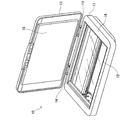
FIG. 1 is an explanatory diagram schematically showing the appearance of a
本実施例のスキャナ10は、いわゆるフラットベッド型のスキャナである。スキャナ10は、後述する内部機構を収納する筐体としてのケース11と、原稿載置板12と、ケース11にヒンジ14を介して回動可能に取り付けられた原稿押さえ13と、を備える。ケース11は、その上面に原稿載置板12を支持する支持部16を有している。
The
原稿載置板12は、略矩形形状の平板であり、支持部16に取り付けられている。原稿載置板12は、例えば、透明なガラス板やプラスチック板により形成されている。また、原稿押さえ13の原稿載置板12に対向する側の面には、例えば略白色に着色された樹脂製のシートにより形成された押さえ面15が配置されている。スキャナ10において、原稿載置板12上に原稿を載せ、原稿押さえ13によって原稿を上から押しつけることにより、原稿を原稿載置板12に密着させることが可能となっている。
The
図2は、スキャナ10の内部機構を概略的に示す平面図である。図2では、図1に示した原稿押さえ13、原稿載置板12、ケース11の支持部16等の図示を省略している。スキャナ10は、ケース11の内部に、キャリッジ300と、ガイドレール210と、タイミングベルト222と、ステッピングモータ226と、度当たり板40と、フラットケーブル240と、制御部230と、電源ユニット250と、をさらに備える。
FIG. 2 is a plan view schematically showing the internal mechanism of the
ガイドレール210は、ケース11の長手方向(図2のX方向)に略平行に配置され、両端においてブラケット212によりケース11に固定されている。キャリッジ300は、ガイドレール210に沿って往復移動可能なようにガイドレール210に支持されている。
The
なお、本明細書では、キャリッジ300がガイドレール210に沿って移動する方向(図2のX方向)を「副走査方向」と呼び、副走査方向に沿った一方の方向(図2のX1方向)を「副走査順方向」と、副走査方向に沿った他方の方向(図2のX2方向)を「副走査逆方向」と呼ぶ。また、副走査方向に直交する方向(図2のY方向)を「主走査方向」と呼び、主走査方向に沿った一方の方向(図2のY1方向)を「主走査順方向」と、主走査方向に沿った他方の方向(図2のY2方向)を「主走査逆方向」と呼ぶ。なお、本実施例における主走査方向は本発明における第1の方向に相当し、副走査方向は本発明における第2の方向に相当する。
In this specification, the direction in which the
タイミングベルト222は、一対のプーリ224の間に張り渡され、その一部がキャリッジ300に結合されている。一対のプーリ224の一方は、ギア228を介してステッピングモータ226により回転駆動される。プーリ224が回転駆動されることにより、タイミングベルト222がプーリ224の間を走行し、タイミングベルト222に結合されたキャリッジ300がガイドレール210に沿って副走査方向に移動する。
The
キャリッジ300は、その上面に、発光部310と受光部320とを有している。発光部310および受光部320は、キャリッジ300の主走査方向に沿った長さのほぼ全域にわたって配置されている。発光部310は、例えばLEDといった発光素子を有し、光を照射する。一方、受光部320は、主走査方向に沿って並んだ複数の受光素子322を有している。受光素子322は、例えばCCDやCMOS撮像素子といったイメージセンサと光をイメージセンサ上に集めるロッドレンズ(セルフォックスレンズ)との組み合わせにより構成され、発光部310から照射された光の反射光を受光し、受光した光の強度に応じた大きさの電圧を出力する。受光部320は、また、受光素子322から出力される電圧値(アナログ値)をデジタル値に変換するA/D変換回路を有する。なお、本実施例のスキャナ10に用いられるキャリッジ300は、一般に密着型と呼ばれるものである。
The
キャリッジ300は、発光部310から照射された光の反射光を受光部320における複数の受光素子322によって検出することにより、受光部320に対向する対象物を主走査方向に沿った幅W1の範囲にわたって光学的に読み取ることができる。キャリッジ300がこのような読み取りを副走査方向に移動しつつ行うことにより、受光部320に対向する対象物の読み取り画像データが生成される。なお、受光部320において、幅W1の範囲外に位置する両端の受光素子322は、予備の受光素子322である。また、スキャナ10におけるキャリッジ300やキャリッジ300を往復移動させる機構(ガイドレール210やタイミングベルト222、ステッピングモータ226など)は、本発明における「読み取り部」に相当する。
The
電源ユニット250は、スキャナ10の動作のための電源を供給する。電源ユニット250は、自ら電力を蓄える構成を有するとしてもよいし、コネクタ252を介して外部から電力の供給を受ける構成を有するとしてもよい。
The
制御部230は、コネクタ234およびフラットケーブル240を介してキャリッジ300と電気的に接続されると共に、ステッピングモータ226とも電気的に接続されており、スキャナ10全体の動作を制御する。例えば、制御部230は、ステッピングモータ226のステップ数を検出して、検出したステップ数に基づいて電源ユニット250からステッピングモータ226への供給電力を制御することにより、キャリッジ300の副走査方向に沿った移動を制御する。また、制御部230は、記憶素子(不図示)を有し、キャリッジ300における読み取りにより生成された画像データ等を記憶することができる。また、制御部230は、図示しないコネクタを介してスキャナ10の外部と接続可能となっており、キャリッジ300における読み取りにより生成された画像データを外部の情報処理装置(図示せず)に伝送することができる。
The
制御部230は、さらに、後述するホームポジション探索処理を実行するための機能的な構成を有している。図3は、制御部230におけるホームポジション探索処理を実行するための機能的な構成を示すブロック図である。図3に示すように、制御部230は、予備読み取り処理部262と、パラメータ設定部264と、第1の画像取得部266と、パターン探索部270と、調整部278と、汎用値設定部282と、第2の画像取得部284と、を含んでいる。また、パターン探索部270は、画素列選択部272と、特徴部分探索部274と、画素グループ設定部276と、を含んでいる。制御部230は、図示しないCPUや記憶領域を有し、CPUによって記憶領域に格納されたコンピュータプログラムが読み出されて実行されることにより、上述した各部の機能を実現する。制御部230に含まれるこれら各部の機能については、後述のホームポジション探索処理の説明において詳述する。
The
また、制御部230は、汎用値設定部282により利用される汎用値テーブルATと、調整部278により利用される調整値テーブルVTと、を有している。汎用値テーブルATと調整値テーブルVTとは、制御部230の有する図示しない記憶領域に格納されている。汎用値テーブルATおよび調整値テーブルVTの内容についても、後述のホームポジション探索処理の説明において詳述する。
In addition, the
図4は、スキャナ10の内部機構を概略的に示す断面図である。図4では、図2に示したスキャナ10の内部構成の内、ガイドレール210、タイミングベルト222、ステッピングモータ226、制御部230、フラットケーブル240、電源ユニット250等の図示を省略している。キャリッジ300は、副走査順方向(図4のX1方向)に、図4の右側にキャリッジ300を破線で示した位置(以下「順方向側限界位置」と呼ぶ)まで移動可能であり、副走査逆方向(図4のX2方向)に、図4の左側にキャリッジ300を破線で示した位置(以下「逆方向側限界位置」と呼ぶ)まで移動可能である。すなわち、キャリッジ300は、キャリッジ300に設けられた受光部320が図2および図4に示した長さL1の範囲内に位置する限度において、副走査方向に沿って往復移動可能である。そのため、キャリッジ300は、図2に示すように、主走査方向に沿った幅W1の範囲と副走査方向に沿った長さL1の範囲とで規定される読み取り可能領域400において、対象物を光学的に読み取ることができる。なお、図4に示すように、キャリッジ300は、逆方向側限界位置において、ケース11に固定された主走査方向に沿った板状の度当たり板40と当接した状態となる。
FIG. 4 is a cross-sectional view schematically showing the internal mechanism of the
また、図4に示すように、キャリッジ300が原稿載置板12上に載置された読み取り対象物としての原稿を読み取ることができる副走査方向の範囲は、長さL2の範囲である。この長さL2の範囲は、長さL1の範囲に包含された範囲である。キャリッジ300は、図2に示すように、主走査方向に沿った幅W1の範囲と副走査方向に沿った長さL2の範囲とで規定される原稿読み取り領域500において、原稿載置板12上に載置された原稿を光学的に読み取ることができる。
As shown in FIG. 4, the range in the sub-scanning direction in which the
支持部16の内側表面には、図4に示すように、基準位置特定プレート100と白基準板30とが設置されている。図5は、ケース11の内部から見たスキャナ10の平面の一部を拡大して示す説明図である。図5には、図4において矢印Mで示す方向から見たスキャナ10の平面の一部を示している。また、図6は、基準位置特定プレート100の平面構成および断面構成を詳細に示す説明図である。図6には、図4において矢印Mで示す方向から基準位置特定プレート100を見た平面と、当該平面を示す図におけるs−s断面とを示している。
As shown in FIG. 4, a reference
基準位置特定プレート100は、反射率の高い色(例えば白色)の略矩形の平板であり、例えばポリプロピレンやポリスチレンにより形成されている。基準位置特定プレート100は、図5に示すように、読み取り可能領域400内であって、原稿読み取り領域500よりも副走査逆方向(X2方向)側に配置されている。
The reference
基準位置特定プレート100は、図6に示すように、一対の略円形形状の位置決め穴110と、一対の矩形形状の第1基準マーク穴120と、1つの矩形形状の第2基準マーク穴140と、を有している。位置決め穴110と第1基準マーク穴120と第2基準マーク穴140とは、すべて、基準位置特定プレート100を基準位置特定プレート100の平面と直交する方向に貫通する穴である。一対の位置決め穴110のそれぞれは、基準位置特定プレート100の主走査方向に沿った両端部付近に配置され、第2基準マーク穴140は、基準位置特定プレート100の平面中心付近に配置されている。また、一対の第1基準マーク穴120は、主走査方向に沿って第2基準マーク穴140を両側から挟むような位置に配置されている。
As shown in FIG. 6, the reference
位置決め穴110と第1基準マーク穴120と第2基準マーク穴140とは、例えば金型を用いたプレス加工や機械加工により形成されており、互いの位置関係が正確となっている。すなわち、基準位置特定プレート100において、位置決め穴110の位置に対する第1基準マーク穴120および第2基準マーク穴140の位置は、正確に決められている。
The
基準位置特定プレート100は、位置決め穴110の位置で、支持部16の内側表面の所定の位置に皿ネジ18によって取り付けられている(図4参照)。なお、基準位置特定プレート100の支持部16への取り付け方法は、皿ネジ18を用いた方法に限られず、例えば、支持部16の表面に設けられた突起が位置決め穴110に挿入された状態で基準位置特定プレート100を接着により支持部16に取り付けるとしてもよい。
The reference
矩形形状の第1基準マーク穴120は、図6に示すように、基準位置特定プレート100が支持部16に取り付けられたときに、2つの第1縁122(122aおよび122b)が主走査方向と略平行となり、第1縁122と直交する2つの第2縁124(124aおよび124b)が副走査方向と略平行となるように、配置されている。また、2つの第1基準マーク穴120の副走査方向に沿った位置は略同一位置となっている。すなわち、2つの第1基準マーク穴120のそれぞれの副走査逆方向(X2方向)側の第1縁122aは、共に所定の直線BL(以下「基準ラインBL」と呼ぶ)上に位置する。
As shown in FIG. 6, the rectangular first
同様に、矩形形状の第2基準マーク穴140は、図6に示すように、基準位置特定プレート100が支持部16に取り付けられたときに、2つの第1縁142(142aおよび142b)が主走査方向と略平行となり、第1縁142と直交する2つの第2縁144(144aおよび144b)が副走査方向と略平行となるように、配置されている。第2基準マーク穴140の副走査逆方向(X2方向)側の第1縁142aは、基準ラインBLよりも副走査逆方向(X2方向)側に位置しており、副走査順方向(X1方向)側の第1縁142bは、基準ラインBLよりも副走査順方向(X1方向)側に位置している。そのため、主走査逆方向(Y2方向)側の第2縁144bは、基準ラインBLと交差する。第2縁144bと基準ラインBLとの交点を「基準点BP」と呼ぶ。
Similarly, the rectangular second
支持部16の内側の表面における基準位置特定プレート100が取り付けられる位置には、図5に示すように、着色領域20が設定されている。支持部16の内側表面は、着色領域20において、反射率の低い色(例えば黒色)で着色されている。着色領域20は、基準位置特定プレート100が取り付けられたときに第1基準マーク穴120および第2基準マーク穴140に対向する領域を含んでいる。そのため、基準位置特定プレート100が支持部16に取り付けられると、第1基準マーク穴120および第2基準マーク穴140を介して着色領域20が表面に露出することとなる。
As shown in FIG. 5, a
支持部16の内側表面には、基準位置特定プレート100と着色領域20とにより、反射率の高い色(例えば白色)の領域と反射率の低い色(例えば黒色)の領域とが主走査方向に沿って交互に並んだパターン(以下「基準パターン」と呼ぶ)が形成される。基準パターンは、主走査方向に沿って隣接する領域間で色のコントラストが大きいパターンとなる。支持部16の内側表面における基準パターンが形成された領域は、本発明におけるパターン領域に相当する。なお、着色領域20の代わりに、黒色で着色されたシートを用いて基準パターンを形成するとしてもよい。
Due to the reference
基準パターンにおける基準ラインBLおよび基準点BPは、原稿読み取り領域500の位置を特定するための基準位置として用いられる。より詳細には、図5に示すように、基準ラインBLから副走査順方向(X1方向)に距離L3だけ離れ、基準点BPから主走査順方向(Y1方向)に距離W3だけ離れた点が、原稿読み取り領域500の読み取り領域参照点510として特定される。読み取り領域参照点510は、矩形形状の原稿読み取り領域500の主走査順方向(Y1方向)側および副走査逆方向(X2方向)側の頂点である。読み取り領域参照点510の位置が特定されれば、原稿読み取り領域500の主走査方向および副走査方向に沿った大きさ(W1およびL2、図2参照)に基づき、原稿読み取り領域500の位置が特定される。すなわち、基準パターンは、原稿読み取り領域500の位置を特定するための基準位置(基準ラインBLおよび基準点BPの位置)を規定するパターンであると言える。
The reference line BL and the reference point BP in the reference pattern are used as a reference position for specifying the position of the
また、本実施例のスキャナ10では、基準パターンによってキャリッジ300のホームポジションも規定される。ここで、キャリッジ300のホームポジションは、キャリッジ300による原稿の読み取りが行われていないときのキャリッジ300の待機位置である。本実施例では、キャリッジ300のホームポジションは、キャリッジ300の受光部320が白基準板30に対向することとなるような位置に設定されている。図5には、キャリッジ300のホームポジションにおける受光部320の位置を符号HPを付した一点鎖線で示している。キャリッジ300のホームポジションにおける受光部320の位置は、基準パターンにおける基準ラインBLから副走査逆方向(X2方向)に距離L4だけ離れた位置として設定される。
In the
白基準板30は、白色の略矩形形状の平板であり、例えばポリプロピレンやポリスチレンにより形成されている。白基準板30は、図4および図5に示すように、基準位置特定プレート100よりも副走査逆方向(X2方向)側の位置に配置されている。白基準板30の位置は、基準位置特定プレート100の基準パターンの位置やキャリッジ300のホームポジションとの関係に基づき設定されている。白基準板30の副走査方向に沿った大きさは、読み取り可能領域400内に含まれるような大きさに設定され、主走査方向に沿った大きさは、読み取り可能領域400の主走査方向に沿った幅W1(図2参照)よりも大きい値に設定されている。白基準板30は、例えば接着によって支持部16の内側表面に固定されている。なお、白基準板30の色である白色は、本発明における基準色に相当し、支持部16の内側表面において白基準板30が設置された領域は、本発明における基準色領域に相当する。
The
図7は、本実施例のスキャナ10によるホームポジション探索処理の流れを示すフローチャートである。図8は、ホームポジション探索処理における基準パターン探索処理の流れを示すフローチャートである。図9は、ホームポジション探索処理における特徴点探索処理の流れを示すフローチャートである。また、図10ないし図13は、ホームポジション探索処理におけるキャリッジ300の動きの一例を示す説明図である。
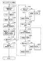
FIG. 7 is a flowchart showing the flow of home position search processing by the
スキャナ10によるホームポジション探索処理は、基準パターンにおける基準位置(基準ラインBLおよび基準点BPの位置)に基づきキャリッジ300のホームポジションを探索し、キャリッジ300をホームポジションに移動させる処理である。ホームポジション探索処理は、例えばスキャナ10の電源ON直後の初期化処理の一部として実行される。なお、本実施例のスキャナ10では、正常に電源OFFの操作が行われた際にはキャリッジ300がホームポジション付近に移動された後に電源が切れるように設定されているため、正常な電源OFF処理の後の電源ON直後のホームポジション探索処理の開始時には、キャリッジ300はホームポジション付近に位置していると想定される。
The home position search process by the
ステップS110(図7)では、制御部230の予備読み取り処理部262(図3)が、キャリッジ300やステッピングモータ226(図2)を制御して予備読み取りPRを行う。予備読み取りPRは、スキャナ10による読み取りの際に用いられる所定の読み取りパラメータの値を設定するために、所定の読み取り範囲を予備的に読み取る処理である。予備読み取りPRは、読み取りパラメータの値が正常に設定されるように、白基準板30(図5)の下で行われるべき処理である。予備読み取りPRでは、キャリッジ300を副走査順方向(X1方向)に移動させつつ、読み取りが行われる。なお、上述した所定の読み取りパラメータは、読み取り時における受光素子322からの出力信号に対し、光量不均一・周辺減光・受光素子322の感度ムラなどの影響を考慮した補正に用いるパラメータであり、発光部310の点灯時間と、アナログフロントエンドのオフセット値と、シェーディングデータとの少なくとも1つを含む。
In step S110 (FIG. 7), the preliminary reading processing unit 262 (FIG. 3) of the
ホームポジション探索処理におけるキャリッジ300の動きを示した図10ないし図13の内、図10は、ホームポジション探索処理の開始時のキャリッジ300の位置(以下「開始時キャリッジ位置SP」と呼ぶ)が正常な位置であるホームポジション付近であった場合のキャリッジ300の動きを示している。なお、図10ないし図13において、LPはキャリッジ300が逆方向側限界位置(図4参照)にあるときの受光部320の位置を示しており、HPはキャリッジ300がホームポジションにあるときの受光部320の位置を示しており、PPは基準パターンの副走査方向に沿った位置を示しており、WPは白基準板30の副走査方向に沿った位置を示している。図10に示すように、開始時キャリッジ位置SPがホームポジション付近であった場合には、予備読み取りPRによって白基準板30が読み取られることとなる。
10 to 13 showing the movement of the
一方、例えば異常終了による電源OFF後のように、開始時キャリッジ位置SPがホームポジションから副走査逆方向(X2方向)側に大きくずれていたり(図11参照)、副走査順方向(X1方向)側に大きくずれていたり(図12および図13参照)する場合がある。開始時キャリッジ位置SPがホームポジションから大きくずれていた場合には、予備読み取りPRによって白基準板30が位置する範囲以外の範囲が読み取られる可能性がある。
On the other hand, for example, after the power is turned off due to abnormal termination, the starting carriage position SP is greatly shifted from the home position in the sub-scanning reverse direction (X2 direction) (see FIG. 11), or in the sub-scanning forward direction (X1 direction). There is a case where it is greatly shifted to the side (see FIGS. 12 and 13). When the starting carriage position SP is greatly deviated from the home position, there is a possibility that a range other than the range where the
ステップS120(図7)では、制御部230のパラメータ設定部264(図3)が、予備読み取りPRにおける読み取り結果に基づき、読み取りパラメータの値を設定する。読み取りパラメータの値は、予備読み取りPRにおける読み取り結果と白基準板30の色、すなわち基準色としての白色との関係に基づき設定される。より詳細には、パラメータ設定部264は、上記読み取りパラメータについて、予備読み取りPRにおける各受光素子322からの出力信号が白色を表す信号に補正されるような値を算出する。なお、読み取りパラメータ値がこのように設定されることから、開始時キャリッジ位置SPがホームポジションから大きくずれていた場合(図11ないし図13参照)には、設定される読み取りパラメータの値が適切な値とはならない可能性がある。
In step S120 (FIG. 7), the parameter setting unit 264 (FIG. 3) of the
ステップS130(図7)では、制御部230(図3)が、キャリッジ300を所定移動量分だけ副走査順方向(X1方向)に移動させる。ステップS130におけるキャリッジ300の移動を「移動A」と表すものとする。移動Aにおける副走査順方向に沿った移動量は、開始時キャリッジ位置SPがホームポジション付近であった場合に(図10参照)キャリッジ300が予備読み取りPR完了時の位置から基準パターンの直前の位置まで移動することとなる量に設定されている。
In step S130 (FIG. 7), the control unit 230 (FIG. 3) moves the
ステップS140(図7)では、制御部230の第1の画像取得部266(図3)が、キャリッジ300に、副走査順方向(X1方向)への移動をさせつつ読み取りを行わせ、読み取り画像I1を表す読み取り画像データを生成する。ステップS140における読み取りを「読み取りR1」と表すものとする。読み取りR1により生成される画像データは、本発明における第1の画像データに相当する。
In step S140 (FIG. 7), the first image acquisition unit 266 (FIG. 3) of the
読み取りR1における副走査順方向(X1方向)への移動量は、開始時キャリッジ位置SPがホームポジション付近であって予備読み取りPRにより白基準板30が読み取られた場合に、読み取りR1によって基準パターンが読み取られることとなるような移動量に設定されている。そのため、開始時キャリッジ位置SPがホームポジション付近であった場合には(図10参照)、読み取りR1により生成される読み取り画像I1は、基準パターンの画像を含む画像となる。一方、開始時キャリッジ位置SPがホームポジションから大きくずれていた場合(図11ないし図13参照)には、読み取り画像I1が基準パターンの画像を含まない画像となる可能性がある。
The amount of movement in the sub-scanning forward direction (X1 direction) in reading R1 is that the reference pattern is determined by reading R1 when the start carriage position SP is near the home position and the
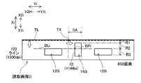
図14は、読み取りR1により生成される読み取り画像I1の一例を示す説明図である。図14に示した読み取り画像I1の例では、読み取り画像I1に基準パターンの画像が含まれている。すなわち、読み取り画像I1に基準パターンにおける第1基準マーク穴120(図6)の画像120iと第2基準マーク穴140の画像140iとが含まれている。
FIG. 14 is an explanatory diagram illustrating an example of the read image I1 generated by the reading R1. In the example of the read image I1 illustrated in FIG. 14, the read image I1 includes a reference pattern image. That is, the read image I1 includes the
図14に示すように、読み取り画像I1のサイズは、例えばスキャナ10の主走査方向に対応する方向(図14のYi方向)に850画素、副走査方向に対応する方向(図14のXi方向)に122画素というサイズである。本実施例では、主走査方向に対応する方向(Yi方向)に沿って並ぶ850個の画素により構成されるラインを画素ライン(または画素列)と呼ぶ。読み取り画像I1は、122本の画素ラインにより構成された画像といえる。なお、本実施例では、読み取り画像I1の主走査方向に対応する方向(Yi方向)に沿った解像度は1200dpiである。また、読み取り画像I1の副走査方向に対応する方向(Xi方向)に沿った解像度は1200dpiであり、後述の読み取りR2により生成される読み取り画像I2の副走査方向に対応する方向に沿った解像度(300dpi)よりも高解像度となっている。なお、読み取り画像I1の副走査方向に対応する方向(Xi方向)に沿った解像度は、本発明における第1の副走査方向解像度に相当する。 As shown in FIG. 14, the size of the read image I1 is, for example, 850 pixels in the direction corresponding to the main scanning direction of the scanner 10 (Yi direction in FIG. 14), and the direction corresponding to the sub-scanning direction (Xi direction in FIG. 14). The size is 122 pixels. In this embodiment, a line composed of 850 pixels arranged along the direction (Yi direction) corresponding to the main scanning direction is referred to as a pixel line (or pixel column). The read image I1 can be said to be an image composed of 122 pixel lines. In the present embodiment, the resolution along the direction (Yi direction) corresponding to the main scanning direction of the read image I1 is 1200 dpi. Further, the resolution along the direction (Xi direction) corresponding to the sub-scanning direction of the read image I1 is 1200 dpi, and the resolution along the direction corresponding to the sub-scanning direction of the read image I2 generated by reading R2 described later ( The resolution is higher than 300 dpi). Note that the resolution along the direction (Xi direction) corresponding to the sub-scanning direction of the read image I1 corresponds to the first sub-scanning direction resolution in the present invention.
なお、読み取り画像I1および後述の読み取り画像I2において、スキャナ10の主走査方向に対応する方向(図14のYi方向)を「主走査対応方向」と呼び、主走査順方向に対応する方向(図14のY1i方向)を「主走査順対応方向」と、主走査逆方向に対応する方向(図14のY2i方向)を「主走査逆対応方向」と呼ぶ。また、スキャナ10の副走査方向に対応する方向(図14のXi方向)を「副走査対応方向」と呼び、副走査順方向に対応する方向(図14のX1i方向)を「副走査順対応方向」と、副走査逆方向に対応する方向(図14のX2i方向)を「副走査逆対応方向」と呼ぶ。 In the read image I1 and a read image I2, which will be described later, the direction corresponding to the main scanning direction of the scanner 10 (the Yi direction in FIG. 14) is referred to as the “main scanning corresponding direction”, and the direction corresponding to the main scanning forward direction (see FIG. 14 (Y1i direction) is referred to as “main scanning order corresponding direction”, and the direction corresponding to the main scanning reverse direction (Y2i direction in FIG. 14) is referred to as “main scanning reverse corresponding direction”. Further, the direction corresponding to the sub-scanning direction of the scanner 10 (Xi direction in FIG. 14) is called “sub-scanning corresponding direction”, and the direction corresponding to the sub-scanning forward direction (X1i direction in FIG. 14) is “corresponding to the sub-scanning order”. The direction (direction X2i in FIG. 14) corresponding to the “direction” and the reverse sub-scanning direction is referred to as the “sub-scanning reverse corresponding direction”.
ステップS150(図7)では、制御部230のパターン探索部270(図3)が、読み取り画像I1から基準パターンの画像を探索する。より詳細には、パターン探索部270は、読み取り画像I1から基準パターンの基準ラインBL(図6)の画像BLiと基準点BPの画像BPiとを探索する。
In step S150 (FIG. 7), the pattern search unit 270 (FIG. 3) of the
基準パターンの画像の探索処理の流れを示す図8において、ステップS310では、パターン探索部270の画素列選択部272(図3)が、対象ラインTLを設定する。画素列選択部272は、読み取り画像I1(図14)において最も副走査逆対応方向(X2i方向)に位置する画素ラインを対象ラインTLとして選択する。
In FIG. 8 showing the flow of the search process of the reference pattern image, in step S310, the pixel column selection unit 272 (FIG. 3) of the
ステップS330(図8)では、パターン探索部270の特徴部分探索部274(図3)が、対象ラインTLにおいて特徴点CPを探索する。ここで、特徴点CPは、基準パターンの特徴部分を表す画像である特徴画像CIを構成する点である。本実施例では、基準パターンにおける第2基準マーク穴140(図6)の主走査逆方向(Y2方向)側の第2縁144bが特徴部分として用いられる。そのため、特徴画像CIは、図14に示すように、第2基準マーク穴140の主走査逆方向側の第2縁144bを表す画像144biとなる。なお、基準パターンにおける特徴部分は、反射率の高い色の部分(基準位置特定プレート100)と反射率の低い色の部分(第2基準マーク穴140を介して露出された着色領域20)との境界部分となるため、特徴画像CIは輝度値の大きい画像と輝度値の小さい画像との境界の画像となる。
In step S330 (FIG. 8), the feature portion search unit 274 (FIG. 3) of the
特徴点CPの探索処理の流れを示す図9において、ステップS510では、特徴部分探索部274(図3)が、対象ラインTL上の一部の範囲を特徴点CPの探索を行う探索範囲として設定する。本実施例では、ある対象ラインTLを対象とした初めての特徴点CPの探索の際には、図14に示す初期探索範囲SAを探索範囲として設定する。初期探索範囲SAは、読み取り画像I1が基準パターンの画像を含む画像である場合に特徴画像CIが位置すべき位置を含む範囲となるように、基準パターンとキャリッジ300との関係を考慮して予め設定される。一方、後述するように、ある対象ラインTLを対象とした2回目以降の特徴点CPの探索の際には、初期探索範囲SAの内の未探索の範囲が探索範囲として設定される。
In FIG. 9 showing the flow of the feature point CP search process, in step S510, the feature portion search unit 274 (FIG. 3) sets a partial range on the target line TL as a search range for searching for the feature point CP. To do. In the present embodiment, when searching for a feature point CP for the first time targeting a certain target line TL, an initial search range SA shown in FIG. 14 is set as the search range. The initial search range SA is determined in advance in consideration of the relationship between the reference pattern and the
ステップS520(図9)では、特徴部分探索部274(図3)が、ステップS510で設定された対象ラインTL上の探索範囲において、対象画素TXを設定する。具体的には、特徴部分探索部274は、対象ラインTL上の探索範囲における最も主走査逆対応方向(図14のY2i方向)側の画素を対象画素TXとして設定する。
In step S520 (FIG. 9), the feature portion search unit 274 (FIG. 3) sets the target pixel TX in the search range on the target line TL set in step S510. Specifically, the feature
ステップS530(図9)では、特徴部分探索部274が、対象画素TXについて、所定の条件を満たすか否かの判定を行う。ここで所定の条件は、対象画素TXの輝度値が第1の閾値T1以下であり、かつ主走査逆対応方向(Y2i方向)に沿って対象画素TXに隣接する画素の輝度値が第1の閾値T1より大きいことである。上記所定の条件が満たされると判定された場合には(ステップS530:Yes)、対象画素TXが特徴点CPとして検出される(ステップS560)。
In step S530 (FIG. 9), the feature
図15は、所定の条件を用いた特徴点CPの検出方法を示す説明図である。図15に示すように、対象ラインTL上の初期探索範囲SAにおいて、輝度値が大きい値から小さい値に急激に変化する位置が特徴画像CIに対応した点である特徴点CPであると考えられる。従って、第1の閾値T1を反射率の低い色に対応した低い値(例えば輝度値の最大値が255である場合における100)に設定すると、上記所定の条件が満たされた点が特徴点CPであると考えられる。 FIG. 15 is an explanatory diagram showing a method for detecting a feature point CP using a predetermined condition. As shown in FIG. 15, in the initial search range SA on the target line TL, it is considered that the position where the luminance value suddenly changes from a large value to a small value is a feature point CP that is a point corresponding to the feature image CI. . Therefore, when the first threshold value T1 is set to a low value corresponding to a color with low reflectance (for example, 100 when the maximum luminance value is 255), a point where the predetermined condition is satisfied is a feature point CP. It is thought that.
上記所定の条件が満たされないと判定された場合には(ステップS530:No)、特徴部分探索部274は、設定された探索範囲内のすべての画素についてステップS530の判定が完了したかを判定する(ステップS540)。未だステップS530の判定の対象となっていない画素が存在する場合には(ステップS540:No)、特徴部分探索部274は、現時点で対象画素TXとして設定されている画素の主走査順対応方向(Y1i方向)側の隣接画素を、新たな対象画素TXとして変更設定し(ステップS550)、再度ステップS530における判定を行う。このように、主走査順対応方向(Y1i方向)に沿って順に、対象ラインTL上の画素が対象画素TXとして選択され、ステップS530の判定が行われる。
When it is determined that the predetermined condition is not satisfied (step S530: No), the feature
ステップS540において、探索範囲内のすべての画素についてステップS530の判定が完了したと判定された場合には(ステップS540:Yes)、特徴部分探索部274は、対象ラインTLにおける特徴点CPの検出は失敗したと判断する(ステップS570)。
If it is determined in step S540 that the determination in step S530 has been completed for all pixels within the search range (step S540: Yes), the feature
図8に戻り、ステップS330において特徴点CPが検出されなかった場合には(ステップS340:No)、制御部230のパターン探索部270(図3)が、読み取り画像I1のすべての画素ラインが特徴点CPの探索対象である対象ラインTLとして選択されたか否かを判定する(ステップS430)。未だ対象ラインTLとして選択されていない画素ラインが存在する場合には(ステップS430:No)、画素列選択部272(図3)は、現時点で対象ラインTLとして設定されている画素ラインの副走査順対応方向(X1i方向)側の隣接画素ラインを、新たな対象ラインTLとして変更設定する(ステップS440)。対象ラインTLが変更設定されると、新たな対象ラインTLについて、再度ステップS330における特徴点CPの検出処理が行われる。このように、副走査順対応方向(X1i方向)に沿って順に、読み取り画像I1を構成する画素ラインが対象ラインTLとして選択され、特徴点CPの検出処理が行われる。
Returning to FIG. 8, when the feature point CP is not detected in step S330 (step S340: No), the pattern search unit 270 (FIG. 3) of the
ステップS430において、読み取り画像I1を構成するすべての画素ラインについてステップS330における特徴点CPの探索が完了したと判定された場合には(ステップS430:Yes)、パターン探索部270(図3)は、読み取り画像I1からの基準パターンの画像の検出は失敗に終わったと判断する(ステップS450)。 If it is determined in step S430 that the search for the feature point CP in step S330 has been completed for all the pixel lines constituting the read image I1 (step S430: Yes), the pattern search unit 270 (FIG. 3) It is determined that the detection of the reference pattern image from the read image I1 has failed (step S450).
ステップS330の特徴点CPの探索処理では、読み取り画像I1に基準パターンの画像が含まれている場合には、図14に示す読み取り画像I1の範囲R1において、対象ラインTLから特徴点CPは検出されないものと考えられる。一方、図14に示す範囲R2およびR3においては、対象ラインTLから特徴点CPが検出されるものと考えられる。一方、読み取り画像I1に基準パターンの画像が含まれていない場合には、特徴点CPは検出されないものと考えられる。ただし、いずれの場合であっても、本実施例では図9のステップS530に示した比較的単純な条件を用いた判定により特徴点CPの検出を行っているため、ごみやノイズ等の影響により、特徴画像CIに対応した点ではない点が特徴点CPとして誤検出される可能性はある。 In the process of searching for the feature point CP in step S330, if the reference image is included in the read image I1, the feature point CP is not detected from the target line TL in the range R1 of the read image I1 shown in FIG. It is considered a thing. On the other hand, in the ranges R2 and R3 shown in FIG. 14, it is considered that the feature point CP is detected from the target line TL. On the other hand, when the image of the reference pattern is not included in the read image I1, it is considered that the feature point CP is not detected. However, in any case, since the feature point CP is detected by the determination using the relatively simple condition shown in step S530 of FIG. 9 in this embodiment, the feature point CP is affected by dust and noise. There is a possibility that a point that is not a point corresponding to the feature image CI is erroneously detected as the feature point CP.
ステップS330(図8)において特徴点CPが検出された場合には(ステップS340:Yes)、制御部230の調整部278(図3)が、調整値Vaを設定する(ステップS350)。ここで、調整値Vaは、検出された特徴点CPの位置を主走査対応方向(Yi方向)に沿って調整するための値である。
When the feature point CP is detected in step S330 (FIG. 8) (step S340: Yes), the adjustment unit 278 (FIG. 3) of the
調整値Vaの設定は、調整値テーブルVT(図3)を用いて行われる。図16は、調整値テーブルVTの内容の一例を示す説明図である。図16に示すように、本実施例では、調整値Vaの既設定回数に応じた調整値Vaが、画素を単位として定められている。例えば、既設定回数が0回、すなわち初めての調整値Vaの設定時においては、調整値Vaは0画素に設定され、特徴点CPの位置の主走査対応方向に沿った調整は行われない。また、既設定回数が1回の場合には、調整値Vaは+1画素、すなわち特徴点CPの位置が主走査順対応方向(Y1i方向)に1画素分移動されるような値に設定される。また、既設定回数が2回の場合には、調整値Vaは−1画素、すなわち特徴点CPの位置が主走査逆対応方向(Y2i方向)に1画素分移動されるような値に設定される。なお、調整値テーブルVTには、既設定回数が10回までの調整値Vaが規定されている。 The adjustment value Va is set using the adjustment value table VT (FIG. 3). FIG. 16 is an explanatory diagram showing an example of the contents of the adjustment value table VT. As shown in FIG. 16, in this embodiment, the adjustment value Va corresponding to the preset number of adjustment values Va is determined in units of pixels. For example, when the preset number is 0, that is, when the adjustment value Va is set for the first time, the adjustment value Va is set to 0 pixel, and the adjustment of the position of the feature point CP along the main scanning corresponding direction is not performed. Further, when the preset number of times is 1, the adjustment value Va is set to a value such that the position of the feature point CP is moved by one pixel in the main scanning order corresponding direction (Y1i direction). . When the preset number of times is 2, the adjustment value Va is set to a value such that the position of the feature point CP is moved by one pixel in the main scanning reverse corresponding direction (Y2i direction). The The adjustment value table VT defines an adjustment value Va up to 10 preset times.
ステップS360(図8)では、調整部278(図3)が、調整特徴点CPaを設定する。調整特徴点CPaは、ステップS350で設定された調整値Vaに基づき特徴点CPの位置を主走査対応方向に沿って調整した後の点である。 In step S360 (FIG. 8), the adjustment unit 278 (FIG. 3) sets the adjustment feature point CPa. The adjustment feature point CPa is a point after adjusting the position of the feature point CP along the main scanning corresponding direction based on the adjustment value Va set in step S350.
ステップS370(図8)では、画素グループ設定部276(図3)が、調整特徴点CPaに基づき、対象ラインTL上に画素グループPGを設定する。図17は、画素グループPGの設定方法を示す説明図である。図17に示すように、本実施例では、基準パターン(図6)を構成する7つの領域に対応した7つの画素グループPG(PG1〜PG7)が設定される。ここで、基準パターンを構成する7つの領域とは、3つの反射率の低い色の領域(2つの第1基準マーク穴120および1つの第2基準マーク穴140の部分)と、当該3つの領域に隣接した4つの反射率の高い色の領域(基準位置特定プレート100の部分)と、を意味している。 In step S370 (FIG. 8), the pixel group setting unit 276 (FIG. 3) sets a pixel group PG on the target line TL based on the adjustment feature point CPa. FIG. 17 is an explanatory diagram illustrating a method for setting the pixel group PG. As shown in FIG. 17, in this embodiment, seven pixel groups PG (PG1 to PG7) corresponding to the seven regions constituting the reference pattern (FIG. 6) are set. Here, the seven areas constituting the reference pattern are three low-reflectance color areas (two first reference mark holes 120 and one second reference mark hole 140), and the three areas. And four high-reflectance color regions (parts of the reference position specifying plate 100) adjacent to the.
本実施例では、各画素グループPGの主走査対応方向(Yi方向)に沿った位置が、調整特徴点CPaの位置を基準として予め設定されている。例えば、画素グループPG2の主走査逆対応方向(Y2i方向)側の端の位置は、調整特徴点CPaの位置に設定され、主走査順対応方向(Y1i方向)側の端の位置は、調整特徴点CPaから23画素分Y1i方向側に離れた位置に設定されている。従って、画素グループPG2は、画素数24個の画素グループとなる。他の画素グループPGの位置も同様に設定されている。各画素グループPGの主走査対応方向(Yi方向)に沿った位置は、読み取り画像I1が基準パターンの画像を含む場合に、7つの画素グループPG(PG1〜PG7)が基準パターンを構成する7つの領域に対応することとなるように、基準パターンとキャリッジ300との関係に基づき予め定められている。なお、図17に示すように、隣接する画素グループPG間(例えばPG1とPG5との間)には、所定画素数分の間隔が設けられている。
In this embodiment, the position of each pixel group PG along the main scanning corresponding direction (Yi direction) is set in advance with reference to the position of the adjustment feature point CPa. For example, the position of the end of the pixel group PG2 on the side opposite to the main scanning direction (Y2i direction) is set to the position of the adjustment feature point CPa, and the position of the end on the side of the main scanning order corresponding direction (Y1i direction) is the adjustment feature. It is set at a position away from the point CPa by 23 pixels in the Y1i direction. Therefore, the pixel group PG2 is a pixel group having 24 pixels. The positions of other pixel groups PG are set similarly. The positions along the main scanning corresponding direction (Yi direction) of each pixel group PG are the seven pixel groups PG (PG1 to PG7) that form the reference pattern when the read image I1 includes the image of the reference pattern. It is determined in advance based on the relationship between the reference pattern and the
ステップS380(図8)では、パターン探索部270(図3)が、設定された画素グループPG毎に条件判定を行う。条件判定は、反射率の低い色の領域に対応した画素グループPG(PG1,2,3)については、画素グループPGに含まれる全画素の内、輝度値が上述の第1の閾値T1以下である画素数の割合が所定の割合(例えば8割)以上か否かという条件を用いて行われる。この条件を満たす画素グループPGは、基準パターンの反射率の低い色の領域の画像を表しているものと考えられる。また、反射率の高い色の領域に対応した画素グループPG(PG4,5,6,7)については、画素グループPGに含まれる全画素の内、輝度値が第2の閾値T2以上である画素数の割合が所定の割合(例えば8割)以上か否かという条件を用いて行われる。ここで、第2の閾値T2は、反射率の高い色に対応した値(例えば輝度の最大値が255である場合における180)に設定される。この条件を満たす画素グループPGは、基準パターンの反射率の高い色の領域の画像を表しているものと考えられる。 In step S380 (FIG. 8), the pattern search unit 270 (FIG. 3) performs condition determination for each set pixel group PG. In the condition determination, for the pixel group PG (PG1, 2, 3) corresponding to the color region with low reflectance, the luminance value is less than or equal to the first threshold value T1 among all the pixels included in the pixel group PG. This is performed using the condition that the ratio of a certain number of pixels is a predetermined ratio (for example, 80%) or more. A pixel group PG that satisfies this condition is considered to represent an image of a color region having a low reflectance of the reference pattern. For the pixel group PG (PG4, 5, 6, 7) corresponding to the color region having a high reflectance, pixels having a luminance value equal to or higher than the second threshold T2 among all the pixels included in the pixel group PG. It is performed using the condition that the ratio of the number is a predetermined ratio (for example, 80%) or more. Here, the second threshold value T2 is set to a value corresponding to a color having a high reflectance (for example, 180 when the maximum luminance value is 255). A pixel group PG satisfying this condition is considered to represent an image of a color region having a high reflectance of the reference pattern.
なお、上記条件が、画素グループPGに含まれる全画素の輝度値が第1の閾値T1以下(または第2の閾値T2以上)であるか否かという条件とされていないのは、ごみやノイズ等の影響を考慮して、条件が厳しくなりすぎることによる基準パターンの検出漏れを抑制するためである。また、上述したように、隣接する画素グループPG間に所定画素数分の間隔が設けられているのも同じ理由からである。 Note that the above condition is not a condition for determining whether or not the luminance values of all the pixels included in the pixel group PG are equal to or lower than the first threshold value T1 (or higher than the second threshold value T2). This is because the detection of the reference pattern due to excessively severe conditions is suppressed in consideration of the influence of the above. In addition, as described above, the interval corresponding to the predetermined number of pixels is provided between the adjacent pixel groups PG for the same reason.
条件判定は、例えば、まず画素グループPG1について実行され、その後PG2,PG3,PG4,PG5,PG6,PG7の順に実行される。7つの画素グループPGのすべてについて条件が満たされると判定された場合には(ステップS390:No)、パターン探索部270(図3)は、基準パターンの画像の検出に成功したものと判断する(ステップS400)。すなわち、パターン探索部270は、現在設定されている対象ラインTLが基準パターンの基準ラインBL(図6)に対応した画像BLiであると決定し、調整特徴点CPaが基準点BPに対応した画像BPiであると決定する。
For example, the condition determination is first executed for the pixel group PG1, and then executed in the order of PG2, PG3, PG4, PG5, PG6, PG7. When it is determined that the condition is satisfied for all of the seven pixel groups PG (step S390: No), the pattern search unit 270 (FIG. 3) determines that the reference pattern image has been successfully detected (see FIG. 3). Step S400). That is, the
一方、1つの画素グループPGについての判定において条件が満たされなかった場合には(ステップS390:Yes)、他の画素グループPGについての判定が実行済みであるか否かに関わらず、ステップS380における条件判定は終了される。この場合には、調整部278(図3)が、調整値テーブルVT(図16)に定義されたすべての値がVaとして設定されたか否かを判定する(ステップS410)。未だ調整値Vaとして設定されていない値がある場合には(ステップS410:No)、調整部278は、調整値Vaを変更設定する(ステップS420)。すなわち、既設定回数の1つ大きい欄の値を新たな調整値Vaとして設定する。
On the other hand, when the condition is not satisfied in the determination for one pixel group PG (step S390: Yes), the determination in step S380 is performed regardless of whether the determination for the other pixel group PG has been executed. Condition determination is terminated. In this case, the adjustment unit 278 (FIG. 3) determines whether all the values defined in the adjustment value table VT (FIG. 16) have been set as Va (step S410). If there is a value that has not yet been set as the adjustment value Va (step S410: No), the
その後、変更設定後の調整値Vaに基づき、再度、調整特徴点CPaの設定(ステップS360)、画素グループPGの設定(ステップS370)、画素グループPG毎の条件判定(ステップS380)が実行される。これにより、7つの画素グループPGの位置を主走査対応方向に微調整しつつ、画素グループPGを用いた基準パターンの画像の探索が実行される。調整値テーブルVTに規定されたすべての値が調整値Vaとして既に設定されていた場合には(ステップS410:Yes)、処理はステップS330の特徴点CPの探索に戻る。 Thereafter, based on the adjustment value Va after the change setting, setting of the adjustment feature point CPa (step S360), setting of the pixel group PG (step S370), and condition determination for each pixel group PG (step S380) are executed again. . Thus, the search for the image of the reference pattern using the pixel group PG is executed while finely adjusting the positions of the seven pixel groups PG in the main scanning corresponding direction. If all values specified in the adjustment value table VT have already been set as the adjustment value Va (step S410: Yes), the process returns to the search for the feature point CP in step S330.
このように、読み取り画像I1における基準パターンの画像の探索処理(図8)では、副走査順対応方向(X1i方向)に沿って順に対象ラインTLが設定され、対象ラインTL上の探索範囲において特徴点CPの探索が行われる。特徴点CPが検出された場合には、対象ラインTLについて画素グループPGの設定および画素グループPG毎の条件判定が行われる。そのため、図17に示すように、対象ラインTLが範囲R1内に設定されているときには、対象ラインTLから特徴点CPが検出されないものと考えられ、画素グループPGの設定や条件判定は実行されない。一方、対象ラインTLが範囲R2内に設定された場合には、対象ラインTLから特徴点CPが検出されるものの、画素グループPG毎の条件判定において条件が満たされないと判定される。対象ラインTLが範囲R3内にはじめて設定されたときに、対象ラインTLから特徴点CPが検出され、さらに、すべての画素グループPG毎の条件判定において条件が満たされると判定されると考えられる。このときの対象ラインTLが、基準ラインBLに対応した画像BLiとされ、調整特徴点CPaが基準点BPに対応した画像BPiとされる。 In this way, in the search process of the image of the reference pattern in the read image I1 (FIG. 8), the target line TL is set in order along the sub-scanning order corresponding direction (X1i direction), and the feature is found in the search range on the target line TL. A search for a point CP is performed. When the feature point CP is detected, the setting of the pixel group PG and the condition determination for each pixel group PG are performed for the target line TL. Therefore, as shown in FIG. 17, when the target line TL is set within the range R1, it is considered that the feature point CP is not detected from the target line TL, and the setting of the pixel group PG and the condition determination are not executed. On the other hand, when the target line TL is set within the range R2, the feature point CP is detected from the target line TL, but it is determined that the condition is not satisfied in the condition determination for each pixel group PG. When the target line TL is set for the first time in the range R3, the feature point CP is detected from the target line TL, and it is considered that the condition is determined to be satisfied in the condition determination for every pixel group PG. The target line TL at this time is an image BLi corresponding to the reference line BL, and the adjustment feature point CPa is an image BPi corresponding to the reference point BP.
なお、特徴点CPの探索(図8のステップS330)において特徴画像CIに対応した点ではない点が特徴点CPとして誤検出された場合には、その後の条件判定(ステップS380)において基準パターンの画像の検出に失敗することとなる。 If a point that does not correspond to the feature image CI is erroneously detected as the feature point CP in the search for the feature point CP (step S330 in FIG. 8), the reference pattern of the reference pattern is determined in the subsequent condition determination (step S380). Image detection will fail.
ホームポジション探索処理(図7)のステップS150で読み取り画像I1から基準パターンの画像が検出された場合には(ステップS160:Yes)、制御部230(図3)は、キャリッジ300をホームポジションに移動させた後(ステップS170)、ホームポジション探索処理を終了する。ステップS170におけるキャリッジ300の移動を「移動B」と表すものとする。
When a reference pattern image is detected from the read image I1 in step S150 of the home position search process (FIG. 7) (step S160: Yes), the control unit 230 (FIG. 3) moves the
図5に示すように、キャリッジ300のホームポジションにおける受光部320の位置(図5のHPの位置)は、基準パターンの基準ラインBLから副走査逆方向(X2方向)側にL4離れた位置であると決められている。また、制御部230は、読み取り画像I1において検出された基準パターンの画像における基準ラインBLに対応した画像BLiの位置を把握している。制御部230は、読み取り画像I1における画像BLiの位置に基づき移動Bにおける移動量を算出し、キャリッジ300を正確にホームポジションに移動させる(図10参照)。
As shown in FIG. 5, the position of the
一方、ステップS150(図7)における読み取り画像I1からの基準パターンの画像の検出に失敗し(ステップS160:No)、かつ、その失敗が初めての失敗である場合には(ステップS180:Yes)、制御部230(図3)は、キャリッジ300を副走査順方向(X1方向)に所定の移動量だけ移動させる(ステップS190)。ステップS190におけるキャリッジ300の移動を「移動C」と表すものとする。
On the other hand, when the detection of the image of the reference pattern from the read image I1 in step S150 (FIG. 7) fails (step S160: No) and the failure is the first failure (step S180: Yes), The controller 230 (FIG. 3) moves the
上述したように、開始時キャリッジ位置SPがホームポジションから大きくずれていた場合(図11ないし図13参照)には、読み取り画像I1が基準パターンの画像を含まない画像となる可能性がある。このような場合には、ステップS150における読み取り画像I1からの基準パターンの画像の検出は失敗に終わるため、図11ないし図13に示すように、移動Cが行われる。その後、以下に説明する処理によって基準パターンの位置の探索が行われる。 As described above, when the starting carriage position SP is greatly deviated from the home position (see FIGS. 11 to 13), the read image I1 may be an image that does not include the image of the reference pattern. In such a case, since the detection of the image of the reference pattern from the read image I1 in step S150 ends in failure, the movement C is performed as shown in FIGS. Thereafter, the position of the reference pattern is searched for by the processing described below.
ステップS200(図7)では、制御部230の汎用値設定部282(図3)が、読み取りに用いる所定の読み取りパラメータ(上述)の値を汎用パラメータ値に設定する。汎用パラメータ値は、汎用パラメータ値を用いた基準パターンの読み取りにより生成される画像データが、少なくとも特徴点CPの検出が可能なものとなるように予め設定された値であり、汎用値テーブルAT(図3)に規定されている。
In step S200 (FIG. 7), the general-purpose value setting unit 282 (FIG. 3) of the
ステップS210(図7)では、制御部230の第2の画像取得部284(図3)が、キャリッジ300に、副走査逆方向(X2方向)への移動をさせつつ、設定された汎用パラメータ値を用いた読み取りを行わせ、読み取り画像I2を表す読み取り画像データを生成する。ステップS210における読み取りを「読み取りR2」と表すものとする。読み取りR2により生成される画像データは、本発明における第2の画像データに相当する。
In step S210 (FIG. 7), the second image acquisition unit 284 (FIG. 3) of the
図18は、読み取りR2により生成される読み取り画像I2の一例を示す説明図である。図18に示すように、読み取り画像I2のサイズは、例えば主走査対応方向(Yi方向)に850画素、副走査対応方向(Xi方向)に122画素というサイズである。すなわち、読み取り画像I2は、読み取り画像I1(図14)と同様に、122本の画素ラインにより構成された画像である。また、読み取り画像I2の主走査対応方向(Yi方向)に沿った解像度は1200dpiである。しかし、読み取り画像I2の副走査対応方向(Xi方向)に沿った解像度は300dpiであり、読み取り画像I1の副走査対応方向に沿った解像度(1200dpi)よりも低解像度となっている。なお、読み取り画像I2の副走査対応方向(Xi方向)に沿った解像度は、当該解像度での基準パターンの読み取りにより生成される読み取り画像I2が少なくとも特徴点CPを検出可能なものとなるように予め設定された解像度である。具体的には、当該解像度は、副走査対応方向に沿って隣接する画素ライン間の距離が、特徴画像CIの副走査対応方向に沿った大きさよりも短くなるような範囲で設定される。なお、読み取り画像I2の副走査対応方向(Xi方向)に沿った解像度は、本発明における第2の副走査方向解像度に相当する。 FIG. 18 is an explanatory diagram illustrating an example of a read image I2 generated by the reading R2. As shown in FIG. 18, the size of the read image I2 is, for example, 850 pixels in the main scanning corresponding direction (Yi direction) and 122 pixels in the sub scanning corresponding direction (Xi direction). That is, the read image I2 is an image composed of 122 pixel lines, similar to the read image I1 (FIG. 14). Further, the resolution of the read image I2 along the main scanning corresponding direction (Yi direction) is 1200 dpi. However, the resolution of the read image I2 along the sub-scanning corresponding direction (Xi direction) is 300 dpi, which is lower than the resolution of the read image I1 along the sub-scanning corresponding direction (1200 dpi). Note that the resolution of the read image I2 along the sub-scanning corresponding direction (Xi direction) is set in advance so that the read image I2 generated by reading the reference pattern at the resolution can detect at least the feature point CP. The resolution is set. Specifically, the resolution is set in a range in which the distance between adjacent pixel lines along the sub-scanning corresponding direction is shorter than the size of the feature image CI along the sub-scanning corresponding direction. Note that the resolution along the sub-scanning corresponding direction (Xi direction) of the read image I2 corresponds to the second sub-scanning direction resolution in the present invention.
ステップS220(図7)では、制御部230のパターン探索部270(図3)が、読み取り画像I2を表す画像データにおいて、特徴点CPを探索する。ステップS220における特徴点CPの探索方法は、ステップS150の基準パターン探索処理(図8)における特徴点CPの探索方法と同様である。すなわち、画素列選択部272が読み取り画像I2を構成する画素ラインを順に対象ラインTLとして選択し、特徴部分探索部274が対象ラインTL上の探索範囲(初期探索範囲SAまたは初期探索範囲SAの内の未探索範囲)において特徴点CPを探索する。特徴点CPの探索は、基準パターンの概略位置を特定するために行う。なお、読み取り画像I2における特徴点CPの探索では、対象ラインTLとしての画素ラインの選択は、図18に示すように、最も副走査順対応方向(X1i方向)側の画素ラインから順に行われる。
In step S220 (FIG. 7), the pattern search unit 270 (FIG. 3) of the
ここで、読み取り画像I2は、汎用パラメータ値を用いた読み取りR2により生成された画像であるため、ステップS110の予備読み取りPRが行われた位置に影響を受けない。また、汎用パラメータ値は、汎用パラメータ値を用いた基準パターンの読み取りにより生成される画像データが、少なくとも特徴点CPの検出が可能なものとなるように設定されている。そのため、予備読み取りPRが白基準板30の下で行われた否かに関わらず、読み取り画像I2が基準パターンの画像を含む画像であった場合には、図18の範囲R5において対象ラインTLから特徴点CPが検出されることとなる。ただし、図18の範囲R4において、あるいは、基準パターンの画像を含まない読み取り画像I2においても、ごみやノイズ等の影響により特徴点CPが誤検出される可能性はある。
Here, since the read image I2 is an image generated by the read R2 using the general-purpose parameter value, the read image I2 is not affected by the position where the preliminary read PR in step S110 is performed. The general parameter value is set so that image data generated by reading a reference pattern using the general parameter value can detect at least the feature point CP. Therefore, regardless of whether or not the preliminary reading PR is performed under the
読み取り画像I2から特徴点CPが検出された場合には(ステップS230:Yes)、制御部230(図3)は、キャリッジ300をホームポジション付近に移動させる(ステップS250)。ステップS250におけるキャリッジ300の移動を「移動E」と表すものとする(図11参照)。ステップS250の時点では、読み取り画像I2から基準パターンの基準ラインBLの画像BLiは検出されていないものの、基準パターンの画像の概略位置を示す特徴点CPは検出されている。制御部230は、読み取り画像I2における特徴点CPの位置に基づき、キャリッジ300をホームポジション付近に移動させるための移動Eにおける移動量を算出する。
When the feature point CP is detected from the read image I2 (step S230: Yes), the control unit 230 (FIG. 3) moves the
移動E(図7のステップS250)の後には、再度、ステップS110からステップS150の処理が実行される(図11参照)。このときには、予備読み取りPR(ステップS110)開始時のキャリッジ300の位置がホームポジション付近にあることとなるため、読み取り画像I1からの基準パターンの画像の探索(ステップS150)において基準パターンの画像が検出されることとなる。従って、この場合には、検出された基準パターンの画像の位置に基づき、キャリッジ300のホームポジションへの移動(ステップS170)が行われ、ホームポジション探索処理が完了する。
After the movement E (step S250 in FIG. 7), the processing from step S110 to step S150 is executed again (see FIG. 11). At this time, since the position of the
なお、読み取り画像I2から特徴点CPが検出された場合に、キャリッジ300をホームポジション付近へ移動させ、再度、予備読み取りPRを行わせる制御部230は、本発明における再処理指示部または第1の再処理指示部に相当する。
Note that when the feature point CP is detected from the read image I2, the
一方、ステップS230(図7)において、読み取り画像I2から特徴点CPが検出されなかった場合には(ステップS230:No)、制御部230(図3)がキャリッジ300を副走査順方向(X1方向)に沿って所定の移動量だけ移動させた後(ステップS240)、再度、読み取りR2(ステップS210)が行われる。ステップS240におけるキャリッジ300の移動を「移動D」と表すものとする(図12参照)。移動Dは、再度の読み取りR2(ステップS210)において、キャリッジ300が所定の読み取り速度に達するまでの距離を稼ぐための処理である。従って、移動Dの後の読み取りR2では、移動開始から移動Dにおける移動量分だけ移動するまでは読み取りは行われず、いわゆる空走状態となる。
On the other hand, if the feature point CP is not detected from the read image I2 in step S230 (FIG. 7) (step S230: No), the control unit 230 (FIG. 3) moves the
制御部230(図3)は、図12に示すように、読み取り画像I2から特徴点CPが検出されるまで、読み取りR2と移動Dとを繰り返し実行する(図7のステップS210からS240)。読み取り画像I2から特徴点CPが検出されると、上述したように、移動E(ステップS250)の後、ステップS110の処理に戻る。 As shown in FIG. 12, the control unit 230 (FIG. 3) repeatedly executes the reading R2 and the movement D until the feature point CP is detected from the read image I2 (steps S210 to S240 in FIG. 7). When the feature point CP is detected from the read image I2, as described above, after the movement E (step S250), the process returns to step S110.
ここで、読み取り画像I2における特徴点CPの探索処理(図7のステップS220)では、ごみやノイズ等の影響により、読み取り画像I2上の特徴画像CIではない箇所で特徴点CPが誤検出される可能性がある。特徴点CPが誤検出された場合にも、正当な検出時と同様に、移動Eの後、ステップS110からS150の処理が実行される(図13参照)。このときの処理は誤検出された特徴点CPの位置に基づくものであるため、ステップS150の基準パターンの探索処理においては読み取り画像I1から基準パターンの画像が検出されない(図7のステップS160:No)。この場合には、初めての検出不成功ではないため(ステップS180:No)、キャリッジ300が所定移動量分だけ副走査逆方向(X2方向)に移動された後(ステップS260)、再度、ステップS200からS220の処理が実行される。ステップS260におけるキャリッジ300の移動を「移動F」と表すものとする。
Here, in the process of searching for the feature point CP in the read image I2 (step S220 in FIG. 7), the feature point CP is erroneously detected at a location that is not the feature image CI on the read image I2 due to the influence of dust or noise. there is a possibility. Even when the feature point CP is erroneously detected, after the movement E, the processing of steps S110 to S150 is executed (see FIG. 13) as in the case of proper detection. Since the process at this time is based on the position of the mis-detected feature point CP, the reference pattern image is not detected from the read image I1 in the reference pattern search process in step S150 (step S160 in FIG. 7: No). ). In this case, since the detection is not unsuccessful for the first time (Step S180: No), the
図13に示すように、移動Fは、その後の読み取りR2(ステップS210)において、特徴点CPが誤検出された位置EPが再度読み取られることのないように行われる処理である。従って、移動Fでは、キャリッジ300が、特徴点CPが誤検出された位置EPよりも副走査逆方向(X2方向)側の位置に移動される。なお、移動Fにおける移動量は、その後の読み取りR2における読み取り範囲と、それ以前の読み取りR2における読み取り範囲との間に読み取りが行われない範囲が生じないようにすることも考慮して設定される。
As shown in FIG. 13, the movement F is a process performed so that the position EP where the feature point CP is erroneously detected is not read again in the subsequent reading R2 (step S210). Accordingly, in the movement F, the
以上説明したように、本実施例のスキャナ10によるホームポジション探索処理では、読み取り画像I1を表す画像データからの基準パターンの画像の探索処理(図7のステップS150)において、対象ラインTLの一部である探索範囲で特徴点CPの探索が行われ、特徴点CPが検出された対象ラインTLにおいて画素グループPGの設定および画素グループPG毎の条件判定が行われる。すなわち、特徴点CPが検出されなかった対象ラインTLについては画素グループPGの設定および画素グループPG毎の条件判定は行われない。そのため、本実施例では、読み取り画像I1を表す画像データにおいて基準パターンの画像を検出するために要する時間の短縮を図ることができる。
As described above, in the home position search process by the
また、本実施例では、画素グループPG毎の条件判定(図8のステップS380)において、ポジション探索ではないので 7つの画素グループPGのすべてについて条件が満たされると判定された場合にのみ基準パターンの画像の検出に成功したものと判断され、1つの画素グループPGについての判定において条件が満たされなかった場合には、他の画素グループPGについての判定が実行済みであるか否かに関わらず、設定された画素グループPGに基づく基準パターンの画像の検出は失敗したものと判断される。従って、本実施例では、読み取り画像I1を表す画像データにおいて基準パターンの画像を検出するために要する時間のさらなる短縮を図ることができる。 Further, in this embodiment, in the condition determination for each pixel group PG (step S380 in FIG. 8), since the position search is not performed, only when it is determined that the condition is satisfied for all the seven pixel groups PG, the reference pattern is changed. When it is determined that the image has been successfully detected and the condition for the one pixel group PG is not satisfied, whether or not the determination for the other pixel group PG has been executed, It is determined that the detection of the image of the reference pattern based on the set pixel group PG has failed. Therefore, in this embodiment, it is possible to further reduce the time required to detect the image of the reference pattern in the image data representing the read image I1.
また、本実施例では、調整部278(図3)により位置調整された特徴点CP(調整特徴点CPa)に基づき画素グループPGが設定される。そして、設定された画素グループPGに基づく基準パターンの画像の検出に失敗した場合には、調整値Vaを変更して調整特徴点CPaが再設定され、再度、画素グループPGの設定および基準パターンの画像の検出が行われる。そのため、本実施例では、読み取り画像I1を表す画像データにおいて基準パターンの画像を検出する際に、検出漏れの発生を抑制することができる。 In this embodiment, the pixel group PG is set based on the feature point CP (adjustment feature point CPa) whose position has been adjusted by the adjustment unit 278 (FIG. 3). If the detection of the image of the reference pattern based on the set pixel group PG fails, the adjustment feature Va is changed by changing the adjustment value Va, and the setting of the pixel group PG and the reference pattern are set again. Image detection is performed. Therefore, in this embodiment, it is possible to suppress the occurrence of detection omission when detecting the image of the reference pattern in the image data representing the read image I1.
また、本実施例では、隣接する画素グループPG間に所定画素数分の間隔が設けられるように画素グループPGが設定される(図17参照)。そのため、本実施例では、読み取り画像I1を表す画像データにおいて基準パターンの検出漏れを抑制することができる。 In this embodiment, the pixel group PG is set so that a predetermined number of pixels are provided between adjacent pixel groups PG (see FIG. 17). For this reason, in this embodiment, it is possible to suppress omission of detection of the reference pattern in the image data representing the read image I1.
また、本実施例では、読み取り画像I2の生成を行う読み取りR2が、汎用パラメータ値を用いて行われる。ここで、汎用パラメータ値は、汎用パラメータ値を用いた基準パターンの読み取りにより生成される画像データが、少なくとも特徴点CPの検出が可能なものとなるように設定されている。そのため、予備読み取りPRが白基準板30の下で行われた否かに関わらず、読み取り画像I2が基準パターンの画像を含む画像であった場合には特徴点CPが検出されることとなる。特徴点CPが検出されれば、基準パターンの画像の概略位置が特定される。従って、本実施例では、読み取り画像I1を表す画像データにおいて基準パターンの画像を確実にかつ迅速に検出することができる。
In this embodiment, reading R2 for generating the reading image I2 is performed using the general-purpose parameter value. Here, the general parameter value is set such that at least the feature point CP can be detected in the image data generated by reading the reference pattern using the general parameter value. Therefore, regardless of whether or not the preliminary reading PR is performed under the
また、本実施例では、読み取り画像I2における特徴点CPの探索が、一部の探索範囲(初期探索範囲SAまたは初期探索範囲SA内の未探索範囲)を対象に行われる。そのため、本実施例では、読み取り画像I2における特徴点CPの探索に要する時間の短縮を図ることができる。 In the present embodiment, the search for the feature point CP in the read image I2 is performed on a part of the search range (the initial search range SA or the unsearched range in the initial search range SA). Therefore, in this embodiment, it is possible to shorten the time required for searching for the feature point CP in the read image I2.
また、本実施例では、読み取り画像I2が、副走査対応方向に沿った解像度が読み取り画像I1より低い画像として生成される。そのため、読み取り画像I2の生成のための読み取りR2における読み取り範囲は、読み取りR1と比較して広い範囲となる。従って、本実施例では、基準パターンの概略位置の特定に要する時間の短縮を図ることができる。 In this embodiment, the read image I2 is generated as an image having a resolution lower than that of the read image I1 along the sub-scanning corresponding direction. Therefore, the reading range in the reading R2 for generating the reading image I2 is wider than the reading R1. Therefore, in this embodiment, it is possible to shorten the time required for specifying the approximate position of the reference pattern.
また、本実施例では、読み取り画像I2において特徴点CPが誤検出された後、読み取り画像I1から基準パターンの画像が検出されなかった場合には、特徴点CPが誤検出された位置が再度読み取られることのないようにキャリッジ300の移動(移動F)が行われる。従って、本実施例では、処理の無限ループの発生を抑制することができ、基準パターンの概略位置の特定を確実に行うことができる。
Further, in this embodiment, after the feature point CP is erroneously detected in the read image I2, when the image of the reference pattern is not detected from the read image I1, the position where the feature point CP is erroneously detected is read again. The
B.変形例:
なお、この発明は上記の実施例や実施形態に限られるものではなく、その要旨を逸脱しない範囲において種々の態様において実施することが可能であり、例えば次のような変形も可能である。
B. Variations:
The present invention is not limited to the above-described examples and embodiments, and can be implemented in various modes without departing from the gist thereof. For example, the following modifications are possible.
B1.変形例1:
上記実施例におけるスキャナ10の構成は、あくまで一例であり、スキャナ10の構成として他の構成を採用することもできる。例えば、スキャナ10をいわゆる密着型ではなく、ミラーやレンズを用いたいわゆる縮小光学系のスキャナとして構成してもよい。また、スキャナ10は、ステッピングモータ226の代わりにDCモータを備えているとしてもよい。また、スキャナ10を、例えばプリンタ部を有するいわゆる複合機として構成してもよい。この場合には、例えば図2に示す制御部230や電源ユニット250は、スキャナ10とプリンタ部とで共通の構成要素としてもよい。
B1. Modification 1:
The configuration of the
また、上記実施例において、スキャナ10のキャリッジ300の副走査方向に沿った移動を実現するための機構(ガイドレール210、タイミングベルト222、プーリ224、ステッピングモータ226、ギア228)は、あくまで一例であり、他の機構を利用してキャリッジ300の副走査方向に沿った移動を実現してもよい。
In the above embodiment, the mechanisms (
B2.変形例2:
上記実施例における基準パターンの構成は、あくまで一例であり、主走査方向に沿って並ぶ複数の領域により構成されていれば、他のパターンを基準パターンとして採用することも可能である。また、上記実施例では、基準パターンの特徴部分として第2基準マーク穴140の主走査逆方向側の第2縁144bが用いられているが、基準パターンの他の部分を特徴部分として用いてもよい。
B2. Modification 2:
The configuration of the reference pattern in the above embodiment is merely an example, and other patterns can be adopted as the reference pattern as long as it is configured by a plurality of regions arranged in the main scanning direction. In the above embodiment, the
B3.変形例3:
上記実施例では、特徴点CPの検出や画素グループPG毎の条件判定を各画素の輝度値を用いて行っているが、これらの検出や判定を各画素に関する他の値を用いて行ってもよい。例えば、読み取り画像I1およびI2がRGB画像データとして生成される場合には、G値そのものを用いて上記検出や判定を行ってもよい。
B3. Modification 3:
In the above embodiment, the detection of the feature point CP and the condition determination for each pixel group PG are performed using the luminance value of each pixel. However, the detection and determination may be performed using other values related to each pixel. Good. For example, when the read images I1 and I2 are generated as RGB image data, the above detection and determination may be performed using the G value itself.
また、上記実施例では、読み取り画像I2を生成するための読み取りR2において、副走査方向の解像度が低く設定されるとしているが、この点は必須ではなく、読み取りR2においても読み取り画像I1を生成するための読み取りR1における解像度と同じ解像度が設定されるとしてもよい。また、読み取りR2は汎用パラメータ値を用いて行われるとしているが、この点も必須ではなく、読み取りR2においても予備読み取りPRの結果に基づき設定された読み取りパラメータ値が用いられるとしてもよい。 In the above embodiment, the resolution in the sub-scanning direction is set low in the reading R2 for generating the reading image I2. However, this is not essential, and the reading image I1 is also generated in the reading R2. Therefore, the same resolution as that in the reading R1 may be set. In addition, although reading R2 is performed using general-purpose parameter values, this point is not essential, and reading parameter values set based on the result of preliminary reading PR may be used in reading R2.
また、上記実施例では、基準パターンの画像の探索処理(図8)において、検出された特徴点CPの位置が調整され、調整特徴点CPaに基づき画素グループPGが設定されているが、特徴点CPの位置調整が行われないものとしてもよい。 In the above embodiment, the position of the detected feature point CP is adjusted and the pixel group PG is set based on the adjusted feature point CPa in the search process of the image of the reference pattern (FIG. 8). The position of the CP may not be adjusted.
B4.変形例4:
上記実施例における読み取り画像I1およびI2のサイズ(主走査対応方向および副走査対応方向に沿った画素数)や解像度の値はあくまで一例であり、サイズや解像度を他の値に設定してもよい。また、第1の閾値T1および第2の閾値T2の値も任意に設定可能である。また、調整値Vaについても任意に設定可能である。
B4. Modification 4:
The sizes of the read images I1 and I2 (the number of pixels along the main scanning correspondence direction and the sub-scanning correspondence direction) and the resolution values in the above embodiment are merely examples, and the size and resolution may be set to other values. . The values of the first threshold value T1 and the second threshold value T2 can also be set arbitrarily. Further, the adjustment value Va can be arbitrarily set.
B5.変形例5:
上記実施例において、ハードウェアによって実現されていた構成の一部をソフトウェアに置き換えるようにしてもよく、逆に、ソフトウェアによって実現されていた構成の一部をハードウェアに置き換えるようにしてもよい。
B5. Modification 5:
In the above embodiment, a part of the configuration realized by hardware may be replaced with software, and conversely, a part of the configuration realized by software may be replaced by hardware.
10…スキャナ
11…ケース
12…原稿載置板
13…原稿押さえ
14…ヒンジ
15…押さえ面
16…支持部
18…皿ネジ
20…着色領域
30…白基準板
40…度当たり板
100…基準位置特定プレート
110…位置決め穴
120…第1基準マーク穴
122…第1縁
124…第2縁
140…第2基準マーク穴
142…第1縁
144…第2縁
210…ガイドレール
212…ブラケット
222…タイミングベルト
224…プーリ
226…ステッピングモータ
228…ギア
230…制御部
234…コネクタ
240…フラットケーブル
250…電源ユニット
252…コネクタ
262…予備読み取り処理部
264…パラメータ設定部
266…第1の画像取得部
270…パターン探索部
272…画素列選択部
274…特徴部分探索部
276…画素グループ設定部
278…調整部
282…汎用値設定部
284…第2の画像取得部
300…キャリッジ
310…発光部
320…受光部
322…受光素子
400…読み取り可能領域
500…原稿読み取り領域
510…読み取り領域参照点
DESCRIPTION OF
Claims (4)
主走査方向に沿ったライン状の読み取り範囲を前記主走査方向に交差する副走査方向に沿って移動させつつ前記読み取り範囲に対向する対象物を読み取り、読み取り結果に基づき画像データを生成する読み取り部と、
前記読み取り部を制御する制御部と、
前記読み取り部による読み取り位置を特定するための基準位置を規定する所定のパターンであって前記所定のパターンの前記副走査方向に沿った概略位置を特定する特徴部分を有する所定のパターンを含むパターン領域と、を備え、
前記制御部は、
前記読み取り部に、前記読み取り部が所定の初期位置に位置していると仮定した場合に前記パターン領域が位置するべき範囲を、第1の副走査方向解像度で読み取りを行わせ、第1の画像データを取得する第1の画像取得部と、
前記第1の画像データにおいて前記所定のパターンの画像を探索するパターン探索部と、
前記パターン探索部により前記所定のパターンの画像が検出されなかった場合に、前記第1の副走査方向解像度より低い第2の副走査方向解像度であって前記第2の副走査方向解像度での前記パターン領域の読み取りにより生成される画像データが少なくとも前記特徴部分の画像を検出可能なものとなるように予め設定された解像度で、前記読み取り部に読み取りを行わせ、第2の画像データを取得する第2の画像取得部と、
前記第2の画像データにおいて前記特徴部分の画像を探索する特徴部分探索部と、
前記特徴部分探索部により前記特徴部分の画像が検出された場合に、検出された前記特徴部分の画像の位置に基づき前記パターン領域の前記副走査方向に沿った概略位置を特定し、前記第1の画像取得部に前記パターン領域の概略位置において再度読み取りを行わせる第1の再処理指示部と、
前記第1の画像取得部による再度の読み取りにより生成された第1の画像データにおいて前記所定のパターンの画像が再度検出されなかった場合に、前記第2の画像取得部に前記特徴部分の画像が検出された位置を含まない位置において再度読み取りを行わせる第2の再処理指示部と、を含む、画像読み取り装置。 An image reading device,
A reading unit that reads an object facing the reading range while moving a linear reading range along the main scanning direction along the sub-scanning direction intersecting the main scanning direction, and generates image data based on the reading result When,
A control unit for controlling the reading unit;
A pattern area that includes a predetermined pattern that defines a reference position for specifying a reading position by the reading unit and has a characteristic portion that specifies a rough position of the predetermined pattern along the sub-scanning direction. And comprising
The controller is
When the reading unit assumes that the reading unit is positioned at a predetermined initial position, the reading unit reads the range in which the pattern region should be positioned at the first sub-scanning direction resolution, and the first image A first image acquisition unit for acquiring data;
A pattern search unit for searching for an image of the predetermined pattern in the first image data;
When the image of the predetermined pattern is not detected by the pattern search unit, the second sub-scanning direction resolution is lower than the first sub-scanning direction resolution and the second sub-scanning direction resolution is the second sub-scanning direction resolution. Second image data is obtained by causing the reading unit to perform reading at a resolution set in advance so that image data generated by reading the pattern area can detect at least the image of the feature portion. A second image acquisition unit;
A feature portion search unit for searching for an image of the feature portion in the second image data;
When an image of the feature portion is detected by the feature portion search unit, an approximate position along the sub-scanning direction of the pattern region is specified based on the detected position of the image of the feature portion, and the first portion A first reprocessing instruction unit that causes the image acquiring unit to perform reading again at the approximate position of the pattern region;
When the image of the predetermined pattern is not detected again in the first image data generated by the second reading by the first image acquisition unit, the image of the characteristic portion is displayed in the second image acquisition unit. An image reading apparatus comprising: a second reprocessing instruction unit that causes reading again at a position that does not include the detected position.
前記第2の画像取得部は、前記特徴部分探索部により前記特徴部分の画像が検出されるまで読み取り位置を変更しつつ前記読み取り部に繰り返し読み取りを行わせ、前記第2の画像データを繰り返し取得する、画像読み取り装置。 The image reading apparatus according to claim 1,
The second image acquisition unit causes the reading unit to repeatedly perform reading while changing the reading position until the feature portion search unit detects an image of the feature portion, and repeatedly acquires the second image data. An image reading device.
前記所定のパターンは、前記主走査方向に沿って並ぶ複数の領域により構成され、
前記特徴部分は、前記所定のパターンを構成する2つの隣接する前記領域の境界部分である、画像読み取り装置。 The image reading apparatus according to claim 1 or 2,
The predetermined pattern includes a plurality of regions arranged along the main scanning direction,
The image reading device, wherein the characteristic portion is a boundary portion between two adjacent regions constituting the predetermined pattern.
前記特徴部分探索部は、前記第2の画像データの内の前記特徴部分の位置に対応した一部のデータを対象として前記特徴部分の画像の探索を行う、画像読み取り装置。 The image reading apparatus according to any one of claims 1 to 3,
The image reading apparatus, wherein the feature portion search unit searches for an image of the feature portion for a part of data corresponding to the position of the feature portion in the second image data.
Priority Applications (4)
| Application Number | Priority Date | Filing Date | Title |
|---|---|---|---|
| JP2007174241A JP4853403B2 (en) | 2007-07-02 | 2007-07-02 | Image reading device |
| CN2008101284787A CN101340506B (en) | 2007-07-02 | 2008-07-01 | Image reading apparatus |
| EP08011870A EP2012520A1 (en) | 2007-07-02 | 2008-07-01 | Image reading apparatus |
| US12/165,978 US7755814B2 (en) | 2007-07-02 | 2008-07-01 | Image reading apparatus |
Applications Claiming Priority (1)
| Application Number | Priority Date | Filing Date | Title |
|---|---|---|---|
| JP2007174241A JP4853403B2 (en) | 2007-07-02 | 2007-07-02 | Image reading device |
Publications (2)
| Publication Number | Publication Date |
|---|---|
| JP2009017024A JP2009017024A (en) | 2009-01-22 |
| JP4853403B2 true JP4853403B2 (en) | 2012-01-11 |
Family
ID=39671637
Family Applications (1)
| Application Number | Title | Priority Date | Filing Date |
|---|---|---|---|
| JP2007174241A Expired - Fee Related JP4853403B2 (en) | 2007-07-02 | 2007-07-02 | Image reading device |
Country Status (4)
| Country | Link |
|---|---|
| US (1) | US7755814B2 (en) |
| EP (1) | EP2012520A1 (en) |
| JP (1) | JP4853403B2 (en) |
| CN (1) | CN101340506B (en) |
Families Citing this family (10)
| Publication number | Priority date | Publication date | Assignee | Title |
|---|---|---|---|---|
| JP4363451B2 (en) * | 2007-03-13 | 2009-11-11 | セイコーエプソン株式会社 | Image reading device |
| JP4867819B2 (en) * | 2007-07-02 | 2012-02-01 | セイコーエプソン株式会社 | Image reading device |
| JP4853402B2 (en) * | 2007-07-02 | 2012-01-11 | セイコーエプソン株式会社 | Image reading device |
| JP2010157996A (en) * | 2008-12-05 | 2010-07-15 | Canon Inc | Original scanning apparatus and method of controlling the same |
| JP4807596B2 (en) * | 2008-12-25 | 2011-11-02 | ブラザー工業株式会社 | Image reading device |
| JP2010245619A (en) * | 2009-04-01 | 2010-10-28 | Canon Inc | Document reading apparatus |
| JP4784788B2 (en) * | 2009-04-30 | 2011-10-05 | ブラザー工業株式会社 | Image reading device |
| TWI511521B (en) * | 2012-12-12 | 2015-12-01 | Cal Comp Electronics & Comm Co | Scanning device |
| JP6257219B2 (en) * | 2013-08-23 | 2018-01-10 | キヤノン株式会社 | Image reading device |
| WO2021146832A1 (en) * | 2020-01-20 | 2021-07-29 | Hewlett-Packard Development Company, L.P. | Scanner assemblies with inclined notches |
Family Cites Families (25)
| Publication number | Priority date | Publication date | Assignee | Title |
|---|---|---|---|---|
| JPH0732455B2 (en) * | 1991-02-15 | 1995-04-10 | 富士ゼロックス株式会社 | Image reader |
| JPH06113080A (en) | 1992-09-25 | 1994-04-22 | Sony Corp | Subscanning direction reading reference position detection device for picture reader |
| JPH06276370A (en) * | 1993-03-24 | 1994-09-30 | Tokyo Electric Co Ltd | Picture reader |
| JPH08167974A (en) | 1994-12-15 | 1996-06-25 | Ricoh Co Ltd | Image reader |
| JPH08274951A (en) | 1994-12-24 | 1996-10-18 | Ricoh Co Ltd | Image reader |
| JPH08194808A (en) * | 1995-01-20 | 1996-07-30 | Tec Corp | Picture reader |
| TW441212B (en) | 1997-02-15 | 2001-06-16 | Acer Peripherals Inc | The device and method to scan the predetermined pattern for positioning the scanning module of scanner |
| US6392762B1 (en) * | 1997-09-12 | 2002-05-21 | Mustek Systems Inc. | Device for quick and precise determination of scan start point for image scanner |
| JP2000069237A (en) * | 1998-08-20 | 2000-03-03 | Canon Inc | Control method for image reader |
| US6765700B1 (en) | 1998-08-20 | 2004-07-20 | Canon Kabushiki Kaisha | Method for detecting and controlling home position of image reader |
| JP2000113163A (en) | 1998-09-30 | 2000-04-21 | Canon Inc | Device and method for reading image and storage medium |
| JP2000069239A (en) * | 1998-08-20 | 2000-03-03 | Canon Inc | Control method for image reader |
| JP2000113162A (en) | 1998-09-30 | 2000-04-21 | Canon Inc | Device and method for reading image and storage medium |
| JP2000115479A (en) * | 1998-09-30 | 2000-04-21 | Canon Inc | Image reader, its control method and storage medium |
| JP4326166B2 (en) | 2000-07-31 | 2009-09-02 | 株式会社リコー | Image processing apparatus, scanner initialization processing method, and recording medium storing program for executing the method |
| TW510121B (en) | 2001-04-27 | 2002-11-11 | Avision Inc | Image scanner capable of positioning the starting point of scanning |
| US6966777B2 (en) * | 2002-08-01 | 2005-11-22 | Teresa Robotham | Tool device, system and method for teaching reading |
| JP2004104467A (en) * | 2002-09-10 | 2004-04-02 | Ricoh Co Ltd | Image reader and image forming device |
| TWI261459B (en) | 2004-08-03 | 2006-09-01 | Avision Inc | Automatic document feeder scanner with a scanning module capable of positioning on an ADF scan position accurately |
| JP3977398B2 (en) | 2005-06-10 | 2007-09-19 | 株式会社ファースト | Position alignment system using XYθ stage |
| JP2007065329A (en) * | 2005-08-31 | 2007-03-15 | Canon Inc | Image reader |
| JP4867819B2 (en) * | 2007-07-02 | 2012-02-01 | セイコーエプソン株式会社 | Image reading device |
| JP4853402B2 (en) * | 2007-07-02 | 2012-01-11 | セイコーエプソン株式会社 | Image reading device |
| JP5020738B2 (en) * | 2007-08-10 | 2012-09-05 | キヤノン株式会社 | Image reading apparatus, control method thereof, and control program |
| JP4737257B2 (en) * | 2008-09-19 | 2011-07-27 | コニカミノルタビジネステクノロジーズ株式会社 | Image reading apparatus, image forming apparatus, and carriage positioning method |
-
2007
- 2007-07-02 JP JP2007174241A patent/JP4853403B2/en not_active Expired - Fee Related
-
2008
- 2008-07-01 EP EP08011870A patent/EP2012520A1/en not_active Withdrawn
- 2008-07-01 US US12/165,978 patent/US7755814B2/en active Active
- 2008-07-01 CN CN2008101284787A patent/CN101340506B/en not_active Expired - Fee Related
Also Published As
| Publication number | Publication date |
|---|---|
| CN101340506B (en) | 2011-05-18 |
| EP2012520A1 (en) | 2009-01-07 |
| CN101340506A (en) | 2009-01-07 |
| US7755814B2 (en) | 2010-07-13 |
| JP2009017024A (en) | 2009-01-22 |
| US20090010543A1 (en) | 2009-01-08 |
Similar Documents
| Publication | Publication Date | Title |
|---|---|---|
| JP4853403B2 (en) | Image reading device | |
| JP4867819B2 (en) | Image reading device | |
| JP4777178B2 (en) | Image processing method | |
| JP4853402B2 (en) | Image reading device | |
| US20110032580A1 (en) | Scanning device and scanning method thereof | |
| JP5089432B2 (en) | Image reading apparatus and image forming apparatus | |
| US9319561B2 (en) | Image reading apparatus, control method thereof, and recording medium | |
| JP2009044576A (en) | Image reader, method of controlling the same, and control program | |
| JP2009017021A (en) | Image processor and image processing method | |
| US20060023265A1 (en) | Scanner and method of controlling a position of a scanning unit | |
| JP5968263B2 (en) | Image processing device | |
| JP2007158965A (en) | Image reading apparatus, and original size detection method and program | |
| JP6761583B2 (en) | Image reader | |
| JP2009005289A (en) | Image reading apparatus, and image sensor discrimination method | |
| JP2011120182A (en) | Image reading apparatus | |
| JP3441531B2 (en) | Image reading device and image forming device | |
| JP6519808B2 (en) | Image processing device | |
| JP2006243566A (en) | Document read method, scanner, and image reader | |
| JPH10304130A (en) | Image reader | |
| JP2007143032A (en) | Image reader, image forming apparatus, image reader control method, and program | |
| JP2009296229A (en) | Image reader, control method of image reader, and control program of image reader | |
| JP2010041072A (en) | Image reader, image output device, image read method, and image output method | |
| JP2001257844A (en) | Image scanning apparatus | |
| JPH1091754A (en) | Arrangement method for charge coupled device of scanner | |
| JP2003169195A (en) | Picture reader |
Legal Events
| Date | Code | Title | Description |
|---|---|---|---|
| A621 | Written request for application examination |
Free format text: JAPANESE INTERMEDIATE CODE: A621 Effective date: 20091013 |
|
| A977 | Report on retrieval |
Free format text: JAPANESE INTERMEDIATE CODE: A971007 Effective date: 20110214 |
|
| A131 | Notification of reasons for refusal |
Free format text: JAPANESE INTERMEDIATE CODE: A131 Effective date: 20110222 |
|
| A521 | Request for written amendment filed |
Free format text: JAPANESE INTERMEDIATE CODE: A523 Effective date: 20110418 |
|
| TRDD | Decision of grant or rejection written | ||
| A01 | Written decision to grant a patent or to grant a registration (utility model) |
Free format text: JAPANESE INTERMEDIATE CODE: A01 Effective date: 20110927 |
|
| A01 | Written decision to grant a patent or to grant a registration (utility model) |
Free format text: JAPANESE INTERMEDIATE CODE: A01 |
|
| A61 | First payment of annual fees (during grant procedure) |
Free format text: JAPANESE INTERMEDIATE CODE: A61 Effective date: 20111010 |
|
| FPAY | Renewal fee payment (event date is renewal date of database) |
Free format text: PAYMENT UNTIL: 20141104 Year of fee payment: 3 |
|
| R150 | Certificate of patent or registration of utility model |
Ref document number: 4853403 Country of ref document: JP Free format text: JAPANESE INTERMEDIATE CODE: R150 Free format text: JAPANESE INTERMEDIATE CODE: R150 |
|
| S531 | Written request for registration of change of domicile |
Free format text: JAPANESE INTERMEDIATE CODE: R313531 |
|
| R350 | Written notification of registration of transfer |
Free format text: JAPANESE INTERMEDIATE CODE: R350 |
|
| LAPS | Cancellation because of no payment of annual fees |