JP5969976B2 - Vibration wave motor - Google Patents
Vibration wave motor Download PDFInfo
- Publication number
- JP5969976B2 JP5969976B2 JP2013272337A JP2013272337A JP5969976B2 JP 5969976 B2 JP5969976 B2 JP 5969976B2 JP 2013272337 A JP2013272337 A JP 2013272337A JP 2013272337 A JP2013272337 A JP 2013272337A JP 5969976 B2 JP5969976 B2 JP 5969976B2
- Authority
- JP
- Japan
- Prior art keywords
- vibrator
- vibration wave
- wave motor
- rolling member
- base
- Prior art date
- Legal status (The legal status is an assumption and is not a legal conclusion. Google has not performed a legal analysis and makes no representation as to the accuracy of the status listed.)
- Expired - Fee Related
Links
- 238000005096 rolling process Methods 0.000 claims description 27
- 230000003287 optical effect Effects 0.000 description 12
- CNQCVBJFEGMYDW-UHFFFAOYSA-N lawrencium atom Chemical compound [Lr] CNQCVBJFEGMYDW-UHFFFAOYSA-N 0.000 description 5
- 230000001133 acceleration Effects 0.000 description 1
- 239000000853 adhesive Substances 0.000 description 1
- 230000001070 adhesive effect Effects 0.000 description 1
- 238000006073 displacement reaction Methods 0.000 description 1
- 239000002184 metal Substances 0.000 description 1
- 230000002093 peripheral effect Effects 0.000 description 1
- 239000011347 resin Substances 0.000 description 1
- 229920005989 resin Polymers 0.000 description 1
Images

Classifications
-
- B—PERFORMING OPERATIONS; TRANSPORTING
- B06—GENERATING OR TRANSMITTING MECHANICAL VIBRATIONS IN GENERAL
- B06B—METHODS OR APPARATUS FOR GENERATING OR TRANSMITTING MECHANICAL VIBRATIONS OF INFRASONIC, SONIC, OR ULTRASONIC FREQUENCY, e.g. FOR PERFORMING MECHANICAL WORK IN GENERAL
- B06B1/00—Methods or apparatus for generating mechanical vibrations of infrasonic, sonic, or ultrasonic frequency
- B06B1/02—Methods or apparatus for generating mechanical vibrations of infrasonic, sonic, or ultrasonic frequency making use of electrical energy
- B06B1/06—Methods or apparatus for generating mechanical vibrations of infrasonic, sonic, or ultrasonic frequency making use of electrical energy operating with piezoelectric effect or with electrostriction
- B06B1/0644—Methods or apparatus for generating mechanical vibrations of infrasonic, sonic, or ultrasonic frequency making use of electrical energy operating with piezoelectric effect or with electrostriction using a single piezoelectric element
-
- G—PHYSICS
- G02—OPTICS
- G02B—OPTICAL ELEMENTS, SYSTEMS OR APPARATUS
- G02B7/00—Mountings, adjusting means, or light-tight connections, for optical elements
- G02B7/02—Mountings, adjusting means, or light-tight connections, for optical elements for lenses
- G02B7/04—Mountings, adjusting means, or light-tight connections, for optical elements for lenses with mechanism for focusing or varying magnification
- G02B7/08—Mountings, adjusting means, or light-tight connections, for optical elements for lenses with mechanism for focusing or varying magnification adapted to co-operate with a remote control mechanism
-
- H—ELECTRICITY
- H02—GENERATION; CONVERSION OR DISTRIBUTION OF ELECTRIC POWER
- H02N—ELECTRIC MACHINES NOT OTHERWISE PROVIDED FOR
- H02N2/00—Electric machines in general using piezoelectric effect, electrostriction or magnetostriction
- H02N2/0005—Electric machines in general using piezoelectric effect, electrostriction or magnetostriction producing non-specific motion; Details common to machines covered by H02N2/02 - H02N2/16
- H02N2/005—Mechanical details, e.g. housings
- H02N2/0055—Supports for driving or driven bodies; Means for pressing driving body against driven body
-
- H—ELECTRICITY
- H02—GENERATION; CONVERSION OR DISTRIBUTION OF ELECTRIC POWER
- H02N—ELECTRIC MACHINES NOT OTHERWISE PROVIDED FOR
- H02N2/00—Electric machines in general using piezoelectric effect, electrostriction or magnetostriction
- H02N2/02—Electric machines in general using piezoelectric effect, electrostriction or magnetostriction producing linear motion, e.g. actuators; Linear positioners ; Linear motors
- H02N2/026—Electric machines in general using piezoelectric effect, electrostriction or magnetostriction producing linear motion, e.g. actuators; Linear positioners ; Linear motors by pressing one or more vibrators against the driven body
-
- H—ELECTRICITY
- H10—SEMICONDUCTOR DEVICES; ELECTRIC SOLID-STATE DEVICES NOT OTHERWISE PROVIDED FOR
- H10N—ELECTRIC SOLID-STATE DEVICES NOT OTHERWISE PROVIDED FOR
- H10N30/00—Piezoelectric or electrostrictive devices
- H10N30/80—Constructional details
- H10N30/88—Mounts; Supports; Enclosures; Casings
- H10N30/886—Additional mechanical prestressing means, e.g. springs
Landscapes
- Physics & Mathematics (AREA)
- Engineering & Computer Science (AREA)
- Mechanical Engineering (AREA)
- General Physics & Mathematics (AREA)
- Optics & Photonics (AREA)
- General Electrical Machinery Utilizing Piezoelectricity, Electrostriction Or Magnetostriction (AREA)
- Lens Barrels (AREA)
Description
本発明は、光学機器などに適用される振動波モータに関する。 The present invention relates to a vibration wave motor applied to an optical apparatus or the like.
従来、この種の振動波モータは、高周波電圧の印加により周期的に振動する振動子を摺動部材に圧接することで摺動部材を駆動していた。 Conventionally, this type of vibration wave motor drives a sliding member by pressing a vibrator that periodically vibrates by application of a high-frequency voltage against the sliding member.
しかしながら、上述の特許文献1に開示された従来技術では、振動体14(本件の振動子に対応)の振動節部を支持する機能と、振動体を加圧し振動体とレール11a(本件の摺動部材に対応)に摩擦力を生じさせる機能とを一つのバネ部材17と複数のゴムシート15・16・18に持たせるため、バネ部材17を固定板19と振動体14との間に、それぞれゴムシートを介して組み込んでいる。このため、たとえば振動や落下などにより衝撃力がかかった際、固定板と振動板の相対位置がずれてしまい、レール11aの位置が正確に制御できなくなるという問題が発生する。
However, in the prior art disclosed in Patent Document 1 described above, the function of supporting the vibration node of the vibrating body 14 (corresponding to the vibrator of the present case) and the function of pressurizing the vibrating body and the rail 11a (the slide of this case) In order to provide the spring member 17 and the plurality of
そこで、本発明の目的は、振動子を移動方向に対してガタを発生させることなく保持し、振動子支持部材の送り精度を向上することである。 Therefore, an object of the present invention is to hold the vibrator without causing play in the moving direction, and to improve the feeding accuracy of the vibrator support member.
上記目的を達成するために本発明は、印加される高周波駆動電圧により振動する振動子と、該振動子と摩擦接触する摺動部材と、前記振動子を前記摺動部材に対して加圧する加圧手段と、前記振動子が固定される基台と、該基台を保持する振動子支持部材と、前記振動子と前記振動子支持部材とを連結する連結手段を有し、前記振動により前記振動子と前記摺動部材が相対的に移動する振動波モータであって、
前記連結手段は、前記基台と、該基台を前記振動子支持部材に対し前記加圧手段の加圧方向に移動可能とする第1の転動部材及び第2の転動部材と、該第1の転動部材及び該第2の転動部材の配置された面のいずれか一方に設けられ、前記第1の転動部材及び前記第2の転動部材を前記加圧手段の加圧方向に直交する方向に付勢する付勢部材とを備え、前記第1の転動部材及び前記第2の転動部材が転動して、前記基台と前記振動子支持部材に対して移動可能であることを特徴とする。
In order to achieve the above object, the present invention provides a vibrator that vibrates by an applied high-frequency drive voltage, a sliding member that is in frictional contact with the vibrator, and an application that pressurizes the vibrator against the sliding member. Pressure means, a base to which the vibrator is fixed, a vibrator support member for holding the base, and a connecting means for connecting the vibrator and the vibrator support member. A vibration wave motor in which a vibrator and the sliding member move relatively,
The connecting means includes the base, a first rolling member and a second rolling member that allow the base to move in the pressurizing direction of the pressurizing means with respect to the vibrator support member, The first rolling member and a surface on which the second rolling member is disposed are provided on one of the surfaces, and the first rolling member and the second rolling member are pressed by the pressurizing unit. A biasing member that biases in a direction perpendicular to the direction, and the first rolling member and the second rolling member roll to move relative to the base and the vibrator support member. It is possible.
本発明によれば、振動子が固定された基台と振動子支持部材との間を、加圧方向には可撓性を有し且つ移動方向にはガタなく保持することで、振動子を移動方向に対してガタを発生させることなく保持し、振動子支持部材の送り精度を向上することが可能となる。 According to the present invention, the vibrator is held between the base on which the vibrator is fixed and the vibrator support member by holding the vibrator in the pressurizing direction and having no play in the moving direction. It is possible to hold the moving direction without generating play and improve the feeding accuracy of the vibrator support member.
以下に、本発明の実施形態を、添付の図面に基づいて詳細に説明する。図面において同一部分は同一符号で示してある。
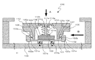
図1は、本発明の実施形態を示す振動波モータの要部断面図(駆動方向の直角断面を示す)であり、図2は、本発明の実施形態を表す振動波モータの移動方向の要部断面図である。また、本実施形態は直動型(リニア型)の振動波モータを例に説明するが、回転型やその他のタイプへの応用も可能である。
Hereinafter, embodiments of the present invention will be described in detail with reference to the accompanying drawings. In the drawings, the same parts are denoted by the same reference numerals.
Figure 1 is a fragmentary cross-sectional view of a vibration wave motor showing an embodiment of the present invention (showing the driving direction of the cross section perpendicular), FIG. 2, a main direction of movement of the vibration wave motor that represent embodiments of the present invention FIG. Further, although the present embodiment will be described by taking a direct acting (linear) vibration wave motor as an example, application to a rotary type or other types is also possible.
振動波モータ200は、振動板101を備えている。振動板101は被接合部101aを備えている。被接合部101aが基台102の接合凸部102aに対して接着などにより固定される(図2参照)。この基台102はロの字型をした枠体で構成されると共に、振動板101の厚さよりも厚い樹脂または金属で構成される。
The
また振動板101には圧電素子103が接着剤などにより固着されている。圧電素子103は高周波電圧が印加されると、振動板101が長手方向と短手方向のそれぞれの方向で共振を起こすように設定されている。なお、振動板101と圧電素子103とで振動子100を構成する。振動子100は高周波駆動電圧が印加されることで振動を起こすように構成されている。
A
その結果、図2に示すように、振動板101に形成された圧接部101bの先端が図2に示すような楕円運動を起こす。圧電素子103に印加する高周波電圧の周波数や位相を変えることで、回転方向や楕円比を適宜変化させて所望の動きを発生させることができる。これにより相手部品である摺動部材としてのスライダ104と摩擦接触することにより相対的に移動させる駆動力を発生させ、振動子100自身を光軸(図1において紙面直行方向、図2において、左右方向)を移動方向として駆動することが可能となる。スライダ104は後述するユニット支持部材116に締結手段(ネジ)によって固定されている。
As a result, as shown in FIG. 2, the tip of the pressure contact portion 101b formed on the
図1及び図2において、振動子支持部材105は、振動子100が固定された基台102と以下に示すように連結手段によって連結される。図2において転動部材であるコロ軸106は、振動板101の圧接部101bを挟んで両側に2か所設けられている。すなわち、振動子100の移動方向の前後2か所に転動部材である円筒形のローラ106が設けられている。
1 and 2, the
振動子支持部材105には図2において下方に延設された2か所の延設部105aが形成され、基台102の連結部102bと延設部105aとで形成するスペースにローラ106及び板バネ107が組み込まれる。所定の弾性を有する付勢部材である板バネ107は、基台102の連結部102bに当接し、ローラ106は、この板バネ107と延設部105aとの間に挟持され、加圧方向に移動自在である。
In the
板バネ107はローラ106の一方と共に図2において右側のスペースに組み込まれる。組み込まれた状態においては板バネ107の付勢力により、ローラ106の一方(図2において右側)を介して振動子支持部材105は図2において左方向に付勢されると共に基台102は図2において右方向に付勢される。
The
このときの付勢力は後述する振動子の加圧方向Aに対して直交する方向B(図2参照)に印加される。この結果、前述と同様に図2において左側に位置するもう一方の組み込み空間に組み込まれたローラ106も、振動子支持部材105のもう一方の延設部105aと基台102のもう一方の連結部102bとの間で挟持される。
The urging force at this time is applied in a direction B (see FIG. 2) perpendicular to the pressurizing direction A of the vibrator described later. As a result,
以上のように構成することで、移動方向(図2において左右方向)にはガタの発生が無く、後述する加圧方向A(図2において上下方向)にはローラの作用により摺動抵抗が殆ど発生しない連結手段を実現することができる。 With the configuration as described above, there is no play in the moving direction (left and right direction in FIG. 2), and almost no sliding resistance is caused by the action of the rollers in the pressing direction A (up and down direction in FIG. 2) described later. A connecting means that does not occur can be realized.
この時、板バネ107の付勢力は振動子支持部材105及び後述する被駆動部(図3における305及び306を参照)の作動開始及び停止時に発生する加減速による慣性力よりも大きくなるように設定されている。この設定により基台102及び振動子101と振動子支持部材105は、駆動時の慣性力による移動方向の相対変位が発生せず安定した駆動制御を実現することができる。
At this time, the urging force of the
加圧板108は、後述のように弾性部材109を挟んで、圧電素子103を可撓性を有して押圧保持するように構成されている。
The
加圧バネ110はバネ保持部材111及びバネ地板112との間に組み込まれ、加圧バネユニットとして構成される。この時、バネ保持部材111の先端に設けられた大径部111aはバネ地板112の嵌合部112aに遊嵌で組み込まれるので、組み立て後は加圧バネ110のバネ力に抗してユニット状態を維持できる。
The
バネ地板112の外径部には、円周方向数か所にバヨネット突部112bが形成されている。このバヨネット突部112bは組み込み状態において、振動子支持部材105に形成されたバヨネット係合部105cにより加圧方向Aの位置が規定される。この時、バネ保持部材111の先端に設けられた押圧部111bはバネ110の付勢力により加圧板108および弾性部材109を介して振動板101をスライダ104に押圧する加圧力を発生する。よって、振動子100とスライダ104とが摩擦接触することが可能となる。なお、加圧バネ110、バネ保持部材111、バネ地板112で加圧手段120を構成する。
Bayonet protrusions 112b are formed on the outer diameter portion of the
ガイド部材の一部を構成する移動板113は、振動子支持部材105の当接部105bに接着やねじ止めで固定される。移動板113にはボール114が嵌入し振動子支持部材105を光軸方向にガイドする複数のV字型の断面を有する溝部113aが形成されている(図1参照)。カバープレート115はユニット支持部材116に公知のネジにより固定される。
The moving
カバープレート115も前述のガイド部の一部を構成しており、移動板113の溝部113aに対向する位置に設けられたV字型の断面を有する溝部115aによって、ボール114を挟持する。よって、振動子支持部材105を移動方向(図1において紙面垂直方向、図2において紙面左右方向)に沿って進退可能に支持することを可能としている。以上の構成により本発明の実施形態の直動型の振動波モータが完成する。
The
ボール114を挟持する溝部113aと溝部115aは、それぞれ振動子支持部材105の駆動方向に対して直交する方向の断面がV字型の形状を有する。しかしながら、溝部113aと溝部115aは、その他の形状に形成することも可能であり、断面形状がコの字型に形成することも可能である。
Each of the
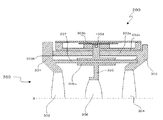
図3は本発明の実施形態の振動波モータ200が光学機器の鏡筒部350に組み込まれた時の様子を表す要部断面である。第1レンズ保持部材301は、第1のレンズ302を保持し、第3レンズ保持部材303は第3のレンズ304を保持している。第3レンズ保持部材303の外周部には筒状部303aがもうけられており、先端部303bで第1レンズ保持部材301と不図示のネジにより締結される。
FIG. 3 is a cross-sectional view of a main part showing a state when the
筒状部303aの外径部の一部には、振動波モータ200が固定されるユニット受け部303cが設けられており、ネジにより着脱自在に固定される。また筒状部303aの内径部には第2のレンズ306を保持する第2レンズ保持部材305が配置される。第2のレンズ306は光学機器の合焦レンズとして本発明の実施態様にかかる振動波モータ200により光軸X(図3参照)に沿って移動する。
A
この時、第2レンズ保持部材305はガイドバー307と軸受け部305aが相対摺動可能に嵌合しているので、第2のレンズ306は光軸Xに沿って移動することが可能となっている。第2レンズ保持部材305と振動子支持部材105との連結は、例えば振動子支持部材105に設けられた係合ピン105dと第2レンズ保持部材305に設けられた係合凹部305bとの係合によってなされる。しかしながら、公知のラックと係合ピンによって連結を行うことも可能である。
At this time, the second lens holding member 305 is fitted so that the guide bar 307 and the bearing
以上説明したように、振動子支持部材105と振動子100が固定された基台102との連結をローラ106及び板バネ107を介して行う構成とした。よって、振動子支持部材105に対して振動子100及び基台102は加圧手段120による加圧方向Aに対しては転動作用により加圧力をほぼ損失すること無く保持できる。また移動方向に対しては板バネ107の作用によりガタを発生させることなく保持されることで、光学機器の合焦レンズである第2のレンズ306が光軸Xの方向に沿って精度良く駆動制御できる。
As described above, the
以上、本発明の実施態様に関わる振動波モータ及びそれを組み込んだ光学機器の鏡筒部に関してその具体例を詳述したが、本発明は上記実施態様に限定されるものではなく、特許請求の範囲を逸脱することなくどのような形態をとることも可能である。本実施形態では、ローラ106を付勢する付勢部材として板バネ107を用いたが、ガタの発生を防止するのに必要な付勢力を与えられるものであればよく、板バネ以外の付勢部材を用いることも可能である。
Specific examples of the vibration wave motor according to the embodiment of the present invention and the lens barrel portion of the optical device incorporating the same have been described in detail, but the present invention is not limited to the above embodiment, and Any form is possible without departing from the scope. In the present embodiment, the
なお、本発明では直動駆動の振動波モータを例に説明したが、回転型の振動波モータにも適用できることは言うまでもない。また、振動波モータは、例えば振動板が超音波振動する超音波モータであっても良い。In the present invention, a direct-acting vibration wave motor has been described as an example, but it goes without saying that the present invention can also be applied to a rotary vibration wave motor. Further, the vibration wave motor may be an ultrasonic motor in which a vibration plate vibrates ultrasonically, for example.
光学機器の駆動制御を精度よく行うために用いられる。 It is used to accurately control the drive of optical equipment.
100 振動子
101 振動板
102 基台
103 圧電素子
104 スライダ
105 振動子支持部材
106 ローラ
107 板バネ
108 加圧板
109 弾性部材
110 加圧バネ
111 バネ保持部材
112 バネ地板
113 移動板
114 ボール
115 カバープレート
116 ユニット支持部材
200 振動波モータ
301 第1レンズ保持部材
302 第1のレンズ
303 第3レンズ保持部材
304 第3のレンズ
305 第2レンズ保持部材
306 第2のレンズ
307 ガイドバー
350 鏡筒部
A 加圧方向
B 加圧方向に直交する方向
100
Claims (8)
前記連結手段は、前記基台と、該基台を前記振動子支持部材に対し前記加圧手段の加圧方向に移動可能とする第1の転動部材及び第2の転動部材と、該第1の転動部材及び該第2の転動部材の配置された面のいずれか一方に設けられ、前記第1の転動部材及び前記第2の転動部材を前記加圧手段の加圧方向に直交する方向に付勢する付勢部材とを備え、前記第1の転動部材及び前記第2の転動部材が転動して、前記基台と前記振動子支持部材に対して移動可能であることを特徴とする振動波モータ。 A vibrator that vibrates by an applied high-frequency drive voltage, a sliding member that is in frictional contact with the vibrator, a pressurizing unit that pressurizes the vibrator against the sliding member, and the vibrator is fixed A base, a vibrator support member for holding the base, and a connecting means for connecting the vibrator and the vibrator support member, and the vibrator and the sliding member are relatively moved by the vibration. A moving vibration wave motor,
The connecting means includes the base, a first rolling member and a second rolling member that allow the base to move in the pressurizing direction of the pressurizing means with respect to the vibrator support member , The first rolling member and a surface on which the second rolling member is disposed are provided on one of the surfaces, and the first rolling member and the second rolling member are pressed by the pressurizing unit. A biasing member that biases in a direction perpendicular to the direction, and the first rolling member and the second rolling member roll to move relative to the base and the vibrator support member. A vibration wave motor characterized by being capable .
前記振動波モータは、前記振動子が超音波振動する超音波モータであることを特徴とする振動波モータ。 The vibration wave motor according to any one of claims 1 to 7,
The vibration wave motor is an ultrasonic motor in which the vibrator is ultrasonically vibrated.
Priority Applications (5)
| Application Number | Priority Date | Filing Date | Title |
|---|---|---|---|
| JP2013272337A JP5969976B2 (en) | 2013-12-27 | 2013-12-27 | Vibration wave motor |
| US14/548,755 US9827593B2 (en) | 2013-12-27 | 2014-11-20 | Ultrasonic motor |
| EP14194944.6A EP2889997B1 (en) | 2013-12-27 | 2014-11-26 | Ultrasonic motor |
| CN201410826655.4A CN104753390B (en) | 2013-12-27 | 2014-12-25 | Ultrasonic motor |
| RU2014153648/28A RU2596177C2 (en) | 2013-12-27 | 2014-12-26 | Ultrasonic motor |
Applications Claiming Priority (1)
| Application Number | Priority Date | Filing Date | Title |
|---|---|---|---|
| JP2013272337A JP5969976B2 (en) | 2013-12-27 | 2013-12-27 | Vibration wave motor |
Related Child Applications (1)
| Application Number | Title | Priority Date | Filing Date |
|---|---|---|---|
| JP2016135727A Division JP6347806B2 (en) | 2016-07-08 | 2016-07-08 | Motor, lens barrel and optical equipment |
Publications (3)
| Publication Number | Publication Date |
|---|---|
| JP2015126692A JP2015126692A (en) | 2015-07-06 |
| JP2015126692A5 JP2015126692A5 (en) | 2015-08-13 |
| JP5969976B2 true JP5969976B2 (en) | 2016-08-17 |
Family
ID=51987041
Family Applications (1)
| Application Number | Title | Priority Date | Filing Date |
|---|---|---|---|
| JP2013272337A Expired - Fee Related JP5969976B2 (en) | 2013-12-27 | 2013-12-27 | Vibration wave motor |
Country Status (5)
| Country | Link |
|---|---|
| US (1) | US9827593B2 (en) |
| EP (1) | EP2889997B1 (en) |
| JP (1) | JP5969976B2 (en) |
| CN (1) | CN104753390B (en) |
| RU (1) | RU2596177C2 (en) |
Cited By (3)
| Publication number | Priority date | Publication date | Assignee | Title |
|---|---|---|---|---|
| US10763763B2 (en) | 2016-04-28 | 2020-09-01 | Canon Kabushiki Kaisha | Motor and electronic apparatus including motor |
| US11190112B2 (en) | 2018-05-01 | 2021-11-30 | Canon Kabushiki Kaisha | Vibration wave motor and drive device using the same |
| US11621654B2 (en) | 2016-12-22 | 2023-04-04 | Canon Kabushiki Kaisha | Vibration-wave motor and apparatus using the same |
Families Citing this family (21)
| Publication number | Priority date | Publication date | Assignee | Title |
|---|---|---|---|---|
| JP2016213974A (en) | 2015-05-11 | 2016-12-15 | キヤノン株式会社 | Vibration type actuator and ultrasonic motor |
| JP6652794B2 (en) * | 2015-07-15 | 2020-02-26 | キヤノン株式会社 | Vibration wave motor |
| JP6708471B2 (en) * | 2016-04-21 | 2020-06-10 | キヤノン株式会社 | Vibration wave motor and optical device equipped with the vibration wave motor |
| JP6708472B2 (en) * | 2016-04-21 | 2020-06-10 | キヤノン株式会社 | Vibration wave motor and optical device equipped with the vibration wave motor |
| JP6537482B2 (en) * | 2016-10-07 | 2019-07-03 | キヤノン株式会社 | Vibration wave motor and electronic equipment |
| JP6808344B2 (en) * | 2016-04-28 | 2021-01-06 | キヤノン株式会社 | Electronic devices equipped with vibration wave motors and vibration wave motors, lens barrels, imaging devices |
| JP6808345B2 (en) * | 2016-04-28 | 2021-01-06 | キヤノン株式会社 | Electronic devices equipped with vibration wave motors and vibration wave motors, lens barrels, imaging devices |
| JP6829555B2 (en) | 2016-06-23 | 2021-02-10 | キヤノン株式会社 | Vibration wave motor and lens drive |
| JP2018064345A (en) | 2016-10-12 | 2018-04-19 | キヤノン株式会社 | Motor and electronic equipment |
| JP6849381B2 (en) | 2016-10-17 | 2021-03-24 | キヤノン株式会社 | Vibration type motors, electronic devices and imaging devices |
| US10763762B2 (en) | 2016-10-17 | 2020-09-01 | Canon Kabushiki Kaisha | Vibrator, ultrasonic motor, and optical device |
| JP6580099B2 (en) * | 2016-10-17 | 2019-09-25 | キヤノン株式会社 | Vibrator, ultrasonic motor and optical equipment |
| JP6366674B2 (en) * | 2016-12-15 | 2018-08-01 | キヤノン株式会社 | Vibration wave motor |
| JP6882036B2 (en) * | 2017-03-31 | 2021-06-02 | キヤノン株式会社 | Imaging device with vibration wave motor and vibration wave motor |
| CN112731739A (en) | 2017-05-31 | 2021-04-30 | 佳能株式会社 | Lens mount, accessory, camera mount, camera system, and image pickup apparatus |
| SG10201804096XA (en) | 2017-05-31 | 2018-12-28 | Canon Kk | Adapter device, imaging apparatus, and accessory |
| RU2747716C2 (en) | 2017-05-31 | 2021-05-13 | Кэнон Кабусики Кайся | Image capture device, accessory that can be installed on it and camera system |
| CN113347341A (en) | 2017-05-31 | 2021-09-03 | 佳能株式会社 | Accessory, image pickup apparatus capable of mounting accessory, and camera system |
| JP6968677B2 (en) * | 2017-12-06 | 2021-11-17 | キヤノン株式会社 | Drive and optical equipment |
| JP6605012B2 (en) | 2017-12-08 | 2019-11-13 | キヤノン株式会社 | Vibration wave motor and lens driving device using vibration wave motor |
| CN114427586B (en) * | 2022-01-20 | 2022-10-14 | 中南大学 | Railway roadbed dynamic energy harvesting vibration damper based on carbon neutralization concept |
Family Cites Families (24)
| Publication number | Priority date | Publication date | Assignee | Title |
|---|---|---|---|---|
| US5191688A (en) * | 1989-07-27 | 1993-03-09 | Olympus Optical Co., Ltd. | Method for producing a superior longitudinal vibrator |
| JPH0564467A (en) * | 1991-09-05 | 1993-03-12 | Canon Inc | Oscillation wave linear motor |
| JPH1090584A (en) | 1996-01-26 | 1998-04-10 | Konica Corp | Lens device |
| JP3807513B2 (en) * | 1996-02-05 | 2006-08-09 | オリンパス株式会社 | Ultrasonic linear motor |
| JPH11155290A (en) * | 1997-09-22 | 1999-06-08 | Nikon Corp | Vibration actuator |
| JP3825643B2 (en) | 2001-02-15 | 2006-09-27 | セイコーインスツル株式会社 | Ultrasonic motor and electronic device with ultrasonic motor |
| JP3828418B2 (en) * | 2001-12-21 | 2006-10-04 | アスモ株式会社 | Ultrasonic motor and stator of ultrasonic motor |
| JP4298574B2 (en) | 2004-04-20 | 2009-07-22 | サンデン株式会社 | Power transmission device |
| JP5117058B2 (en) * | 2007-01-26 | 2013-01-09 | 太平洋セメント株式会社 | Actuator case and ultrasonic motor |
| JP2008199700A (en) | 2007-02-08 | 2008-08-28 | Taiheiyo Cement Corp | Ultrasonic motor, driving method thereof, and ultrasonic motor device |
| JP2009033788A (en) * | 2007-07-24 | 2009-02-12 | Taiheiyo Cement Corp | Case for ultrasonic motor, and ultrasonic motor device |
| JP5202538B2 (en) * | 2007-10-18 | 2013-06-05 | パナソニック株式会社 | Vibration type actuator |
| JP5246919B2 (en) * | 2008-04-24 | 2013-07-24 | オリンパス株式会社 | Linear drive type ultrasonic motor |
| JP5185684B2 (en) * | 2008-04-25 | 2013-04-17 | オリンパスイメージング株式会社 | Driving device and imaging device |
| JP2010130889A (en) * | 2008-12-01 | 2010-06-10 | Olympus Corp | Linear driving type ultrasonic motor |
| JP5290781B2 (en) * | 2009-01-21 | 2013-09-18 | 太平洋セメント株式会社 | Temporary fixing jig for ultrasonic motor, case unit, and preload adjustment method for ultrasonic motor |
| JP5810303B2 (en) | 2010-04-06 | 2015-11-11 | パナソニックIpマネジメント株式会社 | Drive device |
| RU2457608C1 (en) * | 2011-01-12 | 2012-07-27 | Владимир Михайлович Нелюбов | Indexing performance method and device for its implementation (versions) |
| DE102011082200A1 (en) | 2011-09-06 | 2013-03-07 | Physik Instrumente (Pi) Gmbh & Co. Kg | ultrasonic motor |
| JP5942403B2 (en) * | 2011-12-06 | 2016-06-29 | セイコーエプソン株式会社 | Piezoelectric motor, drive device, electronic component inspection device, electronic component transport device, printing device, robot hand, and robot |
| JP2013179733A (en) | 2012-02-28 | 2013-09-09 | Tamron Co Ltd | Vibrating body holding mechanism, ultrasonic motor, and lens driving device |
| JP2013255959A (en) | 2012-06-12 | 2013-12-26 | Seiko Epson Corp | Moving mechanism, electronic component transport device, and electronic component inspection device |
| EP2680334A1 (en) | 2012-06-28 | 2014-01-01 | Leica Geosystems AG | Piezo drive with piezo oscillator with a pivoting bearing |
| JP2014220988A (en) * | 2013-04-12 | 2014-11-20 | キヤノン株式会社 | Vibration type driving device |
-
2013
- 2013-12-27 JP JP2013272337A patent/JP5969976B2/en not_active Expired - Fee Related
-
2014
- 2014-11-20 US US14/548,755 patent/US9827593B2/en active Active
- 2014-11-26 EP EP14194944.6A patent/EP2889997B1/en active Active
- 2014-12-25 CN CN201410826655.4A patent/CN104753390B/en active Active
- 2014-12-26 RU RU2014153648/28A patent/RU2596177C2/en active
Cited By (4)
| Publication number | Priority date | Publication date | Assignee | Title |
|---|---|---|---|---|
| US10763763B2 (en) | 2016-04-28 | 2020-09-01 | Canon Kabushiki Kaisha | Motor and electronic apparatus including motor |
| US11621654B2 (en) | 2016-12-22 | 2023-04-04 | Canon Kabushiki Kaisha | Vibration-wave motor and apparatus using the same |
| US11190112B2 (en) | 2018-05-01 | 2021-11-30 | Canon Kabushiki Kaisha | Vibration wave motor and drive device using the same |
| DE102019110962B4 (en) | 2018-05-01 | 2022-09-29 | Canon Kabushiki Kaisha | Vibration wave motor and drive device using it |
Also Published As
| Publication number | Publication date |
|---|---|
| US9827593B2 (en) | 2017-11-28 |
| JP2015126692A (en) | 2015-07-06 |
| EP2889997B1 (en) | 2018-11-14 |
| US20150183001A1 (en) | 2015-07-02 |
| CN104753390A (en) | 2015-07-01 |
| RU2596177C2 (en) | 2016-08-27 |
| CN104753390B (en) | 2018-04-27 |
| EP2889997A1 (en) | 2015-07-01 |
| RU2014153648A (en) | 2016-07-20 |
Similar Documents
| Publication | Publication Date | Title |
|---|---|---|
| JP5969976B2 (en) | Vibration wave motor | |
| JP2015126692A5 (en) | ||
| JP6188366B2 (en) | Actuator and optical equipment | |
| JP5955347B2 (en) | Linear ultrasonic motor and optical apparatus using the same | |
| KR101555903B1 (en) | Motor and lens apparatus including the same | |
| KR101818059B1 (en) | Linear vibration-wave motor | |
| JP6808345B2 (en) | Electronic devices equipped with vibration wave motors and vibration wave motors, lens barrels, imaging devices | |
| JP6271963B2 (en) | Vibration type actuator | |
| JP6366674B2 (en) | Vibration wave motor | |
| JP6806472B2 (en) | Vibration wave motor and optical equipment to which the vibration wave motor is applied | |
| JP6257224B2 (en) | Motor and lens device | |
| JP6347806B2 (en) | Motor, lens barrel and optical equipment | |
| JP2016082802A (en) | Driving device including vibration wave motor | |
| JP6882036B2 (en) | Imaging device with vibration wave motor and vibration wave motor | |
| US10333432B2 (en) | Vibration type actuator and ultrasonic motor | |
| JP6257281B2 (en) | Ultrasonic actuator | |
| JP6271901B2 (en) | Ultrasonic motor and optical apparatus equipped with ultrasonic motor | |
| JP6808344B2 (en) | Electronic devices equipped with vibration wave motors and vibration wave motors, lens barrels, imaging devices | |
| JP5932434B2 (en) | Ultrasonic motor and device driving apparatus with ultrasonic motor | |
| JP6708471B2 (en) | Vibration wave motor and optical device equipped with the vibration wave motor | |
| JP2018019518A (en) | Vibration wave motor and optical instrument having vibration wave motor | |
| JP2019201465A (en) | Vibration wave motor and drive device | |
| JP2019083664A (en) | Vibration wave motor, lens device, and imaging apparatus | |
| JP2016103939A (en) | Vibration type actuator and ultrasonic motor |
Legal Events
| Date | Code | Title | Description |
|---|---|---|---|
| A521 | Request for written amendment filed |
Free format text: JAPANESE INTERMEDIATE CODE: A523 Effective date: 20150618 |
|
| A621 | Written request for application examination |
Free format text: JAPANESE INTERMEDIATE CODE: A621 Effective date: 20150618 |
|
| A977 | Report on retrieval |
Free format text: JAPANESE INTERMEDIATE CODE: A971007 Effective date: 20151030 |
|
| A131 | Notification of reasons for refusal |
Free format text: JAPANESE INTERMEDIATE CODE: A131 Effective date: 20151110 |
|
| A521 | Request for written amendment filed |
Free format text: JAPANESE INTERMEDIATE CODE: A523 Effective date: 20160112 |
|
| TRDD | Decision of grant or rejection written | ||
| A01 | Written decision to grant a patent or to grant a registration (utility model) |
Free format text: JAPANESE INTERMEDIATE CODE: A01 Effective date: 20160609 |
|
| A61 | First payment of annual fees (during grant procedure) |
Free format text: JAPANESE INTERMEDIATE CODE: A61 Effective date: 20160708 |
|
| R151 | Written notification of patent or utility model registration |
Ref document number: 5969976 Country of ref document: JP Free format text: JAPANESE INTERMEDIATE CODE: R151 |
|
| LAPS | Cancellation because of no payment of annual fees |