JP5967045B2 - Treatment liquid supply apparatus and treatment liquid supply method - Google Patents
Treatment liquid supply apparatus and treatment liquid supply method Download PDFInfo
- Publication number
- JP5967045B2 JP5967045B2 JP2013207748A JP2013207748A JP5967045B2 JP 5967045 B2 JP5967045 B2 JP 5967045B2 JP 2013207748 A JP2013207748 A JP 2013207748A JP 2013207748 A JP2013207748 A JP 2013207748A JP 5967045 B2 JP5967045 B2 JP 5967045B2
- Authority
- JP
- Japan
- Prior art keywords
- pump
- processing liquid
- filter device
- discharge
- liquid
- Prior art date
- Legal status (The legal status is an assumption and is not a legal conclusion. Google has not performed a legal analysis and makes no representation as to the accuracy of the status listed.)
- Active
Links
- 239000007788 liquid Substances 0.000 title claims description 342
- 238000000034 method Methods 0.000 title claims description 106
- 238000012545 processing Methods 0.000 claims description 208
- 230000008569 process Effects 0.000 claims description 84
- 230000007246 mechanism Effects 0.000 claims description 40
- 238000007872 degassing Methods 0.000 claims description 38
- 230000006837 decompression Effects 0.000 claims description 27
- 238000007599 discharging Methods 0.000 claims description 14
- 238000003860 storage Methods 0.000 claims description 11
- 230000009467 reduction Effects 0.000 claims description 2
- 235000012431 wafers Nutrition 0.000 description 73
- 238000001914 filtration Methods 0.000 description 37
- 239000007789 gas Substances 0.000 description 31
- 239000002245 particle Substances 0.000 description 25
- 238000000576 coating method Methods 0.000 description 14
- 238000012546 transfer Methods 0.000 description 14
- 239000011248 coating agent Substances 0.000 description 13
- 238000010521 absorption reaction Methods 0.000 description 9
- 238000010586 diagram Methods 0.000 description 9
- 239000012528 membrane Substances 0.000 description 7
- 238000010926 purge Methods 0.000 description 6
- 230000007704 transition Effects 0.000 description 6
- 238000013022 venting Methods 0.000 description 6
- 238000011144 upstream manufacturing Methods 0.000 description 5
- 238000001816 cooling Methods 0.000 description 4
- 238000010438 heat treatment Methods 0.000 description 4
- 230000007423 decrease Effects 0.000 description 3
- 238000000206 photolithography Methods 0.000 description 3
- 239000004065 semiconductor Substances 0.000 description 3
- 239000000758 substrate Substances 0.000 description 3
- IJGRMHOSHXDMSA-UHFFFAOYSA-N Atomic nitrogen Chemical compound N#N IJGRMHOSHXDMSA-UHFFFAOYSA-N 0.000 description 2
- 230000008859 change Effects 0.000 description 2
- 238000001514 detection method Methods 0.000 description 2
- 230000000694 effects Effects 0.000 description 2
- 238000007781 pre-processing Methods 0.000 description 2
- 230000000717 retained effect Effects 0.000 description 2
- 239000000969 carrier Substances 0.000 description 1
- 238000004140 cleaning Methods 0.000 description 1
- 230000003247 decreasing effect Effects 0.000 description 1
- 230000007547 defect Effects 0.000 description 1
- 230000003111 delayed effect Effects 0.000 description 1
- 238000011161 development Methods 0.000 description 1
- 229910001873 dinitrogen Inorganic materials 0.000 description 1
- 238000005516 engineering process Methods 0.000 description 1
- 239000007888 film coating Substances 0.000 description 1
- 238000009501 film coating Methods 0.000 description 1
- 238000005187 foaming Methods 0.000 description 1
- 239000011521 glass Substances 0.000 description 1
- 239000012510 hollow fiber Substances 0.000 description 1
- 238000007654 immersion Methods 0.000 description 1
- 239000011261 inert gas Substances 0.000 description 1
- 238000004519 manufacturing process Methods 0.000 description 1
- 230000004048 modification Effects 0.000 description 1
- 238000012986 modification Methods 0.000 description 1
- 239000004745 nonwoven fabric Substances 0.000 description 1
- 238000005192 partition Methods 0.000 description 1
- 230000002093 peripheral effect Effects 0.000 description 1
- 229920002120 photoresistant polymer Polymers 0.000 description 1
- 229920000098 polyolefin Polymers 0.000 description 1
- 238000012805 post-processing Methods 0.000 description 1
- 230000002441 reversible effect Effects 0.000 description 1
- 239000000126 substance Substances 0.000 description 1
- BFKJFAAPBSQJPD-UHFFFAOYSA-N tetrafluoroethene Chemical group FC(F)=C(F)F BFKJFAAPBSQJPD-UHFFFAOYSA-N 0.000 description 1
- 239000002699 waste material Substances 0.000 description 1
Images


Classifications
-
- H—ELECTRICITY
- H01—ELECTRIC ELEMENTS
- H01L—SEMICONDUCTOR DEVICES NOT COVERED BY CLASS H10
- H01L21/00—Processes or apparatus adapted for the manufacture or treatment of semiconductor or solid state devices or of parts thereof
- H01L21/02—Manufacture or treatment of semiconductor devices or of parts thereof
- H01L21/027—Making masks on semiconductor bodies for further photolithographic processing not provided for in group H01L21/18 or H01L21/34
- H01L21/0271—Making masks on semiconductor bodies for further photolithographic processing not provided for in group H01L21/18 or H01L21/34 comprising organic layers
- H01L21/0273—Making masks on semiconductor bodies for further photolithographic processing not provided for in group H01L21/18 or H01L21/34 comprising organic layers characterised by the treatment of photoresist layers
- H01L21/0274—Photolithographic processes
-
- H—ELECTRICITY
- H01—ELECTRIC ELEMENTS
- H01L—SEMICONDUCTOR DEVICES NOT COVERED BY CLASS H10
- H01L21/00—Processes or apparatus adapted for the manufacture or treatment of semiconductor or solid state devices or of parts thereof
- H01L21/67—Apparatus specially adapted for handling semiconductor or electric solid state devices during manufacture or treatment thereof; Apparatus specially adapted for handling wafers during manufacture or treatment of semiconductor or electric solid state devices or components ; Apparatus not specifically provided for elsewhere
- H01L21/67005—Apparatus not specifically provided for elsewhere
- H01L21/67011—Apparatus for manufacture or treatment
- H01L21/67017—Apparatus for fluid treatment
Landscapes
- Engineering & Computer Science (AREA)
- General Physics & Mathematics (AREA)
- Physics & Mathematics (AREA)
- Microelectronics & Electronic Packaging (AREA)
- Manufacturing & Machinery (AREA)
- Computer Hardware Design (AREA)
- Condensed Matter Physics & Semiconductors (AREA)
- Power Engineering (AREA)
- Coating Apparatus (AREA)
- Exposure Of Semiconductors, Excluding Electron Or Ion Beam Exposure (AREA)
- Degasification And Air Bubble Elimination (AREA)
- Filtration Of Liquid (AREA)
- Cleaning Or Drying Semiconductors (AREA)
Description
この発明は、例えば半導体ウエハやLCD用ガラス基板等の被処理体に処理液を供給して処理する処理液供給装置及び処理液供給方法に関する。 The present invention relates to a processing liquid supply apparatus and a processing liquid supply method for supplying a processing liquid to an object to be processed such as a semiconductor wafer or an LCD glass substrate.
一般に、半導体デバイスの製造のフォトリソグラフィ技術においては、半導体ウエハやFPD基板等(以下にウエハ等という)にフォトレジストを塗布し、これにより形成されたレジスト膜を所定の回路パターンに応じて露光し、この露光パターンを現像処理することによりレジスト膜に回路パターンが形成されている。 In general, in photolithography technology for manufacturing semiconductor devices, a photoresist is applied to a semiconductor wafer, FPD substrate or the like (hereinafter referred to as a wafer), and the resist film formed thereby is exposed according to a predetermined circuit pattern. The circuit pattern is formed on the resist film by developing the exposure pattern.
このようなフォトリソグラフィ工程において、ウエハ等に供給されるレジスト液や現像液等の処理液には、様々な原因によって窒素ガス等の気泡やパーティクル(異物)が混入する虞があり、気泡やパーティクルが混在した処理液がウエハ等に供給されると塗布ムラや欠陥が発生する虞がある。このため、処理液中に混在する気泡やパーティクルを除去するための装置が処理液の管路に介設されている。 In such a photolithography process, bubbles or particles (foreign matter) such as nitrogen gas may be mixed into a processing solution such as a resist solution or a developer supplied to a wafer or the like due to various causes. If a processing liquid in which is mixed is supplied to a wafer or the like, coating unevenness or defects may occur. For this reason, an apparatus for removing bubbles and particles mixed in the processing liquid is interposed in the processing liquid pipe.
従来、この種の装置として、供給ノズルと処理液貯留容器とを接続する供給管路に一時貯留容器とフィルタとポンプを介設し、処理液貯留容器と一時貯留容器との間の供給管路及びフィルタに接続する循環管路と、循環管路に設けられた可変絞りを有する処理液供給装置が知られている(例えば、特許文献1参照)。この処理液供給装置は、フォトリソグラフィ工程で行われる処理の効率、多様化を図るため、複数の供給ノズルを備えており、目的に応じて供給ノズルを選択して使用している Conventionally, as this type of apparatus, a temporary storage container, a filter, and a pump are interposed in a supply pipe line that connects a supply nozzle and a processing liquid storage container, and a supply pipe line between the processing liquid storage container and the temporary storage container A processing liquid supply apparatus having a circulation line connected to the filter and a variable throttle provided in the circulation line is known (see, for example, Patent Document 1). This processing liquid supply apparatus is provided with a plurality of supply nozzles in order to improve the efficiency and diversification of processing performed in the photolithography process, and the supply nozzles are selected and used according to the purpose.
この処理液供給装置においては、フィルタで泡抜きされた処理液の液圧が可変絞りによって低下することで処理液に溶存する気体が気泡化され、この気泡が循環経路から供給管路を介して再びフィルタを通過することで除去される。そのため、処理液中に溶存する気体を効率的に除去することができる。 In this processing liquid supply apparatus, the gas dissolved in the processing liquid is bubbled by reducing the liquid pressure of the processing liquid bubbled out by the filter by the variable throttle, and the bubbles are passed from the circulation path through the supply pipe. It is removed by passing through the filter again. Therefore, the gas dissolved in the processing liquid can be efficiently removed.
ところで、複数の供給管路を備える処理液供給装置では、使用していない供給ノズルと接続する供給管路に介設されるフィルタで処理液の滞留が生じる。ここで、フィルタ等の容量の大きい場所で処理液を長時間滞留させると、特にフィルタに滞留している気泡やゲルがフィルタと処理液との界面でパーティクルとして成長・増加する傾向が見られる。そのため、処理液中に混在するパーティクルの増加を防止する方法として、処理液の吐出をウエハ等以外の場所に定期的に行うことで、フィルタ等の容量の大きい場所で処理液を長時間滞留させないようにする方法が考えられる(ダミー吐出)。しかしながら、ダミー吐出では吐出した処理液を廃棄することになるため、処理液の消費量が増大するという問題がある。また、上記特許文献1の処理液供給装置においては、気泡をフィルタで除去するため、気泡がフィルタ装置に残留し、フィルタ装置の性能を低下させる可能性がある。
By the way, in the processing liquid supply apparatus including a plurality of supply pipes, the processing liquid is retained by a filter interposed in the supply pipe connected to the unused supply nozzle. Here, when the treatment liquid is retained for a long time in a place with a large capacity, such as a filter, there is a tendency that bubbles and gel staying in the filter grow and increase as particles at the interface between the filter and the treatment liquid. Therefore, as a method of preventing the increase of particles mixed in the processing liquid, the processing liquid is regularly discharged to a place other than the wafer etc. so that the processing liquid does not stay in a place with a large capacity such as a filter for a long time. A method of doing so is conceivable (dummy discharge). However, since the discharged processing liquid is discarded in the dummy discharge, there is a problem that the consumption amount of the processing liquid increases. Further, in the processing liquid supply apparatus of
この発明は、上記事情に鑑みてなされたもので、処理液を無駄に消費することなく、処理液中のパーティクルの増加を効率的に抑制することを目的とする。 The present invention has been made in view of the above circumstances, and an object thereof is to efficiently suppress an increase in particles in a processing liquid without wasting the processing liquid wastefully.
本発明の処理液供給装置は、被処理体を処理するための処理液を供給する処理液供給源と、
前記処理液供給源に供給路を介して接続され、前記処理液を被処理体に吐出する吐出部と、
前記供給路に設けられ、処理液中の異物を除去するためのフィルタ装置と、
前記供給路におけるフィルタ装置の一次側及び二次側に夫々設けられた供給ポンプ及び吐出ポンプと、
前記処理液供給源から供給された処理液を、前記供給ポンプ及び吐出ポンプの少なくとも一方を用いて減圧して脱気し、次いで脱気された処理液を前記供給ポンプ及び吐出ポンプを用いて前記フィルタ装置の一次側から当該フィルタ装置を介して二次側へ通過させるように制御信号を出力する制御部と、を備えたことを特徴とする。
The processing liquid supply apparatus of the present invention includes a processing liquid supply source that supplies a processing liquid for processing a target object,
A discharge unit connected to the processing liquid supply source via a supply path, and discharging the processing liquid to a target object;
A filter device provided in the supply path for removing foreign matter in the processing liquid;
A supply pump and a discharge pump respectively provided on the primary side and the secondary side of the filter device in the supply path;
The processing liquid supplied from the processing liquid supply source is degassed by depressurizing it using at least one of the supply pump and the discharge pump, and then the degassed processing liquid is stored using the supply pump and the discharge pump. And a control unit that outputs a control signal so as to pass from the primary side of the filter device to the secondary side via the filter device.
本発明の他の処理液供給装置は、
被処理体を処理するための処理液を供給する処理液供給源と、
前記処理液供給源に供給路を介して接続され、前記処理液を被処理体に吐出する吐出部と、
前記供給路に設けられ、処理液中の異物を除去するためのフィルタ装置と、
前記処理液供給源から供給された処理液を脱気する脱気機構と、
前記脱気機構により脱気された処理液を前記フィルタ装置の一次側から当該フィルタ装置を介して二次側へ通過させるための送液用のポンプと、を備え、
前記脱気機構は、処理液を減圧する減圧機構を備え
前記減圧機構は、処理液を吸引して減圧空間を形成するための減圧用のポンプを含み、
前記減圧用のポンプの吐出側を閉じ、吸入側を開いて吸入動作を行うように制御信号を出力する制御部を設けたことを特徴とする。
Another treatment liquid supply apparatus of the present invention is
A processing liquid supply source for supplying a processing liquid for processing the object to be processed;
A discharge unit connected to the processing liquid supply source via a supply path, and discharging the processing liquid to a target object;
A filter device provided in the supply path for removing foreign matter in the processing liquid;
A degassing mechanism for degassing the processing liquid supplied from the processing liquid supply source;
A liquid feed pump for passing the processing liquid degassed by the degassing mechanism from the primary side of the filter device to the secondary side via the filter device ,
The deaeration mechanism includes a decompression mechanism that decompresses the processing liquid.
The decompression mechanism includes a decompression pump for sucking the processing liquid to form a decompression space;
A control unit is provided that outputs a control signal to close the discharge side of the decompression pump and open the suction side to perform the suction operation .
本発明によれば、脱気機構により脱気された処理液を、フィルタ装置の一次側から二次側へ通過させる。フィルタ装置に含まれる気泡は、前記処理液に効率よく溶解され、当該フィルタ装置の二次側へと効率良く除去される。従って、フィルタ装置に通液して廃棄する処理液の量が抑えられる。また、フィルタ装置に残留する気泡がパーティクルとなって被処理体に吐出される処理液中に混入することを効率的に抑えることができる。 According to the present invention, the processing liquid deaerated by the deaeration mechanism is passed from the primary side to the secondary side of the filter device. Air bubbles contained in the filter device are efficiently dissolved in the treatment liquid and efficiently removed to the secondary side of the filter device. Therefore, the amount of the processing liquid that is passed through the filter device and discarded is suppressed. Moreover, it can suppress efficiently that the bubble which remains in a filter apparatus becomes a particle, and mixes in the process liquid discharged to a to-be-processed object.
以下、この発明の実施形態について、添付図面に基づいて説明する。ここでは、この発明に係る処理液供給装置(レジスト液処理装置)を塗布・現像装置に適用した場合について説明する。 Embodiments of the present invention will be described below with reference to the accompanying drawings. Here, the case where the processing liquid supply apparatus (resist liquid processing apparatus) according to the present invention is applied to a coating / developing apparatus will be described.
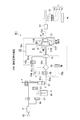
上記塗布・現像装置は、図1及び図2に示すように、基板であるウエハWを複数枚例えば25枚密閉収納するキャリア10を搬出入するためのキャリアステーション1と、このキャリアステーション1から取り出されたウエハWにレジスト塗布,現像処理等を施す処理部2と、当該処理部2とウエハWの表面に光を透過する液層を形成した状態でウエハWの表面を液浸露光する露光部4との間でウエハWの受け渡しを行うインターフェース部3とを具備している。
As shown in FIGS. 1 and 2, the coating / developing apparatus takes out a
キャリアステーション1には、キャリア10を複数個並べて載置可能な載置部11と、この載置部11から見て前方の壁面に設けられる開閉部12と、開閉部12を介してキャリア10からウエハWを取り出すための受け渡し手段A1とが設けられている。
The
インターフェース部3は、処理部2と露光部4との間に前後に設けられる第1の搬送室3A及び第2の搬送室3Bにて構成されており、それぞれに第1のウエハ搬送部30A及び第2のウエハ搬送部30Bが設けられている。
The
また、キャリアステーション1の奥側には筐体20にて周囲を囲まれる処理部2が接続されており、この処理部2には手前側から順に加熱・冷却系のユニットを多段化した棚ユニットU1,U2,U3及び液処理ユニットU4,U5の各ユニット間のウエハWの受け渡しを行う主搬送手段A2,A3が交互に配列して設けられている。また、主搬送手段A2,A3は、キャリアステーション1から見て前後方向に配置される棚ユニットU1,U2,U3側の一面部と、後述する例えば右側の液処理ユニットU4,U5側の一面部と、左側の一面をなす背面部とで構成される区画壁21により囲まれる空間内に配置されている。また、キャリアステーション1と処理部2との間、処理部2とインターフェース部3との間には、各ユニットで用いられる処理液の温度調節装置や温湿度調節用のダクト等を
備えた温湿度調節ユニット22が配置されている。
Further, a
棚ユニットU1,U2,U3は、液処理ユニットU4,U5にて行われる処理の前処理及び後処理を行うための各種ユニットを複数段例えば10段に積層した構成とされており、その組み合わせはウエハWを加熱(ベーク)する加熱ユニット(図示せず)、ウエハWを冷却する冷却ユニット(図示せず)等が含まれる。また、ウエハWに所定の処理液を供給して処理を行う液処理ユニットU4,U5は、例えば図1に示すように、レジストや現像液などの薬液収納部14の上に反射防止膜を塗布する反射防止膜塗布ユニット(BCT)23,ウエハWにレジスト液を塗布する塗布ユニット(COT)24、ウエハWに現像液を供給して現像処理する現像ユニット(DEV)25等を複数段例えば5段に積層して構成されている。塗布ユニット(COT)24は、前記レジスト液供給装置である。
The shelf units U1, U2, and U3 are configured such that various units for performing pre-processing and post-processing of the processing performed in the liquid processing units U4 and U5 are stacked in a plurality of stages, for example, 10 stages. A heating unit (not shown) for heating (baking) the wafer W, a cooling unit (not shown) for cooling the wafer W, and the like are included. Further, in the liquid processing units U4 and U5 that perform processing by supplying a predetermined processing liquid to the wafer W, for example, as shown in FIG. 1, an antireflection film is applied on a chemical
上記のように構成される塗布・現像処理装置におけるウエハの流れの一例について、図1及び図2を参照しながら簡単に説明する。塗布、現像処理装置では、ロットごとにウエハWが連続して搬送される。つまり、同じロットのウエハWが続けて搬送される。まず、例えば25枚のウエハWを収納したキャリア10が載置部11に載置されると、開閉部12と共にキャリア10の蓋体が外されて受け渡し手段A1によりウエハWが取り出される。そして、ウエハWは棚ユニットU1の一段をなす受け渡しユニット(図示せず)を介して主搬送手段A2へと受け渡され、塗布処理の前処理として例えば反射防止膜形成処理、冷却処理が行われた後、塗布ユニット(COT)24にてレジスト液が塗布される。次いで、主搬送手段A2によりウエハWは棚ユニットU1〜U3の一の棚をなす加熱ユニットで加熱(ベーク処理)され、更に冷却された後棚ユニットU3の受け渡しユニットを経由してインターフェース部3へと搬入される。このインターフェース部3において、第1の搬送室3A及び第2の搬送室3Bの第1のウエハ搬送部30A及び第2のウエハ搬送部30Bによって露光部4に搬送され、ウエハWの表面に対向するように露光手段(図示せず)が配置されて露光が行われる。露光後、ウエハWは逆の経路で主搬送手段A2まで搬送され、現像ユニット(DEV)25にて現像されることでパターンが形成される。しかる後ウエハWは載置部11上に載置された元のキャリア10へと戻される。
An example of the wafer flow in the coating / developing apparatus configured as described above will be briefly described with reference to FIGS. In the coating and developing apparatus, the wafers W are continuously transferred for each lot. That is, the wafers W of the same lot are continuously transferred. First, for example, when the
<第1実施形態>
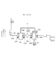
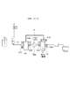
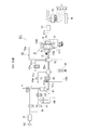
次に、この発明に係る処理液供給装置の第1実施形態について図3を参照しながら説明する。第1の実施形態に係るレジスト液供給装置5は、複数のレジスト液供給系500により構成されている。レジスト液供給系500は、処理液であるレジスト液Lを貯留するレジスト容器60と、当該レジスト容器60とウエハWにレジスト液Lを吐出(供給)するためのノズルとを接続する処理液供給管路51と、を備える。また、レジスト液供給系500は、処理液供給管路51に介設され、レジスト液Lを濾過してパーティクルを除去すると共に、レジスト液L中に混入している気泡やパーティクルなどの異物を除去するフィルタ装置52aを備える。さらに、レジスト液供給系500は、前記フィルタ装置52aの一次側、二次側の処理液供給管路51に夫々介設されるポンプP1、P2と、前記ポンプP2の二次側の処理液供給管路51に介設される供給制御弁57と、前記ポンプP1の一次側の処理液供給管路51に介設されるバッファタンク61と、を具備する。
<First Embodiment>
Next, a first embodiment of the processing liquid supply apparatus according to the present invention will be described with reference to FIG. The resist
前記処理液供給管路51は、処理液供給源である前記レジスト容器60と当該レジスト容器60から導かれた処理液を一時貯留する前記バッファタンク61とを接続する第1の処理液供給管路51aと、当該バッファタンク61とノズルとを接続する第2の処理液供給管路51bと、から構成される。つまり、上記のフィルタ装置52a、ポンプP1、P2及び供給制御弁57は、第2の処理液供給管路51bに介設されている。また、ポンプP1、P2は、この処理液供給管路51bの他に、帰還用管路(循環路)55によって互いに接続されている。
The processing
前記ポンプP1は、フィルタ装置52aへレジスト液Lを供給するためのポンプであり、説明の便宜上、供給ポンプP1と記載する場合がある。ポンプP2はウエハWの液処理時に、レジスト液LをウエハWに吐出させるノズルへ送液するものであるため、説明の便宜上、吐出ポンプP2と記載する場合がある。図4には、前記供給ポンプP1の概略縦断面図を示している。供給ポンプP1は下側が開口した筐体101と、当該筐体101の下方側を塞ぐように形成されたダイヤフラム102と、を備えている。ダイヤフラム102は、この例では上側が塞がれた筒の外縁部が上方に折り返されて、前記筐体101の縁部に接続されている。
The pump P1 is a pump for supplying the resist solution L to the
当該筐体101とダイヤフラム102とによって、レジスト液Lが貯留されるポンプ室103が形成される。図中104は駆動機構であり、当該駆動機構104により、図4上段、下段に夫々示すようにダイヤフラム102が変形して、ポンプ室103の容積が変化する。それによって、ポンプ室103からのレジスト液Lの吐出動作と、ポンプ室103へのレジスト液Lの吸液動作とを行うことができる。
The
供給ポンプP1の吸入側(一次側)には、第2の処理液供給管路51bから当該供給ポンプP1への処理液Lの流入を可能にする電磁式の開閉弁V31が設けられている。供給ポンプP1の吐出側(二次側)には電磁式の開閉弁V32が設けられている。また、前記帰還用管路55の下流端が、前記ポンプ室103に接続されている。
On the suction side (primary side) of the supply pump P1, an electromagnetic on-off valve V31 that allows the processing liquid L to flow into the supply pump P1 from the second processing
吐出ポンプP2は、供給ポンプP1と略同様に構成されている。差異点としては、図3に示すように開閉弁V33が設けられ、この開閉弁V33を介して前記帰還用管路55の上流端が接続されていることである。また、吐出ポンプP2には、当該吐出ポンプP2におけるポンプ室103の圧力を検出するセンサ105が設けられている。センサ105により検出される圧力に基づいて、コントローラ200により、前記駆動機構104を介してポンプP1、P2の動作が制御される。なお、開閉弁により互いに区画されていないときにポンプP1、P2の各ポンプ室103の圧力は、同様に変化するので、前記センサ105は供給ポンプP1のポンプ室103の圧力を検出するためのものでもある。ただし、ポンプP1にもセンサ105を設けて、夫々のセンサ105の検出結果によりポンプ室103の圧力を制御してもよい。また、供給ポンプP1の開閉弁V31、V32に対応する吐出ポンプP2の開閉弁を、図3において開閉弁V34、V35として示している。
The discharge pump P2 is configured in substantially the same manner as the supply pump P1. The difference is that an on-off valve V33 is provided as shown in FIG. 3, and the upstream end of the
前記供給制御弁57としては、例えば、ディスペンスバルブを備えた流量制御弁が用いられる。また図中70は、前記ノズルにより構成されるノズルユニットである。当該ノズルユニット70には、各々個別のレジスト液供給系500と接続される複数本(図面では4本の場合を示す)のノズルが設けられている。図中各ノズルを7(7a〜7d)として示しており、これらノズル7a〜7dに接続される各レジスト液供給系500の前記レジスト容器60には、互いに異なる種類のレジスト液Lが貯留されている。従って、各処理液供給ノズル7a〜7dから互いに異なるレジスト液LをウエハWに吐出することができる。コントローラ200により、ウエハWのロット毎に吐出されるレジスト液L、即ち使用されるレジスト液供給系500が選択される。
As the
レジスト容器60の上部には、不活性ガス例えば窒素(N2)ガスの供給源62と接続する第1の気体供給管路8aが接続されている。また、この第1の気体供給管路8aには、可変調整可能な圧力調整手段である電空レギュレータRが介設されている。この電空レギュレータRは、コントローラ200からの制御信号によって作動する操作部例えば比例ソレノイドと、該ソレノイドの作動によって開閉する弁機構とを具備しており、弁機構の開閉によって圧力を調整するように構成されている。
Connected to the upper portion of the resist
上記第1の気体供給管路8aにおいて、電空レギュレータRとレジスト容器60との間には電磁式の切換弁V1が介設されている。また、第1の処理液供給管路51aのレジスト容器60とバッファタンク61との間には電磁式の切換弁V2が介設されている。切換弁V1は、レジスト容器60内を、大気雰囲気に開放された状態、ガス供給源62に接続された状態、前記大気雰囲気及びガス供給源62から遮断された状態のうち、いずれかの状態に切り替える。これら切換弁V1、V2及び電空レギュレータRも、各々レジスト液供給系500を構成する。例えばガス供給源62は、各レジスト液供給系500に共用される。
In the first
バッファタンク61には、その内部のレジスト液Lの上限液面及び下限液面を検知する上限液面センサ61a及び下限液面センサ61bが設けられており、これら上限液面センサ61a及び下限液面センサ61bによって検知された信号がコントローラ200に伝達されるように形成されている。この検知信号に基づいて、レジスト容器60からレジスト液Lが供給され、バッファタンク61内の液面が制御される。また、バッファタンク61の上部には、バッファタンク61内の気層及びタンク61内のレジスト液を除去するためのドレイン管路61cが設けられ、当該ドレイン管路61cには電磁式の切換弁V6aが介設されている。
The
フィルタ装置52aの上部には、フィルタ装置52a内の気相雰囲気を除去(ベント)するためのベント用管路51cが設けられ、当該ベント用管路51cには電磁式の切換弁V4aが介設されている。
図5に基づいて、フィルタ装置52aの構成について説明する。フィルタ装置52aは、円筒状に形成されたフィルタ52fと、フィルタ52fを囲むように保持する保持部52iと、外壁部52oとから主に構成されている。また、フィルタ52fの内周側には、濾過されたレジスト液Lが満たされる空間部52sが設けられている。フィルタ装置52aの外壁部52oと保持部52iとの間には、レジスト液通路52pが設けられている。また、レジスト液通路52pの二次側はフィルタ52fを介して空間部52sと連通している。また、空間部52sの一次側及び二次側は第2の処理液供給管路51bと連通し、レジスト液通路52pの二次側は前記ベント用管路51cと連通している。
A
Based on FIG. 5, the structure of the
このフィルタ装置52aは、処理液供給管路51b及びベント用管路51cから取り外し可能であり、交換自在に構成されている。また、上記のフィルタ52fは、例えば不織布により構成される膜部材により構成されており、多数の微細な孔を備えている。このフィルタ52fは、フィルタ装置52aをレジスト液供給系500に取り付ける際は乾燥しているが、取付け後はレジスト液Lに浸され、各孔にレジスト液が通流されて、各孔に含まれていた気泡及びパーティクルが除去されて使用される。それによって、フィルタ52f自体に含まれる異物(気泡及びパーティクル)によりウエハWに供給されるレジスト液が汚染されることを防ぐ。また、前記孔へのレジスト液の充填率が高い、つまり前記気泡の除去率が高いほど、ウエハWにレジスト液Lを供給するにあたり、フィルタ52fの一次側のレジスト液Lは、フィルタ52fの二次側へ移動するまでにより多くの孔を通過することになり、前記レジスト液Lに含まれる異物はフィルタ52fの二次側へと通過し難くなる。つまり、フィルタ52fの異物の除去性能が向上することになる。
The
そこで、レジスト液供給系500では、当該供給系中に減圧雰囲気を形成して、その供給系におけるレジスト液Lを脱気し、そのように脱気したレジスト液Lをフィルタ52fの一次側から二次側へ通流させて、フィルタ52fの前記気泡を除去する脱気液供給処理が行われる。この処理では、脱気されたレジスト液が供給されることで、フィルタ52fの前記孔内の気泡は、当該レジスト液中に効率よく溶け込み、当該孔内にレジスト液が通流される。そして、溶け込んだ気泡は、レジスト液と共にフィルタ52fの二次側へと排出される。また、レジスト液供給系500では、この脱気液供給処理の他に循環濾過処理が行われる。この循環濾過処理は、減圧雰囲気での脱気を行わないレジスト液Lを、ノズル7a〜7dからウエハWに吐出するまでに、フィルタ装置52aを含む循環路において繰り返し循環させ、当該フィルタ装置52aにて、確実に異物を除去するための処理である。
Therefore, in the resist
制御部であるコントローラ200について説明する。コントローラ200はコンピュータであり、プログラム、メモリ、CPUからなるデータ処理部などを備えている。前記プログラムは、各レジスト液供給系500に制御信号を送信することにより、各弁の開閉、電空レギュレータRの動作及び各ポンプPの動作などを制御し、各管路におけるレジスト液やガスの流通、流通の停止及びこれらレジスト液及びガスの流量を制御することができる。それによって、上記の脱気液供給処理、循環濾過処理、及びウエハWへのレジスト液の吐出処理を行うことができるように構成されている。
The
コントローラ200は、レジスト液供給系500を独立して制御し、一のレジスト液供給系500において前記吐出処理を行う一方で、並行して他の3つのレジスト液供給系500において脱気液供給処理または循環濾過処理を行うように制御することができる。前記プログラムは、コンピュータの記憶媒体例えばフレキシブルディスク、コンパクトディスク、ハードディスク、MO(光磁気ディスク)及びメモリーカードなどの記憶媒体に格納されてコントローラ200にインストールされる。
The
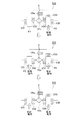
次に、一のレジスト液供給系500にフィルタ装置52aを取付けた後、ウエハWに当該レジスト液供給系500により処理を行う前に、前記脱気液供給処理を行う工程について、レジスト液供給系500の概略図である図6ないし図11を参照して説明する。図6〜図11においては、ポンプP1、P2の動作、各弁の開閉及びレジスト液供給系500内の圧力の変化によってレジスト液Lが流れる、または流れ得る管路については、このような流れが起こらない管路よりも太く示している。また、図の煩雑化を避けるためにレジスト容器60に接続される気体供給管路8aなど、図3で示した一部の構成については省略している。また、図12〜図16は、前記前記脱気液供給処理を行う各工程におけるポンプP1、P2及びフィルタ装置52aの状態を示した説明図であり、これらの図12〜図16も適宜参照する。
Next, a process for performing the degassing liquid supply process after attaching the
バッファタンク61のドレイン管路61cの切換弁V6aを開放した状態で、N2ガス供給源62(図3参照)からのN2ガスによりレジスト容器60内を加圧し、レジスト液Lがレジスト容器60からバッファタンク61内に供給される。然る後、切換弁V6aが閉鎖されて、バッファタンク61内についても加圧され、レジスト液Lが供給ポンプP1に供給される。その後、前記N2ガスの供給が停止され、供給ポンプP1の動作により、バッファタンク61のレジスト液Lがフィルタ装置52a及び吐出ポンプP2に供給される。吐出ポンプP2の動作により、当該ポンプP2からノズル7aに至るまでの処理液供給管路51b及び帰還用管路55にレジスト液Lが供給され、レジスト液供給系500は待機状態とされる(図6、ステップS1)。
With the switching valve V6a of the
前記待機状態において、ポンプP1、P2の各開閉弁V31〜V35、供給制御弁57、フィルタ装置52aのベント用管路51cの切換弁V4a、バッファタンク61のドレイン管路61cの切換弁V6aは閉鎖されている。また、この待機状態においては、供給ポンプP1のポンプ室103は、図4上段に示したように拡張した状態であり、吐出ポンプP2のポンプ室103は、図4下段に示したように収縮した状態となっている。
In the standby state, the on-off valves V31 to V35 of the pumps P1 and P2, the
続いて、図7に示すように弁V4a、供給ポンプP1の二次側(吐出側)の弁V32が開放されると共に供給ポンプP1がレジスト液Lの吐出動作を行い、そのポンプ室103が若干収縮され、フィルタ装置52aがベントされる(ステップS2)。然る後、吐出動作が停止し、前記弁V32が閉じてベントが終了する。図12は、このベント終了時のポンプP1、P2及びフィルタ装置52aを示している。
Subsequently, as shown in FIG. 7, the valve V4a and the valve V32 on the secondary side (discharge side) of the supply pump P1 are opened, and the supply pump P1 performs the discharge operation of the resist solution L. The
続いて、図8に示すように供給ポンプP1の動作が停止した状態で、吐出ポンプP2の一次側(吸入側)の弁V34及び供給ポンプP1の二次側の弁V32が開かれると共に、当該吐出ポンプP2が吸液動作を開始する。つまり、供給ポンプP1のポンプ室103の容積が一定の状態で、吐出ポンプP2のポンプ室103が拡張される。このとき、図8中に点線で囲んだ領域、即ちポンプP1、P2のポンプ室103、フィルタ装置52a内、処理液供給管路51bにおけるポンプP1からP2に至る領域及び帰還用管路55は、密閉空間を形成しており、前記吐出ポンプP2のポンプ室103の拡張により、この密閉空間内が減圧される(ステップS3)。そのように減圧されることで、図13に示すように、この密閉空間内のレジスト液Lに溶存していた気泡L1が析出し、前記レジスト液Lの脱気が進行する。
Subsequently, with the operation of the supply pump P1 stopped as shown in FIG. 8, the primary side (suction side) valve V34 of the discharge pump P2 and the secondary side valve V32 of the supply pump P1 are opened. The discharge pump P2 starts the liquid suction operation. That is, the
続いて、図9に示すように吐出ポンプP2の吸液動作が続けられたまま、供給ポンプP1の吐出動作が行われ、当該供給ポンプP1のレジスト液Lは、フィルタ装置52aを通過して濾過され、吐出ポンプP2に送液される(ステップS4)。供給ポンプP1のポンプ室103が収縮することで、前記密閉空間の減圧状態は解除される。ここで、フィルタ52fの上流側において、脱気されたレジスト液Lがフィルタ52fに供給されることで、既述したようにフィルタ52fに含まれる気泡L1がこのレジスト液Lに溶解し、このレジスト液Lがフィルタ52fの孔を通過して、二次側(吐出ポンプP2側)へ供給される。前記フィルタ52fに付着しているパーティクルも前記レジスト液Lによって、フィルタ52fの二次側へ押し流される。図14に示すように、フィルタ52fは、その一次側からレジスト液Lと共に流れてきた前記気泡L1を通過させず、当該気泡L1は、フィルタ52fの一次側のレジスト液流路52pに貯留され、レジスト液流路52pの上方に気層を形成する。
Subsequently, as shown in FIG. 9, the discharge operation of the supply pump P1 is performed while the liquid suction operation of the discharge pump P2 is continued, and the resist solution L of the supply pump P1 is filtered through the
例えば、供給ポンプP1がレジスト液Lを吐出し切ると共に、吐出ポンプP2がレジスト液Lを吸液し切ると、供給ポンプP1の二次側の弁V32、吐出ポンプP2の一次側のV34が閉じられる。続いて、吐出ポンプP2の帰還用管路55に接続する弁V33及び供給ポンプP1の一次側の弁V31が開放され、図10に示すように、吐出ポンプP2の吐出動作が開始される。これによって吐出ポンプP2内のレジスト液Lが、前記気泡L1やフィルタ52fから流出した前記パーティクルと共に、帰還用管路55を介してフィルタ52fの上流側、具体的には、供給ポンプP1のポンプ室103及び供給ポンプP1の上流側の処理液供給管路51bへとパージされる(ステップS5)。
For example, when the supply pump P1 completely discharges the resist solution L and the discharge pump P2 completely absorbs the resist solution L, the secondary side valve V32 of the supply pump P1 and the primary side V34 of the discharge pump P2 are closed. . Subsequently, the valve V33 connected to the
例えば吐出ポンプP2がレジスト液Lを吐出し切ると、前記弁V33が閉じられ、図11に示すように供給ポンプP1の吸液動作が開始され、供給ポンプP1内に一次側から供給されたレジスト液Lが再充填される(ステップS6)。供給ポンプP1がレジスト液Lを吸液し切ると、ポンプP1の一次側の弁V31が閉鎖され、レジスト液供給系500はステップS1の待機状態となる。
For example, when the discharge pump P2 completely discharges the resist solution L, the valve V33 is closed, and the suction operation of the supply pump P1 is started as shown in FIG. 11, and the resist solution supplied from the primary side into the supply pump P1. L is refilled (step S6). When the supply pump P1 has completely absorbed the resist solution L, the valve V31 on the primary side of the pump P1 is closed, and the resist
このステップS1以降、同様にステップS2〜S6が行われる。2回目のステップS2について説明すると、既述の1回目のステップS3、S4において、減圧及び濾過を行ったことにより、図14で説明したようにフィルタ装置52aには気泡L1が蓄積して気層が形成されている。この気層については、当該2回目のステップS2が行われることで、ベント用管路51cを介してフィルタ装置52aから除去される(図16)。また、図15で説明したように1回目のステップS5で、パーティクルを含んだレジスト液Lが供給ポンプP1へ供給されており、この2回目のステップS2ではベントを行うにあたり、当該レジスト液Lがフィルタ装置52aに供給され、前記気層と共にベント用管路51cから除去されることになる。
After this step S1, steps S2 to S6 are similarly performed. The second step S2 will be described. As a result of the pressure reduction and filtration performed in the first steps S3 and S4, the bubbles L1 are accumulated in the
2回目のステップS3では1回目のステップS3と同様に、形成された閉鎖空間が減圧されて、レジスト液Lに気泡L1が析出する。そして2回目のステップS4では、1回目のステップS4と同様に濾過が行われる。この濾過時にて、既述のように気泡L1はフィルタ52fを通過できずに、フィルタ装置52aの流路内にて気層を形成して溜まる。この気層は、3回目のステップS2のベントでフィルタ装置52aから除去されることになる。また、この2回目のステップS4においては、前記2回目のステップS2で供給ポンプP1からフィルタ装置52aに移行しなかったレジスト液Lが、当該フィルタ装置52aに移行し、このレジスト液L中のパーティクルについては、フィルタ52fを通過できず、当該フィルタ52fにより捕集される。そして、この2回目のステップS4の濾過によっても、1回目のステップS4と同様に、脱気されたレジスト液Lにフィルタ52fの気泡L1が溶けて、フィルタ52fの孔内へのレジスト液Lの通流が進行する。
In the second step S3, as in the first step S3, the formed closed space is decompressed, and bubbles L1 are deposited in the resist solution L. In the second step S4, filtration is performed in the same manner as in the first step S4. At the time of this filtration, the bubbles L1 cannot pass through the
2回目のステップS5、S6が行われた後、さらにステップS1〜S6が行われる。このようにステップS1〜S6が繰り返され、フィルタ52fからの異物の除去が進行する。ステップS1〜S6が予め設定した回数繰り返されると、この脱気液供給処理が終了し、レジスト液供給系500は例えば後述するステップS11の待機状態に維持される。なお、ステップS2のベントは毎回行われることに限られない。ステップS3が行われるたびに、当該ステップS3において析出する気泡L1の量は少なくなる。そこで処理速度の向上を図るため、この脱気液供給処理が進行するにつれて、前記ベントを行う回数を少なくしてもよい。具体的には例えばステップS1、S3〜S6を繰り返し20回、つまり20サイクル行うとすると、1〜10回目のサイクルでは毎回ステップS2を実行し、11〜20回目のサイクルでは、偶数回のサイクルのみステップS2を行うようにしてもよい。
After steps S5 and S6 are performed for the second time, steps S1 to S6 are further performed. In this way, steps S1 to S6 are repeated, and the removal of foreign matter from the
続いて、脱気液供給処理後に行われるウエハWへのレジスト液Lの吐出処理について図17〜図21を参照しながら説明する。図17〜図21においても、図6〜図11と同様に、レジスト液Lの流通が起こる管路について、流通が起きない管路よりも太く示している。この吐出処理の説明では、ノズル7aに接続されるレジスト液供給系500で処理するように設定されたウエハWがレジスト液供給装置5に搬送された場合における、当該レジスト液供給系500の動作を例に挙げて説明する。
Next, the discharge process of the resist liquid L onto the wafer W performed after the degassing liquid supply process will be described with reference to FIGS. Also in FIGS. 17 to 21, similar to FIGS. 6 to 11, the pipeline in which the resist solution L flows is shown thicker than the pipeline in which the flow does not occur. In the description of the discharge process, the operation of the resist
図17は、前記脱気液供給処理後、待機状態に置かれた前記レジスト液供給系500を示している(ステップS11)。この吐出処理時の待機状態S11は、前記脱気液供給処理時の待機状態S1と、各開閉弁の開閉状態については同様である。既述の待機状態S1では、吐出ポンプP2はレジスト液を吐出し切った状態として説明したが、この待機状態S11では、続くステップS12でウエハWにレジスト液を吐出できるように、例えばS1の待機状態からポンプP1、P2の動作及び各弁の開閉により、供給ポンプP1のレジスト液Lが所定量、フィルタ装置52aを介して吐出ポンプP2に移された状態となっている。
FIG. 17 shows the resist
前記ウエハWがレジスト液供給装置5に搬入されると、図18に示すようにレジスト液供給系500の吐出ポンプP2が吐出動作を開始すると共に、当該吐出ポンプP2の二次側の弁V35及び供給制御弁57が開かれ、レジスト液LがウエハWに吐出される。ウエハWへのレジスト液Lの吐出量は例えば1mLに設定される。1枚のウエハWに吐出が終了すると、弁V35及び供給制御弁57が閉鎖される。この処理済みのウエハWと同ロットのウエハWが1枚ずつ連続してレジスト液供給装置5に搬送され、その都度、弁V35及び供給制御弁57が開閉されると共に吐出ポンプP2の吐出動作が行われ、これらウエハWにレジスト液の吐出が行われる。これらのウエハWへのレジスト液の吐出に並行して、供給ポンプP1の一次側の弁V31が開かれて当該供給ポンプP1が吸液動作を行い、当該供給ポンプP1にレジスト容器60からレジスト液が供給される(ステップS12)。
When the wafer W is loaded into the resist
前記ロットのウエハWを全て処理し終わるか、吐出ポンプP2がレジスト液Lを吐出し切ると、既述の脱気液供給処理のステップS4と同様に、各弁の開閉及びポンプP1、P2の動作が行われ、供給ポンプP1のレジスト液Lがフィルタ装置52aにより濾過されて吐出ポンプP2に供給される(図19、ステップS13)。前記ロットのウエハWを全て処理し終わり、当該ステップS13が行われた後に、前記脱気液供給処理のステップS2と同様に各弁の開閉及び供給ポンプP1の吐出動作が行われ、フィルタ装置52aのベントが行われる(図20、ステップS14)。
When all the wafers W in the lot have been processed or the discharge pump P2 has completely discharged the resist solution L, the opening and closing of the valves and the operation of the pumps P1 and P2 are performed as in step S4 of the deaeration liquid supply processing described above. The resist solution L of the supply pump P1 is filtered by the
その後、脱気液供給処理のステップS5と同様に、各弁の開閉及び供給ポンプP1の吐出動作が行われ、吐出ポンプP2から供給ポンプP1へのレジスト液Lのパージが行われる(図21、ステップS15)。このパージは、ウエハWに吐出されるレジスト液に異物が混入することを、より確実に防ぐために行われる。ステップS15終了後、レジスト液供給系500はステップS11の待機状態とされる。然る後、このノズル7aのレジスト液供給系500で処理するように設定された後続のロットのウエハWがレジスト液供給装置5に搬入されたときには、同様にステップS12〜S15の処理が行われる。
Thereafter, similarly to step S5 of the deaeration liquid supply process, the opening and closing of each valve and the discharge operation of the supply pump P1 are performed, and the resist liquid L is purged from the discharge pump P2 to the supply pump P1 (FIG. 21, FIG. 21). Step S15). This purging is performed in order to more reliably prevent foreign matters from being mixed into the resist solution discharged onto the wafer W. After step S15 is completed, the resist
ところで、このレジスト液の吐出処理においても、前記ステップS14のベントはステップS11〜S13を行うたびに実行することに限られない。つまり、通常はステップS11〜S13の後にステップS15を行うように設定し、このサイクルを1回または複数回行ったら、次のサイクルではステップS13とステップS15との間に当該ステップS14を行うように設定してもよい。そのように処理を行うことで、処理速度の低下を抑えることができる。 By the way, also in this resist solution discharge process, the venting of step S14 is not limited to being performed every time steps S11 to S13 are performed. In other words, it is usually set to perform step S15 after steps S11 to S13, and when this cycle is performed once or a plurality of times, step S14 is performed between step S13 and step S15 in the next cycle. It may be set. By performing such processing, it is possible to suppress a decrease in processing speed.
続いて、循環濾過処理について、図22〜図25を参照しながら説明する。上記のステップS11(図17参照)の待機状態となっているレジスト液供給系500について、図22に示すように供給ポンプP1の一次側の弁V31が開かれると共に、当該供給ポンプP1の吸液動作が行われる(ステップS21)。その後、既述のステップS4、S13と同様に、供給ポンプP1のレジスト液Lがフィルタ装置52aで濾過されて、吐出ポンプP2へ供給される(図23、ステップS22)。
Next, the circulation filtration process will be described with reference to FIGS. With respect to the resist
然る後、ステップS2、S14と同様にフィルタ装置52aのベントが行われる(図24、ステップS23)。その後、既述のステップS5と同様に、吐出ポンプP2から供給ポンプP1へ、レジスト液Lのパージが行われる(図25、ステップS24)。各ステップS22〜S24においては、既述の脱気液供給処理及び吐出処理の対応する各ステップSと同様に、各弁の開閉及びポンプP1、P2の動作が制御される。前記ステップS24の後は、ステップS21〜S24が繰り返し行われる。例えばステップS21〜S24を一つのサイクルとすると、一のサイクル終了後、所定の間隔、例えば15分程度の間隔をおいて次のサイクルが行われる。
Thereafter, the
このようにステップS21〜S24が行われることで、発明が解決する課題の項目で述べた、フィルタ52fにおけるレジスト液の滞留が起きることを防ぐことができる。従って、当該フィルタ52fに滞留している気泡やゲルが、フィルタ52fとレジスト液Lとの界面でパーティクルとして成長・増加することを防ぐことができる。さらに、前記ステップS21〜S24が繰り返され、レジスト液Lが繰り返しフィルタ装置52aを通過するので、より確実にレジスト液L中の異物がフィルタ装置52aにより除去される。
By performing steps S21 to S24 as described above, it is possible to prevent the resist solution from staying in the
ところで前記ステップS24において、吐出ポンプP2からパージされるレジスト液Lの量(パージ量)は、前記吐出処理における1枚のウエハWへのレジスト液の吐出量と同じか、それよりも多くなるように吐出ポンプP2の動作が制御される。このようにパージ量を制御するのは、上記のパーティクルの増加を抑制する効果を確実に得るために、フィルタ52fを通流するレジスト液の量を比較的多くすることを目的とする。ところで、この循環濾過処理においても、前記ステップS23のベントは、ステップS21、S22を行うたびに実行することに限られず、ステップS21、S22、S24を複数回行ったら、当該ステップS22、S24を行う間に1回行うようにしてもよい。
Incidentally, in step S24, the amount (purge amount) of the resist solution L purged from the discharge pump P2 is equal to or larger than the amount of resist solution discharged to one wafer W in the discharge process. The operation of the discharge pump P2 is controlled. The purpose of controlling the purge amount in this way is to relatively increase the amount of the resist solution flowing through the
上記の循環濾過処理が行われるタイミングの一例について、図26のフローチャートを参照しながら説明する。コントローラ200は、一のレジスト液供給系500において、直近のウエハWにレジスト吐出を行ってから予め設定された時間が経過したか否か判定する。つまり直近の前記ステップS12(図18参照)において、最後に吐出ポンプP2にレジスト液Lを吐出させるために制御信号を送信してから、設定時間が経過したか否かを判定する(ステップS31)。設定時間が経過していないと判定された場合は、このステップS31の判定が繰り返し行われる。
An example of the timing at which the above circulation filtration process is performed will be described with reference to the flowchart of FIG. The
前記設定時間が経過したと判定された場合、このレジスト液供給系500において、循環濾過処理が開始される。つまりステップS21〜S24(図22〜図25)で説明した動作が行われる(ステップS32)。そして、この循環濾過処理実行中のレジスト液供給系500で処理を行うように設定されたウエハWが、レジスト液供給装置5に搬送されたか否かが判定される(ステップS33)。前記ウエハWが搬送されていないと判定された場合、このステップS33の判定が繰り返し行われる一方で、循環濾過処理が継続して行われる。例えばこの循環濾過処理で、ステップS24のパージ終了後(図24参照)、次のステップS21の供給ポンプP1への液充填(図22参照)を行うタイミングになっても、前記ウエハWがレジスト液供給装置5に搬送されていないと判定された場合は、当該ステップS21が行われる。つまりステップS21〜S24が繰り返し行われる。
When it is determined that the set time has elapsed, the circulation filtration process is started in the resist
前記ステップS33でウエハWがレジスト液供給装置5に搬送されたと判定された場合、この循環濾過処理を停止して、吐出処理に移行できる移行許可期間か否か判定される(ステップS34)。移行許可期間は例えば、前記ステップS24のパージが終了後、次のステップS21が開始されるまでの期間であり、当該期間であると判定されれば、循環濾過処理が終了される。そして、既述のステップS11〜S15(図17〜図21)に従って、搬送されたウエハWへのレジスト液Lの吐出処理が行われる(ステップS35)。
If it is determined in step S33 that the wafer W has been transferred to the resist
前記ステップS34にて例えば前記移行許可期間外と判定された場合、循環濾過処理が継続される一方で、当該ステップS34の判定が繰り返し実行される。循環濾過処理が進行して上記のステップS24のパージが終了すると、前記ステップS34で移行許可期間であると判定され、前記ステップS35のレジスト液の吐出処理が開始される。 For example, when it is determined in step S34 that it is outside the transition permission period, the circulation filtering process is continued, while the determination in step S34 is repeatedly executed. When the circulation filtration process proceeds and the purge in step S24 is completed, it is determined in step S34 that the transition is permitted, and the resist solution discharge process in step S35 is started.
前記移行許可期間としては上記の例に限られず、例えば一つのサイクルのステップS21からS24に至るまでの間において、一のステップから次のステップへ移行するまでの期間、つまり各ステップSの実行中以外の期間であってもよい。 The transition permission period is not limited to the above example. For example, during the period from step S21 to S24 of one cycle, the period from one step to the next step, that is, during the execution of each step S Other periods may be used.
ところでフィルタ装置52aの使用を続けると、フィルタ52fに気泡L1が蓄積される場合がある。この気泡L1を除去するために、上記のフローチャートのステップS31〜S35に沿って、循環濾過処理の代わりに上記の脱気液供給処理が行われるようにしてもよい。つまり脱気液供給処理は、フィルタ装置52aのレジスト液供給系500への取付け時に行うことに限られない。このように循環濾過処理の代わりに上記の脱気液供給処理を行う場合、前記レジスト液の吐出処理への移行許可期間としては、例えばステップS1(図6)の待機状態になっているときとする。
By the way, if the use of the
また、吐出処理後の設定時間経過後に循環濾過処理が行われる例について示したが、循環濾過処理を行うタイミングは、この例に限られない。例えば、脱気液供給処理が終了してから予め設定された時間が経過したか否かが判定されるステップが実施され、当該ステップで設定時間が経過したと判定された場合にも、図26のフローのステップS32以降のステップが実施され、循環濾過処理が行われるようにしてもよい。 Moreover, although the example in which the circulation filtration process is performed after a set time after the discharge process has been shown, the timing of performing the circulation filtration process is not limited to this example. For example, a step of determining whether or not a preset time has elapsed since the deaeration liquid supply process has been completed is performed, and even when it is determined that the set time has elapsed in this step, FIG. The steps after step S32 of the flow may be performed to perform the circulation filtration process.
このレジスト液供給装置5によれば、ポンプP1、P2とフィルタ装置52aと処理液供給管路51とにより構成される空間を弁により閉鎖して、密閉空間を形成し、吐出ポンプP2の吸液動作により当該密閉空間を減圧する。これによってレジスト液中に存在する微細な気泡を顕在化させて、当該レジスト液を脱気する。この脱気したレジスト液をフィルタ装置52aの一次側から二次側に通流させて、フィルタ52fに含まれる気泡を当該レジスト液に溶解させる。これによって、前記気泡を効率的に除去し、当該気泡がパーティクルとなってウエハWに吐出されるレジスト液に混入すること及び当該気泡によってフィルタ装置52aの異物の捕集性能が低下することを抑えることができる。また、レジスト容器60からフィルタ装置52aを介してノズルユニット70にレジスト液を流し続けるダミー吐出を行うようにして前記気泡を除去するよりも、レジスト液の無駄を抑えることができ、装置の運用コストを低下させることができる。
According to this resist
また、レジスト液供給装置5においては、既述のステップS1〜S6を繰り返し、それによって前記減圧によるレジスト液の脱気と、帰還用管路55と処理液供給管路51とからなる循環流路を介しての前記レジスト液のフィルタ装置52aへの通流と、が複数回繰り返し行われる。そのため、前記フィルタ52fにおける気泡の除去を、より確実に行うことができる。
Further, in the resist
また、レジスト液の吐出処理及び脱気液供給処理を行わないときに、前記循環濾過処理が行われる。この循環濾過処理によって既述のように、より確実にフィルタ装置52aの気泡を除去し、ウエハWに吐出されるレジスト液へパーティクルが混入することを抑えることができる。また、この処理によって当該気泡を除去するための前記ダミー吐出の量を、より確実に抑えることができる。
The circulation filtration process is performed when the resist solution discharge process and the degassed liquid supply process are not performed. As described above, this circulating filtration process can more reliably remove bubbles in the
前記循環濾過処理を行うタイミングとしては、上記の例に限られない。例えば、ウエハWがレジスト液供給装置5に搬送されると、この循環濾過処理が行われ、ステップS21〜S24が例えば1回行われた後に、ステップS11〜S15のレジスト液の吐出処理が行われるようにしてもよい。ただし、図26のフローで説明したように、ウエハWにレジスト液を吐出後、設定時間経過後に当該循環濾過処理を行う方が、レジスト液の吐出処理を開始するまでの時間のロスを少なくすることができ、スループットの向上を図ることができる。
The timing for performing the circulation filtration process is not limited to the above example. For example, when the wafer W is transferred to the resist
また、一のレジスト液供給系500で循環濾過処理または脱気液供給処理を行うことに並行して、他のレジスト液供給系500ではウエハWへのレジスト液の吐出処理を行うことができる。そのように各レジスト液供給系500が制御されることで、循環濾過処理及び脱気液供給処理により、レジスト液の吐出処理の開始タイミングが遅延することを防ぎ、レジスト液供給装置5の生産性が低下することを防ぐことができる。
Further, in parallel with performing the circulating filtration process or the degassed liquid supply process in one resist
また、レジスト液供給装置5においては、フィルタ装置52aの一次側、二次側に夫々ポンプP1、P2を配置しているので、フィルタ装置52aの内圧の調整が容易である。より具体的に説明すると、脱気液供給処理時には既述のように減圧空間を形成することができ、レジスト液の吐出処理において濾過を行う際には、フィルタ装置52aの一次側で供給ポンプP1が吐出動作を行いながら、フィルタ装置52aの二次側で吐出ポンプP2が吸液動作を行うので、フィルタ装置52aの内圧が低下することにより当該フィルタ装置52a内でレジスト液が発泡することを防ぐことができる。つまり、ウエハWへのレジスト液吐出時に、当該レジスト液に気泡が混入することを抑えることができる。
Further, in the resist
<第2実施形態>
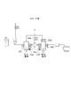
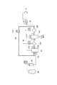
図27に基づいて、第2実施形態であるレジスト液供給装置511を説明する。なお、第2実施形態及び以降の各実施形態において、第1実施形態と同一の構成については、同一部分に同一符号を付して説明を省略する。レジスト液供給装置511には、レジスト液供給系500の代わりにレジスト液供給系501が設けられる。レジスト液供給系501は、フィルタ装置52aの二次側の処理液供給管路51に介設されるトラップタンク53と、トラップタンク53の二次側の処理液供給管路51に介設されるポンプPと、ポンプPの吐出側とフィルタ装置52aの吸入側とを接続する帰還用管路55と、を具備する。
Second Embodiment
Based on FIG. 27, a resist
前記帰還用管路55は、トラップタンク53とポンプPを接続する第1の帰還用管路55aと、トラップタンク53とフィルタ装置52aの一次側の第2の処理液供給管路51bとを接続する第2の帰還用管路55bと、からなる。また、第2の帰還用管路55bには切換弁56が介設されている。処理液供給管路51において、第2の帰還用管路55bの接続部とフィルタ装置52aとの間には切換弁58が介設されている。
The
トラップ貯液部であるトラップタンク53は、バッファタンク61と同様にレジスト液を貯留し、その内部の上方にはトラップした気体が蓄積される。トラップタンク53の上部には、タンク内の前記気体を除去するためのベント用管路51dが設けられ、当該ベント用管路51dには切換弁V5aが介設されている。また、図中8bは、電空レギュレータRを介してガス供給源62とバッファタンク61とを接続する第2の気体供給管路であり、当該気体供給管路8bには切換弁V3が介設されている。図中61dは、バッファタンク61内が過剰に加圧されることを防ぐための管路であり、弁が介設されるが後述の各ステップでは常時開かれた状態とされるので、当該弁の図示は省略する。
The
ポンプPとしては、第2の処理液供給管路51b内の処理液を吸入、吐出するダイヤフラムポンプが用いられる。このポンプPは、可撓性部材であるダイヤフラム71にてポンプ部分に相当するポンプ室72と駆動部分に相当する作動室73に仕切られている。このポンプPの一次側には第2の処理液供給管路51b内の処理液を吸入するための吸入口が形成されており、このポンプPの一次側(吸入口側)には、電磁式の開閉弁V36が設けられている。
As the pump P, a diaphragm pump that sucks and discharges the processing liquid in the second processing
便宜上、図ではポンプPの吐出口は2箇所に形成されているように示しているが実際には吐出口は1箇所であり、この吐出口に接続される管路が分岐して、処理液供給管路51b及び帰還用管路55を構成している。そして、そのように分岐した管路には、分岐点付近に電磁式の開閉弁V37、V38が各々設けられ、ポンプPから各管路51b、55へのレジスト液の供給が制御される。作動室73にはコントローラ200からの信号に基づいて作動室73内の気体の減圧及び加圧を制御する電空レギュレータを備える駆動手段74が接続されている。このポンプPは、フィルタ装置52aの一次側から二次側へレジスト液を通過させる送液用のポンプと、減圧空間を形成するための減圧用のポンプとを兼用するものである。
For convenience, in the figure, the discharge port of the pump P is shown to be formed at two locations, but in reality there is only one discharge port, and the pipe connected to this discharge port branches off, and the treatment liquid
このレジスト液供給装置511の各レジスト液供給系501についても、第1実施形態と同様に脱気液供給処理、レジスト液の吐出処理及び循環濾過処理が行われる。前記脱気液供給処理について、既述の図27及び図28〜図34に基づいて説明する。図27は液処理供給系501の待機状態を示しており、この待機状態では図に示す各弁は閉鎖されている。レジスト容器60からノズルユニット70に至るまでレジスト液Lが供給されており、ポンプPはレジスト液Lを吸液した状態となっている(ステップS41)。
The resist
前記待機状態から、ポンプPの二次側の弁V38、トラップタンク53のベント用管路51dの弁V5aが開かれると共にポンプPの吐出動作が行われる(図28)。これによりトラップタンク53にトラップされた気体が、ベント用管路51dから除去される(ステップS42)。
From the standby state, the valve V38 on the secondary side of the pump P and the valve V5a of the
続いて、前記弁V5aが閉じられ、ポンプPの一次側の弁V36が開かれ、さらにポンプPの吸液動作が行われる。このとき、帰還用管路55bにおいてトラップタンク53から弁56に至る領域、帰還用管路55a、トラップタンク53、フィルタ装置52a及びトラップタンク53により密閉空間が構成されている。図29では、この密閉空間が形成されている範囲を点線で囲って示している。ポンプPの吸液動作により当該密閉空間が拡張され、第1実施形態で説明したように、密閉空間中のレジスト液Lの気泡が顕在化する(ステップS43)。
Subsequently, the valve V5a is closed, the valve V36 on the primary side of the pump P is opened, and the liquid suction operation of the pump P is further performed. At this time, the area from the
然る後、ポンプPの吸液動作が続けられたままフィルタ装置52aの一次側の弁58が開放され、バッファタンク61から減圧雰囲気にレジスト液Lが引き込まれるように流れ、前記減圧状態が解除される。フィルタ装置52a内のフィルタ52fのパーティクルが前記レジスト液によりポンプPへ押し流され、フィルタ52fから除去される。前記密閉空間においてトラップタンク53の一次側で発生した気泡は、このトラップタンク53に捕集される。トラップタンク53の二次側で発生した気泡は、前記レジスト液と共にポンプPに流入する(ステップS44)。
Thereafter, the
その後、上記の図28に示したステップS42が行われ、ポンプPの気泡を含んだレジスト液はトラップタンク53に供給され、当該気泡はベント用管路51dよりトラップタンク53から除去される。また、前記レジスト液に含まれるパーティクルも、このトラップタンク53のベントにより、当該レジスト液と共に除去される。この2回目のステップS42の後は、ステップS43、S44が行われ、然る後、ステップS42〜S44がさらに行われる。このようにステップS42〜S44が繰り返し行われる。所定の回数、ステップS42〜S44が繰り返されると、ステップS44の状態からフィルタ装置52aの一次側の弁58、ポンプPの一次側のV36が閉じられ、レジスト液供給系501がステップS41の待機状態となる。
Thereafter, step S42 shown in FIG. 28 is performed, and the resist solution containing bubbles of the pump P is supplied to the
続いて図31に示すように、ポンプPの帰還用管路に接続される弁V38、帰還用管路55における弁56が開かれると共にポンプPの吐出動作が行われ、帰還用管路55を介してポンプPのレジスト液Lがバッファタンク61に戻される(ステップS45)。このバッファタンク61へ戻されるレジスト液Lは、上記のステップS42〜S44が繰り返されることで脱気された液である。そして、前記弁V38、56が閉鎖され、図32に示すようにポンプPの一次側の弁V36が開放されると共にポンプPの吸液動作が行われる。これによって、ステップS43と同様に減圧空間が形成され、当該空間内にてレジスト液の脱気が更に進行する(ステップS46)。
Subsequently, as shown in FIG. 31, the valve V38 connected to the return line of the pump P and the
そして、図33に示すように前記吸液動作が行われた状態でフィルタ装置52aの一次側の弁58が開かれ、ステップS44と同様にバッファタンク61からフィルタ装置52aを介してポンプPにレジスト液が流れ込む(ステップS47)。
フィルタ装置52aに供給されるレジスト液Lは、上記のようにステップS41〜S44で脱気された液であり、フィルタ52fの気泡を効率よく溶解させることができる。
Then, as shown in FIG. 33, the
The resist liquid L supplied to the
その後は、ステップS45〜S47のステップが繰り返し行われる。前記ステップS46において脱気されたレジスト液Lは、次に行われるステップS45でバッファタンク61に戻され、ステップS47でフィルタ装置52aに通流され、このレジスト液L中にフィルタ装置52aの気泡が溶解される。ステップS45〜S47が所定の回数、繰り返し行われると、液処理供給系501はステップS41(図27)の待機状態に戻る。
Thereafter, steps S45 to S47 are repeatedly performed. The resist solution L deaerated in step S46 is returned to the
その後、フィルタ装置52aの一次側の弁58、フィルタ装置52aのベント用管路51cの弁V4aが開かれる。さらに気体供給管路8bの弁V3が開かれ、ガス供給源62から供給されるガスによりバッファタンク61内が加圧され、当該タンク61内のレジスト液Lがフィルタ装置52aに供給されてフィルタ装置52aがベントされる(図34 ステップS48)。然る後、前記弁58、V4a、V3が閉鎖され、レジスト液供給系501は前記待機状態に戻る。
Thereafter, the
続いて、レジスト液供給系501によるレジスト液の吐出処理について説明すると、図27の待機状態のレジスト液供給系501からポンプPの二次側の弁V37、57が開かれ、ポンプPが吐出動作を行い、ノズルユニット70からレジスト液が吐出される。ポンプPがレジスト液を吐出し切ると、前記弁V37、57が閉じた状態で、ポンプPの一次側の弁V36、フィルタ装置52aの弁58が開かれ、ポンプPが吸液動作を行い、バッファタンク61からレジスト液が、フィルタ装置52a、トラップタンク53を介してポンプPに供給される。
Next, the resist solution discharge process by the resist
続いて、レジスト液供給系501における循環濾過処理について説明する。各弁が閉鎖された前記待機状態から、上記の脱気液供給処理のステップS45(図31)と同様に弁の開閉が行われると共にポンプPの吐出動作が行われ、帰還用管路55を介してポンプPのレジスト液Lがバッファタンク61に戻される(図35 ステップS51)。このステップS51におけるポンプPの吐出量は、次のステップS52で比較的多くの量のレジスト液を濾過するために、吐出処理時の1枚のウエハWに対する吐出量と同じか、それよりも大きくなるように設定される。続いて、帰還用管路55の弁56が閉じられ、フィルタ装置52aの一次側の弁58、ポンプPの一次側の弁V36が開かれる。このように弁の開閉が制御されると共に、ポンプPの吸液動作が行われ、バッファタンク61のレジスト液がフィルタ装置52aで濾過されて、トラップタンク53を通過して、ポンプPに戻される(図36 ステップS52)。
Next, the circulation filtration process in the resist
このステップS51、S52が繰り返し行われる。このステップS51、S52を1サイクルとすると、例えば連続して行われる複数回のサイクルのうちの1回のサイクルにおいては、ステップS52の代わりにトラップタンク53をベントするステップS53が行われる。このステップS53では、脱気液供給処理のステップS42と同様に各弁の開閉が制御されると共に、ポンプPの吐出動作が行われる(図37)。それによって、ポンプPのレジスト液Lがトラップタンク53を介してベント用管路51dへ流れ、トラップタンク53の気層が除去される。
Steps S51 and S52 are repeated. Assuming that steps S51 and S52 are one cycle, for example, in one cycle among a plurality of consecutive cycles, step S53 for venting the
この第2実施形態のレジスト液供給装置511においても、第1実施形態のレジスト液供給装置5と同様に、脱気液供給処理によりフィルタ装置52aにおける気泡の除去を効率よく行うことができる。また、循環濾過処理によりフィルタ装置52aにおけるパーティクルの成長を抑えることができる。
Also in the resist
<第3実施形態>
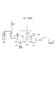
図38には、第3実施形態に係るレジスト液供給装置512を示している。当該レジスト液供給装置512は、第2実施形態で説明したレジスト液供給系501に代わりレジスト液供給系502を備えている。当該レジスト液供給系502における、レジスト液供給系501との差異点は、帰還用管路55が、55a、55bに分かれていないことである。帰還用管路55の一端は、弁V38を介してポンプPに接続され、他端は処理液供給管路51bにおいてバッファタンク61と弁58との間に接続されている。この帰還用管路55の構成を除き、レジスト液供給系502はレジスト液供給系501と同様に構成されている。
<Third Embodiment>
FIG. 38 shows a resist
第3実施形態のレジスト液供給系502においても、脱気液供給処理、ウエハWへのレジスト液の吐出処理及び循環濾過処理が行われる。各弁の開閉及びポンプPの動作は、レジスト液供給系501と同様に制御されて、第2実施形態で説明した各ステップSが実施される。ただし、ステップS51(図35)などにおいて、ポンプPのレジスト液をバッファタンク61に戻すにあたり、レジスト液供給系502では帰還用管路55に弁56が設けられていないため、当該弁56の開放は行われない。この第3実施形態においても、第2実施形態と同様の効果が得られる。
Also in the resist
<第4実施形態>
レジスト液の吐出処理に用いられるポンプP、P1を使用して、レジスト液を脱気することには限られない。図39に示すレジスト液供給装置513のレジスト液供給系503は、レジスト液供給系502と略同様に構成される。差異点としては、処理液供給管路51bにおいてバッファタンク61と帰還用管路55に対する接続点との間に、下流側に向かって、脱気機構80、前記切換弁58がこの順に介設される。
<Fourth embodiment>
It is not limited to degassing the resist solution using the pumps P and P1 used for the resist solution discharge process. The resist
前記脱気機構80は、図40(a)に示すように、容器81及び半透膜チューブ82を有しており、レジスト液L中に存在する気体を除去するように構成されている。また、容器81は、処理液供給管路51に接続する流入用ポート83及び流出用ポート84を有している。また、容器81は、レジスト液L中に存在する気体を外部に排出するための排出管86が接続する排気用ポート85を有している。なお、排出管86は図示しない排気ポンプもしくは排気エジェクターに接続されている。
As shown in FIG. 40A, the
一方、半透膜チューブ82は容器81内に配置され、かつ両ポート83,84に接続されている。そして、全体が例えば四弗化エチレン系あるいはポリオレフィン系の中空糸膜によって形成されている。そのため、ポンプPの駆動時に半透膜チューブ82内にレジスト液Lを流入させ、容器81内の半透膜チューブ82周辺の空気を図示しない排気ポンプを駆動させて排気することで半透膜チューブ82周辺の空気が減圧される。レジスト液L中の気体は、上記排気ポンプの駆動により半透膜チューブ82の外側へと排出され、排出管86を介して脱気機構80の外部に排出される。
On the other hand, the
このような脱気機構80を設けることで、この脱気機構80の下流側に脱気したレジスト液Lを供給することができる。ポンプPにより、そのように脱気したレジスト液を吸液して、処理液供給管路51及び帰還用管路55からなる環状路に導入し、当該環状路をポンプPから吐出される前記レジスト液が循環できるように各弁の開閉を制御する。そしてポンプPの吐出動作、吸液動作を複数回繰り返し行い、この環状路内で脱気したレジスト液を複数回繰り返し循環させる(図41)。つまり、第2実施形態と同様に、ポンプPの吐出動作によりポンプPからバッファタンク61へレジスト液Lを戻し、次いでこの戻したレジスト液LをポンプPの吸液動作によりポンプPへと引き込む。この動作を繰り返す。図41ではこの吐出動作及び吸液動作により、レジスト液が流れる管路を太く表示している。
By providing such a
前記環状路にはフィルタ装置52aが介設されるので、このフィルタ装置52aの一次側から二次側へ、脱気されたレジスト液が繰り返し供給される。それによって、既述の各実施形態の脱気液供給処理と同様に、レジスト液にフィルタ装置52aの気泡を溶解させ、当該気泡をフィルタ装置52aから効率的に除去することができる。
Since the
脱気機構80を設ける場所としては、図39の例では環状路の外側としたが、図42に示すように当該環状路に介設してもよい。図42の装置514のレジスト液供給系504では、フィルタ装置52aの一次側と、処理液供給管路51bにおける帰還用管路55に対する接続点との間に脱気機構80を設けている。そして、図41に示した例と同様に、前記環状路にてレジスト液の循環を行う。
The place where the
ところで、ポンプの動作によりレジスト液の脱気を行うために、第1実施形態においては、ポンプP1、P2及びフィルタ装置52aに減圧空間を形成している。第2、第3実施形態においてはフィルタ装置52a、トラップタンク53及びポンプPに減圧空間を形成している。減圧空間を形成する領域としては、これらの例に限られない。
By the way, in order to deaerate the resist solution by the operation of the pump, in the first embodiment, reduced pressure spaces are formed in the pumps P1 and P2 and the
図43のレジスト液供給装置515は、第3実施形態の変形例である。装置515のレジスト液供給系505は、第3実施形態のレジスト液供給系502と異なり、フィルタ装置52aとトラップタンク53との間の管路に切換弁81が介設されている。レジスト液を脱気する際にはポンプPの一次側の弁V36が開かれ、且つポンプPの二次側の弁V37、V38、弁81、トラップタンク53の弁V5a、フィルタ装置52aの弁V4aが閉じられる。それによってポンプP、トラップタンク53及び処理液供給管路51の当該ポンプPから弁81に至る領域が密閉空間となり、ポンプPが吸引動作を行うことで、当該密閉空間が減圧される。その後は、他の実施形態と同様に、密閉空間にて脱気されたレジスト液を、帰還用管路55を介してフィルタ装置52aの一次側から二次側へと通流させ、フィルタ装置52aの気泡を除去する。
A resist
その他に、ポンプP内のみを密閉空間としてレジスト液の脱気を行ってもよい。例えば前記レジスト液供給系505で、ポンプPが内部のレジスト液を吐出し切っていない状態で、弁V36、V37、V38を閉鎖し、ポンプPの吸液動作を行う。それによって、ポンプP内を減圧空間として、レジスト液を脱気することができる。ただし、減圧空間は広く構成するほど1回のポンプの動作で脱気できるレジスト液の量が多くなり、それによって短い時間でより多くの脱気されたレジスト液をフィルタ装置52aに供給し、速やかに気泡の除去を行うことができる。従って、上記の各実施形態のようにポンプPの他に、フィルタ装置52aやトラップタンク53についても減圧空間にすることができるようにレジスト液供給系を構成することが好ましい。
In addition, the resist solution may be degassed by using only the inside of the pump P as a sealed space. For example, in the resist
ところで、既述の各実施形態の脱気液供給処理では、処理液供給管路51と別個に設けられた帰還用管路55を用いて、フィルタ装置52aの二次側の脱気されたレジスト液をフィルタ装置52aの一次側に戻し、当該一次側からフィルタ装置52aの二次側へと通流しているが、そのように帰還用管路55を用いて前記レジスト液をフィルタ装置52aの一次側に戻すことに限られない。
By the way, in the deaerated liquid supply process of each of the above-described embodiments, the degassed resist on the secondary side of the
図44は、第1実施形態のレジスト液供給系500のポンプP1、P2及びフィルタ装置52aを示している。吐出ポンプP2にレジスト液が貯留された状態で、吐出ポンプP2の弁V33〜V35を閉鎖し、当該吐出ポンプP2内を密閉空間として吐出ポンプP2の吸液動作を行う(図44上段)。それによって、吐出ポンプP2内のレジスト液を脱気する。続いて、弁V34と、供給ポンプの弁V32を開く。そして、供給ポンプP1の吸液動作を行うと共に吐出ポンプP2の吐出動作を行い、脱気されたレジスト液を吐出ポンプP2からフィルタ装置52aを介して供給ポンプP1に通流させる(図44中段)。然る後、供給ポンプP1の吐出動作を行うと共に、吐出ポンプP2の吸液動作を行い、フィルタ装置52aの一次側から二次側へ、脱気されたレジスト液を通流させる。ただし、この通流方法によれば、フィルタ装置52aの二次側から一次側へレジスト液を流すことになるので、フィルタ装置52aからのパーティクルの流出を防ぐ観点から、既述のように帰還用管路55を用いることが好ましい。
FIG. 44 shows the pumps P1 and P2 and the
レジスト液供給系の構成については、上記の各例には限られない。例えば図3の第1実施形態において、レジスト容器60と供給ポンプP1との間にトラップタンク53を設けてもよい。当該トラップタンク53は、各ポンプP1、P2とフィルタ装置52aとの間に設けてもよいし、ポンプP2と供給制御弁57との間に設けてもよい。また、図27の第2実施形態において、図に示す位置にトラップタンク53が無く、ポンプPから直接フィルタ装置52aの一次側にレジスト液が供給される構成とされてもよいし、ポンプPと供給制御弁57との間に、さらにトラップタンク53を設けてもよい。このようにトラップタンク53は、各レジスト液供給系において任意の場所に配置することができる。また、図27においては、ポンプPの上流側にフィルタ装置52aを配置しているが、ポンプPの下流側にフィルタ装置52aを配置してもよい。
The configuration of the resist solution supply system is not limited to the above examples. For example, in the first embodiment of FIG. 3, a
その他にレジスト液を脱気する手法としては、例えば第1実施形態(図3参照)において、供給ポンプP1及びバッファタンク61に密閉空間を形成するために、弁V31を開放し、弁V32、V33、V6a、V2を閉じた状態とする。そして、供給ポンプP1の吸液動作を行い、前記密閉空間を減圧し、レジスト液を脱気する。つまり、第1実施形態において、ポンプP1、P2のうちのいずれのポンプを用いてレジスト液の脱気を行ってもよい。また、第1実施形態では、密閉空間を形成するにあたり吐出ポンプP2付近の弁V35を使用しているが、この弁V35を設けず、供給制御弁57を用いて密閉空間を形成してもよい。ただし、ポンプP2から供給制御弁57に至るまでの管路にて減圧により気泡が発生し、この気泡がウエハWに供給されてしまうことを防ぐために、より吐出ポンプP2に近い弁、つまり前記弁V35を用いて密閉空間を形成することが好ましい。
As another method for degassing the resist solution, for example, in the first embodiment (see FIG. 3), in order to form a sealed space in the supply pump P1 and the
なお、上記実施形態では、この発明に係る処理液供給装置をレジスト塗布処理装置に適用した場合について説明したが、レジスト液以外の処理液例えば現像液等の供給装置や洗浄処理の供給装置にも適用可能である。 In the above-described embodiment, the case where the processing liquid supply apparatus according to the present invention is applied to the resist coating processing apparatus has been described, but the processing liquid other than the resist liquid, for example, a supply apparatus for a developing solution or the supply apparatus for a cleaning process is also used. Applicable.
<第5実施形態>
第5実施形態は、図45に示すように、吐出ポンプP2の二次側に、既述のフィルタ装置52aとは別に更に他のフィルタ装置200を設けた例を示している。このフィルタ200と供給制御弁57との間における処理液供給管路51cには、帰還用管路201の一端側が接続されており、この帰還用管路201の他端側は、弁V51を介して、バッファタンク61と供給ポンプP1との間における処理液供給管路51bに接続されている。尚、図45中202はフィルタ装置200から気泡を排出するためのベント管、V52はこのベント管202に設けられた弁である。
<Fifth Embodiment>
As shown in FIG. 45, the fifth embodiment shows an example in which another
図45は、第5実施形態において吐出ノズル7aからレジスト液Lを吐出すると共に、供給ポンプP1にレジスト液Lをバッファタンク61から補充する様子を示している。この時、弁V51、V52は、各々閉じられている。なお、レジスト液Lの吐出動作に続いて行われるフィルタ装置52aへのレジスト液Lの通液動作や、各動作における弁V31〜V34及び供給制御弁57の開閉の説明については、既述の第1実施形態と重複するため省略する。ただし、この例では吐出ポンプP2の弁V35が設けられておらず、弁V35の代わりに供給制御弁57により密閉空間が形成される。
FIG. 45 shows how the resist liquid L is discharged from the
そして、レジスト液Lを供給ポンプP1の一次側に戻す時には、図46に示すように、帰還用管路201の弁V51を開放すると共に、他の弁V31〜V33及び供給制御弁57を閉鎖する。この状態において吐出ポンプP2の吐出動作を行い、当該吐出ポンプP1内のレジスト液Lは、フィルタ装置200を通過して、帰還用管路201を経由してバッファタンク61の二次側に到達する。
When returning the resist solution L to the primary side of the supply pump P1, as shown in FIG. 46, the valve V51 of the
第5実施形態では、吐出ノズル7aにレジスト液Lを通流させる時、レジスト液Lがフィルタ200を通過するので、例えば吐出ポンプP2においてパーティクルが発生した場合であっても、このパーティクルを捕集して清浄なレジスト液Lをウエハに供給できる。また、吐出ポンプP2内のレジスト液Lを供給ポンプP1の一次側に戻す時も、レジスト液Lがフィルタ装置200を通過するので、同様に吐出ポンプP2にてパーティクルが発生しても、当該パーティクルを捕集できる。
In the fifth embodiment, when the resist solution L is allowed to flow through the
5 レジスト液供給装置
500 レジスト液供給系
P1 供給ポンプ
P2 吐出ポンプ
51 処理液供給管路
52a フィルタ装置
52f フィルタ
55 帰還用管路
5 Resist
Claims (29)
前記処理液供給源に供給路を介して接続され、前記処理液を被処理体に吐出する吐出部と、
前記供給路に設けられ、処理液中の異物を除去するためのフィルタ装置と、
前記供給路におけるフィルタ装置の一次側及び二次側に夫々設けられた供給ポンプ及び吐出ポンプと、
前記処理液供給源から供給された処理液を、前記供給ポンプ及び吐出ポンプの少なくとも一方を用いて減圧して脱気し、次いで脱気された処理液を前記供給ポンプ及び吐出ポンプを用いて前記フィルタ装置の一次側から当該フィルタ装置を介して二次側へ通過させるように制御信号を出力する制御部と、を備えたことを特徴とする処理液供給装置。 A processing liquid supply source for supplying a processing liquid for processing the object to be processed;
A discharge unit connected to the processing liquid supply source via a supply path, and discharging the processing liquid to a target object;
A filter device provided in the supply path for removing foreign matter in the processing liquid;
A supply pump and a discharge pump respectively provided on the primary side and the secondary side of the filter device in the supply path;
The processing liquid supplied from the processing liquid supply source is degassed by depressurizing it using at least one of the supply pump and the discharge pump, and then the degassed processing liquid is stored using the supply pump and the discharge pump. And a control unit that outputs a control signal so as to pass from the primary side of the filter device to the secondary side via the filter device.
前記制御部は、減圧して脱気された処理液を、吐出ポンプから前記循環路を介して供給ポンプに戻すように制御信号を出力することを特徴とする請求項1または2記載の処理液供給装置。 Providing a circulation path between the discharge side of the discharge pump and the suction side of the supply pump;
3. The processing liquid according to claim 1, wherein the control unit outputs a control signal so that the processing liquid depressurized and deaerated is returned from the discharge pump to the supply pump through the circulation path. Feeding device.
前記処理液供給源に供給路を介して接続され、前記処理液を被処理体に吐出する吐出部と、
前記供給路に設けられ、処理液中の異物を除去するためのフィルタ装置と、
前記処理液供給源から供給された処理液を脱気する脱気機構と、
前記脱気機構により脱気された処理液を前記フィルタ装置の一次側から当該フィルタ装置を介して二次側へ通過させるための送液用のポンプと、を備え、
前記脱気機構は、処理液を減圧する減圧機構を備え
前記減圧機構は、処理液を吸引して減圧空間を形成するための減圧用のポンプを含み、
前記減圧用のポンプの吐出側を閉じ、吸入側を開いて吸入動作を行うように制御信号を出力する制御部を設けたことを特徴とする処理液供給装置。 A processing liquid supply source for supplying a processing liquid for processing the object to be processed;
A discharge unit connected to the processing liquid supply source via a supply path, and discharging the processing liquid to a target object;
A filter device provided in the supply path for removing foreign matter in the processing liquid;
A degassing mechanism for degassing the processing liquid supplied from the processing liquid supply source;
A liquid feed pump for passing the processing liquid degassed by the degassing mechanism from the primary side of the filter device to the secondary side via the filter device ,
The deaeration mechanism includes a decompression mechanism that decompresses the processing liquid.
The decompression mechanism includes a decompression pump for sucking the processing liquid to form a decompression space;
A processing liquid supply apparatus, comprising: a control unit that outputs a control signal so as to perform a suction operation by closing a discharge side of the decompression pump and opening a suction side .
前記制御部は、前記減圧用のポンプの吐出側を閉じ、吸入側を開いて吸入動作を行うと共に、前記減圧用のポンプから前記トラップ貯液部に至るまでの空間が減圧空間となるように制御信号を出力するものであることを特徴とする請求項6記載の処理液供給装置。 A trap liquid storage unit for trapping and discharging bubbles is connected to the suction side of the decompression pump,
The controller closes the discharge side of the decompression pump and opens the suction side to perform the suction operation, so that the space from the decompression pump to the trap reservoir becomes a decompression space. The processing liquid supply apparatus according to claim 6, which outputs a control signal.
前記制御部は、前記減圧用のポンプの吐出側を閉じ、吸入側を開いて吸入動作を行うと共に、前記減圧用のポンプから前記トラップ貯液部を介して前記フィルタ装置に至るまでの空間が減圧空間となるように制御信号を出力するものであることを特徴とする請求項7記載の処理液供給装置。 The trap reservoir is connected to the filter device,
The controller closes the discharge side of the pressure reducing pump and opens the suction side to perform a suction operation, and a space from the pressure reducing pump to the filter device via the trap liquid storage portion. 8. The processing liquid supply apparatus according to claim 7 , wherein a control signal is output so as to be a decompressed space.
前記制御部は、前記減圧用のポンプの吐出側を閉じ、吸入側を開いて吸入動作を行うと共に、前記減圧用のポンプから前記フィルタ装置に至るまでの空間が減圧空間となるように制御信号を出力するものであることを特徴とする請求項6記載の処理液供給装置。 The filter device is connected to the suction side of the pressure reducing pump,
The control unit performs a suction operation by closing a discharge side of the decompression pump and opening a suction side, and a control signal so that a space from the decompression pump to the filter device becomes a decompression space. The processing liquid supply apparatus according to claim 6, wherein
前記脱気機構にて脱気された処理液を前記循環路を循環させるように制御信号を出力する制御部と、を備えたことを特徴とする請求項6ないし9のいずれか一項に記載の処理液供給装置。 A circulation path for circulating the treatment liquid on the secondary side of the filter device back to the primary side;
According to any one of claims 6 to 9, characterized by comprising a control unit for outputting a control signal to circulate degassed process liquid the circulation path by the deaeration mechanism Treatment liquid supply device.
前記循環路は、前記送液用のポンプの吐出側と前記フィルタ装置の一次側との間に接続され、
前記送液用のポンプを前記減圧用のポンプとして兼用させたことを特徴とする請求項10または11に記載の処理液供給装置。 The liquid pump is provided on the secondary side of the filter device,
The circulation path is connected between a discharge side of the liquid feeding pump and a primary side of the filter device,
The treatment liquid supply apparatus according to claim 10 or 11 , wherein the liquid feeding pump is also used as the pressure reducing pump.
処理液供給源から供給された処理液を、フィルタ装置の一次側及び二次側に夫々設けられた供給ポンプ及び吐出ポンプの少なくとも一方を用いて、減圧して脱気する工程と、
次いで脱気された処理液を前記供給ポンプ及び吐出ポンプを用いて前記フィルタ装置の一次側から当該フィルタ装置を介して二次側へ通過させる工程と、
その後、前記フィルタ装置の二次側の処理液を前記吐出ポンプにより吐出部を介して被処理体に吐出する工程と、を備えたことを特徴とする処理液供給方法。 In a processing liquid supply method for supplying a processing liquid for processing a target object to a target object after passing the filter device for removing foreign matter,
A step of degassing the processing liquid supplied from the processing liquid supply source by reducing pressure using at least one of a supply pump and a discharge pump respectively provided on the primary side and the secondary side of the filter device;
Next, passing the degassed processing liquid from the primary side of the filter device to the secondary side through the filter device using the supply pump and the discharge pump;
And a step of discharging the processing liquid on the secondary side of the filter device to the object to be processed via the discharge portion by the discharge pump.
減圧して脱気された処理液を、吐出ポンプから前記循環路を介して供給ポンプに戻す工程を備えたことを特徴とする請求項16または17記載の処理液供給方法。 Providing a circulation path between the discharge side of the discharge pump and the suction side of the supply pump;
18. The process liquid supply method according to claim 16, further comprising a step of returning the process liquid degassed by depressurization from the discharge pump to the supply pump through the circulation path.
処理液供給源から送り出された処理液を脱気機構により脱気する工程と、
次いで脱気された処理液を、前記フィルタ装置の一次側から当該フィルタ装置を介して二次側へ通過させる工程と、
前記フィルタ装置の一次側から二次側へ通過した処理液を吐出部を介して被処理体に吐出する工程と、を含み、
前記処理液を脱気機構により脱気する工程は、処理液を減圧機構により減圧する工程であり、
前記処理液を減圧機構により減圧する工程は、処理液を吸引して減圧空間を形成するための減圧用のポンプの吐出側を閉じ、吸入側を開いて当該ポンプにより吸入動作を行う工程であることを特徴とする処理液供給方法。 In a processing liquid supply method for supplying a processing liquid for processing a target object to a target object after passing the filter device for removing foreign matter,
A step of degassing the processing liquid sent from the processing liquid supply source by a degassing mechanism;
Next, passing the degassed processing liquid from the primary side of the filter device to the secondary side through the filter device;
See containing and a step of discharging the workpiece through the discharge portion of the processing liquid that has passed from the primary side of the filter device to the secondary side,
The step of degassing the treatment liquid with a degassing mechanism is a step of depressurizing the treatment liquid with a depressurization mechanism,
The step of reducing the pressure of the processing liquid by the pressure reducing mechanism is a step of closing the discharge side of the pressure reducing pump for sucking the processing liquid to form a pressure reduction space, opening the suction side, and performing the suction operation by the pump. A processing liquid supply method characterized by the above .
前記処理液を減圧機構により減圧する工程は、前記減圧用のポンプの吐出側を閉じ、吸入側を開いて吸入動作を行うと共に、前記減圧用のポンプから前記トラップ貯液部に至るまでの空間を閉じた減圧空間として確立する工程であることを特徴とする請求項21記載の処理液供給方法。 A trap liquid storage unit for trapping and discharging bubbles is connected to the suction side of the decompression pump,
The step of reducing the pressure of the processing liquid by the pressure reducing mechanism includes performing a suction operation by closing a discharge side of the pressure reducing pump and opening a suction side, and a space from the pressure reducing pump to the trap liquid storage unit. The process liquid supply method according to claim 21 , wherein the process is established as a closed decompression space.
前記処理液を減圧機構により減圧する工程は、前記減圧用のポンプの吐出側を閉じ、吸入側を開いて吸入動作を行うと共に、前記減圧用のポンプから前記トラップ貯液部を介して前記フィルタ装置に至るまでの空間を閉じた減圧空間として確立する工程であることを特徴とする請求項22記載の処理液供給方法。 The trap reservoir is connected to the filter device,
The step of reducing the pressure of the processing liquid by the pressure reducing mechanism includes performing a suction operation by closing a discharge side of the pressure reducing pump and opening a suction side, and performing the suction operation from the pressure reducing pump through the trap liquid storage unit. 23. The process liquid supply method according to claim 22 , wherein the process liquid is a step of establishing a space leading to the apparatus as a closed decompression space.
前記処理液を減圧機構により減圧する工程は、前記減圧用のポンプの吐出側を閉じ、吸入側を開いて吸入動作を行うと共に、前記減圧用のポンプから前記フィルタ装置に至るまでの空間を閉じた減圧空間として確立する工程であることを特徴とする請求項21記載の処理液供給方法。 The filter device is connected to the suction side of the pressure reducing pump,
The step of reducing the pressure of the processing liquid by the pressure reducing mechanism includes closing the discharge side of the pressure reducing pump, opening the suction side to perform a suction operation, and closing a space from the pressure reducing pump to the filter device. The process liquid supply method according to claim 21 , wherein the process liquid is established as a reduced pressure space.
前記脱気機構にて脱気された処理液を前記循環路を循環させることを特徴とする請求項21ないし24のいずれか一項に記載の処理液供給方法。 Using a circulation path for circulating the treatment liquid on the secondary side of the filter device back to the primary side,
The processing liquid supply method according to any one of claims 21 to 24 , wherein the processing liquid degassed by the degassing mechanism is circulated in the circulation path.
前記送液用のポンプを前記減圧用のポンプとして兼用させたことを特徴とする請求項21ないし24のいずれか一項に記載の処理液供給方法。 A circulation path is connected between the discharge side of the liquid feeding pump and the primary side of the filter device, and the processing liquid on the secondary side of the filter device is returned to the primary side and circulated using this circulation path. ,
25. The processing liquid supply method according to claim 21 , wherein the liquid feeding pump is also used as the pressure reducing pump.
Priority Applications (6)
| Application Number | Priority Date | Filing Date | Title |
|---|---|---|---|
| JP2013207748A JP5967045B2 (en) | 2013-10-02 | 2013-10-02 | Treatment liquid supply apparatus and treatment liquid supply method |
| US14/485,914 US10074546B2 (en) | 2013-10-02 | 2014-09-15 | Processing liquid supplying apparatus and processing liquid supplying method |
| KR1020140130245A KR101872056B1 (en) | 2013-10-02 | 2014-09-29 | Processing liquid supplying apparatus and processing liquid supplying method |
| CN201410514563.2A CN104517814B (en) | 2013-10-02 | 2014-09-29 | Handle liquid supplying device and treatment fluid supply method |
| TW103133983A TWI621472B (en) | 2013-10-02 | 2014-09-30 | Processing liquid supplying apparatus and processing liquid supplying method |
| US16/052,875 US11342198B2 (en) | 2013-10-02 | 2018-08-02 | Processing liquid supplying apparatus and processing liquid supplying method |
Applications Claiming Priority (1)
| Application Number | Priority Date | Filing Date | Title |
|---|---|---|---|
| JP2013207748A JP5967045B2 (en) | 2013-10-02 | 2013-10-02 | Treatment liquid supply apparatus and treatment liquid supply method |
Publications (3)
| Publication Number | Publication Date |
|---|---|
| JP2015073007A JP2015073007A (en) | 2015-04-16 |
| JP2015073007A5 JP2015073007A5 (en) | 2015-10-01 |
| JP5967045B2 true JP5967045B2 (en) | 2016-08-10 |
Family
ID=52739842
Family Applications (1)
| Application Number | Title | Priority Date | Filing Date |
|---|---|---|---|
| JP2013207748A Active JP5967045B2 (en) | 2013-10-02 | 2013-10-02 | Treatment liquid supply apparatus and treatment liquid supply method |
Country Status (5)
| Country | Link |
|---|---|
| US (2) | US10074546B2 (en) |
| JP (1) | JP5967045B2 (en) |
| KR (1) | KR101872056B1 (en) |
| CN (1) | CN104517814B (en) |
| TW (1) | TWI621472B (en) |
Families Citing this family (22)
| Publication number | Priority date | Publication date | Assignee | Title |
|---|---|---|---|---|
| DK3137768T3 (en) * | 2014-04-30 | 2021-01-18 | Anthony George Hurter | DEVICE AND PROCEDURE FOR CLEANING UP USED FUEL OIL WITH SUPER-CRITICAL WATER |
| TWI585539B (en) * | 2014-05-15 | 2017-06-01 | 東京威力科創股份有限公司 | Method and apparatus for increased recirculation and filtration in a photoresist dispense system |
| CN117046811A (en) | 2015-12-09 | 2023-11-14 | 盛美半导体设备(上海)股份有限公司 | Method and apparatus for cleaning a substrate using a high temperature chemical and an ultrasonic apparatus |
| JP6685754B2 (en) | 2016-02-16 | 2020-04-22 | 株式会社Screenホールディングス | Pump device and substrate processing device |
| JP6685759B2 (en) * | 2016-02-18 | 2020-04-22 | 株式会社Screenホールディングス | Substrate processing equipment |
| JP6736989B2 (en) * | 2016-06-07 | 2020-08-05 | 東京エレクトロン株式会社 | Treatment liquid supply device, equipment unit, treatment liquid supply method and storage medium |
| JP6768146B2 (en) * | 2017-04-06 | 2020-10-14 | 東京エレクトロン株式会社 | Liquid supply device and liquid supply method |
| JP6920133B2 (en) * | 2017-08-23 | 2021-08-18 | 株式会社Screenホールディングス | Processing liquid supply device |
| JP6966265B2 (en) * | 2017-08-31 | 2021-11-10 | 株式会社Screenホールディングス | Pump equipment, processing liquid supply equipment, substrate processing equipment, liquid draining method and liquid replacement method |
| JP6905902B2 (en) * | 2017-09-11 | 2021-07-21 | 東京エレクトロン株式会社 | Processing liquid supply device |
| US11433420B2 (en) * | 2017-12-12 | 2022-09-06 | Tokyo Electron Limited | Solution supply apparatus and solution supply method |
| JP6987649B2 (en) * | 2018-01-12 | 2022-01-05 | 株式会社Screenホールディングス | Treatment liquid supply device and its degassing method |
| TWI800623B (en) * | 2018-03-23 | 2023-05-01 | 日商東京威力科創股份有限公司 | Liquid processing device and liquid processing method |
| US10663865B2 (en) * | 2018-06-29 | 2020-05-26 | Taiwan Semiconductor Manufacturing Co., Ltd. | Photoresist recycling apparatus |
| US11273396B2 (en) | 2018-08-31 | 2022-03-15 | Taiwan Semiconductor Manufacturing Company, Ltd. | Liquid supply system with improved bubble venting capacity |
| JP7202817B2 (en) * | 2018-09-05 | 2023-01-12 | 東京エレクトロン株式会社 | Liquid delivery system |
| KR20200126552A (en) | 2019-04-30 | 2020-11-09 | 삼성전자주식회사 | Resist Filtering System Having Multi Filters and an Apparatus Having the Resist Filtering System |
| KR102444840B1 (en) * | 2019-11-07 | 2022-09-16 | 세메스 주식회사 | Chemical supplying apparatus |
| CN112786479B (en) * | 2019-11-08 | 2022-12-02 | 夏泰鑫半导体(青岛)有限公司 | System and method for managing liquid supply |
| EP4102616A4 (en) * | 2020-10-23 | 2023-09-13 | LG Energy Solution, Ltd. | Electrode insulation liquid supply device and electrode insulation liquid supply method |
| JP2022163822A (en) * | 2021-04-15 | 2022-10-27 | 株式会社コガネイ | Liquid supply device |
| CN114446841B (en) * | 2022-04-12 | 2022-07-29 | 广州粤芯半导体技术有限公司 | Acid supply device and wet etching system |
Family Cites Families (22)
| Publication number | Priority date | Publication date | Assignee | Title |
|---|---|---|---|---|
| KR970008315A (en) * | 1995-07-26 | 1997-02-24 | 김광호 | Semiconductor device |
| JP3461725B2 (en) | 1998-06-26 | 2003-10-27 | 東京エレクトロン株式会社 | Treatment liquid supply device and treatment liquid supply method |
| JP3340394B2 (en) * | 1998-10-08 | 2002-11-05 | 東京エレクトロン株式会社 | Chemical supply system, substrate processing system and substrate processing method |
| JP4011210B2 (en) * | 1998-10-13 | 2007-11-21 | 株式会社コガネイ | Chemical supply method and chemical supply device |
| JP3952771B2 (en) * | 2001-12-27 | 2007-08-01 | 凸版印刷株式会社 | Coating device |
| JP3890229B2 (en) * | 2001-12-27 | 2007-03-07 | 株式会社コガネイ | Chemical liquid supply apparatus and degassing method of chemical liquid supply apparatus |
| JP3947398B2 (en) * | 2001-12-28 | 2007-07-18 | 株式会社コガネイ | Chemical solution supply apparatus and chemical solution supply method |
| US6848458B1 (en) * | 2002-02-05 | 2005-02-01 | Novellus Systems, Inc. | Apparatus and methods for processing semiconductor substrates using supercritical fluids |
| JP4541069B2 (en) * | 2004-08-09 | 2010-09-08 | 東京エレクトロン株式会社 | Chemical supply system |
| KR100643494B1 (en) * | 2004-10-13 | 2006-11-10 | 삼성전자주식회사 | Apparatus for dispensing of photoresist for manufacturing semiconductor |
| US20070272327A1 (en) * | 2006-04-27 | 2007-11-29 | Applied Materials, Inc. | Chemical dispense system |
| US8580117B2 (en) | 2007-03-20 | 2013-11-12 | Taiwan Semiconductor Manufactuing Company, Ltd. | System and method for replacing resist filter to reduce resist filter-induced wafer defects |
| JP5018255B2 (en) * | 2007-06-07 | 2012-09-05 | 東京エレクトロン株式会社 | Chemical supply system, chemical supply method, and storage medium |
| JP4879253B2 (en) * | 2008-12-04 | 2012-02-22 | 東京エレクトロン株式会社 | Treatment liquid supply device |
| JP5451515B2 (en) * | 2010-05-06 | 2014-03-26 | 東京エレクトロン株式会社 | Chemical supply system, substrate processing apparatus including the same, and coating and developing system including the substrate processing apparatus |
| JP5524154B2 (en) * | 2011-09-09 | 2014-06-18 | 東京エレクトロン株式会社 | Liquid processing apparatus and liquid processing method |
| JP5571056B2 (en) | 2011-11-04 | 2014-08-13 | 東京エレクトロン株式会社 | Processing liquid supply method, program, computer storage medium, and processing liquid supply apparatus |
| JP5565482B2 (en) * | 2012-02-16 | 2014-08-06 | 東京エレクトロン株式会社 | Liquid processing method and apparatus for removing gas in filter |
| JP5439579B2 (en) * | 2012-02-27 | 2014-03-12 | 東京エレクトロン株式会社 | Liquid processing apparatus and liquid processing method |
| JP5741549B2 (en) * | 2012-10-09 | 2015-07-01 | 東京エレクトロン株式会社 | Treatment liquid supply method, treatment liquid supply apparatus, and storage medium |
| JP5453561B1 (en) * | 2012-12-20 | 2014-03-26 | 東京エレクトロン株式会社 | Liquid processing apparatus, liquid processing method, and storage medium for liquid processing |
| US9446331B2 (en) * | 2013-03-15 | 2016-09-20 | Taiwan Semiconductor Manufacturing Co., Ltd. | System and method for dispensing photoresist |
-
2013
- 2013-10-02 JP JP2013207748A patent/JP5967045B2/en active Active
-
2014
- 2014-09-15 US US14/485,914 patent/US10074546B2/en active Active
- 2014-09-29 CN CN201410514563.2A patent/CN104517814B/en active Active
- 2014-09-29 KR KR1020140130245A patent/KR101872056B1/en active IP Right Grant
- 2014-09-30 TW TW103133983A patent/TWI621472B/en active
-
2018
- 2018-08-02 US US16/052,875 patent/US11342198B2/en active Active
Also Published As
| Publication number | Publication date |
|---|---|
| CN104517814B (en) | 2019-05-10 |
| TW201529142A (en) | 2015-08-01 |
| JP2015073007A (en) | 2015-04-16 |
| KR101872056B1 (en) | 2018-06-27 |
| US20200227286A1 (en) | 2020-07-16 |
| TWI621472B (en) | 2018-04-21 |
| KR20150039569A (en) | 2015-04-10 |
| US11342198B2 (en) | 2022-05-24 |
| US10074546B2 (en) | 2018-09-11 |
| CN104517814A (en) | 2015-04-15 |
| US20150092167A1 (en) | 2015-04-02 |
Similar Documents
| Publication | Publication Date | Title |
|---|---|---|
| JP5967045B2 (en) | Treatment liquid supply apparatus and treatment liquid supply method | |
| TWI491432B (en) | Liquid processing device and liquid processing method | |
| JP5741549B2 (en) | Treatment liquid supply method, treatment liquid supply apparatus, and storage medium | |
| JP5409957B1 (en) | Liquid processing apparatus, liquid processing method, and storage medium for liquid processing | |
| JP5255660B2 (en) | Chemical liquid supply method and chemical liquid supply system | |
| JP6607820B2 (en) | Filter startup device, treatment liquid supply device, jig unit, and filter startup method | |
| KR102319897B1 (en) | Apparatus for supplying treatment liquid and method of supplying treatment liquid | |
| KR102369120B1 (en) | Processing liquid supply method, computer readable storage medium, and processing liquid supply apparatus | |
| KR20150051157A (en) | Apparatus for supplying treatment liquid and method of supplying treatment liquid | |
| JP2008305980A (en) | System and method for supplying chemical, and storage medium | |
| JP5956975B2 (en) | Liquid processing apparatus and liquid processing method | |
| JP6425669B2 (en) | Treatment liquid supply method, readable computer storage medium, and treatment liquid supply device | |
| JP2016189493A (en) | Liquid processing method, liquid processing device, storage medium | |
| JP2020136509A (en) | Filter wetting method and processing liquid supply device | |
| JP5991403B2 (en) | Filter-wetting method, filter-wetting device, and storage medium | |
| JP4776429B2 (en) | Processing liquid supply system, processing liquid supply method, processing liquid supply program, and computer-readable recording medium recording the program |
Legal Events
| Date | Code | Title | Description |
|---|---|---|---|
| A621 | Written request for application examination |
Free format text: JAPANESE INTERMEDIATE CODE: A621 Effective date: 20150807 |
|
| A521 | Request for written amendment filed |
Free format text: JAPANESE INTERMEDIATE CODE: A523 Effective date: 20150817 |
|
| A977 | Report on retrieval |
Free format text: JAPANESE INTERMEDIATE CODE: A971007 Effective date: 20151222 |
|
| A131 | Notification of reasons for refusal |
Free format text: JAPANESE INTERMEDIATE CODE: A131 Effective date: 20160112 |
|
| A521 | Request for written amendment filed |
Free format text: JAPANESE INTERMEDIATE CODE: A523 Effective date: 20160310 |
|
| TRDD | Decision of grant or rejection written | ||
| A01 | Written decision to grant a patent or to grant a registration (utility model) |
Free format text: JAPANESE INTERMEDIATE CODE: A01 Effective date: 20160607 |
|
| A61 | First payment of annual fees (during grant procedure) |
Free format text: JAPANESE INTERMEDIATE CODE: A61 Effective date: 20160620 |
|
| R150 | Certificate of patent or registration of utility model |
Ref document number: 5967045 Country of ref document: JP Free format text: JAPANESE INTERMEDIATE CODE: R150 |
|
| R250 | Receipt of annual fees |
Free format text: JAPANESE INTERMEDIATE CODE: R250 |
|
| R250 | Receipt of annual fees |
Free format text: JAPANESE INTERMEDIATE CODE: R250 |
|
| R250 | Receipt of annual fees |
Free format text: JAPANESE INTERMEDIATE CODE: R250 |
|
| R250 | Receipt of annual fees |
Free format text: JAPANESE INTERMEDIATE CODE: R250 |
|
| R250 | Receipt of annual fees |
Free format text: JAPANESE INTERMEDIATE CODE: R250 |
|
| R250 | Receipt of annual fees |
Free format text: JAPANESE INTERMEDIATE CODE: R250 |