JP5961455B2 - Level winding mechanism of double bearing reel, double bearing reel and electric reel - Google Patents
Level winding mechanism of double bearing reel, double bearing reel and electric reel Download PDFInfo
- Publication number
- JP5961455B2 JP5961455B2 JP2012136794A JP2012136794A JP5961455B2 JP 5961455 B2 JP5961455 B2 JP 5961455B2 JP 2012136794 A JP2012136794 A JP 2012136794A JP 2012136794 A JP2012136794 A JP 2012136794A JP 5961455 B2 JP5961455 B2 JP 5961455B2
- Authority
- JP
- Japan
- Prior art keywords
- fishing line
- spool
- clutch
- line guide
- reel
- Prior art date
- Legal status (The legal status is an assumption and is not a legal conclusion. Google has not performed a legal analysis and makes no representation as to the accuracy of the status listed.)
- Active
Links
- 230000007246 mechanism Effects 0.000 title claims description 183
- 238000004804 winding Methods 0.000 title claims description 49
- 230000005540 biological transmission Effects 0.000 claims description 26
- 238000001514 detection method Methods 0.000 claims description 22
- 230000008878 coupling Effects 0.000 claims description 8
- 238000010168 coupling process Methods 0.000 claims description 8
- 238000005859 coupling reaction Methods 0.000 claims description 8
- XLYOFNOQVPJJNP-UHFFFAOYSA-N water Substances O XLYOFNOQVPJJNP-UHFFFAOYSA-N 0.000 description 26
- 238000000034 method Methods 0.000 description 25
- 230000008569 process Effects 0.000 description 23
- 230000009467 reduction Effects 0.000 description 12
- 230000009977 dual effect Effects 0.000 description 11
- 238000003860 storage Methods 0.000 description 10
- 230000005855 radiation Effects 0.000 description 9
- 238000005452 bending Methods 0.000 description 6
- 230000006870 function Effects 0.000 description 5
- 230000017525 heat dissipation Effects 0.000 description 5
- 230000002093 peripheral effect Effects 0.000 description 5
- 229910052751 metal Inorganic materials 0.000 description 4
- 239000002184 metal Substances 0.000 description 4
- 235000014676 Phragmites communis Nutrition 0.000 description 3
- 238000005520 cutting process Methods 0.000 description 3
- 239000004973 liquid crystal related substance Substances 0.000 description 3
- 241000251468 Actinopterygii Species 0.000 description 2
- 229910000838 Al alloy Inorganic materials 0.000 description 2
- 238000005266 casting Methods 0.000 description 2
- 230000000694 effects Effects 0.000 description 2
- 238000009429 electrical wiring Methods 0.000 description 2
- 239000000565 sealant Substances 0.000 description 2
- 239000000758 substrate Substances 0.000 description 2
- 229920003002 synthetic resin Polymers 0.000 description 2
- 239000000057 synthetic resin Substances 0.000 description 2
- 239000000919 ceramic Substances 0.000 description 1
- 230000008859 change Effects 0.000 description 1
- 210000000078 claw Anatomy 0.000 description 1
- 238000001816 cooling Methods 0.000 description 1
- 230000007423 decrease Effects 0.000 description 1
- 238000010586 diagram Methods 0.000 description 1
- 239000007788 liquid Substances 0.000 description 1
- 238000005259 measurement Methods 0.000 description 1
- 238000003825 pressing Methods 0.000 description 1
Images


Classifications
-
- A—HUMAN NECESSITIES
- A01—AGRICULTURE; FORESTRY; ANIMAL HUSBANDRY; HUNTING; TRAPPING; FISHING
- A01K—ANIMAL HUSBANDRY; AVICULTURE; APICULTURE; PISCICULTURE; FISHING; REARING OR BREEDING ANIMALS, NOT OTHERWISE PROVIDED FOR; NEW BREEDS OF ANIMALS
- A01K89/00—Reels
- A01K89/015—Reels with a rotary drum, i.e. with a rotating spool
- A01K89/017—Reels with a rotary drum, i.e. with a rotating spool motor-driven
-
- A—HUMAN NECESSITIES
- A01—AGRICULTURE; FORESTRY; ANIMAL HUSBANDRY; HUNTING; TRAPPING; FISHING
- A01K—ANIMAL HUSBANDRY; AVICULTURE; APICULTURE; PISCICULTURE; FISHING; REARING OR BREEDING ANIMALS, NOT OTHERWISE PROVIDED FOR; NEW BREEDS OF ANIMALS
- A01K89/00—Reels
- A01K89/01—Reels with pick-up, i.e. with the guiding member rotating and the spool not rotating during normal retrieval of the line
- A01K89/0108—Pick-up details
- A01K89/01081—Guiding members on rotor axially rearward of spool
- A01K89/01082—Guiding members shiftable on rotor
Landscapes
- Life Sciences & Earth Sciences (AREA)
- Environmental Sciences (AREA)
- Animal Husbandry (AREA)
- Biodiversity & Conservation Biology (AREA)
Description
本発明は、リール本体に対して回転し釣り糸を前方に繰り出すスプールの糸巻取方向の回転に連動して釣り糸を左右方向に往復移動させる両軸受リールのレベルワインド機構、両軸受リール、及び電動リールに関する。 The present invention relates to a dual-bearing reel level wind mechanism, a double-bearing reel, and an electric reel that reciprocally moves a fishing line in the left-right direction in conjunction with rotation in a line winding direction of a spool that rotates relative to a reel body and feeds the fishing line forward. About.
電動リールを含む両軸受リールにおいて、ハンドルの駆動軸に一体回転可能に連結されたギアにより釣り糸ガイドが往復移動するレベルワインド機構が従来知られている(例えば、特許文献1参照)。レベルワインド機構は、釣り糸をスプールの左右方向(スプール軸方向)に均一に巻き付けるために設けられる。釣り糸ガイドは、左右方向に往復移動して釣り糸をスプールに案内する。駆動軸は、通常は糸繰り出し方向の回転が禁止されている。このため、従来のレベルワインド機構では、釣り糸ガイドは、スプールの糸巻取方向の回転だけ連動して往復移動して釣り糸を左右方向に案内する。巻き取りが終了すると、釣り糸ガイドは、左右方向のいずれかの位置で停止する。このように糸巻取方向の回転だけに連動させると、糸繰り出し時に釣り糸ガイドを移動させるための機構の抵抗がかからず、スプール回転を高速にできる。 In a dual bearing reel including an electric reel, a level wind mechanism in which a fishing line guide reciprocates by a gear connected to a drive shaft of a handle so as to rotate integrally is known (for example, see Patent Document 1). The level wind mechanism is provided for winding the fishing line uniformly in the left-right direction (spool axis direction) of the spool. The fishing line guide reciprocates in the left-right direction to guide the fishing line to the spool. The drive shaft is normally prohibited from rotating in the yarn unwinding direction. For this reason, in the conventional level wind mechanism, the fishing line guide reciprocates in conjunction with the rotation of the spool in the line winding direction to guide the fishing line in the left-right direction. When the winding is finished, the fishing line guide stops at any position in the left-right direction. In this way, when interlocked only with the rotation in the line winding direction, the resistance of the mechanism for moving the fishing line guide is not applied when the line is fed, and the spool can be rotated at high speed.
従来の両軸受リールのレベルワインド機構では、釣り糸の繰り出し時に釣り糸ガイドは移動しないで停止している。このため、釣り糸ガイドの停止位置によっては、釣り糸が釣り糸ガイドによって大きく屈曲して繰り出されることがある。釣り糸が大きく屈曲すると、繰り出し時の抵抗となり、釣り糸を迅速に繰り出しにくくなる。 In the conventional level winding mechanism of the dual-bearing reel, the fishing line guide is stopped without moving when the fishing line is fed out. For this reason, depending on the stop position of the fishing line guide, the fishing line may be greatly bent and fed out by the fishing line guide. When the fishing line is bent greatly, it becomes resistance during feeding and it becomes difficult to feed the fishing line quickly.
本発明の課題は、糸巻取時に往復移動する両軸受リールのレベルワインド機構において、糸繰り出し時の抵抗を軽減することにある。 SUMMARY OF THE INVENTION An object of the present invention is to reduce resistance at the time of yarn unwinding in a level winding mechanism of a double-bearing reel that reciprocates during yarn winding.
発明1に係る両軸受リールのレベルワインド機構は、リール本体に対して回転し釣り糸を前方に繰り出すスプールの糸巻取方向の回転に連動して釣り糸を左右方向に往復移動させる機構である。レベルワインド機構は、釣り糸ガイドと、往復移動機構と、釣り糸ガイド検出部と、移動指令出力部と、所定位置移動部と、を備える。釣り糸ガイドは、スプールの前方に配置され、釣り糸を案内する。往復移動機構は、釣り糸ガイドを左右方向に往復移動させる。釣り糸ガイド検出部は、釣り糸ガイドが所定位置にあることを検出する。移動指令出力部は、スプールの糸繰り出し方向の回転に関連して釣り糸ガイドを所定位置に移動させる移動指令を出力する。所定位置移動部は、移動指令出力部が移動指令を出力すると、往復移動機構を動作させて釣り糸ガイドを所定位置に移動させる。 The dual-winding reel level wind mechanism according to the first aspect of the invention is a mechanism that reciprocates the fishing line in the left-right direction in conjunction with the rotation of the spool that rotates relative to the reel body and feeds the fishing line forward. The level wind mechanism includes a fishing line guide, a reciprocating movement mechanism, a fishing line guide detection unit, a movement command output unit, and a predetermined position movement unit. The fishing line guide is disposed in front of the spool and guides the fishing line. The reciprocating mechanism reciprocates the fishing line guide in the left-right direction. The fishing line guide detection unit detects that the fishing line guide is in a predetermined position. The movement command output unit outputs a movement command for moving the fishing line guide to a predetermined position in association with the rotation of the spool in the line feeding direction. When the movement command output unit outputs the movement command, the predetermined position moving unit operates the reciprocating mechanism to move the fishing line guide to a predetermined position.
このレベルワインド機構では、スプールの糸繰り出し方向の回転に関連して移動指令が出力されると、釣り糸ガイドが左右方向の所定位置に移動する。ここで、移動指令を、例えば、スプールが繰り出し方向に回転するタイミングを含むその前後のタイミングのいずれか、で出力することにより、スプールの糸繰り出し方向の回転に関連して釣り糸ガイドを所定位置に移動させることができる。また、移動前に釣り糸ガイドが左右方向のどのような位置に停止していても、所定位置に配置できる。所定位置を、例えば、釣り糸ガイドの左右方向の移動範囲の中心の位置付近に設定することにより、釣り糸の屈曲の度合いを最小限に抑えることができる。このため、糸巻取時に往復移動する両軸受リールのレベルワインド機構において、糸繰り出し時の抵抗を軽減することができる。 In this level wind mechanism, when a movement command is output in association with rotation of the spool in the line feeding direction, the fishing line guide moves to a predetermined position in the left-right direction. Here, by outputting the movement command at, for example, any one of the timings before and after the timing when the spool rotates in the feeding direction, the fishing line guide is brought into a predetermined position in relation to the rotation of the spool in the feeding direction. Can be moved. Moreover, even if the fishing line guide stops at any position in the left-right direction before the movement, it can be arranged at a predetermined position. For example, by setting the predetermined position in the vicinity of the center position of the moving range of the fishing line guide in the left-right direction, the degree of bending of the fishing line can be minimized. For this reason, in the level winding mechanism of the double-bearing reel that reciprocally moves when winding the yarn, the resistance during yarn unwinding can be reduced.
発明2に係る両軸受リールのレベルワインド機構は、発明1に記載のレベルワインド機構において、所定位置は、スプールの左右方向の実質的に中心の位置に対応する位置である。この場合には、所定位置がスプールの左右方向の実質的に中心の位置であるので、釣り糸ガイドがどのような位置に停止していても、釣り糸の屈曲の度合いを最小限に抑えることができる。 The level winding mechanism of the dual-bearing reel according to a second aspect of the invention is the level winding mechanism according to the first aspect, wherein the predetermined position is a position corresponding to a substantially central position in the left-right direction of the spool. In this case, since the predetermined position is a substantially center position in the left-right direction of the spool, the degree of bending of the fishing line can be minimized even if the fishing line guide is stopped at any position. .
発明3に係る両軸受リールのレベルワインド機構は、発明1又は2に記載のレベルワインド機構において、電動リールは、クラッチ機構と、クラッチ操作部材と、クラッチ状態検出部と、を有している。クラッチ機構は、スプールを回転操作するためのハンドルとスプールとを連結する連結状態及び連結解除する連結解除状態とを取り得る。クラッチ操作部材は、クラッチ機構を連結状態にする連結位置と連結解除状態にする連結解除位置とに移動可能にリール本体に設けられる。クラッチ状態検出部は、クラッチ機構が連結解除状態であるか否かを検出可能である。移動指令出力部は、クラッチ機構が連結解除状態にあることをクラッチ状態検出部が検出すると、移動指令を出力する。 The dual-winding reel level wind mechanism according to a third aspect of the present invention is the level wind mechanism according to the first or second aspect, wherein the electric reel includes a clutch mechanism, a clutch operating member, and a clutch state detecting unit. The clutch mechanism can be in a connected state in which the handle for rotating the spool and the spool are connected and in a disconnected state in which the connection is released. The clutch operating member is provided on the reel body so as to be movable between a coupling position where the clutch mechanism is coupled and a coupling release position where the clutch mechanism is coupled. The clutch state detection unit can detect whether or not the clutch mechanism is in a disengaged state. The movement command output unit outputs a movement command when the clutch state detection unit detects that the clutch mechanism is in the disengaged state.
この場合には、クラッチ機構が連結解除状態であることをクラッチ状態検出部が検出すると、移動指令が出力され、釣り糸ガイドが所定位置に移動する。このため、釣り糸を繰り出すときに、自動的に釣り糸ガイドが常に所定位置に移動する。これにより、糸繰り出し時の抵抗を確実に軽減できる。 In this case, when the clutch state detection unit detects that the clutch mechanism is in the disengaged state, a movement command is output and the fishing line guide moves to a predetermined position. For this reason, the fishing line guide always moves to a predetermined position automatically when the fishing line is fed out. Thereby, it is possible to reliably reduce resistance during yarn feeding.
発明4に係る両軸受リールのレベルワインド機構は、発明3に記載のレベルワインド機構において、クラッチ状態検出部は、クラッチ操作部材が連結解除位置にあるか否かによりクラッチ機構が連結解除状態にあるか否かを検出する。この場合には、通常はスプール軸とピニオンギアとの間に回転して配置されるクラッチ機構ではなく、リール本体に設けられるクラッチ操作部材により、クラッチ機構が連結解除状態であることを検出できるので、クラッチ状態検出部の構成が簡素になる。 The dual-winding reel level wind mechanism according to a fourth aspect of the present invention is the level wind mechanism according to the third aspect, wherein the clutch state detecting unit is in the disengaged state depending on whether or not the clutch operating member is in the disengaged position. Whether or not is detected. In this case, it is possible to detect that the clutch mechanism is in the disengaged state by a clutch operating member provided on the reel body, rather than a clutch mechanism that is normally disposed between the spool shaft and the pinion gear. The configuration of the clutch state detection unit is simplified.
発明5に係る両軸受リールのレベルワインド機構は、発明3又は4に記載のレベルワインド機構において、両軸受リールは、モータによりスプールを回転駆動する電動リールである。電動リールは、回転伝達経路を有している。回転伝達経路は、モータの回転を、ハンドルの駆動軸を経由せずにクラッチ機構を経由してスプールに伝達するとともに、クラッチ機構よりもモータ側で往復移動機構に伝達する。所定位置移動部は、移動指令が出力されると、モータの回転により回転伝達経路を介して往復移動機構を動作させて、釣り糸ガイドを所定位置に移動させる。 The dual-winding reel level winding mechanism according to a fifth aspect of the present invention is the level winding mechanism according to the third or fourth aspect, wherein the dual-bearing reel is an electric reel that rotationally drives the spool by a motor. The electric reel has a rotation transmission path. The rotation transmission path transmits the rotation of the motor to the spool via the clutch mechanism without passing through the drive shaft of the handle and to the reciprocating mechanism on the motor side of the clutch mechanism. When the movement command is output, the predetermined position moving unit operates the reciprocating mechanism via the rotation transmission path by the rotation of the motor, and moves the fishing line guide to the predetermined position.
この場合には、スプールを回転駆動するモータと回転伝達経路を用いて往復移動機構を動作させて所定位置移動部を構成できる。このため、所定位置移動のための別のアクチュエータが不要になり、所定位置移動部の構成が簡素になる。 In this case, the predetermined position moving unit can be configured by operating the reciprocating mechanism using the motor that rotationally drives the spool and the rotation transmission path. For this reason, another actuator for moving to a predetermined position becomes unnecessary, and the configuration of the predetermined position moving unit is simplified.
発明6に係る両軸受リールのレベルワインド機構は、発明1から5のいずれかに記載のレベルワインド機構において、釣り糸ガイド検出部は、センサを有している。センサは、釣り糸ガイド及びリール本体のいずれか一方に設けられる。釣り糸ガイド及びリール本体のいずれか他方には、センサにより検出される検出子が設けられる。この場合には、移動する釣り糸ガイドと固定のリール本体との間にセンサ及び検出子が設けられるので、釣り糸ガイドの位置を精度良く検出できる。 The dual-winding reel level wind mechanism according to a sixth aspect of the present invention is the level wind mechanism according to any one of the first to fifth aspects, wherein the fishing line guide detection unit has a sensor. The sensor is provided on either the fishing line guide or the reel body. A detector that is detected by a sensor is provided on the other of the fishing line guide and the reel body. In this case, since the sensor and the detector are provided between the moving fishing line guide and the fixed reel body, the position of the fishing line guide can be detected with high accuracy.
発明7に係る両軸受リールのレベルワインド機構は、発明6に記載のレベルワインド機構において、検出子は、釣り糸ガイドに設けられる磁石である。センサは、リール本体に所定位置に対応して設けられ、磁石を検出可能な磁力検出部である。この場合には、移動する釣り糸ガイドに設けられた磁石を、固定のリール本体に設けられた磁力検出部が検出するので、センサの配線及び構成が簡素になる。 The level winding mechanism of the dual-bearing reel according to a seventh aspect is the level winding mechanism according to the sixth aspect, wherein the detector is a magnet provided on the fishing line guide. The sensor is a magnetic force detection unit that is provided in the reel body corresponding to a predetermined position and can detect a magnet. In this case, since the magnet provided in the moving fishing line guide is detected by the magnetic force detector provided in the fixed reel body, the wiring and configuration of the sensor are simplified.
発明8に係る両軸受リールのレベルワインド機構は、発明1に記載のレベルワインド機構において、移動指令出力部は、スプールが糸繰り出し方向に回転すると、所定のタイミングで移動指令を出力する。この場合には、通常は水深表示機構を有する両軸受リールに設けられる仕掛けの水深検出用のスプールセンサを利用して移動指令を出力できる。 A level winding mechanism for a dual-bearing reel according to an eighth aspect of the present invention is the level winding mechanism according to the first aspect, wherein the movement command output unit outputs a movement command at a predetermined timing when the spool rotates in the yarn unwinding direction. In this case, it is possible to output a movement command by using a water depth detection spool sensor that is usually provided on a dual-bearing reel having a water depth display mechanism.
発明9に係る両軸受リールは、発明1から8のいずれかに記載のレベルワインド機構を備える。 A dual-bearing reel according to a ninth aspect includes the level wind mechanism according to any one of the first to eighth aspects.
この場合には、上記の作用効果を奏する両軸受リールを得ることができる。 In this case, it is possible to obtain a double-bearing reel that exhibits the above-described effects.
発明10に係る電動リールは、モータと、発明1から8のいずれかに記載のレベルワインド機構と、を備える。 An electric reel according to a tenth aspect includes a motor and the level wind mechanism according to any one of the first to eighth aspects.
この場合には、上記の作用効果を奏する両軸受リールを得ることができる。また、スプールの回転駆動用のモータを用いて釣り糸ガイドを所定位置に移動させることができる。 In this case, it is possible to obtain a double-bearing reel that exhibits the above-described effects. Further, the fishing line guide can be moved to a predetermined position by using a motor for driving the rotation of the spool.
本発明によれば、移動指令が出力されると、釣り糸ガイドが所定位置に移動するので、所定位置を、例えば、釣り糸ガイドの左右方向の移動範囲の中心の位置付近に設定することにより、釣り糸の屈曲の度合いを最小限に抑えることができる。このため、糸巻取時に往復移動する両軸受リールのレベルワインド機構において、糸繰り出し時の抵抗を軽減することができる。 According to the present invention, when the movement command is output, the fishing line guide moves to a predetermined position. Therefore, by setting the predetermined position, for example, near the position of the center of the horizontal movement range of the fishing line guide, the fishing line is set. The degree of bending can be minimized. For this reason, in the level winding mechanism of the double-bearing reel that reciprocally moves when winding the yarn, the resistance during yarn unwinding can be reduced.
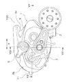
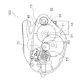
<リールの全体構成>
図1、図2、図3、図4、図5及び図6において、本発明の一実施形態に係る両軸受リールである電動リール100は、外部電源から供給された電力により駆動されるとともに、手巻きリールとして使用するときの電源を内部に有するリールである。また、電動リールは、糸繰り出し長さ又は糸巻取長さに応じて仕掛けの水深を表示する水深表示機能を有するリールである。なお、以降の説明では、釣り糸が繰り出される前後方向を第1方向Xといい、それと直交する左右方向を第2方向Yという。
<Overall configuration of reel>
1, FIG. 2, FIG. 3, FIG. 4, FIG. 5 and FIG. 6, an
電動リール100は、釣り竿に装着可能なリール本体1と、リール本体1に回転自在に装着されたハンドル2と、ハンドル2の内側に配置されたドラグ調整用のスタードラグ3と、リール本体1の内部に配置された糸巻用のスプール10と、を備えている。
The
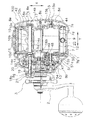
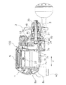
<リール本体の構成>
リール本体1は、図7及び図8に示すように、フレーム7と、第1側カバー8aと、第2側カバー8bと、前カバー9と、カウンタケース4と、を備える。フレーム7は、一体形成された第1側板7aと、第1側板7aと第2方向Yに間隔を隔てて配置された第2側板7bと、第1側板7aと第2側板7bとを連結する第1連結部材7c及び第2連結部材7dと、を有している。第1側カバー8aは、フレーム7のハンドル2の装着側と逆側を覆う。第2側カバー8bは、フレーム7のハンドル2装着側を覆う。前カバー9は、フレーム7の前部を覆う。
<Structure of reel body>
As shown in FIGS. 7 and 8, the reel body 1 includes a
第1側板7aには、図7に示すように、スプール10が通過可能な円形開口7eが形成されている。円形開口7eには、スプール10のスプール軸14の第1端(図7右端)を回転自在に支持するスプール支持部17が芯出しされて装着されている。
As shown in FIG. 7, a circular opening 7e through which the
スプール支持部17は、図7及び図11に示すように、概ね円形の部材である。スプール支持部17は、第1側板7aの外側面に、周方向に間隔を隔てて配置された複数箇所(例えば3箇所)でネジ止め固定されている。スプール支持部17は、スプール軸14の第1端を支持する第1軸受18aを収納する軸受収納部17aと、第1側カバー8aの後述する放熱カバー8dを固定するための2つのボス部17bと、有している。また、スプール支持部17は、スプール10の回転を検出するためのスプールセンサ63が配置されるセンサ配置部17cを有している。軸受収納部17aは、スプール支持部17の外側面に突出して有底筒状に形成される。ボス部17bは、スプール支持部17の外側面から軸方向外方に突出して形成される。
As shown in FIGS. 7 and 11, the
センサ配置部17cは、周囲を囲む壁部17dを有している。センサ配置部17cは、スプールセンサ63が搭載された基板への電気配線が終わると壁部17d内が合成樹脂製の封止剤により封止される。これにより、スプールセンサ63が絶縁される。
The
スプールセンサ63は、例えば、スプール10の回転方向に並べて配置された磁力を検出可能な2つの磁力センサ(例えば、リードスイッチ又はホール素子)63a,63bを有している。スプール10は、スプールセンサ63に対向可能な位置に磁石10aを有している。この磁石10aを検出することによりスプール10の回転速度及び回転位置を検出できる。また、磁力検出センサ63a及び磁力センサ63bのいずれが先に磁石10aを検出したかにより、スプール10の回転方向(糸巻取方向又は糸繰り出し方向)を検出できる。
The
図7及び図8に示すように、第2側板7bは、各種の機構を装着するために設けられている。第2側板7bと第2側カバー8bとの間には、スプール駆動機構13と、後述するクラッチ機構16を制御するクラッチ制御機構20と、キャスティングコントロール機構21と、が設けられている。
As shown in FIGS. 7 and 8, the
第1側板7aと第2側板7bとの間には、スプール10と、クラッチ機構16と、スプール10に釣り糸を均一に巻き付けるための本発明の一実施形態によるレベルワインド機構22と、が設けられている。クラッチ機構16は、スプール10に動力を伝達する動力伝達状態(クラッチオン)と動力を遮断する動力遮断状態(クラッチオフ)とに切り換える。リール本体1の後部において、第1側板7aと第2側板7bとの間には、クラッチ機構16をオンオフ操作するためのクラッチ操作部材11が揺動可能に設けられている。クラッチ操作部材11は、図12に実線で示すクラッチオン位置と、二点鎖線で示すクラッチオフ位置と、の間で揺動する。
Between the
リール本体1は、第2側板7bの外側面に第2側板7bと第2方向Yに間隔を隔てて配置され、第2側カバー8bとの間の空間に上記の機構を装着するための機構装着板19をさらに備えている。機構装着板19は、第2側板7bの外側面にネジ止め固定されている。
The reel body 1 is disposed on the outer surface of the
第1連結部材7cは、第1側板7a及び第2側板7bの下部を前後2箇所で連結する。第2連結部材7dはスプール10の前部を連結する。第1連結部材7cは、板状の部分であり、その左右方向の略中央部分に釣り竿に取り付けるための竿取付脚7fが一体形成されている。第2連結部材7dは、スプール10の前方に配置される概ね円筒状の部分であり、その内部にスプール10駆動用のモータ12(図7及び図9参照)が収容されている。したがって、モータ12は、スプール10の前方に配置される。第2連結部材7dの第1側板7a側の開口は、たとえば、アルミニウム合金等の金属製のモータ保持部15により塞がれている。
The
モータ保持部15は、図7及び図11に示すように、概ね円板形状の部材である。モータ保持部15は、第1側板7aに複数箇所でネジ止め固定されている。モータ保持部15は、モータ12をネジ止め固定する。モータ保持部15は、モータ12の糸繰り出し方向の回転を禁止するためのローラ型のワンウェイクラッチを有する逆転禁止部44が配置されるクラッチ収納部15aと、モータ12の接続端子を配置するための端子配置孔15bと、2つの位置決め突起15cと、を有している。また、モータ保持部15は、1つの取付ボス15dを有している。クラッチ収納部15aは外側面に突出するように有底筒状に形成される。端子配置孔15bは、電気配線が接続された後に封止剤により封止される。モータ保持部15と第2連結部材7dとの間にはOリングなどのシール部材が装着される。これらにより、第2連結部材7d内への液体の浸入が防止される。取付ボス15dは、モータ保持部15の外側面から軸方向外方に突出している。取付ボス15dには、モータ12を冷却するための放熱フィン41がネジ止め固定されている。
As shown in FIGS. 7 and 11, the
放熱フィン41は、例えば、アルミニウム合金製である。放熱フィン41は、表面積を大きくするための複数の線状の凸部41aを外側面に有している。放熱フィン41は、位置決め突起15cに位置決めされる2つの位置決め凹部41bを内側面に有している。また放熱フィン41は、取付ボス15dに向かって延びる取付脚41cを有している。この取付脚41cがモータ保持部15の取付ボス15dにネジ止め固定される。
The
第1側カバー8aは、第1側板7aの外縁部に例えばネジ止めされている。第1側カバー8aの前部下面には、図4に示すように、電源ケーブル接続用のコネクタ43が下向きに装着されている。第1側カバー8aは、電動リール100の側部の後側をカバーするカバー本体8cと、電動リール100の側部の前側をカバーする放熱カバー8dとを有している。カバー本体8cは、第1側板7aにネジ止めされる。
The
放熱カバー8dは、放熱フィン41を覆う。放熱カバー8dは、放熱フィン41の放熱性能を向上するために、複数のスリット8eを有している。スリット8eから放熱フィン41を覗くことができる。放熱カバー8dは、図10に示すように、カバー本体8cではなく、後部がスプール支持部17に複数箇所(例えば2箇所)でネジ止めされ、前部が第1側板7aの前部に1箇所でネジ止めされる。これにより、第1側カバー8a全体のコンパクト化を図ることができ、かつ放熱フィン41を覆う第1側カバー8aの組み立てを行いやすくなる。また、複数のスリット8eが形成される放熱カバー8dにヒケが生じてもカバー本体8cとの姿合わせを行いやすい。さらに、第1側カバー8aがカバー本体8cと放熱カバー8dとに分割されるため、モータ12などへの配線を行いやすくなる。
The
第2側カバー8bには、ハンドル2が一体回転可能に連結される駆動軸30を回転自在に支持するための第1ボス部8fが外方に突出して形成されている。第1ボス部8fの後方には、スプール軸14の第2端を支持する第2ボス部8gが外方に突出して形成されている。第2側カバー8bの第1ボス部8fの上方には、モータ12を複数の段数(例えば31の段数)に制御するための調整レバー5(図3参照)が揺動自在に支持されている。調整レバー5には、図示しないロータリエンコーダが連結されている。図5に示すように、第2側カバー8bと、第2側板7bの下部のそれぞれには、段差8hと段差7gとが間隔をあけて形成される。この隙間がリール本体1の内部に浸入した水を抜くための水抜き孔56として機能する。
A
前カバー9は、第1側板7a及び第2側板7bの前部外側面の上下2箇所で、例えばネジ止め固定されている。前カバー9には、釣り糸通過用の横長の開口9a(図2)が形成されている。
The
<カウンタケースの構成>
カウンタケース4は、図1、図8及び図9に示すように、第1側板7a及び第2側板7bの上部に載置され、第1側板7a及び第2側板7bの外側面にネジ止め固定されている。カウンタケース4の内部には、水深表示用の液晶ディスプレイからなる表示器61が収納されている。また、カウンタケース4の内部には、モータ12及び表示器61を制御する、例えばマイクロコンピュータからなるリール制御部60(図13)が設けられている。
<Configuration of counter case>
As shown in FIGS. 1, 8, and 9, the
カウンタケース4の上面には、図9に示すように、表示器61が露出する矩形の開口4aが形成されている。開口4aは、合成樹脂製の透明なカバー部材4bによりカバーされている。図1に示すように、開口4aの後方(図1下方)には、操作キー部62が配置されている。操作キー部62は、左右に並べて配置されたモータ制御選択スイッチSW1と、0セットスイッチSW2と、高切れスイッチSW3とを有している。モータ制御選択スイッチSW1は、モータ12を張力一定モードで制御する張力モードと、速度一定モードで制御する速度モードとのいずれかを選択するためのスイッチである。0セットスイッチSW2は、釣りを行う前に、仕掛けを水面に配置して水深表示値を0にセットするためのスイッチである。高切れスイッチSW3は、釣り糸が途中で切れたとき、仕掛けを水面に配置して水深表示値を0にセットするためのスイッチである。カウンタケース4は、下面に第2方向Yに沿って形成された溝部4cを有している。
On the upper surface of the
<スプールの構成>
スプール10は、図7に示すように、スプール軸14に一体回転可能に装着されている。スプール10は、筒状の糸巻胴部10bと、糸巻胴部10bの両側に一体形成された大径の第1フランジ部10c及び第2フランジ部10dと、を有している。スプール10は、糸巻胴部10bの直径が第1フランジ部10c及び第2フランジ部10dの直径よりかなり小さい(例えば半分以下の直径)直径を有する深溝型のものである。第1フランジ部10cに前述した磁石10aが固定される。スプール軸14は、糸巻胴部10bの内周部に圧入等の適宜の固定手段により固定されている。
<Spool configuration>
As shown in FIG. 7, the
スプール軸14の第1端は、前述したようにスプール支持部17で第1軸受18aにより支持されている。スプール軸14の第2端(図7右端)は、第2側カバー8bの第2ボス部8gに第2軸受18bにより支持されている。
The first end of the
スプール軸14は、スプール10が固定された大径部14aと、大径部14aの第1端側の第1小径部14bと、大径部14aの第2端側の第2小径部14cと、を有している。大径部14aのスプール固定部分より第2小径部14c側には、クラッチ機構16を構成するクラッチピン16aが径方向を貫通して装着されている。
The
<クラッチ機構及びクラッチ制御機構の構成>
クラッチ機構16は、クラッチピン16aと、後述するピニオンギア32の図7右側端面に径方向に沿って十字に凹んで形成されたクラッチ凹部16bと、を有している。ピニオンギア32は、クラッチ機構16を構成するとともに後述する第1回転伝達機構45を構成している。ピニオンギア32は、スプール軸14方向に沿って、図7に示すクラッチオン位置とクラッチオン位置より図3左側のクラッチオフ位置との間で移動する。クラッチオン位置では、クラッチピン16aがクラッチ凹部16bに係合してピニオンギア32の回転がスプール軸14に伝達され、クラッチ機構16は、クラッチオン状態になる。このクラッチオン状態では、ピニオンギア32とスプール軸14とが一体回転可能になる。また、クラッチオフ位置では、クラッチ凹部16bがクラッチピン16aから離反してピニオンギア32の回転がスプール軸14に伝達されない。このため、クラッチ機構16は、クラッチオフ状態になり、スプール10は自由回転可能になる。
<Configuration of clutch mechanism and clutch control mechanism>
The
クラッチ制御機構20は、クラッチ操作部材11の図12に実線で示すクラッチオン位置と図12に二点鎖線で示すクラッチオフ位置との間の揺動によりクラッチ機構16をクラッチオン状態とクラッチオフ状態とに切り換える。クラッチ制御機構20は、図12に示すように、クラッチ操作部材11のクラッチオン位置とクラッチオフ位置との移動に応じてオン位置(図12実線)とオフ位置(図12二点鎖線)とに回動するクラッチプレート20aを有している。クラッチプレート20aは例えばスプール軸14回りに回動する。クラッチプレート20aには、クラッチ機構16がクラッチオフ状態であることを検出するクラッチセンサ64の検出子42が設けられている。検出子42は、クラッチプレート20aと一体で移動するアーム部42aと、アーム部42aの先端に設けられる磁石42bと、を有している。クラッチセンサ64は、第2側板7bに設けられるセンサ基板55に搭載される。クラッチセンサ64は、磁力を検出可能な磁力センサ(例えば、ホール素子又はリードスイッチ)を有している。クラッチセンサ64は、クラッチプレート20aがオン位置にあると磁石42bは、クラッチセンサ64上に配置される。したがって、クラッチセンサ64は、クラッチ操作部材11がオン位置にあるとオンし、オン位置から外れるとオフする。すなわち、クラッチセンサ64は、クラッチ操作部材11がクラッチオン位置にないことを検出することにより、クラッチ機構16がオフ状態であることを検出する。
The
<レベルワインド機構の構成>
レベルワインド機構22は、図9に示すように、リール本体1に対して回転し釣り糸を前方に繰り出すスプール10の糸巻取方向の回転に連動して釣り糸を第2方向Yに往復移動させる機構である。レベルワインド機構22は、釣り糸ガイド23と、トラバースカム軸24と、ガイドセンサ65と、を備えている。トラバースカム軸24は、外周面に交差する螺旋状溝24aを有し、釣り糸ガイド23を第2方向Yに往復移動させる。ガイドセンサ65は、釣り糸ガイド23が所定位置にあることを検出する。トラバースカム軸24は往復移動機構の一例である。ガイドセンサ65は、釣り糸ガイド検出部の一例である。
<Configuration of level wind mechanism>
As shown in FIG. 9, the
釣り糸ガイド23は、ガイド部25aを有するガイド本体25と、係合部材26と、を有している。ガイド部25aは、筒状に形成され、モータ12の上方にモータ12の中心MCを通り上下方向に延びる中心線CLを挟んで概ね第1方向Xに延びる。ガイド部25aは、この実施形態では、前端部が後端部よりもモータ12から離反するように第1方向Xに沿って斜めに延びる。これにより、ガイド部25aが前上がりに傾斜して配置され、釣り糸からしごかれてガイド部25aの内部に付着する水が抜けやすくなる。
The
ガイド部25aは、内部を釣り糸が通過可能であり、モータ12の中心MCを挟んで配置される筒状の通過部25bと、通過部25bの内部に配置される少なくとも1つの硬質リング部25cと、を有している。この実施形態では、硬質リング部25cは、通過部25bの長手方向長さより長い筒状の部材である。硬質リング部25cの後端は、通過部25bの後端から突出して配置される。硬質リング部25cは、例えば、金属製又は硬質セラミック製である。硬質リング部25cの内周面の両端は断面が円弧状のフィレット形状に形成されている。
The
通過部25bは、カウンタケース4の溝部4cに係合するように配置されるように突出する検出子収納部25dを前端側の上部に有している。検出子収納部25dには、ガイドセンサ65により検出される検出子として機能する磁石28が収納される。磁石28は、釣り糸ガイド23が所定位置に配置されるとガイドセンサ65により検出される。所定位置は、例えば図2に示すように、スプール10の第2方向Yの実質的に中心の位置に対応する位置である。
The
ガイド本体25は、通過部25bから第2連結部材7dに沿って湾曲して第2連結部材7dの前方に配置される。ガイド本体25は、先端に係合部材26が収納される収納部25eを有している。通過部25bの後部及びガイド本体25の上下方向の中間部には、釣り糸ガイド23を第2方向Yに案内する第1ガイド軸27a及び第2ガイド軸27bが貫通している。
The
第1ガイド軸27a及び第2ガイド軸27bは、第2方向Yに沿って配置され、両端が第1側板7a及び第2側板7bに各別に固定される。このように、従来設けられる第2ガイド軸27bに加えて糸繰り出し時に釣り糸が案内される入り口付近に第1ガイド軸27aを設けることにより、釣り糸が絡みにくくなる。また、従来のガイド部に対して前後方向長さが長いガイド部25aの補強を行うことができる。これにより、釣り糸ガイド23が安定して第2方向Yに案内され、釣り糸ガイド23の往復移動がスムーズになり、ガイドセンサ65の位置検出精度が向上する。
The
係合部材26は、上下方向に沿って配置され、先端に螺旋状溝24aに係合する板状の係合部26aを有している。係合部材26は、収納部25eの端部に回動自在に装着される。
The engaging
トラバースカム軸24は、ガイド本体25を貫通して配置される。トラバースカム軸24は、モータ12の中心MCより上方かつ前方に配置される。トラバースカム軸24は、外周面の一部を覆う断面が円弧状のカバー部29によりカバーされる。カバー部29は、ガイド本体25を貫通しており、釣り糸ガイド23の第2方向Yの案内部材としても機能する。トラバースカム軸24が回転すると、釣り糸ガイド23が第2方向Yに往復移動する。トラバースカム軸24はスプール駆動機構13により駆動される。トラバースカム軸24のハンドル装着側の端部には、スプール駆動機構13から駆動力が伝達される従動ギア50(図6及び図7参照)が装着されている。
The
ガイドセンサ65は、図9に示すように、カウンタケース4の下部において、溝部4cの上方に設けられている。ガイドセンサ65は、磁石28の磁力を検出可能な磁力センサ(例えば、ホール素子又はリードスイッチ)を有している。ガイドセンサ65は、釣り糸ガイド23の移動方向の中央位置(概ねスプール10の第2方向Yの中心位置に対向する位置)に配置されている。すなわち、ガイドセンサ65は、所定位置に対応して設けられている。これにより、磁石28をガイドセンサ65が検出すると、釣り糸ガイド23が所定位置に移動したことを検出できる。
As shown in FIG. 9, the
また、レベルワインド機構22は、図13に示すように、所定位置に移動させる移動指令を出力する移動指令出力部60cと、移動指令出力部60cが移動指令を出力すると、トラバースカム軸24を動作させて釣り糸ガイド23を所定位置に移動させる所定位置移動部60dと、をさらに備える。移動指令出力部60c及び所定位置移動部60dは、リール制御部60の機能構成として実現される。
Further, as shown in FIG. 13, the
<スプール駆動機構の構成>
スプール駆動機構13は、スプール10を糸巻取方向に駆動する。また、巻取時にスプール10にドラグ力を発生させて釣り糸の切断を防止する。スプール駆動機構13は、図6、図7及び図8に示すように、モータ12と、モータ12の糸繰り出し方向の回転を禁止する逆転禁止部44と、第1回転伝達機構45と、第2回転伝達機構46と、を備えている。第1回転伝達機構45は、モータ12の回転を減速してスプール10に伝達する。第2回転伝達機構46は、ハンドル2の回転を、第1回転伝達機構45を介して増速してスプール10に伝達する。なお、図6において、矢印は糸巻取方向の各ギアの回転方向を示している。
<Configuration of spool drive mechanism>
The
第1回転伝達機構45は、モータ12の出力軸12aに連結された遊星歯車機構47を有している。遊星歯車機構47は、モータ12の回転を1/20から1/30程度の範囲の減速比で減速してスプール10に伝達する。遊星歯車機構47は、モータ12の出力軸12aに連結された第1遊星減速機構48と、第1遊星減速機構48に連結された第2遊星減速機構49と、を有している。遊星歯車機構47は、第2側板7b及び機構装着板19に両端を回転自在に支持されたケース51内に収納される。ケース51の内周面には、第1遊星減速機構48及び第2遊星減速機構49の内歯ギア51aが形成されている。第1遊星減速機構48の太陽ギアは出力軸12aに一体回転可能に連結される。第2遊星減速機構49の太陽ギアは、第1遊星減速機構48のキャリアに一体回転可能に連結される。ケース51に形成された内歯ギア51aの出力がスプール10とレベルワインド機構22とに伝達される。したがって、第1回転伝達機構45は、回転伝達機構の一例である。第1回転伝達機構45は、モータ12の回転を、ハンドル2の駆動軸30を経由せずにクラッチ機構16を経由してスプール10に伝達するとともに、クラッチ機構16よりもモータ12側でレベルワインド機構22に伝達する回転伝達経路を有している。
The first
第1回転伝達機構45は、第1ギア部材52と、第1ギア部材52に噛み合う第2ギア部材53と、第2ギア部材53に噛み合うピニオンギア32と、をさらに有している。第1ギア部材52は、遊星歯車機構47のケース51の外周に形成されている。したがって、第1ギア部材52は内歯ギアと一体回転可能である。第1ギア部材52は、レベルワインド機構22の従動ギア50にも噛み合っている。第2ギア部材53は、機構装着板19と第2側板7bの外側面との間に配置されている。第2ギア部材53は、第1ギア部材52の回転をピニオンギア32に回転方向を整合させて伝達するための中間ギアである。第2ギア部材53は、機構装着板19に回転自在に支持されている。ピニオンギア32は、第2側板7bにスプール軸14回りに回転自在かつ軸方向移動自在に装着されている。ピニオンギア32は、クラッチ制御機構20により制御されて軸方向にクラッチオン位置とクラッチオフ位置との間で移動する。
The first
第2回転伝達機構46は、図6及び図8に示すように、ハンドル2が一体回転可能に連結された駆動軸30と、駆動ギア31と、第3ギア部材54と、ドラグ機構33と、を有している。
As shown in FIGS. 6 and 8, the second
駆動軸30は、図6に示すように、第2側板7b及び第2側カバー8bの第1ボス部8fに回転自在に支持されている。駆動軸30には、ドラグ機構33のドラグ座金37が一体回転可能に装着されている。駆動軸30の先端には、ハンドル2が一体回転可能に連結されている。また駆動軸30には、第1ワンウェイクラッチ34のラチェットホイール35が一体回転可能が装着されている。ラチェットホイール35は、軸方向内方(図6左方)への移動が規制された状態で装着されている。ラチェットホイール35は、図示しないラチェット爪により糸繰り出し方向の回転が禁止される。駆動軸30の基端は、第2側板7b図示しない軸受により回転自在に支持されている。また、駆動軸30は、ローラ型の第2ワンウェイクラッチ36により第2側カバー8bの第1ボス部8fに支持されている。駆動軸30は、第1ワンウェイクラッチ34により糸繰り出し方向の回転が禁止されている。駆動軸30の糸繰り出し方向の回転を禁止することによりドラグ機構33が動作可能になる。第2ワンウェイクラッチ36は、駆動軸30の糸繰り出し方向の回転を迅速に禁止する。
As shown in FIG. 6, the
駆動ギア31は、駆動軸30に回転自在に装着されている。駆動ギア31は、ドラグ機構33のドラグ座金37により押圧される。駆動ギア31は、ドラグ機構33により糸繰り出し方向の回転が制動される。これにより、スプール10の糸繰り出し方向の回転が制動される。
The
第3ギア部材54は、ハンドル2の回転をスプール10に伝達するために設けられている。第3ギア部材54は、図7に示すように、第2遊星減速機構49のキャリアに一体回転可能に連結されている。第3ギア部材54は、駆動ギア31に噛み合い、ハンドル2の回転を第2遊星減速機構49のキャリアに伝達する。キャリアに伝達された回転は、第1ギア部材52及び第2ギア部材53を介してピニオンギア32に伝達される。第3ギア部材54から第2ギア部材53までの減速比は概ね「1」である。
The
ドラグ機構33は、ドラグ座金37と、ドラグ力を調整するためのスタードラグ3と、を有している。ドラグ機構33は、スプール10の糸繰り出し方向の回転を制動して釣り糸の切断を防止するために設けられる。ドラグ機構33は、設定されたドラグ力以上の力がスプール10に作用するとスプール10を糸繰り出し方向に空転させる。
The
キャスティングコントロール機構21は、図7に示すように、スプール軸14の両端を押圧してスプール10を制動する機構である。
As shown in FIG. 7, the
<電動リールの制御系の構成>
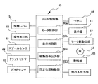
図13に示すように、リール制御部60は、例えば、CPU、RAM、ROM、I/Oインターフェイス等を含むマイクロコンピュータや液晶駆動回路から構成される。リール制御部60は、ソフトウェアで実現される機能構成として、モータ制御部60aと、表示制御部60bと、移動指令出力部60cと、所定位置移動部60dと、を備えている。モータ制御部60aは、調整レバー5の操作量に応じてモータ12を操作量に応じた速度一定または操作量に応じた張力一定に制御する。表示制御部60bは、液晶駆動回路を制御して、釣り糸の糸長(仕掛けの水深)の算出及び表示等の表示器61の表示処理を行う。移動指令出力部60cは、スプール10の糸繰り出し方向の回転に関連してレベルワインド機構22の釣り糸ガイド23を所定位置に移動させる移動指令を出力する。この実施形態では、移動指令出力部60cは、クラッチセンサ64がクラッチオフ状態を検出すると、移動指令を出力する。所定位置移動部60dは、移動指令出力部60cが移動指令を出力すると、モータ12によりトラバースカム軸24を回転させて釣り糸ガイド23を所定位置に移動させる。
<Electric reel control system configuration>
As shown in FIG. 13, the
リール制御部60には、調整レバー5と、操作キー部62と、スプールセンサ63と、クラッチセンサ64と、ガイドセンサ65と、ブザー66と、表示器61と、モータ駆動回路67と、記憶部68と、他の入出力部と、が接続されている。操作キー部62は、前述したように3つのスイッチを有している。スプールセンサ63は、前述したように、スプール10の回転数、回転方向及び回転速度を検出するために設けられる。リール制御部60は、スプールセンサ63から出力されるパルスを計数し、計数出力により、巻初めからのスプール10が何回転したかのスプール回転数X及びスプール10の回転速度を検出できる。
The
ブザー66は、水深表示等で各種の報知を行うために設けられている。モータ駆動回路67は、モータ12をパルス幅変調(Pulse Width Modulation)制御により速度一定又は張力一定駆動するために設けられている。モータ駆動回路67は、モータ12に流れる電流を検出する機能を有している。記憶部68は、例えば、EEPROM(Electrically Erasable Programmable Read-Only Memory)及びフラッシュメモリ等の書換可能な不揮発メモリで構成されている。記憶部68に、糸長計測用のデータおよび棚位置、底位置等のデータが記憶される。
The
<リール制御部の制御動作>
リール制御部60の制御動作について、図14及び図15に示すフローチャートに基づいて説明する。なお、図14か及び図15に示すフローチャートは、制御手順の一例であり、本発明の制御手順はこれに限定されない
電動リール100に電源コードを介して外部電源に接続されると、図14のステップS1において初期設定を行う。この初期設定ではスプールセンサ63の計数値をリセットしたり、各種の変数やフラグをリセットしたり、モータ制御モードを速度モードにし、表示モードを上からモードにする。上からモードは、水面からの仕掛けの水深を表示するモードである。
<Control operation of reel control unit>
The control operation of the
次にステップS2では表示処理を行う。表示処理では、水深表示等の各種の表示処理を行う。ここで、仕掛けの水深が表示器61に表示される。また、速度モードのときには、調整レバー5により操作された速度段数が、張力モードのときには張力段数がそれぞれ表示される。また、速度モードと張力モードとのいずれか制御モードが表示される。
Next, in step S2, display processing is performed. In the display process, various display processes such as water depth display are performed. Here, the water depth of the device is displayed on the
ステップS3では、クラッチセンサ64の検出結果により、クラッチ機構16がクラッチオフ状態であるか否かを判断する。すなわち、クラッチセンサ64がオフするとクラッチ機構16がクラッチオフ状態であると判断する。
In step S3, based on the detection result of the
ステップS4では、操作キー部62のいずれかのスイッチ又は調整レバーが操作されたか否かを判断する。ステップS5ではスプール10が回転しているか否かを判断する。この判断は、スプールセンサ63の出力により判断する。ステップS6ではその他の指令や入力がなされたか否かを判断する。
In step S4, it is determined whether any switch or adjustment lever of the operation
クラッチオフ状態になると、ステップS3からステップS7に移行する。クラッチオフ状態になると、モータ12によりレベルワインド機構22の釣り糸ガイド23を移動させる。このため、ステップS7ではモータ12がすでにオンしているか否かを判断する。モータ12がまだオンしていない場合は、ステップS8に移行し、モータ12をオンしモータ12を回転させる。このとき、クラッチ機構16がオフ状態であるため、モータ12の回転がピニオンギア32に伝達されてもピニオンギア32は空転し、モータ12の回転はスプール10に伝達されない。しかし、モータ12の糸巻取方向の回転が第1ギア部材52を介して従動ギア50に伝達され、トラバースカム軸24が回転する。これにより、釣り糸ガイド23が第2方向Yに移動する。モータ12がすでにオンしている場合は、ステップS7からステップS9に移行する。ステップS9では、釣り糸ガイド23が所定位置に到達したか否かを判断する。この判断は、ガイドセンサ65からの出力により判断する。すなわち、ガイドセンサ65がオンすると、釣り糸ガイド23が前述した所定位置、すなわち、釣り糸ガイド23の移動範囲の中心に位置したことを判断する。釣り糸ガイド23が所定位置に等対していない場合は、ステップS4に移行する。釣り糸ガイド23が所定位置に到達するとステップS9からステップS10に移行し、モータ12をオフする。これにより、釣り糸ガイド23がいずれの位置にあっても、釣り糸を繰り出すときに所定位置に釣り糸ガイド23が配置される。これにより、釣り糸の屈曲の度合いを最小限に抑えることができる。このため、糸巻取時に往復移動する両軸受リールのレベルワインド機構において、糸繰り出し時の抵抗を軽減することができる。
When the clutch is off, the process proceeds from step S3 to step S7. When the clutch is off, the
操作キー部62のいずれかのスイッチ又は調整レバー5が操作された場合にはステップS4からステップS1に移行して操作されたスイッチに応じたスイッチ入力処理を実行する。またスプール10の回転が検出された場合にはステップS4からステップS7に移行する。ステップS7では各動作モード処理を実行する。その他の指令あるいは入力がなされた場合にはステップS5からステップS8に移行してその他の処理を実行する。
When any switch of the operation
図7のステップS7の各動作モード処理では、図14のステップS21でスプール10の回転方向が糸繰り出し方向か否かを判断する。この判断は、スプールセンサ63のいずれの磁石検出素子が先にパルスを発したか否かにより判断する。スプール10の回転方向が糸繰り出し方向と判断するとステップS21からステップS22に移行する。ステップS22では、スプール回転数Xが減少する毎にスプール回転数Xから記憶部68に記憶されたデータを読み出し水深LXを算出する。この水深LXがステップS2の表示処理で表示される。ステップS23では、得られた水深LXが底位置又は棚位置に一致したか、つまり、仕掛けけが底又は棚に到達したか否かを判断する。底位置又は棚位置は、仕掛けけが底又は棚に到達したときに0セットスイッチSWを長押しすることで記憶部68にセットされる。ステップS24では、他のモードか否かを判断する。他のモードではない場合には、各動作モード処理を終わりメインルーチンに戻る。
In each operation mode process in step S7 in FIG. 7, it is determined in step S21 in FIG. 14 whether or not the rotation direction of the
この糸繰り出し時に、従来は、釣り糸ガイドが巻き取り終了時の位置に配置されるが、本実施形態では、巻き取り用のモータ12を利用して釣り糸ガイド23を所定位置に配置している。これにより、釣り糸を繰り出すときに別の駆動手段を設けることなく、釣り糸ガイド23を所定位置に配置できる。
Conventionally, the fishing line guide is disposed at the position at the end of winding when the line is unwound. In this embodiment, the
水深が底位置に一致するとステップS23からステップS25に移行し、仕掛けが底又は棚に到達したことを報知するためにブザー66を鳴らす。他のモードの場合には、ステップS24からステップS26に移行し、指定された他のモードを実行する。
When the water depth matches the bottom position, the process proceeds from step S23 to step S25, and the
スプール10の回転が糸巻き取り方向と判断するとステップS21からステップS277に移行する。ステップS27では、スプール回転数Xから記憶部68に記憶されたデータを読み出し水深LXを算出する。この水深LXがステップS2の表示処理で表示される。ステップS28では、水深が船縁停止位置に一致したか否かを判断する。船縁停止位置まで巻き取っていない場合にはメインルーチンに戻る。船縁停止位置に到達するとステップS28からステップS29に移行する。ステップS29では、仕掛けが船縁にあることを報知するためにブザー66を鳴らす。ステップS30では、モータ12をオフする。これにより魚が釣れたときに取り込みやすい位置に魚が配置される。この船縁停止位置は、例えば水深6m以内で所定時間以上スプール10が停止しているとセットされる。
When the rotation of the
<特徴>
上記実施形態は、下記のように表現可能である。
<Features>
The above embodiment can be expressed as follows.
(A)電動リール100のレベルワインド機構22は、リール本体1に対して回転し釣り糸を前方に繰り出すスプール10の糸巻取方向の回転に連動して釣り糸を左右方向に往復移動させる機構である。レベルワインド機構22は、釣り糸ガイド23と、トラバースカム軸24と、ガイドセンサ65、移動指令出力部60cと、所定位置移動部60dと、を備える。釣り糸ガイド23は、スプール10の前方に配置され、釣り糸を案内する。トラバースカム軸24は、釣り糸ガイドを左右方向に往復移動させる。ガイドセンサ65は、釣り糸ガイド23が所定位置にあることを検出する。移動指令出力部60cは、釣り糸ガイド23を所定位置に移動させる移動指令を出力する。所定位置移動部60dは、移動指令出力部60cが移動指令を出力すると、トラバースカム軸24を回転させて釣り糸ガイド23を所定位置に移動させる。
(A) The
このレベルワインド機構22では、スプール10の糸繰り出し方向の回転に関連して移動指令が出力されると、釣り糸ガイド23が第2方向Yの所定位置に移動する。ここで、移動指令を、例えば、スプールが繰り出し方向に回転するタイミングを含むその前後のタイミングのいずれかで出力することにより、スプールが10糸繰り出し方向の回転に関連して釣り糸ガイド23を所定位置に移動させることができる。また、移動前に釣り糸ガイド23が左右方向のどのような位置に停止していても、所定位置に配置できる。所定位置を、例えば、釣り糸ガイド23の左右方向の移動範囲の中心の位置付近に設定することにより、釣り糸の屈曲の度合いを最小限に抑えることができる。このため、糸巻取時に往復移動するレベルワインド機構22において、糸繰り出し時の抵抗を軽減することができる。
In the
(B)レベルワインド機構22において、所定位置は、スプール10の左右方向の実質的に中心の位置に対応する位置である。この場合には、所定位置がスプール10の左右方向の実質的に中心の位置であるので、釣り糸ガイド23が所定位置からずれた位置に停止していても、移動指令が出力されると釣り糸の屈曲の度合いを最小限に抑えることができる。
(B) In the
(C)レベルワインド機構22において、電動リール100は、クラッチ機構16と、クラッチ操作部材と11、クラッチセンサ64と、を有している。クラッチ機構16は、スプール10を回転操作するためのハンドル2とスプール10とを連結する連結状態及び連結解除する連結解除状態とを取り得る。クラッチ操作部材11は、クラッチ機構16を連結状態にする連結位置と連結解除状態にする連結解除位置とに移動可能にリール本体1に設けられる。クラッチセンサ64は、クラッチ機構16が連結解除状態であるか否かを検出可能である。移動指令出力部60cは、クラッチ機構16が連結解除状態にあることをクラッチセンサ64が検出すると、移動指令を出力する。
(C) In the
この場合には、クラッチ機構16が連結解除状態であることをクラッチセンサ64が検出すると、移動指令が出力され、釣り糸ガイド23が所定位置に移動する。このため、釣り糸を繰り出すときに、自動的に釣り糸ガイドが常に所定位置に移動する。これにより、糸繰り出し時の抵抗を確実に軽減できる。
In this case, when the
(D)レベルワインド機構22において、クラッチセンサ64は、クラッチ操作部材11が連結解除位置にあるか否かによりクラッチ機構16が連結解除状態にあるか否かを検出する。この場合には、通常はスプール軸14とピニオンギア32との間に回転して配置されるクラッチ機構16ではなく、リール本体1に設けられるクラッチ操作部材11により、クラッチ機構16が連結解除状態であることを検出できるので、クラッチセンサ64の構成が簡素になる。
(D) In the
(E)レベルワインド機構22において、両軸受リールは、モータ12によりスプール10を回転駆動する電動リール100である。電動リール100は、第1回転伝達機構45を有する。第1回転伝達機構45は、モータ12の回転を、ハンドル2の駆動軸30を経由せずにクラッチ機構16を経由してスプール10に伝達するとともに、クラッチ機構16よりもモータ12側でトラバースカム軸24に伝達する回転伝達経路を有する。所定位置移動部60dは、移動指令が出力されると、モータ12の回転により回転伝達経路を介して往復移動機構を動作させて、釣り糸ガイドを所定位置に移動させる。
(E) In the
この場合には、スプール10を回転駆動するモータ12と回転伝達経路を用いてトラバースカム軸24を動作させる所定位置移動部60dを構成できる。このため、所定位置移動のための別のアクチュエータが不要になり、所定位置移動部60dの構成が簡素になる。
In this case, a predetermined
(F)レベルワインド機構22において、ガイドセンサ65は、釣り糸ガイド及びリール本体のいずれか一方に設けられるセンサを有する。釣り糸ガイド及びリール本体のいずれか他方には、センサにより検出される検出子が設けられる。この場合には、移動する釣り糸ガイドと固定のリール本体との間にセンサ及び検出子が設けられるので、釣り糸ガイドの位置を精度良く検出できる。
(F) In the
(G)レベルワインド機構22において、検出子は、釣り糸ガイドに設けられる磁石28である。センサは、リール本体1のカウンタケース4に所定位置に対応して設けられ、磁石28を検出可能な磁力センサである。この場合には、移動する釣り糸ガイド23に設けられた磁石28を、固定のカウンタケース4に設けられた磁力センサが検出するので、センサの配線及び構成が簡素になる。
(G) In the
(H)レベルワインド機構22において、移動指令出力部60cは、スプール10が糸繰り出し方向に回転すると、所定のタイミングで移動指令を出力する。この場合には、通常は水深表示用のカウンタケース4を有する両軸受リールに設けられる仕掛けの水深検出用のスプールセンサを利用して移動指令を出力できる。
(H) In the
<他の実施形態>
以上、本発明の一実施形態について説明したが、本発明は上記実施形態に限定されるものではなく、発明の要旨を逸脱しない範囲で種々の変更が可能である。
<Other embodiments>
As mentioned above, although one Embodiment of this invention was described, this invention is not limited to the said embodiment, A various change is possible in the range which does not deviate from the summary of invention.
(a)前記実施形態では、両軸受リールとして電動リールを例に本発明を説明したが、本発明はこれに限定されない。例えば、モータを有さない手巻きの両軸受リールにも本発明を適用できる。この場合、モータにより釣り糸ガイド23を移動させることができないため、所定位置移動部としてとしては、モータ等のアクチュエータが必要である。
(A) In the above embodiment, the present invention has been described by taking an electric reel as an example of a dual-bearing reel, but the present invention is not limited to this. For example, the present invention can be applied to a manually wound double-bearing reel having no motor. In this case, since the
(b)前記実施形態では、クラッチセンサ64から信号により移動指令を出力して釣り糸ガイド23を所定位置に移動させたが、本発明はこれに限定されない。例えば、スプールセンサ63からの信号により、スプール10が糸繰り出し方向に回転したと判断すると、移動指令を出力して釣り糸ガイド23を所定位置に移動させてもよい。この場合、ドラグが作動してスプール10が糸繰り出し方向に回転するときも、釣り糸ガイド23を所定位置に移動させることができる。ただし、スプール10が糸繰り出し方向に回転し始めてから釣り糸ガイド23が所定位置に移動するため、釣り糸の繰り出し初期には釣り糸ガイド23が所定位置に配置されない。
(B) In the above-described embodiment, a movement command is output from the
(c)前記実施形態では、モータ12がスプール10の前方に配置される電動リールを例に本発明を説明したが、本発明はこれに限定されない。スプール内にモータが配置される電動リールやリール本体の外側にモータが配置される電動リールにも本発明を適用できる。
(C) In the above embodiment, the present invention has been described by taking the electric reel in which the
(d)前記実施形態では、釣り糸ガイド23に磁石28が設けられ、リール本体1を構成するカウンタケース4にガイドセンサ65が配置されているが、逆に釣り糸ガイドにガイドセンサを設け、リール本体に磁石を設けてもよい。ただし、固定側に配線を有するセンサを設けるのが好ましい。なお、センサの種類によっては、検出子を設けなくてもよい。たとえば、金属等を検出可能なセンサを用いれば、釣り糸ガイドの少なくとも一部を金属製にすることにより、検出子が不要になる。
(D) In the above embodiment, the
(e)前記実施形態では、トラバースカム軸24に設けられる従動ギア50が第1ギア部材52に噛み合っていたが、本発明はこれに限定されない。例えば、トラバースカム軸24に設けられる従動ギア50を、駆動ギア31と噛み合わせてもよい。この場合、ドラグ作動時にトラバースカム軸24が回転し、釣り糸ガイド23が移動する。また、所定回数のスプール10の糸繰り出し回転を検出する間にガイドセンサ65が釣り糸ガイド23を検出しなかった場合にクラッチ機構16がクラッチオフ状態になったと判断し、移動指令を出力する。
(E) In the above embodiment, the driven
1 リール本体
2 ハンドル
10 スプール
11 クラッチ操作部材
12 モータ
22 レベルワインド機構
23 釣り糸ガイド
24 トラバースカム軸(往復移動機構の一例)
28 磁石
45 第1回転伝達機構
60 リール制御部
60c 移動指令出力部
60d 所定位置移動部
64 クラッチセンサ
65 ガイドセンサ(釣り糸ガイド検出部の一例)
100 電動リール
DESCRIPTION OF SYMBOLS 1
28
100 electric reel
Claims (6)
前記スプールの前方に配置され、釣り糸を案内する釣り糸ガイドと、
前記釣り糸ガイドを前記左右方向に往復移動させる往復移動機構と、
前記釣り糸ガイドが所定位置にあることを検出する釣り糸ガイド検出部と、
前記スプールの糸繰り出し方向の回転に関連して前記釣り糸ガイドを前記所定位置に移動させる移動指令を出力する移動指令出力部と、
前記移動指令出力部が前記移動指令を出力すると、前記往復移動機構を動作させて前記釣り糸ガイドを前記所定位置に移動させる所定位置移動部と、
を備え、
前記電動リールは、
前記スプールを回転操作するためのハンドルと前記スプールとを連結する連結状態及び連結解除する連結解除状態とを取り得るクラッチ機構と、
前記クラッチ機構を前記連結状態にする連結位置と前記連結解除状態にする連結解除位置とに移動可能に前記リール本体に設けられるクラッチ操作部材と、
前記クラッチ機構が前記連結解除状態であるか否かを検出可能なクラッチ状態検出部と、
前記モータの回転を、前記ハンドルの駆動軸を経由せずに前記クラッチ機構を経由して前記スプールに伝達するとともに、前記クラッチ機構よりも前記モータ側で前記往復移動機構に伝達する回転伝達経路と、
を有し、
前記移動指令出力部は、前記クラッチ状態検出部が前記連結解除状態であることを検出すると、前記移動指令を出力し、
前記所定位置移動部は、前記移動指令が出力されると、前記モータの回転により前記回転伝達経路を介して前記往復移動機構を動作させて、前記釣り糸ガイドを前記所定位置に移動させる、
電動リールのレベルワインド機構。 Spool rotating relative to the reel body is provided in an electric reel driven by a motor, a level wind mechanism Ru is reciprocated a fishing line in conjunction with rotation of the yarn winding direction of the spool in the left-right direction,
A fishing line guide disposed in front of the spool and guiding the fishing line;
A reciprocating mechanism for reciprocating the fishing line guide in the left-right direction;
A fishing line guide detection unit for detecting that the fishing line guide is in a predetermined position;
A movement command output unit for outputting a movement command for moving the fishing line guide to the predetermined position in relation to rotation of the spool in the line-feeding direction;
When the movement command output unit outputs the movement command, a predetermined position moving unit that operates the reciprocating mechanism to move the fishing line guide to the predetermined position;
With
The electric reel is
A clutch mechanism capable of taking a connected state for connecting the spool to the handle for rotating the spool and the connected and released state for releasing the connection;
A clutch operating member provided in the reel body so as to be movable between a coupling position for bringing the clutch mechanism into the coupling state and a coupling release position for bringing the coupling mechanism into a released state;
A clutch state detection unit capable of detecting whether or not the clutch mechanism is in the disengaged state;
A rotation transmission path for transmitting rotation of the motor to the spool via the clutch mechanism without passing through the drive shaft of the handle and to the reciprocating mechanism on the motor side of the clutch mechanism; ,
Have
When the movement command output unit detects that the clutch state detection unit is in the disengaged state, the movement command output unit outputs the movement command,
When the movement command is output, the predetermined position moving unit operates the reciprocating mechanism via the rotation transmission path by the rotation of the motor to move the fishing line guide to the predetermined position.
Electric reel level winding mechanism.
前記釣り糸ガイド及び前記リール本体のいずれか他方には、前記センサにより検出される検出子が設けられる、請求項1から3のいずれか1項に記載の電動リールのレベルワインド機構。 The fishing line guide detection unit has a sensor provided on either the fishing line guide or the reel body,
The level winding mechanism of the electric reel according to any one of claims 1 to 3 , wherein a detector detected by the sensor is provided on the other of the fishing line guide and the reel body.
前記センサは、前記リール本体に前記所定位置に対応して設けられ、前記磁石を検出可能な磁力検出部である、請求項4に記載の電動リールのレベルワインド機構。 The detector is a magnet provided on the fishing line guide,
The level reel mechanism of the electric reel according to claim 4 , wherein the sensor is a magnetic force detection unit that is provided in the reel main body corresponding to the predetermined position and is capable of detecting the magnet.
Priority Applications (4)
| Application Number | Priority Date | Filing Date | Title |
|---|---|---|---|
| JP2012136794A JP5961455B2 (en) | 2012-06-18 | 2012-06-18 | Level winding mechanism of double bearing reel, double bearing reel and electric reel |
| TW102104565A TWI558316B (en) | 2012-06-18 | 2013-02-06 | Level winding mechanism for electrical fishing reel, and electrical fishing reel |
| KR1020130027273A KR101928390B1 (en) | 2012-06-18 | 2013-03-14 | Level winding mechanism for electrical fishing reel and electrical fishing reel |
| CN201310105588.2A CN103503850B (en) | 2012-06-18 | 2013-03-28 | Double-bearing fish-line wheel uniform coiling mechanism, double-bearing fish-line wheel and electric fishing reel |
Applications Claiming Priority (1)
| Application Number | Priority Date | Filing Date | Title |
|---|---|---|---|
| JP2012136794A JP5961455B2 (en) | 2012-06-18 | 2012-06-18 | Level winding mechanism of double bearing reel, double bearing reel and electric reel |
Publications (3)
| Publication Number | Publication Date |
|---|---|
| JP2014000030A JP2014000030A (en) | 2014-01-09 |
| JP2014000030A5 JP2014000030A5 (en) | 2015-04-30 |
| JP5961455B2 true JP5961455B2 (en) | 2016-08-02 |
Family
ID=49887709
Family Applications (1)
| Application Number | Title | Priority Date | Filing Date |
|---|---|---|---|
| JP2012136794A Active JP5961455B2 (en) | 2012-06-18 | 2012-06-18 | Level winding mechanism of double bearing reel, double bearing reel and electric reel |
Country Status (4)
| Country | Link |
|---|---|
| JP (1) | JP5961455B2 (en) |
| KR (1) | KR101928390B1 (en) |
| CN (1) | CN103503850B (en) |
| TW (1) | TWI558316B (en) |
Families Citing this family (9)
| Publication number | Priority date | Publication date | Assignee | Title |
|---|---|---|---|---|
| JP6396697B2 (en) * | 2014-06-27 | 2018-09-26 | グローブライド株式会社 | Fishing electric reel |
| JP6587950B2 (en) * | 2016-02-02 | 2019-10-09 | Kddi株式会社 | Program, apparatus, and method capable of detecting time series change point by scalar feature |
| JP6554059B2 (en) * | 2016-03-31 | 2019-07-31 | グローブライド株式会社 | Fishing electric reel |
| JP2017176111A (en) | 2016-03-31 | 2017-10-05 | グローブライド株式会社 | Reel for fishing |
| CN106386725B (en) * | 2016-09-14 | 2022-03-25 | 徐帮奇 | Propelling type fishing gear winding device |
| JP7307693B2 (en) * | 2020-03-24 | 2023-07-12 | グローブライド株式会社 | fishing reel |
| KR20220027735A (en) * | 2020-08-27 | 2022-03-08 | 글로브라이드 가부시키가이샤 | System for controlling fishing information and processing method thereof |
| JP7513571B2 (en) | 2021-06-03 | 2024-07-09 | グローブライド株式会社 | Electric fishing reel |
| CN114589149B (en) * | 2022-03-15 | 2024-01-12 | 万志良 | Quick degreasing device of iron leg for automobile brake block production |
Family Cites Families (8)
| Publication number | Priority date | Publication date | Assignee | Title |
|---|---|---|---|---|
| JPS56169534A (en) * | 1980-05-30 | 1981-12-26 | Daiwa Seiko Co | Both bearing type reel for fishing |
| KR100304065B1 (en) * | 1993-10-21 | 2001-11-22 | 마쯔이 요시유끼 | Drag device of spinning reel for fishing |
| JP2001231417A (en) * | 2000-02-25 | 2001-08-28 | Daiwa Seiko Inc | Electric reel for fishing |
| JP2002247942A (en) * | 2001-02-23 | 2002-09-03 | Johshuya Co Ltd | Electric reel for fishing |
| JP2003235415A (en) * | 2002-02-20 | 2003-08-26 | Shimano Inc | Level winding mechanism of double-bearing reel |
| JP2007089597A (en) * | 2002-03-05 | 2007-04-12 | Daiwa Seiko Inc | Fishing reel |
| JP2003304783A (en) * | 2002-04-18 | 2003-10-28 | Daiwa Seiko Inc | Double bearing reel for fishing |
| CN2872844Y (en) * | 2005-12-30 | 2007-02-28 | 郑岳华 | Closed inner line integrating wheel |
-
2012
- 2012-06-18 JP JP2012136794A patent/JP5961455B2/en active Active
-
2013
- 2013-02-06 TW TW102104565A patent/TWI558316B/en active
- 2013-03-14 KR KR1020130027273A patent/KR101928390B1/en active IP Right Grant
- 2013-03-28 CN CN201310105588.2A patent/CN103503850B/en active Active
Also Published As
| Publication number | Publication date |
|---|---|
| JP2014000030A (en) | 2014-01-09 |
| KR101928390B1 (en) | 2018-12-12 |
| KR20130142061A (en) | 2013-12-27 |
| CN103503850A (en) | 2014-01-15 |
| TWI558316B (en) | 2016-11-21 |
| CN103503850B (en) | 2017-04-05 |
| TW201400011A (en) | 2014-01-01 |
Similar Documents
| Publication | Publication Date | Title |
|---|---|---|
| JP5961455B2 (en) | Level winding mechanism of double bearing reel, double bearing reel and electric reel | |
| JP2014000030A5 (en) | ||
| JP4863891B2 (en) | Double bearing reel | |
| TWI601479B (en) | Electric reel control device | |
| JP5764014B2 (en) | Double bearing reel tension display device | |
| JP2008178315A (en) | Handle shaft-supporting structure of double bearing reel | |
| JP6204041B2 (en) | Double bearing reel | |
| JP2008178315A5 (en) | ||
| JP2013048594A5 (en) | ||
| JP2014183763A5 (en) | ||
| JP6046385B2 (en) | Electric reel level winding mechanism | |
| TWI526154B (en) | Electric reel | |
| JP2014000029A5 (en) | ||
| JP5777867B2 (en) | Fishing reel | |
| TWI622348B (en) | Motor control device for electric reel | |
| JP2019092429A5 (en) | ||
| JP2019092429A (en) | Double bearing reel | |
| JP6284307B2 (en) | Electric reel motor control device | |
| JP5748438B2 (en) | Electric reel | |
| JP2015002689A5 (en) | ||
| JP4366146B2 (en) | Electric reel | |
| JP2005117902A (en) | Electric reel | |
| JP2024078829A (en) | Fishing reel | |
| JP2024078830A (en) | Fishing reel and battery box | |
| JP4368814B2 (en) | Fishing electric reel |
Legal Events
| Date | Code | Title | Description |
|---|---|---|---|
| A521 | Request for written amendment filed |
Free format text: JAPANESE INTERMEDIATE CODE: A523 Effective date: 20150313 |
|
| A621 | Written request for application examination |
Free format text: JAPANESE INTERMEDIATE CODE: A621 Effective date: 20150313 |
|
| A977 | Report on retrieval |
Free format text: JAPANESE INTERMEDIATE CODE: A971007 Effective date: 20160114 |
|
| A131 | Notification of reasons for refusal |
Free format text: JAPANESE INTERMEDIATE CODE: A131 Effective date: 20160119 |
|
| A521 | Request for written amendment filed |
Free format text: JAPANESE INTERMEDIATE CODE: A523 Effective date: 20160309 |
|
| TRDD | Decision of grant or rejection written | ||
| A01 | Written decision to grant a patent or to grant a registration (utility model) |
Free format text: JAPANESE INTERMEDIATE CODE: A01 Effective date: 20160607 |
|
| A61 | First payment of annual fees (during grant procedure) |
Free format text: JAPANESE INTERMEDIATE CODE: A61 Effective date: 20160627 |
|
| R150 | Certificate of patent or registration of utility model |
Ref document number: 5961455 Country of ref document: JP Free format text: JAPANESE INTERMEDIATE CODE: R150 |
|
| R250 | Receipt of annual fees |
Free format text: JAPANESE INTERMEDIATE CODE: R250 |
|
| R250 | Receipt of annual fees |
Free format text: JAPANESE INTERMEDIATE CODE: R250 |
|
| R250 | Receipt of annual fees |
Free format text: JAPANESE INTERMEDIATE CODE: R250 |
|
| R250 | Receipt of annual fees |
Free format text: JAPANESE INTERMEDIATE CODE: R250 |
|
| R250 | Receipt of annual fees |
Free format text: JAPANESE INTERMEDIATE CODE: R250 |
|
| R250 | Receipt of annual fees |
Free format text: JAPANESE INTERMEDIATE CODE: R250 |