JP2017176111A - Reel for fishing - Google Patents
Reel for fishing Download PDFInfo
- Publication number
- JP2017176111A JP2017176111A JP2016071904A JP2016071904A JP2017176111A JP 2017176111 A JP2017176111 A JP 2017176111A JP 2016071904 A JP2016071904 A JP 2016071904A JP 2016071904 A JP2016071904 A JP 2016071904A JP 2017176111 A JP2017176111 A JP 2017176111A
- Authority
- JP
- Japan
- Prior art keywords
- support portion
- side plate
- pinion gear
- handle shaft
- shaft
- Prior art date
- Legal status (The legal status is an assumption and is not a legal conclusion. Google has not performed a legal analysis and makes no representation as to the accuracy of the status listed.)
- Pending
Links
Images


Classifications
-
- A—HUMAN NECESSITIES
- A01—AGRICULTURE; FORESTRY; ANIMAL HUSBANDRY; HUNTING; TRAPPING; FISHING
- A01K—ANIMAL HUSBANDRY; CARE OF BIRDS, FISHES, INSECTS; FISHING; REARING OR BREEDING ANIMALS, NOT OTHERWISE PROVIDED FOR; NEW BREEDS OF ANIMALS
- A01K89/00—Reels
- A01K89/01—Reels with pick-up, i.e. with the guiding member rotating and the spool not rotating during normal retrieval of the line
- A01K89/0102—Reels with pick-up, i.e. with the guiding member rotating and the spool not rotating during normal retrieval of the line with a closed face
-
- A—HUMAN NECESSITIES
- A01—AGRICULTURE; FORESTRY; ANIMAL HUSBANDRY; HUNTING; TRAPPING; FISHING
- A01K—ANIMAL HUSBANDRY; CARE OF BIRDS, FISHES, INSECTS; FISHING; REARING OR BREEDING ANIMALS, NOT OTHERWISE PROVIDED FOR; NEW BREEDS OF ANIMALS
- A01K89/00—Reels
- A01K89/015—Reels with a rotary drum, i.e. with a rotating spool
- A01K89/017—Reels with a rotary drum, i.e. with a rotating spool motor-driven
-
- A—HUMAN NECESSITIES
- A01—AGRICULTURE; FORESTRY; ANIMAL HUSBANDRY; HUNTING; TRAPPING; FISHING
- A01K—ANIMAL HUSBANDRY; CARE OF BIRDS, FISHES, INSECTS; FISHING; REARING OR BREEDING ANIMALS, NOT OTHERWISE PROVIDED FOR; NEW BREEDS OF ANIMALS
- A01K89/00—Reels
- A01K89/01—Reels with pick-up, i.e. with the guiding member rotating and the spool not rotating during normal retrieval of the line
- A01K89/0108—Pick-up details
-
- A—HUMAN NECESSITIES
- A01—AGRICULTURE; FORESTRY; ANIMAL HUSBANDRY; HUNTING; TRAPPING; FISHING
- A01K—ANIMAL HUSBANDRY; CARE OF BIRDS, FISHES, INSECTS; FISHING; REARING OR BREEDING ANIMALS, NOT OTHERWISE PROVIDED FOR; NEW BREEDS OF ANIMALS
- A01K89/00—Reels
- A01K89/015—Reels with a rotary drum, i.e. with a rotating spool
- A01K89/0183—Drive mechanism details
- A01K89/0186—Drive mechanism details with disengageable positive drive components, e.g. a clutch
- A01K89/01902—Gear pair
-
- A—HUMAN NECESSITIES
- A01—AGRICULTURE; FORESTRY; ANIMAL HUSBANDRY; HUNTING; TRAPPING; FISHING
- A01K—ANIMAL HUSBANDRY; CARE OF BIRDS, FISHES, INSECTS; FISHING; REARING OR BREEDING ANIMALS, NOT OTHERWISE PROVIDED FOR; NEW BREEDS OF ANIMALS
- A01K89/00—Reels
- A01K89/015—Reels with a rotary drum, i.e. with a rotating spool
- A01K89/0192—Frame details
-
- A—HUMAN NECESSITIES
- A01—AGRICULTURE; FORESTRY; ANIMAL HUSBANDRY; HUNTING; TRAPPING; FISHING
- A01K—ANIMAL HUSBANDRY; CARE OF BIRDS, FISHES, INSECTS; FISHING; REARING OR BREEDING ANIMALS, NOT OTHERWISE PROVIDED FOR; NEW BREEDS OF ANIMALS
- A01K89/00—Reels
- A01K89/015—Reels with a rotary drum, i.e. with a rotating spool
- A01K89/01931—Spool or spool shaft details
-
- A—HUMAN NECESSITIES
- A01—AGRICULTURE; FORESTRY; ANIMAL HUSBANDRY; HUNTING; TRAPPING; FISHING
- A01K—ANIMAL HUSBANDRY; CARE OF BIRDS, FISHES, INSECTS; FISHING; REARING OR BREEDING ANIMALS, NOT OTHERWISE PROVIDED FOR; NEW BREEDS OF ANIMALS
- A01K89/00—Reels
- A01K89/02—Brake devices for reels
- A01K89/033—Brake devices for reels with a rotary drum, i.e. for reels with a rotating spool
- A01K89/057—Axially engaged
-
- F—MECHANICAL ENGINEERING; LIGHTING; HEATING; WEAPONS; BLASTING
- F16—ENGINEERING ELEMENTS AND UNITS; GENERAL MEASURES FOR PRODUCING AND MAINTAINING EFFECTIVE FUNCTIONING OF MACHINES OR INSTALLATIONS; THERMAL INSULATION IN GENERAL
- F16H—GEARING
- F16H1/00—Toothed gearings for conveying rotary motion
- F16H1/02—Toothed gearings for conveying rotary motion without gears having orbital motion
- F16H1/20—Toothed gearings for conveying rotary motion without gears having orbital motion involving more than two intermeshing members
- F16H1/22—Toothed gearings for conveying rotary motion without gears having orbital motion involving more than two intermeshing members with a plurality of driving or driven shafts; with arrangements for dividing torque between two or more intermediate shafts
Abstract
Description
本発明は魚釣用リールに関する。 The present invention relates to a fishing reel.
魚釣用リールとして両軸受型の魚釣用リールが知られている。従来、一般的な両軸受型の魚釣用リールは、リール本体の左右のフレームと、左右のフレームに装着される左右側板とを備えている。左右側板間には、スプールが回転可能に支持されている。左右側板は金属材または軽量化の面より合成樹脂材により形成されている場合が多い。 A double-bearing type fishing reel is known as a fishing reel. Conventionally, a general dual-bearing fishing reel includes left and right frames of a reel body and left and right side plates attached to the left and right frames. A spool is rotatably supported between the left and right plates. The left and right plates are often formed of a metal material or a synthetic resin material in terms of weight reduction.
左右のフレームのうち、一方のフレームにはハンドル軸が回転可能に設けられている。ハンドル軸にはドラグ機構を介して摩擦結合するドライブギャが設けられている。ドライブギャは、スプールに連結されるピニオンギャに噛合している。 A handle shaft is rotatably provided on one of the left and right frames. A drive gear that frictionally couples via a drag mechanism is provided on the handle shaft. The drive gear meshes with a pinion gear connected to the spool.
このような魚釣用リールでは、ハンドル軸に取り付けられたハンドルを回転操作すると、ドライブギャとピニオンギャとを介してスプールが回転駆動され、スプールに釣糸が巻回される。 In such a fishing reel, when the handle attached to the handle shaft is rotated, the spool is rotated through the drive gear and the pinion gear, and the fishing line is wound around the spool.
また、両軸受型の魚釣用リールとして特許文献1に開示されたものが知られている。この魚釣用リールでは、側板に支持体が固定されている。支持体には、ハンドル軸を支持するハンドル軸支持部と、スプール軸(ピニオンギャ軸)を支持するピニオンギャ軸支持部と、が一体に形成されている。
Moreover, what was disclosed by
この魚釣用リールによれば、ハンドル軸支持部とピニオンギャ軸支持部とを一つの支持体で支持しているため、高負荷時においてもハンドル軸とピニオンギャ軸との間の変形を好適に抑えることができる。 According to this fishing reel, since the handle shaft support portion and the pinion gear shaft support portion are supported by one support body, deformation between the handle shaft and the pinion gear shaft is suitably suppressed even at high loads. be able to.
しかしながら、特許文献1の魚釣用リールでは、支持体が側板に対して固定されていたため、高負荷時にハンドルを操作して釣糸を巻き上げると、支持体にかかる力が側板に及んで側板が変形するおそれがあった。仮に側板が変形してしまうと、フレームと支持体との間で相対的な位置ずれが生じるおそれがあり、ハンドル軸やピニオンギャ軸の回転性能を低下させるおそれがある。
However, in the fishing reel of
また、ハンドル軸やピニオンギャ軸の支持位置の精度は、側板の部品精度や側板に対する支持体の取付精度の影響を受ける。このため、従来の構成では、ハンドル軸やピニオンギャ軸の支持位置の精度を管理するのに好ましくなかった。 In addition, the accuracy of the support position of the handle shaft and the pinion gear shaft is affected by the accuracy of the parts of the side plate and the mounting accuracy of the support to the side plate. For this reason, the conventional configuration is not preferable for managing the accuracy of the support position of the handle shaft and the pinion gear shaft.
本発明は、前記課題を解決するためになされたものであり、高負荷時においてもハンドル軸およびピニオンギャ軸の滑らかな回転性能を維持することができるとともに、ハンドル軸およびピニオンギャ軸の支持位置の精度を確保することができる魚釣用リールを提供することを課題とする。 The present invention has been made to solve the above-described problems, and can maintain the smooth rotation performance of the handle shaft and the pinion gear shaft even at a high load, and the accuracy of the support position of the handle shaft and the pinion gear shaft. It is an object of the present invention to provide a fishing reel capable of ensuring the above.
このような課題を解決する本発明の魚釣用リールは、リール本体の左右のフレームのうち、一方の前記フレームに回転可能に設けられたハンドル軸と、前記ハンドル軸に設けられるドライブギャと、前記ドライブギャに噛合するピニオンギャを介して回転駆動されるスプールと、一方の前記フレームに固定される側板と、前記側板と別体に形成された支持部と、を備え、前記支持部は、前記ハンドル軸を支持するハンドル軸支持部と、前記ピニオンギャのピニオンギャ軸を支持するピニオンギャ軸支持部と、を有し、一方の前記フレームに対して着脱可能に固定されていることを特徴とする。
なお、「ピニオンギャ軸」には、スプールを支持し、スプールから軸方向に延在してピニオンギャを支持するように構成されたスプール軸やスプール軸と別体の支軸またはピニオンギャの軸方向に一体に突設する筒状部も含まれる。
The fishing reel of the present invention that solves such a problem is a handle shaft provided rotatably on one of the left and right frames of the reel body, a drive gear provided on the handle shaft, A spool that is rotationally driven via a pinion gear that meshes with the drive gear, a side plate that is fixed to one of the frames, and a support portion that is formed separately from the side plate. It has a handle shaft support portion that supports a handle shaft and a pinion gear shaft support portion that supports the pinion gear shaft of the pinion gear, and is detachably fixed to one of the frames.
In addition, the “pinion gear shaft” is configured to support the spool and extend in the axial direction from the spool to support the pinion gear, and is integrally formed in the axial direction of the support shaft or pinion gear separate from the spool shaft and the spool shaft. Also included is a cylindrical portion protruding from the tube.
この魚釣用リールによれば、巻き取り操作時に負荷のかかるハンドル軸およびピニオンギャ軸を、側板と別体に形成された支持部を介してフレームに直接支持することができる。したがって、ハンドル軸およびピニオンギャ軸の支持強度を高めることができ、フレームと支持部との間で相対的な位置ずれが生じ難くなる。 According to this fishing reel, it is possible to directly support the handle shaft and pinion gear shaft, which are loaded during the winding operation, on the frame via the support portion formed separately from the side plate. Therefore, the support strength of the handle shaft and the pinion gear shaft can be increased, and relative displacement between the frame and the support portion hardly occurs.
また、前記魚釣用リールにおいて、前記支持部の少なくとも一部は、前記側板から露出しているのがよい。このように構成することで、支持部および側板の意匠デザインの自由度が高まる。また、支持部の少なくとも一部が露出することで、ハンドル軸上にドラグ機構を設ける場合に、支持部の放熱性を意識した構成とすることができる。 In the fishing reel, at least a part of the support portion may be exposed from the side plate. By comprising in this way, the freedom degree of the design design of a support part and a side plate increases. In addition, when at least a part of the support portion is exposed, when the drag mechanism is provided on the handle shaft, the heat dissipation performance of the support portion can be considered.
また、前記魚釣用リールにおいて、前記支持部の全体は、前記側板に覆われているのがよい。このように構成することで、側板の意匠デザインの自由度が高まる。また、支持部の防水性を向上させることができる。 In the fishing reel, the entire support portion may be covered with the side plate. By comprising in this way, the freedom degree of the design design of a side plate increases. Moreover, the waterproofness of a support part can be improved.
また、前記魚釣用リールにおいて、前記支持部は、前記ハンドル軸に回転可能に設けたドライブギャを摩擦結合するドラグ機構を構成する複数の制動板を収容可能であるのがよい。このようにすることで、ハンドルの巻き取り操作時に比較的温度が高くなる部分を支持部に集約することができる。 In the fishing reel, it is preferable that the support portion can accommodate a plurality of braking plates constituting a drag mechanism that frictionally couples a drive gear rotatably provided on the handle shaft. By doing in this way, the part where temperature becomes comparatively high at the time of winding operation of a handle can be collected on a support part.
また、前記魚釣用リールにおいて、前記支持部が金属製であり、前記側板が合成樹脂製であるのがよい。このようにすることで、巻き取り操作時に負荷の掛かる部分の強度向上を図ることができるとともに、軽量化を図ることができる。 In the fishing reel, the support portion may be made of metal, and the side plate may be made of synthetic resin. By doing in this way, while improving the intensity | strength of the part to which a load is applied at the time of winding-up operation, weight reduction can be achieved.
また、前記魚釣用リールにおいて、前記リール本体は、前記スプールを回転駆動する電動モータを備えており、前記側板には、前記電動モータの放熱用の開口部が形成されているのがよい。このようにすることで、電動モータの冷却を促進することができる。 In the fishing reel, the reel body may include an electric motor that rotationally drives the spool, and the side plate may be formed with an opening for heat dissipation of the electric motor. By doing in this way, cooling of an electric motor can be accelerated | stimulated.
また、前記魚釣用リールにおいて、前記開口部の内側には、前記電動モータに接触する放熱部材が配置されているのがよい。このようにすることで、電動モータの冷却をより促進することができる。 In the fishing reel, a heat dissipation member that contacts the electric motor may be disposed inside the opening. By doing in this way, cooling of an electric motor can be promoted more.
本発明の魚釣用リールによれば、ハンドル軸およびピニオンギャ軸の支持強度を支持部によって高めることができ、フレームと支持部との間で相対的な位置ずれが生じ難くなるので、高負荷時においてもハンドル軸およびピニオンギャ軸の滑らかな回転性能を維持することができる。また、フレームと支持部との間で相対的な位置ずれが生じ難くなるので、ハンドル軸およびピニオンギャ軸の支持位置の精度を確保することができる。このことは、耐久性の向上にも寄与する。 According to the fishing reel of the present invention, the support strength of the handle shaft and the pinion gear shaft can be increased by the support portion, and it is difficult for relative displacement between the frame and the support portion to occur. The smooth rotation performance of the handle shaft and the pinion gear shaft can also be maintained. In addition, since it is difficult for relative displacement between the frame and the support portion to occur, it is possible to ensure the accuracy of the support positions of the handle shaft and the pinion gear shaft. This also contributes to improved durability.
また、支持部の少なくとも一部が側板から露出している構成では、支持部および側板の意匠デザインの自由度が高まるので、側板や支持部の形状についての設計が行い易くなる。また、放熱性を意識した設計も容易であり、機能性を向上させることもできる。
また、支持部が側板で覆われている構成では、側板の意匠デザインの自由度が高まるので、側板の形状についての設計が行い易くなる。また、支持部の防水性を向上させることができるので、ハンドル軸およびピニオンギャ軸の滑らかな回転性能を長期的に安定して維持することができる。
Further, in a configuration in which at least a part of the support portion is exposed from the side plate, the degree of freedom in design of the support portion and the side plate is increased, so that the shape of the side plate and the support portion can be easily designed. In addition, the design considering heat dissipation is easy, and the functionality can be improved.
Further, in the configuration in which the support portion is covered with the side plate, the degree of freedom in designing the design of the side plate is increased, so that it is easy to design the shape of the side plate. Further, since the waterproofness of the support portion can be improved, the smooth rotation performance of the handle shaft and the pinion gear shaft can be stably maintained over a long period of time.
また、ドラグ機構を構成する複数の制動板を収容可能な構成では、ハンドルの巻き取り操作時に比較的温度が高くなる部分を支持部に集約することができるので、側板の温度上昇を防止することができる。これにより、側板を介してリール本体の把持が行い易くなる。これにより、魚釣操作性が向上する。 In addition, in the configuration capable of accommodating a plurality of braking plates constituting the drag mechanism, a portion where the temperature is relatively high during the winding operation of the handle can be concentrated on the support portion, thereby preventing an increase in the temperature of the side plate. Can do. This facilitates gripping of the reel body via the side plate. Thereby, fishing operability improves.
また、支持部が金属製であり、側板が合成樹脂製である場合には、巻き取り操作時に負荷の掛かる部分の強度向上を図ることができるとともに、軽量化を図ることができるので、魚釣操作性の向上を図ることができる。また、ハンドル軸およびピニオンギャ軸の支持位置の精度を高次元で確保することができる。また、支持部にドラグ機構が収容される場合には、制動板が過加熱しても支持部に変形を生じることがない。したがって、フレームと支持部との間で相対的な位置ずれが生じ難く、ハンドル軸およびピニオンギャ軸の滑らかな回転性能を長期的に安定して維持することができる。 Further, when the support portion is made of metal and the side plate is made of synthetic resin, it is possible to improve the strength of the portion that is loaded during the winding operation and to reduce the weight, so that fishing The operability can be improved. Further, the accuracy of the support position of the handle shaft and the pinion gear shaft can be ensured in a high dimension. Further, when the drag mechanism is accommodated in the support portion, the support portion is not deformed even if the brake plate is overheated. Therefore, relative displacement between the frame and the support portion hardly occurs, and the smooth rotation performance of the handle shaft and the pinion gear shaft can be stably maintained for a long time.
また、側板に電動モータの放熱用の開口部が形成されている場合には、電動モータの冷却を促進することができるので、電動モータの耐久性を向上させることができる。また、冷却が促進されるので大型の電動モータ(出力の大きい電動モータ)の採用も可能となる。 Moreover, since the cooling of an electric motor can be accelerated | stimulated when the opening part for the radiation of the electric motor is formed in the side plate, durability of an electric motor can be improved. Further, since cooling is promoted, it is possible to adopt a large electric motor (electric motor having a large output).
また、開口部の内側に、電動モータに接触する放熱部材が配置されている場合には、電動モータの冷却をより促進することができるので、電動モータの耐久性をより向上させることができる。 Moreover, when the heat radiating member which contacts an electric motor is arrange | positioned inside the opening part, since cooling of an electric motor can be accelerated | stimulated more, durability of an electric motor can be improved more.
以下、本発明に係る魚釣用リールの実施形態について図面を参照して説明する。以下では、魚釣用リールを魚釣用電動リールに適用した場合を例として説明するが、本発明が適用される魚釣用リールの種類を限定する趣旨ではない。以下の説明において、「前後」「左右」を言うときは、図1,図2示した方向を基準とし、「上下」を言うときは、図2に示した方向を基準とする。 Hereinafter, embodiments of a fishing reel according to the present invention will be described with reference to the drawings. Hereinafter, a case where the fishing reel is applied to an electric fishing reel will be described as an example. However, the type of the fishing reel to which the present invention is applied is not limited. In the following description, when referring to “front and back” and “left and right”, the direction shown in FIG. 1 and FIG. 2 is used as a reference, and when saying “up and down”, the direction shown in FIG.
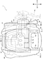
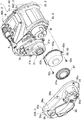
図1に示すように、魚釣用リールは、フレーム2と、このフレーム2を覆うように配設される側板3と、を備えたリール本体1を有している。
フレーム2は、リール本体1の骨格をなす部分であり、左フレーム2a、右フレーム2b、およびスプール5の前方に配設される前フレーム2c(図7参照)を備えてなる。これらの左フレーム2a、右フレーム2b、前フレーム2cは、全体として一体に形成されている。なお、各左フレーム2a、右フレーム2b、前フレーム2cを別体に形成して、固定手段等により一体化してもよいし、部分的に一体に形成してもよい。
As shown in FIG. 1, the fishing reel has a
The
左右フレーム2a,2bは、複数の図示しない支柱を介して一体化されている。下方の図示しない支柱には、釣竿のリールシートに装着される図示しないリール脚が設けられている。
このような左右フレーム2a,2b、前フレーム2cからなるフレーム2は、例えば、アルミニウム合金、マグネシウム合金等の金属材で形成することができる。
左右フレーム2a,2bの上縁には、カウンターケース14が載置されている。
The left and
The
A
前フレーム2cは、左右フレーム2a,2bに開口部(不図示)を有する略円筒状を呈しており、その内部には、電動モータM(図7参照)が収容される。前フレーム2cは、電動モータMを収容するモータケース60(図7参照)の一部として機能している(図8参照)。
The
側板3は、左フレーム2aを覆う左側板30Aと、右フレーム2bを覆う右側板30Bと、前フレーム2cを覆う前側板30Cと、を備え、釣人の手によって握持されたり、保持されたりする部分(釣人の手が接触する部分)となる。
左側板30A、右側板30Bおよび前側板30Cは、個々に合成樹脂製の一体成形品であり、左フレーム2a、右フレーム2bおよび前フレーム2cにそれぞれ装着される。
The
The
さらに、右フレーム2bには、支持部31が着脱可能に固定されている。すなわち、右フレーム2bは、相互に別体とされた2つの部材(右側板30Bおよび支持部31)で覆われている。支持部31は、巻き取り操作されるハンドル70を支持している。支持部31および右側板30Bの詳細は後記する。
Further, a
図1に示すように、左右フレーム2a,2b間には、釣糸が巻回されるスプール5が回転自在に支持されている。
また、スプール5の前方には、電動モータMが配置されており、スプール5は、ハンドル70の巻き取り操作、および電動モータMの回転駆動によって、駆動力伝達機構をなす公知の減速機構G1等を介して釣糸巻き取り方向に回転駆動される。
As shown in FIG. 1, a
Further, an electric motor M is disposed in front of the
スプール5は、釣糸が巻回される釣糸巻回胴部5aを備えており、その両端には、巻回される釣糸を規制するフランジ5b,5cが形成されている。スプール5は、スプール軸5dに図示しない軸受を介して左右フレーム2a,2b間に回転可能に支持されている。
The
スプール5には、減速機構G1および右フレーム2bに設けられた公知の減速機構G2を介して駆動力が伝達されるようになっている。
減速機構G1は、電動モータMの側方に設けられており、電動モータMの出力を減速する。減速機構G1により減速された回転駆動力は、公知の動力伝達部G3を介してスプール軸5dに伝達される。
また、減速機構G2は、右フレーム2b側に設けられており、スプール軸5dの回転駆動力を減速してスプール5に伝達するようになっている。
スプール5には、図8に示すように、ブラケット55を介してピニオンギャ軸9jが連結されている。
A driving force is transmitted to the
The speed reduction mechanism G1 is provided on the side of the electric motor M and decelerates the output of the electric motor M. The rotational driving force decelerated by the speed reduction mechanism G1 is transmitted to the
Further, the speed reduction mechanism G2 is provided on the
As shown in FIG. 8, a
次に、右フレーム2bを覆う支持部31および右側板30Bについて詳細に説明する。
支持部31は、金属製、例えば、アルミニウム合金、マグネシウム合金等からなる一体成形品である。支持部31は、ハンドル軸7の周りに配置される部材であり、右フレーム2bに対して直接固定されている。右側板30Bは、支持部31を囲うように配置される部材であり、右フレーム2bに対して直接固定されている。支持部31は、フレーム2bに対する取付面積(投影面積)が右側板30Bよりも小さくなっている。支持部31はアルマイト加工処理によりカラーリング可能である。
Next, the
The
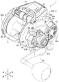
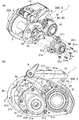
支持部31は、図3(a)(b),図4(a)(b)に示すように、有底円筒状に形成されたハンドル軸支持部31aと、これに連続して有底筒状に形成されたピニオンギャ軸支持部31bと、を備えている。
ハンドル軸支持部31aの内側には、図4(c)に示すように、収容部31a1が形成されている。収容部31a1には、図8に示すように、複数の制動板32aを備えるドラグ機構32、およびドライブギャ8が収容されている。
As shown in FIGS. 3 (a), 3 (b), 4 (a) and 4 (b), the
As shown in FIG. 4C, an accommodating portion 31a1 is formed inside the handle
ハンドル軸支持部31aの底部には、図4(c)に示すように、ハンドル軸7が挿通される断面円形の開口部31cが形成されている。開口部31cの内側には、図7に示すように、軸受けとなるベアリング部材31dを介してドラグ機構32のホルダー32bが支持されている。ホルダー32bは、円板状を呈しており、ハンドル軸7に外嵌されている。これにより、支持部31の一端部となるハンドル軸支持部31aは、ベアリング部材31dおよびホルダー32bを介してハンドル軸7の一端を支持している。ハンドル軸7にはドラグ機構32を介してドライブギャ8が摩擦結合している。なお、ハンドル軸7の基端7aは右フレーム2bに公知のように回転自在に抜け止め支持されている。なお、ハンドル軸7は、公知のように逆転防止機構により、釣糸巻き取り方向の正回転を許容し、釣糸繰り出し方向の逆回転が阻止されるように構成されている。
As shown in FIG. 4C, an
ピニオンギャ軸支持部31bは、図4(a)に示すように、ハンドル軸支持部31aに連続して、ハンドル軸支持部31aの外周面から後方斜め上方に向けてスカート状に拡がるように延在している。ピニオンギャ軸支持部31bの内側には、図8に示すように、ピニオンギャ9が収容されている。ピニオンギャ軸支持部31bの底部31eには、軸受けとなるベアリング部材31fを介してピニオンギャ軸9jの先端部が支持されている。ピニオンギャ軸9jは、スプール5に連結されている。ピニオンギャ9には、ドライブギャ8が噛合している。
As shown in FIG. 4A, the pinion gear
支持部31の外周面には、図4(a)に示すように、ハンドル軸支持部31aの開口部31cを周方向の3方向から囲うように固定用のフランジ部311,312,313が形成されている。各フランジ部311,312,313には、ねじ孔31gが形成されている。各ねじ孔31gには右フレーム2bに締結される固定用ねじ31mが挿通される(図3(a)(b)参照)。上側のフランジ部311のねじ孔31gと、下側のフランジ部312のねじ孔31gとは、図4(a)に示すように、ハンドル軸7の軸心O1(開口部31cの中心)とピニオンギャ軸9jの軸心O2を通る仮想基準線L1について略対称位置に形成されている。また、前側のフランジ部313のねじ孔31gは、仮想基準線L1の延長上に重なるように(略重なるように)形成されている。これにより、ハンドル軸7の軸心O1は、固定ねじ31mによる3つの締結点で周囲を囲まれるように配置される。したがって、ハンドル軸7は、右フレーム2bに対して位置ずれすることなく精度よく支持される。
なお、各フランジ部311,312,313および固定用ねじ31mの頭部は、右フレーム2bに対して右側板30Bを取り付けることで右側板30Bに覆われる。つまり、リール本体1の右側面に露出することがない。これにより、意匠性の向上が図られている。
As shown in FIG. 4A, fixing
The heads of the
フランジ部312,313には、図4(a)に示すように、支持部31を右フレーム2bに取り付ける際の位置決め部として機能する位置決め孔31Gが形成されている。位置決め孔31Gには、右フレーム2bの取付面に突設された図示しない位置決め突部が挿入される。
As shown in FIG. 4A, the
ピニオンギャ軸支持部31bの後部には、角部314,314が形成されている。各角部314には、ねじ孔31jが形成されている。各ねじ孔31jには右フレーム2bに締結される固定用ねじ31nが挿通される(図3(a)(b)参照)。上側の角部314のねじ孔31jと、下側の角部314のねじ孔31jとは、仮想基準線L1について略対称位置に形成されている。これにより、ピニオンギャ軸9jの軸心O2は、固定ねじ31nによって径方向から挟まれるように配置される。したがって、ピニオンギャ軸9jは、右フレーム2bに対して位置ずれすることなく精度よく支持される。
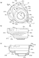
支持部31の外周面には、図4各図に示すように、周方向に亘って段状に張り出す段差面31hが形成されている。支持部31の外周面には、図9に示すように、段差面31hに当接するようにOリング31rが装着されている。Oリング31rは、段差面31hとこれに対向する右側板30Bの開口部33の縁部33aとの間に介設されている。右側板30Bの縁部33aは面取りされている。Oリング31rは、右フレーム2bに右側板30Bを取り付ける際に、縁部33aに押されて弾性変形し、段差面31hとハンドル軸支持部31aの外周面との隅部(角部)に弾力をもって押し当てられる。これにより、支持部31と右側板30Bの開口部33との間がOリング31rによって水密にシールされる。
A stepped
Oリング31rは、図5(b)に示すように、リール本体1を右側面から見たときに、開口部33と支持部31の外周面との隙間に露出している。ここで、開口部33に挿通される支持部31の外周面の寸法は、開口部33との間に若干の隙間を有するように設定されている。これにより、開口部33と支持部31との間にOリング31r(例えば黒色)がアクセントとなって露出し、リール本体1の右側面の意匠性が高められている。
As shown in FIG. 5B, the O-
また、ピニオンギャ軸支持部31bの内側には、図8に示すように、公知のクラッチ機構を構成するスライドプレート9aの一部が収容されている(図3(b)参照)。ピニオンギャ軸支持部31bには、図4(b)に示すように、スライドプレート9aの挿通口31pが形成されている。
Further, inside the pinion gear
以上のような支持部31は、右フレーム2bの図示しない位置決め突部に位置決め孔31Gを係合して右フレーム2bに位置決めされる。そして、フランジ部311,312,313のねじ孔31gに固定用ねじ31mを挿通してこれらを右フレーム2bに締結する。さらに、ピニオンギャ軸支持部31bの各ねじ孔31jに固定用ねじ31nを挿通してこれらを締結する。これによって、支持部31は、右側板30Bから独立して右フレーム2bに直接固定される。
The
次に、右側板30Bについて説明する。右側板30Bは、支持部31と別体に形成されており、右フレーム2bに対して独立して固定される部材である。右側板30Bには、開口部33が形成されている。開口部33は支持部31の外周面に対応した形状とされている。開口部33を通じて、支持部31のハンドル軸支持部31aおよびピニオンギャ軸支持部31bが右側板30Bの右側方に露出する状態で突出している(図2,図8参照)。
Next, the
開口部33の後方上縁部には、右側方に向けて延在する支持部35が形成されている。支持部35は、図5(a)(b)に示すように、側面視で略四角形状を呈している。支持部35には、支持穴35a(図5(a)参照)が形成されている。支持穴35aには、公知のクラッチ機構を操作するための操作レバー38が取り付けられている。操作レバー38は、支持穴35aに挿通される図示しない支軸を介して前後方向に回動操作可能である。操作レバー38を回動操作することによって、スライドプレート9a(図5(a),図8参照)がスライドされ、クラッチ機構の係脱(オンオフ)がなされる。
A
右側板30Bの前部には、図5(b)に示すように、側面視略円形状のモータカバー部34が形成されている。モータカバー部34は、図6各図に示すように、有底円筒状を呈している。モータカバー部34の底部となる右側壁には、電動モータMの放熱用の開口部34aが複数形成されている。モータカバー部34の内側には、図2,図5(b)に示すように、円盤状の放熱部材37が配置されている。放熱部材37は、例えば、アルミニウム合金、マグネシウム合金、銅合金等の金属材で形成されている。放熱部材37は、前記開口部34aを通じて露出している。放熱部材37は、図8,図9に示すようにOリング34pを介して、モータカバー部34の内面に密着している。放熱部材37の左側面は、図8に示すように、モータケース60を構成している蓋体62に接触している。
As shown in FIG. 5B, a
電動モータMは、モータケース60に収容されている。モータケース60は、前記した前フレーム2cと、蓋体62(図7参照)とから構成されている。前フレーム2cは、電動モータMを収容可能な内径を有している。前フレーム2cは、左右フレーム2a,2bと一体に設けられている。蓋体62は、電動モータMの右側部を覆っている。蓋体62は、有底円筒状を呈しており、図8に示すように、前フレーム2cの右縁部63にOリング63aを介してインロー嵌合されている。蓋体62は、図7に示すように、開口縁のフランジ部62aに設けられた各ねじ孔62bにねじ62cを挿通し、これを右フレーム2bに螺合することで右フレーム2bに固定される。電動モータMからの熱は、蓋体62を介して放熱部材37に伝わり、開口部34aを通じて外気に放熱される。
The electric motor M is accommodated in the motor case 60. The motor case 60 includes the above-described
右側板30Bの上端部には、図5(a)に示すように、円弧状の凹部36eが形成されている。凹部36eには、図5(b)に示すように、電動モータMの出力を増減調節する前後方向に回動操作される操作レバー6の端部6aが配置される。
As shown in FIG. 5A, an
以上のような右側板30Bは、図5(b)に示すように、その周縁部に間隔を空けて設けられたねじ孔36aに固定ねじ36bをそれぞれ挿通し、これらを右フレーム2bに螺合することで右フレーム2bに固定される。
As shown in FIG. 5 (b), the
以上説明した本実施形態の魚釣用リールによれば、ハンドル軸7およびピニオンギャ軸9jの支持強度を支持部31によって高めることができ、右フレーム2bと支持部31との間で相対的な位置ずれが生じ難くなるので、高負荷時においてもハンドル軸7およびピニオンギャ軸9jの滑らかな回転性能を維持することができる。このことは、耐久性の向上に寄与する。また、支持部31は右フレーム2bに直接固定されるので、ハンドル軸7およびピニオンギャ軸9jを精度よく支持することができる。したがって、ハンドル軸7およびピニオンギャ軸9jの支持位置の精度を管理し易い。これにより、品質の向上を図ることができるとともに、組付性、生産性に優れた魚釣用リールが得られる。
According to the fishing reel of the present embodiment described above, the support strength of the handle shaft 7 and the
また、右側板30Bは、ハンドル軸7およびピニオンギャ軸9jを支持するための形状や構造を考慮する必要がないので、右側板30Bの設計の自由度ひいてはデザインの自由度を向上させることができる。また、支持部31の放熱性を意識した右側板30Bの設計も容易であり、機能性を向上させることができる。
Further, since the
また、支持部31が右側板30Bから露出しているので、支持部31および側板30Bの意匠デザインの自由度が高まる。これにより、右側板30Bや支持部31の形状についての設計が行い易くなる。また、本実施形態のようにハンドル軸7上にドラグ機構32を設ける場合に、放熱性を意識した設計も容易であり、機能性を向上させることもできる。
Moreover, since the
また、ドラグ機構32を構成する複数の制動板32aおよびドライブギャ8を収容する収容部31a1を支持部31が備えており、ハンドル70の巻き取り操作時に比較的温度が高くなる部分が支持部31に集約されているので、右側板30Bの温度上昇を好適に防止することができる。これにより、右側板30Bを介してリール本体1を好適に把持することができる。これにより、魚釣操作性が向上する。
Further, the
また、支持部31が金属製であり、右側板30Bが合成樹脂製であるので、巻き取り操作時に負荷の掛かる部分の強度向上を図ることができるとともに、軽量化を図ることができるので、魚釣操作性の向上を図ることができる。また、金属製の支持部31により、ハンドル軸7およびピニオンギャ軸9jの支持位置の精度を高次元で確保することができる。
また、支持部31は金属製であるので、実釣時にドラグ機構32の制動板32aが過加熱しても熱の影響で支持部31が変形することもない。したがって、右フレーム2bと支持部31との間で相対的な位置ずれが生じ難く、ハンドル軸7およびピニオンギャ軸9jの滑らかな回転性能を長期的に安定して維持することができる。
In addition, since the
Moreover, since the
また、右側板30Bは、支持部31と別体であるので、支持部31の温度が上昇しても、これが右側板30Bに直接伝わることがなく、右側板30Bが合成樹脂で形成されている構成でありながら、変形を生じることもない。
また、落下等により右側板30Bが損傷した場合には、右側板30Bを単体で部品交換することができる。したがって、メンテナンス性に優れ、部品交換にかかるコストの低減も可能である。
Further, since the
Further, when the
また、右側板30Bの開口部34aを通じて電動モータMの冷却を促進することができるので、電動モータMの耐久性を向上させることができる。また、電動モータMの冷却が促進されるので、大型の電動モータ(出力の大きい電動モータ)を採用することも可能となる。
Further, since the cooling of the electric motor M can be promoted through the
また、右側板30Bの開口部34aの内側に、電動モータMに接触する放熱部材37が配置され開口部34aを通じて放熱部材37が露出しているので、電動モータMの冷却をより促進することができる。したがって、電動モータMの耐久性をより向上させることができる。
Moreover, since the
以上、本発明の実施形態について説明したが、本発明は、上記した実施形態に限定されることはなく、種々変形することが可能である。
例えば、前記実施形態では、右側板30Bの開口部33を通じて支持部31を側方に突出させたが、これに限られることはなく、支持部31を露出させることなく、支持部31の全体あるいは略全体を右側板30Bで側方から覆うように構成してもよい。このように構成することによって、右側板30Bの設計の自由度ひいてはデザインの自由度を向上させることができる。また、支持部31の防水性を向上させることができるので、ハンドル軸7およびピニオンギャ軸9jの滑らかな回転性能を長期的に安定して維持することができる。また、支持部31の仕上げ塗装等も必要なくなり、コストを低減することができる。
As mentioned above, although embodiment of this invention was described, this invention is not limited to above-described embodiment, It can change variously.
For example, in the above-described embodiment, the
また、右側板30Bは、一つの部材で構成したが、これに限られることはなく、二つ以上の部材で構成してもよい。このように構成することによって、右側板30Bの設計の自由度ひいてはデザインの自由度を向上させることができる。
In addition, the
また、支持部31は金属製であるものを示したがこれに限られることはなく、合成樹脂製であってもよい。この場合にも、支持部31が右フレーム2bに直接固定されるので、右フレーム2bと支持部31との間で相対的な位置ずれが生じ難く、ハンドル軸7およびピニオンギャ軸9jの滑らかな回転性能を維持することができる。また、軽量化も可能となる。また、支持部31は補強用の金属部材がインサート成形された合成樹脂製のものや繊維強化樹脂等を採用してもよい。
Moreover, although the
右側板30Bには必ずしも開口部34aを設けなくてもよい。また、開口部34aを設けた場合には、放熱部材37を配置することなく、モータケース60の蓋体62を開口部34aを通じて露出させるように構成してもよい。
The
また、支持部31のピニオンギャ軸支持部を延設して、クラッチ機構を切換操作する操作レバー38を支持するように構成してもよい。このようにすることで操作レバー38の支持強度が高まり、操作性が向上する。
Further, the pinion gear shaft support part of the
また、前記実施形態では、ピニオンギャ軸9jをスプール5に連結し、ピニオンギャ9を挿通する軸部材として説明したが、これに限られることはなく、ピニオンギャ軸9jは、公知のようにピニオンギャ9を挿通するスプール軸5dの延設端部でもよいし、ピニオンギャ9自体の延設筒状端部でもよい。
In the above-described embodiment, the
1 リール本体
2 フレーム
2a 左フレーム
2b 右フレーム
5 スプール
7 ハンドル軸
8 ドライブギャ
9 ピニオンギャ
9j ピニオンギャ軸
3 側板
30B 右側板
31 支持部
31a ハンドル軸支持部
31b ピニオンギャ軸支持部
32 ドラグ機構
32a 制動板
34a 開口部
37 放熱部材
M 電動モータ
1
Claims (7)
前記ハンドル軸に設けられるドライブギャと、
前記ドライブギャに噛合するピニオンギャを介して回転駆動されるスプールと、
一方の前記フレームに固定される側板と、
前記側板と別体に形成された支持部と、を備え、
前記支持部は、
前記ハンドル軸を支持するハンドル軸支持部と、前記ピニオンギャのピニオンギャ軸を支持するピニオンギャ軸支持部と、を有し、
さらに、前記支持部は、一方の前記フレームに対して着脱可能に固定されていることを特徴とする魚釣用リール。 A handle shaft rotatably provided on one of the left and right frames of the reel body;
A drive gear provided on the handle shaft;
A spool that is rotationally driven through a pinion gear meshing with the drive gear;
A side plate fixed to one of the frames;
A support portion formed separately from the side plate,
The support part is
A handle shaft support portion for supporting the handle shaft, and a pinion gear shaft support portion for supporting the pinion gear shaft of the pinion gear,
Further, the fishing reel is characterized in that the support portion is detachably fixed to one of the frames.
前記側板には、前記電動モータの放熱用の開口部が形成されていることを特徴とする請求項1から請求項5のいずれか1項に記載の魚釣用リール。 The reel body includes an electric motor that rotationally drives the spool,
The fishing reel according to any one of claims 1 to 5, wherein the side plate is formed with an opening for heat dissipation of the electric motor.
Priority Applications (5)
| Application Number | Priority Date | Filing Date | Title |
|---|---|---|---|
| JP2016071904A JP2017176111A (en) | 2016-03-31 | 2016-03-31 | Reel for fishing |
| US15/441,879 US9961889B2 (en) | 2016-03-31 | 2017-02-24 | Fishing reel |
| TW106107306A TWI630866B (en) | 2016-03-31 | 2017-03-07 | Fishing reel |
| CN201710136106.8A CN107258718A (en) | 2016-03-31 | 2017-03-08 | Fishing line reel |
| KR1020170039000A KR20170113303A (en) | 2016-03-31 | 2017-03-28 | Fishing reel |
Applications Claiming Priority (1)
| Application Number | Priority Date | Filing Date | Title |
|---|---|---|---|
| JP2016071904A JP2017176111A (en) | 2016-03-31 | 2016-03-31 | Reel for fishing |
Publications (1)
| Publication Number | Publication Date |
|---|---|
| JP2017176111A true JP2017176111A (en) | 2017-10-05 |
Family
ID=59958439
Family Applications (1)
| Application Number | Title | Priority Date | Filing Date |
|---|---|---|---|
| JP2016071904A Pending JP2017176111A (en) | 2016-03-31 | 2016-03-31 | Reel for fishing |
Country Status (5)
| Country | Link |
|---|---|
| US (1) | US9961889B2 (en) |
| JP (1) | JP2017176111A (en) |
| KR (1) | KR20170113303A (en) |
| CN (1) | CN107258718A (en) |
| TW (1) | TWI630866B (en) |
Citations (9)
| Publication number | Priority date | Publication date | Assignee | Title |
|---|---|---|---|---|
| US5397071A (en) * | 1993-07-26 | 1995-03-14 | Daiwa Seiko, Inc. | Motor-operated fishing reel |
| JP2000041546A (en) * | 1998-07-27 | 2000-02-15 | Daiwa Seiko Inc | Double bearing type reel |
| JP2000093054A (en) * | 1998-09-22 | 2000-04-04 | Daiwa Seiko Inc | Reel for fishing |
| JP2004242676A (en) * | 2003-02-12 | 2004-09-02 | Pure Fishing Inc | Multiplier type fishing reel |
| JP2005013114A (en) * | 2003-06-26 | 2005-01-20 | Shimano Inc | Double bearing reel |
| JP2009124942A (en) * | 2007-11-19 | 2009-06-11 | Daiwa Seiko Inc | Fishing reel |
| JP2014000030A (en) * | 2012-06-18 | 2014-01-09 | Shimano Inc | Level wind mechanism of double bearing reel, double bearing reel, and electric reel |
| JP2015027286A (en) * | 2013-06-28 | 2015-02-12 | 株式会社シマノ | Motor control device for electric reel |
| JP2015057997A (en) * | 2013-09-20 | 2015-03-30 | 株式会社シマノ | Double bearing reel |
Family Cites Families (25)
| Publication number | Priority date | Publication date | Assignee | Title |
|---|---|---|---|---|
| US3028717A (en) * | 1957-07-31 | 1962-04-10 | Scott & Sons Co O M | Power mower |
| US4394991A (en) * | 1980-01-24 | 1983-07-26 | Shimano Industrial Company Limited | Double bearing fishing reel |
| JPS6119661Y2 (en) * | 1981-03-28 | 1986-06-13 | ||
| US5427323A (en) * | 1992-10-09 | 1995-06-27 | Daiwa Seiko, Inc. | Fishline length measurement device |
| JP2559947Y2 (en) | 1993-08-06 | 1998-01-19 | ダイワ精工株式会社 | Double bearing type reel |
| US5749533A (en) * | 1995-08-03 | 1998-05-12 | Daniels; John J. | Fishing reel with electronically variable brake for preventing backlash |
| US6045076A (en) * | 1995-08-03 | 2000-04-04 | Daniels; John J. | Fishing reel with electronic antibacklashing features dependent on a sensed line condition |
| JPH0965804A (en) * | 1995-09-01 | 1997-03-11 | Ryobi Ltd | Double bearing-type reel |
| JP3325174B2 (en) * | 1995-12-13 | 2002-09-17 | ダイワ精工株式会社 | Double bearing reel for fishing |
| US6095444A (en) * | 1996-01-24 | 2000-08-01 | Daiwa Seiko, Inc. | Attachment unit for a double bearing type reel for fishing |
| JP3472021B2 (en) * | 1996-02-21 | 2003-12-02 | ダイワ精工株式会社 | Double bearing type reel for fishing |
| JP2000245317A (en) * | 1999-03-04 | 2000-09-12 | Ryobi Ltd | Power reel for fishing |
| US6276532B1 (en) * | 2000-03-15 | 2001-08-21 | Sealed Air Corporation (Us) | Inflatable packaging cushion with a resistance wire |
| US6569283B1 (en) * | 2000-03-15 | 2003-05-27 | Sealed Air Corporation (Us) | Inflator/sealer device for inflatable packaging cushion |
| US6530535B2 (en) * | 2000-03-16 | 2003-03-11 | Daiwa Seiko, Inc. | Fishing reel |
| US7422531B2 (en) * | 2002-03-06 | 2008-09-09 | Tang System | Killer applications of golh, golfishing, golfrisbee, golfball, basedisc, golfrisbee basket |
| US7341215B2 (en) * | 2006-04-20 | 2008-03-11 | Penn Fishing Tackle Mfg. Co. | Fishing reel having a one-piece side plate and bridge |
| EP2371996B1 (en) * | 2008-12-26 | 2016-03-09 | Nihon Parkerizing Co., Ltd. | Method of electrolytic ceramic coating for metal, electrolysis solution for electrolytic ceramic coating for metal, and metallic material |
| US9476465B2 (en) * | 2009-06-29 | 2016-10-25 | Tao Hong | Spatial wedging friction overrunning clutch |
| US20150377179A1 (en) * | 2012-02-08 | 2015-12-31 | Ramesh C. Nayar | Low Grade Thermal Energy Innovative Use |
| US9567488B2 (en) * | 2012-07-03 | 2017-02-14 | Burning Bush Group, Llc | High performance silicon based coating compositions |
| JP6411009B2 (en) | 2013-03-29 | 2018-10-24 | 株式会社シマノ | Reel parts for fishing reels |
| JP6412680B2 (en) | 2013-04-26 | 2018-10-24 | 株式会社シマノ | Double bearing reel |
| US9545088B2 (en) * | 2013-11-29 | 2017-01-17 | Globeride, Inc. | Fishing reel |
| JP6376848B2 (en) | 2014-06-03 | 2018-08-22 | 株式会社シマノ | Double-bearing reel clutch return mechanism |
-
2016
- 2016-03-31 JP JP2016071904A patent/JP2017176111A/en active Pending
-
2017
- 2017-02-24 US US15/441,879 patent/US9961889B2/en active Active
- 2017-03-07 TW TW106107306A patent/TWI630866B/en active
- 2017-03-08 CN CN201710136106.8A patent/CN107258718A/en active Pending
- 2017-03-28 KR KR1020170039000A patent/KR20170113303A/en unknown
Patent Citations (9)
| Publication number | Priority date | Publication date | Assignee | Title |
|---|---|---|---|---|
| US5397071A (en) * | 1993-07-26 | 1995-03-14 | Daiwa Seiko, Inc. | Motor-operated fishing reel |
| JP2000041546A (en) * | 1998-07-27 | 2000-02-15 | Daiwa Seiko Inc | Double bearing type reel |
| JP2000093054A (en) * | 1998-09-22 | 2000-04-04 | Daiwa Seiko Inc | Reel for fishing |
| JP2004242676A (en) * | 2003-02-12 | 2004-09-02 | Pure Fishing Inc | Multiplier type fishing reel |
| JP2005013114A (en) * | 2003-06-26 | 2005-01-20 | Shimano Inc | Double bearing reel |
| JP2009124942A (en) * | 2007-11-19 | 2009-06-11 | Daiwa Seiko Inc | Fishing reel |
| JP2014000030A (en) * | 2012-06-18 | 2014-01-09 | Shimano Inc | Level wind mechanism of double bearing reel, double bearing reel, and electric reel |
| JP2015027286A (en) * | 2013-06-28 | 2015-02-12 | 株式会社シマノ | Motor control device for electric reel |
| JP2015057997A (en) * | 2013-09-20 | 2015-03-30 | 株式会社シマノ | Double bearing reel |
Also Published As
| Publication number | Publication date |
|---|---|
| US20170280696A1 (en) | 2017-10-05 |
| TWI630866B (en) | 2018-08-01 |
| CN107258718A (en) | 2017-10-20 |
| TW201735786A (en) | 2017-10-16 |
| KR20170113303A (en) | 2017-10-12 |
| US9961889B2 (en) | 2018-05-08 |
Similar Documents
| Publication | Publication Date | Title |
|---|---|---|
| US8235320B2 (en) | Dual-bearing reel | |
| KR102230789B1 (en) | Dual-bearing reel | |
| KR101979018B1 (en) | Fishing-reel reel unit and fishing reel | |
| KR101966231B1 (en) | Fishing-reel reel unit and fishing reel | |
| EP1500330B1 (en) | Dual-bearing reel | |
| EP2708120B1 (en) | Spinning reel | |
| US6959887B2 (en) | Spool for dual-bearing reel | |
| CN107258719B (en) | Electric reel for fishing | |
| JP2003225039A (en) | Reel body of spinning reel | |
| JP2017176111A (en) | Reel for fishing | |
| JP6026870B2 (en) | Fishing reel | |
| KR102374340B1 (en) | Electrically driven reel for fishing | |
| JP7420702B2 (en) | double bearing reel | |
| JP6267874B2 (en) | Spool braking device for double-bearing reel | |
| JP2017176112A (en) | Electric reel for fishing | |
| JP7187196B2 (en) | electric fishing reel | |
| JP2016021875A (en) | Double bearing reel | |
| JP2016021875A5 (en) | ||
| JP5754999B2 (en) | Motor cooling device for electric reel | |
| JPH0965804A (en) | Double bearing-type reel | |
| JP3797832B2 (en) | Centrifugal braking device for double-bearing reel | |
| JP2006042741A (en) | Part assembly of reel for fishing | |
| JP2006238713A (en) | Handle grip of fishing reel | |
| JP2017192359A (en) | Fishing reel | |
| JP2001037382A (en) | Reel for fly fishing |
Legal Events
| Date | Code | Title | Description |
|---|---|---|---|
| A621 | Written request for application examination |
Free format text: JAPANESE INTERMEDIATE CODE: A621 Effective date: 20180518 |
|
| A977 | Report on retrieval |
Free format text: JAPANESE INTERMEDIATE CODE: A971007 Effective date: 20190125 |
|
| A131 | Notification of reasons for refusal |
Free format text: JAPANESE INTERMEDIATE CODE: A131 Effective date: 20190226 |
|
| A521 | Request for written amendment filed |
Free format text: JAPANESE INTERMEDIATE CODE: A523 Effective date: 20190425 |
|
| A02 | Decision of refusal |
Free format text: JAPANESE INTERMEDIATE CODE: A02 Effective date: 20190611 |