JP6411009B2 - Reel parts for fishing reels - Google Patents
Reel parts for fishing reels Download PDFInfo
- Publication number
- JP6411009B2 JP6411009B2 JP2013073705A JP2013073705A JP6411009B2 JP 6411009 B2 JP6411009 B2 JP 6411009B2 JP 2013073705 A JP2013073705 A JP 2013073705A JP 2013073705 A JP2013073705 A JP 2013073705A JP 6411009 B2 JP6411009 B2 JP 6411009B2
- Authority
- JP
- Japan
- Prior art keywords
- reel
- inner member
- outer member
- fixed
- fishing
- Prior art date
- Legal status (The legal status is an assumption and is not a legal conclusion. Google has not performed a legal analysis and makes no representation as to the accuracy of the status listed.)
- Active
Links
- BXLAHDKMWUFGPW-UHFFFAOYSA-N CCC(C)=C1CCCC1 Chemical compound CCC(C)=C1CCCC1 BXLAHDKMWUFGPW-UHFFFAOYSA-N 0.000 description 1
Images


Classifications
-
- A—HUMAN NECESSITIES
- A01—AGRICULTURE; FORESTRY; ANIMAL HUSBANDRY; HUNTING; TRAPPING; FISHING
- A01K—ANIMAL HUSBANDRY; CARE OF BIRDS, FISHES, INSECTS; FISHING; REARING OR BREEDING ANIMALS, NOT OTHERWISE PROVIDED FOR; NEW BREEDS OF ANIMALS
- A01K89/00—Reels
- A01K89/006—Hand crank features
-
- A—HUMAN NECESSITIES
- A01—AGRICULTURE; FORESTRY; ANIMAL HUSBANDRY; HUNTING; TRAPPING; FISHING
- A01K—ANIMAL HUSBANDRY; CARE OF BIRDS, FISHES, INSECTS; FISHING; REARING OR BREEDING ANIMALS, NOT OTHERWISE PROVIDED FOR; NEW BREEDS OF ANIMALS
- A01K89/00—Reels
-
- A—HUMAN NECESSITIES
- A01—AGRICULTURE; FORESTRY; ANIMAL HUSBANDRY; HUNTING; TRAPPING; FISHING
- A01K—ANIMAL HUSBANDRY; CARE OF BIRDS, FISHES, INSECTS; FISHING; REARING OR BREEDING ANIMALS, NOT OTHERWISE PROVIDED FOR; NEW BREEDS OF ANIMALS
- A01K89/00—Reels
- A01K89/01—Reels with pick-up, i.e. with the guiding member rotating and the spool not rotating during normal retrieval of the line
-
- A—HUMAN NECESSITIES
- A01—AGRICULTURE; FORESTRY; ANIMAL HUSBANDRY; HUNTING; TRAPPING; FISHING
- A01K—ANIMAL HUSBANDRY; CARE OF BIRDS, FISHES, INSECTS; FISHING; REARING OR BREEDING ANIMALS, NOT OTHERWISE PROVIDED FOR; NEW BREEDS OF ANIMALS
- A01K89/00—Reels
- A01K89/015—Reels with a rotary drum, i.e. with a rotating spool
-
- F—MECHANICAL ENGINEERING; LIGHTING; HEATING; WEAPONS; BLASTING
- F16—ENGINEERING ELEMENTS AND UNITS; GENERAL MEASURES FOR PRODUCING AND MAINTAINING EFFECTIVE FUNCTIONING OF MACHINES OR INSTALLATIONS; THERMAL INSULATION IN GENERAL
- F16H—GEARING
- F16H55/00—Elements with teeth or friction surfaces for conveying motion; Worms, pulleys or sheaves for gearing mechanisms
- F16H55/02—Toothed members; Worms
- F16H55/06—Use of materials; Use of treatments of toothed members or worms to affect their intrinsic material properties
-
- F—MECHANICAL ENGINEERING; LIGHTING; HEATING; WEAPONS; BLASTING
- F16—ENGINEERING ELEMENTS AND UNITS; GENERAL MEASURES FOR PRODUCING AND MAINTAINING EFFECTIVE FUNCTIONING OF MACHINES OR INSTALLATIONS; THERMAL INSULATION IN GENERAL
- F16H—GEARING
- F16H55/00—Elements with teeth or friction surfaces for conveying motion; Worms, pulleys or sheaves for gearing mechanisms
- F16H55/02—Toothed members; Worms
- F16H55/17—Toothed wheels
Landscapes
- Life Sciences & Earth Sciences (AREA)
- Environmental Sciences (AREA)
- Animal Husbandry (AREA)
- Biodiversity & Conservation Biology (AREA)
Description
本発明は、リール部品、特に、釣り用リールに用いられるリール部品に関する。 The present invention relates to a reel component, particularly a reel component used for a fishing reel.
釣り用リールには、強度が必要でかつ軽量化を求められるリール部品が用いられる。例えば、ハンドルの回転をスプールに伝達する駆動ギアは、ギア歯の強度が高くないと、引きが強い魚などを釣り上げることができない。しかし、全体的に強度が高い部材を用いると、軽量化を図りにくい。そこで、駆動ギアの強度を維持して軽量化を図るために、スピニングリールのリール部品としての駆動ギアにおいて、アルミニウム合金製の円板部と、円板部の外周部に亜鉛合金製の歯部と、を備えたものが従来知られている(例えば、特許文献1参照)。従来のリール部品は、歯部を円板部の外周部にアウトサート成型によって一体形成している。 For fishing reels, reel parts that require strength and are required to be lighter are used. For example, a drive gear that transmits the rotation of a handle to a spool cannot catch a fish that has a strong pull unless the strength of the gear teeth is high. However, when a member having high strength as a whole is used, it is difficult to reduce the weight. Therefore, in order to reduce the weight while maintaining the strength of the drive gear, in the drive gear as a reel component of a spinning reel, a disk part made of aluminum alloy and a tooth part made of zinc alloy on the outer peripheral part of the disk part Are conventionally known (see, for example, Patent Document 1). In a conventional reel part, the tooth part is integrally formed on the outer peripheral part of the disk part by outsert molding.
一般にアルミニウムなどの軽合金は、耐食性を向上させるために陽極酸化皮膜等の表面処理膜が形成されている。このような表面処理膜が形成された円板部に亜鉛合金を一体形成すると、表面処理膜が損傷してリール部品の表面処理膜の性能が劣化するおそれがある。 In general, a light alloy such as aluminum is provided with a surface treatment film such as an anodized film in order to improve corrosion resistance. If the zinc alloy is integrally formed on the disk portion on which such a surface treatment film is formed, the surface treatment film may be damaged, and the performance of the surface treatment film of the reel component may be deteriorated.
また、アウトサート成形によってギア歯を形成すると、ギア歯の精度が低くなるおそれがある。ギア歯の精度が低くなると、駆動ギアに噛み合うギアとのかみ合いが悪くなり、駆動ギアの回転によって回転する、たとえばスプールまたはロータなどの回転部品が滑らかに回転しにくい。 Further, when gear teeth are formed by outsert molding, the accuracy of the gear teeth may be lowered. When the accuracy of the gear teeth is lowered, the meshing with the gear meshing with the drive gear becomes worse, and a rotating component such as a spool or a rotor that rotates by the rotation of the drive gear is difficult to rotate smoothly.
本発明の課題は、リール部品の精度、強度及び表面処理膜の性能を維持してリール部品の軽量化を図ることにある。 An object of the present invention is to reduce the weight of a reel component while maintaining the accuracy and strength of the reel component and the performance of the surface treatment film.
本発明に係る釣り用リールのリール部品は、内側部材と、外側部材と、を備える。内側部材は、表面処理膜を有する。外側部材は、内側部材の外周側に固定され、内側部材に固定された後に加工された加工部を有する。 The reel component of the fishing reel according to the present invention includes an inner member and an outer member. The inner member has a surface treatment film. The outer member is fixed to the outer peripheral side of the inner member and has a processed portion processed after being fixed to the inner member.
このリール部品では、表面処理膜を有する内側部材に外側部材を固定してから外側部材の加工部が加工される。これによって、表面処理膜が影響を受けなくなり、表面処理膜の性能を維持できるとともに、加工部の精度を高く維持できる。また、内側部材に比重が小さい材料を用い、外側部材に剛性が高いものを用いることによって、強度を維持して軽量化を図ることができる。 In this reel component, the outer member is fixed to the inner member having the surface treatment film, and then the processed portion of the outer member is processed. As a result, the surface treatment film is not affected, the performance of the surface treatment film can be maintained, and the accuracy of the processed portion can be maintained high. Further, by using a material having a small specific gravity for the inner member and using a material having high rigidity for the outer member, the strength can be maintained and the weight can be reduced.
加工部はギア歯を有してもよい。この場合には、ギア歯の強度を維持できる。 The processed part may have gear teeth. In this case, the strength of the gear teeth can be maintained.
ギア歯は、機械加工によって形成されてもよい。この場合には、ギア歯を高精度に形成できる。 The gear teeth may be formed by machining. In this case, the gear teeth can be formed with high accuracy.
ギア歯は、鍛造加工によって形成されてもよい。この場合に、機械加工で形成するとコストが増加するフェースギア歯をコストの増加を抑えて形成できる。 The gear teeth may be formed by forging. In this case, face gear teeth whose cost increases when formed by machining can be formed while suppressing an increase in cost.
内側部材は、表面処理膜としての耐食皮膜を有する第1金属製であり、外側部材は、ギア歯を有し、第1金属よりも比重が大きく剛性が高い第2金属製であってもよい。この場合には、ギア歯の強度及び耐食性を維持してギアの軽量化を図ることができる。 The inner member may be made of a first metal having a corrosion-resistant film as a surface treatment film, and the outer member may be made of a second metal having gear teeth and having a specific gravity and higher rigidity than the first metal. . In this case, it is possible to reduce the gear weight while maintaining the strength and corrosion resistance of the gear teeth.
内側部材は、外側部材に嵌合し、圧入によって外側部材に固定されてもよい。この場合には、圧入によって内側部材と外側部材とを強固に固定できる。 The inner member may be fitted to the outer member and fixed to the outer member by press fitting. In this case, the inner member and the outer member can be firmly fixed by press-fitting.
内側部材は、外側部材に向けて塑性変形させることによって外側部材に固定されてもよい。この場合には、例えば、かしめ固定等の塑性変形によって内側部材と外側部材とを強固に固定できる。 The inner member may be fixed to the outer member by plastic deformation toward the outer member. In this case, for example, the inner member and the outer member can be firmly fixed by plastic deformation such as caulking.
内側部材は、外側部材に接着によって固定されてもよい。この場合には、内側部材と外側部材とを容易に固定できる。また、上記の圧入または塑性変形による固定と接着とを組み合わせることによって、内側部材と外側部材とをさらに強固に固定できる。 The inner member may be fixed to the outer member by adhesion. In this case, the inner member and the outer member can be easily fixed. Moreover, the inner member and the outer member can be more firmly fixed by combining the above-described fixing by press-fitting or plastic deformation and adhesion.
内側部材は、雄ねじ部を有し、外側部材は、雄ねじ部に螺合する雌ねじ部を有してもよい。この場合には、ねじ係合によって内側部材と外側部材とを容易に固定できる。 The inner member may have a male screw portion, and the outer member may have a female screw portion that is screwed into the male screw portion. In this case, the inner member and the outer member can be easily fixed by screw engagement.
内側部材及び外側部材は、互いに係合して回り止めする回り止め部をそれぞれ有してもよい。この場合には、内側部材と外側部材とが回り止めされるので、圧入、塑性変形、接着などによって内側部材と外側部材とを固定しても、内側部材と外側部材とを確実に一体回転させることができる。 Each of the inner member and the outer member may have a rotation preventing portion that engages with each other and stops rotation. In this case, since the inner member and the outer member are prevented from rotating, even if the inner member and the outer member are fixed by press-fitting, plastic deformation, adhesion, or the like, the inner member and the outer member are reliably rotated integrally. be able to.
内側部材は、釣り用リールのハンドルと連動して回転する駆動軸に装着され、外側部材のギア歯は、釣り用リールのスプール軸回りに回転するピニオンギアにかみ合ってもよい。この場合には、両軸受リール、スピニングリールまたは片軸受リールの駆動ギアの精度、強度及び表面処理膜の性能を維持して駆動ギアの軽量化を図ることができる。 The inner member may be mounted on a drive shaft that rotates in conjunction with the fishing reel handle, and the gear teeth of the outer member may mesh with a pinion gear that rotates about the spool shaft of the fishing reel. In this case, it is possible to reduce the weight of the drive gear while maintaining the accuracy, strength, and performance of the surface treatment film of the dual-bearing reel, spinning reel, or single-bearing reel.
釣り用リールは、ハンドルの軸芯と平行な軸芯回りに回転するスプールを有する両軸受リールであってもよい。内側部材は、両軸受リールの駆動軸に連動して回転可能に駆動軸に装着される。この場合に、両軸受リールにおいて、駆動ギアの精度、強度及び表面処理膜の性能を維持して駆動ギアの軽量化を図ることができる。 The fishing reel may be a dual-bearing reel having a spool that rotates about an axis parallel to the axis of the handle. The inner member is rotatably mounted on the drive shaft in conjunction with the drive shaft of the dual-bearing reel. In this case, in the dual-bearing reel, the drive gear can be reduced in weight while maintaining the accuracy and strength of the drive gear and the performance of the surface treatment film.
釣り用リールは、ハンドルの軸芯と食い違う軸方向に前後往復移動するスプールを有するスピニングリールであり、内側部材は、スピニングリールの駆動軸に一体回転可能に装着されてもよい。この場合に、スピニングリールにおいて、駆動ギアの精度、強度及び表面処理膜の性能を維持して駆動ギアの軽量化を図ることができる。 The fishing reel may be a spinning reel having a spool that reciprocates back and forth in an axial direction that is different from the axis of the handle, and the inner member may be attached to a driving shaft of the spinning reel so as to be integrally rotatable. In this case, in the spinning reel, the drive gear can be reduced in weight while maintaining the accuracy, strength, and surface treatment film performance of the drive gear.
本発明によれば、リール部品の精度、強度及び表面処理膜の性能を維持してリール部品の軽量化を図ることができる。 According to the present invention, the reel component can be reduced in weight while maintaining the accuracy and strength of the reel component and the performance of the surface treatment film.
<第1実施形態>
<全体構成>
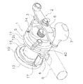
図1において、本発明の第1実施形態が採用された両軸受リールは、たとえば、ジギングに使用する中型の丸型リールである。丸型リールは、リール本体1と、リール本体1の側方に配置されたスプール回転用のハンドル2と、ハンドル2のリール本体1側に配置されたスタードラグ3とを備えている。リール本体1には、スプール15が回転自在に装着されている。リール本体1は、釣り竿取付脚4を介して釣り竿Rに装着され得る。
<First Embodiment>
<Overall configuration>
In FIG. 1, the dual-bearing reel in which the first embodiment of the present invention is adopted is, for example, a medium-sized round reel used for jigging. The round reel includes a
リール本体1は、図2に示すように、フレーム5と、第1側カバー13と、第2側カバー14と、機構装着板16と、を有している。フレーム5は、所定の間隔をあけて配置された第1側板10及び第2側板11と、第1側板10と第2側板11を後部で連結する後部連結部材12a、下部で連結する下部連結部材12b、及び前部で連結する前部連結部材12cと、を有している。第1側カバー13は、第1側板10の外方を覆うように第1側板と一体形成されている。第2側カバー14は、第2側板11の外方を覆うように第2側板11に固定されている。機構装着板16は第2側板11に配置され、機構装着板16と第2側カバー14との間には、後述する各種機構を収納するための空間が形成されている。
As shown in FIG. 2, the
フレーム5はダイキャスト成形により得られ、第2側カバー14は、金属薄板をプレス成形して得られる。第1側板10、第2側板11及び第1側カバー13は、それぞれ側面から見て略円形をなしており、外周面はたとえば旋盤等を用いて機械加工されている。第2側カバー14及び機構装着板16は、図1乃至図3に示すように、側面から見て略円形の一部が径方向にそれぞれ突出した形状である。第2側カバー14は、駆動軸30(後述)の装着部分を中心に軸方向外方にも膨出している。
The
後部連結部材12a、下部連結部材12b及び前部連結部材12cは、第1側板10及び第2側板11の外周に沿う形状で第1側板10及び第2側板11と一体で形成された板状の部材である。後部連結部材12a、下部連結部材12b及び前部連結部材12cは、3か所で第1側板10及び第2側板11を連結している。このように第1側板10及び第2側板11と、後部連結部材12a、下部連結部材12b及び前部連結部材12cと、を一体で形成することで、リール本体1に大きな荷重が作用しても撓み等の変形が生じがたく、巻上げ効率の低下が抑制される。この連結部材12a,12b,12cの外周部も第1側板10、第2側板11及び第1側カバー13と一体で機械加工されている。
The
下部の連結部材12bには釣り竿取付脚4が固定されている。釣り竿取付脚4は、フレーム5の第1側板10及び第2側板11の間の中心位置に沿って前後方向に配置されている。この中心位置は、スプール15の糸巻部分の中心位置でもある。後部の連結部材12aには、リールを釣り竿Rとともに保持するための合成樹脂製のサムレスト17が装着されている。
A fishing
サムレスト17は、後部連結部材12aの上部と後部とに接するように形成され、かつ後部が第1側板10及び第2側板11から径方向外方、つまり後方に突出している。サムレスト17の上面後部は、下方に凸に湾曲しながら傾斜している。また、サムレスト17の上面後部の左端及び右端は、後方への突出量が左側にいくにつれて徐々に減少している。
The
このような形状のサムレスト17を設け、このサムレスト17にたとえば左手の親指を置いて他の指で釣り竿Rをつかみ、釣り竿Rとともにリール本体1を握ることで、バーチカルジギング時等に釣り竿Rをリール本体1とともに確実に保持できる。
The
ハンドル2は、図2及び図3に示すように、駆動軸30の先端に回転不能に装着されたクランクアーム6と、クランクアーム6の一端にクランクアーム6の一端部と直交する把手軸芯回りに回転自在に装着されたハンドル把手7とを有している。ハンドル2において、ハンドル把手7の基端部の回転平面がクランクアーム6の駆動軸30への固定部分の回転平面よりリール本体1側に接近している。このことにより、ハンドル把手7と釣り竿Rとの距離が従来に比べて近くなり、ハンドル把手7を回して釣り糸を巻き上げたときの釣り竿Rの軸回りのトルクが小さくなり、ハンドル巻き上げ効率の低下を効果的に抑えることができる。
As shown in FIGS. 2 and 3, the
スプール15は、図2に示すように、第1側板10及び第2側板11間に回転自在に配置されている。スプール15は、釣り糸が巻き付けられる糸巻胴部15aと、糸巻胴部15aの両側に配置された一対のフランジ15bとを有している。糸巻胴部15aの中心にはスプール軸25が貫通して固定されている。スプール軸25は第1側カバー13に軸受26a、機構装着板16に軸受26b、及び第2側カバー14に軸受27bを介して回転自在に各別に支持されている。スプール軸25の両端には、キャスティングコントロール機構36が配置されている。
As shown in FIG. 2, the
機構装着板16と第2側カバー14の間の空間には、ハンドル2からのトルクをスプール15に伝えるための回転伝達機構20と、回転伝達機構20内に設けられたクラッチ機構21と、クラッチ機構21をオンオフ操作するためのクラッチ操作機構22とが配置されている。
In a space between the
<回転伝達機構の構成>
回転伝達機構20は、スプール15からハンドル2側にトルクが逆に伝達された場合のトルクを規制するための回転制御機構23を含んでいる。また、第2側板11の中心部には糸繰り出し方向に自由回転するスプール15を制動するための遠心ブレーキ機構24が配置されている。第1側板10の外側で第1側カバー13内には、スプール15回転時に発音させる発音機構や根がかりしたとき等にスプール15を完全にロックして糸切れしやすくするためのロック機構等が配置されている。
<Configuration of rotation transmission mechanism>
The
回転伝達機構20は、図2及び図3に示すように、一端にハンドル2が固定された駆動軸30と、駆動軸30の他端に回転制御機構23を介して連結された駆動ギア31と、駆動ギア31に噛み合うピニオンギア32とを有している。駆動ギア31は、本発明の第1実施形態に係るリール部品の一例である。
As shown in FIGS. 2 and 3, the
駆動軸30は、スプール軸25と平行に配置されている。駆動軸30は、一端が軸受35aを介して機構装着板16に回転自在に支持され、中間部が軸受35bを介して第2側カバー14の第1ボス部14aに回転自在に支持されている。駆動軸30は、後述するワンウェイクラッチ55,60によって糸繰り出し方向の回転が禁止される。
The
駆動ギア31は、駆動軸30の一端側に回転自在に装着され、回転制御機構23を介して駆動軸30と一体回転可能である。駆動ギア31は、図3、図4及び図5に示すように、表面処理膜31c(図5参照)を有する円板状の内側部材31aと、内側部材31aの外周側に固定され、外周面に多数のギア歯31dを有する円環状の外側部材31bと、を備えている。多数のギア歯31dは、周方向に間隔を隔てて配置される。
The
内側部材31aは、例えば、アルミニウム合金及びマグネシウム合金などの比較的比重が小さい第1金属製の部材である。内側部材31aは、駆動軸30に回転自在に装着される貫通孔31eと、外側部材31bに圧入によって固定される円形の外周部31fと、をさらに有する。表面処理膜31cは、内側部材31aがアルミニウム合金製又はマグネシウム合金製の場合、陽極酸化被膜などの耐食被膜である。表面処理膜31cは、内側部材31aの貫通孔31e、外周部31f、後述する回り止め部34の係合凹部34a、駆動軸30の軸と直交する面などを含む外表面の全面に形成されている。
The
内側部材31aは、外側部材31bが固定される外周側が内周側よりも厚肉に形成されている。内側部材31aの薄肉部分と厚肉部分との段差面には、後述するドラグ機構57の複数のドラグ座金57aのうち、駆動軸30に回転自在に装着され、外周部に一対の耳部57bを有するドラグ座金57aの耳部57bに係合する一対の係合凹部31hが形成されている。これにより、ドラグ作動時に、駆動ギア31とドラグ座金57aは、駆動軸30に対して糸繰り出し方向に一体回転する。
The
外側部材31bは、内側部材31aよりも比重が大きく剛性が高い、たとえば、亜鉛合金、ステンレス合金などの第2金属製の部材である。外側部材31bは、内側部材31aの外周部31fに嵌合する円形の内周部31gを有する。外周面に形成されたギア歯31dは、加工部の一例であり、内側部材31aに外側部材31bが固定された後に機械加工(歯切り加工)によって形成される。ギア歯31dは、歯数が例えば100から120の範囲であり、ネジレ角が20度未満のはす歯であり、そのピッチ円直径は、略42mmであり、モジュールは0.35である。
The
また、駆動ギア31は、内側部材31aと外側部材31bとの間に設けられ、内側部材31a及び外側部材31bに係合して内側部材31aと外側部材31bとを回り止めする回り止め部34をさらに備える。第1実施形態では、回り止め部34は、内側部材31aの外周部31fに半円形に形成された複数(例えば、3つ)の係合凹部34aと、外側部材31bの内周部31gに係合凹部34aに係合するように半円形に形成された複数(例えば、3つ)の係合凸部34bと、を有する。ここでは、径方向の厚みが薄い外側部材31bに係合凸部34bを形成したので、外側部材31bの強度の低下を抑えることができる。複数の係合凹部34a及び複数の係合凸部34bは、周方向に等間隔に配置される。これにより、駆動ギア31が回転しても回転バランスが崩れにくくなり、駆動ギア31の円滑な回転を妨げない。なお、係合凹部と係合凸部の配置は逆でもよく、係合凹部を外側部材に設け、係合凸部を内側部材に設けてもよい。この係合凹部34aと係合凸部34bとの凹凸の係合によって外側部材31bが内側部材31aに対して回り止めできる。
Further, the
図6に示すように、駆動ギア31は、ギア歯31dを除く構成が形成された、外側部材31bとなるリング部材53と、表面処理膜31cを含む全ての構成を有する内側部材31aとから製造される。リング部材53の内周部に内側部材31aを係合凹部34aと係合凸部34bとの位相を合わせて圧入し、圧入後にリング部材53にギア歯31dを形成することによって外側部材31b及び駆動ギア31が完成する。
As shown in FIG. 6, the
ピニオンギア32は、回転伝達機構20を構成すると共にクラッチ機構21としても機能する。ピニオンギア32は、一端に形成された十字の噛み合い溝32aと、中間に形成されたくびれ部32bと、くびれ部32bに隣接して形成された多数のギア歯32cと、他端に形成された軸受支持部32dと、を有している。ピニオンギア32のギア歯32cは駆動ギア31のギア歯31dに噛み合っている。ピニオンギア32のギア歯32cの歯数は、例えば「18」である。なお、図3では、歯数は正確には描いていない。
The
ピニオンギア32は歯数が多いため、ギア歯32cの歯の高さが低い。このため、ピニオンギア32に高い噛み合い精度が要求される。これを実現するためにピニオンギア32は、リール本体1に両端が支持されている。具体的には、噛み合い溝32aが形成されたピニオンギア32の一端と、軸受支持部32dが形成された他端とが、軸受27aを介して機構装着板16に、軸受27bを介して第2側カバー14の第2ボス部14bに回転自在に各別に支持されている。また、ピニオンギア32は、スプール軸方向に図2のスプール軸芯Cの下側に図示したクラッチオン位置とスプール軸芯Cの上側に図示したクラッチオフ位置とに往復移動可能である。
Since the
このような構成では、クラッチ機構21がオンされた状態では、ハンドル2からのトルクがスプール15に直接伝達される。
In such a configuration, the torque from the
クラッチ機構21は、スプール軸25の外周部にスライド自在に装着された筒状のピニオンギア32と、ピニオンギア32の一部に配置された噛み合い溝32aと、スプール軸25に配置されたクラッチピン33と、を有している。スプール軸25に沿ってピニオンギア32を摺動させ、噛み合い溝32aをクラッチピン33と係合させれば、スプール軸25とピニオンギア32との間で回転力が伝達される。この状態が連結状態(クラッチオン状態)である。噛み合い溝32aとクラッチピン33の係合を外せば、スプール軸25とピニオンギア32との間で回転力は伝達されない。この状態が遮断状態(クラッチオフ状態)である。クラッチオフ状態では、スプール15は自由に回転する。ピニオンギア32は、クラッチ操作機構22により噛み合い溝32aとクラッチピン33とが係合する方向、すなわちクラッチオン状態に付勢されている。
The
回転制御機構23は、駆動軸30を糸巻取方向にのみ回転させる(糸繰り出し方向の回転を禁止する)ローラ型のワンウェイクラッチ55と、ドラグ機構57と、爪式のワンウェイクラッチ60と、を有している。ドラグ機構57は、スプール15の糸繰り出し方向の回転に対して設定した制動力を作用させるための機構である。ドラグ機構57は、スタードラグ3によりドラグ力を調整可能である。ドラグ機構57は、図3に示すように、駆動軸30に装着された複数のドラグ座金57aを有している。ドラグ座金57aは一部が駆動軸30に一体回転可能に装着され、残りが駆動軸30に回転自在に装着されている。
The
爪式のワンウェイクラッチ60は、駆動軸30を糸巻取方向にのみ回転させるものである。爪式のワンウェイクラッチ60は、図2及び図3に示すように、駆動軸30に一体回転可能に装着されたラチェットホイール61と、ラチェットホイール61に噛み合い可能なラチェット爪62と、を有している。ラチェット爪62(図3参照)は、ラチェットホイール61側に付勢されている。
The claw-type one-way clutch 60 rotates the
クラッチ操作機構22は、クラッチ機構21をクラッチオン及びクラッチオフ操作するためのクラッチ操作レバー40を有する。クラッチ操作レバー40は、第2側カバー14の外側面に揺動可能に装着されている。クラッチ操作機構22は、クラッチ操作レバー40の操作に連動してピニオンギア32をクラッチオン位置とクラッチオフ位置とに移動させる。
The clutch operation mechanism 22 includes a
このように構成された両軸受リールでは、駆動ギア31において、表面処理膜31cを有する内側部材31aに外側部材31bを固定してから外側部材31bのギア歯31dが機械加工される。これによって、表面処理膜31cが影響を受けにくくなり、表面処理膜31cの性能を維持できるとともに、ギア歯31dの精度を高く維持できる。また、内側部材31aに比重が小さい材料を用い、外側部材31bに剛性が高いものを用いているので、強度を維持して駆動ギア31の軽量化を図ることができる。
In the dual-bearing reel configured to, in the
<第2実施形態>
第1実施形態では、両軸受リールを例に本発明の第1実施形態による駆動ギアを説明したが、第2実施形態では、スピニングリールの駆動ギアについて説明する。
Second Embodiment
In the first embodiment, the drive gear according to the first embodiment of the present invention has been described by taking a double-bearing reel as an example. In the second embodiment, the drive gear of the spinning reel will be described.
<スピニングリールの構成>
本発明の第2実施形態が採用されたスピニングリールは、中型のスピニングリールである。図7に示すように、スピニングリールは、ハンドル101と、ハンドル101を回転自在に支持するリール本体102と、ロータ103と、スプール104とを備えている。ロータ103は、リール本体102の前部に回転自在に支持されている。スプール104は、釣り糸を外周面に巻き取るものであり、ロータ103の第1ロータアーム131と第2ロータアーム132との間に前後移動自在に配置されている。なお、ハンドル101はリール本体102の左右いずれにも装着可能である。
<Configuration of spinning reel>
The spinning reel adopting the second embodiment of the present invention is a medium-sized spinning reel. As shown in FIG. 7, the spinning reel includes a
ハンドル101は、図7及び図8に示すように、ハンドル軸101aと、ハンドル軸101aから径方向に延びるハンドルアーム101bと、ハンドルアーム101bの先端に回転自在に設けられたハンドル把手101cと、を有している。
As shown in FIGS. 7 and 8, the
リール本体102は、側部が開口する収納空間を内部に有するリールボディ102aと、リールボディ102aの収納空間を塞ぐためにリールボディ102aに着脱自在に装着される蓋部材102b(図8)と、を有している。また、リール本体102は、リールボディ102a及び蓋部材102bの後部を覆う本体ガード126と、を有している。
The
リールボディ102aは、たとえば、マグネシウム合金やアルミニウム合金等の軽合金製のものであり、上部に前後に延びるT字形の釣り竿取付脚102cが一体形成されている。釣り竿取付脚102cの上部には、釣り竿Rが取り付けられる取付座102dが前下がりで前後方向(図7左右方向)に配置されている。取付座102dは、横断面が円弧状に湾曲して凹んでいる。
The
リールボディ102aの収納空間内には、図7に示すように、回転伝達機構105と、オシレーティング機構106とが設けられている。
As shown in FIG. 7, a
<回転伝達機構の構成>
回転伝達機構105は、ハンドル101の回転をロータ103に伝達するとともに、スプール104に伝達する。回転伝達機構105は、ハンドル101の回転に連動してロータ103を回転させるとともに、スプール104を前後に往復移動させる。回転伝達機構105は、図8及び図9に示すように、ハンドル101のハンドル軸101aが一体回転可能に連結された駆動軸110と、駆動軸110とともに回転するフェースギアからなる駆動ギア111と、この駆動ギア111に噛み合うピニオンギア112とを有している。駆動ギア111は、第2実施形態に係るリール部品の一例である。
<Configuration of rotation transmission mechanism>
The
図9に示すように、駆動ギア111は、駆動軸110と一体又は別体(この実施形態では一体)に形成されている。駆動軸110は、ネジ結合又は非円形係合(この実施形態ではネジ結合)により一体回転可能に、ハンドル軸101aに連結されている。駆動軸110は、蓋部材102bに装着された軸受127a及びリールボディ102aに装着された軸受127bにより、リール本体102に回転自在に装着されている。駆動軸110の両端の内周面には、ハンドル軸101aに螺合する左雌ネジ部110a及び右雌ネジ部110bが形成されている。ここで、駆動ギア111に近い側の左雌ネジ部110aは左ネジであり、駆動ギア111から離れた側の右雌ネジ部110bは、右ネジである。したがって、ハンドル軸101aは、右ネジ用と左ネジ用の2種類のものが用意されている。
As shown in FIG. 9, the
駆動ギア111は、図8、図9及び図10に示すように、駆動軸110と一体で形成され、表面処理膜111c(図10参照)を有する内側部材111aと、内側部材111aの外周側に固定され、外周側の一側面に多数のフェースギア歯111dを有する円環状の外側部材111bと、を備えている。多数のフェースギア歯111dは、周方向に間隔を隔てて配置される。
As shown in FIGS. 8, 9 and 10, the
内側部材111aは、駆動軸110とともに、例えばアルミニウム合金、マグネシウム合金など比較的比重が小さい第1金属製の部材である。内側部材111aは第1金属を鍛造して形成され、その後に、表面処理膜111cが形成される。内側部材111aは、外側部材111bに圧入によって固定される円形の外周部111fを有する。表面処理膜111cは、内側部材111aがアルミニウム合金製又はマグネシウム合金製の場合、陽極酸化被膜などの耐食被膜である。表面処理膜111cは、内側部材111aの外周部111f、後述する回り止め部134が係合する半円形の第1係合凹部135a、駆動軸110の軸と直交する面などを含む外表面の全面に形成されている。
The
外側部材111bは、内側部材111aよりも比重が大きく剛性が高い、たとえば、亜鉛合金、ステンレス合金などの第2金属製の部材である。外側部材111bは、内側部材111aの外周部111fに嵌合する円形の内周部111gをさらに有する。外周面に形成されたフェースギア歯111dは、加工部の一例であり、内側部材111aに外側部材111bが固定された後に鍛造加工によって形成される。フェースギア歯111dは、歯数が例えば50から70であり、外径が例えば26mm、内径が例えば21mm程度のものである。
The
また、駆動ギア111は、内側部材111aと外側部材111bとの間に設けられ、内側部材111a及び外側部材111bに係合して内側部材111aと外側部材111bとを回り止めする回り止め部134をさらに備える。第2実施形態では、回り止め部134は、内側部材111aと外側部材111bに係合する複数本(例えば4本)回り止めピン134aを有する。したがって、第2実施形態では、回り止め部134は、内側部材111a及び外側部材111bと別体で設けられる。回り止めピン134aは、内側部材111aの外周部111fに半円形に形成された複数(例えば、4つ)の第1係合凹部135aと、外側部材111bの内周部111gに半円形に形成された複数(例えば、4つ)の第2係合凹部135bとによって形成された貫通孔135に嵌合する。回り止めピン134aは、両端を押圧して塑性変形させるかしめ固定により、貫通孔135に抜け止めされる。複数の貫通孔135は、周方向に等間隔に配置される。これにより、駆動ギア111が回転しても回転バランスが崩れにくくなり、駆動ギア111の円滑な回転を妨げない。
The
ピニオンギア112は、図9に示すように、筒状のギア本体112aと、ギア本体112aの後部外周面に形成されたはす歯112cを有するギア部112bと、を有している。ギア本体112aは、ハンドル軸101aと食い違う軸回り(スプール軸115回り)にリールボディ102aに回転自在に装着されている。ギア本体112aは、図7に示すように、ギア部112bの前後で前軸受114a及び後軸受114bによりリールボディ102aに回転自在に支持されている。ギア本体112aの中心には、スプール軸115が貫通可能である。ギア本体112aの前端外周面には、ロータ103を固定するためのナット113が螺合する。ギア本体112aの前部外周面には、ロータ103を一体回転可能に連結されている。
As shown in FIG. 9, the
オシレーティング機構106は、図7及び図8に示すように、スプール104の中心部にドラグ機構160を介して連結されたスプール軸115を前後方向に移動させてスプール104を同方向に往復移動させるための機構である。オシレーティング機構106は、スプール軸115の下方に平行に配置されたトラバースカム軸121と、トラバースカム軸121に沿って前後方向にリールボディ102aに案内されるスライダ122と、トラバースカム軸121の先端に固定された中間ギア123とを有している。スライダ122にはスプール軸115の後端が回転不能に固定されている。中間ギア123はピニオンギア112に噛み合っている。
As shown in FIGS. 7 and 8, the
ロータ103は、図7に示すように、たとえばマグネシウム合金やアルミニウム合金製等の軽合金製であり、ピニオンギア112に回転不能に連結され、リール本体102に対して回転自在である。ロータ103は、ピニオンギア112に一体回転可能に連結された筒部130と、筒部130の後部の対向する位置に接続され筒部130と間隔を隔てて前方に延びる第1ロータアーム131及び第2ロータアーム132と、を有している。
As shown in FIG. 7, the
筒部130は、前部内周側に円板状の壁部130dを有し、壁部130dの中心部には、ピニオンギア112と一体回転可能に連結される環状ボス部130eが形成されている。このボス部130eの内周部をピニオンギア112の前部が貫通し、ピニオンギア112の前部にボス部130eが一体回転可能に係止される。この状態でピニオンギア112にナット113をネジ込むことにより、ロータ103がピニオンギア112に固定される。第1ロータアーム131の先端の外周側には、釣り糸をスプール104に案内するベールアーム144が糸開放姿勢と糸巻取姿勢とに揺動自在に装着されている。
The
ロータ103の筒部130の内部には、ロータ103の逆転を禁止・解除するための逆転防止機構150が配置されている。逆転防止機構150は、内輪が遊転するローラ型のワンウェイクラッチ151と、ワンウェイクラッチ151を作動状態(逆転禁止状態)と非作動状態(逆転許可状態)とに切り換える切換レバー152とを有している。切換レバー152は、リールボディ102aに揺動自在に装着されている。切換レバー152の先端には図示しないカムが設けられており、切換レバー152を揺動させると、カムによりワンウェイクラッチ151が作動状態と非作動状態とに切り換わる。
Inside the
スプール104は、図7に示すように、ロータ103の第1ロータアーム131と第2ロータアーム132との間に配置されており、スプール軸115の先端にドラグ機構160を介して装着されている。スプール104は、外周に釣り糸が巻かれる糸巻胴部104aと、糸巻胴部104aの後方に糸巻胴部104aと一体形成された筒状のスカート部104cと、糸巻胴部104aの前端に設けられた大径のフランジ部104bとを有している。
As shown in FIG. 7, the spool 104 is disposed between the
ドラグ機構160は、スプール104の回転を制動するものであり、スプール軸115の先端に螺合するドラグ調整つまみ161と、ドラグ調整つまみ161により押圧されてスプール104を制動する制動部162とを有している。
The
このように構成されたスピニングリールでは、駆動ギア111において、表面処理膜111cを有する内側部材111aに外側部材111bを固定してから外側部材111bのフェースギア歯111dが鍛造加工される。これによって、表面処理膜111cが加工の影響を受けにくくなり、表面処理膜111cの性能を維持できるとともに、ギア歯111dの精度を高く維持できる。また、内側部材111aに比重が小さい材料を用い、外側部材111bに剛性が高いものを用いているので、強度を維持して駆動ギア111の軽量化を図ることができる。
In the spinning reel configured as described above, in the
<他の実施形態>
以上、本発明の一実施形態について説明したが、本発明は上記実施形態に限定されるものではなく、発明の要旨を逸脱しない範囲で種々の変更が可能である。特に、本明細書に書かれた複数の実施形態及び変形例は必要に応じて任意に組合せ可能である。
なお、以降の説明では、第1実施形態と異なる構成の部材について、第1実施形態の符号に値百の位の数値を追加して表記する。したがって、同じ構成の部材については、第1実施形態の部材と同じ符号を付す。
<Other embodiments>
As mentioned above, although one Embodiment of this invention was described, this invention is not limited to the said embodiment, A various change is possible in the range which does not deviate from the summary of invention. In particular, a plurality of embodiments and modifications described in this specification can be arbitrarily combined as necessary.
In the following description, members having configurations different from those of the first embodiment are described by adding a numerical value of the hundreds to the reference numeral of the first embodiment. Accordingly, members having the same configuration are denoted by the same reference numerals as those in the first embodiment.
(a)前記実施形態では、内側部材31a(又は111a)を圧入によって固定しているが本発明はこれに限定されない。図11に示す駆動ギア231では、内側部材31aは、外側部材31bと適宜の接着剤によって接着される。なお、回り止め部34は、第1実施形態と同様な構成である。この場合、内側部材31aの外周部31f及び外側部材31bの内周部31gの少なくともいずれかに、接着剤を貯留可能な凹んだ接着剤溜まりを設けてもよい。
(A) In the above embodiment, the
(b)図12に示す駆動ギア331では、内側部材331aは、外周部331fに雄ねじ部331iを有し、外側部材331bは、内周部331gに雄ねじ部331iに螺合する雌ねじ部331jを有する。ここでは、ねじ結合によって内側部材331aと外側部材331bとを固定している。なお、この場合には、回り止めのため、内側部材331aの外周部331fの両端部を塑性変形させて外側部材331bにかしめ固定するのが好ましい。
(B) In the
(c)図13に示す駆動ギア431では、内側部材431aを外側部材431bに対して塑性変形させて外側部材431bを固定している。具体的には、内側部材431aの外周部431fの両端部を外側部材431bに向けて変形させることによって内側部材431aに外側部材431bを固定している。
(C) the
(d)前記実施形態では、回り止め部の形状を円形に構成したが、本発明はこれに限定されない。回り止め部の構造は、内側部材と外側部材とを回り止め可能な形状であればどのような形状でもよい。 (D) In the said embodiment, although the shape of the rotation prevention part was comprised circularly, this invention is not limited to this. The structure of the rotation preventing portion may be any shape as long as the inner member and the outer member can be prevented from rotating.
(e)前記実施形態では、加工部としてのギア歯31d(又はフェースギア歯111d)を有する外側部材31b(又は111b)として、亜鉛合金及びステンレス合金を例示したが、本発明はこれに限定されない。外側部材は、内側部材よりも比重が大きく剛性が高い金属であればどのようなものでもよい。
(E) In the above embodiment, as the
<特徴>
上記実施形態は、下記のように表現可能である。
(A)リール部品としての駆動ギア31(又は111)は、内側部材31a(又は111a)と、外側部材31b(又は111b)と、を備える。内側部材31a(又は111a)は、表面処理膜31c(又は111c)を有する。外側部材31b(又は111b)は、内側部材31a(又は111a)の外周側に固定され、内側部材31a(又は111a)に固定された後に加工されたギア歯31d(又はフェースギア歯111d)を有する。
<Features>
The above embodiment can be expressed as follows.
(A) The drive gear 31 (or 111) as a reel part includes an
この駆動ギア31(又は111)では、表面処理膜31c(又は111c)を有する内側部材31a(又は111a)に外側部材31b(又は111b)を固定してから外側部材31b(又は111b)のギア歯31d(又はフェースギア歯111d)が加工される。これによって、表面処理膜31c(又は111c)が影響を受けなくなり、表面処理膜31c(又は111c)の性能を維持できるとともに、ギア歯31d(又はフェースギア歯111d)の精度を高く維持できる。また、内側部材31a(又は111a)に比重が小さい材料を用い、外側部材に剛性が高いものを用いることによって、強度を維持して軽量化を図ることができる。
In this drive gear 31 (or 111), after the
(B)加工部はギア歯31d(又はフェースギア歯111d)を有してもよい。この場合には、ギア歯31d(又はフェースギア歯111d)の強度を維持できる。
(B) The processing portion may have
(C)ギア歯31dは、機械加工によって形成されてもよい。この場合には、ギア歯31dを高精度に形成できる。
(C) The
(D)フェースギア歯111dは、鍛造加工によって形成されてもよい。この場合に、機械加工で形成するとコストが増加するフェースギア歯111dをコストの増加を抑えて形成できる。
(D) The
(E)内側部材31a(又は111a)は、表面処理膜31c(又は111c)としての耐食皮膜を有する第1金属製であり、外側部材31b(又は111b)は、ギア歯31d(又はフェースギア歯111d)を有し、第1金属よりも比重が大きく剛性が高い第2金属製であってもよい。この場合には、ギア歯31d(又はフェースギア歯111d)の強度及び耐食性を維持してギアの軽量化を図ることができる。
(E) The
(F)内側部材31a(又は111a)は、外側部材31b(又は111b)に嵌合し、圧入によって外側部材31b(又は111b)に固定されてもよい。この場合には、圧入によって内側部材31a(又は111a)と外側部材31b(又は111b)とを強固に固定できる。
(F) The
(G)内側部材31a(又は111aは、外側部材31b(又は111b)に向けて塑性変形させることによって外側部材31b(又は111b)に固定されてもよい。この場合には、例えば、かしめ固定等の塑性変形によって内側部材31a(又は111a)と外側部材31b(又は111b)とを強固に固定できる。
(G) The
(H)内側部材31a(又は111a)は、外側部材31b(又は111b)に接着によって固定されてもよい。この場合には、内側部材31a(又は111a)と外側部材31b(又は111b)とを容易に固定できる。また、上記の圧入または塑性変形による固定と接着とを組み合わせることによって、内側部材31a(又は111a)と外側部材31b(又は111b)とをさらに強固に固定できる。
(H) The
(I)内側部材331aは、雄ねじ部331iを有し、外側部材331bは、雄ねじ部331iに螺合する雌ねじ部331jを有してもよい。この場合には、ねじ係合によって内側部材331aと外側部材331bとを容易に固定できる。
(I) The
(J)内側部材31a(又は111a)及び外側部材は、互いに係合して回り止めする回り止め部34(又は134)をそれぞれ有してもよい。この場合には、内側部材31a(又は111a)と外側部材31b(又は111b)とが回り止めされるので、圧入、塑性変形、接着などによって内側部材31a(又は111a)と外側部材31b(又は111b)とを固定しても、内側部材31a(又は111a)と外側部材31b(又は111b)とを確実に一体回転させることができる。
(J) The
(K)内側部材31a(又は111a)は、釣り用リールのハンドル2(又は101)と連動して回転する駆動軸30(又は110)に装着され、外側部材31b(又は111b)のギア歯31d(又はフェースギア歯111d)は、釣り用リールのスプール軸25(又は115)回りに回転するピニオンギア32(又は112)にかみ合ってもよい。この場合には、両軸受リール、スピニングリールまたは片軸受リールの駆動ギア31(又は111)の精度、強度及び表面処理膜の性能を維持して駆動ギア31(又は111)の軽量化を図ることができる。
(K) The
(L)釣り用リールは、ハンドル2の軸芯と平行な軸芯回りに回転するスプール15を有する両軸受リールであってもよい。内側部材31aは、両軸受リールの駆動軸30に連動して回転可能に駆動軸30に装着される。この場合に、両軸受リールにおいて、駆動ギア31の精度、強度及び表面処理膜の性能を維持して駆動ギア31の軽量化を図ることができる。
(L) The fishing reel may be a dual-bearing reel having a
(M)釣り用リールは、ハンドル101の軸芯と食い違う軸方向に前後往復移動するスプール104を有するスピニングリールであり、内側部材111aは、スピニングリールの駆動軸110に一体回転可能に装着されてもよい。この場合に、スピニングリールにおいて、駆動ギア111の精度、強度及び表面処理膜の性能を維持して駆動ギア111の軽量化を図ることができる。
(M) The fishing reel is a spinning reel having a spool 104 that reciprocates back and forth in an axial direction that is different from the axis of the
2 ハンドル
15,104 スプール
25,115 スプール軸
30,110 駆動軸
31,111,131,231,331 駆動ギア
31a,111a,231a,331a 内側部材
31b,111b,231b,331b 外側部材
31c,111c 表面処理膜
31d ギア歯
32,112 ピニオンギア
34,134 回り止め部
111d フェースギア歯
231i 雄ねじ部
231j 雌ねじ部
2 Handle 15, 104
Claims (10)
外周面の全面に表面処理膜を有する内側部材と、
前記内側部材の外周側に前記表面処理膜を残した状態で固定され、前記内側部材に固定された後に加工された加工部を有する外側部材と、
を備え、
前記内側部材は、前記表面処理膜としての耐食皮膜を有する第1金属製であり、前記外側部材に接着によって固定され、
前記外側部材は、前記第1金属よりも比重が大きく剛性が高い第2金属製である、釣り用リールのリール部品。 Reel parts used for fishing reels,
An inner member having a surface treatment film on the entire outer peripheral surface;
An outer member having a processed portion that is fixed after being fixed to the inner member and fixed on the outer peripheral side of the inner member;
Equipped with a,
The inner member is made of a first metal having a corrosion-resistant film as the surface treatment film, and is fixed to the outer member by adhesion,
The reel member of the fishing reel , wherein the outer member is made of a second metal having a higher specific gravity and higher rigidity than the first metal .
外周面の全面に表面処理膜を有する内側部材と、
前記内側部材の外周側に前記表面処理膜を残した状態で固定され、前記内側部材に固定された後に加工された加工部を有する外側部材と、
を備え、
前記内側部材は、前記表面処理膜としての耐食皮膜を有する第1金属製であり、前記外側部材に嵌合し、圧入によって前記外側部材に固定され、
前記外側部材は、前記第1金属よりも比重が大きく剛性が高い第2金属製である、釣り用リールのリール部品。 Reel parts used for fishing reels,
An inner member having a surface treatment film on the entire outer peripheral surface;
An outer member having a processed portion that is fixed after being fixed to the inner member and fixed on the outer peripheral side of the inner member;
Equipped with a,
The inner member is made of a first metal having a corrosion-resistant film as the surface treatment film, is fitted to the outer member, and is fixed to the outer member by press-fitting,
The reel member of the fishing reel , wherein the outer member is made of a second metal having a higher specific gravity and higher rigidity than the first metal .
前記外側部材のギア歯は、前記釣り用リールのスプール軸回りに回転するピニオンギアにかみ合う、請求項1から7のいずれか1項に記載の釣り用リールのリール部品。 The inner member is attached to a drive shaft that rotates in conjunction with a handle of the fishing reel,
The reel part of the fishing reel according to any one of claims 1 to 7 , wherein the gear teeth of the outer member mesh with a pinion gear that rotates around a spool axis of the fishing reel.
前記内側部材は、前記両軸受リールの前記駆動軸に連動して回転可能に前記駆動軸に装着される、請求項8に記載のリール部品。 The fishing reel is a dual-bearing reel having a spool that rotates around an axis parallel to the axis of the handle;
The reel part according to claim 8 , wherein the inner member is rotatably mounted on the drive shaft in conjunction with the drive shaft of the dual-bearing reel.
前記内側部材は、前記スピニングリールの前記駆動軸に一体回転可能に装着される、請求項8に記載のリール部品。 The fishing reel is a spinning reel having a spool that reciprocates back and forth in an axial direction that is different from the axial center of the handle,
The reel component according to claim 8 , wherein the inner member is attached to the driving shaft of the spinning reel so as to be integrally rotatable.
Priority Applications (7)
| Application Number | Priority Date | Filing Date | Title |
|---|---|---|---|
| JP2013073705A JP6411009B2 (en) | 2013-03-29 | 2013-03-29 | Reel parts for fishing reels |
| KR1020140006650A KR102155853B1 (en) | 2013-03-29 | 2014-01-20 | Reel component for fishing reel |
| TW103104305A TWI623265B (en) | 2013-03-29 | 2014-02-10 | Fishing reel unit |
| US14/181,921 US9468199B2 (en) | 2013-03-29 | 2014-02-17 | Reel part for fishing reel |
| EP14156732.1A EP2784353B1 (en) | 2013-03-29 | 2014-02-26 | Reel part for fishing reel |
| MYPI2014700511A MY187428A (en) | 2013-03-29 | 2014-03-05 | Reel part for fishing reel |
| CN201410121436.6A CN104067994B (en) | 2013-03-29 | 2014-03-28 | The coiling wheel component fished with reel |
Applications Claiming Priority (1)
| Application Number | Priority Date | Filing Date | Title |
|---|---|---|---|
| JP2013073705A JP6411009B2 (en) | 2013-03-29 | 2013-03-29 | Reel parts for fishing reels |
Publications (3)
| Publication Number | Publication Date |
|---|---|
| JP2014197986A JP2014197986A (en) | 2014-10-23 |
| JP2014197986A5 JP2014197986A5 (en) | 2016-04-28 |
| JP6411009B2 true JP6411009B2 (en) | 2018-10-24 |
Family
ID=50190273
Family Applications (1)
| Application Number | Title | Priority Date | Filing Date |
|---|---|---|---|
| JP2013073705A Active JP6411009B2 (en) | 2013-03-29 | 2013-03-29 | Reel parts for fishing reels |
Country Status (7)
| Country | Link |
|---|---|
| US (1) | US9468199B2 (en) |
| EP (1) | EP2784353B1 (en) |
| JP (1) | JP6411009B2 (en) |
| KR (1) | KR102155853B1 (en) |
| CN (1) | CN104067994B (en) |
| MY (1) | MY187428A (en) |
| TW (1) | TWI623265B (en) |
Families Citing this family (11)
| Publication number | Priority date | Publication date | Assignee | Title |
|---|---|---|---|---|
| JP6198539B2 (en) * | 2013-09-13 | 2017-09-20 | 株式会社シマノ | Double bearing reel |
| JP6284497B2 (en) * | 2015-03-24 | 2018-02-28 | グローブライド株式会社 | Double bearing type reel |
| US10045518B2 (en) * | 2015-05-18 | 2018-08-14 | Ninbo Zhongyuan Alljoy Fishing Tackle Co., Ltd. | Fishing reel with single-handedly assembled and disassembled rocker arm assembly |
| JP6640552B2 (en) * | 2015-12-22 | 2020-02-05 | 株式会社シマノ | Double bearing reel |
| JP2017176111A (en) | 2016-03-31 | 2017-10-05 | グローブライド株式会社 | Reel for fishing |
| JP2018113919A (en) * | 2017-01-19 | 2018-07-26 | 株式会社シマノ | Double bearing reel |
| JP6955350B2 (en) | 2017-03-13 | 2021-10-27 | 株式会社シマノ | Pinion gear and spinning reel |
| US11173568B2 (en) * | 2018-07-11 | 2021-11-16 | GM Global Technology Operations LLC | Composite metal flexplate |
| JP7133417B2 (en) * | 2018-09-26 | 2022-09-08 | 株式会社シマノ | Spinning reel sounding mechanism and spinning reel |
| CN112984077B (en) * | 2021-02-04 | 2022-03-11 | 杭州筝友户外用品有限公司 | Speed change gear and kite wheel and fishing wheel with same |
| WO2022249432A1 (en) * | 2021-05-28 | 2022-12-01 | 三菱電機株式会社 | Rotor, rotary machine using rotor, and method for producing rotor |
Family Cites Families (18)
| Publication number | Priority date | Publication date | Assignee | Title |
|---|---|---|---|---|
| US3530735A (en) * | 1968-09-17 | 1970-09-29 | Alton K Allen | Precision gear and blank for manufacture of the same |
| JP2724630B2 (en) * | 1990-05-16 | 1998-03-09 | 株式会社久保田鉄工所 | Rotating body manufacturing method |
| JPH10150889A (en) * | 1996-11-22 | 1998-06-09 | Shimano Inc | Face gear for spinning reel |
| US6343418B1 (en) * | 1997-11-20 | 2002-02-05 | Shimano Inc. | Spinning reel face gear manufacturing method |
| JP3839972B2 (en) * | 1998-09-17 | 2006-11-01 | 株式会社シマノ | Spinning reel waterproof structure |
| JP3854732B2 (en) * | 1998-09-17 | 2006-12-06 | 株式会社シマノ | Spinning reel master gear |
| JP2000312549A (en) * | 1999-04-30 | 2000-11-14 | Daiwa Seiko Inc | Component member of reel for fishing |
| JP2003166097A (en) * | 2001-11-28 | 2003-06-13 | Shimano Inc | Fishing parts |
| JP2003235413A (en) * | 2002-02-20 | 2003-08-26 | Shimano Inc | Gear part of fishing reel |
| US20040021022A1 (en) * | 2002-08-02 | 2004-02-05 | Daiwa Seiko, Inc. | Face gear and method of manufacturing the same |
| JP2004141103A (en) * | 2002-10-25 | 2004-05-20 | Shimano Inc | Spool for dual-bearing reel |
| SG118339A1 (en) * | 2004-06-09 | 2006-01-27 | Shimano Kk | Spinning-reel sounding mechanism |
| JP2007159427A (en) * | 2005-12-09 | 2007-06-28 | Shimano Inc | Part for fishing |
| US8978501B2 (en) * | 2008-12-10 | 2015-03-17 | Vestas Wind Systems A/S | Composite gear part for a gear arrangement and a method of forming a composite gear part |
| JP2011193855A (en) * | 2010-03-24 | 2011-10-06 | Shimano Components Malaysia Sdn Bhd | Master gear assembly |
| JP5777873B2 (en) * | 2010-11-18 | 2015-09-09 | 株式会社シマノ | Fishing reel gear mounting structure |
| US8746604B2 (en) * | 2011-03-04 | 2014-06-10 | Shimano Inc. | Fishing reel |
| JP6219702B2 (en) * | 2013-12-16 | 2017-10-25 | 株式会社シマノ | Fishing reel drive gear and fishing reel pinion gear |
-
2013
- 2013-03-29 JP JP2013073705A patent/JP6411009B2/en active Active
-
2014
- 2014-01-20 KR KR1020140006650A patent/KR102155853B1/en active IP Right Grant
- 2014-02-10 TW TW103104305A patent/TWI623265B/en active
- 2014-02-17 US US14/181,921 patent/US9468199B2/en active Active
- 2014-02-26 EP EP14156732.1A patent/EP2784353B1/en active Active
- 2014-03-05 MY MYPI2014700511A patent/MY187428A/en unknown
- 2014-03-28 CN CN201410121436.6A patent/CN104067994B/en active Active
Also Published As
| Publication number | Publication date |
|---|---|
| CN104067994A (en) | 2014-10-01 |
| MY187428A (en) | 2021-09-22 |
| TWI623265B (en) | 2018-05-11 |
| EP2784353B1 (en) | 2017-10-25 |
| US9468199B2 (en) | 2016-10-18 |
| TW201438571A (en) | 2014-10-16 |
| EP2784353A1 (en) | 2014-10-01 |
| KR102155853B1 (en) | 2020-09-14 |
| JP2014197986A (en) | 2014-10-23 |
| CN104067994B (en) | 2019-09-20 |
| US20140291430A1 (en) | 2014-10-02 |
| KR20140118702A (en) | 2014-10-08 |
Similar Documents
| Publication | Publication Date | Title |
|---|---|---|
| JP6411009B2 (en) | Reel parts for fishing reels | |
| JP2014197986A5 (en) | ||
| KR101979018B1 (en) | Fishing-reel reel unit and fishing reel | |
| US8490908B2 (en) | Spinning reel drag switch device | |
| KR102294431B1 (en) | Dual-bearing reel pinion gear and dual-bearing reel | |
| JP5291904B2 (en) | Double bearing reel cast control mechanism | |
| JP5270441B2 (en) | Double-bearing reel spool | |
| JP2009273378A (en) | Reverse prevention mechanism for lever drag reel | |
| JP2013099265A5 (en) | ||
| KR101806336B1 (en) | Master gear assembly | |
| JP2010252735A5 (en) | ||
| KR102405035B1 (en) | Clutch return mechanism for dual bearing reel | |
| US8882014B2 (en) | Fishing-reel reel unit and fishing reel | |
| JP2014212739A (en) | Dual-bearing reel | |
| JP2012120444A (en) | Rotation transmission mechanism of fishing reel | |
| KR101998090B1 (en) | Fishing-reel reel unit, fishing reel and method of manufacturing fishing-reel reel unit | |
| JP2013099264A5 (en) | ||
| JP5211096B2 (en) | Fishing spinning reel | |
| JP4272489B2 (en) | Reel body of double-bearing reel | |
| JP2009065935A (en) | Rotor and rotor main body of spinning reel | |
| JP2000093053A (en) | Reel body of double-bearing reel |
Legal Events
| Date | Code | Title | Description |
|---|---|---|---|
| A521 | Request for written amendment filed |
Free format text: JAPANESE INTERMEDIATE CODE: A523 Effective date: 20160311 |
|
| A621 | Written request for application examination |
Free format text: JAPANESE INTERMEDIATE CODE: A621 Effective date: 20160311 |
|
| A977 | Report on retrieval |
Free format text: JAPANESE INTERMEDIATE CODE: A971007 Effective date: 20170123 |
|
| A131 | Notification of reasons for refusal |
Free format text: JAPANESE INTERMEDIATE CODE: A131 Effective date: 20170131 |
|
| A521 | Request for written amendment filed |
Free format text: JAPANESE INTERMEDIATE CODE: A523 Effective date: 20170327 |
|
| A02 | Decision of refusal |
Free format text: JAPANESE INTERMEDIATE CODE: A02 Effective date: 20170815 |
|
| A521 | Request for written amendment filed |
Free format text: JAPANESE INTERMEDIATE CODE: A523 Effective date: 20171102 |
|
| A911 | Transfer to examiner for re-examination before appeal (zenchi) |
Free format text: JAPANESE INTERMEDIATE CODE: A911 Effective date: 20171113 |
|
| A912 | Re-examination (zenchi) completed and case transferred to appeal board |
Free format text: JAPANESE INTERMEDIATE CODE: A912 Effective date: 20171208 |
|
| A61 | First payment of annual fees (during grant procedure) |
Free format text: JAPANESE INTERMEDIATE CODE: A61 Effective date: 20180926 |
|
| R150 | Certificate of patent or registration of utility model |
Ref document number: 6411009 Country of ref document: JP Free format text: JAPANESE INTERMEDIATE CODE: R150 |
|
| R250 | Receipt of annual fees |
Free format text: JAPANESE INTERMEDIATE CODE: R250 |
|
| R250 | Receipt of annual fees |
Free format text: JAPANESE INTERMEDIATE CODE: R250 |
|
| R250 | Receipt of annual fees |
Free format text: JAPANESE INTERMEDIATE CODE: R250 |