JP5948024B2 - Leak test method and leak test apparatus - Google Patents
Leak test method and leak test apparatus Download PDFInfo
- Publication number
- JP5948024B2 JP5948024B2 JP2011157806A JP2011157806A JP5948024B2 JP 5948024 B2 JP5948024 B2 JP 5948024B2 JP 2011157806 A JP2011157806 A JP 2011157806A JP 2011157806 A JP2011157806 A JP 2011157806A JP 5948024 B2 JP5948024 B2 JP 5948024B2
- Authority
- JP
- Japan
- Prior art keywords
- test
- differential pressure
- leak
- pressure
- temperature correction
- Prior art date
- Legal status (The legal status is an assumption and is not a legal conclusion. Google has not performed a legal analysis and makes no representation as to the accuracy of the status listed.)
- Active
Links
Images


Description
本発明は,リーク試験方法及びリーク試験装置に関し,特に,マスタ容器とワーク容器の圧力差(差圧)に基づいてワーク容器のリークの有無(気密状態)を検出するリーク試験方法及びリーク試験装置に関する。 The present invention relates to a leak test method and a leak test apparatus, and more particularly to a leak test method and a leak test apparatus for detecting the presence or absence (airtight state) of a work container based on a pressure difference (differential pressure) between a master container and a work container. About.
配管や容器などの検査対象のワーク容器の気密性をチェックするためにリーク試験が行われる。リーク試験の原理は,ワーク容器の内部を,外部の圧力(通常は大気圧)よりも加圧または減圧した後,ワーク容器の内部圧力が変化するか否かを確認することである。ワーク容器の内部圧力が変化した場合は,ワーク容器にリークが発生していることを意味し,気密性に欠陥があることを意味する。 A leak test is performed to check the air tightness of work containers to be inspected such as pipes and containers. The principle of the leak test is to check whether the internal pressure of the work container changes after the internal pressure of the work container is increased or decreased from the external pressure (usually atmospheric pressure). When the internal pressure of the work container changes, it means that a leak has occurred in the work container, which means that the airtightness is defective.
このリーク試験方法において,ワーク容器の内部圧力の変化を単圧式センサで測定し,その圧力の変化に基づいてリーク有無の判断をすることが提案されている。例えば,特許文献1などである。このリーク試験方法では,ワーク容器の加圧または減圧後の内部圧力の変化が,リークにより変化したのか外気温との温度差による温度変化により変化したのかを区別するために,ワーク容器内部を外部と同じ大気圧状態にしてリークの発生をなくした状態で内部圧力の変化を測定して,温度変化による内部圧力の変化を測定しておき,加圧または減圧後のワーク容器の内部圧力の変化から大気圧状態での温度変化による内部圧力の変化を除くことで,温度変化の影響を排除してつまり温度補償してリーク試験を行う。 In this leak test method, it has been proposed to measure the change in the internal pressure of the work container with a single pressure sensor and determine whether there is a leak based on the change in the pressure. For example, Japanese Patent Application Laid-Open No. H10-260628. In this leak test method, in order to distinguish whether the change in internal pressure after pressurization or depressurization of the work container has changed due to a leak or a temperature change due to a temperature difference from the outside air temperature, the inside of the work container is Measure the change in the internal pressure with the same atmospheric pressure condition as in the case of eliminating leaks, measure the change in the internal pressure due to temperature change, and change the internal pressure of the work container after pressurization or decompression By removing the internal pressure change due to the temperature change in the atmospheric pressure state, the effect of the temperature change is eliminated, that is, the temperature test is performed to perform the leak test.
一方,基準となるマスタ容器と検査対象のワーク容器との間の差圧を測定して,加圧または減圧後の差圧変化の有無によりリーク試験を行うことが提案されている。例えば,特許文献2や3である。マスタ容器とワーク容器の内部圧力の差を測定する差圧式センサの場合,ワーク容器の内部圧力を測定する単圧式圧力センサよりも圧力の計測範囲を狭くすることができ,その分だけ圧力センサの分解能を高くして高精度に圧力変化を測定することができる。
On the other hand, it has been proposed to measure a differential pressure between a reference master container and a work container to be inspected, and to perform a leak test based on whether there is a change in the differential pressure after pressurization or depressurization. For example,
この差圧式のリーク試験においても,ワーク容器の温度変化に伴う内部圧力の変化の影響を,加圧または減圧後のマスタ容器とワーク容器間の差圧の変化から除去するために,マスタ容器とワーク容器を大気圧状態で閉塞し温度変化による差圧の変化を補正値として測定し,加圧または減圧状態での差圧の変化から前述の補正値を除去することが提案されている。 In this differential pressure type leak test, in order to remove the influence of the change in internal pressure accompanying the change in temperature of the work container from the change in the differential pressure between the master container and the work container after pressurization or depressurization, It has been proposed to close a work container in an atmospheric pressure state, measure a change in differential pressure due to a temperature change as a correction value, and remove the correction value from a change in differential pressure in a pressurized or reduced pressure state.
上記の差圧式のリーク試験では,大気圧状態での差圧変化を測定する温度補正値計測工程と,加圧または減圧の試験圧力状態での差圧変化を測定する差圧変化計測工程とを行うことにより,温度変化の影響を除外している。 In the above-described differential pressure type leak test, a temperature correction value measuring process for measuring a differential pressure change in an atmospheric pressure state and a differential pressure change measuring process for measuring a differential pressure change in a pressurized or depressurized test pressure state are performed. By doing so, the effect of temperature change is excluded.
しかしながら,大気圧状態での温度補正値計測工程と試験圧力状態での試験差圧変化計測工程とをワーク容器毎に繰り返すことは,試験工程に必要な時間を長くし,リーク試験コストの増大を招く。 However, repeating the temperature correction value measurement process in the atmospheric pressure state and the test differential pressure change measurement process in the test pressure state for each work container increases the time required for the test process and increases the leak test cost. Invite.
そこで,本発明の目的は,リーク試験工程の時間を短縮することができるリーク試験方法及びリーク試験装置を提供することにある。 Therefore, an object of the present invention is to provide a leak test method and a leak test apparatus that can shorten the time of the leak test process.
リーク試験方法の第1の側面によれば,
マスタ容器とワーク容器とを大気圧で閉塞した状態で前記マスタ容器とワーク容器の内部圧力の差圧の変化を第1の温度補正値として計測する温度補正値計測工程と,前記マスタ容器とワーク容器とを前記大気圧以外の試験圧力で閉塞した状態で前記差圧の変化を試験差圧値として計測する試験差圧変化計測工程とを行い,前記試験差圧値を前記第1の温度補正値に基づいて補正し,前記補正された試験差圧値に基づいて前記ワーク容器のリークの有無を判断する温度補正計測モード工程を行い,
その後のワーク容器それぞれに対して,前記試験差圧変化計測工程を行い当該試験差圧変化計測工程で計測した第1の試験差圧値を前記第1の温度補正値に基づいて補正し,前記補正された試験差圧値に基づいて前記ワーク容器のリークの有無を判断する圧力計測モード工程を繰り返し,
前記圧力計測モード工程において前記ワーク容器がリーク有りと判断された場合に,前記試験差圧変化計測工程を再度行い当該試験差圧変化計測工程で計測した第2の試験差圧値を前記第1の温度補正値に基づいて補正して前記ワーク容器のリークの有無を判断するリトライ工程を行い,
前記圧力計測モード工程でリーク有りと判断された場合に,前記温度補正計測モード工程に戻る。
According to the first aspect of the leak test method,
A temperature correction value measuring step of measuring a change in the differential pressure between the master container and the work container as a first temperature correction value in a state where the master container and the work container are closed at atmospheric pressure; A test differential pressure change measuring step of measuring a change in the differential pressure as a test differential pressure value in a state where the container is closed with a test pressure other than the atmospheric pressure, and the test differential pressure value is converted into the first temperature correction. Performing a temperature correction measurement mode step of correcting based on the value and determining the presence or absence of leakage of the work container based on the corrected test differential pressure value,
For each subsequent work container, the test differential pressure change measurement step is performed, the first test differential pressure value measured in the test differential pressure change measurement step is corrected based on the first temperature correction value, Repeating a pressure measurement mode step of determining whether or not there is a leak in the workpiece container based on the corrected test differential pressure value;
When it is determined in the pressure measurement mode process that the work container is leaking, the test differential pressure change measurement process is performed again, and the second test differential pressure value measured in the test differential pressure change measurement process is calculated. Performing a retry process to determine whether there is a leak in the work container by correcting based on the temperature correction value of
When it is determined that there is a leak in the pressure measurement mode process, the process returns to the temperature correction measurement mode process.
第1の側面によれば,温度補正計測モード工程での温度補正値計測工程で計測した第1の温度補正値を記憶しておき,その後のワーク容器それぞれに対しては,温度補正値計測工程を省略して試験差圧変化計測工程で得た試験差圧値を第1の温度補正値で補正してリークの有無を判断するので,リーク試験時間を短縮できる。そして,圧力計測モード工程でリーク有りと判断されても,試験差圧変化計測工程でリーク判定をリトライして確かにリーク有りか否かを確認する。リークなしの判断がなされたらその後のワーク容器に対しても圧力計測モード工程を繰り返すので,リーク試験工程を短縮できる。 According to the first aspect, the first temperature correction value measured in the temperature correction value measurement step in the temperature correction measurement mode step is stored, and the temperature correction value measurement step is performed for each subsequent work container. Since the test differential pressure value obtained in the test differential pressure change measurement step is corrected with the first temperature correction value to determine whether or not there is a leak, the leak test time can be shortened. Even if it is determined that there is a leak in the pressure measurement mode process, the leak determination is retried in the test differential pressure change measurement process to confirm whether or not there is a leak. If it is determined that there is no leak, the pressure measurement mode process is repeated for the subsequent work container, so that the leak test process can be shortened.
[第1の実施の形態]
図1は,本実施の形態におけるリーク試験方法で使用される装置類の一例を示す図である。リーク試験では,リーク試験対象のワーク容器WAと,ワーク容器と同じ形状または異なるが同等のサイズの基準容器となるマスタ容器MAとが,分岐配管3,2に接続器具(図示せず)を介してそれぞれ取り付けられる。分岐配管2,3にはそれぞれ開閉可能なバルブMV,WVが設けられるとともに,マスタ容器とワーク容器の内部圧力の差圧を検出する差圧センサ4が設けられている。
[First Embodiment]
FIG. 1 is a diagram illustrating an example of devices used in the leak test method according to the present embodiment. In the leak test, the work container WA to be subjected to the leak test and the master container MA serving as a reference container of the same shape or different size but the same shape as the work container are connected to the
さらに,分岐配管2,3に接続された共通配管1には,試験圧力を与える圧力ポンプが接続可能であり,開閉可能なバルブPVと圧力レギュレータRGとが設けられている。また,分岐配管2,3には大気圧に開放するためのバルブAVが設けられている。
Further, a pressure pump for applying a test pressure can be connected to the
そして,リーク試験装置10は,圧力センサ4と,バルブMV,WV,PV,AVと,圧力ポンプ5に接続され,内蔵するマイクロコンピュータからなる制御装置がリーク試験プログラムを実行して,バルブMV,WV,PV,AVと,圧力ポンプ5などのアクチュエータを適宜駆動し,圧力センサ4の検出値を取得し,ワーク容器WAのリーク試験を行う。
The
図1において,マスタ容器MAとワーク容器WAとを大気圧状態で閉塞する大気圧調整手段は,マスタ容器側のバルブMVとワーク容器側のバルブWVと大気圧に開放するバルブAVとで構成される。一方,マスタ容器とワーク容器を大気圧以外の試験圧力で閉塞する試験圧力調整手段は,マスタ容器側及びワーク容器側のバルブMV,WVと,圧力ポンプ5と圧力レギュレータRGとバルブPVとで構成される。
In FIG. 1, the atmospheric pressure adjusting means for closing the master container MA and the work container WA in the atmospheric pressure state includes a master container side valve MV, a work container side valve WV, and a valve AV opened to the atmospheric pressure. The On the other hand, the test pressure adjusting means for closing the master container and the work container with a test pressure other than the atmospheric pressure includes the master container side and the work container side valves MV and WV, the
ワーク容器には,容器だけでなく配管など気体や液体を収容可能な体積を有する密閉構造のもので,リーク検査が必要なものが含まれる。また,圧力ポンプ5によりマスタ容器やワーク容器に加える試験圧力は,大気圧よりも加圧または減圧した圧力のいずれでもよい。ただし,以下の実施の形態の説明では,試験圧力として加圧を例にして説明する。
Work containers include not only containers but also pipes and other sealed structures that have a volume that can accommodate gases and liquids and that require leak inspection. Further, the test pressure applied to the master container or the work container by the
[差圧式リーク試験の原理]
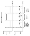
図2,図3は,試験差圧変化計測工程でのマスタ容器とワーク容器とを試験圧力で閉塞した状態で差圧の変化例を示す図である。図2にケース1,2が示され,図3にケース3〜6が示されている。各ケースでは,縦方向が圧力値または差圧値,横方向が時間に対応し,マスタ容器Mの内部圧力の変化と,ワーク容器の内部圧力の変化と,それらの差圧の変化dPとが示されている。
[Principle of differential pressure type leak test]
2 and 3 are diagrams showing examples of changes in the differential pressure in a state where the master container and the work container are closed with the test pressure in the test differential pressure change measurement process.
ケース1では,マスタ容器Mとワーク容器Wを試験圧力で閉塞した状態でいずれの内部圧力にも変化がない例である。この場合は差圧dPにも変化がない。したがって,ケース1ではワーク容器はリークなしと判断される。一方,ケース2では,マスタ容器Mもワーク容器Wも内部圧力が同じように増加した例である。このケース2は,例えばマスタ容器もワーク容器も外気温より温度が高く,試験中に両容器内の温度が上昇し,それによりマスタ容器とワーク容器の内部圧力が共に上昇した例であり,その結果差圧dPには変化はない。したがって,ケース2でもワーク容器はリークなしと判断される。ケース2において,例えばマスタ容器とワーク容器の温度が下降することで両者の内部圧力が同じ様に低下した場合も差圧dPには変化がなくワーク容器はリークなしと判断される。
このように,試験圧力での内部圧力の変化に差圧の変化を監視することで,マスタ容器とワーク容器に同じように外乱が影響しても,それらの影響を相殺することができる。つまり,マスタ容器とワーク容器の間で全ての条件が同じであれば,温度の変化による圧力変化は差圧には反映されず,正しくワーク容器のリークの有無を検出できる。さらに,試験圧力が例えば100kPaと高圧であっても,差圧の測定レンジは小さいので,差圧の変化を高い解像度で測定することができる。 In this way, by monitoring the change in the differential pressure with respect to the change in the internal pressure at the test pressure, even if the disturbance affects the master container and the work container in the same way, those effects can be offset. That is, if all conditions are the same between the master container and the work container, the pressure change due to the temperature change is not reflected in the differential pressure, and the presence or absence of the work container leak can be detected correctly. Furthermore, even if the test pressure is as high as 100 kPa, for example, since the measurement range of the differential pressure is small, the change in the differential pressure can be measured with high resolution.
図3のケース3では,マスタ容器Mの内部圧力に変化はないがワーク容器Wの内部圧力が低下し,それにより差圧dPが上昇した例である。ワーク容器Mの内部圧力の低下は,試験圧力が加圧状態でありワーク容器にリークが発生した場合である。このように差圧dPが上昇した場合はリーク有りと判定され不良品(+NG)と判定される。
一方,ケース4では,マスタ容器Mの内部圧力が低下しているがワーク容器Wの内部圧力は変化がなく,それにより差圧dPが下降した例である。マスタ容器の内部圧力のみが低下した原因は,例えば,マスタ容器の分岐配管2への装着が不完全でマスタ容器側にリークが発生した場合である。この場合も,適切に試験差圧変化計測を行うことができないので,不良品(−NG)と判定され,必要に応じて再試験が行われる。
On the other hand, in case 4, the internal pressure of the master container M is reduced, but the internal pressure of the work container W is not changed, and the differential pressure dP is thereby lowered. The reason why only the internal pressure of the master container is reduced is, for example, when the master container is not completely attached to the
しかしながら,図3のケース5では,ケース3と同様に,マスタ容器Mの内部圧力に変化はないがワーク容器Wの内部圧力が低下して,それにより差圧dPが上昇した例である。ただし,ワーク容器の内部圧力の低下は,例えばワーク容器が溶接工程直後の高温状態であり,試験圧力での試験差圧変化計測工程では温度低下情況にあることが原因である。この場合もワーク容器の内部圧力が低下するので,差圧dPが上昇する。この場合は,差圧dPの上昇によりリーク有りと判定され不良品(+NG)と判定される。しかし,ワーク容器にリークは発生しておらず,不良品とする判定は誤判定である。
However, in the
図3のケース6では,ケース4とは異なり,マスタ容器Mの内部圧力は変化ないがワーク容器Wの内部圧力は上昇し,差圧dPが低下した例である。ただし,ワーク容器の内部圧力の上昇は,例えば,ワーク容器が配管に装着されているマスタ容器よりも低温雰囲気の場所から持ってこられたため,試験圧力での試験差圧変化計測工程では温度上昇情況にあることが原因である。この場合は,差圧dPが低下して,不良品(−NG)と判定される。しかし,ワーク容器にリークは発生しておらず,不良品とする判定は誤判定である。
In the
図3のケース3と5を区別するために,またケース4と6を区別するために,本実施の形態のリーク試験では,温度補正計測モードを実行して,マスタ容器とワーク容器とを大気圧で閉塞した状態で差圧dPの変化を温度補正値として計測する温度補正値計測工程と,マスタ容器とワーク容器とを試験圧力で閉塞した状態で差圧dPの変化を試験差圧値として計測する試験差圧変化計測工程とを行い,試験差圧値を温度補正値に基づいて補正し,補正された試験差圧値に基づいてワーク容器のリークの有無を判断する。
In order to distinguish between
[温度補正計測モード]
以下,温度補正計測モードについて具体的に説明する。
[Temperature compensation measurement mode]
The temperature correction measurement mode will be specifically described below.
図4〜図7は,本実施の形態における差圧式のリーク試験での温度補正計測モードの例を示す図である。各図において,横軸が時間を,縦軸がマスタ容器及びワーク容器内の圧力Pと,差圧dPとを示す。 4 to 7 are diagrams showing examples of the temperature correction measurement mode in the differential pressure type leak test in the present embodiment. In each figure, the horizontal axis represents time, and the vertical axis represents the pressure P in the master container and the work container, and the differential pressure dP.
温度補正計測モードでは,マスタ容器とワーク容器とを試験圧力で閉塞した状態で差圧の変化を試験差圧値として計測する試験差圧変化計測工程S2と,その前後で若しくはその前後のいずれか一方で行う,マスタ容器とワーク容器とを大気圧で閉塞した状態で差圧dPの変化を温度補正値として計測する温度補正値計測工程S1,S2とが行われる。試験差圧変化計測工程S2の前に行う温度補正値計測工程S1を前工程,後に行う温度補正値計測工程S3を後工程と称する。 In the temperature correction measurement mode, a test differential pressure change measurement step S2 for measuring a change in differential pressure as a test differential pressure value in a state where the master container and the work container are closed with the test pressure, and either before or after the test differential pressure change measurement process S2. On the other hand, temperature correction value measurement steps S1 and S2 are performed, in which a change in the differential pressure dP is measured as a temperature correction value in a state where the master container and the work container are closed at atmospheric pressure. The temperature correction value measurement step S1 performed before the test differential pressure change measurement step S2 is referred to as a pre-process, and the temperature correction value measurement step S3 performed after the test differential pressure change measurement step S2 is referred to as a post-process.
工程S1終了後工程S2開始前において,バルブMV,WV,PVが開かれ圧力ポンプ5が駆動されマスタ容器とワーク容器が共に例えば100kPaの試験圧力に加圧され,そのマスタ容器側バルブMVとワーク容器側バルブWVが閉じられ試験圧力での閉塞状態にされる。また,工程S1開始前と,工程S2終了後工程S3開始前とにおいて,大気圧バルブAVとマスタ容器側バルブMVとワーク容器側バルブWVとが開かれ,加圧側バルブPVが閉じられ,マスタ容器とワーク容器が大気圧状態にされ,その後マスタ容器側バルブMVとワーク容器側バルブWVとが閉じられて大気圧で閉塞状態にされる。
After step S1 and before the start of step S2, the valves MV, WV, and PV are opened, the
さらに,温度補正計測モードでは,試験圧力での差圧変化である試験差圧値を,大気圧状態での差圧変化である温度補正値に基づいて補正し,補正された試験差圧値に基づいてワーク容器のリークの有無を判断する。補正された試験差圧値(試験圧力での差圧変化)が,ゼロつまり基準値を超えていなければ,ワーク容器にリークによる圧力変化はなかったと見なして,リークなしで良品と判定される。逆に,補正された試験差圧値が基準値を超えている場合は,ワーク容器にリークが発生したかマスタ容器の装着など何らかの不具合が発生したとして不良品と判定される。 Furthermore, in the temperature correction measurement mode, the test differential pressure value, which is the change in the differential pressure at the test pressure, is corrected based on the temperature correction value, which is the differential pressure change at atmospheric pressure, and the corrected test differential pressure value is obtained. Based on this, the presence or absence of leakage of the work container is determined. If the corrected test differential pressure value (differential pressure change at the test pressure) does not exceed zero, that is, the reference value, it is considered that there is no pressure change due to leak in the work container, and it is judged as a good product without leak. On the contrary, if the corrected test differential pressure value exceeds the reference value, it is determined that the work container is a defective product because a leak has occurred in the work container or some trouble has occurred such as mounting of the master container.
図4の例では,温度補正値計測工程S1,S3において差圧dPはゼロで変化していない。このことは,マスタ容器とワーク容器には温度変化の外乱はないことを意味している。同様に,試験差圧変化計測工程S2においても差圧dPはゼロで変化していない。したがって,この場合は,リーク試験中にマスタ容器もワーク容器も温度変化がなく,ワーク容器にリークが発生しておらず,良品(OK)と判定される。 In the example of FIG. 4, the differential pressure dP is zero and does not change in the temperature correction value measurement steps S1 and S3. This means that there is no disturbance of temperature change between the master container and the work container. Similarly, in the test differential pressure change measurement step S2, the differential pressure dP is zero and does not change. Therefore, in this case, there is no temperature change in the master container and the work container during the leak test, and no leak occurs in the work container, and it is determined that the product is OK (OK).
図5の例では,温度補正値計測工程S1,S3において差圧dPはゼロ(DP1=DP3=0)で変化していない。つまり,マスタ容器とワーク容器には温度変化の外乱はない。しかし,試験差圧変化計測工程S2において,差圧dPは上昇(DP2>0)している。差圧dPの上昇は,前述した図3のケース3,5と同じである。しかし,温度補正値計測工程S1,S3において差圧dPはゼロで変化していないので,ケース5ではなくケース3であることが判明する。リーク試験装置は,試験差圧変化計測工程S2での差圧の変化量DP2から,温度補正値計測工程S1またはS3での差圧の変化量DP1,DP3=0を除去して補正し,補正した差圧の変化量(DP2−DP1,DP2−DP3)が上昇していることに基づいて,リーク有りで不良品(+NG)と判定する。
In the example of FIG. 5, the differential pressure dP is zero (DP1 = DP3 = 0) and does not change in the temperature correction value measurement steps S1 and S3. That is, there is no disturbance of temperature change between the master container and the work container. However, the differential pressure dP increases (DP2> 0) in the test differential pressure change measurement step S2. The increase in the differential pressure dP is the same as in the
図6の例では,温度補正値計測工程S1,S3において差圧dPは共に上昇している(DP1=DP3>0)。例えば,ワーク容器の温度が上昇するなどの理由で差圧が上昇している。一方,試験差圧変化計測工程S2においても,差圧dPはDP2だけ上昇している。差圧の上昇量DP2は,前述した図3のケース3,5と同じである。ただし,この差圧dPの上昇DP2は,大気圧での差圧変化DP1,DP3と等しい。リーク試験装置は,試験差圧変化計測工程S2での差圧の変化量DP2から,温度補正値計測工程S1またはS3での差圧の変化量DP1=DP3(=DP2)を除去して補正し,補正した差圧の変化量(DP2−DP1,DP2−DP3)がゼロで基準値を超えていないことに基づいて,リークなしで良品(OK)と判定する。すなわち,ケース3ではなくケース5であることが判明する。
In the example of FIG. 6, the differential pressure dP increases in the temperature correction value measurement steps S1 and S3 (DP1 = DP3> 0). For example, the differential pressure is increased because the temperature of the work container is increased. On the other hand, also in the test differential pressure change measurement step S2, the differential pressure dP increases by DP2. The amount of increase DP2 in the differential pressure is the same as that of
図7の例では,温度補正値計測工程S1,S3において差圧dPは上昇している(DP1=DP3>0)。例えば,ワーク容器の温度が上昇するなどの理由である。一方,試験差圧変化計測工程S2においても,差圧dPはDP2だけ上昇している。ただし,この差圧の上昇量DP2は,大気圧での差圧変化DP1,DP3よりも大きい。リーク試験装置は,試験差圧変化計測工程S2での差圧の変化量DP2から,温度補正値計測工程S1またはS3での差圧の変化量DP1=DP3(<DP2)を除去して補正し,補正した差圧の変化量(DP2−DP1>0,DP2−DP3>0)が依然としてゼロでなく,所定の基準値を超えていることに基づいて,リーク有りで不良品(+NG)と判定する。 In the example of FIG. 7, the differential pressure dP increases in the temperature correction value measurement steps S1 and S3 (DP1 = DP3> 0). For example, the temperature of the work container increases. On the other hand, also in the test differential pressure change measurement step S2, the differential pressure dP increases by DP2. However, the increase amount DP2 of the differential pressure is larger than the differential pressure changes DP1 and DP3 at atmospheric pressure. The leak test apparatus corrects the differential pressure change amount DP2 in the test differential pressure change measurement step S2 by removing the differential pressure change amount DP1 = DP3 (<DP2) in the temperature correction value measurement step S1 or S3. Based on the fact that the corrected differential pressure variation (DP2-DP1> 0, DP2-DP3> 0) is still not zero and exceeds a predetermined reference value, it is determined that there is a leak (+ NG). To do.
上記の図4〜7において,リーク試験中S1,S2,S3に,ワーク容器の温度上昇などにより差圧dPが低下するような場合も,同様にして,その温度変化による外乱の影響を除去してワーク容器のリークの有無を判定することができる。 4 to 7, in the case where the differential pressure dP decreases due to the temperature rise of the work container during S1, S2, and S3 during the leak test, the influence of disturbance due to the temperature change is similarly removed. Thus, it is possible to determine whether or not there is a leak in the work container.
[温度補正演算]
前述のとおり,温度補正計測モードでは,試験圧力での差圧変化である試験差圧値DP2を,大気圧での差圧変化である温度補正値DP1またはDP3に基づいて補正し,補正された試験差圧値DP2−DP1(またはDP2−DP3)に基づいてワーク容器のリークの有無を判断する。ただし,大気圧状態と試験圧力状態とでは,マスタ容器やワーク容器内の気体の密度が異なる。そこで,本実施の形態では,この気体密度の違いも考慮して,大気圧状態での差圧変化量(試験差圧値)か,試験圧力状態での差圧変化量(温度補正値)かのいずれかを気体密度の違いに応じて補正して,試験差圧値から温度補正値を減算する。
[Temperature compensation calculation]
As described above, in the temperature correction measurement mode, the test differential pressure value DP2 that is a change in the differential pressure at the test pressure is corrected based on the temperature correction value DP1 or DP3 that is the differential pressure change at the atmospheric pressure. Based on the test differential pressure value DP2-DP1 (or DP2-DP3), the presence / absence of leakage of the work container is determined. However, the density of the gas in the master container and the work container differs between the atmospheric pressure state and the test pressure state. Therefore, in the present embodiment, considering the difference in gas density, whether the differential pressure change amount in the atmospheric pressure state (test differential pressure value) or the differential pressure change amount in the test pressure state (temperature correction value) is used. Either of the above is corrected according to the difference in gas density, and the temperature correction value is subtracted from the test differential pressure value.
理想気体の状態方程式は,以下の通りである。
PV=ρRθ (1)
ここで,P:圧力(Pa),V:容器の容積(m3),ρ:空気の密度(Kg/m3),R:ガス定数(J/(Kg.K),θ:温度(K)である。この状態方程式(1)から圧力は,以下の通りである。
P=ρRθ/V
そして,試験圧力状態での差圧変化量(試験差圧値)をDP2=ρ2Rθ/V,大気圧状態での差圧変化量(温度補正値)をDP1=ρ1Rθ/Vとすれば,補正された差圧変化量(補正試験差圧値)は,以下の通りである。
DP2−DP1=ρ2Rθ/V−ρ1Rθ/V (2)
上記の式(2)から,試験圧力(例えば100kPa(G))での気体密度ρ2と,大気圧(0kPa(G),101.325kPa(Abs))での気体密度ρ1との比,ρ2/ρ1が大気圧状態の差圧変化量(温度補正値)に対する補正係数であり,1.986≒1.99である。従って,式(2)は次の通りである。
DP2−1.99×DP1=ρ2Rθ/V−1.99×ρ1Rθ/V (2A)
[温度補正値計測モードと圧力計測モード]
図8は,本実施の形態における温度補正計測モードを示す図である。図4〜図7と同様に,マスタ容器とワーク容器を試験圧力状態で差圧の変化(試験差圧値)を計測する試験差圧変化計測工程S2と,その前後に行う大気圧状態で差圧の変化(温度補正値)を計測する温度補正値計測工程S1,S3とを有する。温度補正値計測工程S1,S3は,いずれか一方のみを行っても良いが,2回行う場合はその平均値を温度補正値にしてもよい。
The equation of state of the ideal gas is as follows.
PV = ρRθ (1)
Where P: pressure (Pa), V: volume of container (m 3 ), ρ: density of air (Kg / m 3 ), R: gas constant (J / (Kg.K), θ: temperature (K) From this state equation (1), the pressure is as follows.
P = ρRθ / V
The differential pressure change amount (test differential pressure value) in the test pressure state is DP2 = ρ 2 Rθ / V, and the differential pressure change amount (temperature correction value) in the atmospheric pressure state is DP1 = ρ 1 Rθ / V. For example, the corrected differential pressure variation (corrected test differential pressure value) is as follows.
DP2−DP1 = ρ 2 Rθ / V−ρ 1 Rθ / V (2)
The ratio of the above equation (2), the gas density [rho 2 of the test pressure (e.g. 100 kPa (G)), the gas density [rho 1 at atmospheric pressure (0 kPa (G), 101.325 kPa (Abs)), [rho 2 / [rho 1 is a correction coefficient for the difference pressure variation of atmospheric pressure (temperature correction value) is 1.986 ≒ 1.99. Therefore, Formula (2) is as follows.
DP2-1.99 × DP1 = ρ 2 Rθ / V−1.99 × ρ 1 Rθ / V (2A)
[Temperature compensation value measurement mode and pressure measurement mode]
FIG. 8 is a diagram showing a temperature correction measurement mode in the present embodiment. Similar to FIGS. 4 to 7, the test differential pressure change measurement step S <b> 2 for measuring the change in the differential pressure (test differential pressure value) between the master container and the work container in the test pressure state, and the atmospheric pressure state before and after the difference. Temperature correction value measuring steps S1 and S3 for measuring a change in pressure (temperature correction value). Only one of the temperature correction value measurement steps S1 and S3 may be performed. However, when the temperature correction value measurement steps S1 and S3 are performed twice, the average value may be used as the temperature correction value.
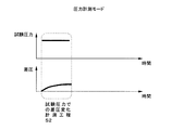
図9は,本実施の形態における圧力計測モードを示す図である。圧力計測モードでは,温度補正値計測工程S1,S3を行わずに,試験差圧変化計測工程S2のみを行う。したがって,圧力計測モードは,温度補正値計測工程で差圧変化がゼロ,具体的には所定の基準値を超えないような場合に実施可能であり,試験差圧値を温度補正値で補正せず,試験差圧値が変化したか否か,つまり所定の基準値を超えたか否かに応じて,試験フェイル(不良品,+NG,−NG)か,試験パス(良品,OK)と判断する。そして,圧力計測モードにおいて試験フェイル(+NG,−NG)の場合は,温度変化による圧力変化の可能性があるので,再度温度補正計測モードを実行して温度補正した試験差圧値でリークの有無を判定する。 FIG. 9 is a diagram showing a pressure measurement mode in the present embodiment. In the pressure measurement mode, only the test differential pressure change measurement step S2 is performed without performing the temperature correction value measurement steps S1 and S3. Therefore, the pressure measurement mode can be implemented when the differential pressure change is zero in the temperature correction value measurement process, specifically when it does not exceed a predetermined reference value, and the test differential pressure value is corrected with the temperature correction value. First, depending on whether or not the test differential pressure value has changed, that is, whether or not a predetermined reference value has been exceeded, it is determined that the test has failed (defective product, + NG, -NG) or test pass (good product, OK). . In the case of a test failure (+ NG, -NG) in the pressure measurement mode, there is a possibility of a pressure change due to a temperature change. Therefore, whether or not there is a leak with the test differential pressure value corrected by performing the temperature correction measurement mode again. Determine.
[第1の実施の形態]
図10は,第1の実施の形態におけるリーク試験での温度補正計測モードS11と圧力計測モードS14の状態遷移図である。図11は,そのリーク試験の一例を示す図である。図11を参照しながら図10のリーク試験について説明する。
[First Embodiment]
FIG. 10 is a state transition diagram of the temperature correction measurement mode S11 and the pressure measurement mode S14 in the leak test according to the first embodiment. FIG. 11 is a diagram showing an example of the leak test. The leak test of FIG. 10 will be described with reference to FIG.
複数のワーク容器のリーク試験工程において,試験開始時S10では,温度補正計測モードS11でワーク容器のリーク試験を行う。つまり,図8に示したとおり,大気圧状態での温度補正値計測工程S1,S3と,試験圧力状態での試験差圧変化計測工程S2とを行い,試験圧力での差圧変化を温度補正値で補正する。この温度補正計測モードS11での大気圧状態での温度補正値計測工程S1,S3で差圧変化が発生してゼロでない場合,つまり差圧変化が所定の基準値を超える場合は(S12),温度変化による差圧変化が発生していて温度補正が必要であるので,次のワーク容器に対するリーク試験も,図8の温度補正計測モードS11で繰り返す。このS12の大気圧状態での差圧変化ありとは,前述の図6,7のような場合である。 In the leak test process for a plurality of work containers, at a test start time S10, a work container leak test is performed in the temperature correction measurement mode S11. That is, as shown in FIG. 8, the temperature correction value measurement steps S1 and S3 in the atmospheric pressure state and the test differential pressure change measurement step S2 in the test pressure state are performed, and the differential pressure change at the test pressure is temperature corrected. Correct by value. When the differential pressure change occurs in the temperature correction value measurement steps S1 and S3 in the atmospheric pressure state in the temperature correction measurement mode S11 and is not zero, that is, when the differential pressure change exceeds a predetermined reference value (S12), Since the differential pressure change due to the temperature change has occurred and temperature correction is required, the leak test for the next workpiece container is repeated in the temperature correction measurement mode S11 of FIG. The change in the differential pressure in the atmospheric pressure state in S12 is the case as shown in FIGS.
一方,温度補正計測モードでの大気圧状態での温度補正値計測工程S1,S3で差圧変化がゼロ,つまり所定の基準値を超えない場合は(S13),温度変化による差圧変化は発生していないと見なして,次のワーク容器に対するリーク試験からは,図9の圧力計測モードS14で行う。このS13の大気圧状態での差圧変化なしとは,前述の図4,5のような場合である。そして,圧力計測モードS14でのリーク試験結果が良品(OK)の判定であれば,その圧力測定モードS14でのリーク試験を繰り返して行う。圧力計測モードS14では大気圧状態で差圧変化を測定する温度補正値計測工程S1,S3を省略できるのでリーク試験時間を短縮できる。 On the other hand, if the differential pressure change is zero in the temperature correction value measurement steps S1 and S3 in the atmospheric pressure state in the temperature correction measurement mode, that is, if the predetermined reference value is not exceeded (S13), the differential pressure change due to the temperature change occurs. 9 is performed in the pressure measurement mode S14 of FIG. 9 from the leak test for the next work container. The fact that there is no differential pressure change in the atmospheric pressure state in S13 is the case as shown in FIGS. If the leak test result in the pressure measurement mode S14 is a non-defective product (OK) determination, the leak test in the pressure measurement mode S14 is repeated. In the pressure measurement mode S14, the temperature correction value measurement steps S1 and S3 for measuring the differential pressure change in the atmospheric pressure state can be omitted, so that the leak test time can be shortened.
圧力計測モードS14では,大気圧状態での温度補正値計測工程S1,S3を省略し,試験圧力状態で差圧変化を測定する試験差圧変化計測工程S2で得た差圧変化の有無により,リーク有無の判定を行う。このリーク判定では,先に計測した温度補正値(差圧変化ゼロではあるが)に基づいて試験圧力状態での差圧変化を補正して判定したと見なすこともできる。そして,このリーク判定では,次の4つの状態を判定することができる。すなわち,第1に,試験圧力状態で差圧変化がなければ,温度変化の影響もないとの仮定により,ワーク容器は良品(OK)と判定される。第2〜第4に,試験圧力状態で差圧変化が生じた場合は,図5,6,7で説明したとおり,温度変化の影響はなくワーク容器にリークが発生した場合(図5の場合)と,ワーク容器にリークは生じていないが温度変化の影響が発生している場合(図6の場合)と,さらに,温度変化の影響が発生し且つワーク容器にリークが発生した場合(図7の場合)である。 In the pressure measurement mode S14, the temperature correction value measurement steps S1 and S3 in the atmospheric pressure state are omitted, and the presence or absence of the differential pressure change obtained in the test differential pressure change measurement step S2 in which the differential pressure change is measured in the test pressure state. Determine whether there is a leak. In this leak determination, it can also be considered that the determination is made by correcting the differential pressure change in the test pressure state based on the temperature correction value measured earlier (although the differential pressure change is zero). In this leak determination, the following four states can be determined. That is, first, if there is no change in the differential pressure in the test pressure state, the work container is determined to be a non-defective product (OK) on the assumption that there is no influence of temperature change. Second to fourth, when a differential pressure change occurs in the test pressure state, as described in FIGS. 5, 6, and 7, there is no effect of temperature change and a leak occurs in the work container (in the case of FIG. 5). ), When there is no leak in the work container but there is an effect of temperature change (in the case of FIG. 6), and when there is an effect of temperature change and there is a leak in the work container (see FIG. 6). 7).
したがって,圧力計測モードS14において,良品(OK)判定が出ている間は(S15),上記の第1の状態であるので圧力計測モードS14を繰り返し実施する。しかし,不良品(+NG,−NG)判定が出た場合は(S16),上記の第2〜第4のいずれかであることを確認する必要があるので,そのワーク容器については温度補正計測モードS11で再度リーク試験を行う。温度補正計測モードS11によれば,図5,6,7の3つの状態を区別することができ,適切に良品と不良品を区別することができる。 Therefore, in the pressure measurement mode S14, while the non-defective product (OK) determination is made (S15), the pressure measurement mode S14 is repeatedly performed because the first state is described above. However, if a defective product (+ NG, -NG) determination is made (S16), it is necessary to confirm that it is one of the above-mentioned second to fourth. In S11, the leak test is performed again. According to the temperature correction measurement mode S11, the three states of FIGS. 5, 6, and 7 can be distinguished, and a good product and a defective product can be appropriately distinguished.
前述の通り,温度補正計測モードS11で大気圧状態での差圧変化があれば(S12),次のワーク容器についてもその温度補正計測モードS11を繰り返すが,大気圧状態での差圧変化がなければ(S13),圧力測定モードS14に移行する。 As described above, if there is a differential pressure change in the atmospheric pressure state in the temperature correction measurement mode S11 (S12), the temperature correction measurement mode S11 is repeated for the next workpiece container, but the differential pressure change in the atmospheric pressure state is repeated. If not (S13), the process proceeds to the pressure measurement mode S14.
図11に図10の状態遷移が適用された例が示されている。図11中の(1)温度補正計測モードで大気圧状態で差圧変化がゼロの場合には,(2)圧力計測モードに移行する。そして,図11(2)の圧力計測モードで,試験圧力状態で差圧変化が発生して不良品(+NG)の判定が出た場合は,図11(3A)(3B)の温度補正計測モードに移行する。(3A)は図6と同じであり,温度補正した試験圧力の差圧変化がゼロで良品(OK)と判定された例である。また,(3B)は図5,7と同じであり,温度補正した試験圧力での差圧変化がゼロではなく不良品(+NG)と判定された例である。 FIG. 11 shows an example in which the state transition of FIG. 10 is applied. When (1) temperature correction measurement mode in FIG. 11 is zero and the differential pressure change is zero in the atmospheric pressure state, (2) transition to pressure measurement mode. In the pressure measurement mode of FIG. 11 (2), when a change in the differential pressure occurs in the test pressure state and a defective product (+ NG) is determined, the temperature correction measurement mode of FIGS. 11 (3A) and (3B). Migrate to (3A) is the same as FIG. 6, and is an example in which the change in the differential pressure of the test pressure subjected to temperature correction is zero and the product is determined to be non-defective (OK). Further, (3B) is the same as FIGS. 5 and 7, and is an example in which the change in the differential pressure at the temperature-corrected test pressure is determined to be defective (+ NG) instead of zero.
上記の通り,本実施の形態におけるリーク試験では,大気圧状態での差圧変化がゼロの場合に温度補正値計測工程を省略する圧力計測モードS14に移行し,試験圧力状態での差圧変化がゼロで良品(OK)判定がされている間は,圧力計測モードS14を繰り返し実施する。これにより,リーク試験の誤判定をなくしつつ,リーク試験時間を短縮している。 As described above, in the leak test in the present embodiment, when the differential pressure change in the atmospheric pressure state is zero, the process proceeds to the pressure measurement mode S14 in which the temperature correction value measurement process is omitted, and the differential pressure change in the test pressure state. Is zero and the non-defective product (OK) determination is made, the pressure measurement mode S14 is repeated. As a result, the leak test time is shortened while eliminating the erroneous determination of the leak test.
図12は,リーク試験で誤判定が発生する例を示す図である。図12(1)は温度補正計測モードで大気圧状態での温度補正値計測工程S1,S3で差圧変化DP1,DP3が発生している。しかし,この温度補正値計測工程での差圧変化DP1,DP3が同じ値を繰り返した場合は,温度変化が安定して繰り返されていると仮定して,温度補正値計測工程を省略する圧力測定モードに移行することが考えられる。図12(2)の圧力測定モードでは,温度補正値計測工程S1,S3が省略され,図12(1)の温度補正計測モードで求めた温度補正値DP1,DP3を利用して温度補正が行われる。図12(2)の例では(1)と同様の試験圧力状態で差圧変化DP2が発生し,(1)で求めた温度補正値DP1,PD3を減算することでDP2−DP1(またはDP3)=0が得られ,試験圧力状態でのリークによる差圧変化はなしと判定され,良品(OK)判定される。 FIG. 12 is a diagram illustrating an example in which an erroneous determination occurs in the leak test. FIG. 12 (1) shows the differential pressure changes DP1 and DP3 in the temperature correction value measurement steps S1 and S3 in the atmospheric pressure state in the temperature correction measurement mode. However, when the differential pressure changes DP1 and DP3 in the temperature correction value measurement process repeat the same value, it is assumed that the temperature change is stably repeated, and the pressure correction measurement process is omitted. It can be considered to shift to the mode. In the pressure measurement mode of FIG. 12 (2), the temperature correction value measurement steps S1 and S3 are omitted, and temperature correction is performed using the temperature correction values DP1 and DP3 obtained in the temperature correction measurement mode of FIG. 12 (1). Is called. In the example of FIG. 12 (2), a differential pressure change DP2 occurs in the same test pressure state as in (1), and DP2-DP1 (or DP3) is obtained by subtracting the temperature correction values DP1 and PD3 obtained in (1). = 0 is obtained, it is determined that there is no change in the differential pressure due to leakage in the test pressure state, and a non-defective product (OK) is determined.
ところが,図12の(2)の圧力計測モードは,実は,図12の(2A)(2B)の2つの状態がありうる。すなわち,(2A)では(1)と同様にDP2=DP1,DP3であり,良品判定は正しい判定である。一方,(2B)では(1)と異なり大気圧状態で求めた温度補正値DP1,DP2が,ゼロまたは(1)のDP1,DP3より小さい場合である。この場合は,温度補正後の値DP2―DP1(またはDP3)>0となり,不良品(+NG)判定されるべきである。したがって,図12の(2)での良品(OK)判定は誤判定であることが理解できる。 However, the pressure measurement mode (2) in FIG. 12 may actually have two states (2A) and (2B) in FIG. That is, in (2A), DP2 = DP1 and DP3 as in (1), and the non-defective product determination is correct. On the other hand, in (2B), unlike (1), the temperature correction values DP1 and DP2 obtained in the atmospheric pressure state are zero or smaller than DP1 and DP3 in (1). In this case, the value DP2-DP1 (or DP3) after temperature correction is> 0, and a defective product (+ NG) should be determined. Therefore, it can be understood that the non-defective product (OK) determination in (2) of FIG. 12 is an erroneous determination.
このように,単に温度補正値計測工程で検出した差圧変化DP1,DP3が安定して繰り返されていることを理由に,その工程を省略した圧力測定モードに移行すると,誤判定になる可能性があり好ましくない。 As described above, if the pressure measurement mode without the process is shifted to the pressure measurement mode simply because the differential pressure changes DP1 and DP3 detected in the temperature correction value measurement process are stably repeated, there is a possibility of erroneous determination. Is not preferable.
それに対して,本実施の形態での図10,図11のリーク試験方法では,図12に示したような誤判定を招くことはない。つまり,本実施の形態によれば,誤判定を回避しつつリーク試験時間を短縮することができる。 On the other hand, the leak test method of FIGS. 10 and 11 in the present embodiment does not cause an erroneous determination as shown in FIG. That is, according to the present embodiment, it is possible to shorten the leak test time while avoiding erroneous determination.
図1に示したリーク試験装置は,図10に示された状態遷移によりリーク試験を行う。図10の状態遷移は既に説明したとおりであるが,上記の説明に加えて,圧力計測モード工程S14を予め決めた回数であるn回繰り返した場合は,強制的に温度補正計測モードS11に移行し,改めて温度補正値計測工程をおこなって大気圧状態での差圧変化がゼロであることを確認する。または,圧力計測モード工程S14を繰り返している途中で,昼休みなど所定時間リーク試験を中断した場合も,温度補正計測モードS11に移行することが望ましい。時間の経過に伴い,温度変化による差圧変化が発生している蓋然性が高くなるからである。 The leak test apparatus shown in FIG. 1 performs a leak test based on the state transition shown in FIG. The state transition of FIG. 10 is as described above. In addition to the above description, when the pressure measurement mode step S14 is repeated n times that is a predetermined number of times, the state is forcibly shifted to the temperature correction measurement mode S11. Then, the temperature correction value measurement process is performed again to confirm that the differential pressure change at atmospheric pressure is zero. Alternatively, when the leak test is interrupted for a predetermined time such as a lunch break while the pressure measurement mode process S14 is being repeated, it is desirable to shift to the temperature correction measurement mode S11. This is because the probability that a differential pressure change due to a temperature change occurs with the passage of time increases.
[リーク試験装置の動作]
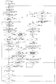
図13は,本実施の形態におけるリーク試験装置の動作フローチャート図である。ここに示したリーク試験装置の試験動作では,温度補正計測モードにおいて,原則として前工程の温度補正値計測工程S1で求めた温度補正値を使って試験差圧変化計測工程で求めた試験差圧値を補正してリーク判定を行う。リーク判定が良品(OK)であれば,後工程の温度補正値計測工程S3は行わない。一方,リーク判定が不良(+NG,-NG)であれば,後工程の温度補正値計測工程S3を実施して前工程と後工程の温度補正値の平均値で試験差圧値を補正してリーク判定を行う。
[Operation of leak test equipment]
FIG. 13 is an operation flowchart of the leak test apparatus in the present embodiment. In the test operation of the leak test equipment shown here, in the temperature compensation measurement mode, as a rule, the test differential pressure obtained in the test differential pressure change measurement process using the temperature compensation value obtained in the temperature compensation value measurement process S1 of the previous process. The leak is judged by correcting the value. If the leak determination is a non-defective product (OK), the temperature correction value measurement step S3 in the subsequent process is not performed. On the other hand, if the leak judgment is poor (+ NG, -NG), the temperature correction value measurement step S3 in the subsequent process is performed, and the test differential pressure value is corrected with the average value of the temperature correction values in the previous process and the subsequent process. Perform leak judgment.
さらに,圧力計測モードでは,試験差圧変化計測工程S2で求めた試験差圧値によりリーク判定を行い,そのリーク判定が不良(+NG,-NG)であれば,温度補正値計測工程を行い,そこで求めた温度補正値を使って試験差圧値を補正して再度リーク判定を行う。つまり,圧力計測モードでの試験差圧変化計測工程S2とその次の温度補正値計測工程とにより温度補正計測モード工程を実施する。 Furthermore, in the pressure measurement mode, a leak judgment is performed based on the test differential pressure value obtained in the test differential pressure change measurement step S2, and if the leak judgment is poor (+ NG, -NG), a temperature correction value measurement step is performed, Accordingly, the test differential pressure value is corrected using the obtained temperature correction value, and the leak determination is performed again. That is, the temperature correction measurement mode process is performed by the test differential pressure change measurement process S2 in the pressure measurement mode and the subsequent temperature correction value measurement process.
図13を参照して,リーク試験装置の動作について説明する。スタートボタンがオンされるとリーク試験が開始されて,変数N,Y,Zが初期値0にリセットされる(S20)。変数Nは圧力計測モードの連続回数,変数Yは後述する変形例で使用されるリトライ回数,変数Zは温度補正計測モード(Z=1)と圧力計測モード(Z=0)を示すフラグである。工程S21でも変数Z,Nが初期値0にリセットされる。
The operation of the leak test apparatus will be described with reference to FIG. When the start button is turned on, the leak test is started and the variables N, Y, and Z are reset to the initial value 0 (S20). Variable N is the number of consecutive pressure measurement modes, variable Y is the number of retries used in a later-described modification, and variable Z is a flag indicating temperature correction measurement mode (Z = 1) and pressure measurement mode (Z = 0) . In step S21, the variables Z and N are reset to the
そして,前工程の温度補正値計測工程S1を開始する(S22)。すなわち,一旦,図1に示したバルブMV,WVと減圧用バルブAVを開き,供給用バルブPVを閉じて,マスタ容器とワーク容器とを大気圧状態にし(S23),その後開いたバルブMV,WV,AVを閉じる(S24)。これで両容器は大気圧で閉塞される。そして,差圧センサが計測する差圧に変化がないか否かを判定する(S25)。差圧に変化があれば,温度補正計測モードに設定するためにフラグZをZ=1にする(S26)。差圧に変化がなければフラグZは初期値のZ=0であり圧力計測モードである。 Then, the temperature correction value measurement step S1 of the previous step is started (S22). That is, once the valves MV, WV and the pressure reducing valve AV shown in FIG. 1 are opened, the supply valve PV is closed, the master container and the work container are brought to atmospheric pressure (S23), and then the opened valves MV, Close WV and AV (S24). Both containers are now closed at atmospheric pressure. Then, it is determined whether there is no change in the differential pressure measured by the differential pressure sensor (S25). If there is a change in the differential pressure, the flag Z is set to Z = 1 to set the temperature correction measurement mode (S26). If there is no change in the differential pressure, the flag Z is the initial value Z = 0 and the pressure measurement mode is set.
上記の大気圧状態での差圧に変化がなければ,圧力計測モード(Z=0)になり,回数NをN+1にする(S27)。そして,加圧状態での差圧計測(試験差圧計測工程S2)を開始する(S28)。つまり,バルブMV,WV,PVを開いて圧力ポンプ5から加圧する(S29)。この時,図1のワーク側配管3に取り付けられた単圧センサ(図示せず)の圧力値をフィードバックしてワーク容器内圧力が所望の圧力になるようにする。所望の圧力なると,バルブMV,WVを閉じて両容器を閉塞する(S30)。そして,この加圧状態での差圧の変化を測定し,Z=0の場合は(S31のNO),その差圧変化があるか否かでリークの有無を判定する(S34)。Z=1の場合は温度補正計測モードであるので,温度補正値を使って補正した差圧変化に基づいてリークの有無を判定する(S32)。
If there is no change in the differential pressure in the atmospheric pressure state, the pressure measurement mode (Z = 0) is entered, and the number of times N is set to N + 1 (S27). Then, differential pressure measurement in the pressurized state (test differential pressure measurement step S2) is started (S28). That is, the valves MV, WV, and PV are opened and pressurized from the pressure pump 5 (S29). At this time, the pressure value of a single pressure sensor (not shown) attached to the
今は,仮に圧力測定モード(Z=0)であるとする。したがって,加圧状態での差圧変化によりリーク判定を行い(S34),リークなしであれば,供給用バルブPVを閉じて(S35),バルブMV,WV,AVを開いてマスタ容器とワーク容器とを大気圧に解放する(S36)。そして,リーク試験装置は,合格ランプを点灯し(S37),ワーク交換指示を出力する(S38)。作業者がワーク容器を交換してスタートスイッチをオンにすると(S39),次のワーク容器に対するリーク試験が開始される。工程S40でのX=0,Y=0は後述する変形例に対するものである。また,工程S41では圧力計測モードの回数Nが所定値n(例えば10回)に達していないかを確認し,達していなければ、工程S42でZ=0の確認を経て,工程S27に戻る。 Now assume that the pressure measurement mode (Z = 0). Therefore, a leak judgment is made based on the differential pressure change in the pressurized state (S34). If there is no leak, the supply valve PV is closed (S35), the valves MV, WV, AV are opened, and the master container and work container Are released to atmospheric pressure (S36). Then, the leak test apparatus turns on the pass lamp (S37) and outputs a workpiece replacement instruction (S38). When the operator replaces the work container and turns on the start switch (S39), the leak test for the next work container is started. X = 0, Y = 0 in the step S40 is for a modified example to be described later. In step S41, it is confirmed whether the number N of pressure measurement modes has reached a predetermined value n (for example, 10 times). If not, Z = 0 is confirmed in step S42, and the process returns to step S27.
次の,ワーク容器に対しても,工程S27からS31までと,S34からS38までの圧力計測モードを行い,リーク判定がリークなし(良品OK)である限りは,回数Nがn=10に達するまでか,途中で所定時間の試験中断が発生するまで(S55,S56でワーク容器交換の時間を計測する交換タイマがタイムオーバになるまで),その圧力計測モードを繰り返す。工程S56で回数Nが10回に達した場合や試験中断した場合は,工程S21に戻り,再度温度補正値計測工程S22を実行する。中断によるタイムオーバ後は,スタートスイッチがオンになると(S57),リーク試験は再開される。 For the next work container, the pressure measurement mode from steps S27 to S31 and S34 to S38 is performed, and the number of times N reaches n = 10 as long as the leak judgment is no leak (good product OK). Until the test is interrupted for a predetermined time in the middle (until the replacement timer for measuring the time for replacing the work container in S55 and S56 is over), the pressure measurement mode is repeated. When the number N reaches 10 in step S56 or when the test is interrupted, the process returns to step S21, and the temperature correction value measurement step S22 is executed again. After the time-out due to interruption, the leak test is resumed when the start switch is turned on (S57).
圧力計測モードから温度補正計測モードに遷移するもう一つの条件は,工程S34でのリーク判定でリークあり(+NG,-NG)(S43)となったときである。この場合は,温度補正値計測工程(S44)を開始し,バルブMV,WV,AVを開きバルブPVを閉じてマスタ容器とワーク容器を大気圧に解放し(S45),その後バルブMV,WV,AVを閉じて閉塞状態にする(S46)。そして,大気圧状態での差圧の変化を温度補正値として検出し,Z=0であるので工程S47ではNOに分岐し,今回の温度補正値を使って試験圧力状態での差圧変化を補正して,リークの有無を判定する(S52)。ここでリークあり(不良品)と判定されたら,リーク試験装置は不良ランプを点灯し(S49),供給用バルブPVを閉じ,他のバルブMV,WV,AVを開いて(S50),マスタ容器とワーク容器を大気圧に解放し,ワーク交換指示を出力する(S38)。なお,工程S51でZ=1にして温度補正計測モードに変更する。 Another condition for transitioning from the pressure measurement mode to the temperature correction measurement mode is when there is a leak (+ NG, −NG) (S43) in the leak determination in step S34. In this case, the temperature correction value measurement step (S44) is started, the valves MV, WV, AV are opened, the valve PV is closed, the master container and the work container are released to atmospheric pressure (S45), and then the valves MV, WV, The AV is closed and closed (S46). Then, the change in the differential pressure in the atmospheric pressure state is detected as a temperature correction value. Since Z = 0, the process branches to NO in step S47, and the change in the differential pressure in the test pressure state is detected using the current temperature correction value. Correction is made to determine whether or not there is a leak (S52). If it is determined that there is a leak (defective product), the leak tester turns on the defective lamp (S49), closes the supply valve PV, opens the other valves MV, WV, AV (S50), and the master container. And the work container is released to atmospheric pressure, and a work replacement instruction is output (S38). In step S51, Z = 1 is set to change to the temperature correction measurement mode.
次に,温度補正計測モード(Z=0)での試験動作について説明する。前工程の温度補正値計測工程S22-S25を行い,試験差圧変化計測工程S28-S30を行い,温度補正値を使って補正した加圧状態での差圧変化に基づいてリーク判定を行う(S32)。リークなしであれば(S32のYES),合格ランプを点灯し(S37),ワーク交換を指示する(S38)。 Next, the test operation in the temperature correction measurement mode (Z = 0) will be described. Perform the temperature correction value measurement process S22-S25 of the previous process, perform the test differential pressure change measurement process S28-S30, and perform leak determination based on the differential pressure change in the pressurized state corrected using the temperature correction value ( S32). If there is no leak (YES in S32), the pass lamp is turned on (S37), and the work replacement is instructed (S38).
リークありであれば(S32のNO),後工程の温度補正値計測工程S44-S46を行い,前工程と後工程での温度補正値の平均値で補正した加圧状態での差圧変化に基づいてリーク判定を行う(S48)。判定がリークあり(不良品)であれば,不良ランプを点灯し(S49),マスタ容器とワーク容器を大気圧状態に解放する(S50)。判定がリークなし(良品)であれば,マスタ容器とワーク容器を大気圧状態に解放し(S53),合格ランプを点灯する(S54)。そして,ワーク交換を指示して(S38),ワーク容器交換後のスタートスイッチオンを待つ(S39)。 If there is a leak (NO in S32), perform the temperature correction value measurement process S44-S46 in the subsequent process, and change the pressure difference in the pressurized state corrected by the average value of the temperature correction value in the previous process and the subsequent process. Based on this, a leak determination is made (S48). If there is a leak (defective product), the defective lamp is turned on (S49), and the master container and the work container are released to atmospheric pressure (S50). If there is no leak (non-defective), the master container and the work container are released to atmospheric pressure (S53), and the acceptance lamp is turned on (S54). Then, the workpiece replacement is instructed (S38), and the start switch on after the workpiece container replacement is waited (S39).
[リーク試験装置の動作の変形例1]
図14は,本実施の形態におけるリーク試験装置の動作の変形例1のフローチャート図である。このリーク試験装置の動作では,工程S60-S67が図13に追加されている。この工程S60-S67では,加圧計測モード中にリーク判定でリーク有り(不良+NG,-NG)となった場合(S34でNO),即座に温度補正計測モードに遷移するのではなく,所定回数yを繰り返し回数の上限として圧力計測モードを繰り返し,リークなしと判定されないか確認する。すなわち,大気圧への解放(S63,S64)後,試験圧力への加圧(S28-S30)と加圧状態での差圧変化に基づくリーク判定(S32)とからなる試験差圧変化計測工程を,繰り返し回数Y=yを上限として,リークなし(良品OK)になるまで繰り返す。ただし,所定回数yまでの繰り返し中に,回数Xが所定回数x(x<y)に達すると(S65のYES),冷却ファンをオンにし(S66),冷却ファンでマスタ容器とワーク容器とを冷却しながら,試験差圧変化計測工程(S28-S30,S32)を,繰り返し回数Y=yを上限として,リークなし(良品OK)の判定まで繰り返す。そして,そのワークの試験が終了すると冷却ファンをオフにする(S67)。
[First Modification of Operation of Leak Test Apparatus]
FIG. 14 is a flowchart of Modification Example 1 of the operation of the leak test apparatus in the present embodiment. In the operation of the leak test apparatus, steps S60 to S67 are added to FIG. In this process S60-S67, if there is a leak (defect + NG, -NG) during the pressure measurement mode (NO in S34), it does not immediately switch to the temperature correction measurement mode, Repeat the pressure measurement mode with the number of times y as the upper limit of the number of repetitions, and check if there is no leak. That is, after the release to atmospheric pressure (S63, S64), the test differential pressure change measurement process consisting of pressurization to the test pressure (S28-S30) and leak judgment based on the differential pressure change in the pressurized state (S32) Repeat until the number of repetitions Y = y is the upper limit until there is no leak (good product OK). However, if the number X reaches the predetermined number x (x <y) during the repetition up to the predetermined number y (YES in S65), the cooling fan is turned on (S66), and the master container and work container are connected with the cooling fan. While cooling, repeat the test differential pressure change measurement process (S28-S30, S32) with the number of repetitions Y = y as the upper limit until there is no leak (good product OK). When the work test is completed, the cooling fan is turned off (S67).
すなわち,工程S34で加圧計測モード中にリーク有りの判定になると,繰り返し回数Yをインクリメントしながら(S43),上限値Y=yに達するまで(S60のNO),工程S61-S64で大気圧に解放させてから,試験差圧変化計測工程(S28-S30,S32)を繰り返す。そして,繰り返し回数Xが所定回数xに達すると,冷却ファンをオンにして(S66),再度上限値Y=yに達するまで繰り返す。 That is, if it is determined that there is a leak in the pressurization measurement mode in step S34, the number of repetitions Y is incremented (S43), and the upper limit value Y = y is reached (NO in S60), and atmospheric pressure is detected in steps S61-S64. Then, repeat the test differential pressure change measurement process (S28-S30, S32). When the number of repetitions X reaches the predetermined number x, the cooling fan is turned on (S66), and the process is repeated until the upper limit value Y = y is reached again.
加圧計測モードにおいて,リーク有りの判定になっても,試験差圧変化計測工程を繰り返すうちにリークなしと判定されることがある。その理由は,例えばワーク容器の装着がゴミなどにより不完全な場合などがある。一方,試験差圧変化計測工程を繰り返すと,マスタ容器とワーク容器とへの加圧注入が繰り返されて加熱され,ワーク容器が良品であるにもかかわらず,マスタ容器とワーク容器とで加熱状態での圧力変動の挙動が異なり差圧変化が検出されてリーク有りと誤判定されることがある。そこで,圧力計測モードによる試験差圧変化計測工程を繰り返す場合は,所定回数加圧注入を行った後は,マスタ容器とワーク容器を冷却しながら繰り返すことが有効である。変形例1では,その冷却を冷却ファンによる空冷で行っている。 Even if it is determined that there is a leak in the pressurization measurement mode, it may be determined that there is no leak while the test differential pressure change measurement process is repeated. The reason is, for example, the case where the work container is not completely installed due to dust or the like. On the other hand, when the test differential pressure change measurement process is repeated, the pressure injection into the master container and the work container is repeated and heated, and the master container and the work container are heated even though the work container is good. There is a case where the behavior of the pressure fluctuation is different and the differential pressure change is detected and it is erroneously determined that there is a leak. Therefore, when repeating the test differential pressure change measurement process in the pressure measurement mode, it is effective to repeat the cooling while cooling the master container and the work container after a predetermined number of times of pressure injection. In the first modification, the cooling is performed by air cooling with a cooling fan.
[リーク試験装置の動作の変形例2]
図15は,本実施の形態におけるリーク試験装置の動作の変形例2のフローチャート図である。このリーク試験装置では,図14の冷却ファンによる空冷工程に代えて,マスタ容器とワーク容器に圧力ポンプから加圧しながら大気圧に加圧空気をパージするパージ工程を行って冷却する方法を実施する。
[
FIG. 15 is a flowchart of a second modification of the operation of the leak test apparatus in the present embodiment. In this leak test apparatus, instead of the air cooling process by the cooling fan in FIG. 14, a cooling method is performed by purging the master container and the work container from the pressure pump while purging the pressurized air to the atmospheric pressure. .
即ち,図1において,マスタ側分岐配管2とワーク側分岐配管3に大気圧につなげるパージ用バルブが設けられる。または,マスタ容器とワーク容器の形状が許す場合は,マスタ容器とワーク容器の分岐配管2,3とは反対側にパージ用バルブを取り付けるようにしても良い。
That is, in FIG. 1, a purge valve for connecting to the atmospheric pressure is provided in the master
そして,圧力計測モード中にリーク有りと判定された後,回数yを上限にして圧力計測モードの試験差圧変化計測工程を繰り返す時,繰り返し回数Xが所定回数yに達した時に(S65のYES),工程S70-S74を実施する。つまり,減圧用バルブAVを閉じて,パージ用バルブを開き,供給用バルブPVを開いて(S70),圧力ポンプから加圧空気を注入して低温空気をマスタ容器とワーク容器内に注入しながら大気圧に逃がす低温空気の循環を行うパージ冷却を開始する(S71)。この低温空気によるパージ冷却を所定時間行ってから(S72),パージ用バルブを閉じる(S74)。この時,繰り返し回数XをX=0にリセットする。これにより,繰り返し回数Yが上限値yに達するまで,回数Xが所定の回数x(x<y)に達するたびに,この低温空気によるパージ冷却を実施する。 Then, after it is determined that there is a leak in the pressure measurement mode, when the test differential pressure change measurement process in the pressure measurement mode is repeated with the number of times y as the upper limit, when the number of repetitions X reaches the predetermined number y (YES in S65). ), Steps S70 to S74 are performed. In other words, the pressure reducing valve AV is closed, the purge valve is opened, the supply valve PV is opened (S70), pressurized air is injected from the pressure pump, and cold air is injected into the master container and the work container. Purge cooling is started to circulate low temperature air that escapes to atmospheric pressure (S71). After purging with this low temperature air for a predetermined time (S72), the purge valve is closed (S74). At this time, the number of repetitions X is reset to X = 0. Thus, purge cooling with this low-temperature air is performed every time the number X reaches a predetermined number x (x <y) until the number of repetitions Y reaches the upper limit value y.
上記のような低温空気によるパージを行うことにより,冷却ファンによる空冷よりもより効果的にマスタ容器とワーク容器の温度を低下させることができる。それ以外の動作は,図13,14と同じである。 By purging with low-temperature air as described above, the temperatures of the master container and the work container can be lowered more effectively than air cooling with a cooling fan. Other operations are the same as those in FIGS.
[第2の実施の形態]
図16は,第2の実施の形態におけるリーク試験での状態遷移図である。このリーク試験では,第1の実施の形態とは異なり,原則的に温度補正計測モード工程を行うが,温度補正値が安定していて,それにより試験圧力での差圧変化を補正してリーク判定を行いリークなしの判定がでれば,温度補正値を記憶しておき,後続のワーク容器に対しては,温度補正値計測工程S1,S3を省略して,試験圧力状態での差圧変化計測である試験差圧変化計測工程S2だけを実施し,記憶している補正値で差圧変化を補正してリーク有無の判定を行う。
[Second Embodiment]
FIG. 16 is a state transition diagram in the leak test according to the second embodiment. In this leak test, unlike the first embodiment, the temperature correction measurement mode process is basically performed, but the temperature correction value is stable, thereby correcting the change in the differential pressure at the test pressure and leaking. If it is determined that there is no leak, the temperature correction value is stored. For subsequent work containers, the temperature correction value measurement steps S1 and S3 are omitted, and the differential pressure in the test pressure state is saved. Only the test differential pressure change measurement step S2 that is change measurement is performed, and the differential pressure change is corrected with the stored correction value to determine whether there is a leak.
この試験差圧変化計測工程S2だけでリーク試験を行うことは,第1の実施の形態について図10で示した加圧計測モードS14を繰り返すことと等価である。第1の実施の形態では温度補正値が差圧変化ゼロの場合に加圧計測モードを繰り返しており,その繰り返している加圧計測モードでは,試験圧力での差圧変化である試験差圧値を差圧変化ゼロの温度補正値で補正していることと等価である。 Performing the leak test only in the test differential pressure change measurement step S2 is equivalent to repeating the pressurization measurement mode S14 shown in FIG. 10 for the first embodiment. In the first embodiment, the pressurization measurement mode is repeated when the temperature correction value is zero in the differential pressure change. In the repeated pressurization measurement mode, the test differential pressure value, which is the differential pressure change at the test pressure, is repeated. Is equivalent to correcting with a temperature correction value of zero differential pressure change.
そして,リーク有りの判定があると,再度温度補正値計測工程を実施し,新たな温度補正値を利用して試験圧力状態での差圧変化を補正してリーク判定を行う。つまり,温度補正計測モード工程によりリーク判定を行うのである。一方,試験差圧変化計測工程S2だけによるリーク判定を繰り返した場合,その繰り返し回数がn回に達するか,試験の中断が生じると,再度温度補正値計測工程を実施し,新たな温度補正値を利用して試験圧力状態での差圧変化を補正し,リーク判定を行う。 If there is a determination that there is a leak, the temperature correction value measurement step is performed again, and a leak determination is performed by correcting the differential pressure change in the test pressure state using the new temperature correction value. That is, the leak determination is performed by the temperature correction measurement mode process. On the other hand, when the leak judgment is repeated only in the test differential pressure change measurement process S2, if the number of repetitions reaches n times or the test is interrupted, the temperature correction value measurement process is performed again to create a new temperature correction value. Is used to correct the differential pressure change in the test pressure state and determine the leak.
しかも,第2の実施の形態でも,温度補正値計測工程S1,S3を省略して,試験圧力状態での差圧変化計測である試験差圧変化計測工程S2だけを実施してリーク判定を行う場合に,リーク有りの判定(NG判定)が出た場合は,所定回数を上限に試験差圧変化計測工程S2だけによるリーク判定のリトライを行い,リークなし(良品OK)の判定がでないか確認する。所定回数リトライしてもリーク有り(NG判定)が続くようであれば,再度温度補正値計測工程を実施し,新たな温度補正値を利用して試験圧力状態での差圧変化を補正しリーク判定を行う。 Moreover, also in the second embodiment, the temperature correction value measurement steps S1 and S3 are omitted, and only the test differential pressure change measurement step S2, which is the differential pressure change measurement in the test pressure state, is performed to determine the leak. In this case, if there is a leak judgment (NG judgment), retry the leak judgment only by the test differential pressure change measurement process S2 up to a predetermined number of times, and check if there is no leak (non-defective product OK) judgment To do. If the leak continues (NG judgment) even after retrying the specified number of times, perform the temperature correction value measurement process again, and use the new temperature correction value to correct the differential pressure change in the test pressure state and leak. Make a decision.
図16の状態遷移図に沿って説明すると,リーク試験を開始すると(S10),最初は温度補正値計測工程S1を行う。この工程を仮に前工程と称する。そして,この温度補正値(前工程)を記憶し(S4),試験差圧変化計測工程S2を行い,その差圧変化を温度補正値(前工程)で補正し,補正された差圧変化に基づいてリーク判定を行う。この判定がリークなし(OK判定)であれば,所定回数n回を上限に,後続のワーク容器に対しては,温度補正値計測工程を省略して,試験差圧変化計測工程S2だけを行って,記憶している温度補正値(前工程)で補正した差圧変化に基づいてリーク判定を行うことを繰り返す(S5)。 Referring to the state transition diagram of FIG. 16, when a leak test is started (S10), a temperature correction value measurement step S1 is first performed. This step is temporarily referred to as a previous step. Then, the temperature correction value (previous process) is stored (S4), the test differential pressure change measurement step S2 is performed, the differential pressure change is corrected with the temperature correction value (previous process), and the corrected differential pressure change is obtained. Based on this, the leak judgment is performed. If this determination is leak-free (OK determination), the predetermined number of times n is the upper limit, and the temperature compensation value measurement process is omitted for subsequent work containers, and only the test differential pressure change measurement process S2 is performed. Then, the leak determination is repeated based on the differential pressure change corrected by the stored temperature correction value (previous process) (S5).
ただし,この温度補正値計測工程を省略して試験差圧変化計測工程S2だけを行うリーク判定でリーク有り(NG判定)が判定されたら,所定回数y回を上限に試験差圧変化計測工程S2だけによるリーク判定をリトライし(S6),リトライにてリークなし(OK判定)が出れば,後続のワーク容器に対しても試験差圧変化計測工程S2だけによるリーク判定を繰り返す(S5)。ただし,リトライしてもリーク有り(NG判定)がでれば(S7),温度補正値計測工程(後工程)S3を実行して新たな温度補正値を記憶し,試験差圧変化計測工程S2で得た差圧変化をその温度補正値(後工程)で補正してリーク判定を行う(S8)。
However, if it is determined that there is a leak (NG determination) in the leak determination in which the temperature correction value measurement step is omitted and only the test differential pressure change measurement step S2 is performed, the test differential pressure change measurement step S2 is performed up to a predetermined number of times y. If the leak determination is OK (OK determination), the leak determination is repeated for the subsequent work container only by the test differential pressure change measurement step S2 (S5). However, if there is a leak (NG determination) even after retrying (S7), the temperature correction value measurement process (post process) S3 is executed to store a new temperature correction value, and the test differential pressure change measurement process S2 The differential pressure change obtained in
このように,第2の実施の形態では,原則として温度補正計測モードでリーク判定を行うが,温度補正値計測工程は毎回繰り返さない。それによりリーク試験時間を大幅に短縮することができる。 As described above, in the second embodiment, in principle, the leak determination is performed in the temperature correction measurement mode, but the temperature correction value measurement process is not repeated every time. Thereby, the leak test time can be greatly shortened.
ただし,このリーク試験方法によると,前述の図12で説明したような温度補正値の変動により不良品を誤って良品と判定する場合が想定される。しかし,そもそも不良品の発生頻度は例えば数%以下であるのが通常であり,圧力計測モード工程で不良品を良品と誤判定された後の次のワーク容器が良品の場合は,逆に温度補正値の変動により不良品と判定されることが想定される。その場合は,再度温度補正値を計測し直しているので,そのワーク容器が良品と判定されて,そのワーク容器の前に良品と判断されたワーク容器ついて再度リーク試験を実施すれば,誤判定された不良品を正しく不良品と判定することが可能になる。したがって,第2の実施の形態のリーク試験方法でも,誤判定をさけつつリーク試験時間を短縮することができる。 However, according to this leak test method, it is assumed that a defective product is erroneously determined to be a non-defective product due to fluctuations in the temperature correction value as described with reference to FIG. However, the occurrence frequency of defective products is usually several percent or less in the first place. If the next work container is erroneously judged to be good in the pressure measurement mode process, the temperature is reversed. It is assumed that the product is determined to be defective due to the fluctuation of the correction value. In that case, the temperature correction value is measured again, so if the work container is determined to be non-defective and a leak test is performed again for the work container that has been determined to be non-defective before the work container, an erroneous determination is made. It is possible to correctly determine the defective product as a defective product. Therefore, the leak test method of the second embodiment can also shorten the leak test time while avoiding erroneous determination.
図17は,リーク試験装置の概略動作のフローチャート図である。図17において,図14,15の工程と同じ工程には同じ番号を与えている。図17において,リーク試験装置のスタートボタンがオンになると,リーク試験が開始され,変数Nを0にリセットする(S21)。変数Nは試験圧力(加圧)での差圧変化計測(試験差圧変化計測工程)の繰り返し回数である。 FIG. 17 is a flowchart of the schematic operation of the leak test apparatus. In FIG. 17, the same steps as those in FIGS. 14 and 15 are given the same numbers. In FIG. 17, when the start button of the leak test apparatus is turned on, the leak test is started and the variable N is reset to 0 (S21). The variable N is the number of repetitions of the differential pressure change measurement (test differential pressure change measurement process) at the test pressure (pressurization).
そして,大気圧状態で差圧変数を計測する温度補正値計測工程(前工程)S22を開始する。すなわち,バルブMV,WVと減圧用バルブAVを開き,供給用バルブPVを閉じて(S23)両容器を大気圧状態にし,その後バルブMV,WV,AVを閉じる(S24)。この状態で差圧の変化を計測し,温度補正値(前)としてメモリに記憶する。 Then, a temperature correction value measurement step (previous step) S22 for measuring the differential pressure variable in the atmospheric pressure state is started. That is, the valves MV and WV and the pressure reducing valve AV are opened, the supply valve PV is closed (S23), both containers are brought to atmospheric pressure, and then the valves MV, WV and AV are closed (S24). In this state, the change in the differential pressure is measured and stored in the memory as a temperature correction value (previous).
次に,繰り返し回数NをN+1して(S27),試験差圧変化計測工程を開始する(S28)。つまり,バルブMV,WV,PVを開いて加圧ポンプから両容器に加圧し,所望の圧力になるとバルブMV,WVを閉じる(S29,S30)。この時に計測した加圧状態での差圧の変化を温度補正値(前)で補正し,補正した差圧の変化に基づいて,リークの有無を判定する(S34)。この判定がリークなし(良品OK)であれば,供給バルブPVを閉じて,バルブMV,WV,AVを開いて大気圧に解放し(S35,S36),合格ランプを点灯し(S37),ワーク容器交換指示を出力する(S38)。そして,所定の交換時間以内に次のワーク容器が装着されて(S55,S56),スタートスイッチがオンされると(S39),そのワーク容器に対しては,加圧状態での差圧の変化を測定する試験差圧変化計測工程S28-S34を繰り返す。そして,記憶している温度補正値(前)を使用して計測した差圧の変化を補正し,リーク判定を行う。 Next, the repeat count N is incremented by N + 1 (S27), and the test differential pressure change measurement process is started (S28). That is, the valves MV, WV, and PV are opened and pressurized to both containers from the pressurizing pump, and when the desired pressure is reached, the valves MV and WV are closed (S29, S30). The change in the differential pressure in the pressurized state measured at this time is corrected with the temperature correction value (previous), and the presence or absence of a leak is determined based on the corrected change in the differential pressure (S34). If there is no leak (good product OK), the supply valve PV is closed, the valves MV, WV, AV are opened to release to atmospheric pressure (S35, S36), the acceptance lamp is lit (S37), and the workpiece A container replacement instruction is output (S38). Then, when the next work container is mounted within a predetermined replacement time (S55, S56) and the start switch is turned on (S39), the change in differential pressure in the pressurized state is applied to the work container. The test differential pressure change measurement process S28-S34 for measuring is repeated. Then, a change in the differential pressure measured using the stored temperature correction value (previous) is corrected, and leak determination is performed.
このように温度補正計測工程S22-S24を行って温度補正値(前)を記憶したら,その後は,試験差圧変化計測工程S28-S30,S34だけを行い,そこで取得した差圧の変化を記憶済の温度補正値を利用して補正してリーク判定を行う。そして,リーク判定がリークなし(良品OK)である限り,繰り返し回数Nが上限値nになるまでは(S41のYES),後続のワーク容器に対しては,温度補正値計測工程を省略して試験差圧変化計測工程S28-S30,S34だけを繰り返す。 Once the temperature correction measurement steps S22-S24 are performed and the temperature correction value (previous) is stored, only the test differential pressure change measurement steps S28-S30, S34 are performed thereafter, and the obtained differential pressure change is stored. The leak is determined by correcting using the completed temperature correction value. As long as the leak judgment is no leak (non-defective product OK), the temperature correction value measurement process is omitted for subsequent work containers until the number of repetitions N reaches the upper limit n (YES in S41). Only the test differential pressure change measurement steps S28-S30, S34 are repeated.
リーク判定S34でリーク有り(不良品NG判定)の場合は(S43),温度補正値計測工程(後工程)S44を開始し,工程S45で大気圧に解放し工程S46で閉塞し,差圧の変化を温度補正値(後)として取得する。この新たに取得した温度補正値(後)はメモリ内の温度補正値(前)として記憶され(S46-2),繰り返し回数Nは0にリセットされる(S46-3)。そして,既に取得済みの加圧状態での差圧の変化をこの温度補正値(前)で補正してリーク判定を行う(S52)。リークがなければ工程S53で大気圧に解放し,合格ランプを点灯し(S54),リークがあれば工程S50で大気圧に解放し,不合格ランプを点灯する(S49)。 If there is a leak (defective product NG judgment) in the leak judgment S34 (S43), the temperature correction value measurement process (post-process) S44 is started, released to atmospheric pressure in the process S45, closed in the process S46, and the differential pressure Change is acquired as a temperature correction value (after). The newly acquired temperature correction value (after) is stored as the temperature correction value (before) in the memory (S46-2), and the number of repetitions N is reset to 0 (S46-3). Then, a change in the differential pressure in the pressurized state that has already been acquired is corrected with this temperature correction value (previous) to make a leak determination (S52). If there is no leak, it is released to atmospheric pressure in step S53 and the pass lamp is turned on (S54). If there is a leak, it is released to atmospheric pressure in step S50 and the fail lamp is turned on (S49).
図18は,図17の概略動作に第2の実施の形態を適用した試験動作のフローチャート図である。図17の各工程に加えて,工程S60-S65と工程S70-S74が追加されている。すなわち,試験差圧変化計測工程S28-S30,S34を繰り返している時に,リーク有りと判定されたら(S34のNO),工程S43でリトライ回数YをY+1とインクリメントし,そのリトライ回数Yが所定回数yになるのを上限として(S60),試験差圧変化計測工程を再度行ってリーク判定をリトライする。 FIG. 18 is a flowchart of a test operation in which the second embodiment is applied to the schematic operation of FIG. In addition to the steps in FIG. 17, steps S60-S65 and steps S70-S74 are added. That is, when it is determined that there is a leak while repeating the test differential pressure change measurement steps S28-S30, S34 (NO in S34), the retry count Y is incremented to Y + 1 in step S43, and the retry count Y is With the predetermined number of times y as the upper limit (S60), the test differential pressure change measurement process is performed again and the leak determination is retried.
まず,回数XをX+1とインクリメントし(S62),工程S63,S64で両容器を大気圧に解放し,試験差圧変化計測工程S28-S30,S34を行ってリーク判定を行う。ただし,回数Xが所定回数x(x<y)になると,工程S70-S74により両容器を低温空気で循環させて冷却する。この冷温空気の循環によるパージ冷却は,図15で説明したのと同じである。つまり,リトライ回数Yが所定回数yに達するまでx回毎にこのパージ冷却を行う。このパージ冷却を行う理由は,図14,15の冷却ファンによる冷却と低温空気の循環によるパージ冷却を行う理由と同じであり,両容器が高温状態になって記憶していた温度補正値を適用できなくなるのを防止するためである。 First, the number X is incremented to X + 1 (S62), both containers are released to atmospheric pressure in steps S63 and S64, and leak determination is performed by performing test differential pressure change measurement steps S28 to S30 and S34. However, when the number of times X reaches the predetermined number of times x (x <y), both containers are circulated with low temperature air and cooled in steps S70 to S74. The purge cooling by the circulation of the cold / hot air is the same as that described with reference to FIG. That is, this purge cooling is performed every x times until the number of retries Y reaches the predetermined number y. The reason for performing the purge cooling is the same as the reason for performing the cooling by cooling with the cooling fan and the circulation of the low-temperature air in FIGS. 14 and 15, and the temperature correction values stored when both containers are in the high temperature state are applied. This is to prevent it from becoming impossible.
そして,リトライ回数Yが上限値yに達すると(S60のYES),図17と同様に温度補正値計測工程とその温度補正値(後)を使用して補正した差圧の変化によるリーク検査(S44-S46,S46-2,S42-3,S49,S50,S52,S53,S54)を行って,新たな温度補正値で補正してリーク検査を行う。その後は,この新たな温度補正値を記憶して,後続のワーク容器に対して,再び工程S27-S30,S34-S39による試験圧力変化計測工程だけによる圧力計測モード工程を繰り返して実施する。 Then, when the number of retries Y reaches the upper limit value y (YES in S60), a leak test is performed based on a change in differential pressure corrected using the temperature correction value measurement process and the temperature correction value (after) as in FIG. S44-S46, S46-2, S42-3, S49, S50, S52, S53, S54) are performed, and a leak inspection is performed by correcting with new temperature correction values. After that, the new temperature correction value is stored, and the pressure measurement mode process based on only the test pressure change measurement process in steps S27 to S30 and S34 to S39 is repeated for the subsequent work containers.
図18のように,温度補正値計測工程を省略して試験差圧変化計測工程だけでリーク判定をする場合,リーク有り(NG判定)になっても,数回(y回)だけ試験差圧変化計測工程をリトライすることで良品(OK判定)されることがあり,試験時間短縮を図れる。また,リトライ中は加圧の繰り返しで両容器の温度が上昇するのを防止するために,冷却を行うことが有効である。図18のパージ冷却は,図14のように冷却ファンによる冷却に代えても良い。 As shown in FIG. 18, when the leak correction is performed only by the test differential pressure change measurement process without the temperature correction value measurement process, even if there is a leak (NG determination), the test differential pressure is performed several times (y times). Retrying the change measurement process may result in a non-defective product (OK judgment), reducing test time. In addition, during the retry, it is effective to perform cooling in order to prevent the temperature of both containers from increasing due to repeated pressurization. The purge cooling in FIG. 18 may be replaced with cooling by a cooling fan as shown in FIG.
図19は,図17の概略動作に第2の実施の形態を適用した試験動作のフローチャート図である。図19のフローチャートは,図18の工程S44-S46,S46-2,S42-3,S52に代えて,工程S81-S91を有する。すなわち,試験差圧変化計測工程中のリーク判定S34でリーク有りと判定された場合,所定回数yを上限として試験差圧変化計測工程をリトライし,所定回数y回リトライしてもリークなしの判定を得られない場合は,記憶している温度補正値(前)が変化したと推定して,工程S81-S91を実行する。 FIG. 19 is a flowchart of a test operation in which the second embodiment is applied to the schematic operation of FIG. The flowchart of FIG. 19 includes steps S81-S91 instead of steps S44-S46, S46-2, S42-3, S52 of FIG. That is, if it is determined that there is a leak in the leak determination S34 during the test differential pressure change measurement process, the test differential pressure change measurement process is retried with the predetermined number of times y as the upper limit, and no leak is determined even if the predetermined number of times is retried. Is not obtained, it is estimated that the stored temperature correction value (previous) has changed, and steps S81 to S91 are executed.
まず,温度補正値計測工程(後工程)S81を行うために,バルブMV,WV,AVを開き供給用バルブPVを閉じて両容器を大気圧状態に解放し(S82),その後バルブMV,WV,AVを閉じて両容器を閉塞状態にする(S83)。そして,この大気圧状態での差圧変化を温度補正値(後工程)として測定する。この工程S83では,さらに回数NをN=0にリセットする。そして,リーク判定回数フラグW=1でなければ,温度補正値(前工程)と温度補正値(後工程)との平均値で加圧状態の差圧変化を補正して,リークの有無を判定する(S85)。リークなしと判定されると両容器は大気圧に解放され(S53)合格ランプを点灯させる(S54)。 First, in order to perform the temperature correction value measurement step (post step) S81, the valves MV, WV, AV are opened, the supply valve PV is closed and both containers are released to the atmospheric pressure state (S82), and then the valves MV, WV Then, the AV is closed to close both containers (S83). Then, the differential pressure change in the atmospheric pressure state is measured as a temperature correction value (post process). In this step S83, the number N is further reset to N = 0. If the leak determination number flag W is not 1, the difference in pressure in the pressurization state is corrected by the average value of the temperature correction value (previous process) and the temperature correction value (post process) to determine whether there is a leak. (S85). If it is determined that there is no leak, both containers are released to atmospheric pressure (S53), and a pass lamp is turned on (S54).
一方,工程S85でリーク有りと判定されると,加圧状態での試験差圧変化計測工程を行い(S87,-S89),リーク判定回数フラグW=1と設定して,温度補正値計測工程(S81-S83)を行い温度補正値(後工程)を取得し,温度補正値(後工程)を使用して試験圧力での差圧変化を補正しリーク判定を行う(S91)。このリーク判定S91の後で,メモリ内に記憶している温度補正値(前工程)をこの温度補正値(後工程)に置き換える。 On the other hand, if it is determined in step S85 that there is a leak, a test differential pressure change measurement process in a pressurized state is performed (S87, -S89), a leak determination count flag W = 1 is set, and a temperature correction value measurement process is performed. (S81-S83) is performed to obtain a temperature correction value (post-process), and the temperature correction value (post-process) is used to correct a differential pressure change at the test pressure to perform a leak determination (S91). After this leak determination S91, the temperature correction value (pre-process) stored in the memory is replaced with this temperature correction value (post-process).
このように,図19の例では,試験差圧変化計測工程をリトライしてもリークなしとの判定が得られない場合は,温度補正値を再度計測しそれにより補正してリーク判定を行う。しかも,温度補正値(前工程)と温度補正値(後工程)の平均値で補正してリーク判定を行い,それでもリーク有りの判定なら再度加圧状態での差圧変化の計測と温度補正値の計測とを行い,それで補正した差圧変化でリーク判定を行う。 As described above, in the example of FIG. 19, when it is not determined that there is no leak even after retrying the test differential pressure change measurement process, the temperature correction value is measured again and corrected to make a leak determination. In addition, the leak is determined by correcting the average value of the temperature correction value (previous process) and the temperature correction value (post process). If there is still a leak, the measurement of the differential pressure change in the pressurized state and the temperature correction value are performed again. The leak is judged by the differential pressure change corrected by that.
以上の通り,第2の実施の形態では,計測した温度補正値をメモリ内に記録しておき,複数のワーク容器に対しては,試験差圧変化計測工程のみを行ってリーク判定を行う。そして,リーク判定でリーク有りと判定されたら,即座に温度補正値を計測し直すことをせずに,試験差圧変化計測工程をy回を上限としてリトライしてリーク判定を行う。リトライでもリーク有りの場合は,再度温度補正値を計測し直して試験差圧変化計測工程を行って補正した差圧変化によりリーク判定を行っている。この場合も,試験差圧変化計測工程を数回(x回)リトライした時に,パージ冷却または冷却ファンによる空冷を行って,両容器が加圧により高い温度になることを防止している。 As described above, in the second embodiment, the measured temperature correction values are recorded in the memory, and the leak determination is performed by performing only the test differential pressure change measurement process for a plurality of work containers. Then, if it is determined that there is a leak in the leak determination, the test differential pressure change measurement process is retried up to y times as the upper limit without immediately measuring the temperature correction value again, and the leak determination is performed. If there is a leak even after retrying, the temperature correction value is measured again and the test differential pressure change measurement process is performed again to determine the leak based on the corrected differential pressure change. Also in this case, when the test differential pressure change measurement process is retried several times (x times), purge cooling or air cooling with a cooling fan is performed to prevent both containers from becoming hot due to pressurization.
以上,第1,第2の実施の形態によれば,複数のワーク容器に対して温度補正値計測工程を省略して試験差圧変化計測工程だけを行い,リーク有りとの判定があれば,即座に温度補正値を計測し直さずに,試験差圧変化計測工程を数回リトライしてリーク判定を行って,良品でないことを確認する。しかもリトライ中に試験圧力への加圧の繰り返しで両容器が昇温しないように冷却を行う。 As described above, according to the first and second embodiments, the temperature correction value measurement process is omitted for a plurality of work containers, and only the test differential pressure change measurement process is performed. Retry the test differential pressure change measurement process several times without making a temperature correction value measurement immediately, and make a leak judgment to confirm that it is not a good product. In addition, during the retry, cooling is performed so that both containers do not rise in temperature due to repeated pressurization to the test pressure.
MA:マスタ容器 WA:ワーク容器
4:差圧センサ 5:圧力ポンプ
10:リーク試験装置 S11:温度補正計測モード
S14:圧力計測モード
MA: Master container WA: Work container 4: Differential pressure sensor 5: Pressure pump 10: Leak test device S11: Temperature correction measurement mode S14: Pressure measurement mode
Claims (6)
その後のワーク容器それぞれに対して,前記試験差圧変化計測工程を行い当該試験差圧変化計測工程で計測した第1の試験差圧値を前記第1の温度補正値に基づいて補正し,前記補正された試験差圧値に基づいて前記ワーク容器のリークの有無を判断する圧力計測モード工程を繰り返し,
前記圧力計測モード工程において前記ワーク容器がリーク有りと判断された場合に,同じワーク容器に対して,前記試験差圧変化計測工程を再度行い当該試験差圧変化計測工程で計測した第2の試験差圧値を前記第1の温度補正値に基づいて補正して前記ワーク容器のリークの有無を判断するリトライ工程を行い,
前記リトライ工程でもリーク有りと判断された場合に,前記温度補正計測モード工程に戻るリーク試験方法。 A temperature correction value measuring step of measuring a change in the differential pressure between the master container and the work container as a first temperature correction value in a state where the master container and the work container are closed at atmospheric pressure; A test differential pressure change measuring step of measuring a change in the differential pressure as a test differential pressure value in a state where the container is closed with a test pressure other than the atmospheric pressure, and the test differential pressure value is converted into the first temperature correction. Performing a temperature correction measurement mode step of correcting based on the value and determining the presence or absence of leakage of the work container based on the corrected test differential pressure value,
For each subsequent work container, the test differential pressure change measurement step is performed, the first test differential pressure value measured in the test differential pressure change measurement step is corrected based on the first temperature correction value, Repeating a pressure measurement mode step of determining whether or not there is a leak in the workpiece container based on the corrected test differential pressure value;
When the work container is determined to have a leak in the pressure measurement mode process, the test differential pressure change measurement process is performed again on the same work container, and the second test measured in the test differential pressure change measurement process is performed. Performing a retrying step of correcting the differential pressure value based on the first temperature correction value to determine whether or not the work container has a leak;
A leak test method for returning to the temperature correction measurement mode process when it is determined that there is a leak even in the retry process .
前記リトライ工程は,第1の所定回数を上限にして繰り返し,前記リトライ工程の繰り返し中にリークなしと判断された場合には,次のワーク容器に対しても圧力計測モード工程を行うリーク試験方法。 In claim 1,
The retry process is repeated up to the first predetermined number of times, and if it is determined that there is no leak during the retry process, a leak test method for performing a pressure measurement mode process on the next work container as well. .
前記リトライ工程の繰り返し中に,前記マスタ容器とワーク容器とを冷却ファンによる冷却または低温空気の流入と流出による冷却のいずれかを行うリーク試験方法。 In claim 2,
A leak test method in which the master container and the work container are either cooled by a cooling fan or cooled by inflow and outflow of low-temperature air during repetition of the retry process.
前記大気圧調整手段により前記マスタ容器とワーク容器とを大気圧で閉塞した状態で前記差圧センサが検知する差圧の変化を第1の温度補正値として取得する温度補正値計測工程と,前記試験圧力調整手段により前記マスタ容器とワーク容器とを前記試験圧力で閉塞した状態で前記差圧センサが検知する差圧の変化を試験差圧値として取得する試験差圧変化計測工程とを行い,前記試験差圧値を前記第1の温度補正値に基づいて補正し,前記補正された試験差圧値に基づいて前記ワーク容器のリークの有無を判断する温度補正計測モード工程を行い,
その後のワーク容器それぞれに対して,前記試験差圧変化計測工程を行い当該試験差圧変化計測工程で計測した第1の試験差圧値を前記第1の温度補正値に基づいて補正し,前記補正された試験差圧値に基づいて前記ワーク容器のリークの有無を判断する圧力計測モード工程を繰り返し,
前記圧力計測モード工程において前記ワーク容器がリーク有りと判断された場合に,同じワーク容器に対して,前記試験差圧変化計測工程を再度行い当該試験差圧変化計測工程で計測した第2の試験差圧値を前記第1の温度補正値に基づいて補正して前記ワーク容器のリークの有無を判断するリトライ工程を行い,
前記リトライ工程でもリーク有りと判断した場合に,前記温度補正計測モード工程に戻るリーク試験装置。 An atmospheric pressure adjusting means for closing the master container and the work container in an atmospheric pressure state, a test pressure adjusting means for closing the master container and the work container with a test pressure other than the atmospheric pressure, and an internal pressure of the master container and the work container In a leak test device connected to a differential pressure sensor that measures the differential pressure of
A temperature correction value measuring step of acquiring a change in differential pressure detected by the differential pressure sensor as a first temperature correction value in a state where the master container and the work container are closed at atmospheric pressure by the atmospheric pressure adjusting means; Performing a test differential pressure change measuring step of acquiring a change in differential pressure detected by the differential pressure sensor as a test differential pressure value in a state where the master container and the work container are closed with the test pressure by a test pressure adjusting means; Performing a temperature correction measurement mode step of correcting the test differential pressure value based on the first temperature correction value, and determining the presence or absence of leakage of the work container based on the corrected test differential pressure value;
For each subsequent work container, the test differential pressure change measurement step is performed, the first test differential pressure value measured in the test differential pressure change measurement step is corrected based on the first temperature correction value, Repeating a pressure measurement mode step of determining whether or not there is a leak in the workpiece container based on the corrected test differential pressure value;
When the work container is determined to have a leak in the pressure measurement mode process, the test differential pressure change measurement process is performed again on the same work container, and the second test measured in the test differential pressure change measurement process is performed. Performing a retrying step of correcting the differential pressure value based on the first temperature correction value to determine whether or not the work container has a leak;
The leak test apparatus which returns to the temperature correction measurement mode process when it is determined that there is a leak even in the retry process .
前記リトライ工程は,第1の所定回数を上限にして繰り返し,前記リトライ工程の繰り返し中にリークなしと判断された場合には,次のワーク容器に対しても圧力計測モード工程を行うリーク試験装置。 In claim 4,
The retry process is repeated up to the first predetermined number of times, and if it is determined that there is no leak during the retry process, a leak test apparatus that performs a pressure measurement mode process for the next workpiece container as well. .
前記リトライ工程の繰り返し中に,前記マスタ容器とワーク容器とを冷却ファンによる冷却または低温空気の流入と流出による冷却のいずれかを行うリーク試験装置。 In claim 5,
A leak test apparatus for performing either cooling of the master container and the work container by a cooling fan or cooling by inflow and outflow of low-temperature air during repetition of the retry process.
Priority Applications (1)
| Application Number | Priority Date | Filing Date | Title |
|---|---|---|---|
| JP2011157806A JP5948024B2 (en) | 2011-07-19 | 2011-07-19 | Leak test method and leak test apparatus |
Applications Claiming Priority (1)
| Application Number | Priority Date | Filing Date | Title |
|---|---|---|---|
| JP2011157806A JP5948024B2 (en) | 2011-07-19 | 2011-07-19 | Leak test method and leak test apparatus |
Publications (2)
| Publication Number | Publication Date |
|---|---|
| JP2013024635A JP2013024635A (en) | 2013-02-04 |
| JP5948024B2 true JP5948024B2 (en) | 2016-07-06 |
Family
ID=47783171
Family Applications (1)
| Application Number | Title | Priority Date | Filing Date |
|---|---|---|---|
| JP2011157806A Active JP5948024B2 (en) | 2011-07-19 | 2011-07-19 | Leak test method and leak test apparatus |
Country Status (1)
| Country | Link |
|---|---|
| JP (1) | JP5948024B2 (en) |
Families Citing this family (5)
| Publication number | Priority date | Publication date | Assignee | Title |
|---|---|---|---|---|
| CN104677572A (en) * | 2013-12-03 | 2015-06-03 | 宜兴市四通家电配件有限公司 | Proton exchange membrane fuel cell bipolar plate leak detection method and device |
| JP5964933B2 (en) * | 2014-11-26 | 2016-08-03 | 東京ガスエンジニアリングソリューションズ株式会社 | Leakage inspection method, leakage inspection apparatus and program |
| JP6599751B2 (en) * | 2015-12-17 | 2019-10-30 | 暎三 浦田 | Leak inspection method Leak inspection device |
| CN112629779B (en) * | 2020-12-15 | 2021-09-07 | 西安交通大学 | Total air tightness detection method for pressure container |
| CN113804367B (en) * | 2021-11-17 | 2022-02-08 | 济宁安泰矿山设备制造有限公司 | Sealing detection device for submersible pump |
Family Cites Families (6)
| Publication number | Priority date | Publication date | Assignee | Title |
|---|---|---|---|---|
| GB8707231D0 (en) * | 1987-03-26 | 1987-04-29 | Analytical Instr Ltd | Temperature compensation in pressure leak detection |
| JP3411374B2 (en) * | 1994-03-14 | 2003-05-26 | 株式会社フクダ | Temperature compensation method in leak test |
| JP3186644B2 (en) * | 1997-04-23 | 2001-07-11 | トヨタ自動車株式会社 | Gas leak inspection method |
| JP3133275B2 (en) * | 1997-04-30 | 2001-02-05 | トヨタ自動車株式会社 | Leak test method and apparatus |
| JP4173255B2 (en) * | 1999-07-21 | 2008-10-29 | 株式会社フクダ | Air leak test device |
| JP2008309698A (en) * | 2007-06-15 | 2008-12-25 | Denso Corp | Airtightness inspection device, airtightness inspection method and method for manufacturing airtight product |
-
2011
- 2011-07-19 JP JP2011157806A patent/JP5948024B2/en active Active
Also Published As
| Publication number | Publication date |
|---|---|
| JP2013024635A (en) | 2013-02-04 |
Similar Documents
| Publication | Publication Date | Title |
|---|---|---|
| JP5844081B2 (en) | Leak test method and leak test apparatus | |
| JP5948024B2 (en) | Leak test method and leak test apparatus | |
| JP4598044B2 (en) | Flow verification failure diagnosis device, flow verification failure diagnosis method, and flow verification failure diagnosis program | |
| WO2007026902A1 (en) | Method of detecting abnormality in fluid supply system, using flow rate control device having pressure sensor | |
| US9632511B2 (en) | Pressure type flow control system with flow monitoring, and method for detecting anomaly in fluid supply system and handling method at abnormal monitoring flow rate using the same | |
| US20090012726A1 (en) | Method for Detecting Fault in Leakage Inspector, Leakage Inspector | |
| KR100304208B1 (en) | Method and apparatus for automatically detecting gas leak, and recording medium for leak detection | |
| EP2023114A1 (en) | Leak inspection method and leak inspector | |
| TWI494554B (en) | Method and device for differential pressure measurement | |
| KR20070038253A (en) | Leak detection apparatus | |
| JP2017075635A (en) | Gas filling device | |
| JP4793258B2 (en) | Manufacturing method for sealed products | |
| JP3983479B2 (en) | Battery leakage inspection device | |
| JP6906748B2 (en) | Inflator equipment and gas leak detection method | |
| JP5733265B2 (en) | Gas filling device, gas tank inspection device, and gas tank inspection method | |
| JP6695153B2 (en) | Leak inspection device and method | |
| KR20160096037A (en) | Error detect and control method for gas filling and exhausting system of pressure tank | |
| TWI735893B (en) | Gas flow verification unit | |
| JP6365399B2 (en) | Function check method of injection quantity measuring device | |
| CN216746656U (en) | Ball valve air tightness detection device | |
| KR102049941B1 (en) | Life cycle test system of cylinder and method thereof | |
| KR101947359B1 (en) | Method and system for diagnosing fuel leakage in eol | |
| JP5734806B2 (en) | Container evaluation apparatus, evaluation method, and secondary battery manufacturing method | |
| JP2017026593A (en) | Testing system, and testing method for the same | |
| JPH0240515Y2 (en) |
Legal Events
| Date | Code | Title | Description |
|---|---|---|---|
| A621 | Written request for application examination |
Free format text: JAPANESE INTERMEDIATE CODE: A621 Effective date: 20140717 |
|
| A977 | Report on retrieval |
Free format text: JAPANESE INTERMEDIATE CODE: A971007 Effective date: 20150312 |
|
| A131 | Notification of reasons for refusal |
Free format text: JAPANESE INTERMEDIATE CODE: A131 Effective date: 20150331 |
|
| A131 | Notification of reasons for refusal |
Free format text: JAPANESE INTERMEDIATE CODE: A131 Effective date: 20151027 |
|
| A521 | Request for written amendment filed |
Free format text: JAPANESE INTERMEDIATE CODE: A523 Effective date: 20151218 |
|
| TRDD | Decision of grant or rejection written | ||
| A01 | Written decision to grant a patent or to grant a registration (utility model) |
Free format text: JAPANESE INTERMEDIATE CODE: A01 Effective date: 20160531 |
|
| A61 | First payment of annual fees (during grant procedure) |
Free format text: JAPANESE INTERMEDIATE CODE: A61 Effective date: 20160606 |
|
| R150 | Certificate of patent or registration of utility model |
Ref document number: 5948024 Country of ref document: JP Free format text: JAPANESE INTERMEDIATE CODE: R150 |
|
| R250 | Receipt of annual fees |
Free format text: JAPANESE INTERMEDIATE CODE: R250 |
|
| R250 | Receipt of annual fees |
Free format text: JAPANESE INTERMEDIATE CODE: R250 |
|
| R250 | Receipt of annual fees |
Free format text: JAPANESE INTERMEDIATE CODE: R250 |
|
| R250 | Receipt of annual fees |
Free format text: JAPANESE INTERMEDIATE CODE: R250 |
|
| R250 | Receipt of annual fees |
Free format text: JAPANESE INTERMEDIATE CODE: R250 |