JP5920190B2 - Heat exchanger fixing structure - Google Patents
Heat exchanger fixing structure Download PDFInfo
- Publication number
- JP5920190B2 JP5920190B2 JP2012262209A JP2012262209A JP5920190B2 JP 5920190 B2 JP5920190 B2 JP 5920190B2 JP 2012262209 A JP2012262209 A JP 2012262209A JP 2012262209 A JP2012262209 A JP 2012262209A JP 5920190 B2 JP5920190 B2 JP 5920190B2
- Authority
- JP
- Japan
- Prior art keywords
- evaporator
- vibration
- fixing
- heat exchanger
- air conditioning
- Prior art date
- Legal status (The legal status is an assumption and is not a legal conclusion. Google has not performed a legal analysis and makes no representation as to the accuracy of the status listed.)
- Active
Links
- 239000003507 refrigerant Substances 0.000 claims description 22
- 210000001015 abdomen Anatomy 0.000 claims description 14
- 238000004378 air conditioning Methods 0.000 description 40
- 230000000694 effects Effects 0.000 description 11
- XAGFODPZIPBFFR-UHFFFAOYSA-N aluminium Chemical compound [Al] XAGFODPZIPBFFR-UHFFFAOYSA-N 0.000 description 8
- 229910052782 aluminium Inorganic materials 0.000 description 8
- 239000000463 material Substances 0.000 description 8
- 230000005540 biological transmission Effects 0.000 description 5
- 230000000052 comparative effect Effects 0.000 description 5
- 239000000470 constituent Substances 0.000 description 5
- 230000009467 reduction Effects 0.000 description 5
- 238000011144 upstream manufacturing Methods 0.000 description 5
- 238000003825 pressing Methods 0.000 description 4
- 238000009423 ventilation Methods 0.000 description 4
- 230000009471 action Effects 0.000 description 3
- 230000002238 attenuated effect Effects 0.000 description 3
- 238000005219 brazing Methods 0.000 description 3
- 239000002826 coolant Substances 0.000 description 3
- 238000003780 insertion Methods 0.000 description 3
- 230000037431 insertion Effects 0.000 description 3
- 230000001133 acceleration Effects 0.000 description 2
- 238000004891 communication Methods 0.000 description 2
- 238000001816 cooling Methods 0.000 description 2
- 230000005284 excitation Effects 0.000 description 2
- 239000012530 fluid Substances 0.000 description 2
- 238000012986 modification Methods 0.000 description 2
- 230000004048 modification Effects 0.000 description 2
- 230000010349 pulsation Effects 0.000 description 2
- 238000005057 refrigeration Methods 0.000 description 2
- 239000004743 Polypropylene Substances 0.000 description 1
- 230000002159 abnormal effect Effects 0.000 description 1
- 238000005452 bending Methods 0.000 description 1
- 238000007796 conventional method Methods 0.000 description 1
- 238000005520 cutting process Methods 0.000 description 1
- 230000006837 decompression Effects 0.000 description 1
- 238000001514 detection method Methods 0.000 description 1
- 238000001704 evaporation Methods 0.000 description 1
- 230000008020 evaporation Effects 0.000 description 1
- 238000002474 experimental method Methods 0.000 description 1
- 238000001125 extrusion Methods 0.000 description 1
- 238000010030 laminating Methods 0.000 description 1
- 238000004519 manufacturing process Methods 0.000 description 1
- 238000000034 method Methods 0.000 description 1
- 230000000704 physical effect Effects 0.000 description 1
- -1 polypropylene Polymers 0.000 description 1
- 229920001155 polypropylene Polymers 0.000 description 1
- 230000000644 propagated effect Effects 0.000 description 1
- 230000003014 reinforcing effect Effects 0.000 description 1
- 238000011160 research Methods 0.000 description 1
- 239000011347 resin Substances 0.000 description 1
- 229920005989 resin Polymers 0.000 description 1
- 238000005096 rolling process Methods 0.000 description 1
Images


Classifications
-
- B—PERFORMING OPERATIONS; TRANSPORTING
- B60—VEHICLES IN GENERAL
- B60H—ARRANGEMENTS OF HEATING, COOLING, VENTILATING OR OTHER AIR-TREATING DEVICES SPECIALLY ADAPTED FOR PASSENGER OR GOODS SPACES OF VEHICLES
- B60H1/00—Heating, cooling or ventilating [HVAC] devices
- B60H1/00507—Details, e.g. mounting arrangements, desaeration devices
- B60H1/00514—Details of air conditioning housings
- B60H1/00521—Mounting or fastening of components in housings, e.g. heat exchangers, fans, electronic regulators
-
- F—MECHANICAL ENGINEERING; LIGHTING; HEATING; WEAPONS; BLASTING
- F28—HEAT EXCHANGE IN GENERAL
- F28F—DETAILS OF HEAT-EXCHANGE AND HEAT-TRANSFER APPARATUS, OF GENERAL APPLICATION
- F28F9/00—Casings; Header boxes; Auxiliary supports for elements; Auxiliary members within casings
- F28F9/007—Auxiliary supports for elements
-
- B—PERFORMING OPERATIONS; TRANSPORTING
- B60—VEHICLES IN GENERAL
- B60H—ARRANGEMENTS OF HEATING, COOLING, VENTILATING OR OTHER AIR-TREATING DEVICES SPECIALLY ADAPTED FOR PASSENGER OR GOODS SPACES OF VEHICLES
- B60H1/00—Heating, cooling or ventilating [HVAC] devices
- B60H1/00007—Combined heating, ventilating, or cooling devices
- B60H1/00021—Air flow details of HVAC devices
- B60H2001/00078—Assembling, manufacturing or layout details
-
- B—PERFORMING OPERATIONS; TRANSPORTING
- B60—VEHICLES IN GENERAL
- B60H—ARRANGEMENTS OF HEATING, COOLING, VENTILATING OR OTHER AIR-TREATING DEVICES SPECIALLY ADAPTED FOR PASSENGER OR GOODS SPACES OF VEHICLES
- B60H1/00—Heating, cooling or ventilating [HVAC] devices
- B60H1/00007—Combined heating, ventilating, or cooling devices
- B60H1/00021—Air flow details of HVAC devices
- B60H2001/00114—Heating or cooling details
-
- F—MECHANICAL ENGINEERING; LIGHTING; HEATING; WEAPONS; BLASTING
- F28—HEAT EXCHANGE IN GENERAL
- F28D—HEAT-EXCHANGE APPARATUS, NOT PROVIDED FOR IN ANOTHER SUBCLASS, IN WHICH THE HEAT-EXCHANGE MEDIA DO NOT COME INTO DIRECT CONTACT
- F28D1/00—Heat-exchange apparatus having stationary conduit assemblies for one heat-exchange medium only, the media being in contact with different sides of the conduit wall, in which the other heat-exchange medium is a large body of fluid, e.g. domestic or motor car radiators
- F28D1/02—Heat-exchange apparatus having stationary conduit assemblies for one heat-exchange medium only, the media being in contact with different sides of the conduit wall, in which the other heat-exchange medium is a large body of fluid, e.g. domestic or motor car radiators with heat-exchange conduits immersed in the body of fluid
- F28D1/04—Heat-exchange apparatus having stationary conduit assemblies for one heat-exchange medium only, the media being in contact with different sides of the conduit wall, in which the other heat-exchange medium is a large body of fluid, e.g. domestic or motor car radiators with heat-exchange conduits immersed in the body of fluid with tubular conduits
- F28D1/053—Heat-exchange apparatus having stationary conduit assemblies for one heat-exchange medium only, the media being in contact with different sides of the conduit wall, in which the other heat-exchange medium is a large body of fluid, e.g. domestic or motor car radiators with heat-exchange conduits immersed in the body of fluid with tubular conduits the conduits being straight
- F28D1/0535—Heat-exchange apparatus having stationary conduit assemblies for one heat-exchange medium only, the media being in contact with different sides of the conduit wall, in which the other heat-exchange medium is a large body of fluid, e.g. domestic or motor car radiators with heat-exchange conduits immersed in the body of fluid with tubular conduits the conduits being straight the conduits having a non-circular cross-section
- F28D1/05366—Assemblies of conduits connected to common headers, e.g. core type radiators
- F28D1/05391—Assemblies of conduits connected to common headers, e.g. core type radiators with multiple rows of conduits or with multi-channel conduits combined with a particular flow pattern, e.g. multi-row multi-stage radiators
-
- F—MECHANICAL ENGINEERING; LIGHTING; HEATING; WEAPONS; BLASTING
- F28—HEAT EXCHANGE IN GENERAL
- F28D—HEAT-EXCHANGE APPARATUS, NOT PROVIDED FOR IN ANOTHER SUBCLASS, IN WHICH THE HEAT-EXCHANGE MEDIA DO NOT COME INTO DIRECT CONTACT
- F28D21/00—Heat-exchange apparatus not covered by any of the groups F28D1/00 - F28D20/00
- F28D2021/0019—Other heat exchangers for particular applications; Heat exchange systems not otherwise provided for
- F28D2021/0068—Other heat exchangers for particular applications; Heat exchange systems not otherwise provided for for refrigerant cycles
- F28D2021/0071—Evaporators
-
- F—MECHANICAL ENGINEERING; LIGHTING; HEATING; WEAPONS; BLASTING
- F28—HEAT EXCHANGE IN GENERAL
- F28D—HEAT-EXCHANGE APPARATUS, NOT PROVIDED FOR IN ANOTHER SUBCLASS, IN WHICH THE HEAT-EXCHANGE MEDIA DO NOT COME INTO DIRECT CONTACT
- F28D21/00—Heat-exchange apparatus not covered by any of the groups F28D1/00 - F28D20/00
- F28D2021/0019—Other heat exchangers for particular applications; Heat exchange systems not otherwise provided for
- F28D2021/008—Other heat exchangers for particular applications; Heat exchange systems not otherwise provided for for vehicles
- F28D2021/0085—Evaporators
-
- F—MECHANICAL ENGINEERING; LIGHTING; HEATING; WEAPONS; BLASTING
- F28—HEAT EXCHANGE IN GENERAL
- F28F—DETAILS OF HEAT-EXCHANGE AND HEAT-TRANSFER APPARATUS, OF GENERAL APPLICATION
- F28F2265/00—Safety or protection arrangements; Arrangements for preventing malfunction
- F28F2265/30—Safety or protection arrangements; Arrangements for preventing malfunction for preventing vibrations
Landscapes
- Engineering & Computer Science (AREA)
- Physics & Mathematics (AREA)
- Thermal Sciences (AREA)
- Mechanical Engineering (AREA)
- General Engineering & Computer Science (AREA)
- Air-Conditioning For Vehicles (AREA)
Description
本発明は、内部に冷媒が流れる熱交換器の固定構造に関する。 The present invention relates to a heat exchanger fixing structure in which a refrigerant flows.
特許文献1に記載の車両用空調ユニットにおける冷房用蒸発器は、蒸発器の四隅に弾性部材を介在して、空調ユニットケースに組み込まれている。この弾性部材は、蒸発器の振動吸収作用を有する。振動吸収作用をより具体的に述べると、蒸発器は冷媒配管を介して車両エンジンルーム内の圧縮機に結合され、この圧縮機は車両エンジンに装着され車両エンジンにより駆動される。そのため、圧縮機は車両エンジンと一体となって振動する。また、圧縮機が冷媒を吐出する時に生じる脈動により、圧縮機自身が振動する。この圧縮機の振動が冷媒配管を介して車室内に位置する蒸発器に伝播する。そこで、蒸発器を弾性部材によって支持することにより、蒸発器に伝播される振動を弾性部材により吸収して、蒸発器の振動が空調ユニットケースに伝達され、増幅し異音(騒音)となることを抑制するようにしている。 The cooling evaporator in the vehicle air conditioning unit described in Patent Document 1 is incorporated in the air conditioning unit case with elastic members interposed at the four corners of the evaporator. This elastic member has a vibration absorbing action of the evaporator. More specifically, the vibration absorbing function is coupled to the compressor in the vehicle engine room via the refrigerant pipe, and this compressor is mounted on the vehicle engine and driven by the vehicle engine. Therefore, the compressor vibrates integrally with the vehicle engine. Further, the compressor itself vibrates due to the pulsation generated when the compressor discharges the refrigerant. The vibration of the compressor propagates to the evaporator located in the passenger compartment through the refrigerant pipe. Therefore, by supporting the evaporator with an elastic member, the vibration propagated to the evaporator is absorbed by the elastic member, and the vibration of the evaporator is transmitted to the air conditioning unit case and amplified to become abnormal noise (noise). I try to suppress it.
特許文献2に記載の車両用空調装置における熱交換器は、冷媒流路以外の非流路構成部材がケースで支持される。非流路構成部材は、流路構成部材と異なり、熱交換媒体の流路を構成していないので、熱交換媒体の脈動によって直接加振されることはなく、また、熱交換媒体の衝突によって直接加振されることもない。このように直接加振されない部分をケースで支持することで、熱交換器の振動がケースに伝達されにくくしている。 In the heat exchanger in the vehicle air conditioner described in Patent Literature 2, non-flow path constituent members other than the refrigerant flow path are supported by the case. Unlike the flow path component, the non-flow path component does not constitute a flow path for the heat exchange medium, so it is not directly vibrated by the pulsation of the heat exchange medium, and is not affected by the collision of the heat exchange medium. There is no direct vibration. By supporting the portion that is not directly excited in this way with the case, the vibration of the heat exchanger is hardly transmitted to the case.
特許文献1に記載の従来技術では、弾性部材を四隅に介在しているが、弾性部材を蒸発器の筐体に組み込んでいるので、蒸発器の構成要素が増加する。これによって蒸発器の製造工程が増加し、生産性が低下するとう問題がある。 In the prior art described in Patent Document 1, elastic members are interposed at the four corners. However, since the elastic members are incorporated in the housing of the evaporator, the components of the evaporator increase. As a result, the manufacturing process of the evaporator increases and the productivity is lowered.
特許文献2に記載の従来技術では、非流路構成部材を支持しているが、熱交換器は非流路構成部材も流路構成部材と一体に構成されている。したがって流路構成部材が振動すれば、その振動は非流路構成部材にも伝わるので、結局はケースに振動が伝わるので、振動の伝達を抑制する効果が小さいという問題がある。 In the prior art described in Patent Document 2, the non-flow path constituent member is supported, but the non-flow path constituent member of the heat exchanger is configured integrally with the flow path constituent member. Therefore, if the flow path component vibrates, the vibration is also transmitted to the non-flow path structural member, so that the vibration is eventually transmitted to the case, and there is a problem that the effect of suppressing the transmission of vibration is small.
そこで、本発明は前述の問題点を鑑みてなされたものであり、簡単な構成で外部への振動の伝達を小さくすることができる熱交換器の固定構造を提供することを目的とする。 Accordingly, the present invention has been made in view of the above-described problems, and an object thereof is to provide a heat exchanger fixing structure that can reduce the transmission of vibration to the outside with a simple configuration.
本発明は前述の目的を達成するために以下の技術的手段を採用する。 The present invention employs the following technical means in order to achieve the aforementioned object.
本発明では、第1の辺と第3の辺とで囲まれた面、および第2の辺と第3の辺とで囲まれた面の少なくともいずれか一方の面に、少なくとも1つのケースに固定するための固定部(30)が設けられ、固定部は、熱交換面の四隅を除いた位置であって、熱交換器の固有振動モードの腹部に対応する位置を除いた位置であり、1000Hz以下の合成振動モードが最小となる位置に設けられることを特徴とする熱交換器の固定構造である。 In the present invention, at least one of the surface surrounded by the first side and the third side and the surface surrounded by the second side and the third side is provided in at least one case. A fixing part (30) for fixing is provided, and the fixing part is a position excluding the four corners of the heat exchange surface, excluding a position corresponding to the abdomen of the natural vibration mode of the heat exchanger , The heat exchanger fixing structure is provided at a position where the combined vibration mode of 1000 Hz or less is minimized .
このような本発明に従えば、熱交換器は外部に設けられるケースに固定される。ケースと固定するための固定部は、第1の辺と第3の辺とで囲まれた面、および第2の辺と第3の辺とで囲まれた面の少なくともいずれか一方の面に、少なくとも1つ設けられる。さらに固定部は、熱交換面の四隅を除いた位置であって、熱交換器の固有振動モードの腹部に対応する位置を除いた位置(以下、単に「腹部を除いた位置」ということがある)に設けられる。四隅と腹部を除いた位置は、振動しにくい位置である。換言すると、腹部は最も振動している位置であり、四隅も出願人の鋭意研究結果によって腹部と同様に振動しやすい位置であることが判明した。このような振動しやすい位置を避けて固定部を設けるので、振動しにくい部分がケースに固定される。したがって熱交換器の振動が固定部からケースに伝わりにくくなる。また固定部の位置を変えるという簡単な構成で、熱交換器からケースへの振動を抑制することができる。これによって熱交換器の振動に起因して、ケースが振動することによる騒音を抑制することができる。
また固定部が設けられる位置は、1000Hz以下の合成振動モードが最小となる位置である。熱交換器から外部への伝播による騒音が1000Hz以下の場合には、1000Hz以下の合成振動モードが最小となる位置を固定することによって、ケースに伝わる振動をさらに抑制することができる。
According to such this invention, a heat exchanger is fixed to the case provided outside. The fixing part for fixing to the case is on at least one of the surface surrounded by the first side and the third side and the surface surrounded by the second side and the third side. , At least one is provided. Furthermore, the fixed portion is a position excluding the four corners of the heat exchange surface, and a position excluding a position corresponding to the abdomen of the natural vibration mode of the heat exchanger (hereinafter, simply referred to as “position excluding the abdomen”). ). The positions excluding the four corners and the abdomen are positions that do not vibrate easily. In other words, the abdomen is the most oscillating position, and the four corners have been found to be easily oscillated as well as the abdomen by the results of the applicant's earnest research. Since the fixing portion is provided so as to avoid such a position that easily vibrates, the portion that hardly vibrates is fixed to the case. Therefore, it becomes difficult for the vibration of the heat exchanger to be transmitted from the fixed portion to the case. In addition, vibration from the heat exchanger to the case can be suppressed with a simple configuration in which the position of the fixing portion is changed. As a result, noise caused by the vibration of the case due to the vibration of the heat exchanger can be suppressed.
The position where the fixing portion is provided is a position where the combined vibration mode of 1000 Hz or less is minimized. When the noise due to propagation from the heat exchanger to the outside is 1000 Hz or less, the vibration transmitted to the case can be further suppressed by fixing the position where the combined vibration mode of 1000 Hz or less is minimized.
なお、前述の各手段の括弧内の符号は、後述する実施形態に記載の具体的手段との対応関係を示す一例である。 In addition, the code | symbol in the bracket | parenthesis of each above-mentioned means is an example which shows a corresponding relationship with the specific means as described in embodiment mentioned later.
以下、図面を参照しながら本発明を実施するための形態を、複数の形態について説明する。各実施形態で先行する実施形態で説明している事項に対応している部分には同一の参照符を付すか、または先行の参照符号に一文字追加し、重複する説明を略する場合がある。また各実施形態にて構成の一部を説明している場合、構成の他の部分は、先行して説明している実施形態と同様とする。各実施形態で具体的に説明している部分の組合せばかりではなく、特に組合せに支障が生じなければ、実施形態同士を部分的に組合せることも可能である。 Hereinafter, a plurality of embodiments for carrying out the present invention will be described with reference to the drawings. In some embodiments, portions corresponding to the matters described in the preceding embodiments may be given the same reference numerals, or one letter may be added to the preceding reference numerals, and overlapping descriptions may be omitted. In addition, when a part of the configuration is described in each embodiment, the other parts of the configuration are the same as those of the embodiment described in advance. In addition to the combination of parts specifically described in each embodiment, the embodiments may be partially combined as long as the combination does not hinder the combination.
(第1実施形態)
本発明の第1実施形態に関して、図1〜図6を用いて説明する。蒸発器10は、図示しない冷凍サイクル中に配設されるものである。蒸発器10は、圧縮機で高温高圧に圧縮され、放熱器で放熱冷却され、減圧装置で低温低圧に減圧された後の冷媒を蒸発させる熱交換器である。本実施形態の蒸発器10は、図1に示すように、コア部11、上側タンク部12、下側タンク部13などを含み、各構成部材間が相互にろう付け接合されている。
(First embodiment)
A first embodiment of the present invention will be described with reference to FIGS. The
コア部11は、複数の扁平チューブ14と複数のコルゲートフィン15とを交互に積層して構成されている。また、その積層方向(図1のX方向)の両側最外方となるコルゲートフィン15の外方に、サイドプレート16が配設される。なお、扁平チューブ14の長さ方向(図1のY方向)に沿って、コア部11の内部流体である冷媒が流れることになる。この冷媒の流れ方向を蒸発器10の幅方向Y、コア部11における通風方向を蒸発器10の厚さ方向Z、そしてこの幅方向Yおよび厚さ方向Zとそれぞれ直交する方向(積層方向)を蒸発器10の長さ方向Xとすると、蒸発器10はその幅方向Yを上下方向として車両に配置されている。
The
扁平チューブ14は、薄肉のアルミニウム製帯状板材を折り曲げ加工することによって形成された管部材であり、冷媒流通方向に直交する横断面が扁平状に形成されている。なお、扁平チューブ14は、アルミニウム材の押し出し成形にて、長手方向に延びる複数の冷媒通路を一体に形成したものであっても良い。または、アルミニウム製の金属薄板二枚を、最中合わせ状に接合して形成したものであっても良い。扁平チューブ14の板厚は、たとえば0.2mmである。
The
コルゲートフィン15は、両面に予めろう材がクラッドされた薄肉のアルミニウム製帯板材を、蛇行状(波状)にローラ加工したコルゲート型のフィンである。コルゲートフィン15は、熱交換効率を高めるための複数のルーバー(図示せず)が切り起こして形成されている。コルゲートフィン15の板厚は、たとえば0.05mmである。
The
サイドプレート16は、コア部11における補強部材を成すものであり、ろう材がクラッドされていないベア材からなるアルミニウム製平板材を、プレス加工することにより成形されている。サイドプレート16の長手方向(幅方向Y)の両端部は、平板状に形成されている。また、その中央部分は、扁平チューブ14およびコルゲートフィン15の積層方向外方に開口するコの字状断面となるように形成されている。サイドプレート16は、コルゲートフィン15にろう付けされている。サイドプレート16の板厚は、たとえば1mmである。
The
上側タンク部12は、扁平チューブ14の長手方向に2分割された反扁平チューブ側のヘッダタンクと、扁平チューブ側のヘッダプレートとから形成されている。ヘッダタンクおよびヘッダプレートは、それぞれ半円形状、あるいは矩形形状の断面形状を有しており、アルミニウム製平板材をプレス加工して成形されている。
The
ヘッダタンクの両面およびヘッダプレートの内側面には、予めろう材がクラッドされている。そして、ヘッダタンクとヘッダプレートとが、互いに嵌合してろう付けされ、送風空気の流れ方向(蒸発器10の厚さ方向Z)に2つの内部空間が並ぶ筒状体を形成している。そして、上側タンク部12の長手方向端部(長さ方向Xの両端部)の開口部には、アルミニウム製平板材をプレス加工により成形したキャップがろう付けされ、この開口部を閉塞するようにしている。上側タンク部12および下側タンク部13の板厚は、たとえば1mmである。
A brazing material is clad in advance on both sides of the header tank and the inner side surface of the header plate. The header tank and the header plate are fitted to each other and brazed to form a cylindrical body in which two internal spaces are arranged in the flow direction of the blown air (thickness direction Z of the evaporator 10). A cap formed by pressing an aluminum flat plate material is brazed to the opening at the longitudinal end of the upper tank 12 (both ends in the length direction X) so as to close the opening. ing. The plate | board thickness of the upper
さらに、上側タンク部12の長さ方向Xの略中央部には、それぞれの内部空間を上側タンク部12の長手方向(蒸発器10の長さ方向X)に分割する2つのセパレータ(図示せず)がろう付けされている。また、セパレータよりも右側の上側タンク部12の領域においては、送風空気の流れ方向に配列されている上側タンク部12の2つの内部空間が、図示しない複数の連通路により互いに連通するようになっている。
Furthermore, two separators (not shown) that divide the respective internal spaces in the longitudinal direction of the upper tank portion 12 (length direction X of the evaporator 10) are provided at the substantially central portion in the length direction X of the upper tank portion 12. ) Is brazed. In the region of the
下側タンク部13は、上記の上側タンク部12と類似の構造を有するものであり、ヘッダタンクとヘッダプレートとにより構成された筒状体を形成している。そして、その長手方向の両端の開口部には、キャップが設けられている。ただし、上側タンク部12とは異なり、セパレータと連通路に相当する構成は、設けられていない。
The
上下タンク部におけるコア部11側の壁面(ヘッダプレートの壁面)には、図示しない扁平チューブ挿入口と図示しないサイドプレート挿入口とが、扁平チューブ14およびサイドプレート16のピッチと同一ピッチで長さ方向Xに設けられている。各扁平チューブ14の長手方向端部およびサイドプレート16の長手方向端部が、それぞれの挿入口に挿入されてろう付けされている。これにより、扁平チューブ14は上下タンク部12,13の内部空間に連通し、また、サイドプレート16の長手方向端部は上下タンク部12,13に支持固定されている。
A flat tube insertion port (not shown) and a side plate insertion port (not shown) have a length equal to the pitch of the
なお、上側タンク部12の図1における左側端部には、冷媒が流入する流入口18および冷媒が流出する流出口19が設けられた接続ブロック17(冷媒流出入部)が、ろう付けされている。流入口18は上側タンク部12の内部空間のうち、図1中の空気流れ下流側のタンク部12a内と連通しており、流出口19は図1中の空気流れ上流側のタンク部12b内と連通している。
In addition, the connection block 17 (refrigerant inflow / outflow part) provided with the
扁平チューブ14は、上下タンク部12,13の配列に対応して、外部流体である送風空気流れにおいて、上流側の扁平チューブ列と下流側の扁平チューブ列が2列に並ぶように配列されている。このように形成された蒸発器10において、冷媒が流入口18から上側タンク部12の空気流れ下流側のタンク部12a内に流入した後、空気流れ下流側の扁平チューブ列内を、上下にUターンして流れ、上側タンク部12の図1の右側領域に戻る。冷媒は、この空気流れ下流側の上側タンク部12a(右タンク部)から、空気流れ上流側の上側タンク部12b(右タンク部)に流れ、空気流れ上流側の扁平チューブ列内を通って、同様に上下にUターンして、空気流れ上流側の上側タンク部12bに戻る。そして、この冷媒は最終的に流出口19から流出する。この間に蒸発器10は、冷媒を蒸発させてその蒸発潜熱により送風空気を冷却する。
The
次に、蒸発器10の固定構造に関して説明する。蒸発器10は、車両用空調装置を構成する空調ケース内に固定される。空調ケース(図示せず)は、内部に空気の通風路を備え、一方側に空気取入口である外気吸入口および内気吸入口が形成される。通風路の他方側には、車室内に吹き出される空気調節された空気が通過する吹出し開口が形成されている。空調ケースは、複数のケース部材からなり、その材質は例えばポリプロピレン等の樹脂成形品である。
Next, the fixing structure of the
蒸発器10は、空調ケース内の通風路全体を横断するように配置されており、送風された空気の全部が通過するようになっている。このような蒸発器10は、冷房運転時において内部を流れる冷媒の吸熱作用によって冷風通路に流入する手前の送風空気を冷却する熱交換器として機能する。
The
蒸発器10は、図1に示すように、直方体形状である。蒸発器10を直方体形状として見た場合、蒸発器10の長さ方向Xに延びる辺を第1の辺31とし、幅方向Yに延びるを第2の辺32とし、厚さ方向Zに延びる辺を第3の辺33とする。本実施形態では、第1の辺31の長さが最も大きく、第3の辺33の長さが最も小さい。また第1の辺31と第2の辺32とで囲まれた面は、コア部11の表面を構成するので、空気が流れ冷媒と熱交換する熱交換面11aである。
The
本実施形態は、騒音原因の一つである蒸発器10から空調ケースへの振動伝播による騒音に着目し、蒸発器10の固定構造を構成している。具体的には、蒸発器10から空調ケースへの振動伝播を抑えるために、蒸発器10の固有振動モードに着目して、固定構造を構成している。
In the present embodiment, attention is paid to noise caused by vibration propagation from the
蒸発器10から空調ケースへの伝播による騒音は1000Hz以下に限られる。その周波数帯で蒸発器10は図2および図3に示すように固有振動モードをもっており、振動モードにより振れ方が異なる。図3では、1次モードが215Hzであること示し、同様に、2次モードが241Hz、3次モードが367Hz、4次モードが677Hz、5次モードが865Hzであることを示している。また図2の縦軸は、振幅の最大値を1として無次元化した値であり、振動レベルと呼ばれるものである。図2に示す振れ方は、物性値によらず蒸発器10の形状によるものである。
Noise due to propagation from the
この振動モードの振動加振力(振動モードの和)は、図3に示すようになり振幅が大きい部位と小さい部位が上下、前後、左右に存在する。つまり振動モードの和が最も小さくなる部位を保持すれば蒸発器10から空調ケースへの振動伝達をMIN化(最小化)することができる。以後、振幅大を腹、振幅小を節と呼ぶことがある。
The vibration excitation force (sum of vibration modes) in this vibration mode is as shown in FIG. 3, and there are a portion with a large amplitude and a portion with a small amplitude in the top, bottom, front, back, left and right. That is, if the part where the sum of the vibration modes is minimized is held, vibration transmission from the
従来技術では図4の仮想線21で示すように、蒸発器10を四隅(四方のかど)で保持している。この保持方法では蒸発器10における腹を保持しているため蒸発器10から空調ケースへの振動伝達が大きくなるためNV(ノイズ・バイブレーション)低減が不十分である。したがって本実施形態では、NV低減のために図4に示す破線22で示す位置を抑える構造が必要となる。
In the prior art, as indicated by a
具体的には、第1の辺31と第3の辺33とで囲まれた面(以下、「上下面」ということがある)、および第2の辺32と第3の辺33とで囲まれた面(以下、「左右面」ということがある)の少なくともいずれか一方の面に、少なくとも1つのケースに固定するための固定部30が設けられる。本実施形態では、上下面のうち下面に固定部30が2つ設けられる。そして固定部30の位置は、図1および図4に示すように、蒸発器10の熱交換面11aにおける四隅を除いた位置であって、蒸発器10の固有振動モードの腹部に対応する位置を除いた位置(図3参照)に設けられる。したがって固定部30は、第1の辺31の中央と両端(四隅)は避けて配置される。換言すると、固定部30は、前述の四隅を除いた位置であって、蒸発器10の固有振動モードの振幅が四隅よりも小さい位置に設けられる。
Specifically, a surface surrounded by the
さらに固定部30の好ましい位置は、第1の辺31の長さをLとすると、好ましくは、第1の辺31の端部から0.25L±0.05L離れた位置、および0.75L±0.05L離れた位置に設けられる。ここで0.25Lとは、0.25×Lの意味であり、数字とLとが連続して記載されている場合は、同様の意味である。この固定部30の位置は、図3の仮想線で囲った領域に対応している。換言すると、固定部30が設けられる位置は、1000Hz以下の合成振動モードが最小(いわゆる節)となる位置である。
Furthermore, the preferable position of the fixing
また固定部30は、下側タンク部13から下方に突出する凸部によって実現される。この固定部30を空調ケースの内壁に押し付けた状態で、蒸発器10は空調ケースに固定される。また固定部30と空調ケースとの間には、ゴムなどの弾性部材が介在されている。弾性部材を介在することによって、固定部30から空調ケースに伝わる振動をより減衰することができる。蒸発器10は、空調ケースに固定部30以外でも接触するが、振動が伝わるように固定されている箇所は固定部30である。したがって、他の接触部位は単に支持している程度に接触している。
The fixed
また固定部30は、蒸発器10の振動モード周波数と、空調ケースの壁面振動の固有振動数とが異なる位置に設けられる。空調ケースの固有振動数は、場所によって異なる。この固有振動数が蒸発器10の振動モード周波数と同じ位置に設けると、蒸発器10から減衰して伝わった振動であっても、空調ケースの固有振動数と同じであると、空調ケースが大きく振動することになる。これによってNV低減の効果が小さくなるからである。
Moreover, the fixing | fixed
次に、本実施形態の蒸発器10の固定構造と、比較例の固定構造との比較した実験結果に関して説明する。実施例の固定構造は、上側タンク部12および下側タンク部13のそれぞれにおいて0.25Lおよび0.75Lの位置を固定した構造である。比較例の固定構造は、四隅を固定した構造である。
Next, the experimental results comparing the fixing structure of the
実験する際には、蒸発器の他に膨張弁も組付た車両用空調装置において、膨張弁に対して厚さ方向Zに図5で示す9種類の各振動数、すなわち160Hz、200Hz、250Hz、315Hz、400Hz、500Hz、630Hz、800Hz、1000Hzで加振した。加振するに際しては、シェーカー(LMS international n.v.社製、品名:integral shaker)を用いた。 In the experiment, in the vehicle air conditioner in which the expansion valve is assembled in addition to the evaporator, the nine frequencies shown in FIG. 5 in the thickness direction Z with respect to the expansion valve, that is, 160 Hz, 200 Hz, 250 Hz. Excitation was performed at 315 Hz, 400 Hz, 500 Hz, 630 Hz, 800 Hz, and 1000 Hz. When shaking, a shaker (manufactured by LMS international n.v., product name: integral shaker) was used.
イナータンスの検出は、空調ケースと固定部30と接触部分を検出位置にして、ピエゾ抵抗型振動加速度センサー(PCB社製、型番:352C22)を用いて検出した。また図5および図6における実験条件は同じである。図5では、各周波数におけるイナータンスを示し、図6では、200Hz〜1kHzまでのイナータンスの合計を示している。
The inertance was detected using a piezoresistive vibration acceleration sensor (model number: 352C22) manufactured by the piezoresistive vibration acceleration sensor with the air conditioning case, the fixed
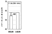
図5に示したように、実施例の方がどの周波数においても比較例よりもイナータンスが小さいことがわかる。これによって実施例は、比較例に比べてNV低減効果が大きいことがわかる。また図6に示したように、200Hz〜1kHzまでのイナータンスの合計は、実施例の方が小さい。したがって実施例は、同様に比較例に比べてNV低減効果が大きいことがわかる。図5および図6からもわかるように、本実施形態の蒸発器10の固定構造がNV低減効果を有するのは明らかである。
As shown in FIG. 5, it can be seen that the inertance of the example is smaller than that of the comparative example at any frequency. Thus, it can be seen that the example has a larger NV reduction effect than the comparative example. Also, as shown in FIG. 6, the total inertance from 200 Hz to 1 kHz is smaller in the example. Therefore, it can be seen that the example has a larger NV reduction effect than the comparative example. As can be seen from FIGS. 5 and 6, it is clear that the fixing structure of the
以上説明したように本実施形態の蒸発器10は外部に設けられる空調ケースに固定される。蒸発器10と空調ケースと固定するための固定部30は、第1の辺31と第3の辺33とで囲まれた面に2つ設けられる。さらに固定部30は、熱交換面11aの四隅を除いた位置であって、蒸発器10の固有振動モードの腹部に対応する位置を除いた位置に設けられる。四隅と腹部を除いた位置は、振動しにくい位置である。換言すると、腹部は最も振動している位置であり、四隅も振動しやすい位置である。このような振動しやすい位置を避けて固定部30を設けるので、振動しにくい部分が空調ケースに固定される。したがって蒸発器10の振動が固定部30から空調ケースに伝わりにくくなる。また固定部30の位置を変えるという簡単な構成で、蒸発器10から空調ケースへの振動を抑制することができる。これによって蒸発器10の振動に起因して、空調ケースが振動することによる騒音を抑制することができる。
As described above, the
また本実施形態では、好ましくは、固定部30は、熱交換面11aの四隅を除いた位置であって、熱交換器の固有振動モードの振幅が四隅よりも小さい位置に設けられる。四隅より振幅が小さい位置で固定することによって、四隅で固定する従来技術よりも、空調ケースに伝わる振動を抑制することができる。これによってNV低減効果を達成することができる。
In the present embodiment, preferably, the fixing
また固定部30が設けられる位置は、さらに好ましくは、1000Hz以下の合成振動モードが最小となる位置である。蒸発器10から車両用空調装置への伝播による騒音は、1000Hz以下に限られる。したがって1000Hz以下の合成振動モードが最小となる位置を固定することによって、空調ケースに伝わる振動をさらに抑制することができる。
The position where the fixing
また固定部30は、蒸発器10の振動モード周波数と、空調ケースの壁面振動の固有振動数とが異なる位置に設けられる。空調ケースの固有振動数は、場所によって異なる。この固有振動数が蒸発器10の振動モード周波数と同じ位置に設けると、蒸発器10から減衰して伝わった振動であっても、空調ケースの固有振動数と同じであると、空調ケースが大きく振動することになる。したがって固定部30を蒸発器10の振動モード周波数と、空調ケースの壁面振動の固有振動数とが異なる位置に設けられることによって、空調ケースの固有振動数に起因してNV低減の効果が小さくなることを抑制することができる。
Moreover, the fixing | fixed
さらに本実施形態では、第1の辺31の長さをLとすると第1の辺31の端部から、0.25L±0.05L離れた位置、および0.75L±0.05L離れた位置の固定部30が設けられる。図3に示すように、0.25Lの位置および0.75Lの位置が節となる位置である。このような節の位置の近傍(±0.05L)に固定部30を設けるので、前述のようにNV低減の効果を達成することができる。
Further, in the present embodiment, when the length of the
換言すると、本実施形態では、車両用空調装置のNV低減のため、蒸発器10の振動モードに着目し、蒸発器10の固定位置の最適化を図ることで車両用空調装置への振動伝播を抑えている。具体的には、蒸発器10の腹部近傍を除いた位置で固定することで車両用空調装置のNV低減が可能になる。そして蒸発器10の節を押さえることで蒸発器10の主要振動モードの空調ケースへの伝達を押さえることができるため車両用空調装置のNV低減が可能である。
In other words, in this embodiment, in order to reduce the NV of the vehicle air conditioner, paying attention to the vibration mode of the
(第2実施形態)
次に、本発明の第2実施形態に関して、図7および図8を用いて説明する。図7では、車両用空調装置を示し、蒸発器10Aは車両用空調装置を構成する要素として示している。図7に示す車両用空調装置を構成する蒸発器10Aは、膨張弁40が一体に設けられている。蒸発器10Aは、冷凍サイクル装置の膨張弁40の流出側に接続され、その膨張弁40で減圧された冷媒が蒸発器10Aに向かって流れる。本実施形態は、固定部30が6箇所に設けられる点に特徴を有する。また各固定部30の構成は、前述の第1実施形態と同様に、凸部によって実現される。
(Second Embodiment)
Next, a second embodiment of the present invention will be described with reference to FIGS. In FIG. 7, the vehicle air conditioner is shown, and the
固定部30は、図7に示すように、上側タンク部12および下側タンク部13のそれぞれに、第1の辺31の端部から、0.25L±0.05L離れた位置、および0.75L±0.05L離れた位置の固定部30が設けられる。第1の辺31における固定部30の位置は、前述の第1実施形態と同様の位置であるので、同様の作用および効果を達成することができる。
As shown in FIG. 7, the fixing
またさらに固定部30は、長さ方向Xの両端部に位置するサイドプレート16のそれぞれに設けられる。具体的には、第2の辺32の長さをWとすると、好ましくは、第2の辺32の端部から0.5W±0.05W離れた位置に固定部30が設けられる。ここで0.5Wとは、0.5×Wの意味である。第2の辺32については、図8に示すように、0.5Wの位置が第2の辺32において節となる位置である。このような節の位置の近傍(±0.05W)に固定部30を設けるので、第1の辺31の固定部30の位置と同様に、NV低減の効果を達成することができる。また本実施形態では、外周の6箇所を固定するので、より強固に空調ケースに蒸発器10を固定することができる。
Furthermore, the fixing
(第3実施形態)
次に、本発明の第3実施形態に関して、図9を用いて説明する。図9では、前述の第1実施形態の蒸発器10とは固定部30Bの構成が異なる点に特徴を有する。本実施形態の蒸発器10Bの固定部30Bは、前述のように下側タンク部13から外方に突出する凸部によって実現される。そして凸部は、弾性部材、たとえば防振ゴムで覆われて構成されている。
(Third embodiment)
Next, a third embodiment of the present invention will be described with reference to FIG. FIG. 9 is characterized in that the configuration of the fixed
このように固定部30Bを凸部および弾性部材で一体に構成することによって、弾性部材を確実に空調ケースに接触させることができる。これによって固定部30Bから空調ケースに伝わる振動をより減衰することができる。
In this way, by integrally configuring the fixing
(第4実施形態)
次に、本発明の第4実施形態に関して、図10を用いて説明する。図10では、前述の第1実施形態の蒸発器10とは固定部30の位置が異なる点に特徴を有する。本実施形態の固定部30の位置は、長さ方向Xの両端部に位置するサイドプレート16のそれぞれに設けられる。具体的には、第2の辺32の長さをWとすると、好ましくは、第2の辺32の端部から0.5W±0.05W離れた位置(図10の仮想線21で示す位置)に固定部30が設けられる。第2の辺32については、図8に示すように、0.5Wの位置が第2の辺32において節となる位置である。このような節の位置の近傍(±0.05W)に固定部30を設けるので、NV低減の効果を達成することができる。
(Fourth embodiment)
Next, a fourth embodiment of the present invention will be described with reference to FIG. FIG. 10 is characterized in that the position of the fixing
(その他の実施形態)
以上、本発明の好ましい実施形態について説明したが、本発明は上述した実施形態に何ら制限されることなく、本発明の主旨を逸脱しない範囲において種々変形して実施することが可能である。
(Other embodiments)
The preferred embodiments of the present invention have been described above, but the present invention is not limited to the above-described embodiments, and various modifications can be made without departing from the spirit of the present invention.
上記実施形態の構造は、あくまで例示であって、本発明の範囲はこれらの記載の範囲に限定されるものではない。本発明の範囲は、特許請求の範囲の記載によって示され、さらに特許請求の範囲の記載と均等の意味及び範囲内での全ての変更を含むものである。 The structure of the said embodiment is an illustration to the last, Comprising: The scope of the present invention is not limited to the range of these description. The scope of the present invention is indicated by the description of the scope of claims, and further includes meanings equivalent to the description of the scope of claims and all modifications within the scope.
前述の第1実施形態では、固定部30は2箇所であったが、2箇所に限るものではなく、第1の辺31と第3の辺33とで囲まれた面、および第2の辺32と第3の辺33とで囲まれた面の少なくともいずれか一方の面に、少なくとも1つの固定部30が設けらていればよい。したがって、たとえばサイドプレート16だけに固定部30を設けてもよい。
In the first embodiment described above, the number of fixing
前述の第1実施形態では、車両用空調装置を構成する蒸発器10であったが、車両用に限るものではなく、家庭用の空調装置を構成する蒸発器であってもよい。また蒸発器に限るものではなく、内部に冷媒が流れる直方体形状の熱交換器であれば、放熱器や凝縮器であってもよい。
In the first embodiment described above, the
X…長さ方向 Y…幅方向 Z…厚さ方向
10…蒸発器(熱交換器) 11…コア部 11a…熱交換面
12…上側タンク部 13…下側タンク部 14…扁平チューブ
15…コルゲートフィン 16…サイドプレート 17…接続ブロック
18…流入口 19…流出口 30…固定部
31…第1の辺 32…第2の辺 33…第3の辺
40…膨張弁
X ... length direction Y ... width direction Z ...
Claims (2)
前記直方体形状の前記熱交換器を構成する辺を、第1の辺(31)、第2の辺(32)および第3の辺(33)とした場合、前記第3の辺の長さが最も小さく、
前記第1の辺と前記第2の辺とで囲まれた面は、熱交換面(11a)であり、
前記第1の辺と前記第3の辺とで囲まれた面、および前記第2の辺と前記第3の辺とで囲まれた面の少なくともいずれか一方の面に、少なくとも1つの前記ケースに固定するための固定部(30,30B)が設けられ、
前記固定部は、前記熱交換面の四隅を除いた位置であって、前記熱交換器の固有振動モードの腹部に対応する位置を除いた位置であり、1000Hz以下の合成振動モードが最小となる位置に設けられることを特徴とする熱交換器の固定構造。 A fixed structure of a heat exchanger (10, 10A, 10B, 10C) having a rectangular parallelepiped shape that is fixed to a case provided outside and in which a refrigerant flows.
When the sides constituting the rectangular parallelepiped heat exchanger are the first side (31), the second side (32), and the third side (33), the length of the third side is Smallest,
The surface surrounded by the first side and the second side is a heat exchange surface (11a),
At least one of the cases on at least one of the surface surrounded by the first side and the third side and the surface surrounded by the second side and the third side A fixing part (30, 30B) is provided for fixing to
The fixed part is a position excluding the four corners of the heat exchange surface, excluding the position corresponding to the abdomen of the natural vibration mode of the heat exchanger , and the combined vibration mode of 1000 Hz or less is minimized. A heat exchanger fixing structure characterized by being provided at a position .
Priority Applications (5)
| Application Number | Priority Date | Filing Date | Title |
|---|---|---|---|
| JP2012262209A JP5920190B2 (en) | 2012-11-30 | 2012-11-30 | Heat exchanger fixing structure |
| US14/648,209 US20150300756A1 (en) | 2012-11-30 | 2013-10-21 | Fixing structure for heat exchanger |
| CN201380062581.5A CN104822554B (en) | 2012-11-30 | 2013-10-21 | The fixed structure of heat exchanger |
| DE112013005735.2T DE112013005735T5 (en) | 2012-11-30 | 2013-10-21 | Mounting structure for a heat exchanger |
| PCT/JP2013/006212 WO2014083754A1 (en) | 2012-11-30 | 2013-10-21 | Fixing structure for heat exchanger |
Applications Claiming Priority (1)
| Application Number | Priority Date | Filing Date | Title |
|---|---|---|---|
| JP2012262209A JP5920190B2 (en) | 2012-11-30 | 2012-11-30 | Heat exchanger fixing structure |
Publications (3)
| Publication Number | Publication Date |
|---|---|
| JP2014108633A JP2014108633A (en) | 2014-06-12 |
| JP2014108633A5 JP2014108633A5 (en) | 2015-03-26 |
| JP5920190B2 true JP5920190B2 (en) | 2016-05-18 |
Family
ID=50827419
Family Applications (1)
| Application Number | Title | Priority Date | Filing Date |
|---|---|---|---|
| JP2012262209A Active JP5920190B2 (en) | 2012-11-30 | 2012-11-30 | Heat exchanger fixing structure |
Country Status (5)
| Country | Link |
|---|---|
| US (1) | US20150300756A1 (en) |
| JP (1) | JP5920190B2 (en) |
| CN (1) | CN104822554B (en) |
| DE (1) | DE112013005735T5 (en) |
| WO (1) | WO2014083754A1 (en) |
Families Citing this family (5)
| Publication number | Priority date | Publication date | Assignee | Title |
|---|---|---|---|---|
| JP6051935B2 (en) | 2013-02-26 | 2016-12-27 | 株式会社デンソー | Heat exchanger |
| JP6350373B2 (en) | 2015-04-17 | 2018-07-04 | 株式会社デンソー | Evaporator |
| JP6804269B2 (en) * | 2016-11-18 | 2020-12-23 | 三菱重工サーマルシステムズ株式会社 | Heat exchanger |
| CN110118174A (en) * | 2019-04-22 | 2019-08-13 | 安徽大富重工机械有限公司 | A kind of compressor and automotive air-conditioning system |
| JP7200906B2 (en) * | 2019-10-24 | 2023-01-10 | 株式会社デンソー | vehicle air conditioner |
Family Cites Families (17)
| Publication number | Priority date | Publication date | Assignee | Title |
|---|---|---|---|---|
| JPS5784223A (en) * | 1980-11-13 | 1982-05-26 | Nissan Motor Co Ltd | Vibration absorber of vehicle |
| JPS5846986U (en) * | 1981-09-22 | 1983-03-30 | 三菱重工業株式会社 | Shell-and-tube heat exchanger |
| JPS6288608A (en) * | 1985-10-14 | 1987-04-23 | Mitsubishi Heavy Ind Ltd | Evaporator unit for air conditioner for vehicle |
| JPH0342708U (en) * | 1989-08-30 | 1991-04-23 | ||
| DE4102264C2 (en) * | 1991-01-26 | 2003-03-27 | Continental Teves Ag & Co Ohg | Hydraulic power steering for motor vehicles |
| JP3687150B2 (en) * | 1995-05-17 | 2005-08-24 | 株式会社デンソー | Heat exchanger support device |
| JPH10269539A (en) * | 1997-03-19 | 1998-10-09 | Fujitsu Ltd | Structure and jig for fitting spring arm to head arm |
| JP2000146217A (en) * | 1998-11-12 | 2000-05-26 | Hitachi Ltd | Indoor machine of air conditioner |
| JP2002139289A (en) * | 2000-06-08 | 2002-05-17 | Denso Corp | Heat exchanger |
| US6558137B2 (en) * | 2000-12-01 | 2003-05-06 | Tecumseh Products Company | Reciprocating piston compressor having improved noise attenuation |
| JP2003336935A (en) * | 2002-05-21 | 2003-11-28 | Denso Corp | Heat exchanger |
| US7150604B2 (en) * | 2004-03-15 | 2006-12-19 | Carrier Corporation | Electric box for compressor assembly |
| JP2008247105A (en) * | 2007-03-29 | 2008-10-16 | Denso Corp | Air conditioner |
| FR2953774B1 (en) * | 2009-12-11 | 2012-03-02 | Peugeot Citroen Automobiles Sa | DEVICE FOR FIXING A HEAT EXCHANGER OF A MOTOR VEHICLE |
| CN201626282U (en) * | 2010-03-12 | 2010-11-10 | 杨顺福 | Automobile air conditioner condenser with oscillating damper |
| JP2012001124A (en) * | 2010-06-17 | 2012-01-05 | Japan Climate Systems Corp | Vehicular air conditioner |
| CN201808425U (en) * | 2010-09-30 | 2011-04-27 | 重庆长安汽车股份有限公司 | Commercial vehicle top-mounted evaporator installation structure |
-
2012
- 2012-11-30 JP JP2012262209A patent/JP5920190B2/en active Active
-
2013
- 2013-10-21 CN CN201380062581.5A patent/CN104822554B/en active Active
- 2013-10-21 US US14/648,209 patent/US20150300756A1/en not_active Abandoned
- 2013-10-21 WO PCT/JP2013/006212 patent/WO2014083754A1/en active Application Filing
- 2013-10-21 DE DE112013005735.2T patent/DE112013005735T5/en not_active Ceased
Also Published As
| Publication number | Publication date |
|---|---|
| WO2014083754A1 (en) | 2014-06-05 |
| DE112013005735T5 (en) | 2015-11-26 |
| CN104822554A (en) | 2015-08-05 |
| US20150300756A1 (en) | 2015-10-22 |
| JP2014108633A (en) | 2014-06-12 |
| CN104822554B (en) | 2017-06-09 |
Similar Documents
| Publication | Publication Date | Title |
|---|---|---|
| JP6051935B2 (en) | Heat exchanger | |
| JP5920190B2 (en) | Heat exchanger fixing structure | |
| US20070084589A1 (en) | Evaporator | |
| JP5875918B2 (en) | Car interior heat exchanger and inter-header connection member of car interior heat exchanger | |
| JP2007298260A (en) | Heat exchanger | |
| JP2013178007A (en) | Parallel flow heat exchanger and device including the same | |
| US10969180B2 (en) | Air-conditioning unit | |
| WO2014068842A1 (en) | Refrigerant evaporation device | |
| JP2013249971A (en) | Heat exchanger | |
| JP6044477B2 (en) | Vehicle heat exchanger | |
| JP2013134016A (en) | Heat exchanger | |
| JP2000213888A (en) | Heating, ventilating, or air-conditioning device with heat- exchange device | |
| JP2018189337A (en) | Refrigerant evaporator and its manufacturing method | |
| JP2010065989A (en) | Tube for heat exchanger and heat exchanger | |
| JP6297808B2 (en) | Heat exchanger | |
| JP2016176678A (en) | Cold storage heat exchanger | |
| KR102371382B1 (en) | A tube for heat exchanger | |
| JP2018115775A (en) | Heat exchanger | |
| JP2000213887A (en) | Heating, ventilating, or air-conditioning device including heat loop with heat exchanger | |
| KR101890867B1 (en) | Evaporator | |
| KR100723809B1 (en) | Heat exchanger | |
| JP4144124B2 (en) | Heat exchanger | |
| JP7426456B1 (en) | Indoor heat exchanger and air conditioner | |
| JP2011169522A (en) | Heat exchanger | |
| JP2019148389A (en) | Evaporator |
Legal Events
| Date | Code | Title | Description |
|---|---|---|---|
| A621 | Written request for application examination |
Free format text: JAPANESE INTERMEDIATE CODE: A621 Effective date: 20150128 |
|
| A521 | Request for written amendment filed |
Free format text: JAPANESE INTERMEDIATE CODE: A523 Effective date: 20150206 |
|
| TRDD | Decision of grant or rejection written | ||
| A01 | Written decision to grant a patent or to grant a registration (utility model) |
Free format text: JAPANESE INTERMEDIATE CODE: A01 Effective date: 20160315 |
|
| A61 | First payment of annual fees (during grant procedure) |
Free format text: JAPANESE INTERMEDIATE CODE: A61 Effective date: 20160328 |
|
| R151 | Written notification of patent or utility model registration |
Ref document number: 5920190 Country of ref document: JP Free format text: JAPANESE INTERMEDIATE CODE: R151 |
|
| R250 | Receipt of annual fees |
Free format text: JAPANESE INTERMEDIATE CODE: R250 |
|
| R250 | Receipt of annual fees |
Free format text: JAPANESE INTERMEDIATE CODE: R250 |
|
| R250 | Receipt of annual fees |
Free format text: JAPANESE INTERMEDIATE CODE: R250 |
|
| R250 | Receipt of annual fees |
Free format text: JAPANESE INTERMEDIATE CODE: R250 |
|
| R250 | Receipt of annual fees |
Free format text: JAPANESE INTERMEDIATE CODE: R250 |
|
| R250 | Receipt of annual fees |
Free format text: JAPANESE INTERMEDIATE CODE: R250 |