JP5920162B2 - Upper car body structure of open car - Google Patents
Upper car body structure of open car Download PDFInfo
- Publication number
- JP5920162B2 JP5920162B2 JP2012228241A JP2012228241A JP5920162B2 JP 5920162 B2 JP5920162 B2 JP 5920162B2 JP 2012228241 A JP2012228241 A JP 2012228241A JP 2012228241 A JP2012228241 A JP 2012228241A JP 5920162 B2 JP5920162 B2 JP 5920162B2
- Authority
- JP
- Japan
- Prior art keywords
- vehicle
- roll bar
- seat back
- leg
- seat
- Prior art date
- Legal status (The legal status is an assumption and is not a legal conclusion. Google has not performed a legal analysis and makes no representation as to the accuracy of the status listed.)
- Expired - Fee Related
Links
Images


Description
本発明は、オープンカーの上部車体構造、特に、オープンカーにおけるロールバー構造に関する。 The present invention relates to an upper car body structure of an open car, and more particularly to a roll bar structure in an open car.
オープンカーにおいては、横転時に乗員を保護するための手段として、ロールバー構造が備えられることがある。一般的に、このロールバー構造としては、逆U字状の形態をなすロールバーを上方へ突出するように車両後部のシートバックの後方に設けるものが知られている。 In an open car, a roll bar structure may be provided as a means for protecting an occupant during rollover. In general, as this roll bar structure, a roll bar having an inverted U-shape is provided behind the seat back at the rear of the vehicle so as to protrude upward.
例えば、特許文献1には、逆U字状の形態をなすロールバーを含んだロールバー構造であって、ロールバーの上部がシートバックの後方において車幅方向に平行になるように設けられたロールバー構造が開示されている。また、特許文献2には、逆U字状の形態をなすロールバーを、車室後部のコーナー部を跨ぐように架設されたロールバー構造が開示されている。
For example,
ここで、オープンカーにおけるロールバー構造は、所望の前後移動量を有するように構成されたシートの最後方位置におけるシートに干渉しないように前後位置が設定されており、且つ、横転時の乗員の保護性能を考慮してその高さが設定されている。 Here, the roll bar structure in the open car has the front and rear positions set so as not to interfere with the seat at the rearmost position of the seat configured to have a desired front and rear movement amount, and the occupant at the time of rollover The height is set in consideration of protection performance.
また、オープンカーにおいては、幌またはリトラクタブルハードトップ等からなる開閉式ルーフ部材を折りたたんで車室内に回動格納することが行われており、シート後方の車室後部に、折りたたんだルーフ部材を格納するためのルーフ部材格納部が設けられる。そして、ルーフ部材をルーフ部材格納部へ格納する際のルーフ部材格納軌跡は、シートバック及びロールバー構造と干渉しないように設定されており、その結果、ルーフ部材格納部はルーフ部材格納軌跡上のリヤデッキ後方に位置することになる。すなわち、ルーフ部材格納部は、ルーフ部材格納軌跡を考慮して、シートバック及びロールバー構造の後方のリヤデッキへ設けられることになる。 In an open car, an openable / closable roof member such as a hood or a retractable hard top is folded and retracted into the passenger compartment, and the folded roof member is stored at the rear of the passenger compartment. A roof member storage is provided. The roof member storage locus when the roof member is stored in the roof member storage portion is set so as not to interfere with the seat back and the roll bar structure. As a result, the roof member storage portion is located on the roof member storage locus. It will be located behind the rear deck. In other words, the roof member storage portion is provided on the rear deck behind the seat back and roll bar structure in consideration of the roof member storage locus.
ところで、前記のような構成のオープンカーにおいては、車両のコンパクト化の要請やデザイン上の要請から、車室の前後寸法の短縮を図ろうとした場合、ルーフ部材格納部の位置を車両前後方向の前方に寄せるか、又は、ルーフ部材格納部自体の前後寸法を短縮するか等の変更が必要となる。しかしながら、上述したように、ルーフ部材格納部の前後位置はシート、ロールバー構造及びルーフ部材格納軌跡との位置関係から決まっているため、ルーフ部材格納部を単独で車両前後方向の前方に寄せることは困難であり、また、ルーフ収納部自体の前後寸法はルーフの長さによって決まっているため短縮することは困難である。 By the way, in the open car having the above-described configuration, when it is attempted to reduce the front-rear dimension of the passenger compartment due to a request for compactness of the vehicle or a design, the position of the roof member storage portion is set in the vehicle front-rear direction. It is necessary to change whether to move forward or to shorten the longitudinal dimension of the roof member storage portion itself. However, as described above, the front and rear positions of the roof member storage portion are determined from the positional relationship between the seat, the roll bar structure, and the roof member storage locus, and therefore the roof member storage portion is moved forward in the vehicle front-rear direction alone. In addition, since the front and rear dimensions of the roof storage portion itself are determined by the length of the roof, it is difficult to reduce the size.
このため、車室の前後寸法を短縮するには、シートの最後方位置を車両前後方向の前方に寄せることによってロールバー構造及びルーフ部材格納部を車両前後方向の前方に寄せることが必要になる。この結果、シートの所望の前後移動量を確保することが困難となり、様々な体型の乗員、特に、大きな体型の乗員に対して適正な乗車姿勢を提供することが困難になるという、問題が生じる。 For this reason, in order to shorten the longitudinal dimension of the passenger compartment, it is necessary to bring the roll bar structure and the roof member storage portion forward in the vehicle longitudinal direction by moving the rearmost position of the seat forward in the vehicle longitudinal direction. . As a result, it becomes difficult to secure a desired amount of forward and backward movement of the seat, and there arises a problem that it is difficult to provide an appropriate riding posture for passengers of various body types, particularly passengers of large body types. .
その場合に、特許文献1に開示されたロールバー構造では、シートとロールバー構造とルーフ部材格納部とが前から順に並ぶように配置されているためシートバックの中央部とロールバーの頂部とが正対する位置関係となり、特許文献2に開示されたロールバー構造では、ロールバーの車幅方向の内側の部分がシートの後方において車両の車幅方向の内側へ大きく入り込んでいるため、シートバックの中央部とロールバーの頂部とがほぼ正対する位置関係となる。
In that case, in the roll bar structure disclosed in
すなわち、いずれも、ロールバーの頂部とシートバックの中央部とが車両前後方向に正対する位置関係となるため、シートを車両前後方向の前方へ寄せることなく、ロールバーのみを車両前後方向の前方に寄せることは困難である。したがって、ロールバーが、シートの最後方位置に基づくシートの所望の前後移動量を確保しながら、ルーフ部材格納部を車両前後方向の前方へ移動させて、車室の前後寸法を短縮することの妨げとなる。 That is, in both cases, since the top portion of the roll bar and the central portion of the seat back are in a positional relationship facing the vehicle longitudinal direction, only the roll bar is moved forward in the vehicle longitudinal direction without bringing the seat forward in the vehicle longitudinal direction. It is difficult to get to. Accordingly, the roll bar moves the roof member storage portion forward in the vehicle front-rear direction while ensuring the desired amount of front-rear movement of the seat based on the rearmost position of the seat, thereby shortening the front-rear dimension of the passenger compartment. Hinder.
この発明は上記の課題を解決するためになされたものであり、すなわち、シートの所望の前後移動量を確保しながら、車室の前後寸法の短縮を可能とする、ロールバー構造を得ることを目的とする。 The present invention has been made to solve the above-described problem, that is, to obtain a roll bar structure capable of shortening the front-rear dimension of the passenger compartment while ensuring a desired front-rear movement amount of the seat. Objective.
前記課題を解決するため、本発明は次のように構成したことを特徴とする。 In order to solve the above problems, the present invention is configured as follows.
まず、本願の請求項1に記載の発明は、車室内におけるシート後方のリヤデッキ上にルーフ部材格納部が設けられ、該格納部にルーフ部材が回動格納されるオープンカーの上部車体構造において、前記ルーフ部材格納部の車両前後方向の前方に、前記シートを構成するシートバックの車外側の側方に位置する車外側脚部と、前記シートバックの車両前後方向の後方において該シートバックの車幅方向の中央よりも車外側に位置する車内側脚部とを有する逆U字状のロールバーを左右に配置し、前記ロールバーの上部は、車両前後方向の前方かつ車内側に折れ曲がっていることを特徴とする。
First, the invention according to
また、請求項2に記載の発明は、請求項1に記載の発明において、前記車内側脚部は、前記シートバックの上部中央に設けられたヘッドレストよりも車外側に位置することを特徴とする。
The invention according to
また、請求項3に記載の発明は、請求項1又2に記載の発明において、前記車外側脚部及び前記車内側脚部が、前記シートバックのショルダー部の高さまで、それぞれほぼ垂直に延びていることを特徴とする。 According to a third aspect of the present invention, in the first or second aspect of the present invention, the vehicle outer leg and the vehicle inner leg extend substantially vertically up to the height of the shoulder portion of the seat back. It is characterized by.
また、請求項4に記載の発明は、請求項1から請求項3のいずれか1つに記載の発明において、ロールバーの車外側脚部の下部は、その車外側に位置する車体の側壁に連結部材を介して連結されていることを特徴とする。 According to a fourth aspect of the present invention, in the invention according to any one of the first to third aspects, the lower part of the outer leg portion of the roll bar is located on the side wall of the vehicle body located outside the car. It is connected via a connecting member.
まず、請求項1の本発明によれば、ロールバーの車外側脚部をシートバックの側方に配置し、且つ、ロールバーの車内側脚部をシートバックの中央部よりも車外側に配置しているため、両脚部を逆U字状に結んだロールバーの頂部は、シートバックの中央部を車外側に避けつつ従来のロールバー構造に係るロールバーの頂部よりも車両前後方向の前方に位置することになる。この配置によって、ルーフ部材格納部を車両前後方向の前方に寄せることが可能となる。 First, according to the first aspect of the present invention, the outer leg portion of the roll bar is disposed on the side of the seat back, and the inner leg portion of the roll bar is disposed on the outer side of the center portion of the seat back. Therefore, the top of the roll bar that connects both legs in an inverted U-shape is more forward in the vehicle longitudinal direction than the top of the roll bar according to the conventional roll bar structure while avoiding the center part of the seat back to the outside of the vehicle. Will be located. With this arrangement, the roof member storage part can be moved forward in the vehicle front-rear direction.
つまり、一般的にシートバックは車幅方向の中央部が最も背が高く、これに伴い平面視においてはシートバックの中央部が後方へ最も突出することになる。したがって、ロールバーの頂部が後方へ最も突出したシートバックの中央部と車両前後方向に正対することを避ければ、ロールバーを車両前後方向の前方に位置することによって、該ロールバーの頂部とルーフ部材格納軌跡との隙間を拡大できる。 That is, the seat back is generally tallest at the center in the vehicle width direction, and accordingly, the center of the seat back projects most backward in plan view. Therefore, if the roll bar is positioned in front of the vehicle front-rear direction, the top of the roll bar and the roof can be avoided by avoiding the roll bar from facing the vehicle front-rear direction to the center of the seat back that protrudes most backward. A gap with the member storage locus can be enlarged.
この結果、シートの最後方位置を車両前後方向の前方に寄せることなく、ルーフ部材格納軌跡を車両前後方向の前方に寄せると共にルーフ部材格納部を車両前後方向の前方へ寄せることが可能となる。従って、本発明によれば、シートの所望の前後移動量を確保しながら、車室の前後寸法を短縮することが可能となる。 As a result, it is possible to move the roof member storage locus forward in the vehicle longitudinal direction and move the roof member storage portion forward in the vehicle longitudinal direction without moving the rearmost position of the seat forward in the vehicle longitudinal direction. Therefore, according to the present invention, the front-rear dimension of the passenger compartment can be shortened while ensuring the desired front-rear movement amount of the seat.
さらに、ロールバーの頂部がシートバックの中央部よりも車外側へ位置することによって、車両の横転時においてロールバーの頂部が障害物に接触するタイミングを早めることができるので、乗員保護性能を向上できる。 Furthermore, since the top of the roll bar is positioned outside the center of the seat back, the timing at which the top of the roll bar contacts an obstacle when the vehicle rolls over can be improved, thereby improving occupant protection performance. it can.
また、ロールバーの車外側脚部はシートバックの側方に位置して、車内側脚部をシートバックの車両前後方向の後方に位置している。つまり、両脚部はそれぞれ車幅方向及び車両前後方向に位置をずらして位置しているため、車幅方向及び車両前後方向のいずれかの方向からの外力がロールバーに作用しても、ロールバーの車外側脚部と車内側脚部との間に効果的に支え合う関係が成立することになり、車幅方向及び車両前後方向のいずれの方向からの外力に対しても、常に効果的に抗することができる。
また、車内側脚部を折り曲げて車両前後方向の前側に向けて傾斜させることによって、ロールバーの頂部がシートバックと干渉することなく、より前方のシートバックのショルダー部の上方へ位置することになる。これによって、ロールバーの頂部とルーフ部材格納軌跡との隙間をさらに拡大できるので、ルーフ部材格納軌跡をさらに車両前後方向の前方に寄せると共にルーフ部材格納部をさらに車両前後方向の前方に寄せることが可能となる。
従って、シートの最後方位置を車両前後方向の前方に寄せることなくルーフ部材格納部を車両前後方向の前方に寄せることが可能となるため、シートの所望の前後移動量を確保しながら、車室の前後寸法を短縮することが可能となる。
Further, the vehicle leg of the roll bar is located on the side of the seat back, and the vehicle inner leg is located behind the seat back in the vehicle front-rear direction. In other words, since both the leg portions are shifted from each other in the vehicle width direction and the vehicle front-rear direction, the roll bar can be applied even if an external force from either the vehicle width direction or the vehicle front-rear direction acts on the roll bar. Therefore, an effective support relationship is established between the vehicle outer leg and the vehicle inner leg, and it is always effective against external forces from either the vehicle width direction or the vehicle front-rear direction. Can withstand.
In addition, by bending the vehicle inner leg portion and inclining toward the front side in the vehicle longitudinal direction, the top of the roll bar is positioned above the shoulder portion of the front seat back without interfering with the seat back. Become. As a result, the gap between the top of the roll bar and the roof member storage locus can be further enlarged, so that the roof member storage locus can be further moved forward in the vehicle longitudinal direction and the roof member storage portion can be further moved forward in the vehicle longitudinal direction. It becomes possible.
Accordingly, the roof member storage portion can be moved forward in the vehicle front-rear direction without moving the rearmost position of the seat forward in the vehicle front-rear direction. It becomes possible to shorten the front and rear dimensions.
また、請求項2に記載の発明によれば、車内側脚部はシートバック上部のヘッドレスト部を避けて、シートバックのショルダー部と正対することになるため、ロールバーの頂部はヘッドレストの側方であって、従来のロールバー構造に係るロールバーの頂部よりも車両前後方向の前方に位置することになる。この配置によって、請求項1に係る発明を容易に達成できる。
According to the second aspect of the present invention, since the vehicle inner leg portion faces the shoulder portion of the seat back while avoiding the headrest portion at the upper portion of the seat back, the top portion of the roll bar is located on the side of the headrest. And it will be located ahead of the direction of vehicles order rather than the top part of the roll bar concerning the conventional roll bar structure. With this arrangement, the invention according to
つまり、ロールバーの頂部が従来のロールバー構造に係るロールバーの頂部よりも車両前後方向の前方に位置することによって、ロールバーの頂部とルーフ部材格納軌跡との隙間を拡大できるため、ルーフ部材格納軌跡を車両前後方向の前方に寄せることが可能となる。従って、シートの最後方位置を車両前後方向の前方に寄せることなくルーフ部材格納部を車両前後方向の前方に寄せることが可能となるため、シートの所望の前後移動量を確保しながら、車室の前後寸法を短縮することが可能となる。 That is, since the top of the roll bar is positioned in front of the roll bar in the vehicle longitudinal direction relative to the top of the roll bar according to the conventional roll bar structure, the gap between the top of the roll bar and the roof member storage locus can be expanded. It is possible to bring the storage locus forward in the vehicle front-rear direction. Accordingly, the roof member storage portion can be moved forward in the vehicle front-rear direction without moving the rearmost position of the seat forward in the vehicle front-rear direction. It becomes possible to shorten the front and rear dimensions.
また、車内側脚部をシートバックのヘッドレストを車外側へ避けた位置に設定することによって、シートを後傾させた際にヘッドレストとロールバーの車内側脚部とが干渉することを回避することができる。 In addition, by setting the inner leg of the vehicle at a position that avoids the headrest of the seat back to the outer side of the vehicle, it is possible to avoid interference between the headrest and the inner leg of the roll bar when the seat is tilted backward. Can do.
つまり、平面視において、ロールバーの頂部とシートバックのショルダー部とが重複した位置にまでシートバックを後傾させることができるので、シートバックの後傾量を増大させることができる。従って、シート最後方位置においてもシートをより後傾できるようになるため、より体型の大きな乗員に対しても適正な運転姿勢を提供することが可能となる。 That is, since the seat back can be tilted backward to a position where the top of the roll bar and the shoulder portion of the seat back overlap in plan view, the amount of backward tilt of the seat back can be increased. Accordingly, since the seat can be tilted further backward even at the rearmost position of the seat, it is possible to provide an appropriate driving posture even for a passenger with a larger body shape.
また、請求項3に記載の発明によれば、シートバックのショルダー部の高さまで、車外側脚部が上下に延びていることによって、シートバックの側方にはショルダー部の高さまで車外側脚部が位置することになる。この結果、側突時における側突荷重に対してロールバーの車外側脚部が確実に抗するので、側突荷重が直接にシートに伝わるのを防ぎ、乗員保護性能を向上できる。 According to the third aspect of the present invention, the vehicle outer leg extends up and down to the height of the shoulder portion of the seat back, so that the vehicle outer leg extends to the height of the shoulder portion on the side of the seat back. The part will be located. As a result, the vehicle leg of the roll bar reliably resists the side impact load at the time of a side impact, so that the side impact load is prevented from being directly transmitted to the seat, and the occupant protection performance can be improved.
また、請求項4に記載の発明によれば、ロールバーを車両側壁と連結することによって、シートバックの車外側に位置するロールバーの車外側脚部の支持剛性を高めることができるので、ロールバー構造の耐力が向上するため、車両横転時や側突時における乗員保護性能を向上できる。
According to the invention of
以下、本発明に係るオープンカーの上部車体構造を適用した実施形態について説明する。 Hereinafter, an embodiment to which an upper car body structure of an open car according to the present invention is applied will be described.
図1は、本発明の実施形態に係るオープンカーの上部車体構造(ロールバー構造)を備えた車両の後方部分を示す斜視図である。図1に示すように、車両1は、車室の床を構成するフロアパネル2と、このフロアパネル2の中央部から上方に突出し車両前後方向に延びるフロアトンネル4と、これらのフロアパネル2及びフロアトンネル4の後端部において斜め上方に傾斜して延びるキックアップパネル6と、このキックアップパネル6の上端部から車両後方に延びルーフ部材格納部Rの床を構成するリヤデッキ10と、リヤデッキ10の後端部で上方に延びるリヤパネル12と、車両の両側面を構成する上下方向に延びる一対のサイドパネル14と、を備えている。
FIG. 1 is a perspective view showing a rear portion of a vehicle provided with an upper car body structure (roll bar structure) of an open car according to an embodiment of the present invention. As shown in FIG. 1, a
フロアパネル2にはフロアトンネル4の左右両側においてそれぞれ車幅方向に延びる前側シートブラケット(図示せず)と、後ろ側シートブラケット(図示せず)とが設けられ、これらのシートブラケットにシート20が取り付けられている。シート20は周知の機構によって車両前後方向に移動可能に構成されており、乗員の上半身を支持するシートバック22を有する。さらに、シートバック22は周知の機構によって角度変更可能に構成されており、上部中央に乗員の頭部を支持するヘッドレスト部222を有する。
The
さらに、車両1は、シートバック22の車外側のショルダー部224を囲むロールバー構造30を備えている。このロールバー構造30は、上下方向に延びる逆U字状の形態をなす左右一対のロールバー32と、一対のサイドパネル14の間で車幅方向に延びるクロスバー34と、クロスバー34とサイドパネル14とを連結する左右一対のガセット36と、ロールバー32とサイドパネル14とを連結する左右一対の下方連結部材38と、を備えている。
Further, the
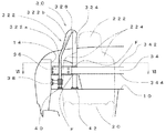
次に、図2〜図6を参照して、このロールバー構造30のロールバー32の構成をより具体的に説明する。図2は同ロールバー構造の右側のみを示す要部斜視図であり、図3は同ロールバー構造の右側のみを示す要部正面図であり、図4は同ロールバー構造の右側のみを示す要部側面図であり、図5は同ロールバー構造の右側のみを示す要部平面図であり、図6は図3のVI−VI線における同ロールバー構造の断面図である。
Next, the configuration of the
まず、図2に示すように、ロールバー32は、1本の楕円断面のパイプを逆U字状に形成したものであり、上下方向に延びるように配置されている。このロールバー32は、シートバック22の側方に位置する車外側脚部322と、シートバック22の車両前後方向の後方においてシートバック22の車幅方向の中央よりも車外側に位置する車内側脚部324と、車外側脚部322と車内側脚部324とをつなぐように逆U字状に大きく曲げられた頂部326と、を有する。
First, as shown in FIG. 2, the
図3に示すように、車外側脚部322は、シートバック22のショルダー部224の高さまで上下方向に延びる車外側脚部鉛直部322aと、シートバック22のショルダー部224の高さから折れ曲って車内側へ向けて傾斜している車外側脚部傾斜部322bとを有する。また、図6に示すように、車外側脚部322は、車外側脚部鉛直部322aをその楕円断面の長径方向を車両の前後方向に平行になるように、配置されている。
As shown in FIG. 3, the vehicle
図4に示すように、車内側脚部324は、シートバック22のショルダー部224の高さまで上下方向に延びる車内側脚部鉛直部324aと、シートバック22のショルダー部224の高さから折れ曲って車両前後方向の前方へ向けて傾斜している車内側脚部傾斜部324bとを有する。また、図6に示すように、車内側脚部324は、車内側脚部鉛直部324aをその楕円断面の長径方向を車幅方向に平行になるように、配置されている。 As shown in FIG. 4, the vehicle inner leg 324 is bent from the vehicle inner leg vertical portion 324 a extending vertically to the height of the shoulder 224 of the seat back 22 and the height of the shoulder 224 of the seat back 22. And a vehicle interior leg inclined portion 324b that is inclined forward in the vehicle longitudinal direction. Further, as shown in FIG. 6, the vehicle inner leg 324 is arranged so that the vehicle inner leg vertical portion 324a is parallel to the vehicle width direction in the major axis direction of its elliptical cross section.
図5に示すように、平面視において車外側脚部322は車幅方向に延び、車内側脚部324は車両前後方向に延びている。つまり、車外側脚部322と車内側脚部324とは直角の位置関係にあり、両傾斜部322b及び324bをつなぐようにロールバーの頂部326が形成されている。これによって、ロールバーの頂部326は、平面視において両脚部322及び324が交わる交点となるシートバック22のヘッドレスト部222の車外側であって、ショルダー部224の上方に位置している。
As shown in FIG. 5, the vehicle
図2〜図5に示すように、車外側脚部322は、その下端部においてフランジ40を介してボルトでリヤデッキ10に固定されている。同様に、車内側脚部324も、その下端部においてフランジ42を介してボルトでリヤデッキ20に固定されている。また、車内側脚部鉛直部324aは、クロスバー34を上下に貫通している。フランジ40及びフランジ42は、ロールバー32の両脚部322及び324にその下端部において溶接によってそれぞれ結合されている。
2-5, the vehicle outer
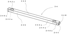
次に、図7を参照して、このロールバー構造30のクロスバー34の構成を具体的に説明する。図7はクロスバー34を示す斜視図である。図7に示すように、クロスバー34は矩形状の閉断面構造を有する。クロスバー34は、上壁部342と、下壁部344と、前側縦壁部346と、後側縦壁部348と、を有する。クロスバー34の前側縦壁部346の両端部には、左右一対のボルト通し孔346aが上下に2つ形成されている。
Next, the configuration of the
また、クロスバー34の上壁部342及び下壁部344には、ボルト通し孔346aよりも車幅方向内側の位置に左右一対の開口部342a及び344aが形成され、該開口部342a及び344aにロールバー32の車内側脚部鉛直部324aが上下方向に貫通するようになっている。
In addition, a pair of left and right openings 342a and 344a are formed in the upper wall portion 342 and the lower wall portion 344 of the
開口部342a及び344aの大きさは、ロールバー32の車内側脚部鉛直部324aの楕円断面よりも少し大きく形成されており、車内側脚部鉛直部324aが容易に挿入できるようになっている。また、後述するように、車外側脚部鉛直部324aとクロスバー34の上壁部342及び下壁部344とを、開口部342a及び344aに沿って溶接できるように、適切な隙間関係となるような大きさに設定されている。
The sizes of the openings 342a and 344a are formed slightly larger than the elliptical cross section of the vehicle interior leg vertical portion 324a of the
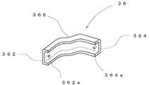
次に、図8を参照して、このロールバー構造30のガセット36の構成を具体的に説明する。図8はガセット36を示す斜視図である。図8に示すように、ガセット36は車両前後方向の前方に向けて開放したコの字状の断面を有する板状部材であって、車外側端部において車両前後方向に延びる第1直線部362と、車内側端部において車幅方向に延びる第2直線部364と、第1直線部362と第2直線部364とをつなぐ連結部366と、を有している。
Next, the configuration of the
ガセット36の第1直線部362及び第2直線部364には、それぞれボルト通し孔362a及び364aが上下に2つそれぞれ形成されている。また、ガセット36の連結部366は、車両前後方向の前方に向けて突出すように円弧状の形態を有しており、サイドパネル14から車内側に突出すリヤホィールハウス部142との干渉を回避している。
The first straight portion 362 and the second straight portion 364 of the
次に、図9を参照して、このロールバー構造30の下方連結部材38の構成を具体的に説明する。図9は下方連結部材38を示す斜視図である。図9に示すように、下方連結部材38は、フランジ382と、パイプ384と、クランプ部386と、を有する。フランジ382には複数のボルト通し孔382aが形成されている。クランプ部386は車幅方向に分離することができる一対の車外側クランプ386aと車内側クランプ386bとを含んでおり、車両前後方向の両端部にそれぞれ通し孔46が形成されている。
Next, the configuration of the lower connecting
車外側クランプ386a及び車内側クランプ386bは板状の部材であって、組み合わされた状態において開口部386cが形成され、該開口部386cにロールバー32の車外側脚部鉛直部322aが上下方向に貫通するようになっている。
The vehicle outer side clamp 386a and the vehicle inner side clamp 386b are plate-shaped members, and in the combined state, an opening 386c is formed, and the vehicle outer side leg vertical part 322a of the
開口部386cの大きさは、一対のクランプ386a及び386bの合せ部を除いて、ロールバー32の車外側脚部鉛直部322aの大きさと同じか少し小さくなっており、ロールバー32の車外側脚部鉛直部322aを強固に把持できるようになっている。車外側クランプ386aと車内側クランプ386bには、前後方向両端部において、それぞれ一対のボルト通し孔が形成されている。また、パイプ384と車外側のクランプ386aは溶接によって接合されており、同様にフランジ382とパイプ384も溶接によって接合されている。
The size of the opening 386c is the same as or slightly smaller than the size of the vehicle outer leg vertical portion 322a of the
次に、図2及び図3を参照して、ロールバー32とクロスバー34との連結構造について説明する。図2に示すように、まず、ロールバー32の車内側脚部鉛直部324aをクロスバー34の上壁部342及び下壁部344に形成された開口部342a及び344aに上方から挿入して所定の位置まで貫通させる。次に、ロールバー32の車内側脚部鉛直部324aとクロスバー32の上壁部342及び下壁部344を、開口部342a及び344aに沿って図3中Fで示すように全周にわたって溶接して、ロールバー32とクロスバー34とを強固に結合している。
Next, with reference to FIG.2 and FIG.3, the connection structure of the
次に、クロスバー34とガセット36とサイドパネル14との結合構造について説明する。図2に示すように、まず、クロスバー34の前側壁部346の一方の端部に形成した上下2つのボルト通し孔346aにガセット36の第2直線部364に形成した上下2つのボルト通し孔364aを合わせて、ガセット36の第2直線部364をクロスバー34の前側縦壁部346に当接させて、前後方向に延びるボルト及びナットを用いてボルト通し孔346a及び364aを介してガセット36をクロスバー34に締結する。
Next, a coupling structure of the
次に、ガセット36の第1直線部362をサイドパネル14に当接させて、第1直線部362に形成した上下2つのボルト通し孔362aを介して車幅方向に延びるボルトを用いてガセット36をサイドパネル14に直接に締結する。
Next, the first straight portion 362 of the
次に、ロールバー32と下方連結部材38とサイドパネル14との結合構造について説明する。まず、下方連結部材38から車内側クランプ386bを除いた状態で、ロールバー32の車外側脚部鉛直部322aに下方連結部材38の車外側クランプ386aを当接させる。次に、下方連結部材38の車内側クランプ386bを、ロールバー32の車外側脚部鉛直部322aを把持するように車外側クランプ386aに位置を合わせて、ボルトによって仮止めする。
Next, a coupling structure of the
次に、下方連結部材38のフランジ382を、フランジに形成した複数のボルト通し孔382aを介してボルトを用いて、サイドパネル14に直接締結する。最後に、一対のクランプ386を仮止めしていたボルトを本締めする。
Next, the flange 382 of the lower connecting
次に、この実施形態の作用を説明する。まず、図10を参照して、ルーフ部材格納軌跡を車両前後方向の前方に寄せることを説明する。図10はルーフ部材の格納軌跡とロールバー構造との位置関係を説明する側面図であり、太線でこの実施形態に係るロールバー構造30及びそのルーフ部材50の格納軌跡52を示し、細線で従来のロールバー構造70及びそのルーフ部材80の格納軌跡82を示す。
Next, the operation of this embodiment will be described. First, with reference to FIG. 10, it will be described that the roof member storage locus is moved forward in the vehicle longitudinal direction. FIG. 10 is a side view for explaining the positional relationship between the storage locus of the roof member and the roll bar structure. A thick line indicates the
図10に示すように、ロールバー32の車外側脚部322をシートバック22の側方に配置し、車内側脚部324をシートバック22の車両前後方向の後方であってヘッドレスト部222よりも車外側に配置しており、つまり、ロールバー32の両脚部322及び324の前後位置を異にして配置している。これによって、両脚部322及び324を逆U字状に連結したロールバー32の頂部326は、車外側脚部322と車内側脚部324との間に位置することになるため、従来のロールバー構造70に係るロールバー72の頂部726よりも車両前後方向の前方に位置することになる。
As shown in FIG. 10, the vehicle outer
また、ロールバー32の車内側脚部324は、シートバック22のショルダー部224の高さで車両前後方向の前方に折り曲げられているため、さらに、ロールバー32の頂部326は車両前後方向の前方に位置することになる。この結果、ロールバー32の頂部326と従来のロールバー構造70に係るルーフ部材80の格納軌跡82との間の距離が拡大するため、ルーフ部材50の格納軌跡52を車両前後方向の前方に寄せると共にルーフ部材格納部Rを車両前後方向の前方に寄せることが可能となる。
Further, since the inner leg portion 324 of the
すなわち、シート20の最後方位置を車両前後方向の前方に寄せることなくルーフ部材50の格納軌跡52のみを前側に寄せることが可能となる。従って、シートの所望の前後移動量を確保しながら、図10に示すように、寸法Lだけ車室の前後寸法を短縮することが可能となる。
That is, it is possible to bring only the retracted locus 52 of the
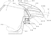
さらに、ロールバー32の頂部326とルーフ部材50の格納軌跡52との間の拡大した距離を、ロールバー32の頂部326を前側に寄せることに活用するのに加えて、ロールバー32の頂部326を高くすることにも活用してもよい。図11を参照して具体的に説明する。図11はロールバー構造に基づく乗員保護空間Sを示す車両の側面図であり、太線で単に車両前後方向の前方に寄せただけのロールバー32の頂部326及び乗員保護空間境界線328を示し、細線で前方に寄せつつ高くしたロールバー33の頂部336及び乗員保護空間境界線338を示す。
Further, in addition to utilizing the enlarged distance between the top 326 of the
ここで、車両1のフロントピラー16の頂部と、ロールバーの頂部とを結んだ線を、乗員保護空間境界線328、338として、該乗員保護空間境界線より下方の車室内の空間を乗員保護空間Sとする。図11に示されるように、ロールバー32の頂部326を高くすることによって、乗員保護空間Sを乗員保護空間境界線328から乗員保護空間境界線338まで角度αだけ増大させることができる。従って、ロールバー構造に基づく乗員保護性能を向上できる。
Here, the line connecting the top of the front pillar 16 of the
次に、図12を参照して、車両横転時におけるロールバーの作用開始のタイミングを早まることを説明する。図12は、ロールバー構造に基づく乗員保護空間Sを示す車両の正面図であり、太線でこの実施形態に係るロールバー構造30及び乗員保護空間境界線329を示し、細線で従来のロールバー構造70及びこのロールバー構造に基づく乗員保護空間境界線729を示す。
Next, with reference to FIG. 12, it will be described that the timing of starting the action of the roll bar at the time of vehicle rollover is advanced. FIG. 12 is a front view of a vehicle showing an occupant protection space S based on a roll bar structure. A thick line shows the
図12に示すように、ロールバーの両脚部をそれぞれシートバック22のヘッドレスト部222よりも車外側に配置しているため、両脚部を逆U字状に連結したロールバー32の頂部326は、シートバック22のヘッドレスト部222よりも車外側に位置することになる。このため、ロールバー32の頂部326は、従来のロールバー構造70の頂部726よりも図12中Aで示す距離だけ車外側に位置している。
As shown in FIG. 12, since both legs of the roll bar are arranged on the vehicle outer side than the headrest part 222 of the seat back 22, the top part 326 of the
これによって、乗員保護空間Sを乗員保護空間境界線729から乗員保護空間境界線329まで角度βだけ増大させることができる。つまり、乗員保護空間境界線729と乗員保護空間境界線329との間のなす角度βだけ、車両横転時にロールバーの作用開始を早めることができる。従って、ロールバー構造に基づく乗員保護性能を向上できる。
Accordingly, the passenger protection space S can be increased from the passenger protection space boundary line 729 to the passenger protection
次に、図13及び図14を参照して、シートバック22の後傾量を増大させることを説明する。図13は、最後方位置にあるシートのシートバックの後傾量を説明する平面図であり、図14は、最後方位置にあるシートのシートバックの後傾量を説明する側面図である。太線でこの実施形態に係るロールバー構造30及び最後方位置にあるシート20のシートバック22を最も後傾させた状態22aを示し、細線で従来のロールバー構造70及び最後方位置にあるシート20のシートバック22を最も後傾させた状態22a’を示す。
Next, referring to FIG. 13 and FIG. 14, it will be described how to increase the backward tilt amount of the seat back 22. FIG. 13 is a plan view for explaining the backward inclination amount of the seatback of the seat at the rearmost position, and FIG. 14 is a side view for explaining the backward inclination amount of the seatback of the seat at the rearmost position. A thick line shows the
図13及び図14に示すように、従来のロールバー構造70のロールバー72の頂部726は、シートバック22のヘッドレスト部222と正対する位置関係にある。このため、従来のロールバー構造70では、シート20の最後方位置においては、シートバック22のヘッドレスト部222とロールバー72の頂部726が接触する位置までしか、シートバック22を後傾させることができず、最も後傾した状態は22a’で示した状態に留まる。
As shown in FIGS. 13 and 14, the
対して、この実施形態に係るロールバー構造30においては、ロールバー32の頂部326は上述したようにシートバック22のヘッドレスト部222を車外側に避けてショルダー部224の上方に位置しているので、シートの最後方位置においてシートバック22を後傾させても、ロールバー32の頂部326とシートバック22のヘッドレスト部222が干渉することはなく、図14中22aで示した状態にまでシートバック22を後傾させることが可能となる。
On the other hand, in the
つまり、この実施形態に係るロールバー構造30では、ロールバー32の頂部326によってはシートバック22の後傾を制限されることはなく、図14に示すように角度γだけ従来のロールバー構造70よりもシートバック22の後傾量を増大させることができる。従って、シート20の最後方位置においてシートバック22の後傾量を増大させることができるため、より体型の大きな乗員に対しても適正な運転姿勢を提供することが可能となる。
In other words, in the
また、図3及び図4に示すように、この実施形態に係るロールバー構造30では、車外側脚部鉛直部322aはシートバック22の側方に位置しており、ショルダー部224まで上下に延びている。これによって、側面衝突時等にサイドパネル14が車体から受ける側突荷重がシート20に伝わるのに抗することができるため、シートバック22に直接に側突荷重が伝わることを回避できる。従って、ロールバー構造に基づく乗員保護性能を向上できる。
As shown in FIGS. 3 and 4, in the
また、左右一対のロールバー32はそれぞれフランジ40及び42を介してリヤデッキ10にボルトで強固に結合されており、且つ、両車内側脚部324はそれぞれクロスバー34に車内側脚部324を上下に貫通させると共に、クロスバー34の上壁部342及び下壁部344と溶接して接合されており、両車外側脚部322はそれぞれ下方連結部材38によってサイドパネル14と結合されている。
The pair of left and right roll bars 32 are firmly connected to the
さらに、クロスバー34は、左右一対のガセット36によってサイドパネル14に結合されている。つまり、左右一対のロールバー32は、クロスバー34によって結合されており、ガセット36と下方連結部材38を用いてさらにサイドパネル14に結合されている。
Further, the
これによって、車両の横転時にロールバー32が路面から受ける力がサイドパネル14とクロスバー34とに分散される。また、側面衝突時等にサイドパネル14が車体側方から受ける側突荷重が、ガセット36及び下方連結部材38を介して左右一対のロールバー32とクロスバー34とに分散される。その結果、車両の横転時にロールバー32に作用する力や側突荷重に対する、ロールバー構造30の耐力をより一層向上できる。
Thereby, the force that the
また、この実施形態に係るロールバー32は一端部の車外側脚部322をシートバック22の側方に配置して、他端部の車内側脚部324をシートバック22の後方に配置している。つまり、両脚部322及び324は、それぞれ車幅方向及び車両前後方向に位置をずらして配置しているため、車幅方向及び車両前後方向のいずれかの方向からの外力がロールバー32に作用しても、ロールバー32の車外側脚部322と車内側脚部324との間に効果的に支え合う関係が成立することになり、車幅方向及び車両前後方向のいずれの方向からの外力に対しても、常に効果的に抗することができる。
In addition, the
具体的に説明する。例えば、車両の横転時において車体の前後方向の外力がロールバー32に作用した場合、車外側脚部322はその断面形状が楕円であって長径が車両前後方向に平行になるように配置されているので、前後方向の外力に対して効果的に抗することができ、さらに、車外側脚部322の後方には車内側脚部324が配置されているため、車外側脚部322は前後方向の荷重に対して車内側脚部324によってその効果的姿勢を持って支持される。
This will be specifically described. For example, when an external force in the longitudinal direction of the vehicle body acts on the
同様に、車幅方向の外力がロールバー32に作用した場合、車内側脚部324はその断面形状が楕円であって長径が車幅方向に平行になるように配置されているので、車幅方向の外力に対して効果的に抗することができる。さらに、車内側脚部324の車外側には車外側脚部322が配置されているため、車内側脚部324は車幅方向の荷重に対して車外側脚部322によってその効果的姿勢をもって支持される。従って、ロールバー32は、車幅方向又は車両前後方向のいずれの方向からの外力に対しても、常に効果的に抗することができる。
Similarly, when an external force in the vehicle width direction acts on the
また、図3に示すように、ロールバー32の車外側脚部322は、シートバック22の側方に位置しているが、シートバック22のショルダー部224の高さから車内側へ折り曲げられ、車外側脚部傾斜部322bを形成している。これによって、シートバック22の側方の車外側脚部322とシートバック後方の車内側脚部324とを単に逆U字状に連結する場合に比して、ロールバー32の頂部326の車外側への突出しを低減することができる。
Further, as shown in FIG. 3, the vehicle outer
これによって、ルーフの側部形状とロールバー32との隙間を拡大することができるため、ルーフの側部形状の車内側への絞込みが可能となり、ルーフの側部形状のデザイン自由度を向上できる。
As a result, the gap between the side shape of the roof and the
また、ロールバー32の車外側脚部322は、下方連結部材38のクランプ386を介してサイドパネル14に結合されている。これによって、サイドパネルに設けられた取り付け孔(図示せず)のロールバーの車外側脚部322に対する上下位置がずれた場合であっても、クランプ部386をロールバー32の車外側脚部鉛直部322aに沿って移動させることによって、組み付け位置のずれを吸収することができる。従って、下方連結部材38の組み付け性を向上できる。
Further, the vehicle outer
また、図6に示すように、この実施形態に係るロールバー構造30では、楕円断面のロールバー32を採用している。ロールバー32の断面を楕円にすることによって、省スペース化を図りつつ丸パイプと同じ強度を確保している。具体的には、車外側脚部322は車幅方向に薄くなるよう配置されているため、シートバック22又はサイドパネル14の車幅方向の寸法を低減することなく、シートバック22の側方にロールバー32の車外側脚部322を配置することができる。
Moreover, as shown in FIG. 6, the
また、車内側脚部324は車両前後方向に薄くなるように配置されているため、シートバック22の後方に配置しても、ルーフ部材格納部の車両前後方向の寸法を拡大できる。このため、ルーフ部材格納部をさらに車両前後方向の前方に寄せることができるため、シートの前後移動量を確保しながら、車室の前後寸法の低減を可能とする。 Further, since the vehicle inner leg portion 324 is disposed so as to be thin in the vehicle front-rear direction, the size of the roof member storage portion in the vehicle front-rear direction can be increased even if it is disposed behind the seat back 22. For this reason, since the roof member storage portion can be further moved forward in the vehicle front-rear direction, the front-rear dimension of the passenger compartment can be reduced while ensuring the amount of seat front-rear movement.
また、図14を参照して、駐車場でのシートバック22を後傾させての休憩時には、着座者の顔がロールバー32の車外側脚部322により、車両側方視から部分的に隠ぺいされるので、着座者が感ずる車外の眩しさや、車外からの覗かれ感を軽減することができる。
Referring to FIG. 14, when the seat back 22 is tilted backward in the parking lot, the seated person's face is partially concealed from the vehicle side view by the vehicle
次に、図15を参照して、オープンカーの上部車体構造の他の実施形態について説明する。図15は本発明に係るオープンカーの上部車体構造の他の実施形態を示す斜視図である。 Next, with reference to FIG. 15, another embodiment of the upper vehicle body structure of an open car will be described. FIG. 15 is a perspective view showing another embodiment of the upper body structure of the open car according to the present invention.
上記の実施形態においては、ロールバー32を楕円断面のパイプを採用しているが、図15に示すように、サイドパネル14とシートバック22との間の空間を確保(例えばシートバックの車幅方向寸法を低減する)することによって、丸断面のパイプを採用できる。これによって、ロールバー32をより一層、容易に形成できる。
In the above embodiment, the
さらに、上記の実施形態においては、ロールバー32の車内側脚部がクロスバー34を上下に延びるように貫通して、その一端部がフランジ42を介してリヤデッキ10にボルトで固定されているが、図15に示すように、クロスバー34の下壁部344から少し突出す位置に留めてリヤデッキに固定しなくてもよい。これによって、クロスバー34とリヤデッキ10との間に小物入れ用の空間を設けたり、ルーフ部材格納部Rを増大したりすることができる。
Furthermore, in the above embodiment, the inner leg portion of the
なお、本発明は、以上の実施形態に示すものに限らず、特許請求の範囲に記載された本発明の精神および範囲から逸脱することなく、各種変形および変更を行うことも可能である。 The present invention is not limited to the embodiment described above, and various modifications and changes can be made without departing from the spirit and scope of the present invention described in the claims.
以上のように、本発明に係るオープンカーの上部車体構造によれば、シートの所望の前後移動量を確保しながら、車室の前後寸法を短縮することが可能となる。さらに、ロールバー構造に基づく乗員保護空間を増大させると共にロールバーの耐力を向上させることができる。従って、本発明は、オープンカーの上部車体構造を製造し或いは使用する産業分野において好適に利用される可能性がある。 As described above, according to the upper car body structure of the open car according to the present invention, it is possible to shorten the front-rear dimension of the passenger compartment while securing a desired front-rear movement amount of the seat. Furthermore, the occupant protection space based on the roll bar structure can be increased and the strength of the roll bar can be improved. Therefore, the present invention may be suitably used in the industrial field in which the upper body structure of an open car is manufactured or used.
1 車両
14 サイドパネル
15 フロントピラー
20 シート
22 シートバック
222 ヘッドレスト部
224 ショルダー部
30 ロールバー構造
32 ロールバー
322 車外側脚部
324 車内側脚部
326 頂部
328、329 乗員保護空間境界線
34 クロスバー
36 ガセット
38 下方連結部材
50 ルーフ部材
52 ルーフ部材格納軌跡
R ルーフ部材格納部
S 乗員保護空間
DESCRIPTION OF
Claims (4)
前記ルーフ部材格納部の車両前後方向の前方に、
前記シートを構成するシートバックの車外側の側方に位置する車外側脚部と、
前記シートバックの車両前後方向の後方において該シートバックの車幅方向の中央よりも車外側に位置する車内側脚部と、を有する逆U字状のロールバーを左右に配置し、
前記ロールバーの上部は、車両前後方向の前方かつ車内側に折れ曲がっていることを特徴とする、オープンカーの上部車体構造。 In the upper car body structure of an open car in which a roof member storage portion is provided on a rear deck behind the seat in the passenger compartment, and the roof member is rotationally stored in the storage portion.
In front of the vehicle front-rear direction of the roof member storage portion,
A vehicle outer leg located on the vehicle outer side of the seat back constituting the seat;
An inverted U-shaped roll bar having left and right vehicle inner side legs positioned on the vehicle outer side than the center in the vehicle width direction of the seat back at the rear of the seat back in the vehicle front-rear direction ;
The upper body structure of an open car, wherein the upper portion of the roll bar is bent forward and inward of the vehicle in the longitudinal direction .
Priority Applications (1)
| Application Number | Priority Date | Filing Date | Title |
|---|---|---|---|
| JP2012228241A JP5920162B2 (en) | 2012-10-15 | 2012-10-15 | Upper car body structure of open car |
Applications Claiming Priority (1)
| Application Number | Priority Date | Filing Date | Title |
|---|---|---|---|
| JP2012228241A JP5920162B2 (en) | 2012-10-15 | 2012-10-15 | Upper car body structure of open car |
Publications (2)
| Publication Number | Publication Date |
|---|---|
| JP2014080073A JP2014080073A (en) | 2014-05-08 |
| JP5920162B2 true JP5920162B2 (en) | 2016-05-18 |
Family
ID=50784698
Family Applications (1)
| Application Number | Title | Priority Date | Filing Date |
|---|---|---|---|
| JP2012228241A Expired - Fee Related JP5920162B2 (en) | 2012-10-15 | 2012-10-15 | Upper car body structure of open car |
Country Status (1)
| Country | Link |
|---|---|
| JP (1) | JP5920162B2 (en) |
Family Cites Families (2)
| Publication number | Priority date | Publication date | Assignee | Title |
|---|---|---|---|---|
| DE4108189C1 (en) * | 1991-03-14 | 1992-10-01 | Mercedes-Benz Aktiengesellschaft, 7000 Stuttgart, De | |
| JP4370508B2 (en) * | 2003-12-24 | 2009-11-25 | マツダ株式会社 | Roll bar structure of vehicle |
-
2012
- 2012-10-15 JP JP2012228241A patent/JP5920162B2/en not_active Expired - Fee Related
Also Published As
| Publication number | Publication date |
|---|---|
| JP2014080073A (en) | 2014-05-08 |
Similar Documents
| Publication | Publication Date | Title |
|---|---|---|
| JP4621982B2 (en) | Lower body structure | |
| JP4654917B2 (en) | Car body rear structure | |
| JP5891827B2 (en) | Lower body structure of the car body | |
| JP4752411B2 (en) | Body frame structure | |
| JP2007125974A (en) | Lower structure of vehicle body | |
| JP6694593B2 (en) | Cab bottom structure | |
| JP6098649B2 (en) | Auto body structure | |
| JP6084503B2 (en) | Vehicle lower body structure | |
| JP5920162B2 (en) | Upper car body structure of open car | |
| JP6152789B2 (en) | Vehicle seat back bar structure | |
| JP2014040209A (en) | Vehicle body lower structure of vehicle | |
| JP5509265B2 (en) | Body front structure | |
| JP2008302911A (en) | Vehicle body structure | |
| JP2009012634A (en) | Body structure for vehicle | |
| JP5515956B2 (en) | Upper body structure of the vehicle | |
| JP4507871B2 (en) | Open car rear body structure | |
| JP5831130B2 (en) | Front pillar structure | |
| JP6187210B2 (en) | Vehicle seat back bar structure | |
| JP2008110636A (en) | Lower part vehicle body structure for vehicle | |
| JP6152792B2 (en) | Vehicle seat back bar structure | |
| JP4453005B2 (en) | Seat bracket mounting structure | |
| JP6152790B2 (en) | Vehicle seat back bar structure | |
| JP2011131661A (en) | Upper part vehicle body structure of vehicle | |
| JP4766386B2 (en) | Rear structure of roof-open vehicle | |
| JP2018062255A (en) | Side body structure for vehicle |
Legal Events
| Date | Code | Title | Description |
|---|---|---|---|
| A621 | Written request for application examination |
Free format text: JAPANESE INTERMEDIATE CODE: A621 Effective date: 20150312 |
|
| A977 | Report on retrieval |
Free format text: JAPANESE INTERMEDIATE CODE: A971007 Effective date: 20151217 |
|
| A131 | Notification of reasons for refusal |
Free format text: JAPANESE INTERMEDIATE CODE: A131 Effective date: 20151222 |
|
| A521 | Request for written amendment filed |
Free format text: JAPANESE INTERMEDIATE CODE: A523 Effective date: 20160127 |
|
| TRDD | Decision of grant or rejection written | ||
| A01 | Written decision to grant a patent or to grant a registration (utility model) |
Free format text: JAPANESE INTERMEDIATE CODE: A01 Effective date: 20160315 |
|
| A61 | First payment of annual fees (during grant procedure) |
Free format text: JAPANESE INTERMEDIATE CODE: A61 Effective date: 20160328 |
|
| R150 | Certificate of patent or registration of utility model |
Ref document number: 5920162 Country of ref document: JP Free format text: JAPANESE INTERMEDIATE CODE: R150 |
|
| LAPS | Cancellation because of no payment of annual fees |