JP5908994B2 - SOUND GENERATOR, SOUND GENERATOR, AND ELECTRONIC DEVICE - Google Patents
SOUND GENERATOR, SOUND GENERATOR, AND ELECTRONIC DEVICE Download PDFInfo
- Publication number
- JP5908994B2 JP5908994B2 JP2014552953A JP2014552953A JP5908994B2 JP 5908994 B2 JP5908994 B2 JP 5908994B2 JP 2014552953 A JP2014552953 A JP 2014552953A JP 2014552953 A JP2014552953 A JP 2014552953A JP 5908994 B2 JP5908994 B2 JP 5908994B2
- Authority
- JP
- Japan
- Prior art keywords
- exciter
- frame
- terminal
- sound generator
- vibrating body
- Prior art date
- Legal status (The legal status is an assumption and is not a legal conclusion. Google has not performed a legal analysis and makes no representation as to the accuracy of the status listed.)
- Expired - Fee Related
Links
Images


Classifications
-
- H—ELECTRICITY
- H04—ELECTRIC COMMUNICATION TECHNIQUE
- H04R—LOUDSPEAKERS, MICROPHONES, GRAMOPHONE PICK-UPS OR LIKE ACOUSTIC ELECTROMECHANICAL TRANSDUCERS; ELECTRIC HEARING AIDS; PUBLIC ADDRESS SYSTEMS
- H04R1/00—Details of transducers, loudspeakers or microphones
- H04R1/02—Casings; Cabinets ; Supports therefor; Mountings therein
-
- H—ELECTRICITY
- H04—ELECTRIC COMMUNICATION TECHNIQUE
- H04B—TRANSMISSION
- H04B1/00—Details of transmission systems, not covered by a single one of groups H04B3/00 - H04B13/00; Details of transmission systems not characterised by the medium used for transmission
- H04B1/38—Transceivers, i.e. devices in which transmitter and receiver form a structural unit and in which at least one part is used for functions of transmitting and receiving
-
- H—ELECTRICITY
- H04—ELECTRIC COMMUNICATION TECHNIQUE
- H04R—LOUDSPEAKERS, MICROPHONES, GRAMOPHONE PICK-UPS OR LIKE ACOUSTIC ELECTROMECHANICAL TRANSDUCERS; ELECTRIC HEARING AIDS; PUBLIC ADDRESS SYSTEMS
- H04R17/00—Piezoelectric transducers; Electrostrictive transducers
-
- H—ELECTRICITY
- H04—ELECTRIC COMMUNICATION TECHNIQUE
- H04R—LOUDSPEAKERS, MICROPHONES, GRAMOPHONE PICK-UPS OR LIKE ACOUSTIC ELECTROMECHANICAL TRANSDUCERS; ELECTRIC HEARING AIDS; PUBLIC ADDRESS SYSTEMS
- H04R3/00—Circuits for transducers
-
- H—ELECTRICITY
- H04—ELECTRIC COMMUNICATION TECHNIQUE
- H04R—LOUDSPEAKERS, MICROPHONES, GRAMOPHONE PICK-UPS OR LIKE ACOUSTIC ELECTROMECHANICAL TRANSDUCERS; ELECTRIC HEARING AIDS; PUBLIC ADDRESS SYSTEMS
- H04R1/00—Details of transducers, loudspeakers or microphones
- H04R1/06—Arranging circuit leads; Relieving strain on circuit leads
-
- H—ELECTRICITY
- H04—ELECTRIC COMMUNICATION TECHNIQUE
- H04R—LOUDSPEAKERS, MICROPHONES, GRAMOPHONE PICK-UPS OR LIKE ACOUSTIC ELECTROMECHANICAL TRANSDUCERS; ELECTRIC HEARING AIDS; PUBLIC ADDRESS SYSTEMS
- H04R7/00—Diaphragms for electromechanical transducers; Cones
- H04R7/02—Diaphragms for electromechanical transducers; Cones characterised by the construction
- H04R7/04—Plane diaphragms
- H04R7/045—Plane diaphragms using the distributed mode principle, i.e. whereby the acoustic radiation is emanated from uniformly distributed free bending wave vibration induced in a stiff panel and not from pistonic motion
Landscapes
- Engineering & Computer Science (AREA)
- Signal Processing (AREA)
- Physics & Mathematics (AREA)
- Acoustics & Sound (AREA)
- Computer Networks & Wireless Communication (AREA)
- Piezo-Electric Transducers For Audible Bands (AREA)
- Diaphragms For Electromechanical Transducers (AREA)
- Details Of Audible-Bandwidth Transducers (AREA)
- Telephone Function (AREA)
Description
開示の実施形態は、音響発生器、音響発生装置および電子機器に関する。 Embodiments of the disclosure relate to a sound generator, a sound generation device, and an electronic apparatus.
従来、圧電素子を用いた音響発生器が知られている(たとえば、特許文献1参照)。かかる音響発生器は、振動板に取り付けた圧電素子に電圧を印加して振動させることによって振動板を振動させ、かかる振動の共振を積極的に利用することで音響を出力するものである。 Conventionally, an acoustic generator using a piezoelectric element is known (see, for example, Patent Document 1). Such an acoustic generator is configured to vibrate a diaphragm by applying a voltage to a piezoelectric element attached to the diaphragm to vibrate, and to output sound by actively utilizing resonance of the vibration.
また、かかる音響発生器は、振動板に樹脂フィルムなどの薄膜を用いることができるため、一般的な電磁式スピーカなどに比べて薄型かつ軽量に構成することが可能である。 In addition, since such a sound generator can use a thin film such as a resin film for the diaphragm, it can be made thinner and lighter than a general electromagnetic speaker.
なお、振動板に薄膜を用いる場合、薄膜は、優れた音響変換効率を得られるように、たとえば一対の枠部材によって厚み方向から挟持されることによって均一に張力をかけられた状態で支持されることが求められる。 In addition, when using a thin film for a diaphragm, the thin film is supported in a state in which a uniform tension is applied, for example, by being sandwiched from a thickness direction by a pair of frame members so as to obtain excellent acoustic conversion efficiency. Is required.
しかしながら、上記した従来の音響発生器は、均一に張力がかけられた振動板の共振を積極的に利用するが故に、音圧の周波数特性においてピーク(周囲よりも音圧が高い部分)およびディップ(周囲よりも音圧が低い部分)が生じやすく、良質な音質を得にくいという問題があった。 However, the conventional acoustic generator described above actively uses the resonance of the diaphragm that is uniformly tensioned, and therefore, in the frequency characteristics of the sound pressure, the peak (the portion where the sound pressure is higher than the surroundings) and the dip There is a problem that high quality sound quality is difficult to obtain due to the fact that the sound pressure is lower than the surrounding area.
実施形態の一態様は、上記に鑑みてなされたものであって、良好な音圧の周波数特性を得ることができる音響発生器、音響発生装置および電子機器を提供することを目的とする。 One embodiment of the present invention has been made in view of the above, and an object thereof is to provide an acoustic generator, an acoustic generator, and an electronic apparatus that can obtain a favorable frequency characteristic of sound pressure.
実施形態の一態様に係る音響発生器は、励振器と、振動体と、枠体と、導線とを備える。前記励振器は、電気信号が入力されて振動する。前記振動体は、前記励振器が取り付けられており、該励振器の振動によって該励振器とともに振動する。前記枠体は、前記振動体の外周部に設けられ、該振動体を扁平に支持する。前記導線は、前記励振器に接続され、該励振器へ電気信号を入力する。また、前記枠体は前記導線への接続点となる複数個の端子を有しており、該複数個の端子は、当該複数個の端子の少なくとも2つを結ぶ線が平面視で前記枠体の辺と非平行となるように設けられている。 An acoustic generator according to an aspect of an embodiment includes an exciter, a vibrating body, a frame, and a conductive wire. The exciter vibrates upon receiving an electrical signal. The vibrator is attached with the exciter, and vibrates with the exciter due to vibration of the exciter. The frame body is provided on an outer peripheral portion of the vibrating body, the vibrating body Bian earnestly support. The conducting wire is connected to the exciter and inputs an electrical signal to the exciter. Furthermore, the frame has a plurality of terminals to which the connection point of the previous SL conductors, several terminals plurality, the frame line connecting at least two of said plurality of terminals in a plan view It is provided so as to be non-parallel to the side of the body .
実施形態の一態様によれば、良好な音圧の周波数特性を得ることができる。 According to one aspect of the embodiment, a favorable sound pressure frequency characteristic can be obtained.
以下、添付図面を参照して、本願の開示する音響発生器、音響発生装置および電子機器の実施形態を詳細に説明する。なお、以下に示す実施形態によりこの発明が限定されるものではない。 Hereinafter, embodiments of a sound generator, a sound generator, and an electronic device disclosed in the present application will be described in detail with reference to the accompanying drawings. In addition, this invention is not limited by embodiment shown below.
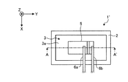
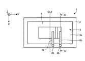
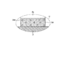
まず、実施形態に係る音響発生器1の説明に先立って、基本的な音響発生器1’の概略構成について、図1A〜図1Cを用いて説明する。図1Aは、音響発生器1’の概略構成を示す模式的な平面図であり、図1Bは、図1AのA−A’線断面図(その1)であり、図1Cは、図1AのA−A’線断面図(その2)である。
First, prior to the description of the
なお、説明を分かりやすくするために、図1A〜図1Cには、鉛直上向きを正方向とし、鉛直下向きを負方向とするZ軸を含む3次元の直交座標系を図示している。かかる直交座標系は、後述の説明に用いる他の図面でも示す場合がある。 For easy understanding, FIGS. 1A to 1C illustrate a three-dimensional orthogonal coordinate system including a Z-axis in which a vertical upward direction is a positive direction and a vertical downward direction is a negative direction. Such an orthogonal coordinate system may also be shown in other drawings used in the following description.
また、図1Aにおいては、樹脂層7(後述)の図示を省略している。また、説明を分かりやすくするために、図1Bおよび図1Cは、音響発生器1’を厚み方向(Z軸方向)に大きく誇張して示している。
Moreover, in FIG. 1A, illustration of the resin layer 7 (described later) is omitted. For easy understanding, FIG. 1B and FIG. 1C show the
図1Aに示すように、音響発生器1’は、枠体2と、振動板3と、圧電素子5と、リード線6a、6bとを備える。なお、図1Aに示すように、以下の説明では、圧電素子5が1個である場合を例示するが、圧電素子5の個数を限定するものではない。
As shown in FIG. 1A, the acoustic generator 1 'includes a
また、図1Bに一例として示すように、枠体2は、振動板3の周縁部で振動板3を支持する支持体として機能する。振動板3は、板状やフィルム状の形状を有しており、その周縁部が枠体2に固定され、枠体2の枠内において均一に張力をかけられた状態で略扁平に支持される。
Further, as illustrated in FIG. 1B as an example, the
また、図1Cに示す一例では、枠体2は、矩形の枠状で同一形状を有する2枚の枠部材によって構成されており、振動板3の周縁部を挟み込んで振動板3を支持する支持体として機能する。振動板3は、板状やフィルム状の形状を有しており、その周縁部が枠体2に挟み込まれて固定され、枠体2の枠内において均一に張力をかけられた状態で略扁平に支持される。
In the example shown in FIG. 1C, the
この場合、2枚の枠部材で振動板3を挟むことで、振動板3の張りを安定させることができるので、音響発生器1’の周波数特性を長期間変動しない耐久性のあるものとすることができるからさらに良い。
In this case, since the tension of the
なお、振動板3のうち枠体2の内周よりも内側の部分、すなわち、振動板3のうち枠体2に挟み込まれておらず自由に振動することができる部分を振動体3aとする。すなわち、振動体3aは、枠体2の枠内において略矩形状をなす部分である。
A portion of the
また、振動板3は、樹脂や金属等の種々の材料を用いて形成することができる。たとえば、厚さ10〜200μmのポリエチレン、ポリイミド、ポリプロピレン等の樹脂フィルムで振動板3を構成することができる。樹脂フィルムは金属板などに比べて弾性率および機械的なQ値の低い材料であるため、振動板3を樹脂フィルムにより構成することで、振動板3を大きな振幅で屈曲振動させ、音圧の周波数特性における共振ピークの幅を広く、高さを低くして共振ピークとディップとの差を低減することができる。なお、金属と樹脂との複合体を振動板3として用いてもよい。
The
また、枠体2の厚みや材質などについても、特に限定されるものではなく、金属や樹脂など種々の材料を用いて形成することができる。たとえば、機械的強度および耐食性に優れるという理由から、厚さ100〜1000μmのステンレス製のものなどを枠体2として好適に用いることができる。
Further, the thickness and material of the
なお、図1Aには、その内側の領域の形状が略矩形状である枠体2を示しているが、平行四辺形、台形および正n角形といった多角形であってもよい。本実施形態では、図1Aに示すように、略矩形状であるものとする。
Although FIG. 1A shows the
圧電素子5は、振動体3aの表面に貼り付けられるなどして設けられ、電圧の印加を受けて振動することによって振動体3aを励振する励振器である。
The
かかる圧電素子5は、図1Bまたは図1Cに示すように、たとえば、4層のセラミックスからなる圧電体層5a、5b、5c、5dと、3層の内部電極層5eが交互に積層された積層体と、かかる積層体の上面および下面に形成された表面電極層5f、5gと、内部電極層5eが露出した側面に形成された外部電極5h、5jとを備える。また、外部電極5h、5jには、リード線6a、6bが接続される。リード線6a、6bは、外部から電気信号を入力する導線である。
As shown in FIG. 1B or FIG. 1C, the
なお、圧電素子5は板状であり、上面側および下面側の主面が長方形状または正方形状といった多角形をなしている。また、圧電体層5a、5b、5c、5dは、図1Bまたは図1Cに矢印で示すように分極されている。すなわち、ある瞬間に加えられる電界の向きに対する分極の向きが厚み方向(図のZ軸方向)における一方側と他方側とで逆転するように分極されている。
The
そして、リード線6a、6bを介して圧電素子5に電圧が印加されると、たとえば、ある瞬間において、振動体3aに接着された側の圧電体層5c、5dは縮み、圧電素子5の上面側の圧電体層5a、5bは延びるように変形する。よって、圧電素子5に交流信号を与えることにより、圧電素子5が屈曲振動し、振動体3aに屈曲振動を与えることができる。
When a voltage is applied to the
このように、圧電素子5の上面側の圧電体層5a、5bと下面側の圧電体層5c、5dとが、相反する伸縮挙動を示し、その結果、圧電素子5がバイモルフ型の屈曲振動をすることにより、振動体3aに一定の振動を与えて音を発生させることができる。圧電素子5がバイモルフ型の積層型圧電振動素子であり、圧電素子5自体が単独で屈曲振動することから、振動体3aの材質によらず、例えば柔らかい振動体3aであっても強い振動を発生させることができ、少数の圧電素子5により充分な音圧を得ることができる。
As described above, the
また、圧電素子5は、その主面が、振動体3aの主面と、エポキシ系樹脂等の接着剤により接合されている。
In addition, the main surface of the
なお、圧電体層5a、5b、5cおよび5dを構成する材料には、チタン酸ジルコン酸鉛(lead zirconate titanate)、Bi層状化合物、タングステンブロンズ構造化合物等の非鉛系圧電体材料等、従来から用いられている圧電セラミックスを用いることができる。
The materials constituting the
また、内部電極層5eの材料としては、種々の金属材料を用いることができる。たとえば、銀とパラジウムとからなる金属成分と、圧電体層5a、5b、5c、5dを構成するセラミック成分とを含有した場合、圧電体層5a、5b、5c、5dと内部電極層5eとの熱膨張差による応力を低減することができるので、積層不良のない圧電素子5を得ることができる。
Various metal materials can be used as the material of the
また、表面電極層5f、5gと外部電極5h、5jは、金属、例えば銀などを主成分とする。また、ガラス成分を含有しても良い。ガラス成分を含有させることによって、圧電体層5a、5b、5c、5dや内部電極層5eと、表面電極層5f、5gまたは外部電極5h、5jとの間に強固な密着力を得ることができる。ガラス成分の含有量は、たとえば20体積%以下とすればよい。
The
また、リード線6a、6bは、導線の一例であり、一端部が圧電素子5に接続され、圧電素子5へ電気信号を入力する。かかるリード線6a、6bは、種々の金属材料を用いて形成することができる。たとえば、銅またはアルミニウムなどの金属箔を樹脂フィルムで挟んだフレキシブル配線を用いてリード線6a、6bを構成すると、圧電素子5の低背化を図ることができる。
The
また、図1Bまたは図1Cに示すように、音響発生器1’は、枠体2の枠内において圧電素子5および振動体3aの表面に被せるように配置されて、振動体3aおよび圧電素子5と一体化された樹脂層7をさらに備える。
Further, as shown in FIG. 1B or 1C, the
樹脂層7は、たとえば、アクリル系樹脂を用いてヤング率が1MPa〜1GPaの範囲程度となるように形成されることが好ましい。なお、かかる樹脂層7に圧電素子5を埋設することで適度なダンパー効果を誘発させることができるので、共振現象を抑制して、音圧の周波数特性におけるピークやディップを小さく抑えることができる。
The
また、図1Bまたは図1Cには、樹脂層7が、枠体2と同じ高さとなるように形成された状態を示しているが、樹脂層7が枠体2の高さよりも高くなるように形成されてもよい。逆に、樹脂層7は、必ずしも圧電素子5および振動体3aの表面に被せるように配置されていなくてもよく、圧電素子5と、この圧電素子5が配置されている側の振動体3aの表面の少なくとも一部とが樹脂層7により被覆されていればよい。
1B or 1C shows a state in which the
このように、振動体3a、圧電素子5および樹脂層7は一体化されており、一体的に振動するいわば複合振動体を構成している。
As described above, the vibrating
なお、図1Bまたは図1Cでは、圧電素子5として、バイモルフ型の積層型圧電素子を例に挙げたが、これに限られるものではなく、たとえば、伸縮する圧電素子5を振動体3aに貼り付けたユニモルフ型であっても構わない。
In FIG. 1B or 1C, the bimorph multilayer piezoelectric element is taken as an example of the
ところで、図1A〜図1Cに示したように、振動体3aは、枠体2の枠内において均一に張力をかけられた状態で略扁平に支持されている。このような場合、圧電素子5の振動に誘導された共振に起因するピークディップや歪みが生じるために、特定の周波数において音圧が急激に変化し、音圧の周波数特性が平坦化しづらい。
By the way, as shown in FIGS. 1A to 1C, the vibrating
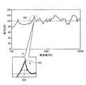
かかる点を、図2に図示する。図2は、音圧の周波数特性の一例を示す図である。図1Aの説明で既に述べたように、振動体3aは、枠体2の枠内において均一に張力をかけられた状態で略扁平に支持されている。
This point is illustrated in FIG. FIG. 2 is a diagram illustrating an example of frequency characteristics of sound pressure. As already described in the description of FIG. 1A, the vibrating
しかしながら、このような場合、振動体3aの共振によって特定の周波数にピークが集中して縮退するため、図2に示すように、周波数領域全体にわたって急峻なピークやディップが散在して生じやすい。
However, in such a case, since the peak concentrates on a specific frequency due to resonance of the vibrating
一例として、図2において破線の閉曲線PDで囲んで示した部分に着目する。このようなピークが生じる場合、周波数によって音圧にばらつきが生じることとなるため、良好な音質を得にくくなる。 As an example, attention is paid to a portion surrounded by a broken closed curve PD in FIG. When such a peak occurs, the sound pressure varies depending on the frequency, making it difficult to obtain good sound quality.
こうした場合、図2に示すように、ピークPの高さを下げ(図中の矢印201参照)、かつ、ピーク幅を広げ(図中の矢印202参照)、ピークPやディップ(図示略)を小さくするような方策をとることが有効である。
In such a case, as shown in FIG. 2, the height of the peak P is lowered (see the
ここで、枠体2に着目する。枠体2は、上述のように、振動体3aへ均一に張力をかけつつ支持する支持体であるが、振動体3aが振動する際には、その振動体3aの共振に誘導されてやはり枠体2自体も振動している。また、枠体2は、振動体3aに対して反射波を返している。したがって、枠体2は、上述の、一体的に振動する複合振動体の構成要素の一つとみなすことができる。
Here, focus on the
そこで、本実施形態では、まず枠体2の主面に対し、外部からリード線6a、6bへの接続点となる「端子」を設けることによってかかる「端子」の周囲で振動波を乱すことで、枠体2から振動体3aへ返る反射波を乱すこととした。そして、これにより、共振周波数を部分的に揃わなくさせることで共振モードの縮退を解いて分散させ、ピークPの高さを下げるとともに、ピーク幅を広げることとした。
Therefore, in the present embodiment, by first providing “terminals” as connection points to the
さらに、本実施形態では、かかる「端子」を枠体2の辺の中央を避けた部位に設けることによって、上述の複合振動体全体の形状に非対称性をもたせ、反射波の対称性を低下させることとした。そして、これにより、やはり共振周波数を部分的に揃わなくさせることでピークPの高さを下げるとともに、ピーク幅を広げることとした。
Further, in the present embodiment, by providing such “terminal” at a portion that avoids the center of the side of the
また、枠体2の対称性を崩すことにより、枠体2の縮退した振動モードを複数の振動モードに分散させることができ、枠体2の共振周波数における音圧のピーク形状をなだらかにできる。結果として、複合振動体全体の音圧の周波数特性における共振ピークとディップの差を低減して音圧の周波数変動を可及的に抑制でき、音質の向上を図ることができる。特に、「端子」へ電気信号が入力された場合には、「端子」の近傍において枠体2の温度が変化して膨張収縮が起こり枠体2に歪みが生じるため、縮退した振動モードをさらに分散することができる。
Further, by breaking the symmetry of the
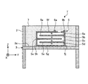
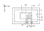
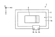
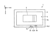
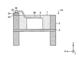
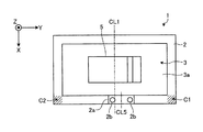
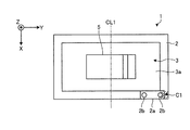
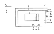
以下、実施形態に係る音響発生器1について、具体的に図3A〜図5Jを用いて順次説明する。まず、図3Aは、実施形態に係る音響発生器1の構成の一例を示す模式的な平面図(その1)である。また、図3Bは、実施形態に係る音響発生器1の構成の一例を示す模式的な平面図(その2)である。また、図3Cは、図3BのB−B’線断面図である。
Hereinafter, the
なお、図3Aおよび図3Bの模式的な平面図を含め、以下に示す各図面では、説明の便宜上、図1Aと同様に樹脂層7の図示を省略する場合がある。
In addition, in each drawing shown below including the schematic plan view of FIG. 3A and FIG. 3B, illustration of the
図3Aに示すように、音響発生器1は、図1A〜図1Cに示した音響発生器1’に加えて、端子2bを備える。端子2bは、外部からの接続点となるいわゆる電極ターミナルであり、枠体2に少なくとも1つ以上設けられる。なお、図3Aには、枠体2に複数個(ここでは2個)の端子2bが設けられている場合を例示している。これにより、縮退した振動モードをさらに分散させることができ、より共振周波数における音圧のピーク形状をなだらかにできる。
As shown in FIG. 3A, the
また、同じく複数個の端子2bが設けられる場合、少なくとも1つの端子2bの極性がその他の端子2bの極性と異なることがより効果的である。すなわち、端子2bの極性が異なれば、端子2bそれぞれに異なった信号成分があるので、端子2bそれぞれの周囲の温度上昇が異なることとなる。したがって、伝播する振動波をさらに乱すことができるので、共振周波数を部分的に揃わなくさせることができる。
Similarly, when a plurality of
また、端子2bは、リード線6a、6bによって、圧電素子5と接続されるので、リード線6a、6bを介して圧電素子5の周囲の振動を拾うことができる。これにより、さらに端子2bの周囲で振動波を効果的に乱すことができる。
Further, since the terminal 2b is connected to the
ここで、端子2bは、たとえば、中間層2dを介して枠体2に設けられているのが好ましい。また、枠体2が金属材料を用いて形成されている場合には、端子2bは、たとえば、接続点となる部分が金属材料で、枠体2と接する部分が絶縁体でそれぞれ構成されて、中間層2dを介して枠体2に設けられる。
Here, it is preferable that the terminal 2b is provided in the
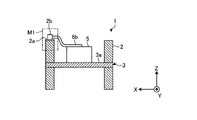
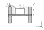
かかる点について図3Dおよび図3Eを参照して説明する。図3Dは、図3AのC−C’線断面図であり、図3Eは、図3Dに示すH部の拡大図である。 This point will be described with reference to FIGS. 3D and 3E. 3D is a cross-sectional view taken along line C-C ′ of FIG. 3A, and FIG. 3E is an enlarged view of a portion H illustrated in FIG. 3D.
図3Dに示すように、端子2bは、枠体2の主面に対して中間層2dを介して固定されている。かかる端子2bには、リード線6a、6bの他端部が接続される。
As illustrated in FIG. 3D, the
中間層2dは、たとえば接着剤であり、枠体2よりもヤング率(E)が低い部材である。このように、第1の実施形態では、端子2bが、枠体2よりもヤング率(E)が低い中間層2dを介して枠体2に固定される。ヤング率(E)が低い材料は通常、機械的Q値が小さい、すなわち機械的損失が大きいため、このような中間層2dを設けることにより、枠体2の振動が中間層2dによって吸収され、端子2bが設けられた部分において枠体2の振動をより大きく乱すことができるため、音圧をより平坦化することができ、音質の更なる向上を図ることができる。また、枠体2の振動が端子2bに伝わる際に減衰されるので、端子2bの振動による劣化が低減し、耐久性が向上するという効果も得られる。
The
ここで、枠体2および端子2bがともに金属で構成される場合、中間層2dは、絶縁性を有することが望ましい。このように、絶縁性を有する中間層2dを介して端子2bを枠体2へ固定することで、枠体2と端子2bとの絶縁性を確保しつつ、枠体2の振動をより大きく乱すことができる。
Here, when both the
なお、中間層2dは、たとえば、接着剤、絶縁層、接着剤の3層構造であってもよい。また、端子2bの枠体2と接する部分または枠体2が樹脂等の絶縁体で構成される場合、中間層2dは、必ずしも絶縁性を有することを要しない。
The
また、図3Eに示すように、中間層2dは、内部に気孔2da、いわゆるボイドを含んでいることが好ましい。
As shown in FIG. 3E, the
このように、中間層2dに気孔2daを設けることで、中間層2d内にヤング率の異なる領域が点在するようになることから、その領域において共振のエネルギーが吸収され、共振周波数における音圧のピーク形状がなだらかになる。この結果、音圧の周波数特性における共振ピークとディップとの差が低減され周波数特性を平坦化することができる。なお、気孔2daは、中間層2d内のあらゆる方向からの応力や共振のエネルギーを吸収しやすくするために球状であることが好ましい。
Thus, by providing the pores 2da in the
また、端子2bは、枠体2の外側面や、振動体3aに対して圧電素子5が設けられる側およびそれと反対側の枠体2の主面のいずれに固定されてもよいが、特に、圧電素子5が設けられる側の枠体2の主面に固定されることが好ましい。これにより、圧電素子5から発生して空中を伝わる振動に起因して生じる枠体2の共振を抑制でき、音質が向上する。
The terminal 2b may be fixed to either the outer surface of the
また、振動体3aの振動面に対して、端子2bを圧電素子5や樹脂層7などの他の構成要素と同じ側に配置することで、振動体3aの振動面に対する複合振動体全体の対称性が低下して複合振動体全体の共振周波数が分散されるという効果も得られる。
Further, by arranging the terminal 2b on the same side as the other components such as the
なお、図3Dに示すように、リード線6a、6bは、弛みをもたせて端子2bおよび圧電素子5の間に接続されることが好ましい。これにより、端子2bから圧電素子5へ伝わる振動を減衰することができるので、振動源である圧電素子5に伝わるノイズを低減し、クリアな音質の高い音響を発生させることができる。また、端子2bおよび圧電素子5への応力を抑えられるので、耐久性を向上させ、製品寿命を延ばすことができる。
As shown in FIG. 3D, the
また、ノイズの発生を抑えるという点から、端子2bは、枠体2の素材よりも軟らかい、すなわち弾性率の小さい素材からなることが好ましい。これにより、枠体2で生じる振動を減衰することができるので、やはり圧電素子5に伝わるノイズを低減することができる。
Further, in terms of suppressing the generation of noise, the
また、端子2bには、たとえば貫通孔などの孔部が設けられていてもよい。このように端子2bに孔部を設けた場合、枠体2の縮退した振動モードを分散させるとともに、孔部において枠体2の振動をさらに乱すことができ、振動体3aへの反射波を乱すことができるので、複合振動体全体の共振周波数における音圧のピーク形状をなだらかにできる。
Further, the terminal 2b may be provided with a hole such as a through hole. When the hole is provided in the terminal 2b as described above, the vibration mode in which the
また、図3Bに示すように、端子2bは、端子板2aを介して枠体2に設けられてもよい。端子板2aは、枠体2に設けられる基板であり、ガラスエポキシ基板などを好適に用いることができる。
Moreover, as shown to FIG. 3B, the terminal 2b may be provided in the
端子2bは、かかる端子板2a上に少なくとも1つ以上設けられる。なお、図3には、端子板2a上に2個の端子2bが設けられている場合を例示しているが、端子板2aの1個あたりの端子2bの個数を限定するものではない。
At least one terminal 2b is provided on the terminal plate 2a. 3 illustrates the case where two
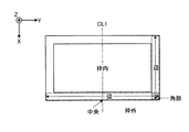
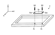
ここで、以下の説明を分かりやすくする観点から、本実施形態における枠体2の各部位の名称について、図4Aおよび図4Bを用いて述べておく。図4Aは、枠体2の各部位を説明するための模式的な斜視図であり、図4Bは、枠体2の各部位を説明するための模式的な平面図である。なお、図4Aでは、枠体2を構成する2枚の枠部材のうち、1枚分のみを示している。
Here, from the viewpoint of making the following description easy to understand, the names of the respective parts of the
図4Aに示すように、本実施形態では、枠体2が有する端面のうち、XY平面に平行な端面を「主面」と表現する。また、同じく枠体2が有する端面のうち、XZ平面あるいはYZ平面に平行な端面を「側面」と表現する。
As illustrated in FIG. 4A, in the present embodiment, among the end surfaces of the
また、図4Bに示すように、本実施形態では、長手方向あるいは短手方向の骨を「辺」と表現する。また、かかる「辺」と「辺」が重なる部分を「角部」と表現する(図中の斜線で塗りつぶした斜線領域参照)。 Further, as shown in FIG. 4B, in the present embodiment, a bone in the longitudinal direction or the lateral direction is expressed as “side”. In addition, a portion where the “side” and “side” overlap is expressed as a “corner” (see the hatched area filled with the hatched line in the drawing).
また、枠体2の中心線CL1と「辺」が交差する部分を「中央」と表現する。なお、図4Bには長手方向の中心線CL1と交差する「中央」のみ図示しているが、短手方向についてもかかる表現は同様にあてはまるものとする。
Further, a portion where the center line CL1 of the
また、図4Bは、枠体2が直線状の「辺」のみからなる略矩形状である場合の例示であるが、両端を有する骨であれば、「辺」は曲線状であってもよい。
4B is an example of the case where the
また、図4Bに示すように、本実施形態では、枠体2の内側の領域を「枠内」と、また外側の領域を「枠外」と、それぞれ表現する。
As shown in FIG. 4B, in the present embodiment, the inner area of the
図3Aおよび図3Bの説明に戻り、実施形態に係る音響発生器1について詳細に説明する。そして、本実施形態では、図3Aおよび図3Bに示すように、上述の端子2bを、枠体2の主面に、枠体2の中央を避けて設けることとした。また、これに関連して、端子板2aについては、枠体2の辺の中央から枠体2の角部寄りにずらして設けることとした。
Returning to the description of FIG. 3A and FIG. 3B, the
かかる構成により得られる効果について、まず端子2bから説明する。振動体3aの共振に誘導されて枠体2自体も振動する点については既に述べたが、かかる枠体2に端子2bが設けられることによって、端子2bの周囲で枠体2を伝播する振動波を乱すことができる。
The effect obtained by this configuration will be described first from the terminal 2b. Although the point that the
とりわけ、端子2bへ電気信号が入力された場合、端子2bの周囲は部分的に温度上昇するため、熱膨張を起こして振動波は乱れやすい。これにより、枠体2から振動体3aへ返る反射波を乱すことができる。
In particular, when an electrical signal is input to the terminal 2b, the temperature around the terminal 2b partially rises, so that thermal expansion easily occurs and vibration waves are likely to be disturbed. Thereby, the reflected wave returning from the
そして、その結果、共振周波数を部分的に揃わなくさせることができるので、共振点の音圧のピークPをばらつかせ、音圧の周波数特性を平坦化させることができる。すなわち、良好な音圧の周波数特性を得ることができる。 As a result, the resonance frequencies can be partially unbalanced, so that the sound pressure peak P at the resonance point can be varied and the frequency characteristics of the sound pressure can be flattened. That is, it is possible to obtain a favorable frequency characteristic of sound pressure.
また、端子2bは、音響発生器1の発生させる音声が伝播する側である枠体2の主面側に設けられることで、音声信号に誘導された振動波が端子2bを振動させやすくなる。
Further, the
したがって、端子2bの周囲では、伝播される振動波が乱されやすくなり、これにともなって共振周波数を部分的に揃わなくさせることができる。すなわち、共振点の音圧のピークPをばらつかせ、良好な音圧の周波数特性を得ることができる。
Therefore, the propagating vibration wave is likely to be disturbed around the
また、端子2bは、枠体2の中央を避けて設けられることで、上述の複合振動体全体の形状に非対称性をもたせることができるので、枠体2から振動体3aへの反射波を乱し、反射波の対称性を低下させることができる。
Further, since the terminal 2b is provided so as to avoid the center of the
これにより、やはり共振周波数を部分的に揃わなくさせることができるので、共振点の音圧のピークPをばらつかせ、良好な音圧の周波数特性を得ることができる。 As a result, the resonance frequencies can also be partially unbalanced, so that the sound pressure peak P at the resonance point can be varied and a good frequency characteristic of the sound pressure can be obtained.
つづいて、端子板2aによる効果について説明する。端子板2aは、まず枠体2に設けられることで、枠体2の表面を伝播する振動波をかかる端子板2aの存在する部位で反射させることができる。
Next, effects of the
すなわち、共振周波数を部分的に揃わなくさせることができるので、共振点の音圧のピークPをばらつかせ、良好な音圧の周波数特性を得ることができる。 That is, since the resonance frequencies can be partially unbalanced, the sound pressure peak P at the resonance point can be varied to obtain a favorable sound pressure frequency characteristic.
とりわけ、端子板2aに、上述のようにガラスエポキシ基板を用いた場合、ヤング率の異なる素材が分散した構造であることから、端子板2aの周囲の振動波を激しく乱すことができる。したがって、共振周波数を部分的に揃わなくさせるうえで、より効果的である。
In particular, when the glass epoxy substrate is used for the
また、端子板2aは、枠体2の辺の中央から枠体2の角部寄りにずらして設けられることで、上述の複合振動体全体の形状に非対称性をもたせることができる。これにより、枠体2から振動体3aへの反射波を乱し、反射波の対称性を低下させることができるので、共振周波数を部分的に揃わなくさせることができる。すなわち、やはり共振点の音圧のピークPをばらつかせ、良好な音圧の周波数特性を得ることができる。
Further, the
なお、図3Bに示すように、端子板2aは、枠体2の角部と枠体2の辺の中央との間に設けられることが好ましい。この場合、2つの辺が交差することで剛性の高い(すなわち、振動しにくい)角部を避けつつ、複合振動体全体の形状に非対称性をもたせることができるので、より効果的に枠体2から振動体3aへの反射波を乱すことができる。
As shown in FIG. 3B, the
また、これを踏まえつつ、端子板2aは、枠体2の長手方向の辺に設けられることが好ましい。これにより、短手方向の辺に設けられる場合よりも反射波の対称性を低下させることができるので、より効果的に共振周波数を部分的に揃わなくさせることができる。
Moreover, it is preferable to provide the
そして、このような端子板2a上に端子2bを設けることによって、端子板2aおよび端子2bによる効果を相乗的に得ることができる。すなわち、より効果的に共振点の音圧のピークPをばらつかせ、良好な音圧の周波数特性を得ることができる。
And by providing the terminal 2b on such a
また、図3Aに示すように複数個(ここでは、2個)の端子2bが設けられる場合、端子2bそれぞれが異なる共振ピークをもつことができるので、端子2bの周囲の振動波をさらに乱すことができる。したがって、これによっても共振周波数を部分的に揃わなくさせることができる。
In addition, when a plurality of (in this case, two)
また、同じく複数個の端子2bが設けられる場合、少なくとも1つの端子2bの極性がその他の端子2bの極性と異なることがより効果的である。すなわち、端子2bの極性が異なれば、端子2bそれぞれに異なった信号成分があるので、端子2bそれぞれの周囲の温度上昇が異なることとなる。したがって、端子板2aを伝播する振動波をさらに乱すことができるので、共振周波数を部分的に揃わなくさせることができる。
Similarly, when a plurality of
また、端子2bは、リード線6a、6bによって、圧電素子5と接続されるので、リード線6a、6bを介して圧電素子5の周囲の振動を拾うことができる。これにより、さらに端子2bの周囲で振動波を効果的に乱すことができる。
Further, since the terminal 2b is connected to the
なお、図3Cに示すように、リード線6a、6bは(6aは図示略)、弛みをもたせて端子2bおよび圧電素子5の間に接続されることが好ましい。これにより、端子2bから圧電素子5への振動を減衰することができるのでノイズの発生を抑え、クリアな音質の高い音響を発生させることができる。また、端子2bおよび圧電素子5への応力を抑えられるので、耐久性を向上させ、製品寿命を延ばすことができる。
As shown in FIG. 3C, the
また、ノイズの発生を抑える点については、端子2bは、枠体2の素材よりも軟らかい素材からなることが好ましい。これにより、枠体2で生じる振動を減衰することができるので、やはりノイズの発生を抑えることができる。
In terms of suppressing the generation of noise, the
また、図3Aおよび図3Bに示すように、端子2bは、枠体2の枠外または枠内にはみ出さないように設けられることで、端子2b自体の振動の自由度を規制される。これにより、端子2bからの音鳴りを抑えることができ、やはりノイズの発生を抑えることができる。
As shown in FIGS. 3A and 3B, the
なお、逆に、端子2bは、枠体2の枠外または枠内にはみ出すように設けられてもよい。かかる点については、図5Bを用いて後述する。また、図3Cの、二点鎖線で囲まれたM1部は、図5Fを用いた説明において拡大図としてあらためて示す。
On the contrary, the terminal 2b may be provided so as to protrude outside the
次に、図5A〜図5Jを用いて、端子板2aまたは端子2bの変形例について順次説明する。図5A〜図5D、および、図5H〜図5Jは順に、端子板2aまたは端子2bの変形例を示す模式的な平面図(その1)〜(その7)である。また、図5Eは、端子板2aの変形例の一つを示す模式的な斜視図である。また、図5Fは、端子2bの変形例の一つを示す模式的な断面図、図5Gは、図3Bの変形例を示すB−B’線断面図である。
Next, modified examples of the
まず、図5Aに示すように、端子板2aは、枠体2の枠外または枠内にはみ出すように設けられてもよい。かかる場合、振動体3aの振動に誘発されて枠体2が振動しても、端子板2aのはみ出した部分は共振周波数がずれるため、端子2bの周囲を伝播する枠体2の振動波をさらに乱すことができる。その結果、枠体2から振動体3aへの反射波もさらに乱すことができる。
First, as illustrated in FIG. 5A, the
すなわち、共振周波数を部分的に揃わなくさせ、共振点の音圧のピークPをばらつかせて、良好な音圧の周波数特性を得ることができる。 That is, it is possible to obtain a favorable frequency characteristic of sound pressure by making the resonance frequencies partially ununiform and by varying the sound pressure peak P at the resonance point.
また、図5Aでは、端子2bが、枠体2の主面内に位置するように端子板2a上に設けられる場合の例を示したが、図5Bに示すように、端子2bを枠体2の枠外または枠内にはみ出すような位置に設けてもよい。この場合もやはり図5Aの場合と同様の理由により、共振周波数を部分的に揃わなくさせ、共振点の音圧のピークPをばらつかせて、良好な音圧の周波数特性を得ることができる。
5A shows an example in which the
また、図5Cに示すように、端子板2aは、枠体2の辺と平面視で非平行となるように設けられてもよい。具体的には、枠体2の辺の中心線CL2と、端子板2aの中心線CL3とが、平面視で非平行となるような場合である。
Further, as shown in FIG. 5C, the
かかる場合、振動体3aの振動に誘発されて枠体2が振動しても、端子板2aが枠体2と非平行であることから端子板2aの領域でさらに共振周波数がずれることとなる。したがって、端子2bの周囲を伝播する枠体2の振動波をさらに乱すことができるので、枠体2から振動体3aへの反射波もまたさらに乱すことができる。
In this case, even if the
すなわち、共振周波数を部分的に揃わなくさせ、共振点の音圧のピークPをばらつかせて、良好な音圧の周波数特性を得ることができる。 That is, it is possible to obtain a favorable frequency characteristic of sound pressure by making the resonance frequencies partially ununiform and by varying the sound pressure peak P at the resonance point.
また、このように非平行であることで、複合振動体としての形状に非対称性をもたせることができる。すなわち、反射波の対称性を低下させ、共振周波数を部分的に揃わなくさせることができる。 Further, by being non-parallel in this way, it is possible to give asymmetry to the shape of the composite vibrator. That is, the symmetry of the reflected wave can be reduced, and the resonance frequencies can be partially not aligned.
これに関連して、図5Dに示すように、端子2bが、枠体2の辺と平面視で非平行となるように設けられてもよい。具体的には、2つの端子2bを結ぶ線CL4と、枠体2の辺の中心線CL2とが、平面視で非平行となるような場合である。
In this connection, as shown in FIG. 5D, the terminal 2b may be provided so as to be non-parallel to the side of the
この場合もまた図5Cの場合と同様の理由により、共振周波数を部分的に揃わなくさせ、共振点の音圧のピークPをばらつかせて、良好な音圧の周波数特性を得ることができる。 Also in this case, for the same reason as in the case of FIG. 5C, the resonance frequency is partially unbalanced, and the sound pressure peak P at the resonance point is varied to obtain a favorable sound pressure frequency characteristic. .
また、図5Eに示すように、端子板2aには、孔部2aaを設けてもよい。たとえば、図5Eは、ネジSCのネジ孔として孔部2aaを端子板2aに設け、枠体2にやはり設けたネジ孔2cへネジ締結することで、端子板2aを枠体2へ取り付ける場合を示している。ここで、たとえば、ネジSCは、端子2bを兼ねてもよい。
Moreover, as shown to FIG. 5E, you may provide the hole 2aa in the
また、図5Eに示す例に関連して、図5Fに示すように、端子2bに対して孔部2baを設けることとしてもよい。このように、端子板2aまたは端子2bに対して、孔部2aaや孔部2baのような孔を設けた場合、振動に応じて孔の内部で振動波を形成することができるので、枠体2から振動体3aへの反射波をさらに乱すことができる。
Further, in relation to the example shown in FIG. 5E, as shown in FIG. 5F, a hole 2ba may be provided for the terminal 2b. As described above, when a hole such as the hole 2aa or the hole 2ba is provided in the
このとき、孔と他部材(たとえば、枠体2)との間に継ぎ目があれば、かかる継ぎ目で振動波およびその反射波をさらに乱すことができる。また、音圧が高い場合には孔の周囲を変形させることができるので、波を乱し、共振周波数を部分的に揃わなくさせるうえではより効果的である。 At this time, if there is a joint between the hole and the other member (for example, the frame 2), the vibration wave and its reflected wave can be further disturbed by the joint. In addition, when the sound pressure is high, the periphery of the hole can be deformed, which is more effective in disturbing the wave and making the resonance frequency partially uneven.
また、図5Fに示すように、端子2bは、中間層2d(接着剤のような接合材)を用いて端子板2aへ接合されることが好ましい。かかる場合、端子2bと中間層2dとがそれぞれ枠体2の振動波を乱れさせるので、相乗的に激しく端子2bの周囲の振動波を乱れさせることができる。すなわち、この場合も、共振周波数を部分的に揃わなくさせるうえでより効果的である。
Further, as shown in FIG. 5F, the
なお、端子板2aが絶縁性を有する場合、中間層2dは、必ずしも絶縁性を有することを要しない。すなわち、導電性を有する中間層2dを用いても構わない。また、中間層2dが絶縁性を有する場合、端子板2aは、必ずしも絶縁性を有することを要しない。たとえば、金属製の端子板2aを用いても構わない。つまり、中間層2dおよび端子板2aのうち、少なくとも一方が絶縁性を有していればよい。したがって、中間層2dとしては、接着剤だけでなく、座金などの部材であってもよい。また、図5Gに示すように、端子2bだけでなく、端子板2aが中間層2dを用いて枠体2へ接合されてもよい。
In addition, when the
ところで、図3Bを用いた説明では、端子板2aは、枠体2の角部と枠体2の辺の中央との間に設けられることが好ましいこととしたが、かかる場合に限定されるものではない。
By the way, in the description using FIG. 3B, the
たとえば、図5Hに示すように、端子板2aは、中心線CL1に係る枠体2の中央に重なっていてもよい。具体的には、枠体2の中央に重なっていても、端子板2aの中心線CL5が、角部C1寄りあるいは角部C2寄りに、枠体2の中央からずれていればよい。
For example, as illustrated in FIG. 5H, the
このような場合でも、少なくとも複合振動体全体の形状に非対称性をもたせることができるので、枠体2から振動体3aへの反射波の対称性を低下させ、乱すことができる。なお、ここで図5Hに示すように、少なくとも端子2bもまた枠体2の中央から避けて設けられていれば、より効果的である。
Even in such a case, since at least the shape of the entire composite vibrator can be asymmetric, the symmetry of the reflected wave from the
また、図5Iに示すように、端子板2aは、枠体2の角部(ここでは、角部C1)に重なるように設けられてもよい。この場合も、図5Hの場合と同様に、少なくとも複合振動体全体の形状に非対称性をもたせることができるので、枠体2から振動体3aへの反射波の対称性を低下させ、乱すことができる。
Further, as shown in FIG. 5I, the
また、図5Jに示すように、端子2bだけではなく、端子板2aもまた複数個設けられてもよい。この場合、端子板2aの2個目以降は、電気信号の導通を行わないダミーとして設けられてよい。
Further, as shown in FIG. 5J, not only the terminal 2b but also a plurality of
このダミーとして設けられる場合であっても、枠体2に端子板2aおよび端子2bが複数個存在するだけで、枠体2から振動体3aへの反射波を乱すことは可能である。
Even when the dummy is provided, the reflected wave from the
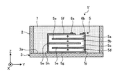
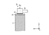
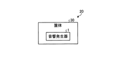
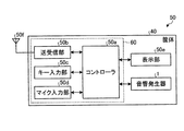
次に、これまで説明してきた実施形態に係る音響発生器1を搭載した音響発生装置および電子機器について、図6Aおよび図6Bを用いて説明する。図6Aは、実施形態に係る音響発生装置20の構成を示す図であり、図6Bは、実施形態に係る電子機器50の構成を示す図である。なお、両図には、説明に必要となる構成要素のみを示しており、一般的な構成要素についての記載を省略している。
Next, a sound generation device and an electronic apparatus equipped with the
音響発生装置20は、いわゆるスピーカのような発音装置であり、図6Aに示すように、たとえば、音響発生器1と、音響発生器1を収容する筐体30を備える。筐体30は、音響発生器1の発する音響を内部で共鳴させるとともに、筐体30に形成された図示せぬ開口から音響を外部へ放射する。このような筐体30を有することにより、たとえば低周波数帯域における音圧を高めることができる。
The
また、音響発生器1は、種々の電子機器50に搭載することができる。たとえば、次に示す図6Bでは、電子機器50が、携帯電話やタブレット端末のような携帯端末装置であるものとする。
The
図6Bに示すように、電子機器50は、電子回路60を備える。電子回路60は、たとえば、コントローラ50aと、送受信部50bと、キー入力部50cと、マイク入力部50dとから構成される。電子回路60は、音響発生器1に接続されており、音響発生器1へ音声信号を出力する機能を有している。音響発生器1は電子回路60から入力された音声信号に基づいて音響を発生させる。
As shown in FIG. 6B, the
また、電子機器50は、表示部50eと、アンテナ50fと、音響発生器1とを備える。また、電子機器50は、これら各デバイスを収容する筐体40を備える。
The
なお、図6Bでは、1つの筐体40にコントローラ50aをはじめとする各デバイスがすべて収容されている状態をあらわしているが、各デバイスの収容形態を限定するものではない。本実施形態では、少なくとも電子回路60と音響発生器1とが、1つの筐体40に収容されていればよい。
6B shows a state in which each device including the controller 50a is accommodated in one
コントローラ50aは、電子機器50の制御部である。送受信部50bは、コントローラ50aの制御に基づき、アンテナ50fを介してデータの送受信などを行う。
The controller 50 a is a control unit of the
キー入力部50cは、電子機器50の入力デバイスであり、操作者によるキー入力操作を受け付ける。マイク入力部50dは、同じく電子機器50の入力デバイスであり、操作者による音声入力操作などを受け付ける。
The
表示部50eは、電子機器50の表示出力デバイスであり、コントローラ50aの制御に基づき、表示情報の出力を行う。
The
そして、音響発生器1は、電子機器50における音響出力デバイスとして動作する。なお、音響発生器1は、電子回路60のコントローラ50aに接続されており、コントローラ50aによって制御された電圧の印加を受けて音響を発することとなる。
The
ところで、図6Bでは、電子機器50が携帯用端末装置であるものとして説明を行ったが、電子機器50の種別を問うものではなく、音響を発する機能を有する様々な民生機器に適用されてよい。たとえば、薄型テレビやカーオーディオ機器は無論のこと、「話す」といった音響を発する機能を有する製品、例を挙げれば、掃除機や洗濯機、冷蔵庫、電子レンジなどといった種々の製品に用いられてよい。
In FIG. 6B, the
上述してきたように、実施形態に係る音響発生器は、励振器(圧電素子)と、振動体と、枠体と、導線(リード線)とを備える。上記励振器は、電気信号が入力されて振動する。上記振動体は、上記励振器が取り付けられており、かかる励振器の振動によってこの励振器とともに振動する。上記枠体は、上記振動体の外周部に設けられ、かかる振動体を略扁平に支持する。上記導線は、上記励振器に接続され、かかる励振器へ電気信号を入力する。また、上記枠体は、上記導線への接続点となる端子を有している。 As described above, the sound generator according to the embodiment includes an exciter (piezoelectric element), a vibrating body, a frame body, and a conducting wire (lead wire). The exciter vibrates when an electric signal is input thereto. The vibrator is provided with the exciter, and vibrates with the exciter by the vibration of the exciter. The frame body is provided on an outer peripheral portion of the vibrating body and supports the vibrating body substantially flat. The conductor is connected to the exciter and inputs an electrical signal to the exciter. Moreover, the said frame has a terminal used as the connection point to the said conducting wire.
したがって、実施形態に係る音響発生器によれば、良好な音圧の周波数特性を得ることができる。 Therefore, according to the sound generator according to the embodiment, it is possible to obtain a favorable frequency characteristic of sound pressure.
なお、上述した実施形態では、枠体の枠内において圧電素子および振動体を覆ってしまうように樹脂層を形成する場合を例に挙げたが、かかる樹脂層を必ずしも形成しなくともよい。 In the embodiment described above, the case where the resin layer is formed so as to cover the piezoelectric element and the vibrating body in the frame of the frame body is described as an example. However, such a resin layer may not necessarily be formed.
また、上述した実施形態では、樹脂フィルムなどの薄膜で振動板を構成する場合を例に挙げたが、これに限られるものではなく、たとえば、板状の部材で構成することとしてもよい。 Further, in the above-described embodiment, the case where the diaphragm is configured by a thin film such as a resin film has been described as an example. However, the present invention is not limited thereto, and may be configured by a plate-like member, for example.
また、上述した実施形態では、励振器が圧電素子である場合を例に挙げて説明したが、励振器としては、圧電素子に限定されるものではなく、電気信号が入力されて振動する機能を有しているものであればよい。 In the above-described embodiment, the case where the exciter is a piezoelectric element has been described as an example. However, the exciter is not limited to the piezoelectric element, and has a function of vibrating when an electric signal is input. What is necessary is just to have.
たとえば、スピーカを振動させる励振器としてよく知られた、動電型の励振器や、静電型の励振器や、電磁型の励振器であっても構わない。 For example, an electrodynamic exciter, an electrostatic exciter, or an electromagnetic exciter well known as an exciter for vibrating a speaker may be used.
なお、動電型の励振器は、永久磁石の磁極の間に配置されたコイルに電流を流してコイルを振動させるようなものであり、静電型の励振器は、向き合わせた2つの金属板にバイアスと電気信号とを流して金属板を振動させるようなものであり、電磁型の励振器は、電気信号をコイルに流して薄い鉄板を振動させるようなものである。 The electrodynamic exciter is such that an electric current is passed through a coil disposed between the magnetic poles of a permanent magnet to vibrate the coil. A bias and an electric signal are passed through the plate to vibrate the metal plate, and an electromagnetic exciter is an electric signal that is passed through the coil to vibrate a thin iron plate.
さらなる効果や変形例は、当業者によって容易に導き出すことができる。このため、本発明のより広範な態様は、以上のように表しかつ記述した特定の詳細および代表的な実施形態に限定されるものではない。したがって、添付の特許請求の範囲およびその均等物によって定義される総括的な発明の概念の精神または範囲から逸脱することなく、様々な変更が可能である。 Further effects and modifications can be easily derived by those skilled in the art. Thus, the broader aspects of the present invention are not limited to the specific details and representative embodiments shown and described above. Accordingly, various modifications can be made without departing from the spirit or scope of the general inventive concept as defined by the appended claims and their equivalents.
1、1’ 音響発生器
2 枠体
2a 端子板
2aa 孔部
2b 端子
2ba 孔部
2c ネジ孔
2d 中間層
3 振動板
3a 振動体
5 圧電素子
5a、5b、5c、5d 圧電体層
5e 内部電極層
5f、5g 表面電極層
5h、5j 外部電極
6a、6b リード線
7 樹脂層
20 音響発生装置
30、40 筐体
50 電子機器
50a コントローラ
50b 送受信部
50c キー入力部
50d マイク入力部
50e 表示部
50f アンテナ
60 電子回路
C1、C2 角部
P ピーク
SC ネジDESCRIPTION OF
Claims (10)
前記励振器が取り付けられており、該励振器の振動によって該励振器とともに振動する振動体と、
前記振動体の外周部に設けられ、該振動体を扁平に支持する枠体と、
前記励振器に接続され、該励振器へ電気信号を入力する導線とを備え、
前記枠体は前記導線への接続点となる複数個の端子を有しており、該複数個の端子は、当該複数個の端子の少なくとも2つを結ぶ線が平面視で前記枠体の辺と非平行となるように設けられていることを特徴とする音響発生器。 An exciter that vibrates upon receipt of an electrical signal;
A vibrator that is mounted with the exciter and vibrates with the exciter by vibration of the exciter;
Provided on an outer peripheral portion of the vibrating body, a frame body for supporting the vibrating body Bian earnestly,
A conductor connected to the exciter and for inputting an electrical signal to the exciter;
The frame has a plurality of terminals to which the connection point of the previous SL conductors, several terminals plurality is a line connecting at least two of said plurality of terminals of said frame in a plan view A sound generator characterized by being provided so as to be non-parallel to the side .
前記励振器が取り付けられており、該励振器の振動によって該励振器とともに振動する振動体と、
前記振動体の外周部に設けられ、該振動体を扁平に支持する枠体と、
前記励振器に接続され、該励振器へ電気信号を入力する導線と、
前記枠体に設けられた基板とを備え、
前記導線への接続点となる端子が前記基板上に設けられているとともに、前記基板が前記枠体の辺の中央から前記枠体の角部寄りにずらして設けられていることを特徴とする音響発生器。 An exciter that vibrates upon receipt of an electrical signal;
A vibrator that is mounted with the exciter and vibrates with the exciter by vibration of the exciter;
A frame body provided on an outer peripheral portion of the vibrating body and supporting the vibrating body flat;
A conductor connected to the exciter and for inputting an electrical signal to the exciter;
And a substrate provided on the frame body,
With terminals to which the connection point to the conductors is provided on the substrate, to characterized in that the substrate is provided by shifting the corner portion toward the frame from the center of the sides of the frame Ruoto sound generator.
前記励振器が取り付けられており、該励振器の振動によって該励振器とともに振動する振動体と、
前記振動体の外周部に設けられ、該振動体を扁平に支持する枠体と、
前記励振器に接続され、該励振器へ電気信号を入力する導線と、
前記枠体に設けられた基板とを備え、
前記導線への接続点となる端子が前記基板上に設けられているとともに、前記基板が前記枠体の辺と平面視で非平行となるように設けられていることを特徴とする音響発生器。 An exciter that vibrates upon receipt of an electrical signal;
A vibrator that is mounted with the exciter and vibrates with the exciter by vibration of the exciter;
A frame body provided on an outer peripheral portion of the vibrating body and supporting the vibrating body flat;
A conductor connected to the exciter and for inputting an electrical signal to the exciter;
A substrate provided on the frame,
With terminals to which the connection point to the conductors is provided on the substrate, wherein the to Ruoto sound that the substrate is disposed so as to be non-parallel with the sides in a plan view of the frame Generator.
前記励振器が取り付けられており、該励振器の振動によって該励振器とともに振動する振動体と、
前記振動体の外周部に設けられ、該振動体を扁平に支持する枠体と、
前記励振器に接続され、該励振器へ電気信号を入力する導線と、
前記枠体に設けられた基板とを備え、
前記導線への接続点となる端子が前記基板上に設けられているとともに、前記基板が前記枠体の枠外または枠内へはみ出すように設けられていることを特徴とする音響発生器。 An exciter that vibrates upon receipt of an electrical signal;
A vibrator that is mounted with the exciter and vibrates with the exciter by vibration of the exciter;
A frame body provided on an outer peripheral portion of the vibrating body and supporting the vibrating body flat;
A conductor connected to the exciter and for inputting an electrical signal to the exciter;
A substrate provided on the frame,
With terminals to which the connection point to the conductors is provided on the substrate, wherein the to Ruoto sound generator that the substrate is provided so as to protrude into the frame of the outside-frame or the frame.
前記励振器が取り付けられており、該励振器の振動によって該励振器とともに振動する振動体と、
前記振動体の外周部に設けられ、該振動体を扁平に支持する枠体と、
前記励振器に接続され、該励振器へ電気信号を入力する導線とを備え、
前記枠体は前記導線への接続点となる端子を有しており、該端子は気孔を有する中間層を介して設けられていることを特徴とする音響発生器。 An exciter that vibrates upon receipt of an electrical signal;
A vibrator that is mounted with the exciter and vibrates with the exciter by vibration of the exciter;
A frame body provided on an outer peripheral portion of the vibrating body and supporting the vibrating body flat;
A conductor connected to the exciter and for inputting an electrical signal to the exciter;
The frame has a terminal which is a connection point to the leads, wherein the to Ruoto sound generator that said pin is provided through an intermediate layer having pores.
該音響発生器を収容する筐体とを備えることを特徴とする音響発生装置。 The sound generator according to any one of claims 1 to 8 ,
A sound generator comprising: a housing for housing the sound generator.
該音響発生器に接続された電子回路と、
該電子回路および前記音響発生器を収容する筐体とを備え、
前記音響発生器から音響を発生させる機能を有することを特徴とする電子機器。 The sound generator according to any one of claims 1 to 8 ,
An electronic circuit connected to the acoustic generator;
A housing for housing the electronic circuit and the acoustic generator;
An electronic apparatus having a function of generating sound from the sound generator.
Applications Claiming Priority (5)
| Application Number | Priority Date | Filing Date | Title |
|---|---|---|---|
| JP2012275132 | 2012-12-17 | ||
| JP2012275132 | 2012-12-17 | ||
| JP2012280204 | 2012-12-21 | ||
| JP2012280204 | 2012-12-21 | ||
| PCT/JP2013/067921 WO2014097668A1 (en) | 2012-12-17 | 2013-06-28 | Acoustic generator, acoustic genera tion device, and electronic device |
Publications (2)
| Publication Number | Publication Date |
|---|---|
| JP5908994B2 true JP5908994B2 (en) | 2016-04-26 |
| JPWO2014097668A1 JPWO2014097668A1 (en) | 2017-01-12 |
Family
ID=50978022
Family Applications (1)
| Application Number | Title | Priority Date | Filing Date |
|---|---|---|---|
| JP2014552953A Expired - Fee Related JP5908994B2 (en) | 2012-12-17 | 2013-06-28 | SOUND GENERATOR, SOUND GENERATOR, AND ELECTRONIC DEVICE |
Country Status (7)
| Country | Link |
|---|---|
| US (1) | US9380365B2 (en) |
| EP (1) | EP2947897B1 (en) |
| JP (1) | JP5908994B2 (en) |
| KR (1) | KR101507747B1 (en) |
| CN (1) | CN103999482B (en) |
| TW (1) | TWI545967B (en) |
| WO (1) | WO2014097668A1 (en) |
Families Citing this family (8)
| Publication number | Priority date | Publication date | Assignee | Title |
|---|---|---|---|---|
| CN105637898B (en) * | 2014-09-26 | 2019-04-26 | 京瓷株式会社 | Sound generator, sound generating device, and electronic equipment |
| CN105812989A (en) * | 2014-12-31 | 2016-07-27 | 鸿富锦精密工业(深圳)有限公司 | Loudspeaker |
| JP6434373B2 (en) * | 2015-06-11 | 2018-12-05 | 京セラ株式会社 | Piezoelectric actuator, piezoelectric vibration device including the same, sound generator, sound generator, electronic device |
| JP6411958B2 (en) * | 2015-06-29 | 2018-10-24 | 京セラ株式会社 | SOUND GENERATOR, SOUND GENERATOR HAVING THE SAME, AND ELECTRONIC DEVICE |
| JP7006017B2 (en) * | 2017-03-10 | 2022-01-24 | Tdk株式会社 | Vibration device |
| JP7087942B2 (en) * | 2018-11-16 | 2022-06-21 | Tdk株式会社 | Vibration devices, electronic devices, and how to drive vibration devices |
| JP7754110B2 (en) * | 2021-01-25 | 2025-10-15 | Agc株式会社 | soundproofing device |
| KR20230099099A (en) * | 2021-12-27 | 2023-07-04 | 엘지디스플레이 주식회사 | Apparatus |
Citations (3)
| Publication number | Priority date | Publication date | Assignee | Title |
|---|---|---|---|---|
| JPS62109600U (en) * | 1985-12-26 | 1987-07-13 | ||
| JP2001275190A (en) * | 2000-03-28 | 2001-10-05 | Matsushita Electric Ind Co Ltd | Piezo speaker |
| JP2012110018A (en) * | 2010-06-25 | 2012-06-07 | Kyocera Corp | Acoustic generator |
Family Cites Families (15)
| Publication number | Priority date | Publication date | Assignee | Title |
|---|---|---|---|---|
| US1919632A (en) * | 1930-04-04 | 1933-07-25 | Rca Corp | Sound radiator |
| GB1219918A (en) * | 1968-08-08 | 1971-01-20 | Standard Telephones Cables Ltd | Improvements in and relating to moving coil transducers |
| US3697790A (en) * | 1970-12-02 | 1972-10-10 | William T Flint | Transducers having piezoelectric struts |
| JPS5379525A (en) * | 1976-12-23 | 1978-07-14 | Sony Corp | Compound diaphtagm for speakers |
| JPS59129290U (en) * | 1983-02-18 | 1984-08-30 | 三洋電機株式会社 | speaker |
| JPH0732837B2 (en) * | 1985-11-07 | 1995-04-12 | 松下電器産業株式会社 | Automatic washing machine |
| JP3160070B2 (en) * | 1992-04-30 | 2001-04-23 | 呉羽化学工業株式会社 | Vibration-electric energy conversion element |
| CN1038179C (en) * | 1992-09-30 | 1998-04-22 | 星精密株式会社 | Electro-acoustic converter |
| JP2004023436A (en) * | 2002-06-17 | 2004-01-22 | Nihon Ceratec Co Ltd | Piezoelectric loudspeaker |
| JP2004266424A (en) * | 2003-02-28 | 2004-09-24 | Citizen Electronics Co Ltd | Microspeaker |
| JP2005311415A (en) * | 2004-04-16 | 2005-11-04 | Nec Tokin Corp | Acoustic vibration generation element |
| CN101119597B (en) * | 2006-08-02 | 2011-06-08 | 金大仁 | Panel type loudspeaker structure |
| KR101159734B1 (en) * | 2008-12-22 | 2012-06-28 | 한국전자통신연구원 | Piezoelectric speaker and method for forming the same |
| KR101166727B1 (en) * | 2010-06-17 | 2012-07-19 | 주식회사 이엠텍 | A sound converting apparatus |
| JP6016945B2 (en) * | 2012-12-12 | 2016-10-26 | 京セラ株式会社 | SOUND GENERATOR, SOUND GENERATOR, AND ELECTRONIC DEVICE |
-
2013
- 2013-06-28 US US14/647,965 patent/US9380365B2/en not_active Expired - Fee Related
- 2013-06-28 EP EP13864576.7A patent/EP2947897B1/en not_active Not-in-force
- 2013-06-28 KR KR1020137026844A patent/KR101507747B1/en not_active Expired - Fee Related
- 2013-06-28 CN CN201380003242.XA patent/CN103999482B/en not_active Expired - Fee Related
- 2013-06-28 WO PCT/JP2013/067921 patent/WO2014097668A1/en not_active Ceased
- 2013-06-28 JP JP2014552953A patent/JP5908994B2/en not_active Expired - Fee Related
- 2013-11-28 TW TW102143376A patent/TWI545967B/en not_active IP Right Cessation
Patent Citations (3)
| Publication number | Priority date | Publication date | Assignee | Title |
|---|---|---|---|---|
| JPS62109600U (en) * | 1985-12-26 | 1987-07-13 | ||
| JP2001275190A (en) * | 2000-03-28 | 2001-10-05 | Matsushita Electric Ind Co Ltd | Piezo speaker |
| JP2012110018A (en) * | 2010-06-25 | 2012-06-07 | Kyocera Corp | Acoustic generator |
Also Published As
| Publication number | Publication date |
|---|---|
| CN103999482A (en) | 2014-08-20 |
| US9380365B2 (en) | 2016-06-28 |
| TWI545967B (en) | 2016-08-11 |
| EP2947897A4 (en) | 2016-11-09 |
| EP2947897B1 (en) | 2019-05-01 |
| TW201427438A (en) | 2014-07-01 |
| US20150312661A1 (en) | 2015-10-29 |
| EP2947897A1 (en) | 2015-11-25 |
| JPWO2014097668A1 (en) | 2017-01-12 |
| CN103999482B (en) | 2017-02-22 |
| WO2014097668A1 (en) | 2014-06-26 |
| KR20140103031A (en) | 2014-08-25 |
| KR101507747B1 (en) | 2015-04-07 |
Similar Documents
| Publication | Publication Date | Title |
|---|---|---|
| JP5908994B2 (en) | SOUND GENERATOR, SOUND GENERATOR, AND ELECTRONIC DEVICE | |
| JP6016945B2 (en) | SOUND GENERATOR, SOUND GENERATOR, AND ELECTRONIC DEVICE | |
| JP5677639B2 (en) | SOUND GENERATOR, SOUND GENERATOR, AND ELECTRONIC DEVICE | |
| JP5627824B1 (en) | SOUND GENERATOR, SOUND GENERATOR, AND ELECTRONIC DEVICE | |
| JP6053794B2 (en) | SOUND GENERATOR, SOUND GENERATOR, AND ELECTRONIC DEVICE | |
| JP5602978B2 (en) | SOUND GENERATOR, SOUND GENERATOR, AND ELECTRONIC DEVICE | |
| WO2014097862A1 (en) | Acoustic generator, acoustic generation device, and electronic device | |
| JP2014127767A (en) | Acoustic generator, acoustic generating device, and electronic apparatus | |
| JP2014127843A (en) | Acoustic generator, acoustic generating device, and electronic apparatus | |
| JP5909169B2 (en) | SOUND GENERATOR, SOUND GENERATOR, AND ELECTRONIC DEVICE | |
| JP5934386B2 (en) | SOUND GENERATOR, SOUND GENERATOR, AND ELECTRONIC DEVICE | |
| JP6166038B2 (en) | SOUND GENERATOR, SOUND GENERATOR, AND ELECTRONIC DEVICE | |
| JP2014123812A (en) | Sound generator, sound generating system, and electronic apparatus | |
| JP6034182B2 (en) | SOUND GENERATOR, SOUND GENERATOR, AND ELECTRONIC DEVICE | |
| JP5952426B2 (en) | SOUND GENERATOR, SOUND GENERATOR, AND ELECTRONIC DEVICE | |
| JP6027827B2 (en) | SOUND GENERATOR, SOUND GENERATOR, AND ELECTRONIC DEVICE | |
| JP6092618B2 (en) | SOUND GENERATOR, SOUND GENERATOR, AND ELECTRONIC DEVICE | |
| WO2014104018A1 (en) | Sound generator, sound generating apparatus, and electronic apparatus | |
| WO2014091813A1 (en) | Acoustic generator, acoustic generation device, and electronic device | |
| JP2014116795A (en) | Sound generator, sound generation device and electronic apparatus |
Legal Events
| Date | Code | Title | Description |
|---|---|---|---|
| A521 | Request for written amendment filed |
Free format text: JAPANESE INTERMEDIATE CODE: A523 Effective date: 20160201 |
|
| TRDD | Decision of grant or rejection written | ||
| A01 | Written decision to grant a patent or to grant a registration (utility model) |
Free format text: JAPANESE INTERMEDIATE CODE: A01 Effective date: 20160301 |
|
| A61 | First payment of annual fees (during grant procedure) |
Free format text: JAPANESE INTERMEDIATE CODE: A61 Effective date: 20160324 |
|
| R150 | Certificate of patent or registration of utility model |
Ref document number: 5908994 Country of ref document: JP Free format text: JAPANESE INTERMEDIATE CODE: R150 |
|
| LAPS | Cancellation because of no payment of annual fees |