EP2947897B1 - Acoustic generator, acoustic generation device, and electronic device - Google Patents
Acoustic generator, acoustic generation device, and electronic device Download PDFInfo
- Publication number
- EP2947897B1 EP2947897B1 EP13864576.7A EP13864576A EP2947897B1 EP 2947897 B1 EP2947897 B1 EP 2947897B1 EP 13864576 A EP13864576 A EP 13864576A EP 2947897 B1 EP2947897 B1 EP 2947897B1
- Authority
- EP
- European Patent Office
- Prior art keywords
- frame
- terminals
- acoustic generator
- piezoelectric element
- rectangular frame
- Prior art date
- Legal status (The legal status is an assumption and is not a legal conclusion. Google has not performed a legal analysis and makes no representation as to the accuracy of the status listed.)
- Not-in-force
Links
- 239000011347 resin Substances 0.000 claims description 24
- 229920005989 resin Polymers 0.000 claims description 24
- 239000000758 substrate Substances 0.000 claims description 8
- 239000000463 material Substances 0.000 description 18
- 230000004048 modification Effects 0.000 description 16
- 238000012986 modification Methods 0.000 description 16
- 239000002131 composite material Substances 0.000 description 14
- 229910052751 metal Inorganic materials 0.000 description 8
- 239000002184 metal Substances 0.000 description 8
- 239000000853 adhesive Substances 0.000 description 7
- 230000001070 adhesive effect Effects 0.000 description 7
- 230000000694 effects Effects 0.000 description 7
- 239000010409 thin film Substances 0.000 description 7
- 230000009467 reduction Effects 0.000 description 6
- 238000010586 diagram Methods 0.000 description 5
- 239000010408 film Substances 0.000 description 5
- 239000011521 glass Substances 0.000 description 5
- 239000007769 metal material Substances 0.000 description 4
- 230000001629 suppression Effects 0.000 description 4
- 239000004593 Epoxy Substances 0.000 description 3
- 239000000919 ceramic Substances 0.000 description 3
- -1 polyethylene Polymers 0.000 description 3
- 239000011148 porous material Substances 0.000 description 3
- 230000005236 sound signal Effects 0.000 description 3
- KDLHZDBZIXYQEI-UHFFFAOYSA-N Palladium Chemical compound [Pd] KDLHZDBZIXYQEI-UHFFFAOYSA-N 0.000 description 2
- 230000002238 attenuated effect Effects 0.000 description 2
- 239000000470 constituent Substances 0.000 description 2
- 238000013016 damping Methods 0.000 description 2
- 238000009499 grossing Methods 0.000 description 2
- 230000006872 improvement Effects 0.000 description 2
- 230000006698 induction Effects 0.000 description 2
- 239000011810 insulating material Substances 0.000 description 2
- 229910052709 silver Inorganic materials 0.000 description 2
- 239000004332 silver Substances 0.000 description 2
- RYGMFSIKBFXOCR-UHFFFAOYSA-N Copper Chemical compound [Cu] RYGMFSIKBFXOCR-UHFFFAOYSA-N 0.000 description 1
- 239000004698 Polyethylene Substances 0.000 description 1
- 239000004642 Polyimide Substances 0.000 description 1
- 239000004743 Polypropylene Substances 0.000 description 1
- NIXOWILDQLNWCW-UHFFFAOYSA-N acrylic acid group Chemical group C(C=C)(=O)O NIXOWILDQLNWCW-UHFFFAOYSA-N 0.000 description 1
- 229910052782 aluminium Inorganic materials 0.000 description 1
- XAGFODPZIPBFFR-UHFFFAOYSA-N aluminium Chemical compound [Al] XAGFODPZIPBFFR-UHFFFAOYSA-N 0.000 description 1
- 230000006399 behavior Effects 0.000 description 1
- 238000006243 chemical reaction Methods 0.000 description 1
- 150000001875 compounds Chemical class 0.000 description 1
- 239000012141 concentrate Substances 0.000 description 1
- 230000008602 contraction Effects 0.000 description 1
- 229910052802 copper Inorganic materials 0.000 description 1
- 239000010949 copper Substances 0.000 description 1
- 230000007797 corrosion Effects 0.000 description 1
- 238000005260 corrosion Methods 0.000 description 1
- 230000002950 deficient Effects 0.000 description 1
- 230000007850 degeneration Effects 0.000 description 1
- 230000001419 dependent effect Effects 0.000 description 1
- 230000006866 deterioration Effects 0.000 description 1
- 230000005684 electric field Effects 0.000 description 1
- 239000011888 foil Substances 0.000 description 1
- 238000009413 insulation Methods 0.000 description 1
- 238000003475 lamination Methods 0.000 description 1
- HFGPZNIAWCZYJU-UHFFFAOYSA-N lead zirconate titanate Chemical compound [O-2].[O-2].[O-2].[O-2].[O-2].[Ti+4].[Zr+4].[Pb+2] HFGPZNIAWCZYJU-UHFFFAOYSA-N 0.000 description 1
- 229910052451 lead zirconate titanate Inorganic materials 0.000 description 1
- 229910052763 palladium Inorganic materials 0.000 description 1
- 229920000573 polyethylene Polymers 0.000 description 1
- 229920001721 polyimide Polymers 0.000 description 1
- 229920001155 polypropylene Polymers 0.000 description 1
- 230000004044 response Effects 0.000 description 1
- 229910001220 stainless steel Inorganic materials 0.000 description 1
- 239000010935 stainless steel Substances 0.000 description 1
- 229910052721 tungsten Inorganic materials 0.000 description 1
- 239000010937 tungsten Substances 0.000 description 1
- 238000005406 washing Methods 0.000 description 1
Images


Classifications
-
- H—ELECTRICITY
- H04—ELECTRIC COMMUNICATION TECHNIQUE
- H04R—LOUDSPEAKERS, MICROPHONES, GRAMOPHONE PICK-UPS OR LIKE ACOUSTIC ELECTROMECHANICAL TRANSDUCERS; DEAF-AID SETS; PUBLIC ADDRESS SYSTEMS
- H04R1/00—Details of transducers, loudspeakers or microphones
- H04R1/02—Casings; Cabinets ; Supports therefor; Mountings therein
-
- H—ELECTRICITY
- H04—ELECTRIC COMMUNICATION TECHNIQUE
- H04R—LOUDSPEAKERS, MICROPHONES, GRAMOPHONE PICK-UPS OR LIKE ACOUSTIC ELECTROMECHANICAL TRANSDUCERS; DEAF-AID SETS; PUBLIC ADDRESS SYSTEMS
- H04R17/00—Piezoelectric transducers; Electrostrictive transducers
-
- H—ELECTRICITY
- H04—ELECTRIC COMMUNICATION TECHNIQUE
- H04B—TRANSMISSION
- H04B1/00—Details of transmission systems, not covered by a single one of groups H04B3/00 - H04B13/00; Details of transmission systems not characterised by the medium used for transmission
- H04B1/38—Transceivers, i.e. devices in which transmitter and receiver form a structural unit and in which at least one part is used for functions of transmitting and receiving
-
- H—ELECTRICITY
- H04—ELECTRIC COMMUNICATION TECHNIQUE
- H04R—LOUDSPEAKERS, MICROPHONES, GRAMOPHONE PICK-UPS OR LIKE ACOUSTIC ELECTROMECHANICAL TRANSDUCERS; DEAF-AID SETS; PUBLIC ADDRESS SYSTEMS
- H04R3/00—Circuits for transducers, loudspeakers or microphones
-
- H—ELECTRICITY
- H04—ELECTRIC COMMUNICATION TECHNIQUE
- H04R—LOUDSPEAKERS, MICROPHONES, GRAMOPHONE PICK-UPS OR LIKE ACOUSTIC ELECTROMECHANICAL TRANSDUCERS; DEAF-AID SETS; PUBLIC ADDRESS SYSTEMS
- H04R1/00—Details of transducers, loudspeakers or microphones
- H04R1/06—Arranging circuit leads; Relieving strain on circuit leads
-
- H—ELECTRICITY
- H04—ELECTRIC COMMUNICATION TECHNIQUE
- H04R—LOUDSPEAKERS, MICROPHONES, GRAMOPHONE PICK-UPS OR LIKE ACOUSTIC ELECTROMECHANICAL TRANSDUCERS; DEAF-AID SETS; PUBLIC ADDRESS SYSTEMS
- H04R7/00—Diaphragms for electromechanical transducers; Cones
- H04R7/02—Diaphragms for electromechanical transducers; Cones characterised by the construction
- H04R7/04—Plane diaphragms
- H04R7/045—Plane diaphragms using the distributed mode principle, i.e. whereby the acoustic radiation is emanated from uniformly distributed free bending wave vibration induced in a stiff panel and not from pistonic motion
Definitions
- the embodiments disclosed herein relate to an acoustic generator, an acoustic generation device, and an electronic device.
- Acoustic generators using a piezoelectric element have been conventionally known for example from documents JP2004023436 , JP2001275190 , US2010/158283 and JP3160070 .
- Such an acoustic generator outputs sound by applying a voltage to a piezoelectric element mounted on a vibrating plate, thereby causing the vibrating plate to vibrate to actively use resonance of the vibration.
- such an acoustic generator can be formed thin and with a light weight in comparison with common electromagnetic speakers, because a thin film such as a resin film can be used as the vibrating plate.
- the thin film In the case of using a thin film as the vibrating plate, the thin film requires support in a state of being provided with uniform tension by being held in a thickness direction between, for example, a pair of frame members, to obtain excellent acoustic conversion efficiency.
- US 2010/158283 A1 discloses a piezoelectric speaker including a piezoelectric thin film, electrodes formed on an upper surface or upper and lower surfaces of the piezoelectric thin film, a damping material layer formed on the lower surface of the piezoelectric thin film, and a frame attached around at least one of the piezoelectric thin film and the damping material layer using an adhesive.
- One aspect of the embodiment is made in consideration of the above, and an object of the embodiment is to provide an acoustic generator, an acoustic generation device, and an electronic device capable of achieving excellent sound pressure frequency characteristics.
- the present invention provides an acoustic generator according to claim 1, an acoustic generation device according to claim 8, and an electronic device according to claim 9. Further advantageous embodiments of the present invention are disclosed in the dependent claims.
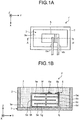
- FIG. 1A is a schematic plan view of the acoustic generator 1'
- FIG. 1B is a first cross sectional view along the line A-A' in FIG. 1A
- FIG. 1C is a second cross sectional view along the line A-A' in FIG. 1A .
- FIGS. 1A, 1B , and 1C included in FIGS. 1A, 1B , and 1C is a three-dimensional Cartesian coordinate system having a Z axis the positive direction of which extends perpendicularly upwardly and the negative direction of which extends perpendicularly downwardly.
- This Cartesian coordinate system is included in some of the drawings referred to in the following explanation.
- FIG. 1A A resin layer 7 (described later) is omitted in FIG. 1A . Also to facilitate understanding of the explanation, illustrated in FIG. 1B and FIG. 1C is the acoustic generator 1' the thickness direction of which (Z-axial direction) is exaggeratingly enlarged.
- the acoustic generator 1' includes a frame 2, a vibrating plate 3, a piezoelectric element 5, and lead wires 6a and 6b.
- the piezoelectric element 5 is provided in singularity as illustrated in FIG. 1A , but the number of the piezoelectric element 5 is not limited to one.
- the frame 2 functions as a support for supporting the vibrating plate 3 at ends of the vibrating plate 3.
- the vibrating plate 3 has a plate-like or a film-like shape the ends of which are fixed by the frame 2, to be supported in a state of being substantially flat and provided with uniform tension in the frame 2.
- the frame 2 has two frame members having the same rectangular, frame-like shape, and nipping the ends of the vibrating plate 3 therebetween, thereby allowing the frame 2 to serve as a support for supporting the vibrating plate 3.
- the vibrating plate 3 has a plate-like or a film-like shape the ends of which are nipped and fixed by the frame 2. In other words, the vibrating plate 3 is supported in a state of being substantially flat and provided with uniform tension in the frame 2.
- the vibrating plate 3 can be stably stretched by nipping the vibrating plate 3 by the two frame members. This structure is better because it improves the frequency characteristics of the acoustic generator 1' to those that are durable and do not fluctuate for a long time.
- the inner portion of the vibrating plate 3, being inner with respect to the internal circumference of the frame 2, and that is not nipped by the frame 2 and is capable of freely vibrating serves as a vibrating portion 3a.
- the vibrating portion 3a is an approximately rectangular portion that is on the inner side of the frame 2.
- the vibrating plate 3 may be made of various types of materials, such as a resin or a metal.
- the vibrating plate 3 may be a film made of a resin such as polyethylene, polyimide, and polypropylene and having a thickness of 10 micrometers to 200 micrometers. Because resin films are a material having a lower elastic modulus and a lower mechanical Q value than those of metal plates and the like, the vibrating plate 3 formed of a resin film can be bent and vibrated with a large amplitude, and enables reduction in difference between the resonance peak and the dip by increasing the width of the resonance peak and lowering the height of the resonance peak in sound pressure frequency characteristics.
- a composite material of a metal and a resin may be used as the vibrating plate 3.
- the thickness, the material, and the like of the frame 2 are not particularly limited.
- the frame 2 may be made of various types of materials such as a resin or a metal.
- the frame 2 may be preferably made of stainless steel with a thickness of 100 micrometers to 1000 micrometers, from the viewpoint of mechanical strength and high corrosion resistance.
- FIG. 1A Illustrated in FIG. 1A is the frame 2 the internal area of which has an approximately rectangular shape, but the shape may also be a polygonal shape such as a parallelogram, a trapezoid, or a regular polygon.
- the frame 2 has an approximately rectangular shape, as illustrated in FIG. 1A .
- the piezoelectric element 5 is provided by being bonded to the surface of the vibrating portion 3a, for example, and serves as an exciter that receives an application of a voltage and excites the vibrating portion 3a.
- the piezoelectric element 5 includes a laminate of four piezoelectric layers 5a, 5b, 5c, and 5d that are made of ceramic and laminated alternatingly with three internal electrode layers 5e, surface electrode layers 5f and 5g provided on the top and the bottom surfaces of the laminate, respectively, and external electrodes 5h and 5j provided on respective sides where the internal electrode layers 5e are exposed, as illustrated in FIG. 1B or FIG. 1C .
- the lead wires 6a and 6b are connected, respectively.
- the lead wires 6a and 6b are leads that receive electrical signals from outside.
- the piezoelectric element 5 has a plate-like shape the principal surfaces of which at the top and the bottom have a polygonal shape such as a rectangle or a square.
- the piezoelectric layers 5a, 5b, 5c, and 5d are polarized in the directions indicated by the arrows in FIG. 1B or 1C .
- the piezoelectric layers 5a, 5b, 5c, and 5d are polarized in opposite directions on one side and the other side in the thickness direction (Z-axial direction in FIG. 1B or 1C ), with respect to the direction of the electric field applied at a particular moment.
- the piezoelectric elements 5 When a voltage is applied to the piezoelectric element 5 via the lead wires 6a and 6b, the piezoelectric layers 5c and 5d on the side bonded on the vibrating portion 3a shrink, and the piezoelectric layers 5a and 5b on the top surface side of the piezoelectric element 5 stretch and deform, for example, at one particular moment.
- the piezoelectric element 5 By applying an alternating-current signal to the piezoelectric element 5, the piezoelectric element 5 is caused to bend and vibrate, thereby causing the vibrating portion 3a to bend and vibrate.
- the piezoelectric layers 5a and 5b on the top surface side of the piezoelectric element 5 and the piezoelectric layers 5c and 5d on the bottom surface side thereof exhibit stretching and shrinking behaviors conflicting each other. Consequently, the piezoelectric element 5 is caused to bend and vibrate in a bimorph manner, to apply fixed vibration to the vibrating portion 3a to generate sound. Because the piezoelectric element 5 is a laminated bimorph piezoelectric vibrating element and the piezoelectric element 5 itself bends and vibrates by itself, strong vibration can be generated regardless of the material of the vibrating portion 3a, for example, even with soft vibrating portion 3a, and sufficient sound pressure can be obtained with piezoelectric elements 5 of a small number.
- a principal surface of the piezoelectric element 5 is bonded to a principal surface of the vibrating portion 3a using an adhesive such as epoxy-based resin.
- Examples of materials with which the piezoelectric layers 5a, 5b, 5c, and 5d are formed include piezoelectric ceramics that have been conventionally used such as lead zirconate titanate or lead-free piezoelectric materials such as a Bi-layered compound and a tungsten bronze structure compound.
- Various types of metallic materials may be used for the internal electrode layers 5e.
- a material with a metallic component consisting of silver and palladium, and a ceramic component used in the piezoelectric layers 5a, 5b, 5c, and 5d, for example, are included, a stress caused by the difference in the thermal expansions in the piezoelectric layers 5a, 5b, 5c, and 5d and the internal electrode layers 5e can be reduced, so that the piezoelectric element 5 with no defective lamination can be achieved.
- the surface electrode layers 5f and 5g and the external electrodes 5h and 5j are formed of metal, such as silver, as a main component.
- the surface electrode layers 5f and 5g and the external electrodes 5h and 5j may contain a glass component.
- a glass component contained therein enables strong adhesion of the piezoelectric layers 5a, 5b, 5c, and 5d and the internal electrode layers 5e, to the surface electrode layers 5f and 5g or the external electrodes 5h and 5j.
- the content of the glass component is, for example, 20 percent by volume or less.
- the lead wires 6a and 6b are an example of leads. Each of the lead wires 6a and 6b has one end connected to the piezoelectric element 5 to input an electrical signal to the piezoelectric element 5.
- the lead wires 6a and 6b may be made of various types of metallic materials. When the lead wires 6a and 6b are provided using flexible wiring in which a foil made of a metal such as copper or aluminum is interposed between resin films, for example, a low-profile piezoelectric element 5 can be provided.
- the acoustic generator 1' also includes, as illustrated in FIG. 1B or FIG. 1C , the resin layer 7 that is provided covering the piezoelectric element 5 and the surface of the vibrating portion 3a on the inner side of the frame 2, and is integrated with the vibrating portion 3a and the piezoelectric element 5.
- the resin layer 7 a material such as an acrylic-based resin may be used, and the resin layer 7 is preferably formed in such a manner that a Young's modulus within a range from 1 megapascal to 1 gigapascal is achieved.
- the resin layer 7 is provided to the same height as the height of the frame 2, but the resin layer 7 may be provided to a height that is higher than the height of the frame 2.
- the resin layer 7 may not be necessarily provided to cover the piezoelectric element 5 and the surface of the vibrating portion 3a. It suffices that the resin layer 7 covers the piezoelectric element 5 and at least part of the surface of the vibrating portion 3a on the side where the piezoelectric element 5 is disposed.
- the vibrating portion 3a, the piezoelectric element 5, and the resin layer 7 are integrated, to form a composite vibrating portion that integrally vibrates.
- the piezoelectric element 5 is a laminated bimorph piezoelectric element, but the piezoelectric element 5 is not limited thereto.
- the piezoelectric element 5 may be a unimorph piezoelectric element that is a deformable piezoelectric element 5 bonded to the vibrating portion 3a.
- the vibrating portion 3a is supported substantially flat in a state of being provided with uniform tension inside the frame 2.
- the sound pressure steeply changes at a certain frequency, and the sound pressure frequency characteristics are not easily flattened.
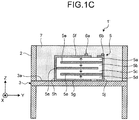
- FIG. 2 illustrates the above point.
- FIG. 2 is a a schematic illustrating an example of sound pressure frequency characteristics.
- the vibrating portion 3a is supported substantially flat in a state of being provided with uniform tension inside the frame 2.
- the peaks concentrate and degenerate at a certain frequency due to resonance of the vibrating portion 3a, so that the peaks and the dips tend to become steep and be scattered over the whole frequency regions, as illustrated in FIG. 2 .
- the frame 2 is focused on hereunder. As described above, the frame 2 is a support that supports the vibrating portion 3a while uniformly applying tension to the vibrating portion 3a. When the vibrating portion 3a vibrates, the frame 2 itself also vibrates by the resonance of the vibrating portion 3a. The frame 2 returns reflected waves to the vibrating portion 3a. Accordingly, the frame 2 can be regarded as one of constituent elements of the composite vibrating portion that integrally vibrates.
- the principal surface of the frame 2 is provided with terminals serving as connecting points from the outside to the lead wires 6a and 6b, to disturb reflected waves returned from the frame 2 to the vibrating portion 3a, by disturbing vibrating waves around the "terminals".
- the resonance frequency is made partly uneven to remove degeneration of the resonance mode and achieve distribution.
- the height of the peak P is reduced, and the peak width is increased.
- the "terminals" are provided in portions shifted from the center of the side of the frame 2, to provide the whole composite vibrating portion with an asymmetrical shape and reduce symmetry of the reflected waves.
- the resonance frequency is made partly uneven, to reduce the height of the peak P and increase the peak width.
- the frame 2 that is made asymmetrical enables distribution of the degenerate vibration mode of the frame 2 to a plurality of resonance modes, and smoothing the peak shape of the sound pressure at the resonance frequency of the frame 2.
- This structure consequently reduces the difference between the resonance peak and the dip in the sound pressure frequency characteristics of the whole composite vibrating portions, and suppresses the sound pressure frequency fluctuations as much as possible, to improve the sound quality.
- the degenerate vibration mode can be further distributed, because the temperature of the frame 2 changes in the vicinity of the "terminals” and causes expansion and contraction to cause distortion of the frame 2.
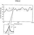
- FIG. 3A is a first schematic plan view illustrating an example of a structure of the acoustic generator 1.
- FIG. 3B is a second schematic plan view illustrating an example of the structure of the acoustic generator 1.
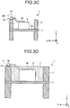
- FIG. 3C is a cross sectional view along the line B-B' in FIG. 3B .
- the resin layer 7 may be omitted in the following drawings including the schematic plan views of FIG. 3A and FIG. 3B , in the same manner as FIG. 1A , for the sake of convenience of explanation.
- the acoustic generator 1 includes terminals 2b in addition to the components of the acoustic generator 1' illustrated in FIG. 1A to FIG. 1C .
- the terminals 2b are electrode terminals serving as connecting points from the outside.
- the frame 2 is provided with one or more terminals 2b.
- FIG. 3A illustrates an example where the frame 2 is provided with a plurality of (two in this example) terminals 2b. This structure further distributes the degenerate vibration mode, and further smoothens the peak shape of the sound pressure at the resonance frequency.
- the terminals 2b When a plurality of terminals 2b are provided, it is more effective that at least one of the terminals 2b has a polarity different from the polarity of the other terminals 2b. Specifically, because the terminals 2b having different polarities have different signal components, the temperatures around the respective terminals 2b increase differently from each other. This structure enables further disturbance of the transmitted vibrating waves, and consequently causes the resonance frequency to become partly uneven.
- the terminals 2b are connected to the piezoelectric element 5 through the lead wires 6a and 6b, the terminals 2b can collect vibration around the piezoelectric element 5 via the lead wires 6a and 6b. With this structure, the vibrating waves can be further effectively disturbed around the terminals 2b.
- each of the terminals 2b is preferably provided to the frame 2, for example, with an intermediate layer 2d interposed therebetween.
- each of the terminals 2b includes, for example, a portion serving as a connecting point and formed of a metallic material, and a portion contacting the frame 2 and formed of an insulating material, and mounted to the frame 2 with the intermediate layer 2d interposed therebetween.
- FIG. 3D is a cross sectional view along the line C-C' in FIG. 3A
- FIG. 3E is an enlarged view of part H illustrated in FIG. 3D .
- the terminals 2b are fixed to the principal surface of the frame 2 with the intermediate layer 2d interposed between them.
- the terminals 2b are connected with the other ends of the lead wires 6a and 6b, respectively.
- the intermediate layer 2d is, for example, an adhesive, and serves as a member having a Young's modulus (E) lower than that of the frame 2.
- E Young's modulus
- the terminals 2b are fixed to the frame 2 with the intermediate layer 2d having a Young's modulus (E) lower than that of the frame 2 and interposed between them.
- a material having a low Young's modulus (E) generally has a small mechanical Q value, that is, has a large mechanical loss.
- such intermediate layer 2d provided absorbs vibration of the frame 2, and further disturbs vibration of the frame 2 in portions where the terminals 2b are provided.
- This structure enables further flattening of the sound pressure, and further improvement in sound quality.
- vibration of the frame 2 is attenuated when transmitted to the terminals 2b. This structure produces the effect of reducing deterioration due to vibration of the terminals 2b, and improving durability.
- the intermediate layer 2d desirably has insulating property. Vibration of the frame 2 can be more disturbed while insulation between the frame 2 and the terminals 2b are secured, by fixing the terminals 2b to the frame 2 with the insulating intermediate layer 2d interposed between them as described above.
- the intermediate layer 2d may have a structure having three layers formed of, for example, an adhesive, an insulating layer, and an adhesive.
- an adhesive for example, an adhesive, an insulating layer, and an adhesive.
- the intermediate layer 2d does not necessarily have insulating property.
- the intermediate layer 2d preferably includes pores 2da inside, that is, voids.
- the pores 2da preferably have a spherical shape to easily absorb stress and the resonance energy from all the directions in the intermediate layer 2d.
- the terminals 2b may be fixed to any of the external side surfaces of the frame 2, the principal surface of the frame 2 on the side where the piezoelectric element 5 is provided to the vibrating portion 3a and on the opposite side.
- the piezoelectric element 5 is preferably fixed to the principal surface of the frame 2 on the side where the piezoelectric element 5 is provided. This structure enables suppression of the resonance of the frame 2 caused by vibration generated from the piezoelectric element 5 and transmitted in the air, and improvement in sound quality.
- the terminals 2b are disposed on the same side as the other constituent elements such as the piezoelectric element 5 and the resin layer 7 with respect to the vibrating surface of the vibrating portion 3a.
- This structure produces the effect of reducing the symmetry of the whole composite vibrating portion with respect to the vibrating surface of the vibrating portion 3a, and distributing the resonance frequency of the whole composite vibrating portion.
- the lead wires 6a and 6b are preferably connected in a loose state between the terminals 2b and the piezoelectric element 5. Because this structure enables attenuation of vibration transmitted from the terminals 2b to the piezoelectric element 5, this structure enables reduction in noise transmitted to the piezoelectric element 5 serving as the vibrating source, and generation of clear sound with high sound quality. Because this structure also enables suppression of stress on the terminals 2b and the piezoelectric element 5, this structure improves durability, and extends the life of the product.
- the terminals 2b are preferably formed of a material softer than, that is, having a smaller elasticity than the material of the frame 2, from the viewpoint of suppressing generation of noise. This structure enables attenuation of vibration generated in the frame 2, and also enables reduction in noise transmitted to the piezoelectric element 5.
- Each of the terminals 2b may be provided with a hole portion such as a through hole.
- the terminals 2b each provided with such a hole portion are capable of distributing the degenerate vibrating mode of the frame 2, further disturbing vibration of the frame 2 in the hole portion, and disturbing reflected waves to the vibrating portion 3a. This structure enables smoothing the peak shape of the sound pressure of the whole composite vibrating portion at the resonance frequency.
- the terminals 2b may be provided to the frame 2 with a terminal plate 2a interposed between them.
- the terminal plate 2a is a substrate provided to the frame 2.
- a glass epoxy substrate or the like may be preferably used as the terminal plate 2a.
- At least one terminal 2b is provided on the terminal plate 2a as described above.
- FIG. 3 illustrates an example of the case where two terminals 2b are provided on the terminal plate 2a, but the example does not limit the number of the terminals 2b per terminal plate 2a.
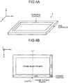
- FIG. 4A is a schematic perspective view for explaining portions of the frame 2
- FIG. 4B is a schematic plan view for explaining the portions of the frame 2.
- FIG. 4A illustrates only one of the two frame members forming the frame 2.
- end surfaces that are parallel with the XY plane in the end surfaces of the frame 2 are expressed as "principal surfaces”.
- End surfaces that are parallel with the XZ plane or the YZ plane in the end surfaces of the frame 2 are expressed as "side surfaces”.
- the ribs in the longitudinal direction or the short length direction are expressed as "sides".
- the portions in each of which a side and a side overlap each other are expressed as “corner portions” (see the diagonal region covered with diagonal lines in FIG. 4B ).
- FIG. 4B illustrates only the “center” where the side crosses the longitudinal center line CL1, but the expression is also applicable to that in the short length direction.
- FIG. 4B illustrates an example of the case where the frame 2 has a substantially rectangular shape formed of only "sides” having a straight-line shape, but the "sides" may have a curved shape as long as each of the sides is a rib having both ends.
- the region inside the frame 2 is expressed as "frame inside region”, and the region outside the frame 2 is expressed as "frame outside region”.
- the terminals 2b described above are provided to the principal surface of the frame 2, to be shifted from the center of the frame 2.
- the terminal plate 2a is provided to be shifted from the center of the sides of the frame 2 toward the corner portion of the frame 2.
- the resonance frequency is caused to become partly uneven, the peak P of the sound pressure of the resonance point is varied, and the sound pressure frequency characteristics can be flattened. Specifically, excellent sound pressure frequency characteristics can be obtained.
- the terminals 2b are provided on the principal surface side of the frame 2 serving as the side on which the sound generated by the acoustic generator 1 is transmitted, the vibrating waves induced by the sound signal are caused to easily vibrate the terminals 2b.
- the transmitted vibrating waves are caused to be easily disturbed around the terminals 2b, and consequently the resonance frequency is caused to be partly uneven.
- the peak P of the sound pressure of the resonance point is varied, and excellent sound pressure frequency characteristics can be obtained.
- the shape of the whole composite vibrating portion can be caused to become asymmetrical. This structure enables disturbance of the reflected waves from the frame 2 to the vibrating portion 3a, and reduction in symmetry of the reflected waves.
- This structure also causes the resonance frequency to be partly uneven, and varies the peak P of the sound pressure of the resonance point, to obtain excellent sound pressure frequency characteristics.
- the terminal plate 2a is provided to the frame 2, to cause the vibrating waves transmitted through the surface of the frame 2 to be reflected by a portion where the terminal plate 2a exists.
- the terminal plate 2a causes the resonance frequency to be partly uneven, and varies the peak P of the sound pressure of the resonance point, to obtain excellent sound pressure frequency characteristics.
- the terminal plate 2a can strongly disturb the vibrating waves around the terminal plate 2a, because the terminal plate 2a has a structure in which materials having different Young's moduli are scattered. This structure is more effective in causing the resonance frequency to be partly uneven.
- the shape of the whole composite vibrating portion can be caused to become asymmetrical.
- This structure enables disturbance of the reflected waves from the frame 2 to the vibrating portion 3a, and reduction in symmetry of the reflected waves. In this manner, the resonance frequency can be caused to be partly uneven. Specifically, this structure also varies the peak P of the sound pressure of the resonance point, to obtain excellent sound pressure frequency characteristics.
- the terminal plate 2a is preferably provided between the corner portion of the frame 2 and the center of the side of the frame 2.
- the reflected waves from the frame 2 to the vibrating portion 3a can be disturbed more effectively, because the shape of the whole composite vibrating portion can be caused to become asymmetrical, while avoiding the corner portion where two sides cross each other and thus having high rigidity (that is, hard to vibrate).
- the terminal plate 2a is preferably provided in the longitudinal side of the frame 2.
- the symmetry of the reflected waves can be more reduced than the case of providing the terminal plate 2a in the shorter side, and the resonance frequency can be caused to be partly uneven more effectively.
- the effects produced by the terminal plate 2a and the terminals 2b can be obtained synergistically, by providing the terminals 2b onto the terminal plate 2a as described above. Specifically, this structure enables varying the peak P of the sound pressure of the resonance point more effectively, to obtain excellent sound pressure frequency characteristics.
- the terminals 2b are capable of having respective resonance peaks different from each other, and further disturbing the vibrating waves around the terminals 2b. This structure also causes the resonance frequency to be partly uneven.
- At least one terminal 2b has a polarity different from a polarity of the other terminals 2b.
- the terminals 2b having different polarities have respective signal components different from each other, the temperatures around the respective terminals 2b increase differently from each other. This structure enables further disturbance of the vibrating waves transmitted through the terminal plate 2a, and thus causes the resonance frequency to be partly uneven.
- the terminals 2b are capable of collecting vibrations around the piezoelectric element 5 via the lead wires 6a and 6b, because the terminals 2b are connected to the piezoelectric element 5 via the lead wires 6a and 6b. This structure enables further disturbance of the vibrating waves effectively around the terminals 2b.
- the lead wires 6a and 6b (6a is not illustrated) are preferably connected in a loose state between the terminals 2b and the piezoelectric element 5.
- vibration from the terminals 2b to the piezoelectric element 5 can be attenuated, generation of noise is suppressed, and clear sound with high sound quality can be generated.
- This structure also improves durability, and extends the life of the product, because the structure suppresses stress on the terminals 2b and the piezoelectric element 5.
- the terminals 2b are preferably formed of a material softer than the material of the frame 2, from the viewpoint of suppressing generation of noise. This structure enables attenuation of vibration generated in the frame 2, and also enables reduction in noise.
- the terminals 2b are provided so as not to project into the frame outside region or the frame inside region of the frame 2, to control the degree of freedom of vibration of the terminals 2b themselves.
- This structure enables suppression of sounding from the terminals 2b, and also suppression of generation of noise.
- terminals 2b may be provided to project into the frame outside region or the frame inside region of the frame 2. This point will be explained later with reference to FIG. 5B .
- the part M1 enclosed by a two-dot chain line in FIG. 3C will be illustrated again as an enlarged view in the explanation with reference to FIG. 5F .
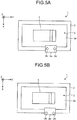
- FIG. 5A to FIG. 5D and FIG. 5H to FIG. 5J are first to seventh schematic plan views successively illustrating modifications of the terminal plate 2a or the terminals 2b.
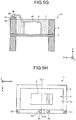
- FIG. 5E is a schematic perspective view illustrating one of modifications of the terminal plate 2a.
- FIG. 5F is a schematic cross sectional view illustrating one of modifications of the terminals 2b, and
- FIG. 5G is a cross sectional view along the line B-B' illustrating a modification of FIG. 3B .
- the terminal plate 2a may be provided to project into the frame outside region or the frame inside region of the frame 2.
- the resonance frequency is shifted in the projecting portion of the terminal plate 2a even when the frame 2 vibrates due to induction by vibration of the vibrating portion 3a, the vibrating waves of the frame 2 that is transmitted around the terminals 2b can be further disturbed.
- the reflected waves from the frame 2 to the vibrating portion 3a can be further disturbed.
- the resonance frequency is caused to be partly uneven, and the peak P of the sound pressure of the resonance point is varied, to obtain excellent sound pressure frequency characteristics.
- FIG. 5A illustrates an example of the case where the terminals 2b are provided on the terminal plate 2a so as to be located in the principal surface of the frame 2, but the terminals 2b may be provided at positions where the terminals 2b project into the frame outside region or the frame inside region of the frame 2, as illustrated in FIG. 5B . Also in this case, for the same reason as that in the case of FIG. 5A , the resonance frequency is caused to be partly uneven, and the peak P of the sound pressure of the resonance point is varied, to obtain excellent sound pressure frequency characteristics.
- the terminal plate 2a may be provided to be nonparallel with the side of the frame 2 in plan view. Specifically, the center line CL2 of the side of the frame 2 is nonparallel with the center line CL3 of the terminal plate 2a in plan view.
- the resonance frequency is further shifted in the region of the terminal plate 2a even when the frame 2 vibrates due to induction by vibration of the vibrating portion 3a, because the terminal plate 2a is nonparallel with the frame 2.
- the vibrating waves of the frame 2 that is transmitted around the terminals 2b can be further disturbed, and consequently the reflected waves from the frame 2 to the vibrating portion 3a can be further disturbed.
- the resonance frequency is caused to be partly uneven, and the peak P of the sound pressure of the resonance point is varied, to obtain excellent sound pressure frequency characteristics.
- the nonparallel structure as described above causes the shape of the composite vibrating portion to become asymmetrical. Specifically, the symmetry of the reflected waves is reduced, to cause the resonance frequency to be partly uneven.
- the terminals 2b are provided to be nonparallel with the side of the frame 2 in plan view, as illustrated in FIG. 5D .
- the line CL4 connecting the two terminals 2b is nonparallel with the center line CL2 of the side of the frame 2 in plan view.
- the resonance frequency is caused to be partly uneven, and the peak P of the sound pressure of the resonance point is varied, to obtain excellent sound pressure frequency characteristics.
- the terminal plate 2a may be provided with hole portions 2aa.
- FIG. 5E illustrates the case where the terminal plate 2a is provided with the hole portions 2aa serving as screw holes for screws SC, and the terminal plate 2a is attached to the frame 2 by fastening the hole portions 2aa with screws to screw holes 2c provided in the frame 2.
- the screws SC may also serve as the terminals 2b.
- each of the terminals 2b may be provided with a hole portion 2ba, as illustrated in FIG. 5E .
- the reflected waves from the frame 2 to the vibrating portion 3a can be further disturbed, because vibrating waves can be formed inside the holes in response to vibration.
- the joint can further disturb the vibrating waves and the reflected waves thereof.
- a counterpart member for example, the frame 2
- the joint can further disturb the vibrating waves and the reflected waves thereof.
- the circumference of the hole can be deformed with high sound pressure, such a structure is more effective for disturbing the waves and causing the resonance frequency to be partly uneven.
- the terminals 2b are preferably bonded to the terminal plate 2a using the intermediate layer 2d (bonding material such as an adhesive).
- the intermediate layer 2d bonding material such as an adhesive
- the intermediate layer 2d does not necessarily have insulating property.
- the intermediate layer 2d that is conductive may be used.
- the terminal plate 2a does not necessary have insulating property.
- the terminal plate 2a formed of metal may be used.
- the intermediate layer 2d may be a member such as a washer, as well as an adhesive.
- the terminal plate 2a as well as the terminals 2b may be bonded to the frame 2 using the intermediate layer 2d.
- terminal plate 2a is preferably provided between the corner portion of the frame 2 and the center of the side of the frame 2 in the explanation with reference to FIG. 3B , the embodiment is not limited thereto.
- the terminal plate 2a may overlap the center of the frame 2 with respect to the center line CL1. Specifically, even when the terminal plate 2a overlaps the center of the frame 2, it suffices that the center line CL5 of the terminal plate 2a is shifted from the center of the frame 2 toward the corner portion C1 or the corner portion C2.
- This structure can also at least cause the shape of the whole composite vibrating portion to be asymmetrical, and reduces and disturbs the symmetry of the reflected waves from the frame 2 to the vibrating portion 3a.
- the structure is more effective when at least the terminals 2b are also provided to be shifted from the center of the frame 2, as illustrated in FIG. 5H .
- the terminal plate 2a may be provided to overlap the corner portion (corner portion C1 in this example) of the frame 2.
- This structure can also at least cause the shape of the whole composite vibrating portion to be asymmetrical, in the same manner as in the case of FIG. 5H , and reduces and disturbs the symmetry of the reflected waves from the frame 2 to the vibrating portion 3a.
- a plurality of terminal plates 2a may be provided, as well as the terminals 2b.
- the second terminal plate 2a and subsequent terminal plates 2a may be provided as dummies that do not conduct electrical signals.
- the terminal plates 2a and the terminals 2b provided in plurality as dummies on the frame 2 can cause disturbance of the reflected waves from the frame 2 to the vibrating portion 3a.
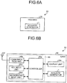
- FIG. 6A is a diagram illustrating a configuration of an acoustic generation device 20 according to one embodiment
- FIG. 6B is a diagram illustrating a configuration of an electronic device 50 according to one embodiment.
- the acoustic generation device 20 is a sound generating device such as a speaker and includes, for example, the acoustic generator 1 and a housing 30 for accommodating the acoustic generator 1, as illustrated in FIG. 6A .
- the housing 30 resonates sound produced by the acoustic generator 1 in the inside and emits the sound from a not-illustrated opening defined in the housing 30 to the outside. The provision of this housing 30 can enhance the sound pressure, for example, in a low frequency band.
- the acoustic generator 1 may be installed in different types of electronic devices 50.
- the electronic device 50 is explained to be a mobile electronic device, such as a mobile phone or a tablet terminal.
- the electronic device 50 includes an electronic circuit 60.
- the electronic circuit 60 includes, for example, a controller 50a, a communication unit 50b, a key input unit 50c, and a microphone input unit 50d.
- the electronic circuit 60 is connected to the acoustic generator 1, and serves to output an audio signal to the acoustic generator 1.
- the acoustic generator 1 generates sound based on the audio signal received from the electronic circuit 60.
- the electronic device 50 also includes a display unit 50e, an antenna 50f, and the acoustic generator 1.
- the electronic device 50 also includes a case 40 in which these devices are housed.
- FIG. 6B represents a state in which all of the devices including the controller 50a are accommodated in a single case 40
- the manner in which the devices are accommodated is not limited to this example.
- at least the electronic circuit 60 and the acoustic generator 1 are accommodated in the single case 40.
- the controller 50a is a control unit for the electronic device 50.
- the communication unit 50b exchanges data, for example, via the antenna 50f, based on the control of the controller 50a.
- the key input unit 50c is an input device for the electronic device 50, and receives operations of key inputs performed by an operator.
- the microphone input unit 50d is also an input device for the electronic device 50, and receives operations of voice inputs of an operator.
- the display unit 50e is a display output device for the electronic device 50, and outputs information to be displayed based on the control of the controller 50a.
- the acoustic generator 1 operates as a sound output device in the electronic device 50.
- the acoustic generator 1 is connected to the controller 50a in the electronic circuit 60, and receives an application of a voltage controlled by the controller 50a and outputs sound.
- the electronic device 50 is a mobile electronic device, but the type of the electronic device 50 is not limited thereto, and may be used in various types of consumer devices having a function of generating sound.
- the electronic device 50 may be a flat television or a car stereo system, for example, and may be used in various types of products with a function outputting sound, such as those with a function of "speaking", examples of which include a vacuum cleaner, a washing machine, a refrigerator, and a microwave oven.
Description
- The embodiments disclosed herein relate to an acoustic generator, an acoustic generation device, and an electronic device.
- Acoustic generators using a piezoelectric element have been conventionally known for example from documents
JP2004023436 JP2001275190 US2010/158283 andJP3160070 - In addition, such an acoustic generator can be formed thin and with a light weight in comparison with common electromagnetic speakers, because a thin film such as a resin film can be used as the vibrating plate.
- In the case of using a thin film as the vibrating plate, the thin film requires support in a state of being provided with uniform tension by being held in a thickness direction between, for example, a pair of frame members, to obtain excellent acoustic conversion efficiency.
-
US 2010/158283 A1 discloses a piezoelectric speaker including a piezoelectric thin film, electrodes formed on an upper surface or upper and lower surfaces of the piezoelectric thin film, a damping material layer formed on the lower surface of the piezoelectric thin film, and a frame attached around at least one of the piezoelectric thin film and the damping material layer using an adhesive. - Because such a conventional acoustic generator actively makes use of the resonance of the vibrating plate provided with uniform tension, the sound pressure frequency characteristics often indicate peaks (frequencies resulting in a higher sound pressure than those achieved with nearby frequencies) and dips (frequencies resulting in a lower sound pressure than those achieved with nearby frequencies), and it has been therefore difficult to achieve high quality sound.
- One aspect of the embodiment is made in consideration of the above, and an object of the embodiment is to provide an acoustic generator, an acoustic generation device, and an electronic device capable of achieving excellent sound pressure frequency characteristics. Solution to Problem
- The present invention provides an acoustic generator according to
claim 1, an acoustic generation device according to claim 8, and an electronic device according to claim 9. Further advantageous embodiments of the present invention are disclosed in the dependent claims. - With one aspect of the embodiment, excellent sound pressure frequency characteristics can be achieved.
-
-
FIG. 1A is a schematic plan view of a basic acoustic generator. -
FIG. 1B is a first cross sectional view along the line A-A' inFIG. 1A . -
FIG. 1C is a second cross sectional view along the line A-A' inFIG. 1A . -
FIG. 2 is a schematic illustrating an example of sound pressure frequency characteristics. -
FIG. 3A is a first schematic plan view illustrating an example of a structure of an acoustic generator. -
FIG. 3B is a second schematic plan view illustrating an example of the structure of the acoustic generator. -
FIG. 3C is a cross sectional view along the line B-B' inFIG. 3B . -
FIG. 3D is a cross sectional view along the line C-C' illustrating a modification ofFIG. 3A . -
FIG. 3E is an enlarged view of part H illustrated inFIG. 3D . -
FIG. 4A is a schematic perspective view for explaining portions of a frame member. -
FIG. 4B is a schematic plan view for explaining the portions of the frame member. -
FIG. 5A is a first schematic plan view illustrating a modification of a terminal plate or terminals. -
FIG. 5B is a second schematic plan view illustrating a modification of the terminal plate or the terminals. -
FIG. 5C is a third schematic plan view illustrating a modification of the terminal plate or the terminals. -
FIG. 5D is a fourth schematic plan view illustrating a modification of the terminal plate or the terminals according to the invention. -
FIG. 5E is a schematic perspective view illustrating one of modifications of the terminal plate. -
FIG. 5F is a schematic cross sectional view illustrating one of modifications of the terminal. -
FIG. 5G is a cross sectional view along the line B-B' illustrating a modification ofFIG. 3B . -
FIG. 5H is a fifth schematic plan view illustrating a modification of the terminal plate or the terminals. -
FIG. 5I is a sixth schematic plan view illustrating a modification of the terminal plate or the terminals. -
FIG. 5J is a seventh schematic plan view illustrating a modification of the terminal plate or the terminals. -
FIG. 6A is a diagram illustrating a configuration of the acoustic generation device according to one embodiment. -
FIG. 6B is a diagram illustrating a configuration of an electronic device according to one embodiment. Description of Embodiments - Embodiments of an acoustic generator, an acoustic generation device, and an electronic device that are disclosed by the present application will now be explained in detail with reference to the appended drawings. The embodiments described hereunder are not intended to limit the scope of the present invention in any way.
- Before explaining an
acoustic generator 1, a general structure of a basic acoustic generator 1' will now be explained with reference toFIGS. 1A to 1C .FIG. 1A is a schematic plan view of the acoustic generator 1',FIG. 1B is a first cross sectional view along the line A-A' inFIG. 1A , andFIG. 1C is a second cross sectional view along the line A-A' inFIG. 1A . - To facilitate understanding of the explanation, included in
FIGS. 1A, 1B , and1C is a three-dimensional Cartesian coordinate system having a Z axis the positive direction of which extends perpendicularly upwardly and the negative direction of which extends perpendicularly downwardly. This Cartesian coordinate system is included in some of the drawings referred to in the following explanation. - A resin layer 7 (described later) is omitted in
FIG. 1A . Also to facilitate understanding of the explanation, illustrated inFIG. 1B andFIG. 1C is the acoustic generator 1' the thickness direction of which (Z-axial direction) is exaggeratingly enlarged. - As illustrated in
FIG. 1A , the acoustic generator 1' includes aframe 2, a vibratingplate 3, apiezoelectric element 5, and leadwires piezoelectric element 5 is provided in singularity as illustrated inFIG. 1A , but the number of thepiezoelectric element 5 is not limited to one. - As illustrated in
FIG. 1B as an example, theframe 2 functions as a support for supporting the vibratingplate 3 at ends of the vibratingplate 3. The vibratingplate 3 has a plate-like or a film-like shape the ends of which are fixed by theframe 2, to be supported in a state of being substantially flat and provided with uniform tension in theframe 2. - In the example illustrated in
FIG. 1C , theframe 2 has two frame members having the same rectangular, frame-like shape, and nipping the ends of the vibratingplate 3 therebetween, thereby allowing theframe 2 to serve as a support for supporting the vibratingplate 3. The vibratingplate 3 has a plate-like or a film-like shape the ends of which are nipped and fixed by theframe 2. In other words, the vibratingplate 3 is supported in a state of being substantially flat and provided with uniform tension in theframe 2. - In this case, the vibrating
plate 3 can be stably stretched by nipping the vibratingplate 3 by the two frame members. This structure is better because it improves the frequency characteristics of the acoustic generator 1' to those that are durable and do not fluctuate for a long time. - The inner portion of the vibrating
plate 3, being inner with respect to the internal circumference of theframe 2, and that is not nipped by theframe 2 and is capable of freely vibrating serves as a vibratingportion 3a. The vibratingportion 3a is an approximately rectangular portion that is on the inner side of theframe 2. - The vibrating
plate 3 may be made of various types of materials, such as a resin or a metal. For example, the vibratingplate 3 may be a film made of a resin such as polyethylene, polyimide, and polypropylene and having a thickness of 10 micrometers to 200 micrometers. Because resin films are a material having a lower elastic modulus and a lower mechanical Q value than those of metal plates and the like, the vibratingplate 3 formed of a resin film can be bent and vibrated with a large amplitude, and enables reduction in difference between the resonance peak and the dip by increasing the width of the resonance peak and lowering the height of the resonance peak in sound pressure frequency characteristics. A composite material of a metal and a resin may be used as the vibratingplate 3. - The thickness, the material, and the like of the
frame 2 are not particularly limited. Theframe 2 may be made of various types of materials such as a resin or a metal. For example, theframe 2 may be preferably made of stainless steel with a thickness of 100 micrometers to 1000 micrometers, from the viewpoint of mechanical strength and high corrosion resistance. - Illustrated in
FIG. 1A is theframe 2 the internal area of which has an approximately rectangular shape, but the shape may also be a polygonal shape such as a parallelogram, a trapezoid, or a regular polygon. Explained is an example in which theframe 2 has an approximately rectangular shape, as illustrated inFIG. 1A . - The
piezoelectric element 5 is provided by being bonded to the surface of the vibratingportion 3a, for example, and serves as an exciter that receives an application of a voltage and excites the vibratingportion 3a. - The
piezoelectric element 5 includes a laminate of fourpiezoelectric layers internal electrode layers 5e,surface electrode layers external electrodes internal electrode layers 5e are exposed, as illustrated inFIG. 1B orFIG. 1C . To theexternal electrodes lead wires lead wires - The
piezoelectric element 5 has a plate-like shape the principal surfaces of which at the top and the bottom have a polygonal shape such as a rectangle or a square. Thepiezoelectric layers FIG. 1B or1C . In other words, thepiezoelectric layers FIG. 1B or1C ), with respect to the direction of the electric field applied at a particular moment. - When a voltage is applied to the
piezoelectric element 5 via thelead wires piezoelectric layers portion 3a shrink, and thepiezoelectric layers piezoelectric element 5 stretch and deform, for example, at one particular moment. By applying an alternating-current signal to thepiezoelectric element 5, thepiezoelectric element 5 is caused to bend and vibrate, thereby causing the vibratingportion 3a to bend and vibrate. - As described above, the
piezoelectric layers piezoelectric element 5 and thepiezoelectric layers piezoelectric element 5 is caused to bend and vibrate in a bimorph manner, to apply fixed vibration to the vibratingportion 3a to generate sound. Because thepiezoelectric element 5 is a laminated bimorph piezoelectric vibrating element and thepiezoelectric element 5 itself bends and vibrates by itself, strong vibration can be generated regardless of the material of the vibratingportion 3a, for example, even with soft vibratingportion 3a, and sufficient sound pressure can be obtained withpiezoelectric elements 5 of a small number. - A principal surface of the
piezoelectric element 5 is bonded to a principal surface of the vibratingportion 3a using an adhesive such as epoxy-based resin. - Examples of materials with which the
piezoelectric layers - Various types of metallic materials may be used for the
internal electrode layers 5e. When a material with a metallic component consisting of silver and palladium, and a ceramic component used in thepiezoelectric layers piezoelectric layers internal electrode layers 5e can be reduced, so that thepiezoelectric element 5 with no defective lamination can be achieved. - The
surface electrode layers external electrodes surface electrode layers external electrodes piezoelectric layers internal electrode layers 5e, to thesurface electrode layers external electrodes - The
lead wires lead wires piezoelectric element 5 to input an electrical signal to thepiezoelectric element 5. Thelead wires lead wires piezoelectric element 5 can be provided. - The acoustic generator 1' also includes, as illustrated in
FIG. 1B orFIG. 1C , theresin layer 7 that is provided covering thepiezoelectric element 5 and the surface of the vibratingportion 3a on the inner side of theframe 2, and is integrated with the vibratingportion 3a and thepiezoelectric element 5. - For the
resin layer 7, a material such as an acrylic-based resin may be used, and theresin layer 7 is preferably formed in such a manner that a Young's modulus within a range from 1 megapascal to 1 gigapascal is achieved. By embedding thepiezoelectric element 5 in theresin layer 7, an appropriate level of damper effect can be achieved, so that the resonance can be suppressed and the peaks and the dips in the sound pressure frequency characteristics can be reduced. - Furthermore, illustrated in
FIG. 1B orFIG. 1C is an example in which theresin layer 7 is provided to the same height as the height of theframe 2, but theresin layer 7 may be provided to a height that is higher than the height of theframe 2. Conversely, theresin layer 7 may not be necessarily provided to cover thepiezoelectric element 5 and the surface of the vibratingportion 3a. It suffices that theresin layer 7 covers thepiezoelectric element 5 and at least part of the surface of the vibratingportion 3a on the side where thepiezoelectric element 5 is disposed. - As described above, the vibrating
portion 3a, thepiezoelectric element 5, and theresin layer 7 are integrated, to form a composite vibrating portion that integrally vibrates. - Illustrated in
FIG. 1B orFIG. 1C is an example in which thepiezoelectric element 5 is a laminated bimorph piezoelectric element, but thepiezoelectric element 5 is not limited thereto. For example, thepiezoelectric element 5 may be a unimorph piezoelectric element that is a deformablepiezoelectric element 5 bonded to the vibratingportion 3a. - As illustrated in
FIG. 1A to FIG. 1C , the vibratingportion 3a is supported substantially flat in a state of being provided with uniform tension inside theframe 2. In such a case, because peak dips and distortions are caused by resonance induced by vibration of thepiezoelectric element 5, the sound pressure steeply changes at a certain frequency, and the sound pressure frequency characteristics are not easily flattened. -
FIG. 2 illustrates the above point.FIG. 2 is a a schematic illustrating an example of sound pressure frequency characteristics. As already described in the explanation ofFIG. 1A , the vibratingportion 3a is supported substantially flat in a state of being provided with uniform tension inside theframe 2. - In such a case, the peaks concentrate and degenerate at a certain frequency due to resonance of the vibrating
portion 3a, so that the peaks and the dips tend to become steep and be scattered over the whole frequency regions, as illustrated inFIG. 2 . - As an example, let us focus on the portion surrounded by the closed curve PD drawn with a dotted line in
FIG. 2 . With such a peak, the sound pressure becomes varied depending on the frequency, so that it becomes difficult to achieve high-quality sound. - In such a case, it is effective to take an approach of reducing the height of the peak P (see the
arrow 201 inFIG. 2 ), and of increasing the peak width (see thearrow 202 inFIG. 2 ) so that the difference between the peak P and the dip (not illustrated) is reduced, as illustrated inFIG. 2 . - The
frame 2 is focused on hereunder. As described above, theframe 2 is a support that supports the vibratingportion 3a while uniformly applying tension to the vibratingportion 3a. When the vibratingportion 3a vibrates, theframe 2 itself also vibrates by the resonance of the vibratingportion 3a. Theframe 2 returns reflected waves to the vibratingportion 3a. Accordingly, theframe 2 can be regarded as one of constituent elements of the composite vibrating portion that integrally vibrates. - For this reason, in the present example, the principal surface of the
frame 2 is provided with terminals serving as connecting points from the outside to thelead wires frame 2 to the vibratingportion 3a, by disturbing vibrating waves around the "terminals". In this manner, the resonance frequency is made partly uneven to remove degeneration of the resonance mode and achieve distribution. In this manner, the height of the peak P is reduced, and the peak width is increased. - In addition, according to the present example, the "terminals" are provided in portions shifted from the center of the side of the
frame 2, to provide the whole composite vibrating portion with an asymmetrical shape and reduce symmetry of the reflected waves. With this structure, the resonance frequency is made partly uneven, to reduce the height of the peak P and increase the peak width. - The
frame 2 that is made asymmetrical enables distribution of the degenerate vibration mode of theframe 2 to a plurality of resonance modes, and smoothing the peak shape of the sound pressure at the resonance frequency of theframe 2. This structure consequently reduces the difference between the resonance peak and the dip in the sound pressure frequency characteristics of the whole composite vibrating portions, and suppresses the sound pressure frequency fluctuations as much as possible, to improve the sound quality. In particular, when an electrical signal is input to the "terminals", the degenerate vibration mode can be further distributed, because the temperature of theframe 2 changes in the vicinity of the "terminals" and causes expansion and contraction to cause distortion of theframe 2. - The
acoustic generator 1 according to one example will be specifically explained hereinafter with reference toFIG. 3A to FIG. 5J successively. First of all,FIG. 3A is a first schematic plan view illustrating an example of a structure of theacoustic generator 1.FIG. 3B is a second schematic plan view illustrating an example of the structure of theacoustic generator 1.FIG. 3C is a cross sectional view along the line B-B' inFIG. 3B . - The
resin layer 7 may be omitted in the following drawings including the schematic plan views ofFIG. 3A and FIG. 3B , in the same manner asFIG. 1A , for the sake of convenience of explanation. - As illustrated in
FIG. 3A , theacoustic generator 1 includesterminals 2b in addition to the components of the acoustic generator 1' illustrated inFIG. 1A to FIG. 1C . Theterminals 2b are electrode terminals serving as connecting points from the outside. Theframe 2 is provided with one ormore terminals 2b.FIG. 3A illustrates an example where theframe 2 is provided with a plurality of (two in this example)terminals 2b. This structure further distributes the degenerate vibration mode, and further smoothens the peak shape of the sound pressure at the resonance frequency. - When a plurality of
terminals 2b are provided, it is more effective that at least one of theterminals 2b has a polarity different from the polarity of theother terminals 2b. Specifically, because theterminals 2b having different polarities have different signal components, the temperatures around therespective terminals 2b increase differently from each other. This structure enables further disturbance of the transmitted vibrating waves, and consequently causes the resonance frequency to become partly uneven. - Because the
terminals 2b are connected to thepiezoelectric element 5 through thelead wires terminals 2b can collect vibration around thepiezoelectric element 5 via thelead wires terminals 2b. - The
terminals 2b are preferably provided to theframe 2, for example, with anintermediate layer 2d interposed therebetween. In the case where theframe 2 is formed of a metallic material, each of theterminals 2b includes, for example, a portion serving as a connecting point and formed of a metallic material, and a portion contacting theframe 2 and formed of an insulating material, and mounted to theframe 2 with theintermediate layer 2d interposed therebetween. - This point will be explained hereinafter with reference to
FIG. 3D andFIG. 3E .FIG. 3D is a cross sectional view along the line C-C' inFIG. 3A , andFIG. 3E is an enlarged view of part H illustrated inFIG. 3D . - As illustrated in
FIG. 3D , theterminals 2b are fixed to the principal surface of theframe 2 with theintermediate layer 2d interposed between them. Theterminals 2b are connected with the other ends of thelead wires - The
intermediate layer 2d is, for example, an adhesive, and serves as a member having a Young's modulus (E) lower than that of theframe 2. As described above, theterminals 2b are fixed to theframe 2 with theintermediate layer 2d having a Young's modulus (E) lower than that of theframe 2 and interposed between them. A material having a low Young's modulus (E) generally has a small mechanical Q value, that is, has a large mechanical loss. For this reason, suchintermediate layer 2d provided absorbs vibration of theframe 2, and further disturbs vibration of theframe 2 in portions where theterminals 2b are provided. This structure enables further flattening of the sound pressure, and further improvement in sound quality. In addition, vibration of theframe 2 is attenuated when transmitted to theterminals 2b. This structure produces the effect of reducing deterioration due to vibration of theterminals 2b, and improving durability. - In the case where both the
frame 2 and theterminals 2b are formed of metal, theintermediate layer 2d desirably has insulating property. Vibration of theframe 2 can be more disturbed while insulation between theframe 2 and theterminals 2b are secured, by fixing theterminals 2b to theframe 2 with the insulatingintermediate layer 2d interposed between them as described above. - The
intermediate layer 2d may have a structure having three layers formed of, for example, an adhesive, an insulating layer, and an adhesive. When the portion of theterminals 2b contacting theframe 2 or theframe 2 is formed of an insulating material such as a resin, theintermediate layer 2d does not necessarily have insulating property. - In addition, as illustrated in
FIG. 3E , theintermediate layer 2d preferably includes pores 2da inside, that is, voids. - Because regions having different Young's moduli are scattered in the
intermediate layer 2d by providing pores 2da in theintermediate layer 2d, the resonance energy is absorbed in the regions, and the peak shape of the sound pressure at the resonance frequency is caused to become gentle. As a result, the difference between the resonance peak and the dip is reduced in the sound pressure frequency characteristics, and the frequency characteristics can be flattened. The pores 2da preferably have a spherical shape to easily absorb stress and the resonance energy from all the directions in theintermediate layer 2d. - The
terminals 2b may be fixed to any of the external side surfaces of theframe 2, the principal surface of theframe 2 on the side where thepiezoelectric element 5 is provided to the vibratingportion 3a and on the opposite side. In particular, thepiezoelectric element 5 is preferably fixed to the principal surface of theframe 2 on the side where thepiezoelectric element 5 is provided. This structure enables suppression of the resonance of theframe 2 caused by vibration generated from thepiezoelectric element 5 and transmitted in the air, and improvement in sound quality. - The
terminals 2b are disposed on the same side as the other constituent elements such as thepiezoelectric element 5 and theresin layer 7 with respect to the vibrating surface of the vibratingportion 3a. This structure produces the effect of reducing the symmetry of the whole composite vibrating portion with respect to the vibrating surface of the vibratingportion 3a, and distributing the resonance frequency of the whole composite vibrating portion. - As illustrated in
FIG. 3D , thelead wires terminals 2b and thepiezoelectric element 5. Because this structure enables attenuation of vibration transmitted from theterminals 2b to thepiezoelectric element 5, this structure enables reduction in noise transmitted to thepiezoelectric element 5 serving as the vibrating source, and generation of clear sound with high sound quality. Because this structure also enables suppression of stress on theterminals 2b and thepiezoelectric element 5, this structure improves durability, and extends the life of the product. - The
terminals 2b are preferably formed of a material softer than, that is, having a smaller elasticity than the material of theframe 2, from the viewpoint of suppressing generation of noise. This structure enables attenuation of vibration generated in theframe 2, and also enables reduction in noise transmitted to thepiezoelectric element 5. - Each of the
terminals 2b may be provided with a hole portion such as a through hole. Theterminals 2b each provided with such a hole portion are capable of distributing the degenerate vibrating mode of theframe 2, further disturbing vibration of theframe 2 in the hole portion, and disturbing reflected waves to the vibratingportion 3a. This structure enables smoothing the peak shape of the sound pressure of the whole composite vibrating portion at the resonance frequency. - As illustrated in
FIG. 3B , theterminals 2b may be provided to theframe 2 with aterminal plate 2a interposed between them. Theterminal plate 2a is a substrate provided to theframe 2. A glass epoxy substrate or the like may be preferably used as theterminal plate 2a. - At least one terminal 2b is provided on the
terminal plate 2a as described above.FIG. 3 illustrates an example of the case where twoterminals 2b are provided on theterminal plate 2a, but the example does not limit the number of theterminals 2b perterminal plate 2a. - The names of the portions of the
frame 2 will be described hereinafter with reference toFIG. 4A and FIG. 4B , from the viewpoint of facilitating understanding of the following explanation.FIG. 4A is a schematic perspective view for explaining portions of theframe 2, andFIG. 4B is a schematic plan view for explaining the portions of theframe 2.FIG. 4A illustrates only one of the two frame members forming theframe 2. - As illustrated in
FIG. 4A , end surfaces that are parallel with the XY plane in the end surfaces of theframe 2 are expressed as "principal surfaces". End surfaces that are parallel with the XZ plane or the YZ plane in the end surfaces of theframe 2 are expressed as "side surfaces". - As illustrated in
FIG. 4B , the ribs in the longitudinal direction or the short length direction are expressed as "sides". The portions in each of which a side and a side overlap each other are expressed as "corner portions" (see the diagonal region covered with diagonal lines inFIG. 4B ). - The portion where the center line CL1 of the
frame 2 and the "side" cross each other is expressed as "center".FIG. 4B illustrates only the "center" where the side crosses the longitudinal center line CL1, but the expression is also applicable to that in the short length direction. -
FIG. 4B illustrates an example of the case where theframe 2 has a substantially rectangular shape formed of only "sides" having a straight-line shape, but the "sides" may have a curved shape as long as each of the sides is a rib having both ends. - As illustrated in
FIG. 4B , the region inside theframe 2 is expressed as "frame inside region", and the region outside theframe 2 is expressed as "frame outside region". - With reference to
FIG. 3A and FIG. 3B again, theacoustic generator 1 will be explained in detail. As illustrated inFIG. 3A and FIG. 3B , theterminals 2b described above are provided to the principal surface of theframe 2, to be shifted from the center of theframe 2. In relation to this, theterminal plate 2a is provided to be shifted from the center of the sides of theframe 2 toward the corner portion of theframe 2. - First of all, the effect obtained by the above structure will be explained hereinafter with respect to the
terminals 2b. It has been already explained that theframe 2 itself also vibrates, being induced by the resonance of the vibratingportion 3a. Because theframe 2 having the above structure is provided with theterminals 2b, the vibrating waves transmitted through theframe 2 can be disturbed around theterminals 2b. - In particular, when an electrical signal is input to the
terminals 2b, because the temperature around theterminals 2b partly increases, thermal expansion is caused to easily disturb the vibrating waves. This structure enables disturbance of the reflected waves returned from theframe 2 to the vibratingportion 3a. - As a result, because the resonance frequency is caused to become partly uneven, the peak P of the sound pressure of the resonance point is varied, and the sound pressure frequency characteristics can be flattened. Specifically, excellent sound pressure frequency characteristics can be obtained.
- Because the
terminals 2b are provided on the principal surface side of theframe 2 serving as the side on which the sound generated by theacoustic generator 1 is transmitted, the vibrating waves induced by the sound signal are caused to easily vibrate theterminals 2b. - Accordingly, the transmitted vibrating waves are caused to be easily disturbed around the
terminals 2b, and consequently the resonance frequency is caused to be partly uneven. Specifically, the peak P of the sound pressure of the resonance point is varied, and excellent sound pressure frequency characteristics can be obtained. - Because the
terminals 2b are provided to be shifted from the center of theframe 2, the shape of the whole composite vibrating portion can be caused to become asymmetrical. This structure enables disturbance of the reflected waves from theframe 2 to the vibratingportion 3a, and reduction in symmetry of the reflected waves. - This structure also causes the resonance frequency to be partly uneven, and varies the peak P of the sound pressure of the resonance point, to obtain excellent sound pressure frequency characteristics.
- Then, the effect produced by the
terminal plate 2a will be explained hereinafter. Theterminal plate 2a is provided to theframe 2, to cause the vibrating waves transmitted through the surface of theframe 2 to be reflected by a portion where theterminal plate 2a exists. - Specifically, the
terminal plate 2a causes the resonance frequency to be partly uneven, and varies the peak P of the sound pressure of the resonance point, to obtain excellent sound pressure frequency characteristics. - In particular, when a glass epoxy substrate is used for the
terminal plate 2a as described above, theterminal plate 2a can strongly disturb the vibrating waves around theterminal plate 2a, because theterminal plate 2a has a structure in which materials having different Young's moduli are scattered. This structure is more effective in causing the resonance frequency to be partly uneven. - Because the
terminal plate 2a is provided to be shifted from the center of the side theframe 2 toward the corner portion of theframe 2, the shape of the whole composite vibrating portion can be caused to become asymmetrical. This structure enables disturbance of the reflected waves from theframe 2 to the vibratingportion 3a, and reduction in symmetry of the reflected waves. In this manner, the resonance frequency can be caused to be partly uneven. Specifically, this structure also varies the peak P of the sound pressure of the resonance point, to obtain excellent sound pressure frequency characteristics. - As illustrated in
FIG. 3B , theterminal plate 2a is preferably provided between the corner portion of theframe 2 and the center of the side of theframe 2. In this case, the reflected waves from theframe 2 to the vibratingportion 3a can be disturbed more effectively, because the shape of the whole composite vibrating portion can be caused to become asymmetrical, while avoiding the corner portion where two sides cross each other and thus having high rigidity (that is, hard to vibrate). - Based on the above, the
terminal plate 2a is preferably provided in the longitudinal side of theframe 2. With this structure, the symmetry of the reflected waves can be more reduced than the case of providing theterminal plate 2a in the shorter side, and the resonance frequency can be caused to be partly uneven more effectively. - The effects produced by the
terminal plate 2a and theterminals 2b can be obtained synergistically, by providing theterminals 2b onto theterminal plate 2a as described above. Specifically, this structure enables varying the peak P of the sound pressure of the resonance point more effectively, to obtain excellent sound pressure frequency characteristics. - In the case where a plurality of (two in this example)
terminals 2b are provided as illustrated inFIG. 3A , theterminals 2b are capable of having respective resonance peaks different from each other, and further disturbing the vibrating waves around theterminals 2b. This structure also causes the resonance frequency to be partly uneven. - Also in the case of providing a plurality of
terminals 2b, it is more effective that at least one terminal 2b has a polarity different from a polarity of theother terminals 2b. Specifically, because theterminals 2b having different polarities have respective signal components different from each other, the temperatures around therespective terminals 2b increase differently from each other. This structure enables further disturbance of the vibrating waves transmitted through theterminal plate 2a, and thus causes the resonance frequency to be partly uneven. - In addition, the
terminals 2b are capable of collecting vibrations around thepiezoelectric element 5 via thelead wires terminals 2b are connected to thepiezoelectric element 5 via thelead wires terminals 2b. - As illustrated in
FIG. 3C , thelead wires terminals 2b and thepiezoelectric element 5. With this structure, because vibration from theterminals 2b to thepiezoelectric element 5 can be attenuated, generation of noise is suppressed, and clear sound with high sound quality can be generated. This structure also improves durability, and extends the life of the product, because the structure suppresses stress on theterminals 2b and thepiezoelectric element 5. - The
terminals 2b are preferably formed of a material softer than the material of theframe 2, from the viewpoint of suppressing generation of noise. This structure enables attenuation of vibration generated in theframe 2, and also enables reduction in noise. - As illustrated in
FIG. 3A and FIG. 3B , theterminals 2b are provided so as not to project into the frame outside region or the frame inside region of theframe 2, to control the degree of freedom of vibration of theterminals 2b themselves. This structure enables suppression of sounding from theterminals 2b, and also suppression of generation of noise. - Conversely, the
terminals 2b may be provided to project into the frame outside region or the frame inside region of theframe 2. This point will be explained later with reference toFIG. 5B . The part M1 enclosed by a two-dot chain line inFIG. 3C will be illustrated again as an enlarged view in the explanation with reference toFIG. 5F . - Then, modifications of the
terminal plate 2a or theterminals 2b will be successively explained hereinafter, with reference toFIG. 5A to FIG. 5J .FIG. 5A to FIG. 5D andFIG. 5H to FIG. 5J are first to seventh schematic plan views successively illustrating modifications of theterminal plate 2a or theterminals 2b.FIG. 5E is a schematic perspective view illustrating one of modifications of theterminal plate 2a.FIG. 5F is a schematic cross sectional view illustrating one of modifications of theterminals 2b, andFIG. 5G is a cross sectional view along the line B-B' illustrating a modification ofFIG. 3B . - First of all, as illustrated in
FIG. 5A , theterminal plate 2a may be provided to project into the frame outside region or the frame inside region of theframe 2. In such a case, because the resonance frequency is shifted in the projecting portion of theterminal plate 2a even when theframe 2 vibrates due to induction by vibration of the vibratingportion 3a, the vibrating waves of theframe 2 that is transmitted around theterminals 2b can be further disturbed. As a result, the reflected waves from theframe 2 to the vibratingportion 3a can be further disturbed. - Specifically, the resonance frequency is caused to be partly uneven, and the peak P of the sound pressure of the resonance point is varied, to obtain excellent sound pressure frequency characteristics.
-
FIG. 5A illustrates an example of the case where theterminals 2b are provided on theterminal plate 2a so as to be located in the principal surface of theframe 2, but theterminals 2b may be provided at positions where theterminals 2b project into the frame outside region or the frame inside region of theframe 2, as illustrated inFIG. 5B . Also in this case, for the same reason as that in the case ofFIG. 5A , the resonance frequency is caused to be partly uneven, and the peak P of the sound pressure of the resonance point is varied, to obtain excellent sound pressure frequency characteristics. - As illustrated in
FIG. 5C , theterminal plate 2a may be provided to be nonparallel with the side of theframe 2 in plan view. Specifically, the center line CL2 of the side of theframe 2 is nonparallel with the center line CL3 of theterminal plate 2a in plan view. - In such a case, the resonance frequency is further shifted in the region of the
terminal plate 2a even when theframe 2 vibrates due to induction by vibration of the vibratingportion 3a, because theterminal plate 2a is nonparallel with theframe 2. With this structure, the vibrating waves of theframe 2 that is transmitted around theterminals 2b can be further disturbed, and consequently the reflected waves from theframe 2 to the vibratingportion 3a can be further disturbed. - Specifically, the resonance frequency is caused to be partly uneven, and the peak P of the sound pressure of the resonance point is varied, to obtain excellent sound pressure frequency characteristics.
- The nonparallel structure as described above causes the shape of the composite vibrating portion to become asymmetrical. Specifically, the symmetry of the reflected waves is reduced, to cause the resonance frequency to be partly uneven.
- In relation to this, according to the invention, the
terminals 2b are provided to be nonparallel with the side of theframe 2 in plan view, as illustrated inFIG. 5D . Specifically, the line CL4 connecting the twoterminals 2b is nonparallel with the center line CL2 of the side of theframe 2 in plan view. - Also in this case, for the same reason as that in the case of
FIG. 5C , the resonance frequency is caused to be partly uneven, and the peak P of the sound pressure of the resonance point is varied, to obtain excellent sound pressure frequency characteristics. - As illustrated in
FIG. 5E , theterminal plate 2a may be provided with hole portions 2aa. For example,FIG. 5E illustrates the case where theterminal plate 2a is provided with the hole portions 2aa serving as screw holes for screws SC, and theterminal plate 2a is attached to theframe 2 by fastening the hole portions 2aa with screws to screwholes 2c provided in theframe 2. For example, the screws SC may also serve as theterminals 2b. - In relation to the example illustrated in
FIG. 5E , each of theterminals 2b may be provided with a hole portion 2ba, as illustrated inFIG. 5E . In the case of providing theterminal plate 2a or theterminals 2b with holes such as the hole portions 2aa and the hole portions 2ba as described above, the reflected waves from theframe 2 to the vibratingportion 3a can be further disturbed, because vibrating waves can be formed inside the holes in response to vibration. - In the case where a joint exists between the hole and a counterpart member (for example, the frame 2), the joint can further disturb the vibrating waves and the reflected waves thereof. In addition, because the circumference of the hole can be deformed with high sound pressure, such a structure is more effective for disturbing the waves and causing the resonance frequency to be partly uneven.
- As illustrated in
FIG. 5F , theterminals 2b are preferably bonded to theterminal plate 2a using theintermediate layer 2d (bonding material such as an adhesive). In such a case, because each of theterminals 2b and theintermediate layer 2d disturbs the vibrating waves of theframe 2, the vibrating waves around theterminals 2b can be strongly disturbed synergistically. Specifically, this structure is also more effective in causing the resonance frequency to be partly uneven. - When the
terminal plate 2a has insulating property, theintermediate layer 2d does not necessarily have insulating property. Specifically, theintermediate layer 2d that is conductive may be used. When theintermediate layer 2d has insulating property, theterminal plate 2a does not necessary have insulating property. For example, theterminal plate 2a formed of metal may be used. Specifically, at least one of theintermediate layer 2d and theterminal plate 2a should have insulating property. For this reason, theintermediate layer 2d may be a member such as a washer, as well as an adhesive. As illustrated inFIG. 5G , theterminal plate 2a as well as theterminals 2b may be bonded to theframe 2 using theintermediate layer 2d. - Although the
terminal plate 2a is preferably provided between the corner portion of theframe 2 and the center of the side of theframe 2 in the explanation with reference toFIG. 3B , the embodiment is not limited thereto. - For example, as illustrated in
FIG. 5H , theterminal plate 2a may overlap the center of theframe 2 with respect to the center line CL1. Specifically, even when theterminal plate 2a overlaps the center of theframe 2, it suffices that the center line CL5 of theterminal plate 2a is shifted from the center of theframe 2 toward the corner portion C1 or the corner portion C2. - This structure can also at least cause the shape of the whole composite vibrating portion to be asymmetrical, and reduces and disturbs the symmetry of the reflected waves from the
frame 2 to the vibratingportion 3a. The structure is more effective when at least theterminals 2b are also provided to be shifted from the center of theframe 2, as illustrated inFIG. 5H . - As illustrated in
FIG. 5I , theterminal plate 2a may be provided to overlap the corner portion (corner portion C1 in this example) of theframe 2. This structure can also at least cause the shape of the whole composite vibrating portion to be asymmetrical, in the same manner as in the case ofFIG. 5H , and reduces and disturbs the symmetry of the reflected waves from theframe 2 to the vibratingportion 3a. - As illustrated in
FIG. 5J , a plurality ofterminal plates 2a may be provided, as well as theterminals 2b. In this case, the secondterminal plate 2a andsubsequent terminal plates 2a may be provided as dummies that do not conduct electrical signals. - The
terminal plates 2a and theterminals 2b provided in plurality as dummies on theframe 2 can cause disturbance of the reflected waves from theframe 2 to the vibratingportion 3a. - An acoustic generation device and an electronic device equipped with the
acoustic generator 1 according to the embodiment described above will now be described with reference toFIG. 6A and FIG. 6B. FIG. 6A is a diagram illustrating a configuration of anacoustic generation device 20 according to one embodiment, andFIG. 6B is a diagram illustrating a configuration of anelectronic device 50 according to one embodiment. These diagrams illustrate only the components required for description and do not illustrate general components. - The
acoustic generation device 20 is a sound generating device such as a speaker and includes, for example, theacoustic generator 1 and ahousing 30 for accommodating theacoustic generator 1, as illustrated inFIG. 6A . Thehousing 30 resonates sound produced by theacoustic generator 1 in the inside and emits the sound from a not-illustrated opening defined in thehousing 30 to the outside. The provision of thishousing 30 can enhance the sound pressure, for example, in a low frequency band. - The
acoustic generator 1 may be installed in different types ofelectronic devices 50. For example, inFIG. 6B described below, theelectronic device 50 is explained to be a mobile electronic device, such as a mobile phone or a tablet terminal. - As illustrated in
FIG. 6B , theelectronic device 50 includes anelectronic circuit 60. Theelectronic circuit 60 includes, for example, acontroller 50a, acommunication unit 50b, akey input unit 50c, and amicrophone input unit 50d. Theelectronic circuit 60 is connected to theacoustic generator 1, and serves to output an audio signal to theacoustic generator 1. Theacoustic generator 1 generates sound based on the audio signal received from theelectronic circuit 60. - The
electronic device 50 also includes adisplay unit 50e, anantenna 50f, and theacoustic generator 1. Theelectronic device 50 also includes acase 40 in which these devices are housed. - Although
FIG. 6B represents a state in which all of the devices including thecontroller 50a are accommodated in asingle case 40, the manner in which the devices are accommodated is not limited to this example. In the present embodiment, at least theelectronic circuit 60 and theacoustic generator 1 are accommodated in thesingle case 40. - The
controller 50a is a control unit for theelectronic device 50. Thecommunication unit 50b exchanges data, for example, via theantenna 50f, based on the control of thecontroller 50a. - The
key input unit 50c is an input device for theelectronic device 50, and receives operations of key inputs performed by an operator. Themicrophone input unit 50d is also an input device for theelectronic device 50, and receives operations of voice inputs of an operator. - The
display unit 50e is a display output device for theelectronic device 50, and outputs information to be displayed based on the control of thecontroller 50a. - The
acoustic generator 1 operates as a sound output device in theelectronic device 50. Theacoustic generator 1 is connected to thecontroller 50a in theelectronic circuit 60, and receives an application of a voltage controlled by thecontroller 50a and outputs sound. - Explained with reference to
FIG. 6B is an example in which theelectronic device 50 is a mobile electronic device, but the type of theelectronic device 50 is not limited thereto, and may be used in various types of consumer devices having a function of generating sound. Theelectronic device 50 may be a flat television or a car stereo system, for example, and may be used in various types of products with a function outputting sound, such as those with a function of "speaking", examples of which include a vacuum cleaner, a washing machine, a refrigerator, and a microwave oven.
Claims (9)
- An acoustic generator (1) comprising:a piezoelectric element (5) that receives an input of electrical signals and is caused to vibrate, the piezoelectric element having a rectangular top principal surface and a rectangular bottom principal surface;a vibrating plate (3) on which the bottom principal surface of the piezoelectric element (5) is mounted and that is caused to vibrate by the vibration of the piezoelectric element (5);a rectangular frame (2) that is provided on an external circumferential portion of the vibrating plate (3), and supports the flat vibrating plate (3); andleads (6a, 6b) that are connected to the piezoelectric element (5), and input the electrical signals to the piezoelectric element (5), the rectangular frame (2) including, on one of sides of the rectangular frame (2), a plurality of terminals (2b) serving as connection points to the leads (6a, 6b), characterised in that the vibrating plate (3) is formed of a resin film, and in that the plurality of terminals (2b) are provided such that a line connecting the centers of at least two of the terminals (2b) is nonparallel with the one side of the rectangular frame (2) in plan view.
- The acoustic generator (1) according to claim 1, wherein the terminals (2b) are arranged apart from center of the one side of the rectangular frame (2).
- The acoustic generator (1) according to any one of claim 1 or 2, wherein the rectangular frame (2) further includes a substrate (2a) provided to the rectangular frame (2), and the terminals (2b) are provided on the substrate (2a).
- The acoustic generator (1) according to claim 3, wherein the substrate (2a), provided to the rectangular frame (2), is arranged apart from center of the one side of the rectangular frame (2) toward a corner portion of the rectangular frame (2).
- The acoustic generator (1) according to claim 3 or 4, wherein the substrate (2a) is provided to be nonparallel with the one side of the rectangular frame (2) in plan view.
- The acoustic generator (1) according to any one of claims 3 to 5, wherein the substrate (2a) is provided to project into a frame outside region or a frame inside region of the rectangular frame (2).
- The acoustic generator (1) according to any one of claims 1 to 6, wherein the piezoelectric element (5) is a laminated bimorph piezoelectric element.
- An acoustic generation device (20) comprising:the acoustic generator (1) according to any one of claims 1 to 7; anda housing (30) that accommodates the acoustic generator (1).
- An electronic device (50) comprising:the acoustic generator (1) according to any one of claims 1 to 7;an electronic circuit (60) that is connected to the acoustic generator (1); anda case (40) that accommodates the electronic circuit (60) and the acoustic generator (1), whereinthe electronic device (50) has a function of producing sound from the acoustic generator (1).
Applications Claiming Priority (3)
| Application Number | Priority Date | Filing Date | Title |
|---|---|---|---|
| JP2012275132 | 2012-12-17 | ||
| JP2012280204 | 2012-12-21 | ||
| PCT/JP2013/067921 WO2014097668A1 (en) | 2012-12-17 | 2013-06-28 | Acoustic generator, acoustic genera tion device, and electronic device |
Publications (3)
| Publication Number | Publication Date |
|---|---|
| EP2947897A1 EP2947897A1 (en) | 2015-11-25 |
| EP2947897A4 EP2947897A4 (en) | 2016-11-09 |
| EP2947897B1 true EP2947897B1 (en) | 2019-05-01 |
Family
ID=50978022
Family Applications (1)
| Application Number | Title | Priority Date | Filing Date |
|---|---|---|---|
| EP13864576.7A Not-in-force EP2947897B1 (en) | 2012-12-17 | 2013-06-28 | Acoustic generator, acoustic generation device, and electronic device |
Country Status (7)
| Country | Link |
|---|---|
| US (1) | US9380365B2 (en) |
| EP (1) | EP2947897B1 (en) |
| JP (1) | JP5908994B2 (en) |
| KR (1) | KR101507747B1 (en) |
| CN (1) | CN103999482B (en) |
| TW (1) | TWI545967B (en) |
| WO (1) | WO2014097668A1 (en) |
Families Citing this family (6)
| Publication number | Priority date | Publication date | Assignee | Title |
|---|---|---|---|---|
| US9826315B2 (en) * | 2014-09-26 | 2017-11-21 | Kyocera Corporation | Acoustic generator, acoustic generation device, and electronic apparatus |
| CN105812989A (en) * | 2014-12-31 | 2016-07-27 | 鸿富锦精密工业(深圳)有限公司 | Loudspeaker |
| JP6434373B2 (en) * | 2015-06-11 | 2018-12-05 | 京セラ株式会社 | Piezoelectric actuator, piezoelectric vibration device including the same, sound generator, sound generator, electronic device |
| JP6411958B2 (en) * | 2015-06-29 | 2018-10-24 | 京セラ株式会社 | SOUND GENERATOR, SOUND GENERATOR HAVING THE SAME, AND ELECTRONIC DEVICE |
| JP7006017B2 (en) * | 2017-03-10 | 2022-01-24 | Tdk株式会社 | Vibration device |
| JP7087942B2 (en) * | 2018-11-16 | 2022-06-21 | Tdk株式会社 | Vibration devices, electronic devices, and how to drive vibration devices |
Citations (3)
| Publication number | Priority date | Publication date | Assignee | Title |
|---|---|---|---|---|
| JPS59129290U (en) * | 1983-02-18 | 1984-08-30 | 三洋電機株式会社 | speaker |
| JP3160070B2 (en) * | 1992-04-30 | 2001-04-23 | 呉羽化学工業株式会社 | Vibration-electric energy conversion element |
| KR20110137697A (en) * | 2010-06-17 | 2011-12-23 | 주식회사 이엠텍 | A sound converting apparatus |
Family Cites Families (15)
| Publication number | Priority date | Publication date | Assignee | Title |
|---|---|---|---|---|
| US1919632A (en) * | 1930-04-04 | 1933-07-25 | Rca Corp | Sound radiator |
| GB1219918A (en) * | 1968-08-08 | 1971-01-20 | Standard Telephones Cables Ltd | Improvements in and relating to moving coil transducers |
| US3697790A (en) * | 1970-12-02 | 1972-10-10 | William T Flint | Transducers having piezoelectric struts |
| JPS5379525A (en) * | 1976-12-23 | 1978-07-14 | Sony Corp | Compound diaphtagm for speakers |
| JPH0732837B2 (en) * | 1985-11-07 | 1995-04-12 | 松下電器産業株式会社 | Automatic washing machine |
| JPH0427278Y2 (en) * | 1985-12-26 | 1992-06-30 | ||
| CN1038179C (en) * | 1992-09-30 | 1998-04-22 | 星精密株式会社 | Electroacoustic transducer |
| JP3426185B2 (en) * | 2000-03-28 | 2003-07-14 | 松下電器産業株式会社 | Piezo speaker |
| JP2004023436A (en) | 2002-06-17 | 2004-01-22 | Nihon Ceratec Co Ltd | Piezoelectric loudspeaker |
| JP2004266424A (en) * | 2003-02-28 | 2004-09-24 | Citizen Electronics Co Ltd | Microspeaker |
| JP2005311415A (en) | 2004-04-16 | 2005-11-04 | Nec Tokin Corp | Acoustic vibration generation element |
| CN101119597B (en) * | 2006-08-02 | 2011-06-08 | 金大仁 | Panel type loudspeaker structure |
| KR101159734B1 (en) * | 2008-12-22 | 2012-06-28 | 한국전자통신연구원 | Piezoelectric speaker and method for forming the same |
| CN104540083B (en) | 2010-06-25 | 2018-02-23 | 京瓷株式会社 | Sound generator and speaker unit |
| JP6016945B2 (en) * | 2012-12-12 | 2016-10-26 | 京セラ株式会社 | SOUND GENERATOR, SOUND GENERATOR, AND ELECTRONIC DEVICE |
-
2013
- 2013-06-28 CN CN201380003242.XA patent/CN103999482B/en not_active Expired - Fee Related
- 2013-06-28 EP EP13864576.7A patent/EP2947897B1/en not_active Not-in-force
- 2013-06-28 US US14/647,965 patent/US9380365B2/en active Active
- 2013-06-28 WO PCT/JP2013/067921 patent/WO2014097668A1/en active Application Filing
- 2013-06-28 JP JP2014552953A patent/JP5908994B2/en not_active Expired - Fee Related
- 2013-06-28 KR KR1020137026844A patent/KR101507747B1/en active IP Right Grant
- 2013-11-28 TW TW102143376A patent/TWI545967B/en not_active IP Right Cessation
Patent Citations (3)
| Publication number | Priority date | Publication date | Assignee | Title |
|---|---|---|---|---|
| JPS59129290U (en) * | 1983-02-18 | 1984-08-30 | 三洋電機株式会社 | speaker |
| JP3160070B2 (en) * | 1992-04-30 | 2001-04-23 | 呉羽化学工業株式会社 | Vibration-electric energy conversion element |
| KR20110137697A (en) * | 2010-06-17 | 2011-12-23 | 주식회사 이엠텍 | A sound converting apparatus |
Also Published As
| Publication number | Publication date |
|---|---|
| JP5908994B2 (en) | 2016-04-26 |
| TW201427438A (en) | 2014-07-01 |
| KR20140103031A (en) | 2014-08-25 |
| US20150312661A1 (en) | 2015-10-29 |
| KR101507747B1 (en) | 2015-04-07 |
| WO2014097668A1 (en) | 2014-06-26 |
| TWI545967B (en) | 2016-08-11 |
| US9380365B2 (en) | 2016-06-28 |
| EP2947897A1 (en) | 2015-11-25 |
| CN103999482B (en) | 2017-02-22 |
| JPWO2014097668A1 (en) | 2017-01-12 |
| CN103999482A (en) | 2014-08-20 |
| EP2947897A4 (en) | 2016-11-09 |
Similar Documents
| Publication | Publication Date | Title |
|---|---|---|
| EP2947897B1 (en) | Acoustic generator, acoustic generation device, and electronic device | |
| KR101518987B1 (en) | Acoustic generator, acoustic generation device, and electronic device | |
| US9392373B2 (en) | Acoustic generator, acoustic generation device, and electronic device | |
| US9161134B2 (en) | Acoustic generator, acoustic generating device, and electronic device | |
| US9392372B2 (en) | Acoustic generator, acoustic generation device, and electronic device | |
| US9338557B2 (en) | Acoustic generator, acoustic generation device, and electronic device | |
| WO2014097862A1 (en) | Acoustic generator, acoustic generation device, and electronic device | |
| JP2014127767A (en) | Acoustic generator, acoustic generating device, and electronic apparatus | |
| US9369810B2 (en) | Acoustic generator, acoustic generation device, and electronic device | |
| JP5909169B2 (en) | SOUND GENERATOR, SOUND GENERATOR, AND ELECTRONIC DEVICE | |
| US9338558B2 (en) | Acoustic generator, acoustic generation device, and electronic device | |
| JP2014123812A (en) | Sound generator, sound generating system, and electronic apparatus | |
| JP6092618B2 (en) | SOUND GENERATOR, SOUND GENERATOR, AND ELECTRONIC DEVICE | |
| JP2014072711A (en) | Acoustic generator, acoustic generation device and electronic apparatus | |
| WO2014091813A1 (en) | Acoustic generator, acoustic generation device, and electronic device | |
| WO2014104018A1 (en) | Sound generator, sound generating apparatus, and electronic apparatus | |
| JP2014116795A (en) | Sound generator, sound generation device and electronic apparatus | |
| JP2014064149A (en) | Acoustic generator, acoustic generation apparatus, and electronic apparatus |
Legal Events
| Date | Code | Title | Description |
|---|---|---|---|
| PUAI | Public reference made under article 153(3) epc to a published international application that has entered the european phase |
Free format text: ORIGINAL CODE: 0009012 |
|
| 17P | Request for examination filed |
Effective date: 20150526 |
|
| AK | Designated contracting states |
Kind code of ref document: A1 Designated state(s): AL AT BE BG CH CY CZ DE DK EE ES FI FR GB GR HR HU IE IS IT LI LT LU LV MC MK MT NL NO PL PT RO RS SE SI SK SM TR |
|
| AX | Request for extension of the european patent |
Extension state: BA ME |
|
| RAP1 | Party data changed (applicant data changed or rights of an application transferred) |
Owner name: KYOCERA CORPORATION |
|
| DAX | Request for extension of the european patent (deleted) | ||
| A4 | Supplementary search report drawn up and despatched |
Effective date: 20161011 |
|
| RIC1 | Information provided on ipc code assigned before grant |
Ipc: H04R 1/02 20060101ALI20161005BHEP Ipc: H04R 7/04 20060101ALI20161005BHEP Ipc: H01L 41/09 20060101ALI20161005BHEP Ipc: H04R 1/06 20060101ALI20161005BHEP Ipc: H04R 1/28 20060101ALI20161005BHEP Ipc: H04R 17/00 20060101AFI20161005BHEP Ipc: H01L 41/083 20060101ALI20161005BHEP Ipc: H04M 1/03 20060101ALI20161005BHEP |
|
| STAA | Information on the status of an ep patent application or granted ep patent |
Free format text: STATUS: EXAMINATION IS IN PROGRESS |
|
| 17Q | First examination report despatched |
Effective date: 20180420 |
|
| GRAP | Despatch of communication of intention to grant a patent |
Free format text: ORIGINAL CODE: EPIDOSNIGR1 |
|
| STAA | Information on the status of an ep patent application or granted ep patent |
Free format text: STATUS: GRANT OF PATENT IS INTENDED |
|
| INTG | Intention to grant announced |
Effective date: 20181122 |
|
| RIN1 | Information on inventor provided before grant (corrected) |
Inventor name: TERAZONO, MASAKI Inventor name: KAMITANI, SATORU Inventor name: OKAMURA, TAKESHI |
|
| GRAS | Grant fee paid |
Free format text: ORIGINAL CODE: EPIDOSNIGR3 |
|
| GRAA | (expected) grant |
Free format text: ORIGINAL CODE: 0009210 |
|
| STAA | Information on the status of an ep patent application or granted ep patent |
Free format text: STATUS: THE PATENT HAS BEEN GRANTED |
|
| AK | Designated contracting states |
Kind code of ref document: B1 Designated state(s): AL AT BE BG CH CY CZ DE DK EE ES FI FR GB GR HR HU IE IS IT LI LT LU LV MC MK MT NL NO PL PT RO RS SE SI SK SM TR |
|
| REG | Reference to a national code |
Ref country code: GB Ref legal event code: FG4D |
|
| REG | Reference to a national code |
Ref country code: CH Ref legal event code: EP Ref country code: AT Ref legal event code: REF Ref document number: 1128534 Country of ref document: AT Kind code of ref document: T Effective date: 20190515 |
|
| REG | Reference to a national code |
Ref country code: DE Ref legal event code: R096 Ref document number: 602013054816 Country of ref document: DE |
|
| REG | Reference to a national code |
Ref country code: IE Ref legal event code: FG4D |
|
| REG | Reference to a national code |
Ref country code: NL Ref legal event code: MP Effective date: 20190501 |
|
| REG | Reference to a national code |
Ref country code: LT Ref legal event code: MG4D |
|
| PG25 | Lapsed in a contracting state [announced via postgrant information from national office to epo] |
Ref country code: NO Free format text: LAPSE BECAUSE OF FAILURE TO SUBMIT A TRANSLATION OF THE DESCRIPTION OR TO PAY THE FEE WITHIN THE PRESCRIBED TIME-LIMIT Effective date: 20190801 Ref country code: LT Free format text: LAPSE BECAUSE OF FAILURE TO SUBMIT A TRANSLATION OF THE DESCRIPTION OR TO PAY THE FEE WITHIN THE PRESCRIBED TIME-LIMIT Effective date: 20190501 Ref country code: FI Free format text: LAPSE BECAUSE OF FAILURE TO SUBMIT A TRANSLATION OF THE DESCRIPTION OR TO PAY THE FEE WITHIN THE PRESCRIBED TIME-LIMIT Effective date: 20190501 Ref country code: NL Free format text: LAPSE BECAUSE OF FAILURE TO SUBMIT A TRANSLATION OF THE DESCRIPTION OR TO PAY THE FEE WITHIN THE PRESCRIBED TIME-LIMIT Effective date: 20190501 Ref country code: AL Free format text: LAPSE BECAUSE OF FAILURE TO SUBMIT A TRANSLATION OF THE DESCRIPTION OR TO PAY THE FEE WITHIN THE PRESCRIBED TIME-LIMIT Effective date: 20190501 Ref country code: PT Free format text: LAPSE BECAUSE OF FAILURE TO SUBMIT A TRANSLATION OF THE DESCRIPTION OR TO PAY THE FEE WITHIN THE PRESCRIBED TIME-LIMIT Effective date: 20190901 Ref country code: ES Free format text: LAPSE BECAUSE OF FAILURE TO SUBMIT A TRANSLATION OF THE DESCRIPTION OR TO PAY THE FEE WITHIN THE PRESCRIBED TIME-LIMIT Effective date: 20190501 Ref country code: SE Free format text: LAPSE BECAUSE OF FAILURE TO SUBMIT A TRANSLATION OF THE DESCRIPTION OR TO PAY THE FEE WITHIN THE PRESCRIBED TIME-LIMIT Effective date: 20190501 Ref country code: HR Free format text: LAPSE BECAUSE OF FAILURE TO SUBMIT A TRANSLATION OF THE DESCRIPTION OR TO PAY THE FEE WITHIN THE PRESCRIBED TIME-LIMIT Effective date: 20190501 |
|
| PG25 | Lapsed in a contracting state [announced via postgrant information from national office to epo] |
Ref country code: GR Free format text: LAPSE BECAUSE OF FAILURE TO SUBMIT A TRANSLATION OF THE DESCRIPTION OR TO PAY THE FEE WITHIN THE PRESCRIBED TIME-LIMIT Effective date: 20190802 Ref country code: RS Free format text: LAPSE BECAUSE OF FAILURE TO SUBMIT A TRANSLATION OF THE DESCRIPTION OR TO PAY THE FEE WITHIN THE PRESCRIBED TIME-LIMIT Effective date: 20190501 Ref country code: LV Free format text: LAPSE BECAUSE OF FAILURE TO SUBMIT A TRANSLATION OF THE DESCRIPTION OR TO PAY THE FEE WITHIN THE PRESCRIBED TIME-LIMIT Effective date: 20190501 Ref country code: BG Free format text: LAPSE BECAUSE OF FAILURE TO SUBMIT A TRANSLATION OF THE DESCRIPTION OR TO PAY THE FEE WITHIN THE PRESCRIBED TIME-LIMIT Effective date: 20190801 |
|
| REG | Reference to a national code |
Ref country code: AT Ref legal event code: MK05 Ref document number: 1128534 Country of ref document: AT Kind code of ref document: T Effective date: 20190501 |
|
| PG25 | Lapsed in a contracting state [announced via postgrant information from national office to epo] |
Ref country code: IS Free format text: LAPSE BECAUSE OF FAILURE TO SUBMIT A TRANSLATION OF THE DESCRIPTION OR TO PAY THE FEE WITHIN THE PRESCRIBED TIME-LIMIT Effective date: 20190901 |
|
| PG25 | Lapsed in a contracting state [announced via postgrant information from national office to epo] |
Ref country code: EE Free format text: LAPSE BECAUSE OF FAILURE TO SUBMIT A TRANSLATION OF THE DESCRIPTION OR TO PAY THE FEE WITHIN THE PRESCRIBED TIME-LIMIT Effective date: 20190501 Ref country code: RO Free format text: LAPSE BECAUSE OF FAILURE TO SUBMIT A TRANSLATION OF THE DESCRIPTION OR TO PAY THE FEE WITHIN THE PRESCRIBED TIME-LIMIT Effective date: 20190501 Ref country code: CZ Free format text: LAPSE BECAUSE OF FAILURE TO SUBMIT A TRANSLATION OF THE DESCRIPTION OR TO PAY THE FEE WITHIN THE PRESCRIBED TIME-LIMIT Effective date: 20190501 Ref country code: MC Free format text: LAPSE BECAUSE OF FAILURE TO SUBMIT A TRANSLATION OF THE DESCRIPTION OR TO PAY THE FEE WITHIN THE PRESCRIBED TIME-LIMIT Effective date: 20190501 Ref country code: AT Free format text: LAPSE BECAUSE OF FAILURE TO SUBMIT A TRANSLATION OF THE DESCRIPTION OR TO PAY THE FEE WITHIN THE PRESCRIBED TIME-LIMIT Effective date: 20190501 Ref country code: DK Free format text: LAPSE BECAUSE OF FAILURE TO SUBMIT A TRANSLATION OF THE DESCRIPTION OR TO PAY THE FEE WITHIN THE PRESCRIBED TIME-LIMIT Effective date: 20190501 Ref country code: SK Free format text: LAPSE BECAUSE OF FAILURE TO SUBMIT A TRANSLATION OF THE DESCRIPTION OR TO PAY THE FEE WITHIN THE PRESCRIBED TIME-LIMIT Effective date: 20190501 |
|
| REG | Reference to a national code |
Ref country code: CH Ref legal event code: PL |
|
| REG | Reference to a national code |
Ref country code: DE Ref legal event code: R097 Ref document number: 602013054816 Country of ref document: DE |
|
| PG25 | Lapsed in a contracting state [announced via postgrant information from national office to epo] |
Ref country code: SM Free format text: LAPSE BECAUSE OF FAILURE TO SUBMIT A TRANSLATION OF THE DESCRIPTION OR TO PAY THE FEE WITHIN THE PRESCRIBED TIME-LIMIT Effective date: 20190501 Ref country code: IT Free format text: LAPSE BECAUSE OF FAILURE TO SUBMIT A TRANSLATION OF THE DESCRIPTION OR TO PAY THE FEE WITHIN THE PRESCRIBED TIME-LIMIT Effective date: 20190501 |
|
| PLBE | No opposition filed within time limit |
Free format text: ORIGINAL CODE: 0009261 |
|
| STAA | Information on the status of an ep patent application or granted ep patent |
Free format text: STATUS: NO OPPOSITION FILED WITHIN TIME LIMIT |
|
| REG | Reference to a national code |
Ref country code: BE Ref legal event code: MM Effective date: 20190630 |
|
| PG25 | Lapsed in a contracting state [announced via postgrant information from national office to epo] |
Ref country code: TR Free format text: LAPSE BECAUSE OF FAILURE TO SUBMIT A TRANSLATION OF THE DESCRIPTION OR TO PAY THE FEE WITHIN THE PRESCRIBED TIME-LIMIT Effective date: 20190501 |
|
| 26N | No opposition filed |
Effective date: 20200204 |
|
| GBPC | Gb: european patent ceased through non-payment of renewal fee |
Effective date: 20190801 |
|
| PG25 | Lapsed in a contracting state [announced via postgrant information from national office to epo] |
Ref country code: PL Free format text: LAPSE BECAUSE OF FAILURE TO SUBMIT A TRANSLATION OF THE DESCRIPTION OR TO PAY THE FEE WITHIN THE PRESCRIBED TIME-LIMIT Effective date: 20190501 Ref country code: IE Free format text: LAPSE BECAUSE OF NON-PAYMENT OF DUE FEES Effective date: 20190628 |
|
| PG25 | Lapsed in a contracting state [announced via postgrant information from national office to epo] |
Ref country code: LI Free format text: LAPSE BECAUSE OF NON-PAYMENT OF DUE FEES Effective date: 20190630 Ref country code: CH Free format text: LAPSE BECAUSE OF NON-PAYMENT OF DUE FEES Effective date: 20190630 Ref country code: SI Free format text: LAPSE BECAUSE OF FAILURE TO SUBMIT A TRANSLATION OF THE DESCRIPTION OR TO PAY THE FEE WITHIN THE PRESCRIBED TIME-LIMIT Effective date: 20190501 Ref country code: BE Free format text: LAPSE BECAUSE OF NON-PAYMENT OF DUE FEES Effective date: 20190630 Ref country code: LU Free format text: LAPSE BECAUSE OF NON-PAYMENT OF DUE FEES Effective date: 20190628 |
|
| PG25 | Lapsed in a contracting state [announced via postgrant information from national office to epo] |
Ref country code: FR Free format text: LAPSE BECAUSE OF NON-PAYMENT OF DUE FEES Effective date: 20190701 |
|
| PG25 | Lapsed in a contracting state [announced via postgrant information from national office to epo] |
Ref country code: GB Free format text: LAPSE BECAUSE OF NON-PAYMENT OF DUE FEES Effective date: 20190801 |
|
| PG25 | Lapsed in a contracting state [announced via postgrant information from national office to epo] |
Ref country code: CY Free format text: LAPSE BECAUSE OF FAILURE TO SUBMIT A TRANSLATION OF THE DESCRIPTION OR TO PAY THE FEE WITHIN THE PRESCRIBED TIME-LIMIT Effective date: 20190501 |
|
| PG25 | Lapsed in a contracting state [announced via postgrant information from national office to epo] |
Ref country code: HU Free format text: LAPSE BECAUSE OF FAILURE TO SUBMIT A TRANSLATION OF THE DESCRIPTION OR TO PAY THE FEE WITHIN THE PRESCRIBED TIME-LIMIT; INVALID AB INITIO Effective date: 20130628 Ref country code: MT Free format text: LAPSE BECAUSE OF FAILURE TO SUBMIT A TRANSLATION OF THE DESCRIPTION OR TO PAY THE FEE WITHIN THE PRESCRIBED TIME-LIMIT Effective date: 20190501 |
|
| PGFP | Annual fee paid to national office [announced via postgrant information from national office to epo] |
Ref country code: DE Payment date: 20210602 Year of fee payment: 9 |
|
| PG25 | Lapsed in a contracting state [announced via postgrant information from national office to epo] |
Ref country code: MK Free format text: LAPSE BECAUSE OF FAILURE TO SUBMIT A TRANSLATION OF THE DESCRIPTION OR TO PAY THE FEE WITHIN THE PRESCRIBED TIME-LIMIT Effective date: 20190501 |
|
| REG | Reference to a national code |
Ref country code: DE Ref legal event code: R119 Ref document number: 602013054816 Country of ref document: DE |
|
| PG25 | Lapsed in a contracting state [announced via postgrant information from national office to epo] |
Ref country code: DE Free format text: LAPSE BECAUSE OF NON-PAYMENT OF DUE FEES Effective date: 20230103 |