JP5904697B2 - Adsorption heat pump - Google Patents
Adsorption heat pump Download PDFInfo
- Publication number
- JP5904697B2 JP5904697B2 JP2009528628A JP2009528628A JP5904697B2 JP 5904697 B2 JP5904697 B2 JP 5904697B2 JP 2009528628 A JP2009528628 A JP 2009528628A JP 2009528628 A JP2009528628 A JP 2009528628A JP 5904697 B2 JP5904697 B2 JP 5904697B2
- Authority
- JP
- Japan
- Prior art keywords
- heat
- adsorption
- temperature
- regenerator
- pump system
- Prior art date
- Legal status (The legal status is an assumption and is not a legal conclusion. Google has not performed a legal analysis and makes no representation as to the accuracy of the status listed.)
- Active
Links
Images

Classifications
-
- F—MECHANICAL ENGINEERING; LIGHTING; HEATING; WEAPONS; BLASTING
- F25—REFRIGERATION OR COOLING; COMBINED HEATING AND REFRIGERATION SYSTEMS; HEAT PUMP SYSTEMS; MANUFACTURE OR STORAGE OF ICE; LIQUEFACTION SOLIDIFICATION OF GASES
- F25B—REFRIGERATION MACHINES, PLANTS OR SYSTEMS; COMBINED HEATING AND REFRIGERATION SYSTEMS; HEAT PUMP SYSTEMS
- F25B27/00—Machines, plants or systems, using particular sources of energy
- F25B27/002—Machines, plants or systems, using particular sources of energy using solar energy
- F25B27/007—Machines, plants or systems, using particular sources of energy using solar energy in sorption type systems
-
- F—MECHANICAL ENGINEERING; LIGHTING; HEATING; WEAPONS; BLASTING
- F25—REFRIGERATION OR COOLING; COMBINED HEATING AND REFRIGERATION SYSTEMS; HEAT PUMP SYSTEMS; MANUFACTURE OR STORAGE OF ICE; LIQUEFACTION SOLIDIFICATION OF GASES
- F25B—REFRIGERATION MACHINES, PLANTS OR SYSTEMS; COMBINED HEATING AND REFRIGERATION SYSTEMS; HEAT PUMP SYSTEMS
- F25B17/00—Sorption machines, plants or systems, operating intermittently, e.g. absorption or adsorption type
- F25B17/08—Sorption machines, plants or systems, operating intermittently, e.g. absorption or adsorption type the absorbent or adsorbent being a solid, e.g. salt
-
- F—MECHANICAL ENGINEERING; LIGHTING; HEATING; WEAPONS; BLASTING
- F28—HEAT EXCHANGE IN GENERAL
- F28D—HEAT-EXCHANGE APPARATUS, NOT PROVIDED FOR IN ANOTHER SUBCLASS, IN WHICH THE HEAT-EXCHANGE MEDIA DO NOT COME INTO DIRECT CONTACT
- F28D20/00—Heat storage plants or apparatus in general; Regenerative heat-exchange apparatus not covered by groups F28D17/00 or F28D19/00
- F28D20/003—Heat storage plants or apparatus in general; Regenerative heat-exchange apparatus not covered by groups F28D17/00 or F28D19/00 using thermochemical reactions
-
- F—MECHANICAL ENGINEERING; LIGHTING; HEATING; WEAPONS; BLASTING
- F25—REFRIGERATION OR COOLING; COMBINED HEATING AND REFRIGERATION SYSTEMS; HEAT PUMP SYSTEMS; MANUFACTURE OR STORAGE OF ICE; LIQUEFACTION SOLIDIFICATION OF GASES
- F25B—REFRIGERATION MACHINES, PLANTS OR SYSTEMS; COMBINED HEATING AND REFRIGERATION SYSTEMS; HEAT PUMP SYSTEMS
- F25B2400/00—General features or devices for refrigeration machines, plants or systems, combined heating and refrigeration systems or heat-pump systems, i.e. not limited to a particular subgroup of F25B
- F25B2400/24—Storage receiver heat
-
- F—MECHANICAL ENGINEERING; LIGHTING; HEATING; WEAPONS; BLASTING
- F28—HEAT EXCHANGE IN GENERAL
- F28D—HEAT-EXCHANGE APPARATUS, NOT PROVIDED FOR IN ANOTHER SUBCLASS, IN WHICH THE HEAT-EXCHANGE MEDIA DO NOT COME INTO DIRECT CONTACT
- F28D20/00—Heat storage plants or apparatus in general; Regenerative heat-exchange apparatus not covered by groups F28D17/00 or F28D19/00
- F28D20/0034—Heat storage plants or apparatus in general; Regenerative heat-exchange apparatus not covered by groups F28D17/00 or F28D19/00 using liquid heat storage material
- F28D20/0039—Heat storage plants or apparatus in general; Regenerative heat-exchange apparatus not covered by groups F28D17/00 or F28D19/00 using liquid heat storage material with stratification of the heat storage material
-
- Y—GENERAL TAGGING OF NEW TECHNOLOGICAL DEVELOPMENTS; GENERAL TAGGING OF CROSS-SECTIONAL TECHNOLOGIES SPANNING OVER SEVERAL SECTIONS OF THE IPC; TECHNICAL SUBJECTS COVERED BY FORMER USPC CROSS-REFERENCE ART COLLECTIONS [XRACs] AND DIGESTS
- Y02—TECHNOLOGIES OR APPLICATIONS FOR MITIGATION OR ADAPTATION AGAINST CLIMATE CHANGE
- Y02A—TECHNOLOGIES FOR ADAPTATION TO CLIMATE CHANGE
- Y02A30/00—Adapting or protecting infrastructure or their operation
- Y02A30/27—Relating to heating, ventilation or air conditioning [HVAC] technologies
-
- Y—GENERAL TAGGING OF NEW TECHNOLOGICAL DEVELOPMENTS; GENERAL TAGGING OF CROSS-SECTIONAL TECHNOLOGIES SPANNING OVER SEVERAL SECTIONS OF THE IPC; TECHNICAL SUBJECTS COVERED BY FORMER USPC CROSS-REFERENCE ART COLLECTIONS [XRACs] AND DIGESTS
- Y02—TECHNOLOGIES OR APPLICATIONS FOR MITIGATION OR ADAPTATION AGAINST CLIMATE CHANGE
- Y02B—CLIMATE CHANGE MITIGATION TECHNOLOGIES RELATED TO BUILDINGS, e.g. HOUSING, HOUSE APPLIANCES OR RELATED END-USER APPLICATIONS
- Y02B30/00—Energy efficient heating, ventilation or air conditioning [HVAC]
-
- Y—GENERAL TAGGING OF NEW TECHNOLOGICAL DEVELOPMENTS; GENERAL TAGGING OF CROSS-SECTIONAL TECHNOLOGIES SPANNING OVER SEVERAL SECTIONS OF THE IPC; TECHNICAL SUBJECTS COVERED BY FORMER USPC CROSS-REFERENCE ART COLLECTIONS [XRACs] AND DIGESTS
- Y02—TECHNOLOGIES OR APPLICATIONS FOR MITIGATION OR ADAPTATION AGAINST CLIMATE CHANGE
- Y02E—REDUCTION OF GREENHOUSE GAS [GHG] EMISSIONS, RELATED TO ENERGY GENERATION, TRANSMISSION OR DISTRIBUTION
- Y02E60/00—Enabling technologies; Technologies with a potential or indirect contribution to GHG emissions mitigation
- Y02E60/14—Thermal energy storage
-
- Y—GENERAL TAGGING OF NEW TECHNOLOGICAL DEVELOPMENTS; GENERAL TAGGING OF CROSS-SECTIONAL TECHNOLOGIES SPANNING OVER SEVERAL SECTIONS OF THE IPC; TECHNICAL SUBJECTS COVERED BY FORMER USPC CROSS-REFERENCE ART COLLECTIONS [XRACs] AND DIGESTS
- Y02—TECHNOLOGIES OR APPLICATIONS FOR MITIGATION OR ADAPTATION AGAINST CLIMATE CHANGE
- Y02E—REDUCTION OF GREENHOUSE GAS [GHG] EMISSIONS, RELATED TO ENERGY GENERATION, TRANSMISSION OR DISTRIBUTION
- Y02E70/00—Other energy conversion or management systems reducing GHG emissions
- Y02E70/30—Systems combining energy storage with energy generation of non-fossil origin
Landscapes
- Engineering & Computer Science (AREA)
- Mechanical Engineering (AREA)
- Physics & Mathematics (AREA)
- Thermal Sciences (AREA)
- General Engineering & Computer Science (AREA)
- General Chemical & Material Sciences (AREA)
- Chemical Kinetics & Catalysis (AREA)
- Chemical & Material Sciences (AREA)
- Life Sciences & Earth Sciences (AREA)
- Sustainable Development (AREA)
- Sustainable Energy (AREA)
- Sorption Type Refrigeration Machines (AREA)
- Central Heating Systems (AREA)
Description
本発明は、吸着式ヒートポンプ若しくは吸着式冷凍機、及び効率的な運転に適した蓄熱器に関する。 The present invention relates to an adsorption heat pump or an adsorption refrigerator, and a heat accumulator suitable for efficient operation.
吸着式ヒートポンプ及び吸着式冷凍機におけるCOP(coefficient of performance=動作係数)、つまり必要とされる作動熱に対する有効熱若しくは有効低温の比率は、同一のサイクル条件で作動する吸収式システムに比べて一般的に低い。熱力学的な解析(例えば、Meunier氏等、1996年、1997年1998年)により明らかなように、吸着は吸着器を熱源若しくはヒートシンクに接続した場合に一定の温度で生じている。 COP (coefficient of performance) in adsorption heat pumps and adsorption refrigerators, that is, the ratio of effective heat or effective low temperature to the required operating heat is generally compared to absorption systems operating under the same cycle conditions Low. As is apparent from thermodynamic analysis (eg, Meunier et al., 1996, 1997, 1998), adsorption occurs at a constant temperature when the adsorber is connected to a heat source or heat sink.
例えば冷凍機において、吸着器の温度はサイクルの経過中に最大の離脱温度と最低の吸着温度との間で変動し、吸着熱は周囲に放出されている(例えば冷却塔における再冷却)。しかしながら作動熱源(ガスバーナー或いはソーラーシステム)は熱を一定の温度レベルで供給している。エントロピー値は吸着器の最も低温状態(離脱過程の開始時)で最大である。このことは再冷却でも同じである。再冷器は一般的に一定の温度レベルに保たれ、エントロピー値は吸着器が最も高い温度状態にある場合に吸着過程の開始時に最大である。 For example, in a refrigerator, the temperature of the adsorber fluctuates between the maximum desorption temperature and the minimum adsorption temperature during the course of the cycle, and the heat of adsorption is released to the environment (eg, recooling in a cooling tower). However, the operating heat source (gas burner or solar system) supplies heat at a constant temperature level. The entropy value is greatest at the lowest temperature of the adsorber (at the start of the detachment process). The same is true for recooling. The recooler is generally kept at a constant temperature level and the entropy value is maximum at the beginning of the adsorption process when the adsorber is at the highest temperature state.
種々の吸着サイクルにおけるエントロピー値は、フランス国の作業グループのMeunierやPons氏等によって研究されている(F.Meunier、F.Poyelle、M.D.LeVan氏等の論文、「Second Law Analysis of Adsorption Refrigeration Cycles: The Role of Thermal Coupling Entropy Production( Applied Thermal Engineering 17, 43-55, 1997)」及び、M.Pons 、F.Poyelle氏等の論文「 Adsorptive machines with advanced cycles for heat pumping and cooling applications( Internat. Jounal of Refrigeration 22, 27-37, 1999)」、参照)。この場合に、熱回収を最適にすると、エントロピー値は低く、COPは著しく高くなっている。目的は常に、吸着器をあらゆる運転状態で熱源若しくはヒートシンクに対するできるだけ低い温度差で作動させることにある。実際に、吸着器から所望の出力を取り出すために必要な温度差は最小になっている。 Entropy values for various adsorption cycles have been studied by French working groups such as Meunier and Pons (F.Meunier, F.Poyelle, MDLeVan et al., “Second Law Analysis of Adsorption Refrigeration Cycles: The Role of Thermal Coupling Entropy Production (Applied Thermal Engineering 17, 43-55, 1997) '' and a paper by M. Pons, F. Poyelle et al. `` Adsorptive machines with advanced cycles for heat pumping and cooling applications (Internat. Jounal of Refrigeration 22, 27-37, 1999) ”). In this case, when heat recovery is optimized, the entropy value is low and the COP is significantly high. The aim is always to operate the adsorber at all operating conditions with the lowest possible temperature difference with respect to the heat source or heat sink. In fact, the temperature difference required to extract the desired output from the adsorber is minimal.
上記論文には、熱回収の実施のための2つの手段を示してある。第1に複数の吸着器を連結して、すでに完全に離脱されている吸着器において最大の温度レベルで解放された熱は、ちょうど離脱過程が開始された別の吸着器内で離脱のために用いられる。第2に2つの吸着器を備えた回路内でのサーマルウエブ(US 4694659号明細書)の実施である。
この場合に、1つの流体回路内で前後に接続された両方の吸着器は温度勾配を生ぜしめており、流れ方向で吸着作動の吸着器と離脱作動の吸着器との間に再熱器(高温・熱源)を接続してあり、離脱作動の吸着器と吸着作動の吸着器との間に再冷器(中間温度・ヒートシンク)を接続してある。離脱動作と吸着動作との切り換えのために、流体の流れ方向は転向され、かつ再熱器及び再冷器の通過流は、再び前述の通過流順序を得るために切り換えられる。
The above paper shows two means for carrying out heat recovery. First, by connecting multiple adsorbers, the heat released at the maximum temperature level in an adsorber that has already been completely desorbed is just for desorption in another adsorber where the desorption process has just started. Used. Second is the implementation of a thermal web (US 4694659) in a circuit with two adsorbers.
In this case, both the adsorbers connected back and forth in one fluid circuit generate a temperature gradient, and a reheater (high temperature) is interposed between the adsorbing adsorber and the adsorbing adsorber in the flow direction. -A heat source) is connected, and a recooler (intermediate temperature, heat sink) is connected between the adsorber for separation operation and the adsorber for adsorption operation. In order to switch between the detachment operation and the adsorption operation, the flow direction of the fluid is redirected, and the reheater and recooler pass flows are switched again to obtain the aforementioned flow sequence.
サーマルウエブの欠点は、COPの有効な増大のためには温度勾配を急激にして、これによって吸着段階中に熱移送流体が最大の吸着温度の吸着器を流過するようにすることである(再熱に供給される熱量は減少される)。急激な温度勾配は、すべての時点で吸着器の一部分のみが作動し(つまり、吸着し)、吸着器の大部分がすでに完全に吸着しているか若しくは吸着作動を開始していないことを意味している。このことは冷凍機の比出力(specific cooling power=SCP)にとって不都合である。したがってーマルウエブにおいては、高いCOPを得ることと高い比出力を得ることとは相反することになる。さらにサーマルウエブにおいて、互いに連結された吸着器は互いに直列に流過されねばならず、これによって熱媒(熱移送媒体)のための流路は長くなり、圧力損失及びポンプエネルギー消費量は大きくなっている。このような問題は、US 4694659号明細書に記載の発明の出願から20年を経ているにもかかわらず解決されるまでには至っていない。 The disadvantage of thermal webs is that the temperature gradient is abrupt for an effective increase in COP, thereby allowing the heat transfer fluid to flow through the adsorber at the maximum adsorption temperature during the adsorption phase ( The amount of heat supplied for reheating is reduced). A steep temperature gradient means that only a portion of the adsorber is operating (ie, adsorbing) at all points in time, and that most of the adsorber is already fully adsorbing or has not started the adsorption operation. ing. This is inconvenient for the specific cooling power (SCP) of the refrigerator. Therefore, in the multi-web, obtaining a high COP is contrary to obtaining a high specific power. Furthermore, in the thermal web, the adsorbers connected to each other must flow in series with each other, which increases the flow path for the heat medium (heat transfer medium) and increases the pressure loss and the pump energy consumption. ing. Such a problem has not yet been solved even though 20 years have passed since the application of the invention described in US Pat. No. 4,694,659.
2つよりも多くの吸着器間での熱回収器を備えた装置における欠点は、互いに熱絶縁すべき吸着器の運転のための高い装備費用にある。高いCOPを得るためには吸着器の数を増大することになり、吸着器の数の増大は冷凍機若しくはヒートポンプのコストの増大につながっている。 A disadvantage of an apparatus with a heat recovery unit between more than two adsorbers is the high equipment costs for the operation of adsorbers that are to be thermally insulated from one another. In order to obtain a high COP, the number of adsorbers is increased, and the increase in the number of adsorbers leads to an increase in the cost of a refrigerator or a heat pump.
吸着式冷凍機の従来技術においては、圧縮式冷凍機の技術に比べて特に吸着器の比出力(SCP)を著しく高めなければならない。さらに多くの使用領域において吸着機のCOPを高めて、例えば作動熱の形成に際して化石燃料による一次エネルギーの利点を圧縮器に比べて達成する必要がある。 In the conventional technology of adsorption chillers, the specific output (SCP) of the adsorber must be significantly increased compared to the technology of compression chillers. Furthermore, the COP of the adsorber must be increased in many areas of use to achieve the primary energy advantage of fossil fuels compared to compressors, for example in the formation of operating heat.
近年、高い比出力を得るための開発が行われている。例えば、SorTech AG社により、アルミニウム上にゼオライトを結晶化させることによって熱交換器をコーティングする方法が提案されている。該方法は、DE 102004052979 A1号明細書に、ゼオライト層で被覆されたサブストレートの形成のための方法として記載されている。ゼオライトと熱交換器との間の密な熱接触及び薄いゼオライト層によって、熱交換器の吸着出力は、ゼオライト・ペレットの敷設及び接着に比べて著しく高められる。しかしながら比出力のこのような改善はCOPの低下を甘受することになる。つまり薄いゼオライトに基づき、熱交換器に対する吸着剤の質量比並びに吸着可能な熱と感知可能な熱の熱比は、ゼオライト塗布層を備えるシステムよりも小さくなっている。小さい熱比にとって高い比出力を可能にして、COPを著しく増大させる必要がある。離脱時に吸着器に供給される感知可能な熱の回収、並びに外部の熱源若しくはヒートポンプに吸着器を接続することによりエントロピー値を低下させることも記載してある。 In recent years, development has been carried out to obtain a high specific output. For example, SorTech AG has proposed a method of coating a heat exchanger by crystallizing zeolite on aluminum. The method is described in DE 102004052979 A1 as a method for the formation of a substrate coated with a zeolite layer. Due to the close thermal contact between the zeolite and the heat exchanger and the thin zeolite layer, the adsorption power of the heat exchanger is significantly increased compared to the laying and bonding of the zeolite pellets. However, such an improvement in specific power will accept the drop in COP. That is, based on thin zeolite, the mass ratio of the adsorbent to the heat exchanger and the heat ratio of the adsorbable heat to the detectable heat are lower than in the system with the zeolite coating layer. There is a need to significantly increase the COP, allowing high specific power for small heat ratios. It also describes the recovery of the sensible heat supplied to the adsorber upon detachment and the reduction of the entropy value by connecting the adsorber to an external heat source or heat pump.
DE 19908666 A1号明細書には、従来の吸着器を吸着により離脱温度に加熱可能な吸着式ヒートポンプ及び冷凍機を記載してあり、該吸着式ヒートポンプ及び冷凍機は温度が、エネルギー蓄え部(アキュムレータ)として層状に形成された蓄熱器(層状蓄熱器)を用いて蒸発器と圧縮器との間で熱回収を行うようになっている。ここに記載の吸着式ヒートポンプにおいて、両方の吸着器はサーマルウエブによって作動されるようになっている。各吸着器には、蒸発器及び圧縮器の機能を交互に担う構成部分が配設されている。ヒートポンプの特殊な構造に基づき吸着器と蒸発器若しくは圧縮器との間の弁は省略され、前記構成部分が蒸発器機能と圧縮器機能との切り換えに際して温度の適切な切り換えを行うようになっている。各吸着器に配設された両方の構成部分がその機能を同時に切り換えるので、該両方の構成部分間での熱回収が可能になっている。 DE 19908666 A1 describes an adsorption heat pump and a refrigerator that can heat a conventional adsorber to a desorption temperature by adsorption. The adsorption heat pump and the refrigerator have an energy storage unit (accumulator). ) Is used to recover heat between the evaporator and the compressor using a layered regenerator (layered regenerator). In the adsorption heat pump described here, both adsorbers are actuated by a thermal web. Each adsorber is provided with components that alternately function as an evaporator and a compressor. Based on the special structure of the heat pump, the valve between the adsorber and the evaporator or the compressor is omitted, and the component performs an appropriate switching of the temperature when switching between the evaporator function and the compressor function. Yes. Since both components disposed in each adsorber switch their functions simultaneously, heat recovery between both components is possible.
層状蓄熱器は、例えば、DE 3905874 C2号明細書、DE 10212688 A1号明細書(Fa. Solvis)、並びにEP 1076219 B1号明細書(Fa. Sailer)により公知である。太陽熱収集器からの熱の成層化並びに暖房及び家庭用水のための熱の供給を目的としているために、層状蓄熱器は、該層状蓄熱器の選ばれた高さ若しくは層又は段から流体を温度に依存して取り出すための装置を備えていない。 Layered regenerators are known, for example, from DE 3905874 C2, DE 10212688 A1 (Fa. Solvis), and EP 1076219 B1 (Fa. Sailer). For the purpose of stratifying the heat from a solar collector and supplying heat for heating and domestic water, a stratified regenerator is used to heat a fluid from a selected height or layer or stage of the stratified regenerator. There is no device for taking out depending on.
本発明の課題は、簡単に実現可能な吸着式ヒートポンプを提供して、該吸着式ヒートポンプができるだけ高いCOP及び同時に高い比出力を有しているようにすることである。さらに本発明の課題は、高いCOP及び高い比出力を有する吸着式ヒートポンプの運転のための方法を提供することである。 The object of the present invention is to provide an adsorption heat pump that can be realized easily, so that the adsorption heat pump has as high a COP as possible and at the same time a high specific power. It is a further object of the present invention to provide a method for operation of an adsorption heat pump having a high COP and a high specific power.
前記課題を解決するために、本発明の構成では、吸着式ヒートポンプを含む装置であって、吸着器及び蓄熱器若しくは蓄熱器を備える形式のものにおいて、次の構成を有しており;前記蓄熱器内に異なる温度レベル若しくは種々の温度レベルの熱を同時に蓄えるようになっており、吸着時に解放された吸着熱は、後の離脱のために利用されない場合にヒートシンクに放出されるようになっており、前記離脱のために利用すべき吸着熱は、前記蓄熱器内に、吸着温度に依存した温度で蓄えられるようになっており、離脱温度は、少なくとも部分的に前記蓄熱器から所望の温度で取り出されるようになっており、熱源、特に太陽熱収集器を設けてあり、該熱源により、前記離脱に必要な熱量若しくは熱流量が、前記蓄熱器内で先行の離脱サイクルによって達成されている温度レベルよりも高い温度レベルで形成若しくは発生され、及び/又は、前記蓄熱器内に必要な量では生じていない熱量若しくは熱流量が形成されるようになっている。A及び/又はBなる記載はA及びBのうちの少なくともいずれか1つを意味する。この場合に重要なことは、1つの蓄熱器の内部に、異なる温度レベルの熱を同時に若しくは一様に蓄えられるようになっていることである。このことは、異なる温度レベルの熱が混合を生ぜしめることなく1つの蓄熱器内に蓄えられ、1つの温度レベルのみが存在していることを意味している。 In order to solve the above-described problems, the configuration of the present invention is an apparatus including an adsorption heat pump, and includes an adsorber and a heat accumulator or a heat accumulator, and has the following configuration; Heat of different temperature levels or various temperature levels is stored in the vessel at the same time, and the heat of adsorption released during adsorption is released to the heat sink when it is not used for subsequent separation. The adsorption heat to be used for the desorption is stored in the heat accumulator at a temperature depending on the adsorption temperature, and the desorption temperature is at least partially from the heat accumulator at a desired temperature. A heat source, in particular a solar heat collector, by which the amount of heat or heat flow required for the detachment is preceded by a previous detachment cycle in the regenerator. Thus formed or generated at a higher temperature level than the temperature level has been achieved, and / or the amount of heat or heat flow does not occur in an amount required in the heat accumulator is adapted to be formed. The description of A and / or B means at least one of A and B. The important case, the interior of a single regenerator is that it is adapted to be stored simultaneously or uniformly different temperature levels of heat. This means that heat at different temperature levels is stored in one regenerator without causing mixing and there is only one temperature level.
吸着温度は、吸着に際して解放される熱が生じる温度を意味している。これは、熱を蓄熱器に供給する温度ではない。むしろ熱は常に低い温度で蓄熱器に供給される。熱伝導にとって常に温度差を必要としている。必要な温度差の大きさは、熱を蓄熱器へ移送する冷媒と吸着器との間の熱抵抗、及び所定の反応速度に依存している。解放された熱をできるだけ高い温度で蓄えて、ひいてはCOPを高めるためには、吸着熱を蓄熱器へ移送する冷媒の温度と蓄熱器に蓄えられる熱の温度との差をできるだけ小さくする必要がある。熱を蓄熱器に蓄える温度は、吸着温度に依存している。装置の構造に応じて、冷媒の熱の移送の際の冷却は熱損失に起因している。 The adsorption temperature means a temperature at which heat released during adsorption is generated. This is not the temperature at which heat is supplied to the regenerator. Rather, heat is always supplied to the regenerator at a low temperature. A temperature difference is always required for heat conduction. The magnitude of the required temperature difference depends on the thermal resistance between the refrigerant transferring the heat to the regenerator and the adsorber, and the predetermined reaction rate. In order to store the released heat at as high a temperature as possible and thus increase COP, the difference between the temperature of the refrigerant that transfers adsorption heat to the regenerator and the temperature of the heat stored in the regenerator must be as small as possible. . The temperature at which heat is stored in the regenerator depends on the adsorption temperature. Depending on the structure of the device, the cooling during the transfer of refrigerant heat is due to heat loss.
熱を蓄えるための有利な実施態様では、必要な離脱熱は少なくとも部分的に蓄熱器から所望の温度で取り出されるようになっている。離脱熱の完全な取り出しは、継続運転中には理想的な条件下でも不可能である。最大の吸着温度、すなわち最小に充填(チャージ)された吸着器から解放される熱の温度は、最小に充填された吸着器の離脱のために必要な温度よりも低くなっている。相応に、最大に充填された吸着器の吸着の際に解放される吸着熱の温度は、最大に充填された吸着器の離脱のために必要な最小の離脱温度よりも低くなっている。このような理由から、ヒートシンクを設けてあり、該ヒートシンクに、後の離脱に用いられない吸着熱は放出されるようになっている。最小の離脱温度よりも低い温度で与えられる熱は利用されるものではない。吸着式ヒートポンプの連続運転を可能にするために、熱源を設けてあり、熱源によって、離脱に必要な熱が、蓄熱器内に先行の吸着サイクルにより達成された温度レベルよりも高い温度レベルで発生されるようになっている。熱源により、蓄熱器内の所定の温度レベルにあるものの十分な量ではない熱を必要に応じて発生させることもできる。 In an advantageous embodiment for storing heat, the necessary heat of withdrawal is at least partially extracted from the regenerator at the desired temperature. Complete removal of the heat of disengagement is not possible under ideal conditions during continuous operation. The maximum adsorption temperature, ie the temperature of the heat released from the minimally charged adsorber, is lower than that required for the removal of the minimally filled adsorber. Correspondingly, the temperature of the heat of adsorption released during the adsorption of the maximum packed adsorber is lower than the minimum desorption temperature required for desorption of the maximum packed adsorber . For this reason, a heat sink is provided, and heat of adsorption that is not used for subsequent separation is released to the heat sink. Heat applied at temperatures below the minimum desorption temperature is not utilized. A heat source is provided to allow continuous operation of the adsorption heat pump, which generates the heat required for detachment at a higher temperature level in the regenerator than that achieved by the previous adsorption cycle. It has come to be. The heat source can also generate heat, if necessary, that is at a predetermined temperature level in the regenerator but is not sufficient.
エネルギー効率のよい運転のために、熱源で発生(形成)された熱は、調節可能な温度レベルで蓄熱器に供給されるようになっている。このことは、特に熱源としてソーラーパネル若しくは太陽熱収集器を用いる場合に当てはまる。太陽熱捕集容器の構成及び天候条件に依存して最大可能な熱を発生させるようになっている。太陽熱捕集容器においては効率は太陽熱収集器の出口温度の上昇に伴って減少している。そのつどの天候条片に適合した出口温度を選ぶために、有利には1つの蓄熱器内に熱は異なる温度レベルで同時に供給されるようになっている。太陽熱収集器の出口温度の選択は、太陽熱収集器の効率に合わせて低い出口温度を選ぶことだけではなく、吸着器の次の離脱サイクルのための太陽熱収集器の熱需要に依存して行われる。熱を吸着式蓄熱器から供給することも可能である。この場合にも有利には、蓄熱器に種々の温度レベルで熱を供給するようになっており、それというのは熱は吸着式蓄熱器から種々の温度レベルで発生するからである。さらに、種々の時間で熱を種々の温度で発生させる別の熱源、例えば不規則に作動される機械からの廃熱も可能である。 For energy efficient operation, the heat generated (formed) by the heat source is supplied to the regenerator at an adjustable temperature level. This is especially true when solar panels or solar collectors are used as the heat source. The maximum possible heat is generated depending on the configuration of the solar heat collection container and the weather conditions. In solar collectors, the efficiency decreases with increasing solar collector outlet temperature. In order to select an outlet temperature suitable for each weather strip, heat is advantageously supplied simultaneously at different temperature levels in one regenerator. The choice of solar collector outlet temperature is made not only by choosing a low outlet temperature to match the efficiency of the solar collector, but also depending on the heat demand of the solar collector for the next desorption cycle of the adsorber . It is also possible to supply heat from an adsorption heat accumulator. In this case as well, heat is advantageously supplied to the regenerator at different temperature levels, since heat is generated from the adsorption heat accumulator at different temperature levels. In addition, waste heat from other heat sources that generate heat at different temperatures at different times, such as randomly operated machines, is also possible.
特に最適な蓄熱器は、温度に依存した密度を有する液状の熱媒、特に水若しくは、水分を含んでいる混合物で充填可能であるか又は充填されている容器として形成されている。これによって、蓄圧器内の温度層形成は密度の温度依存に基づき達成されるようになっている。このために公知の層状蓄熱器が用いられてよい。熱の移送のために用いられる熱媒体自体を直接に蓄熱器内に蓄えることも可能である。これによって、1つの熱媒体から別の熱媒体への熱伝達を省略することができる。 Particularly optimum regenerator, heat medium liquid having a density which is dependent on temperature, and is formed as a container which is particularly water or, or filling is possible filled with a mixture comprising water. As a result, the formation of the temperature layer in the pressure accumulator is achieved based on the temperature dependence of the density. For this purpose, a known layered regenerator may be used. It is also possible to store the heat medium itself used for heat transfer directly in the regenerator. Thereby, heat transfer from one heat medium to another heat medium can be omitted.
蓄熱器内の温度層形成により、所定の温度の熱の簡単な供給及び導出を可能にしており、このために蓄熱器内の所定の高さ(層)が簡単に選ばれるようになっている。これによって蓄熱器内の温度の測定も省略される。熱の供給及び導出のための正確な高さを選ぶだけでよい。 The formation of a temperature layer in the regenerator enables easy supply and derivation of heat at a predetermined temperature, and a predetermined height (layer) in the regenerator is easily selected for this purpose. . As a result, the measurement of the temperature in the regenerator is also omitted. It is only necessary to select the exact height for heat supply and derivation.
1つの実施態様では、熱源は、蓄熱器から取り出された熱のための再熱器として形成されている。別の実施態様では、熱源は、エネルギー源(エネルギー媒体)の化学反応、殊に燃焼によってエネルギーを発生させるようになっている。熱源は、蓄熱器内の最も高い温度レベルに形成された領域にだけ熱を供給するように形成されている。熱源は、装置の運転状態に依存して蓄熱器内の種々の温度レベルの領域に熱を供給するように形成されている。 In one embodiment, the heat source is formed as a reheater for the heat removed from the regenerator. In another embodiment, the heat source is adapted to generate energy by a chemical reaction of the energy source (energy medium), in particular by combustion. Heat source is formed so as to supply heat only in the highest temperature level formed in the region of the regenerator. The heat source is configured to supply heat to regions of various temperature levels in the regenerator depending on the operating conditions of the device.
有利な実施態様では熱源は、該熱源から熱力学的にできるだけ低い媒体温度で熱を取り出す場合に、全システム効率を増大させるための特性を有しており、この場合に前記熱源は太陽熱捕集器若しくは吸着蓄熱器である。離脱に際して生じた水蒸気を取り出すために、水蒸気は凝縮器内で凝縮されるようになっている。真空で作動する閉じたシステム内では、凝縮水は絞りを介して外部へ放出されるようになっている。閉じたシステム内では空気は存在せず、純然たる水蒸気が凝縮される。別の実施態様では、吸着熱の放出のためにヒートシンクを設けてあり、ヒートシンクは、吸着器に対応して配置された凝縮器内に生じた熱の放出のためのヒートシンクとしても形成されている。 In an advantageous embodiment, the heat source has the property to increase the overall system efficiency when heat is extracted from the heat source at a thermodynamically as low as possible medium temperature, in which case the heat source is solar collection. Or adsorption heat accumulator. In order to take out the water vapor generated during the separation, the water vapor is condensed in the condenser. In a closed system operating in a vacuum, the condensed water is discharged to the outside through a restriction. In a closed system there is no air and pure water vapor is condensed. In another embodiment, a heat sink is provided for the release of heat of adsorption, which is also formed as a heat sink for the release of heat generated in a condenser arranged corresponding to the adsorber. .
蓄熱器をコンパクトにするために、蓄熱器は、互いに異なる相転換温度を有する複数の相転換材料(物質)を含んでいる。蓄熱器に、該蓄熱器から所定の温度若しくは所定の高さの熱媒を取り出すための装置を設けてある。 In order to make the regenerator compact, the regenerator includes a plurality of phase change materials (substances) having different phase change temperatures. The heat accumulator is provided with a device for taking out a heat medium having a predetermined temperature or a predetermined height from the heat accumulator.
層状蓄熱器において、温度は層状蓄熱器の高さに依存している。したがって高さに依存した取り出しは温度に依存した取り出しを意味している。多くの場合に蓄熱器内の温度の検出は不要であり、温度の尺度である取り出し高さを選ぶだけでよい。 In a layered regenerator, the temperature depends on the height of the layered regenerator. Therefore, taking out depending on height means taking out depending on temperature. In many cases, it is not necessary to detect the temperature in the regenerator, and it is only necessary to select the extraction height, which is a measure of temperature.
層状蓄熱器から熱媒を種々の高さ及び種々の温度で取り出すために、取り出し管(抽出管)を設けてあり、取り出し管は種々の高さに閉鎖可能な開口部を備えており、開口部には一般的に弁を配置してある。熱媒をどの層から取り出すかに応じて、各弁は開かれるようになっている。別の実施態様では、熱媒内に種々の深さで浸漬された複数の取り出し管を設けてある。このような手段により、熱媒内での弁の作動及び電気接続部を不要にしている。 In order to take out the heat medium from the layered heat accumulator at various heights and various temperatures, an extraction pipe (extraction pipe) is provided, and the extraction pipe has an opening that can be closed at various heights. A valve is generally arranged in the section. Depending on which layer the heat medium is taken from, each valve is opened. In another embodiment, a plurality of extraction tubes immersed in various depths in the heating medium are provided. Such means eliminates the need for valve actuation and electrical connections within the heating medium.
有利な実施態様では、種々の管からの取り出しを制御するために、取り出し管は、1つの管を介して熱媒の取り出しを可能にする装置に接続され、有利には方向制御弁に接続され、取り出しが該管によって開始されるのに対して、取り出しを行わないほかの取り出し管は閉じられている。方向制御弁は、熱媒の満たされた領域の外側に配置されていてよい。 In an advantageous embodiment, in order to control the removal from the various tubes, the removal tube is connected to a device that allows the removal of the heating medium through one tube, preferably connected to a directional control valve. Extraction is initiated by the tube, while the other extraction tubes that do not perform extraction are closed. The direction control valve may be arranged outside the area filled with the heat medium.
互いに異なる温度の熱媒の混合を防止するために蓄熱器内に、水平の複数の穴付薄板若しくはスポンジ状(発泡性)或いは繊維製の構造体を設けてある。このことは、混合を完全に避けることを意味するものではない。混合を部分的に避けるだけで有利であり、それというのは異なる熱媒間の混合は、エントロピー値を不都合に高めてしまうからである。蓄熱器の入口及び出口は、穴付薄板間に配置されており、穴付薄板は混合防止のじゃま板としての機能を維持している。 In order to prevent mixing of heat media having different temperatures, a plurality of horizontal thin plates with holes, sponge-like (foaming) or fiber structures are provided in the heat accumulator. This does not mean that mixing is completely avoided. It is advantageous to only partially avoid mixing, since mixing between different heating media will undesirably increase the entropy value. The inlet and outlet of the regenerator are arranged between the thin plates with holes, and the thin plates with holes maintain the function as a baffle plate for preventing mixing.
強力な吸着式蓄熱器において吸着剤は、100℃より高い離脱温度を必要としていて、殊にゼオライトによって吸着されるようになっており、蓄熱器は、水のため若しくは水分を含む混合物のための蓄圧器として形成されており、これによって蓄熱器内で100℃を越える温度が可能である。 In a powerful adsorption regenerator, the adsorbent requires a desorption temperature higher than 100 ° C., in particular adapted to be adsorbed by zeolites, and the regenerator is for water or for mixtures containing moisture. It is designed as a pressure accumulator, which allows temperatures in excess of 100 ° C. in the heat accumulator.
有利な実施態様では多段式の吸着式ヒートポンプを設けてあり、該吸着式ヒートポンプの少なくとも1つの段は、前述の装置によって形成されている。多段式の吸着式ヒートポンプの使用は、どのような条件でどのような吸着材料を用いるかに依存している。 In a preferred embodiment, a multi-stage adsorption heat pump is provided, at least one stage of the adsorption heat pump being formed by the aforementioned device. The use of a multistage adsorption heat pump depends on what kind of adsorbent material is used under what conditions.
吸着式ヒートポンプを吸着剤の吸着と離脱との繰り返しによって運転するための本発明に基づく方法においては、吸着器内で吸着に基づき解放された吸着熱は、離脱のために利用できない温度では適切なヒートシンクに放出され、離脱のために利用可能な温度で発生された吸着熱は、異なる温度レベルの熱を同時に若しくは一様に蓄え可能な蓄熱器に供給され、この場合に吸着熱はそれぞれの吸着温度に依存した温度レベルで蓄えられ、前記吸着器は離脱を行うようになっており、この場合に離脱のために必要な離脱熱は前記蓄熱器からそれぞれの離脱温度に依存した温度で取り出され、前記蓄熱器内においては得られていない温度若しくは量で必要な離脱熱は、付加的な熱源によって形成される。 In the method according to the invention for operating an adsorption heat pump by repeated adsorption and desorption of the adsorbent, the heat of adsorption released on the basis of adsorption in the adsorber is appropriate at temperatures that are not available for desorption. The heat of adsorption released to the heat sink and generated at a temperature available for detachment is supplied to a regenerator that can store heat at different temperature levels simultaneously or uniformly, where the heat of adsorption is the respective adsorption heat. It is stored at a temperature level depending on the temperature, and the adsorber performs detachment, and in this case, the detachment heat necessary for detachment is extracted from the heat accumulator at a temperature depending on the detachment temperature. The required heat of separation at a temperature or quantity not obtained in the regenerator is formed by an additional heat source.
本発明の実施態様では、蓄熱器は付加的な熱源、殊に太陽熱収集器から熱の供給を受けるようになっている。蓄熱器へ供給されるべき熱の温度の選択は、熱源内の熱発生の効率に依存して行われる。別の実施態様では蓄熱器として、互いに異なる高さ(層若しくは段)に互いに異なる温度が生じるようになっている層状蓄熱器を用い、離脱作動すべき吸着器の能力に依存して熱を前記層状蓄熱器の所定の高さから取り出し、かつ吸着作動すべき吸着器の能力に依存して、解放された熱を前記層状アキュムレータの所定の高さに供給する。 In an embodiment of the invention, the regenerator is supplied with heat from an additional heat source, in particular a solar collector. The selection of the temperature of the heat to be supplied to the regenerator is made depending on the efficiency of heat generation in the heat source. In another embodiment, the heat accumulator is a layered heat accumulator in which different temperatures are generated at different heights (layers or stages), and the heat is supplied depending on the capacity of the adsorber to be detached. Depending on the capacity of the adsorber to be taken out and actuated by adsorption from the predetermined height of the layered regenerator, the released heat is supplied to the predetermined height of the layered accumulator.
別の実施態様では、吸着熱の一部分は最小の離脱温度より低い温度で生じ、すなわち最大に充填された吸着器を離脱するために必要な、最小の離脱温度より低い温度で生じている。このような温度領域で供給される熱を蓄えることは一般的に不要であり、それというのは該熱は離脱に用いられないからである。熱を熱媒から吸着器へ伝達するために、温度差を必要とし、すなわち熱媒はそのつどの離脱温度を超える温度を有していなければならない。温度差が小さければ小さいほど、離脱は長くなっている。この場合に個々のケースでは吸着式ヒートポンプの出力を規定する十分な離脱速度と高いCOPとの間に適切な妥協が図る。離脱のためにどのような作動温度差が有効であるかは、吸着器内の熱伝導及び流れ状態に大きく依存している。並列な多数の流れ通路を備えた吸着器において、標準的な2〜10Kのわずかな温度増大でも十分な離脱出力を達成している。これに対して、大きなNTU-(number of transfer units; NTU=kA/(m punkt c p))を有し、したがってサーマルウエブの運転モードに類似する吸着器においては、平均的な吸着温度に対して高い作動温度差、標準的には10〜60Kが有効である。 In another embodiment, a portion of the adsorption heat is generated at the minimum occurs at a lower withdrawal temperatures temperature, i.e. required to leave the adsorber filled to a maximum temperature less than the minimum withdrawal temperature. It is generally unnecessary to store the heat supplied in such a temperature range because it is not used for detachment. In order to transfer heat from the heating medium to the adsorber, a temperature difference is required, i.e. the heating medium must have a temperature above its respective desorption temperature. The smaller the temperature difference, the longer the separation. In this case, in each case, an appropriate compromise is achieved between a sufficient separation rate that defines the output of the adsorption heat pump and a high COP. What operating temperature difference is effective for desorption depends greatly on the heat conduction and flow conditions in the adsorber. Adsorbers with multiple flow passages in parallel achieve sufficient desorption power even with a slight temperature increase of 2-10 K typical. On the other hand, in an adsorber having a large NTU- (number of transfer units; NTU = kA / (m punkt cp)) and thus similar to the thermal web operation mode, A high operating temperature difference, typically 10-60K, is effective.
さらに有限なエネルギーの節減のために太陽熱収集器の使用は極めて有効である。太陽熱収集器の使用の際の問題は、熱が必要な時と異なる時間に発生し、したがって蓄熱されねばならないことである。吸着式ヒートポンプにはいずれにしても蓄熱器を必要とするので、太陽熱捕集器で得られた熱の蓄えはわずかな支出で実施されるものである。したがって本発明に基づく吸着式ヒートポンプのための熱源として太陽熱捕集器を用いると有利である。 Furthermore, the use of solar collectors is extremely effective for finite energy savings. The problem with using solar collectors is that heat occurs at a different time than when it is needed and therefore must be stored. In any case, an adsorption heat pump requires a heat accumulator, so that the heat stored in the solar heat collector is stored with little expenditure. It is therefore advantageous to use a solar collector as a heat source for the adsorption heat pump according to the invention.
蓄熱器への熱の供給に際して、注意することは熱を、離脱温度の必要な温度領域に供給することである。さらに熱源の熱発生の効率を考慮すると有利である。特に太陽熱捕集器において、効率は温度に著しく依存しており、温度を高くすると、効率は低下する。 When supplying heat to the regenerator, care should be taken to supply heat to the temperature range where the separation temperature is required. Furthermore, it is advantageous to consider the efficiency of heat generation of the heat source. Especially in solar collectors, the efficiency depends significantly on the temperature, and the efficiency decreases with increasing temperature.
場合によっては層状蓄熱器の各高さ若しくは層の温度の検出は不要である。離脱すべき吸着器の吸着量に依存して、熱は蓄熱器の所定の高さ(レベル)から取り出される。同様に熱は、吸着すべき層状蓄熱器の吸着量に依存して層状蓄熱器の所定の高さに供給される。 In some cases, it is not necessary to detect the height of each layered regenerator or the temperature of the layer. Depending on the amount of adsorption of the adsorber to be removed, heat is extracted from a predetermined height (level) of the regenerator. Similarly, heat is supplied to a predetermined height of the layered regenerator depending on the amount of adsorption of the layered regenerator to be adsorbed.
多くの場合に熱源は、蓄熱器から、吸着器の離脱のために十分な温度の熱を取り出せない場合に作動されると有利である。ガスバーナーは容易にオン・オフされ、したがって蓄熱器が所定の温度レベルに達していない場合に熱を必要とする際の運転に有効である。 In many cases, it is advantageous if the heat source is activated when heat from the regenerator cannot extract sufficient temperature for detachment of the adsorber. The gas burner is easily turned on and off and is therefore useful for operation when heat is needed when the regenerator does not reach a predetermined temperature level.
本発明に基づく吸着式ヒートポンプを用いて建物も暖房することができる。特に建物の暖房は、蓄熱器として季節形の蓄熱器(エネルギー蓄え部)を用いて、すなわち日照時間の長く温度の高い季節に得られた熱を蓄えて、寒い季節に取り出すようになっている場合に有効である。これによって、日照時間の長く温度の高い季節に太陽熱捕集器によって得られた熱を蓄えていて、寒い季節に建物の暖房に用いることが可能である。有利な実施態様では、吸着熱と離脱熱とを交換できるように構成された蓄熱器が、季節形の蓄熱器(アキュムレータ)の機能を担うようになっている。このために極めて大きなアキュムレータが必要である。別の実施態様では、付加的な季節形のアキュムレータを設けてある。このようなアキュムレータとしては吸着式蓄熱器、特にゼオライトアキュムレータが考えられ、この場合には熱は100℃を越える温度で供給され若しくは取り出され、アキュムレータを圧力容器として形成する必要がない。さらに、吸着式蓄熱器は熱の蓄えをわずかな所要スペースで可能にするものである。付加的な蓄熱器は、必要な熱源の機能を有していてよい。これによって、建物暖房用の季節形の従来の構造の蓄熱器に比べて、蓄えられた同じ熱量で有効な多くの加熱用熱を得ることができ、それというのは、蓄えられた熱量は直接に加熱若しくは暖房のために用いられるのではなく、吸着式ヒートポンプの駆動のために用いられ、吸着式ヒートポンプが加熱用熱を発生させるようになっているからである。このことは、付加的な蓄熱器を季節形の蓄熱器として用いる場合にも、いずれにしても存在する蓄熱器によって季節形の蓄熱器の機能を生ぜしめる場合にも当てはまる。 Buildings can also be heated using the adsorption heat pump according to the invention. In particular, heating of buildings uses a seasonal heat accumulator (energy storage unit) as a heat accumulator, that is, stores the heat obtained during the high-temperature season with long sunshine hours and takes it out in the cold season. It is effective in the case. As a result, the heat obtained by the solar heat collector can be stored in the season with long sunshine hours and high temperature, and can be used for heating the building in the cold season. In an advantageous embodiment, a regenerator configured to be able to exchange heat of adsorption and heat of desorption is responsible for the function of a seasonal heat accumulator (accumulator). For this purpose, a very large accumulator is required. In another embodiment, an additional seasonal accumulator is provided. As such an accumulator, an adsorption heat accumulator, particularly a zeolite accumulator, can be considered. In this case, heat is supplied or taken out at a temperature exceeding 100 ° C., and it is not necessary to form the accumulator as a pressure vessel. Furthermore, adsorption heat accumulators allow heat storage in a small space requirement. The additional regenerator may have the necessary heat source function. This makes it possible to obtain more effective heat for heating with the same amount of heat stored compared to a seasonal heat storage unit for building heating, because the amount of stored heat is directly This is because it is used not for heating or heating but for driving an adsorption heat pump, and the adsorption heat pump generates heat for heating. This is true both when the additional heat accumulator is used as a seasonal heat accumulator and when the existing heat accumulator causes the function of the seasonal heat accumulator anyway.
吸着式蓄熱器を少なくとも部分的に熱源として用いることによって、熱源としての吸着式蓄熱器から、蓄熱器では得られない熱を取り出すことができるようになっている。この場合に付言すると、設けられている1つの蓄熱器では、吸着熱が蓄えられ、離脱熱が取り出され、該蓄熱器に必要な温度若しくは十分な量の熱が存在しない場合に、付加的に設けられている1つの吸着式蓄熱器から、必要な温度若しくは十分な量の熱が取り出されるようになっている。これにより吸着式蓄熱器は熱源の機能を有していることになる。もちろん吸着式蓄熱器自体が、ソーラーシステム若しくは地域暖房配管システムから熱の供給を受けるようになっていてよい。 By using the adsorption heat storage device at least partially as a heat source, heat that cannot be obtained by the heat storage device can be extracted from the adsorption heat storage device as the heat source. In addition, in this case, in one regenerator, the heat of adsorption is stored, the heat of separation is taken out, and if the necessary temperature or sufficient amount of heat does not exist in the regenerator, additionally A necessary temperature or a sufficient amount of heat is taken out from one adsorption heat accumulator provided. Thereby, the adsorption heat accumulator has a function of a heat source. Of course, the adsorption heat accumulator itself may be supplied with heat from a solar system or a district heating piping system.
熱源として吸着式蓄熱器を用いる場合には、エントロピー値は低下する。このために吸着式蓄熱器は熱源として作動され、吸着式蓄熱器の複数のモジュールが互いに並列的に放出作動を行い、互いに異なる吸着状態にあり、すでに最も離脱されたモジュールから、まだ多く吸着されるモジュールよりも高い温度レベルの熱を取り出すようになっており、ヒートポンプの離脱作動過程中に異なる蓄熱器モジュール間で駆動熱源として切り換えられる。 When an adsorption regenerator is used as a heat source, the entropy value decreases. For this reason, the adsorption heat accumulator is operated as a heat source, and multiple modules of the adsorption heat accumulator perform discharge operations in parallel with each other, are in different adsorption states from each other, and are still adsorbed by the most detached modules. Heat is extracted at a higher temperature level than the other modules, and is switched as a driving heat source between different regenerator modules during the heat pump disengagement process.
蓄圧器内に吸着器のさらなる離脱のために十分である温度の流体が存在していて、該温度の領域からの取り出しは効果的ではなく、それというのは該温度が不必要に高く、相応の熱がすでに多く離脱された蓄熱器の離脱作動のために用いられ得るというような運転状態も生じる。このような場合に有利には、熱源は低い温度レベルからの熱の取り出しに際して接続されて、相応の再熱を行うようになっている。このような再熱が効果的であるか否かは、高い温度レベルのためのエネルギー源(つまり、再熱器)に依存している。作動エネルギーを発生させるためのシステム効率が、例えば化学的なエネルギー源(エネルギー担体)、例としてガス、油若しくはバイオマスを燃焼させるバーナーのように、ほとんど温度レベルに左右されない場合に、有利には、まず蓄圧器内の熱はできるだけ離脱のために用いられ、最上段の蓄圧器層内の必要な離脱温度が超えられた場合にようやく再熱器を接続(作動開始)するようになっている。しかしながら再熱器の効率が、例えば太陽熱捕集器若しくは吸着式蓄熱器の場合のように温度に依存している場合には、再熱器の接続は有利には層状蓄熱器の熱を完全に使い果たす前に行われる。この場合に、再熱器の接続のための有効な制御基準は、蓄熱器内の温度勾配に基づき規定されるようになっており、接続は、現在の取り出し箇所と上方の位置の蓄熱器層との間の温度勾配の閾値が超えられた場合に行われる。 There is a fluid at a temperature in the accumulator that is sufficient for further detachment of the adsorber and removal from the temperature region is not effective, because the temperature is unnecessarily high and There is also an operating condition where the heat can be used for the desorption operation of the regenerator from which much heat has already been desorbed. In such a case, the heat source is advantageously connected in the extraction of heat from a lower temperature level so as to perform a corresponding reheating. Whether such reheating is effective depends on the energy source for the high temperature level (ie, the reheater). Advantageously, when the system efficiency for generating the operating energy is almost independent of the temperature level, such as a chemical energy source (energy carrier), for example a burner that burns gas, oil or biomass, First, the heat in the accumulator is used for detachment as much as possible, and the reheater is finally connected (starts operation) when the necessary detachment temperature in the uppermost accumulator layer is exceeded. However, if the efficiency of the reheater is temperature dependent, for example in the case of solar collectors or adsorption regenerators, the connection of the reheater is advantageously complete with the heat of the layered regenerator. Before it runs out. In this case, the effective control criteria for the reheater connection are defined on the basis of the temperature gradient in the regenerator, and the connection takes place between the current take-off point and the upper regenerator layer. Performed when the temperature gradient threshold between is exceeded.
次に本発明を図示の実施例に基づき詳細に説明する。本発明は図示の実施例に限定されるものではない。 Next, the present invention will be described in detail based on the illustrated embodiment. The present invention is not limited to the illustrated embodiment.
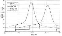
図1は、SAPO 34及び水から成る物質組を含む吸着器のための供給すべき離脱熱及び解放される吸着熱の特性線図であり、吸着器は吸着式冷凍機のサイクルにしたがって、ソーラーアシスト式の建物冷房のための作動条件で作動するようになっており、作動条件は、標準的に最大の吸着温度90℃、再冷温度及び最小の吸着温度35℃、蒸発温度15℃である。 FIG. 1 is a characteristic diagram of the heat of desorption to be supplied and the heat of adsorption released for an adsorber comprising a substance set consisting of SAPO 34 and water. It is designed to operate under the operating conditions for assisted building cooling. The operating conditions are typically a maximum adsorption temperature of 90 ° C, a recooling temperature and a minimum adsorption temperature of 35 ° C, and an evaporation temperature of 15 ° C. .
物質組の吸着平衡に基づき算出された特性線は、離脱のために吸着器にどれだけの熱量を供給して吸着器から吸着によってどれだけ多くの熱を取り出すかを示している。熱媒と吸着器との間の作動温度差はここではまだ考慮されていない。温度差を考慮すると、吸着特性線のピークと離脱特性線のピークとはさらに離れることになり、それというのは、離脱により熱媒は熱せられ、吸着剤は吸着により冷却されるからである。両方の特性線の交点は、離脱過程と吸着過程との間で回収される最大の熱量を表している。該熱量は、顕熱部分と収着熱部分とから成っている。該熱量のできるだけ多くの部分は、COPを最大にするために、吸着特性線の下側で(別の吸着器若しくはサイクルの後の段階での同じ吸着器の)離脱作動のために用いられるようにししてある。 The characteristic line calculated based on the adsorption equilibrium of the substance group indicates how much heat is supplied to the adsorber for desorption and how much heat is extracted from the adsorber by adsorption. The operating temperature difference between the heating medium and the adsorber has not yet been taken into account here. Considering the temperature difference, the peak of the adsorption characteristic line and the peak of the desorption characteristic line are further away from each other because the heat medium is heated by desorption and the adsorbent is cooled by adsorption. The intersection of both characteristic lines represents the maximum amount of heat recovered between the desorption process and the adsorption process. The amount of heat consists of a sensible heat portion and a sorption heat portion. As much of the heat as possible will be used for the desorption operation (of another adsorber or the same adsorber at a later stage in the cycle) below the adsorption characteristic line to maximize COP. It is.
図2に示す流体回路において、層状蓄熱器2は常に回路内にあり、ミクサV16及びV27は、利用可能なエネルギーのみが体積流量に基づき蓄熱器2から取り出され若しくは蓄熱器に供給されるように制御され、離脱のための残りのエネルギーは再熱器4から取り出し、若しくは吸着の際の余剰のエネルギーは再冷システムを介して取り出される。これによって、吸着器の吸着熱特性線を図1のように推移させることができ、この場合にあらゆる温度において再利用可能な熱量(特性線の交点に相当する)は蓄熱器2から取り出され、かつ(吸着特性線と離脱特性線との間の)付加的に必要な熱は再熱器4から取り出される。
In the fluid circuit shown in FIG. 2, the layered regenerator 2 is always in the circuit, and the mixers V16 and V27 are such that only the available energy is extracted from the regenerator 2 or supplied to the regenerator based on the volumetric flow rate. The remaining energy for control is taken out from the
しかしながら、前記回路における吸着器を運転するためのコストは高い。それというのは層状蓄熱器2及び再熱器4からの容積流がちょうど必要な熱比率に基づき各温度のために調節されねばならないからである。本発明では、簡単な流体回路を用いてほぼ理想的な熱回収を可能にするものである。
However, the cost for operating the adsorber in the circuit is high. This is because the volumetric flow from the stratified regenerator 2 and
再熱器4のために化学的な熱源を用いる場合(例えば、ガスバーナー)には、化学的な熱源からできるだけ低い温度レベルの熱を取り出すというような熱力学的な利点は得られない。この場合には層状蓄熱器の数値解析により明らかであるように、有利にはまず吸着器における離脱は層状蓄熱器2からの熱で行われ、最上段の蓄熱器層がもはや離脱のために十分でなくなった場合にようやく、再熱器4が接続される。この時点からは、蓄熱器を流体の回路から完全に切り離すか、若しくは吸着器3を再熱器4に短時間接続し、若しくは蓄熱器2が再熱器4及び吸着器3を含む回路で最上段の蓄熱器層のみを流体によって貫流されるようになっている(いずれの場合にも直ちに吸着循環流は最大の蓄熱器温度に達する)。
When a chemical heat source is used for the reheater 4 (for example, a gas burner), the thermodynamic advantage of taking heat at the lowest possible temperature level from the chemical heat source is not obtained. In this case, as is apparent from the numerical analysis of the layered regenerator, it is preferable that the desorption in the adsorber is first performed with heat from the layered regenerator 2 and the uppermost regenerator layer is no longer sufficient for desorption. The
別の例は、再熱器の熱源としてソーラーシステムを用いる場合であり(ソーラーシステムの効率は集熱パネル温度の上昇に伴って低下する)、若しくは熱源が蓄熱器である場合である。これによって装置全体にとって再熱器4をできるだけ低い温度で運転できるので有利である。層状蓄熱器の数値解析により明らかであるように、再熱の熱力学的な平均温度は、前述の例に比べて、つまり再熱器4を、最上段の蓄熱器層の所定の温度が達成される前にすでに接続した場合よりも低くなっている。再熱器4の接続は、蓄熱器内の温度に依存して制御される。蓄熱器から取り出される流体の温度は、わずかに多い量の取り出しでは急速に上昇して現在必要な離脱温度を超えており、取り出し量はわずかに減少し、再熱器4は接続される。これによって蓄熱器内の高い温度の層は、該層の温度レベルを吸着器3が離脱のために必要とするまで蓄熱されたままであり、同時に再熱における平均的な温度レベル(熱力学的、つまりエントロピーに基づく値)は低下される。
Another example is when a solar system is used as the heat source for the reheater (the efficiency of the solar system decreases with increasing heat collection panel temperature) or when the heat source is a regenerator . This has the advantage that the
本発明に基づくヒートポンプシステムの利点は、該ヒートポンプシステムが変化するサイクル条件下での運転に著しく適していることにあり、例えばヒートポンプを使用する場合に幾つかのサイクルにとって高い蒸発温度を必要とする(蒸発器と凝縮器との間の必要な温度レベルは低下される)場合には、両方の特性線の交点は上昇させられ、システムは自動的に高いCOPに達するようになっている。 The advantage of the heat pump system according to the invention is that it is highly suitable for operation under changing cycle conditions, for example requiring a high evaporation temperature for some cycles when using a heat pump. In the case where the required temperature level between the evaporator and the condenser is reduced, the intersection of both characteristic lines is raised and the system automatically reaches a high COP.
最適な熱回収の実現のために必要な蓄熱器寸法は、熱特性線の推移(図1)に依存している。一般的に、後の方で述べた一定温度での再熱にとっては、最大温度での(化石燃料形の)再熱の場合よりも大きな蓄熱器容積を必要としている。ソーラーシステムと接続する場合には、層状蓄熱器2はソーラーシステムの太陽緩衝蓄熱器内に組み込まれる(太陽緩衝蓄熱器は適切な充填及び放出装置2a,2bを備えている)。ソーラーシステムと組み合わせる例は、本発明に基づくシステムの有利な実施例をなすものであり、それというのは1つのアキュムレータシステムしか必要とせず、該アキュムレータシステムはソーラーシステムとしてもヒートポンプ若しくは冷凍機としても用いられるからである。 The size of the regenerator necessary for realizing optimal heat recovery depends on the transition of the thermal characteristic line (FIG. 1). In general, the reheating at a constant temperature described later requires a larger regenerator volume than the reheating at the maximum temperature (fossil fuel type). When connected to a solar system, the layered regenerator 2 is incorporated into the solar buffer solar storage of the solar system (the solar buffer regenerator is equipped with suitable filling and discharging devices 2a, 2b). The combination with a solar system is an advantageous embodiment of the system according to the invention, which requires only one accumulator system, which can be a solar system or a heat pump or refrigerator. It is because it is used.
本発明に基づくシステムの有利な実施例では、再熱の熱源は、吸着式蓄熱器であり、有利にはゼオライトアキュムレータ、殊にLTA-タイプのゼオライトを備えたゼオライトアキュムレータである。ゼオライトアキュムレータは有利にはモジュール式に形成されていて、次のように作動され、すなわちモジュールは順次に吸着作用を生ぜしめるのではなく、常に種々の吸着状態にある、つまり種々の温度レベル(互いに異なる温度レベル)の熱を供給できる複数のモジュールを並列に用いるようになっている。層状蓄熱器2のための再熱器4の熱源としては、ゼオライトアキュムレータの、吸着温度のまだ十分に高いモジュールが常に用いられる。このようなシステムは、太陽熱収集器による蓄熱にとって適していて、例えば100〜250℃の熱利を利用する装置のために開発されている。太陽収集器を用いて、安価なゼオライト(例えば、A4)から成るゼオライトアキュムレータの直接太陽熱式の離脱作動が可能である。ゼオライトアキュムレータの効果的なアキュムレータ密度は、本発明に基づくヒートポンプの運転によって高められ、それというのは蓄えられた熱は直接に建造物暖房のために用いられるのではなく、COPの最適なヒートポンプの運転のために用いられるからである。これによって、市販の安価なゼオライトを用いて、250kWh/m3の有効なエネルギー密度の蓄熱器を可能にしている。
In an advantageous embodiment of the system according to the invention, the heat source for reheating is an adsorption heat accumulator, preferably a zeolite accumulator, in particular a zeolite accumulator with an LTA-type zeolite. The zeolite accumulator is preferably modular and is operated in the following way, i.e. the modules do not produce an adsorption action in sequence, but are always in different adsorption states, i.e. different temperature levels (relative to each other). A plurality of modules capable of supplying heat at different temperature levels are used in parallel. As a heat source for the
太陽熱エネルギー利用のための装置に関連して、本発明に基づくヒートポンプシステムは、さらなる利点を有し、相乗効果の利用を可能にしている。例えばソーラーアシスト式のビル用冷房の場合には、冷凍機のCOPは昼と夜との温度差の利用によって高められる。このために冷凍機は、例えば相転換材料を含むシステム内に組み込まれ、相転換材料の溶融点は大気温度(標準的な気候において例えば26℃)をわずかに超えている。蓄熱器は夜間にヒートポンプの再冷器を介して熱を外部へ放出し、この場合に冷媒の循環のためのポンプエネルギーのみが供給される。日中に、蓄えられた冷却媒体は冷凍機の所定の段階で凝縮温度を低下させるために用いられる、このことは単数若しくは複数の吸着器3の離脱段階の終端で行われ、それというのは凝縮温度の低下によって低い温度での引き続く離脱が可能であり、その結果、層状蓄熱器2内の最後の吸着サイクルにまだ存在する多くの熱は離脱のために用いられ、これによって再熱器4はわずかな熱量だけを発生させ、及び/又は再熱用の熱は低い温度(つまり高い効率)で供給される。このようにして本発明に基づくヒートポンプシステムは、冷温蓄熱器の作用から冷凍機の高いCOP若しくはシステム全体の高い効率を達成している。
In connection with the device for solar energy utilization, the heat pump system according to the invention has further advantages and allows the use of synergistic effects. For example, in the case of solar-assisted building cooling, the COP of the refrigerator is increased by utilizing the temperature difference between day and night. For this purpose, the refrigerator is incorporated, for example, in a system comprising phase change material, the melting point of the phase change material being slightly above ambient temperature (eg 26 ° C. in a standard climate). The heat accumulator releases heat to the outside via the recooler of the heat pump at night, and in this case, only pump energy for circulating the refrigerant is supplied. During the day, the stored cooling medium is used to lower the condensation temperature at a given stage of the refrigerator, which is done at the end of the separation stage of the adsorber or adsorbers 3, because Subsequent desorption at lower temperatures is possible by lowering the condensation temperature, so that much of the heat still present in the last adsorption cycle in the stratified regenerator 2 is used for desorption, thereby causing the
吸着剤として親水性のゼオライト(例えばゼオライトA,X,Y)を用いる場合には、高い離脱温度(標準的には150℃)を必要とする。20−30Kからの温度上昇を、実際の使用(例えば、天井クーラーを備えたソーラー式冷房若しくは低温パネルヒーター及び地熱交換器を備えた暖房)にとって必要とする場合には、極めて平らに延びる吸着熱特性線と離脱温度特性線との間の交点は著しく高くなっている。このことは、吸着熱の大部分が層状蓄熱器2内に一時的に蓄えられて、次いで離脱のために用いられ、その結果高いCOPが達成されることを意味している。本発明に基づくシステムを用いることによって原理的には、複数段式の吸着ヒートポンプによってしか得られなかったCOP値を達成することができる。このことは、殊に層状蓄熱器2内の温度層の特性及び層状蓄熱器2の充放電量の制御の精度に依存している。このために次に述べる手段を層状蓄熱器に講じるようになっている。 When a hydrophilic zeolite (eg, zeolite A, X, Y) is used as the adsorbent, a high desorption temperature (typically 150 ° C.) is required. If the temperature rise from 20-30K is required for practical use (eg solar cooling with a ceiling cooler or heating with a cold panel heater and a geothermal exchanger), the heat of adsorption extending very flat The intersection between the characteristic line and the separation temperature characteristic line is significantly higher. This means that most of the heat of adsorption is temporarily stored in the stratified regenerator 2 and then used for disengagement, so that a high COP is achieved. By using the system according to the invention, it is possible in principle to achieve COP values that can only be obtained with a multistage adsorption heat pump. This depends in particular on the characteristics of the temperature layer in the layered regenerator 2 and the accuracy of control of the charge / discharge amount of the layered regenerator 2. For this purpose, the following measures are taken in the layered regenerator.
太陽熱システムの場合に、ヒートポンプの運転にとって層状蓄熱器2内における出力の比較的高い容積流しか必要とせず、それというのは、吸着器における熱拡散は標準的な使用例では太陽熱収集器におけるよりも著しく小さいからである。高い容積流はすべての層状蓄熱器にとって不都合であり、それというのは高い流速は蓄熱器内で容易に渦流及び乱流若しくは混合を生ぜしめて、温度層を崩壊させてしまうことになるからである。ソーラー技術で知られる層状蓄熱器、例えばSolvis社製のダイヤフラムフラップ付の蓄熱器(DE 3905874 C2)は、本発明に基づく実施例にとっては適していない。本発明に基づくシステムの層状蓄熱器2は、蓄熱器の垂直方向の混合を防止する装置を備えていると有利である。垂直方向の混合の防止は、例えば蓄熱器内に狭い間隔で水平に配置された複数の穴付薄板によって達成される。有利には、蓄熱器の入口側成層管の流体入口部分及び出口側成層管の流体出口部分の近傍に、流れ減衰用の構造体、例えば発泡性若しくはスポンジ状若しくは繊維製の構造体を組み込んである。前記穴付薄板は、流体入口部分及び流体出口部分の領域では中実に形成されていて、そこで垂直方向の混合を発生させないようになっている。有利にはそれぞれ2つの穴付薄板間で流体入口部分及び流体出口部分の周りに環状の減衰構造体(減衰リング)を設けてあり、減衰構造体は局所的な流速を減少させて、流れを減衰リングの周りにわたって均一にしている。循環流の層流形成は、原理的には受動的に、例えばEP 1076219 B1号明細書並びに、Roland Sailer 氏の論文「Schichtenspeichertechnologie fuer solare Warmwasserbereitung und Heizungsunterstuetzung(Heizungsjournal Juni 2000、26乃至28頁)」により公知の装置を用いて行われる。 In the case of a solar thermal system, heat pump operation requires only a relatively high volume flow of power in the stratified regenerator 2 because heat diffusion in the adsorber is more than that in a solar collector in standard use cases. This is because it is extremely small. High volume flow is inconvenient for all stratified regenerators because high flow rates can easily cause vortex and turbulence or mixing within the regenerator, causing the temperature layer to collapse. . Layered regenerators known from solar technology, for example the heat accumulator with diaphragm flap (DE 3905874 C2) from Solvis, are not suitable for the embodiments according to the invention. Advantageously, the stratified regenerator 2 of the system according to the invention is equipped with a device that prevents vertical mixing of the regenerator. Prevention of vertical mixing is achieved, for example, by a plurality of perforated sheets arranged horizontally at narrow intervals in the regenerator. Advantageously, a flow damping structure, such as a foam, sponge or fiber structure, is incorporated in the vicinity of the fluid inlet portion of the inlet side stratified tube of the regenerator and the fluid outlet portion of the outlet side stratified tube. is there. The perforated lamella is formed solid in the region of the fluid inlet portion and the fluid outlet portion so as not to cause vertical mixing there. An annular damping structure (attenuation ring) is preferably provided between the two perforated lamellas around the fluid inlet part and the fluid outlet part, the damping structure reducing the local flow velocity and reducing the flow. Evenly around the damping ring. Laminar flow formation in circulation is known in principle passively, for example from EP 1076219 B1 and Roland Sailer's paper “Schichtenspeichertechnologie fuer solare Warmwasserbereitung und Heizungsunterstuetzung (Heizungsjournal Juni 2000, pp. 26-28)”. It is performed using the apparatus of.
蓄熱器の問題若しくは混合を解決するために、有利には吸着器流過時の温度拡散を大きくして、容積流を相応に小さくするようになっている。この場合に効果的には、吸着器はサーマルウエブ(thermal wave)の場合と同様に形成されている(US 4694659号明細書の記載、参照)。サーマルウエブの場合の吸着器の運転と大きく異なる点は、本発明に基づくシステムのサーマルウエブの波長が流過される吸着剤ベッドよりも長くなっているのに対して、US 4694659号明細書の記載の技術に基づく波長は吸着剤ベッドよりも短くなっている。本発明に基づくシステムにおいて、吸着器3からの循環流温度は吸着過程の終端の直前で最大の吸着温度の近傍にとどまっておらず、著しき低下している。したがって、Shelton氏によるサーマルウエブシステム(US 4694659号明細書)の場合と異なり、本発明に基づくシステムは層状蓄熱器2に基づきCOPに不都合な影響を及ぼさないようになっている。吸着器3を、熱移送流体のための長くされた流路を備えた熱交換器として形成することにより、吸着器内での熱伝導による内部の大きな不可逆なしに入口と出口との間の大きな温度拡散で吸着器の運転を可能にし、その結果改善された蓄熱器成層を得るという目的は達成されている。 In order to solve the problem or mixing of the regenerator, the temperature diffusion during the adsorber flow is advantageously increased so that the volume flow is correspondingly reduced. Effectively in this case, the adsorber is formed in the same way as in the case of a thermal wave (see US Pat. No. 4,694,659). The major difference from the operation of the adsorber in the case of the thermal web is that the wavelength of the thermal web of the system according to the present invention is longer than that of the adsorbent bed to be passed, whereas in US 4694659 The wavelength based on the described technique is shorter than the adsorbent bed. In the system according to the present invention, the circulating flow temperature from the adsorber 3 does not remain in the vicinity of the maximum adsorption temperature just before the end of the adsorption process, but is significantly reduced. Therefore, unlike the case of the thermal web system by Shelton (US Pat. No. 4,694,659), the system according to the invention is based on the stratified regenerator 2 so as not to adversely affect the COP. By forming the adsorber 3 as a heat exchanger with an elongated flow path for the heat transfer fluid, there is a large gap between the inlet and outlet without significant internal irreversibility due to heat conduction in the adsorber. The object of enabling the operation of the adsorber with temperature diffusion and consequently obtaining an improved regenerator stratification has been achieved.
100℃よりも高い離脱温度を必要とする吸着剤を用いる場合には、層状蓄熱器2は蓄圧器として形成されると有利であり、水が熱媒の主構成要素として用いられる。100℃〜250℃の中間の温度領域のための太陽熱システムの場合にも、集熱回路のためのサーモオイルの代わりに圧縮水を用いる傾向にある(例えば、W.Weiss 及びM.Rommel 氏の論文「Medium Temperature Collectors, IEA-SHC Task 33 report,Mai 2005,」[http://energytech.at/pdf/medium temperature collectors task33.pdf]、参照)。この種の集熱システムの熱流量は、付加的な熱交換器を必要とすることなしに直接にヒートポンプの層状蓄熱器2内に供給される。多くの場合に太陽熱収集システムから蓄熱器2内への層流供給は、公知技術に属する層流供給ランス2aを介して行われ(受動的に、つまり蓄熱器2内の流体の密度さに基づき制御される)。集熱器による容積流の調整によって、集熱器からの流体の温度(及び層形成度)は制御され、容積流を蓄熱器2の離脱に必要な層表面に近づけて、非太陽熱の再熱エネルギーの需要量を最小にするようになっている。 When using an adsorbent that requires a desorption temperature higher than 100 ° C., the layered regenerator 2 is advantageously formed as a pressure accumulator, and water is used as the main component of the heat transfer medium. Solar thermal systems for intermediate temperature ranges from 100 ° C to 250 ° C also tend to use compressed water instead of thermo-oil for heat collection circuits (eg, by W. Weiss and M. Rommel (See the paper "Medium Temperature Collectors, IEA-SHC Task 33 report, Mai 2005," [http://energytech.at/pdf/medium temperature collectors task33.pdf]). The heat flow of this type of heat collection system is fed directly into the heat pump layered regenerator 2 without the need for an additional heat exchanger. In many cases, the laminar flow supply from the solar heat collection system into the regenerator 2 is performed via a laminar flow supply lance 2a belonging to the known art (passively, that is, based on the density of the fluid in the regenerator 2). Controlled). By adjusting the volume flow by the heat collector, the temperature of the fluid from the heat collector (and the degree of layer formation) is controlled, and the volume flow is brought closer to the surface of the layer necessary for the detachment of the heat accumulator 2 to reheat non-solar heat. Energy demand is minimized.
本発明に基づく有利な実施例では、再熱器4は層状蓄熱器2の上方の領域に組み込まれており、このことは従来のソーラーシステムを含む装置(例えば、EP 0841522A2号明細書)により知られている。
In an advantageous embodiment according to the invention, the
1 流体回路、 2 層状蓄熱器、 2a 充填ランス、 2b 放出ランス、 3 吸着器、 3a 凝縮器、 3b 蒸発器、 4 再熱器、 5 ポンプ、 6,7 ミクサ 1 fluid circuit, 2 layered heat accumulator, 2a filling lance, 2b discharge lance, 3 adsorber, 3a condenser, 3b evaporator, 4 reheater, 5 pump, 6, 7 mixer
Claims (16)
吸着剤を有する吸着器(3)と、An adsorber (3) having an adsorbent;
層状蓄熱器(2)と、A layered regenerator (2),
吸着サイクルにおいて前記吸着器から放出される吸着熱のうち、最大に吸着された吸着器の離脱に必要な温度よりも低い温度で生じた吸着熱を、熱移送媒体を介して放出するように構成されたヒートシンクと、Of the heat of adsorption released from the adsorber in the adsorption cycle, the heat of adsorption generated at a temperature lower than the temperature necessary for detachment of the adsorber maximally adsorbed is released through the heat transfer medium. Heat sink
熱源と、A heat source,
を備え、With
前記層状蓄熱器(2)は、互いに異なる高さに互いに異なる温度の温度層を形成する液状の熱媒で充填されている容器と、所定の高さの温度層に熱媒を供給し、かつ所定の高さの温度層から熱媒を取り出すための装置と、を有し、The layered regenerator (2) supplies a heat medium to a container filled with a liquid heat medium that forms temperature layers having different temperatures at different heights, and a temperature layer having a predetermined height, and An apparatus for taking out the heat medium from the temperature layer of a predetermined height,
前記層状蓄熱器(2)は、吸着サイクルにおいて前記吸着器から放出され熱移送媒体を介して与えられる吸着熱を、吸着時の前記吸着器(3)における吸着量によって決まる発熱温度と対応する、前記層状蓄熱器の所定の高さの温度層に供給し、かつ、離脱サイクルにおいて、離脱時の前記吸着器(3)における吸着量によって決まる離脱に要する温度と対応する、該層状蓄熱器の所定の高さの温度層から、前記熱移送媒体を介して前記吸着器に供給し、The layered heat accumulator (2) corresponds to an exothermic temperature determined by the amount of adsorption in the adsorber (3) during adsorption, with respect to the adsorption heat released from the adsorber and given through the heat transfer medium in an adsorption cycle. A predetermined temperature of the layered regenerator that is supplied to a temperature layer of a predetermined height of the layered regenerator and that corresponds to a temperature required for desorption determined by the amount of adsorption in the adsorber (3) at the time of desorption in a desorption cycle; From the temperature layer of the height, to the adsorber through the heat transfer medium,
前記熱源は、前記吸着器における離脱のために必要な温度の熱媒を前記蓄熱器から取り出すことができない場合に、先行の吸着サイクルによって前記蓄熱器内に蓄えられている温度よりも高い温度の熱媒を形成するか、又は、前記蓄熱器内で必要な温度で蓄えられているものの離脱には十分な熱量ではない場合に、残りの熱量を形成することを特徴とする、吸着式ヒートポンプシステム。The heat source has a temperature higher than that stored in the heat accumulator by a preceding adsorption cycle when a heat medium having a temperature required for separation in the adsorber cannot be taken out of the heat accumulator. An adsorption heat pump system that forms a heat medium or forms a remaining amount of heat when it is stored at a necessary temperature in the regenerator but is not sufficient for detachment. .
Applications Claiming Priority (3)
| Application Number | Priority Date | Filing Date | Title |
|---|---|---|---|
| DE102006043715A DE102006043715A1 (en) | 2006-09-18 | 2006-09-18 | Adsorption heat pump with heat storage |
| DE102006043715.2 | 2006-09-18 | ||
| PCT/EP2007/008021 WO2008034561A2 (en) | 2006-09-18 | 2007-09-14 | Adsorption heat pump with heat accumulator |
Publications (3)
| Publication Number | Publication Date |
|---|---|
| JP2010503823A JP2010503823A (en) | 2010-02-04 |
| JP2010503823A5 JP2010503823A5 (en) | 2012-09-27 |
| JP5904697B2 true JP5904697B2 (en) | 2016-04-20 |
Family
ID=39104867
Family Applications (1)
| Application Number | Title | Priority Date | Filing Date |
|---|---|---|---|
| JP2009528628A Active JP5904697B2 (en) | 2006-09-18 | 2007-09-14 | Adsorption heat pump |
Country Status (5)
| Country | Link |
|---|---|
| US (1) | US8631667B2 (en) |
| EP (1) | EP2076721B1 (en) |
| JP (1) | JP5904697B2 (en) |
| DE (1) | DE102006043715A1 (en) |
| WO (1) | WO2008034561A2 (en) |
Families Citing this family (19)
| Publication number | Priority date | Publication date | Assignee | Title |
|---|---|---|---|---|
| DE102008053554A1 (en) * | 2008-10-28 | 2010-04-29 | Behr Gmbh & Co. Kg | Air conditioning system for a building |
| JP2012513008A (en) * | 2008-12-19 | 2012-06-07 | インベンソール ゲーエムベーハー | Depressurization element for diverting recooling volume flow in sorption machines (Sorption Machines) |
| WO2011054347A1 (en) * | 2009-11-04 | 2011-05-12 | Invensor Gmbh | Refrigerating machine having freezing-protected re-cooling systems |
| DE102011011308A1 (en) * | 2011-02-15 | 2012-08-16 | Zeo-Tech Zeolith-Technologie Gmbh | Solar operated sorption apparatus |
| US20120234033A1 (en) * | 2011-03-17 | 2012-09-20 | Solarpath, Inc. | Solar window and solar wall for cooling an environment |
| DE102011102036B4 (en) | 2011-05-19 | 2013-05-29 | Sortech Ag | Method for operating a cyclically operating thermal adsorption heat plant and apparatus |
| CN102679616B (en) * | 2012-02-17 | 2014-07-16 | 南京工业大学 | Double-stage adsorption refrigerating recycling system |
| JP6083123B2 (en) * | 2012-03-30 | 2017-02-22 | 富士通株式会社 | Adsorption heat pump system and drive method of adsorption heat pump |
| DE102013013835B4 (en) * | 2012-08-22 | 2017-05-18 | Kabushiki Kaisha Toyota Chuo Kenkyusho | Adsorption heat pump system and method for generating cooling power |
| DE102013021285A1 (en) | 2013-12-19 | 2015-06-25 | Stiebel Eltron Gmbh & Co. Kg | Domestic appliance and heat storage unit |
| DE102014113450A1 (en) | 2014-09-18 | 2016-03-24 | Karlsruher Institut für Technologie | Adsorptive heat transformation arrangement |
| EP3252398A1 (en) * | 2016-05-30 | 2017-12-06 | Climatewell AB (publ) | Hybrid heat pipe |
| DE102016215387A1 (en) | 2016-08-17 | 2018-02-22 | Mahle International Gmbh | Container for forming a heat buffer |
| DE102016215374A1 (en) | 2016-08-17 | 2018-02-22 | Mahle International Gmbh | Arrangement, in particular chiller or heat pump |
| DE102016215381A1 (en) | 2016-08-17 | 2018-02-22 | Mahle International Gmbh | Arrangement, in particular chiller or heat pump |
| DE102016215368A1 (en) | 2016-08-17 | 2018-02-22 | Mahle International Gmbh | Arrangement, in particular chiller or heat pump |
| DE102018206141A1 (en) | 2018-04-20 | 2019-10-24 | Mahle International Gmbh | Container for forming a heat buffer |
| DE102018109575A1 (en) | 2018-04-20 | 2019-10-24 | Karlsruher Institut für Technologie | Adsorption heat pump or chiller and procedures for their operation |
| DE102018109577B3 (en) | 2018-04-20 | 2019-05-09 | Karlsruher Institut für Technologie | Hybrid heat pump with compression and adsorption cycle, as well as procedures for operation and use |
Family Cites Families (32)
| Publication number | Priority date | Publication date | Assignee | Title |
|---|---|---|---|---|
| US2486833A (en) * | 1944-11-17 | 1949-11-01 | Walter J Kelly | Heat storage and supply means |
| US4034569A (en) * | 1974-11-04 | 1977-07-12 | Tchernev Dimiter I | Sorption system for low-grade (solar) heat utilization |
| US4070870A (en) * | 1976-10-04 | 1978-01-31 | Borg-Warner Corporation | Heat pump assisted solar powered absorption system |
| AU500467B2 (en) * | 1977-04-15 | 1979-05-24 | Matsushita Electric Industrial Co., Ltd. | Solar heating & cooling system |
| JPS57104305A (en) | 1980-12-19 | 1982-06-29 | Fujitsu Ltd | Carrier extracting system |
| JPS5972451U (en) * | 1982-07-09 | 1984-05-17 | 高砂熱学工業株式会社 | Stratified heat storage tank |
| JPS5972451A (en) | 1982-10-18 | 1984-04-24 | Konishiroku Photo Ind Co Ltd | Magnetic toner |
| FR2538884B1 (en) * | 1983-01-03 | 1986-02-21 | Jeumont Schneider | SOLAR ENERGY REFRIGERATOR |
| JPS6166088A (en) | 1984-09-06 | 1986-04-04 | Fujita Corp | Temperature stratification type heat storage tank |
| US4694659A (en) | 1985-05-03 | 1987-09-22 | Shelton Samuel V | Dual bed heat pump |
| DE3905874A1 (en) | 1989-02-23 | 1990-08-30 | Solvis Energiesysteme Gmbh | HOT WATER TANK WITH A HEATING CIRCUIT FLOWED FROM WATER WATER WITH OUTDOOR HEATING ELEMENT AND WITH A CHANGING LOADING DEVICE |
| DE4302281A1 (en) | 1993-01-25 | 1994-07-28 | Auf Adlershofer Umweltschutzte | Thermal energy absorbing and releasing device |
| JPH06257884A (en) | 1993-03-09 | 1994-09-16 | Toshiba Corp | Heat utilization apparatus |
| DE4333829A1 (en) | 1993-09-30 | 1995-04-06 | Auf Adlershofer Umweltschutzte | Method and system for storing thermal energy (heat energy) |
| GB9419202D0 (en) | 1994-09-23 | 1994-11-09 | Univ Warwick | Thermal compressive device |
| JPH08178466A (en) | 1994-12-22 | 1996-07-12 | Sanyo Electric Co Ltd | Heat exchanger utilizing metallic hydride |
| JP3302859B2 (en) | 1995-04-28 | 2002-07-15 | 沖縄電力株式会社 | Method for forming refrigeration cycle of solar thermal adsorption regenerative refrigeration system |
| JP2856246B2 (en) | 1996-10-16 | 1999-02-10 | 株式会社フジクラ | Heat recovery / supply device |
| EP0841522A3 (en) | 1996-11-11 | 2000-01-12 | SOLVIS Solarsysteme GmbH | Accumulator with insertable heat generator |
| JP3842413B2 (en) | 1997-11-26 | 2006-11-08 | 株式会社日本製鋼所 | Sensible heat recovery device and heat storage tank |
| DE19824315B4 (en) | 1997-12-11 | 2005-10-06 | Fraunhofer-Gesellschaft zur Förderung der angewandten Forschung e.V. | Heat pump compact device with integrated primary energy heat source for controlled ventilation and heat energy supply of low-energy buildings or passive houses |
| JPH11223415A (en) | 1998-02-05 | 1999-08-17 | Denso Corp | Refrigerating device |
| JP2950474B1 (en) | 1998-03-27 | 1999-09-20 | 三洋電機株式会社 | Solar powered refrigerator |
| JP3514110B2 (en) * | 1998-05-01 | 2004-03-31 | トヨタ自動車株式会社 | Operation control method of air conditioner system |
| DE19908666B4 (en) * | 1999-02-27 | 2007-12-06 | Ludwig, Jürgen, Dipl.-Ing. | Sorption heat pump / chiller with heating of the previous adsorber to desorption temperature by adsorption |
| DE19937985C1 (en) | 1999-08-11 | 2001-03-22 | Roland Sailer | Device for layering fluids in containers depending on their density |
| JP4175445B2 (en) | 1999-11-26 | 2008-11-05 | 西松建設株式会社 | Hot water supply system and structure including the hot water supply system |
| US6536677B2 (en) * | 2000-06-08 | 2003-03-25 | University Of Puerto Rico | Automation and control of solar air conditioning systems |
| JP4425444B2 (en) | 2000-09-05 | 2010-03-03 | 株式会社日本製鋼所 | Heat storage tank |
| DE10212688B4 (en) | 2002-03-21 | 2010-11-25 | Solvis Gmbh & Co.Kg | Hot water storage |
| CN100501299C (en) * | 2003-04-01 | 2009-06-17 | 三菱化学株式会社 | Adsorbent for adsorption heat pump, adsorbent for humidity-control air conditioner, adsorption heat pump and humidity-control air conditioner |
| DE102004052976A1 (en) | 2004-10-29 | 2006-05-04 | Sortech Ag | Process for the preparation of a substrate coated with a zeolite layer |
-
2006
- 2006-09-18 DE DE102006043715A patent/DE102006043715A1/en not_active Withdrawn
-
2007
- 2007-09-14 WO PCT/EP2007/008021 patent/WO2008034561A2/en active Application Filing
- 2007-09-14 EP EP07818164.1A patent/EP2076721B1/en not_active Not-in-force
- 2007-09-14 US US12/441,673 patent/US8631667B2/en not_active Expired - Fee Related
- 2007-09-14 JP JP2009528628A patent/JP5904697B2/en active Active
Also Published As
| Publication number | Publication date |
|---|---|
| WO2008034561A3 (en) | 2008-05-08 |
| US8631667B2 (en) | 2014-01-21 |
| JP2010503823A (en) | 2010-02-04 |
| US20090282846A1 (en) | 2009-11-19 |
| DE102006043715A1 (en) | 2008-03-27 |
| EP2076721B1 (en) | 2018-11-07 |
| EP2076721A2 (en) | 2009-07-08 |
| WO2008034561A2 (en) | 2008-03-27 |
Similar Documents
| Publication | Publication Date | Title |
|---|---|---|
| JP5904697B2 (en) | Adsorption heat pump | |
| Meunier | Theoretical performances of solid adsorbent cascading cycles using the zeolite-water and active carbon-methanol pairs: four case studies | |
| Alahmer et al. | Comprehensive strategies for performance improvement of adsorption air conditioning systems: A review | |
| US7578143B2 (en) | Thermal compressive device | |
| Saha et al. | Computational analysis of an advanced adsorption-refrigeration cycle | |
| Zhao et al. | Investigation of a 10 kWh sorption heat storage device for effective utilization of low-grade thermal energy | |
| CN100419345C (en) | Solid adsorptive refrigerator | |
| Casey et al. | Salt impregnated desiccant matrices for ‘open’thermochemical energy conversion and storage–Improving energy density utilisation through hygrodynamic & thermodynamic reactor design | |
| Vasiliev et al. | Solar-gas solid sorption refrigerator | |
| CN101793447B (en) | Cold-heat combined supply solar thermochemical adsorption composite energy storing device | |
| RU2142101C1 (en) | Modified heat-transfer apparatus and method for solid-to-steam sorption systems | |
| CN101458007B (en) | Solution energy-saving equipment based on film distillation technology and method thereof | |
| Jiang et al. | Investigation on an innovative cascading cycle for power and refrigeration cogeneration | |
| CN101818967B (en) | Composite energy storage and supply device via thermochemical temperature swing adsorption combined cold-heat supply | |
| CN101354202A (en) | Back heating type two-stage thermochemistry adsorption cooling cycle system based on voltage transformation desorption technique | |
| Vasiliev et al. | A solar and electrical solid sorption refrigerator | |
| Naseem et al. | Dynamic simulation and exergy analysis of adsorption chiller powered by low-grade waste heat from a fuel-cell system: Effect of multibed configuration and time constant | |
| US11788775B2 (en) | Heat distribution device | |
| CN204001877U (en) | A kind of communication base station | |
| Vasiliev | Sorption machines with a heat pipe thermal control | |
| WO2003071197A2 (en) | Energy efficient adsorption system | |
| Hirota et al. | Characteristics of a heat output of an adsorption heat pump aided with pumping | |
| Vasiliev | Solid sorption heat pumps in tri-generation | |
| Vasiliev | Solar sorption refrigerator | |
| Antukh et al. | Solid sorption cooler with composite sorbent bed and heat pipe thermal control |
Legal Events
| Date | Code | Title | Description |
|---|---|---|---|
| A621 | Written request for application examination |
Free format text: JAPANESE INTERMEDIATE CODE: A621 Effective date: 20100810 |
|
| RD04 | Notification of resignation of power of attorney |
Free format text: JAPANESE INTERMEDIATE CODE: A7424 Effective date: 20101228 |
|
| A131 | Notification of reasons for refusal |
Free format text: JAPANESE INTERMEDIATE CODE: A131 Effective date: 20120210 |
|
| A601 | Written request for extension of time |
Free format text: JAPANESE INTERMEDIATE CODE: A601 Effective date: 20120510 |
|
| A602 | Written permission of extension of time |
Free format text: JAPANESE INTERMEDIATE CODE: A602 Effective date: 20120517 |
|
| A601 | Written request for extension of time |
Free format text: JAPANESE INTERMEDIATE CODE: A601 Effective date: 20120611 |
|
| A602 | Written permission of extension of time |
Free format text: JAPANESE INTERMEDIATE CODE: A602 Effective date: 20120618 |
|
| A601 | Written request for extension of time |
Free format text: JAPANESE INTERMEDIATE CODE: A601 Effective date: 20120710 |
|
| A602 | Written permission of extension of time |
Free format text: JAPANESE INTERMEDIATE CODE: A602 Effective date: 20120718 |
|
| A524 | Written submission of copy of amendment under section 19 (pct) |
Free format text: JAPANESE INTERMEDIATE CODE: A524 Effective date: 20120809 |
|
| A02 | Decision of refusal |
Free format text: JAPANESE INTERMEDIATE CODE: A02 Effective date: 20130401 |
|
| A521 | Written amendment |
Free format text: JAPANESE INTERMEDIATE CODE: A523 Effective date: 20130801 |
|
| A911 | Transfer of reconsideration by examiner before appeal (zenchi) |
Free format text: JAPANESE INTERMEDIATE CODE: A911 Effective date: 20130808 |
|
| A912 | Removal of reconsideration by examiner before appeal (zenchi) |
Free format text: JAPANESE INTERMEDIATE CODE: A912 Effective date: 20131227 |
|
| A601 | Written request for extension of time |
Free format text: JAPANESE INTERMEDIATE CODE: A601 Effective date: 20140421 |
|
| A602 | Written permission of extension of time |
Free format text: JAPANESE INTERMEDIATE CODE: A602 Effective date: 20140424 |
|
| A601 | Written request for extension of time |
Free format text: JAPANESE INTERMEDIATE CODE: A601 Effective date: 20140520 |
|
| A602 | Written permission of extension of time |
Free format text: JAPANESE INTERMEDIATE CODE: A602 Effective date: 20140528 |
|
| A601 | Written request for extension of time |
Free format text: JAPANESE INTERMEDIATE CODE: A601 Effective date: 20140619 |
|
| A602 | Written permission of extension of time |
Free format text: JAPANESE INTERMEDIATE CODE: A602 Effective date: 20140625 |
|
| A601 | Written request for extension of time |
Free format text: JAPANESE INTERMEDIATE CODE: A601 Effective date: 20150113 |
|
| A601 | Written request for extension of time |
Free format text: JAPANESE INTERMEDIATE CODE: A601 Effective date: 20150212 |
|
| A601 | Written request for extension of time |
Free format text: JAPANESE INTERMEDIATE CODE: A601 Effective date: 20150312 |
|
| A521 | Written amendment |
Free format text: JAPANESE INTERMEDIATE CODE: A523 Effective date: 20150414 |
|
| RD13 | Notification of appointment of power of sub attorney |
Free format text: JAPANESE INTERMEDIATE CODE: A7433 Effective date: 20150528 |
|
| A521 | Written amendment |
Free format text: JAPANESE INTERMEDIATE CODE: A821 Effective date: 20150528 |
|
| A601 | Written request for extension of time |
Free format text: JAPANESE INTERMEDIATE CODE: A601 Effective date: 20150825 |
|
| A601 | Written request for extension of time |
Free format text: JAPANESE INTERMEDIATE CODE: A601 Effective date: 20150925 |
|
| A601 | Written request for extension of time |
Free format text: JAPANESE INTERMEDIATE CODE: A601 Effective date: 20151026 |
|
| A521 | Written amendment |
Free format text: JAPANESE INTERMEDIATE CODE: A523 Effective date: 20151125 |
|
| A61 | First payment of annual fees (during grant procedure) |
Free format text: JAPANESE INTERMEDIATE CODE: A61 Effective date: 20160315 |
|
| R150 | Certificate of patent or registration of utility model |
Ref document number: 5904697 Country of ref document: JP Free format text: JAPANESE INTERMEDIATE CODE: R150 |
|
| R250 | Receipt of annual fees |
Free format text: JAPANESE INTERMEDIATE CODE: R250 |
|
| R250 | Receipt of annual fees |
Free format text: JAPANESE INTERMEDIATE CODE: R250 |