JP5887687B2 - bicycle - Google Patents
bicycle Download PDFInfo
- Publication number
- JP5887687B2 JP5887687B2 JP2013544396A JP2013544396A JP5887687B2 JP 5887687 B2 JP5887687 B2 JP 5887687B2 JP 2013544396 A JP2013544396 A JP 2013544396A JP 2013544396 A JP2013544396 A JP 2013544396A JP 5887687 B2 JP5887687 B2 JP 5887687B2
- Authority
- JP
- Japan
- Prior art keywords
- stem
- front wheel
- handle
- steering
- wheel
- Prior art date
- Legal status (The legal status is an assumption and is not a legal conclusion. Google has not performed a legal analysis and makes no representation as to the accuracy of the status listed.)
- Expired - Fee Related
Links
Images


Classifications
-
- B—PERFORMING OPERATIONS; TRANSPORTING
- B62—LAND VEHICLES FOR TRAVELLING OTHERWISE THAN ON RAILS
- B62K—CYCLES; CYCLE FRAMES; CYCLE STEERING DEVICES; RIDER-OPERATED TERMINAL CONTROLS SPECIALLY ADAPTED FOR CYCLES; CYCLE AXLE SUSPENSIONS; CYCLE SIDE-CARS, FORECARS, OR THE LIKE
- B62K21/00—Steering devices
-
- B—PERFORMING OPERATIONS; TRANSPORTING
- B62—LAND VEHICLES FOR TRAVELLING OTHERWISE THAN ON RAILS
- B62K—CYCLES; CYCLE FRAMES; CYCLE STEERING DEVICES; RIDER-OPERATED TERMINAL CONTROLS SPECIALLY ADAPTED FOR CYCLES; CYCLE AXLE SUSPENSIONS; CYCLE SIDE-CARS, FORECARS, OR THE LIKE
- B62K15/00—Collapsible or foldable cycles
- B62K15/006—Collapsible or foldable cycles the frame being foldable
- B62K15/008—Collapsible or foldable cycles the frame being foldable foldable about 2 or more axes
-
- B—PERFORMING OPERATIONS; TRANSPORTING
- B62—LAND VEHICLES FOR TRAVELLING OTHERWISE THAN ON RAILS
- B62K—CYCLES; CYCLE FRAMES; CYCLE STEERING DEVICES; RIDER-OPERATED TERMINAL CONTROLS SPECIALLY ADAPTED FOR CYCLES; CYCLE AXLE SUSPENSIONS; CYCLE SIDE-CARS, FORECARS, OR THE LIKE
- B62K3/00—Bicycles
- B62K3/02—Frames
- B62K3/10—Frames of single-beam type, i.e. connecting steering head to rear axle
-
- B—PERFORMING OPERATIONS; TRANSPORTING
- B62—LAND VEHICLES FOR TRAVELLING OTHERWISE THAN ON RAILS
- B62K—CYCLES; CYCLE FRAMES; CYCLE STEERING DEVICES; RIDER-OPERATED TERMINAL CONTROLS SPECIALLY ADAPTED FOR CYCLES; CYCLE AXLE SUSPENSIONS; CYCLE SIDE-CARS, FORECARS, OR THE LIKE
- B62K15/00—Collapsible or foldable cycles
- B62K2015/003—Collapsible or foldable cycles having a foldable crank or pedal
Landscapes
- Engineering & Computer Science (AREA)
- Mechanical Engineering (AREA)
- Steering Devices For Bicycles And Motorcycles (AREA)
- Motorcycle And Bicycle Frame (AREA)
- Automatic Cycles, And Cycles In General (AREA)
- Handcart (AREA)
Description
本発明は、自転車に関するもので、特に、使用者が自転車を使用・運搬するにおいて少ない力で可能で、携帯性に優れた自転車に関する。 The present invention relates to a bicycle, and more particularly, to a bicycle that can be used with less force when a user uses and transports the bicycle and has excellent portability.
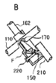
図1Aは、前輪のみを別途に操向することができる手段がないか不備で不安定であり、図1Bは、韓国公開特許第16444号(2001年3月5日)であって、前輪を操向しようと試みたときに、前記操向に対する力の支点となる手段が備えられておらず、本体全体をひねるか反動を利用するしかないため、優れた運転者(使用者)でなければ操向の操作が難解であり、図1Cは、韓国公開実用新案第19682号(1993年9月23日)であり、サドルを支点として操向ハンドルを操作して操向することはできるが、同時にペダル等の動力体系が前記操向ハンドルに従って共に左右回転するため、使用者の体が向かう方向とずれて前記ペダルに使用者の足を持続的に接触することが難しく、また有効な力を伝達することができない。 FIG. 1A shows that there is no means that can separately steer only the front wheels, and that it is unstable and unstable. FIG. 1B shows Korean Patent No. 16444 (March 5, 2001), When trying to steer, there is no means to serve as a fulcrum of force for the steering, and the only way to turn is to use the whole body or use reaction, so if you are not an excellent driver (user) The steering operation is difficult, and FIG. 1C is the Korean public utility model No. 19682 (September 23, 1993), which can be operated by operating the steering handle with the saddle as a fulcrum, At the same time, since the power system such as a pedal rotates left and right together according to the steering handle, it is difficult to continuously contact the foot of the user with the pedal deviating from the direction in which the user's body heads, and an effective force is provided. I can't communicate.
特に、操向の角度が大きいと、前記ペダルを踏むこと自体が不可能になる。 In particular, when the steering angle is large, it is impossible to step on the pedal itself.
本発明は、自転車の車体(フレーム)の構造を極小化して軽量化をなし、使用・運搬において少ない力ですみ、最小の大きさをなすことができるようにして携帯性を極大化させ、同時にペダルを踏む足の位置を楽にすることができるようにする。 The present invention minimizes the structure of the bicycle body (frame) to reduce weight, requires less force in use and transportation, maximizes portability by allowing the smallest size to be achieved, and at the same time Make it easier to position the foot of the pedal.
前輪ステム; 前記前輪ステムの上端に備えられるサドル; 前記前輪ステムの下端に備えられる前輪; 前記前輪を駆動する駆動部; 前記サドルと前記前輪ステムの間に備えられるハンドルステム及び、前記ハンドルステムの前端に備えられるハンドルから構成されるハンドル部;を含む前輪部と、後輪ステム; 前記後輪ステムの上端に前記前輪ステムを軸受けする操向軸受け; 前記後輪ステムの下端に備えられる後輪;を含む後輪部から構成され、前記ハンドルを操作すれば前記ハンドル部が左右に方向転換をするように構成される。 A front wheel stem; a saddle provided at an upper end of the front wheel stem; a front wheel provided at a lower end of the front wheel stem; a drive unit for driving the front wheel; a handle stem provided between the saddle and the front wheel stem; A front wheel portion including a handle portion including a handle provided at a front end; and a rear wheel stem; a steering bearing for bearing the front wheel stem at an upper end of the rear wheel stem; a rear wheel provided at a lower end of the rear wheel stem , And the steering wheel is configured to change its direction left and right when the steering wheel is operated.
また、前記ハンドルを操作すれば、前記操向軸受けを軸として前記前輪部が操向動作するように構成される。 Further, when the steering wheel is operated, the front wheel portion is configured to steer about the steering bearing.
あるいは、前記ハンドルステムは、前記前輪ステムに設置され、前記後輪ステムの操向軸受けは、前記ハンドルステムの後端を操向軸になるように軸受けすることができる。 Alternatively, the handle stem may be installed on the front wheel stem, and the steering bearing of the rear wheel stem may be supported so that the rear end of the handle stem becomes the steering shaft.
本発明によれば、既存の前輪駆動形態の自転車の場合、前輪が方向を転換すれば、クランクペダルと衝突を避けるためにクランクペダルも同一の方向に転換しなければならず、これによって運転者の脚の運動軌跡と角が生じてちゃんとした駆動力を伝達することができないところ、このような短所を解消する。 According to the present invention, in the case of an existing front wheel drive type bicycle, if the front wheel changes direction, the crank pedal must also change in the same direction in order to avoid collision with the crank pedal. This eliminates the shortcomings in that the leg's movement trajectory and angle are generated and the proper driving force cannot be transmitted.
また、方向転換をする方に使用者の体をひねったり傾けることができて方向転換の反対側に作用する遠心力をこらえることが容易で、方向転換と共に体をひねって傾きながらよりダイナミックなライディングの味を楽しむことができる。 In addition, it is easy to hold the centrifugal force acting on the opposite side of the direction change by twisting and tilting the user's body to the direction change, and more dynamic riding while twisting the body along with the direction change You can enjoy the taste of
本発明において、その範囲は例示された実施の他にも、本発明の技術的思想を含む他の実施のものも含む。 In the present invention, the scope includes other implementations including the technical idea of the present invention in addition to the illustrated implementations.
本発明は、ハンドル部; 前記ハンドル部の後端部に連結され、上端にサドルを備え下端に前輪を備える前輪ステム; 前記ハンドル部の後端部または前記前輪ステムに連結され、下端に後輪を備える後輪ステム;を含んで構成され、前記ハンドル部を動作させると前記後輪ステムの上端部を軸として前記前輪ステムが左右に操向回転(屈折含む)するように構成される。 The present invention relates to a handle portion; a front wheel stem connected to a rear end portion of the handle portion and having a saddle at an upper end and a front wheel at a lower end; connected to a rear end portion of the handle portion or the front wheel stem; The front wheel stem is configured to be steered to the left and right (including refraction) around the upper end of the rear wheel stem when the handle portion is operated.
前記操向回転は、前記ハンドル部のハンドルまたはハンドルステム自体を回すか曲げるか動かすかして操作すれば、この操作による動作が前記後輪ステム上端部の回転軸に対して前記前輪ステムが操向可能なように左・右に回転するように構成され、これを操向操作手段という。 If the steering rotation is operated by turning, bending or moving the handle of the handle portion or the handle stem itself, the operation by this operation is controlled by the front wheel stem with respect to the rotation axis of the upper end portion of the rear wheel stem. It is configured to rotate left and right so that it can be directed, and this is called steering operation means.
前記ハンドル部の後端部と前記後輪ステムの上端が回転結合する場合に、前記ハンドル部は、前記前輪ステムとX形に折畳可能に結合することができる。 When the rear end portion of the handle portion and the upper end of the rear wheel stem are rotationally coupled, the handle portion can be foldably coupled to the front wheel stem in an X shape.
本発明は前・後輪を含む2輪以上の自転車を対象とする。図1Aは、複数の後輪を並列配置して構成した3輪トライク形態である。 The present invention is directed to two or more bicycles including front and rear wheels. FIG. 1A shows a three-wheel trike configuration in which a plurality of rear wheels are arranged in parallel.
前輪部100と後輪部200から構成され、前記前輪部100は、前輪ステム110; 前記前輪ステム110の上端に備えられるサドル120; 前記前輪ステム110の下端に備えられる前輪130; 前記前輪130を駆動する駆動部140; 前記サドル120と前記前輪ステム110の間に備えられるハンドルステム162及び、前記ハンドルステム162の前端に備えられるハンドル161を含むハンドル部160;を含む。
The
一方、坂道を下る重力ライディング等の目的で製作されたり、別途の動力装置等を装着するように製作される場合等には、前記駆動部が省略されることもできる。 On the other hand, the drive unit may be omitted when it is manufactured for the purpose of gravity riding down a hill or when it is manufactured to be mounted with a separate power device or the like.
また前記ハンドルステム自体が前記ハンドルの役割をする場合、別途のハンドルは省略されることができる。 Further, when the handle stem itself serves as the handle, a separate handle can be omitted.
前記後輪部200は、後輪ステム210; 前記後輪ステム210の上端に備えられて前記前輪ステム110を軸受けする操向軸受け220; 前記後輪ステム210の下端に備えられる後輪230;を含む。
The
そして、前記前輪部と後輪部をX形に交差した後、その交差点をヒンジ結合させる。このような構成ではさみ(Scissors)のように折畳可能にすることができる。勿論、X形が固定されたり広がったりする限界を定めるように、止めピン等を使用してロック装置を構成することができる。また、前記ハンドルの回転が前記後輪部の前端を回転させるように構成する。 Then, after intersecting the front wheel portion and the rear wheel portion in an X shape, the intersection is hinged. In such a configuration, it can be made foldable like scissors. Of course, the locking device can be configured using a stop pin or the like so as to define a limit for the X shape to be fixed or spread. The rotation of the handle is configured to rotate the front end of the rear wheel portion.
前記前輪ステム110及び後輪ステム210は、普通、金属、炭素繊維、合成樹脂等を素材として棒状の形態に備えられ、下端に前・後輪130、230をそれぞれ軸受けするようになる。
The
前記操向軸受け220は、前記後輪ステム210の上端に備えられ、環状(パイプの形状)の形態を取る。前記操向軸受けの内部に前記前輪ステム110が通過して軸受けされ、前記後輪ステム210と一定の角を維持するように固定する。
The
前記サドル120は、普通、合成樹脂、ゴム等の素材からなり、使用者が着席して駆動部140のペダル142を踏みやすい形態を取る。図10Aのように前記前輪ステム110の正に上端に位置すれば、前記前輪ステム110の回転軸と使用者(搭乗者)の体の重心の回転軸が一致するようになる。図10Bのように前記前輪ステム110の重心から後方に退くように備えれば、使用者の体の重心が前記前輪ステム110の回転軸s2の後方に位置するようになる。この時、前記前輪ステム110は、後方に傾いており、これによって前記傾斜した回転軸s2を中心として回転するサドル120`に着席した使用者の重さの重心が上向きになる。この時、重力によって元の位置に自動修復しようとする性質が発生する。前記操向は、前記ハンドルを回転操作s1して試みることができる。
The
前記前・後輪130、230は、普通、ゴム、合成樹脂等の素材からなったタイヤ132、232と、前記タイヤの回転軸131、231を含み、前記前輪130の場合、普通は操向(方向転換)の役割のみを担当するが、前輪駆動自転車では推進力を発生させる駆動の役割も担当する。もし、後輪側にモーターのような駆動装置を構成すれば後輪駆動も可能である。
The front and
前記駆動部140は、普通、ペダル142; 駆動スプロケット141; チェーン143; 従動スプロケット144; 変速器を含んで構成される。また、べベルギア等ギアの組合を利用してチェーンのない無チェーン動力伝達方式でも構成される。もちろんこれ以外の他の形態の駆動部を適用することが可能である。
The
前記ハンドル部160に関して、ハンドル162またはハンドルステムを使用者が手で操作して操向力(方向転換する力)を発生させると、前記前輪ステム110を通じて終局には前記前輪130に伝達されて操向が可能である。勿論、図面に示されるハンドル部の形態は一つの例示であり、これ以外にその他異なる形態のハンドル、ハンドルステム及びこれらの組合が可能であり、またブレーキ、速度計、警音機等の一般的な自転車に必要な付帯装置を追加することができる。
When the user manually operates the
次は、本発明の核心事項といえる前記ハンドル部160及び操向操作手段150にについて詳察する。
Next, the
まず、図7で操向操作手段150の最も簡略な形態の一実施を詳察すれば、前記ハンドル161を操作する時、前記ハンドル部160のみ独立的に左右または上下に挙動されるようにする構成が図示されたところ、この時、使用者は前記ハンドル部160の挙動に反対する側に力を発揮して前記サドル120を通じて前記前輪ステム110に力を伝達し、結局前輪部130の操向を達成することができるのである。図7A及びBに示された一実施をみれば、カム形態で傾斜をつけて軸a結合される傾斜軸159が構成されており、 前記ハンドル部160を回転s1させれば、前記傾斜軸159の傾斜によって 前記ハンドル部160が左・右いずれか一側にずれる挙動s2をするようになる。このような構成は、ハンドル部160が単独で動くので安定感が多少不足するため使用者が人為的に前記ハンドル部160の位置を固定しなければならない。もちろん、前記ハンドル部の回転に抵抗を加える弾性体を備えて、その両端部を前記傾斜軸159の両側にかけて位置復元を謀ることができる。
First, one embodiment of the simplest form of the steering operation means 150 will be described in detail with reference to FIG. 7. When the
次に、前記ハンドル161を操作すれば、前記操向軸受け220を軸として前記前輪部100全体が左右に方向転換される構成に関して、操向効果が確実でハンドル部が安定的な実施を詳察すれば、図2及び図3Aで、ハンドルステム162の先端に(前に)ハンドル161が備えられ; 前記ハンドルステム162の後端は、前輪ステム110からピボット結合されるように軸受けaされて固定され; 前記ハンドルステム162後端に備えられるギアと前記後輪ステム210上端に[または、操向軸受け220に]備えられるギアがべベルギア151、152の形態で結歯する(ギアの歯がかみ合う)。前記構成によって図3Bに図された操向動作が可能である。使用者が前記ハンドル161を回転させて操向操作s1すれば、前記べベルギア151、152を作動させて結局は前記前輪部100全体が操向回転s2する。
Next, when the
前記べベルギア151、152の形態は、図4Aにおいてのように、操向回転に必要な局所部分のみ歯形を形成することができる。図4Bは、上下方向を変えて構成したものであり、この場合、前輪部100の操向方向が前記操向回転s2方向と反対になるため、公演、訓練等の特殊目的に使用されることができる。
In the form of the
図5A及びBにおいては、ハンドルステム162の後端と前輪ステム110が一体になって動かないように固定された形態である。この時には、ハンドル161が前記ハンドルステム162の先端で別途に動作したり回転することができるようにする。軸aを置いて構成する場合が一例示である。前記軸aのギアに対応するように結歯させたギアが前端側のべベルギア153になり; 前記ハンドルを操向操作すれば前記前端側べベルギア153で動力の方向が転換され、また伝達軸155を通って後端側のべベルギア154に伝達される。前記後端側のべベルギア154構成は、前記伝達軸155の後端にあるギアと後輪ステム210の上端に(または操向軸受けに)あるギアが結歯されて構成される。前記後端側に伝達される操向操作によって、前記後輪部200の操向軸受け220を軸として前記前輪部100が左右に操向回転することができる。
5A and 5B, the rear end of the
前記べベルギアは、一つの例示であって、これと代替可能な他の形態のギアまたは摩擦車(friction wheel)によって達成されることができる。 The bevel gear is an example, and can be achieved by another form of gear or friction wheel that can be substituted for the bevel gear.
図6に図示されたところは、ベルトとベルトプーリ(または、チェーンとスプロケット)を適用したものである。前記図5に示された形態のまた他の実施の一つとして、ハンドル161の回転軸aに前端側ベルトプーリ156を備え; ハンドルステム162の後端に後端側ベルトプーリ157を構成し; 前記ベルトプーリ156、157にベルト158をかけて連結したものである。前記ベルト158は、図面の例示のように十字掛けが望ましく、この外に平行掛けをすることができる。
In FIG. 6, a belt and a belt pulley (or a chain and a sprocket) are applied. As another embodiment of the embodiment shown in FIG. 5, a front end
図11Aの場合は、前記図6の他の例示であって、前記前端側ベルトプーリ156を除去し、前記ハンドル161の左右両側に前記ベルト158の両端部をそれぞれ固定fするようにする構成である。この時、図11Bのように前記ハンドル161を回転軸aを中心として回転させて操向操作s1すれば、図示されたようにハンドルステム162が操向軸受け220を中心に操向回転s2しながら前輪ステムを操向回転するようになっている。一方、前記後端側ベルトプーリ157または前記操向軸受け220には、前記ベルトを固定するように固定f`することができる。一方、図11Cのようにベルトをかけるようになれば、異なる方向に操向回転する。勿論、前述した構成の逆に後端側ベルトプーリ157を除去するように構成することができる。
11A is another example of FIG. 6, in which the front end
前述した構成によって、使用者はハンドル部160を操作して前輪部100全体を操向、方向転換し、これによってサドル120の方向が前記操向の方向と一致するため、使用者の搭乗方向が操向の方向と一致し、これによって前輪及び駆動部の方向と一致するようになる。したがって、走行(運転)中に使用者の足が前輪にかかるようになる(接触する)ことが起こらず、駆動部、特にペダルの方向と足の運動方向が一致して有効な推進(駆動)動作を加えることができる。
With the above-described configuration, the user operates the
本発明の前輪駆動自転車は、保管、移動等の便宜のために折畳できるように折畳手段を備えることができ、前記折畳手段は非常に多様な折畳手段、装置が公知されているためこれを引用することにする。 The front-wheel drive bicycle of the present invention can be provided with folding means so that it can be folded for convenience of storage, movement, etc., and a wide variety of folding means and devices are known as the folding means. I will quote this.
図8では、折畳手段170(171、172、173)を備えることを図示している。前記折畳手段170(171、172、173)は、ハンドルステム162; 前輪ステム110; 後輪ステム210の全てに、またはいずれか一部に選択的に備えることができ、その他にハンドルのように他の所にも必要であれば備えることができるところ、図9Aの場合、ハンドルステム162と後輪ステム210に前記折畳手段170(171、173)を設置する例を示し; 図9Bにおいては前輪ステム110にのみ前記折畳手段170(172)を装置する例を示している。
FIG. 8 shows that the folding means 170 (171, 172, 173) is provided. The folding means 170 (171, 172, 173) can be selectively provided on all or any part of the
また図9で、各部分の長さが調節が可能になるようにスライディング手段iが例示されている。前記スライディング手段iもまた必要な部分に設置することができる。 In FIG. 9, the sliding means i is illustrated so that the length of each part can be adjusted. The sliding means i can also be installed where necessary.
本発明で前述した構成及びその要素は、いくつかの例示に該当するものであり、前述したもの以外の公知になったり、または当業者であれば変更することができる全ての装置、手段が本発明を達成するために動員されることができるところ、例えば、前記ハンドル161の形態は、前記図示されたようなT形はもちろん、これ以外のものとして旗竿形態等も可能で、その作動形態は前記回転(回折)方法の外に屈折、伸縮等他の方法で作動するようにする構成も可能である。たとえば、自転車ブレーキ装置として使用されるキャリパーブレーキの場合、ハンドル側のブレーキレバーを握力で把持して後ブレーキを作動する原理が使用され、このように前記ハンドル側のレバーを把持して前記後輪ステム210の操向軸受け220から前記前輪ステム110が回転するように構成することができるのである。これと関して韓国出願特許第1020050101608号の発明の詳細な説明及び添付された図面と同じものを引用して構成することができる。
The configuration and its elements described above in the present invention correspond to several examples, and all devices and means other than those described above can be known or modified by those skilled in the art. The
前記ギア、前記べベルギアg1、g2においては、それが担当する役割を代替することができるものとして、摩擦車、自在継ぎ手(Universal Joint)、リンク連結(Linkage)等が適用可能である。 In the gears and the bevel gears g1 and g2, a friction wheel, a universal joint, a link connection, and the like can be applied as a substitute for the role of the gear and the bevel gears g1 and g2.
また、本発明で、前記折畳手段170と係わっては、大韓民国出願特許/出願実用新案第1019930002630号、第2020010006196号、第2019950000166号、等があり、前記スライディング手段iと係わっては第1019960027315号、第2019970036108号、第2020080008345号等があるところ、これを引用することができる。 In the present invention, the folding means 170 is related to the Korean application patent / utility utility model Nos. 1019930002630, 2020010006196, 201019950000166, etc., and the sliding means i is No. 1019960027315. , No. 2019970036108, No. 2020080008345, etc., can be cited.
前述したように前輪部と後輪部がX形に交差する本発明の自転車において、前記ハンドルステムは、前記前輪ステムに固定され、前記後輪ステムの操向軸受けは前記ハンドルステムの後端が操向軸になるように軸受けすることができるところ、次の図12からは、ハンドルステム162と前輪ステム110がピボット、ヒンジ等の折畳手段170で結合され; 前記ハンドルステムの後端(あるいは下端)と後輪ステム210の前端(あるいは上端)がピボット、ヒンジ結合して操向軸受け220を構成する場合の実施を説明する。
As described above, in the bicycle of the present invention in which the front wheel portion and the rear wheel portion intersect with each other in an X shape, the handle stem is fixed to the front wheel stem, and the steering shaft of the rear wheel stem has a rear end of the handle stem. From FIG. 12, the
図12ないし図16に示されたところを図19及び図20と共に説明すれば、ハンドル部160のハンドルステム後端がハウジングフレームFから操向のための回転、あるいはハンドル操作が可能なように軸受けされ; 前記ハンドルステム162後端に固定される歯車151と後輪ステム210の上端に形成された歯車152が噛み合ってべベルギア151、152を構成し、前記ハウジングフレームFから操向軸受け220を含んで軸受けされることにより操向操作手段150を構成し; 前輪ステム110は、前記ハウジングフレームFとヒンジ結合して図16Aに示されたようにはさみ形に畳まれて折畳まれる折畳手段170を構成したところ、この時ロック装置を使用して前記折畳状態を維持、解除することができる。
FIGS. 12 to 16 are described together with FIGS. 19 and 20, the
この時、前記折畳手段170のヒンジ回転軸は、折畳手段構成の便宜のために図20に示された場合のように前記ハウジングフレームFから延長された部位eに構成することができる。 At this time, the hinge rotation shaft of the folding means 170 may be formed in a portion e extended from the housing frame F as shown in FIG. 20 for the convenience of the folding means configuration.
前記した構成によって前記操向軸受け220を通して13及び図14Bのような操向動作が可能である。すなわち、ハンドル161、ハンドルステム162を操向操作をすればs1、前記べベルギア151、152、あるいは自在継ぎ手jを通じて伝達される動力が前記操向軸受け220を軸として後輪部200の後輪ステム210を回転させるようになるs2`。この時、前記後輪ステムが方向固定されているとしたら、逆に前輪部100の前輪ステムが回転しながらs2、ハンドル部160、サドル120及び前輪130を含んだ前輪部100全体を回転させる方法で方向転換をするようになる。図15Bに分解図示されたところをみれば、後輪部200を区分するのは容易である。
With the above-described configuration, the steering operation as shown in FIG. 13 and FIG. 14B is possible through the
図14aでのように、タイミングベルト(チェーン含む)及びベルトプーリ(スプロケット含む)によっても前記操向操作手段150の構成を達成することができるところ、ハンドル161側に備えられたベルトプーリ156とハンドルステム162後端に備えられたベルトプーリ157をベルト158で巻いて連結する。
As shown in FIG. 14a, the configuration of the steering operation means 150 can also be achieved by a timing belt (including a chain) and a belt pulley (including a sprocket). The
図14Bでは自在継ぎ手(十字ジョイントまたはユニバーサルジョイント)jを使用して前記べベルギアに代える場合を簡略表示(前記自在継ぎ手は公用されている機械要素であるため詳しい図示は省略)したもので、自在継ぎ手を1個あるいは複数個を組み合わせてべベルギアに代わって回転の方向を変える。前記自在継ぎ手は、フレキシブル(Flexible)な材料による継ぎ手でも代替することができる。また前記べベルギアは公知になった他の形態のギアの組合、他の機械要素、例えば摩擦車等で代替可能なことは勿論である。つまり、回転(屈折含む)を正・逆に伝達したりその方向を他の角度に変えて伝達する機械要素であれば、公知、公用されたものを含んでその他のものも本発明の前記構成に使用されることができる。本発明でこのような要素を操向操作伝達要素という。 In FIG. 14B, a case where a universal joint (cross joint or universal joint) j is used to replace the bevel gear is simply displayed (the universal joint is a publicly used mechanical element, and detailed illustration is omitted). Change the direction of rotation in place of the bevel gear by combining one or more joints. The universal joint can be replaced with a joint made of a flexible material. Of course, the bevel gear can be replaced by other known combinations of gears and other mechanical elements such as friction wheels. That is, as long as it is a mechanical element that transmits rotation (including refraction) forward / reversely or changes its direction to another angle and transmits it, other elements including those known and used are also included in the above-described configuration of the present invention. Can be used to. In the present invention, such an element is referred to as a steering operation transmission element.
一方、前記操向軸受け220の軸の角は、必要に応じて傾斜をつけることができるが、例えば図18に図示されたところを見れば、図18Aのような正角q; 図18B、Cのように傾斜角rまたは逆傾斜角r`をつけて構成することができ; 前記ハンドルステムの操向軸回転の場合も同様に傾斜角を付与することができる。図18において前記傾斜角は、図17から分かるように前輪の地面接触点とサドルの回転軸を一致させなければならない場合や、キャスター角を取ったり、その他エクストリームスポーツ等の公演のための自転車等、特別な目的等のために使用されることができる。 On the other hand, the angle of the shaft of the steering bearing 220 can be inclined as necessary. For example, when viewing the place shown in FIG. 18, a positive angle q as shown in FIG. 18A; In the case of the steering shaft rotation of the handle stem, the tilt angle can be similarly given. As shown in FIG. 17, the inclination angle in FIG. 18 corresponds to a case where the ground contact point of the front wheel and the rotation axis of the saddle must be matched, a caster angle, a bicycle for performances such as extreme sports, etc. Can be used for special purpose etc.
または前記ハンドルステムと前記前輪の接地点を一致させるために、前記サドルの位置を前方あるいは後方に位置移動して固定することができ、図21Aの場合のように前輪ステム110を曲げて折畳手段170をずらして構成し、前輪ステムとサドルの回転軸を一致させることができる。 Alternatively, the position of the saddle can be moved forward or backward in order to match the grounding point of the handle stem and the front wheel, and the front wheel stem 110 can be bent and folded as in FIG. 21A. The means 170 can be configured to be shifted so that the front wheel stem and the rotation axis of the saddle coincide.
ここで前述した構成方法は、単に前輪接地点とサドルの回転軸を一致させるための場合の外に他の目的でも使用されることができることは勿論である。 It goes without saying that the above-described configuration method can be used for other purposes besides simply aligning the front wheel contact point with the rotation axis of the saddle.
反対に、サドルの回転軸と前輪接地点の回転軸を一部でずらして構成することができるところ、本発明構成の便宜上、または、前輪にキャスター角を付与したり、乗車時に使用者の体を前方に下げる場合に使用者の重さの重心が前方に形成されるので、これに適応するように前記重さの重心が前記回転軸により近接されるようにするためや、操向操作の便宜のためや、使用者の体重によってハンドルステムの操向回転に影響を及ぼすようにしたり、美観上等の目的のためである。 On the contrary, the rotation axis of the saddle and the rotation axis of the ground contact point of the front wheel can be partially shifted, but for the convenience of the configuration of the present invention, a caster angle is given to the front wheel, or the user's body when riding Since the center of gravity of the user's weight is formed in the front when lowering the position, the center of gravity of the weight is adapted to be close to the rotating shaft so as to adapt to this, This is for convenience, for the purpose of affecting the steering rotation of the handle stem depending on the weight of the user, or for aesthetic purposes.
図21Bでは前輪ステムを縦に2分して提供し、その間にハンドルステムを挟んで折畳手段170を構成することができるようにしたもので、逆にハンドルステムを縦に2等分して提供し、前輪ステムをその間に挟んで通過させることもできる。 In FIG. 21B, the front wheel stem is vertically divided into two parts, and the folding means 170 can be configured by sandwiching the handle stem between them. Conversely, the handle stem is divided into two equal parts. It is also possible to provide and pass the front wheel stem in between.
図22では、多様な形態のハンドルステム及び操向操作手段等の形態を例示し、図22A、Cはハンドル161の回転軸にもべベルギア(または自在継ぎ手)の構成を追加する場合で; 図22Bの場合にはハウジングフレームFをハンドル161がある所まで延長して実質的なハンドルステム162の役割をするように構成する場合である。したがって、図22を参照する時、事実上ハウジングフレームFはハンドルステム162の一部か代替されることができる要素であることが分かる。
22 illustrates various forms of handle stems, steering operation means, and the like, and FIGS. 22A and 22C show a case where a bevel gear (or universal joint) is added to the rotating shaft of the
図16B、Cに示されたように、各部分を分解、組立て可能なようにすることにより、整備、保管、運搬の便利性を向上させることができる。 As shown in FIGS. 16B and 16C, the convenience of maintenance, storage, and transportation can be improved by allowing each part to be disassembled and assembled.
前記操向操作手段150等、全ての構成要素においてより具体的な事項や前述した構成の外に他の方法のもの等は、前記図1ないし図11に例示されたもの等を引用する。 For more specific matters in all the components such as the steering operation means 150 and the like and other methods other than the above-described configuration, those exemplified in FIGS. 1 to 11 are cited.
図23は本発明の動作を例示したもので、図23Aの場合、垂直法線vに対して前輪ステム110または操向操作手段150/操向軸受け220の回転軸の傾きを付与しないか、非常に小さな傾斜角(3゜)を付与した場合であって、使用者(user)が前方に転倒する恐れがある。 FIG. 23 exemplifies the operation of the present invention. In the case of FIG. 23A, the inclination of the rotation axis of the front wheel stem 110 or the steering operation means 150 / the steering bearing 220 is not given to the vertical normal line v. When a small inclination angle (3 °) is given to the user, the user may fall forward.
図23Bの場合、前記傾きを非常に大きく与えて非常に大きい傾斜角(43゜)を付与した場合で、前方に転倒するおそれはないが少し後方に寝るような(recumbent)感じがある。 In the case of FIG. 23B, when the tilt is very large and a very large tilt angle (43 °) is given, there is no risk of falling forward, but there is a feeling of lying slightly backward (recumbent).
図23Cの場合、中間程度の傾斜角(23゜)を付与した場合である。 In the case of FIG. 23C, an intermediate inclination angle (23 °) is given.
前記傾斜角は、使用者の好み、使用用途、トレンド等によって変更可能なように傾斜角を可変することができる装置によって変更されることができる。 The tilt angle may be changed by a device that can change the tilt angle so that the tilt angle can be changed according to user's preference, usage, trend, and the like.
本発明によれば、自転車の車体構造が極小化され、重さが軽量化され、大きさが最小化されて、使用、運搬及び携帯が楽で、前輪駆動時にペダルを踏む足が前輪回転の方向と一致して楽にペダルリングをすることができ、使用者に便利さを増進させ自転車の底辺拡大に寄与することができる。 According to the present invention, the body structure of the bicycle is minimized, the weight is reduced, the size is minimized, the use, transportation, and carrying are easy, and the foot that steps on the pedal when the front wheels are driven can rotate the front wheels. The pedal ring can be easily pedaled in accordance with the direction, improving the convenience for the user and contributing to the expansion of the bottom of the bicycle.
Claims (2)
上端が前記ハンドル部の下端に、または前記前輪ステムに操向軸受けを介してヒンジ結合され、下部に後輪を備える後輪ステムを含む後輪部と、
前記ハンドル部の下端に備えられる第一の歯車と、前記第一の歯車と互いに結歯し前記前輪ステムに備えられる第二の歯車とを、
含んでX形をなし、
前記ハンドル部は前記前輪ステムにピボット結合により連結され、
前記ハンドル部を回転させると、前記第一および第二の歯車により前記前輪部が、前記前輪の地面接地点を軸として左右に方向転換することを特徴とする前輪部操向自転車。 A handle portion, connected to the lower end of the handle portion, the saddle on the upper end, a front wheel unit including a wheel stem with a front wheel at the lower end,
The lower end of the upper end the handle part, or is hinged through a steering bearing on the front wheel stem, a wheel portion after including Wath te beam after having rear wheels at the bottom,
A first gear provided at a lower end of the handle portion, and a second gear provided in the front wheel stem and connected to the first gear .
Including X shape,
The handle portion is connected to the front wheel stem by a pivot joint,
When the handle is rotated, the front wheel steering bicycle is characterized by the first and second gears turning the front wheel to the left and right around the ground contact point of the front wheel.
Applications Claiming Priority (3)
| Application Number | Priority Date | Filing Date | Title |
|---|---|---|---|
| KR10-2010-0127976 | 2010-12-15 | ||
| KR1020100127976A KR101250018B1 (en) | 2010-12-15 | 2010-12-15 | A Front Wheel Steering Bike |
| PCT/KR2011/009691 WO2012081924A2 (en) | 2010-12-15 | 2011-12-15 | Bicycle |
Publications (3)
| Publication Number | Publication Date |
|---|---|
| JP2014506211A JP2014506211A (en) | 2014-03-13 |
| JP2014506211A5 JP2014506211A5 (en) | 2014-04-24 |
| JP5887687B2 true JP5887687B2 (en) | 2016-03-16 |
Family
ID=43609351
Family Applications (1)
| Application Number | Title | Priority Date | Filing Date |
|---|---|---|---|
| JP2013544396A Expired - Fee Related JP5887687B2 (en) | 2010-12-15 | 2011-12-15 | bicycle |
Country Status (5)
| Country | Link |
|---|---|
| US (1) | US20130270792A1 (en) |
| JP (1) | JP5887687B2 (en) |
| KR (1) | KR101250018B1 (en) |
| CN (1) | CN103261013B (en) |
| WO (1) | WO2012081924A2 (en) |
Families Citing this family (17)
| Publication number | Priority date | Publication date | Assignee | Title |
|---|---|---|---|---|
| KR101069503B1 (en) * | 2011-01-21 | 2011-09-30 | 이흥재 | A bicycle driven by space adjustment of the front wheel and rear wheel |
| US8789840B2 (en) * | 2012-09-19 | 2014-07-29 | Richard Priest | Folding bicycle and method of use |
| CN105143029B (en) * | 2012-12-18 | 2018-12-04 | M·朱西 | Radial type two wheeler |
| CN104512504A (en) * | 2013-09-26 | 2015-04-15 | 杨喜博 | Striding type folding electric bicycle |
| WO2015053481A1 (en) * | 2013-10-08 | 2015-04-16 | 한국생산기술연구원 | Foldable bicycle having wheels arranged in parallel |
| CN103707978B (en) * | 2014-01-08 | 2015-12-16 | 成都浩生钢铁有限公司 | X-type folding bicycle |
| CN104176181B (en) * | 2014-09-05 | 2016-11-02 | 太仓市车中宝休闲用品有限公司 | X-shaped folding portable bicycle |
| CN104192245B (en) * | 2014-09-05 | 2017-07-21 | 安溪县印象风格工艺品有限公司 | A kind of X-shaped folded portable electric bicycle |
| CN105059447B (en) * | 2015-08-04 | 2017-10-27 | 李茂勤 | A kind of folding bicycle of front and back wheel fit type |
| CN104960614B (en) * | 2015-08-04 | 2017-11-03 | 李茂勤 | A kind of folding bicycle |
| CN105000111B (en) * | 2015-08-04 | 2018-04-03 | 泉州鸿运投资咨询有限公司 | A kind of X-shaped folding bicycle |
| CN104973188B (en) * | 2015-08-04 | 2017-11-24 | 六安龙翔美食王禽业有限公司 | A kind of locking folding bicycle of high intensity |
| CN105270555A (en) * | 2015-11-11 | 2016-01-27 | 江苏新日电动车股份有限公司 | Multi-drive electric bicycle |
| DE102016001843B4 (en) * | 2016-02-18 | 2018-05-09 | Technische Hochschule Köln | bicycle |
| KR102345575B1 (en) | 2019-06-05 | 2021-12-30 | 박경희 | Body structure of front wheel driving bike |
| KR102345576B1 (en) * | 2019-08-21 | 2021-12-30 | 박경희 | Bevel-gear box for bike |
| CN112496201B (en) * | 2020-10-14 | 2022-06-24 | 国网河南省电力公司宜阳县供电公司 | Steel-cored aluminum strand cutting scissors |
Family Cites Families (23)
| Publication number | Priority date | Publication date | Assignee | Title |
|---|---|---|---|---|
| JPS525132A (en) * | 1975-07-01 | 1977-01-14 | Yaichi Watanabe | Bicycle |
| GB9017050D0 (en) * | 1990-08-03 | 1990-09-19 | Sinclair Res Ltd | A collapsible bicycle |
| US5485893A (en) * | 1993-06-29 | 1996-01-23 | Summers; Thomas W. | Vehicle |
| JPH08150981A (en) * | 1994-11-28 | 1996-06-11 | Yamato Seisakusho:Kk | Front wheel drive type bicycle having prime mover |
| IT1298792B1 (en) * | 1998-03-25 | 2000-02-02 | Antonio Romeo | BIKE WITH FRONT DRIVE WHEEL AND REAR STEERING WHEEL |
| JP4542672B2 (en) * | 2000-05-30 | 2010-09-15 | 宮田工業株式会社 | Folding bicycle lock mechanism |
| JP2003034283A (en) * | 2001-07-23 | 2003-02-04 | Sugimototokio Design Kenkyusho:Kk | Folding bicycle |
| US6588786B2 (en) * | 2001-08-24 | 2003-07-08 | Darrold Efflandt, Sr. | Chain driven front wheel drive and rear wheel steering bicycle |
| TW532349U (en) * | 2001-09-14 | 2003-05-11 | Hamba Res & Dev Co Ltd | Folding type power-driven traveling vehicle |
| US6688623B1 (en) * | 2002-01-16 | 2004-02-10 | Robert L. Yunaska | Human powered vehicle drive mechanism |
| US6811172B2 (en) * | 2002-09-04 | 2004-11-02 | Yenson Llc | Remote coupled steering linkage for a bicycle or tricycle |
| US6986522B2 (en) * | 2004-05-28 | 2006-01-17 | Daka Research Inc. | Portable folding bicycle |
| KR100649051B1 (en) * | 2005-01-27 | 2006-11-27 | 판 명 김 | Bicycle |
| CN2855879Y (en) * | 2005-12-22 | 2007-01-10 | 牛中尧 | Chain transmission bicycle |
| US20070158928A1 (en) * | 2006-01-12 | 2007-07-12 | King-Chang Wu | Structural improvement for a foldaway bicycle |
| DE102007019026A1 (en) * | 2006-10-30 | 2008-10-23 | Steinhilber, Hektor | Vehicle with three wheels |
| US20080185812A1 (en) * | 2007-02-02 | 2008-08-07 | Chin-Chi Liu | Collapsible bicycle |
| KR100868202B1 (en) * | 2007-04-04 | 2008-11-12 | 이규상 | A bicycle |
| EP2119622A1 (en) * | 2008-05-14 | 2009-11-18 | U10 Inc. | Foldable electric bicycle |
| US20090289434A1 (en) * | 2008-05-21 | 2009-11-26 | U10 Inc. | Folding bicycle |
| JP3143801U (en) * | 2008-05-26 | 2008-08-07 | 大衍國際股▲分▼有限公司 | Folding bike |
| JP2010018173A (en) | 2008-07-11 | 2010-01-28 | Atsushi Kajikawa | Folding three-wheel bicycle of x-shaped frame |
| US8348294B1 (en) * | 2011-09-09 | 2013-01-08 | MDM Productivity, LLC | Drive-and-chassis mechanisms used in the design of compact, carry-on vehicles |
-
2010
- 2010-12-15 KR KR1020100127976A patent/KR101250018B1/en active IP Right Grant
-
2011
- 2011-12-15 WO PCT/KR2011/009691 patent/WO2012081924A2/en active Application Filing
- 2011-12-15 JP JP2013544396A patent/JP5887687B2/en not_active Expired - Fee Related
- 2011-12-15 CN CN201180060761.0A patent/CN103261013B/en not_active Expired - Fee Related
-
2013
- 2013-06-13 US US13/916,579 patent/US20130270792A1/en not_active Abandoned
Also Published As
| Publication number | Publication date |
|---|---|
| US20130270792A1 (en) | 2013-10-17 |
| WO2012081924A2 (en) | 2012-06-21 |
| KR101250018B1 (en) | 2013-04-09 |
| KR20110000541A (en) | 2011-01-03 |
| WO2012081924A3 (en) | 2012-10-18 |
| JP2014506211A (en) | 2014-03-13 |
| CN103261013A (en) | 2013-08-21 |
| CN103261013B (en) | 2016-08-31 |
Similar Documents
| Publication | Publication Date | Title |
|---|---|---|
| JP5887687B2 (en) | bicycle | |
| US7976046B2 (en) | Lean to steer recumbent vehicle | |
| US7188853B2 (en) | Tricycle | |
| KR20120080193A (en) | Improved scooter and pedal drive assembly | |
| US8876135B2 (en) | Combined-drive bicycle | |
| JP6615610B2 (en) | Bicycle with characteristic drive assembly | |
| US7891686B1 (en) | Operator powered vehicle | |
| JP2010018173A (en) | Folding three-wheel bicycle of x-shaped frame | |
| WO2009046638A1 (en) | A steering device of bicycle driven by push and pull | |
| CN104603002B (en) | User drives riding bicycle | |
| JP2002325878A (en) | Tricycle skater | |
| WO2003004346A1 (en) | System for controlling a moving part, steering system for a light vehicle and tricycle fitted with said system | |
| KR102310165B1 (en) | Vehicle with spherical wheels | |
| KR100936837B1 (en) | Complex steering cycle having a function to run by hand | |
| US20040178597A1 (en) | Tricyclic scooter | |
| KR101247098B1 (en) | A | |
| KR101881518B1 (en) | Rear wheel drive type recumbent bicycle | |
| US20110221163A1 (en) | Standing bike | |
| JP2011177422A (en) | Standing bike | |
| KR100709607B1 (en) | Bicycle having 3 wheels | |
| JP5955565B2 (en) | bicycle | |
| US7241197B2 (en) | Steering system for movable toy vehicles | |
| JPS6020552Y2 (en) | riding toys | |
| CN2658044Y (en) | Scooter | |
| KR200282593Y1 (en) | A vehicle for children having a rear steering device |
Legal Events
| Date | Code | Title | Description |
|---|---|---|---|
| A521 | Request for written amendment filed |
Free format text: JAPANESE INTERMEDIATE CODE: A523 Effective date: 20140121 |
|
| A072 | Dismissal of procedure [no reply to invitation to correct request for examination] |
Free format text: JAPANESE INTERMEDIATE CODE: A072 Effective date: 20140225 |
|
| A521 | Request for written amendment filed |
Free format text: JAPANESE INTERMEDIATE CODE: A523 Effective date: 20140227 |
|
| AA91 | Notification that invitation to amend document was cancelled |
Free format text: JAPANESE INTERMEDIATE CODE: A971091 Effective date: 20140408 |
|
| A621 | Written request for application examination |
Free format text: JAPANESE INTERMEDIATE CODE: A621 Effective date: 20140411 |
|
| A072 | Dismissal of procedure [no reply to invitation to correct request for examination] |
Free format text: JAPANESE INTERMEDIATE CODE: A072 Effective date: 20140507 |
|
| A521 | Request for written amendment filed |
Free format text: JAPANESE INTERMEDIATE CODE: A523 Effective date: 20140612 |
|
| A977 | Report on retrieval |
Free format text: JAPANESE INTERMEDIATE CODE: A971007 Effective date: 20150218 |
|
| A131 | Notification of reasons for refusal |
Free format text: JAPANESE INTERMEDIATE CODE: A131 Effective date: 20150317 |
|
| A521 | Request for written amendment filed |
Free format text: JAPANESE INTERMEDIATE CODE: A523 Effective date: 20150616 |
|
| TRDD | Decision of grant or rejection written | ||
| A01 | Written decision to grant a patent or to grant a registration (utility model) |
Free format text: JAPANESE INTERMEDIATE CODE: A01 Effective date: 20151104 |
|
| A61 | First payment of annual fees (during grant procedure) |
Free format text: JAPANESE INTERMEDIATE CODE: A61 Effective date: 20151127 |
|
| A61 | First payment of annual fees (during grant procedure) |
Free format text: JAPANESE INTERMEDIATE CODE: A61 Effective date: 20160129 |
|
| R150 | Certificate of patent or registration of utility model |
Ref document number: 5887687 Country of ref document: JP Free format text: JAPANESE INTERMEDIATE CODE: R150 |
|
| R250 | Receipt of annual fees |
Free format text: JAPANESE INTERMEDIATE CODE: R250 |
|
| R250 | Receipt of annual fees |
Free format text: JAPANESE INTERMEDIATE CODE: R250 |
|
| R250 | Receipt of annual fees |
Free format text: JAPANESE INTERMEDIATE CODE: R250 |
|
| LAPS | Cancellation because of no payment of annual fees |