JP5883942B2 - Bipolar battery assembly - Google Patents
Bipolar battery assembly Download PDFInfo
- Publication number
- JP5883942B2 JP5883942B2 JP2014538779A JP2014538779A JP5883942B2 JP 5883942 B2 JP5883942 B2 JP 5883942B2 JP 2014538779 A JP2014538779 A JP 2014538779A JP 2014538779 A JP2014538779 A JP 2014538779A JP 5883942 B2 JP5883942 B2 JP 5883942B2
- Authority
- JP
- Japan
- Prior art keywords
- plate
- battery
- bipolar
- substrate
- channel
- Prior art date
- Legal status (The legal status is an assumption and is not a legal conclusion. Google has not performed a legal analysis and makes no representation as to the accuracy of the status listed.)
- Active
Links
- 239000000758 substrate Substances 0.000 claims description 126
- 238000000034 method Methods 0.000 claims description 32
- 239000004020 conductor Substances 0.000 claims description 31
- 239000011244 liquid electrolyte Substances 0.000 claims description 21
- 229920001169 thermoplastic Polymers 0.000 claims description 16
- 230000006378 damage Effects 0.000 claims description 12
- 229920001187 thermosetting polymer Polymers 0.000 claims description 9
- 238000004891 communication Methods 0.000 claims description 8
- 239000004634 thermosetting polymer Substances 0.000 claims description 4
- 229920000307 polymer substrate Polymers 0.000 claims description 3
- 230000000149 penetrating effect Effects 0.000 claims description 2
- 239000012528 membrane Substances 0.000 description 78
- 239000003792 electrolyte Substances 0.000 description 72
- 239000000463 material Substances 0.000 description 51
- 238000007789 sealing Methods 0.000 description 44
- 229910052751 metal Inorganic materials 0.000 description 29
- 239000002184 metal Substances 0.000 description 29
- 239000011888 foil Substances 0.000 description 23
- 239000011133 lead Substances 0.000 description 23
- 238000000465 moulding Methods 0.000 description 23
- 239000010405 anode material Substances 0.000 description 17
- 239000010406 cathode material Substances 0.000 description 16
- 239000002253 acid Substances 0.000 description 15
- 238000001746 injection moulding Methods 0.000 description 14
- 229920003023 plastic Polymers 0.000 description 13
- 239000004033 plastic Substances 0.000 description 13
- 239000000853 adhesive Substances 0.000 description 12
- 230000001070 adhesive effect Effects 0.000 description 12
- 230000008569 process Effects 0.000 description 12
- 239000002131 composite material Substances 0.000 description 11
- -1 polyethylene Polymers 0.000 description 11
- 239000012815 thermoplastic material Substances 0.000 description 11
- 239000004676 acrylonitrile butadiene styrene Substances 0.000 description 10
- 238000013461 design Methods 0.000 description 10
- XECAHXYUAAWDEL-UHFFFAOYSA-N acrylonitrile butadiene styrene Chemical compound C=CC=C.C=CC#N.C=CC1=CC=CC=C1 XECAHXYUAAWDEL-UHFFFAOYSA-N 0.000 description 9
- 229920000122 acrylonitrile butadiene styrene Polymers 0.000 description 9
- 239000007789 gas Substances 0.000 description 9
- 239000011521 glass Substances 0.000 description 9
- 239000004615 ingredient Substances 0.000 description 9
- 150000002500 ions Chemical class 0.000 description 9
- 230000002745 absorbent Effects 0.000 description 8
- 239000002250 absorbent Substances 0.000 description 8
- 230000015572 biosynthetic process Effects 0.000 description 8
- 239000012811 non-conductive material Substances 0.000 description 8
- 150000003839 salts Chemical class 0.000 description 8
- 230000009466 transformation Effects 0.000 description 8
- WHXSMMKQMYFTQS-UHFFFAOYSA-N Lithium Chemical compound [Li] WHXSMMKQMYFTQS-UHFFFAOYSA-N 0.000 description 7
- 238000013459 approach Methods 0.000 description 7
- 229920001971 elastomer Polymers 0.000 description 7
- 230000005611 electricity Effects 0.000 description 7
- 230000004927 fusion Effects 0.000 description 7
- 229910052744 lithium Inorganic materials 0.000 description 7
- 238000004519 manufacturing process Methods 0.000 description 7
- 238000003466 welding Methods 0.000 description 7
- QAOWNCQODCNURD-UHFFFAOYSA-N Sulfuric acid Chemical compound OS(O)(=O)=O QAOWNCQODCNURD-UHFFFAOYSA-N 0.000 description 6
- 238000002844 melting Methods 0.000 description 6
- 230000008018 melting Effects 0.000 description 6
- 239000000203 mixture Substances 0.000 description 6
- 229910000679 solder Inorganic materials 0.000 description 6
- PXHVJJICTQNCMI-UHFFFAOYSA-N Nickel Chemical compound [Ni] PXHVJJICTQNCMI-UHFFFAOYSA-N 0.000 description 5
- ATJFFYVFTNAWJD-UHFFFAOYSA-N Tin Chemical compound [Sn] ATJFFYVFTNAWJD-UHFFFAOYSA-N 0.000 description 5
- 238000002347 injection Methods 0.000 description 5
- 239000007924 injection Substances 0.000 description 5
- 239000007788 liquid Substances 0.000 description 5
- 239000007773 negative electrode material Substances 0.000 description 5
- 239000002861 polymer material Substances 0.000 description 5
- 239000007774 positive electrode material Substances 0.000 description 5
- 230000001681 protective effect Effects 0.000 description 5
- 239000005060 rubber Substances 0.000 description 5
- 239000011135 tin Substances 0.000 description 5
- 229910052718 tin Inorganic materials 0.000 description 5
- XLYOFNOQVPJJNP-UHFFFAOYSA-N water Substances O XLYOFNOQVPJJNP-UHFFFAOYSA-N 0.000 description 5
- WYURNTSHIVDZCO-UHFFFAOYSA-N Tetrahydrofuran Chemical compound C1CCOC1 WYURNTSHIVDZCO-UHFFFAOYSA-N 0.000 description 4
- 239000000654 additive Substances 0.000 description 4
- 230000000996 additive effect Effects 0.000 description 4
- 230000000712 assembly Effects 0.000 description 4
- 238000000429 assembly Methods 0.000 description 4
- 230000008901 benefit Effects 0.000 description 4
- 239000003795 chemical substances by application Substances 0.000 description 4
- 238000013329 compounding Methods 0.000 description 4
- 150000001875 compounds Chemical class 0.000 description 4
- 239000000155 melt Substances 0.000 description 4
- 238000004806 packaging method and process Methods 0.000 description 4
- 229920000642 polymer Polymers 0.000 description 4
- 239000000243 solution Substances 0.000 description 4
- RYGMFSIKBFXOCR-UHFFFAOYSA-N Copper Chemical compound [Cu] RYGMFSIKBFXOCR-UHFFFAOYSA-N 0.000 description 3
- 239000004593 Epoxy Substances 0.000 description 3
- HBBGRARXTFLTSG-UHFFFAOYSA-N Lithium ion Chemical compound [Li+] HBBGRARXTFLTSG-UHFFFAOYSA-N 0.000 description 3
- 239000004743 Polypropylene Substances 0.000 description 3
- 239000011149 active material Substances 0.000 description 3
- 239000004568 cement Substances 0.000 description 3
- 238000007906 compression Methods 0.000 description 3
- 230000006835 compression Effects 0.000 description 3
- 238000001816 cooling Methods 0.000 description 3
- 229910052802 copper Inorganic materials 0.000 description 3
- 239000010949 copper Substances 0.000 description 3
- 239000012530 fluid Substances 0.000 description 3
- 239000001307 helium Substances 0.000 description 3
- 229910052734 helium Inorganic materials 0.000 description 3
- SWQJXJOGLNCZEY-UHFFFAOYSA-N helium atom Chemical compound [He] SWQJXJOGLNCZEY-UHFFFAOYSA-N 0.000 description 3
- 238000005304 joining Methods 0.000 description 3
- 229910001416 lithium ion Inorganic materials 0.000 description 3
- 150000002739 metals Chemical class 0.000 description 3
- 229910052759 nickel Inorganic materials 0.000 description 3
- 239000003960 organic solvent Substances 0.000 description 3
- 230000002093 peripheral effect Effects 0.000 description 3
- 239000004417 polycarbonate Substances 0.000 description 3
- 229920000515 polycarbonate Polymers 0.000 description 3
- 229920000728 polyester Polymers 0.000 description 3
- 229920001155 polypropylene Polymers 0.000 description 3
- RUOJZAUFBMNUDX-UHFFFAOYSA-N propylene carbonate Chemical compound CC1COC(=O)O1 RUOJZAUFBMNUDX-UHFFFAOYSA-N 0.000 description 3
- 239000000126 substance Substances 0.000 description 3
- 239000004416 thermosoftening plastic Substances 0.000 description 3
- 229910052723 transition metal Inorganic materials 0.000 description 3
- 150000003624 transition metals Chemical class 0.000 description 3
- DHKHKXVYLBGOIT-UHFFFAOYSA-N 1,1-Diethoxyethane Chemical compound CCOC(C)OCC DHKHKXVYLBGOIT-UHFFFAOYSA-N 0.000 description 2
- YEJRWHAVMIAJKC-UHFFFAOYSA-N 4-Butyrolactone Chemical compound O=C1CCCO1 YEJRWHAVMIAJKC-UHFFFAOYSA-N 0.000 description 2
- OKTJSMMVPCPJKN-UHFFFAOYSA-N Carbon Chemical compound [C] OKTJSMMVPCPJKN-UHFFFAOYSA-N 0.000 description 2
- KMTRUDSVKNLOMY-UHFFFAOYSA-N Ethylene carbonate Chemical compound O=C1OCCO1 KMTRUDSVKNLOMY-UHFFFAOYSA-N 0.000 description 2
- 229910019142 PO4 Inorganic materials 0.000 description 2
- 239000004698 Polyethylene Substances 0.000 description 2
- BQCADISMDOOEFD-UHFFFAOYSA-N Silver Chemical compound [Ag] BQCADISMDOOEFD-UHFFFAOYSA-N 0.000 description 2
- 239000004830 Super Glue Substances 0.000 description 2
- 150000007513 acids Chemical class 0.000 description 2
- 238000004026 adhesive bonding Methods 0.000 description 2
- 238000000071 blow moulding Methods 0.000 description 2
- 229910052799 carbon Inorganic materials 0.000 description 2
- 239000000919 ceramic Substances 0.000 description 2
- 238000006243 chemical reaction Methods 0.000 description 2
- 239000011248 coating agent Substances 0.000 description 2
- 238000000576 coating method Methods 0.000 description 2
- 238000000748 compression moulding Methods 0.000 description 2
- 229920001940 conductive polymer Polymers 0.000 description 2
- YADSGOSSYOOKMP-UHFFFAOYSA-N dioxolead Chemical compound O=[Pb]=O YADSGOSSYOOKMP-UHFFFAOYSA-N 0.000 description 2
- 238000006073 displacement reaction Methods 0.000 description 2
- 239000000806 elastomer Substances 0.000 description 2
- FGBJXOREULPLGL-UHFFFAOYSA-N ethyl cyanoacrylate Chemical compound CCOC(=O)C(=C)C#N FGBJXOREULPLGL-UHFFFAOYSA-N 0.000 description 2
- 230000002209 hydrophobic effect Effects 0.000 description 2
- 238000003780 insertion Methods 0.000 description 2
- 230000037431 insertion Effects 0.000 description 2
- 229910052987 metal hydride Inorganic materials 0.000 description 2
- 239000010452 phosphate Substances 0.000 description 2
- 229920000573 polyethylene Polymers 0.000 description 2
- 229920000098 polyolefin Polymers 0.000 description 2
- 238000001175 rotational moulding Methods 0.000 description 2
- 229910052709 silver Inorganic materials 0.000 description 2
- 239000004332 silver Substances 0.000 description 2
- 238000004381 surface treatment Methods 0.000 description 2
- YLQBMQCUIZJEEH-UHFFFAOYSA-N tetrahydrofuran Natural products C=1C=COC=1 YLQBMQCUIZJEEH-UHFFFAOYSA-N 0.000 description 2
- 238000003856 thermoforming Methods 0.000 description 2
- ZZXUZKXVROWEIF-UHFFFAOYSA-N 1,2-butylene carbonate Chemical compound CCC1COC(=O)O1 ZZXUZKXVROWEIF-UHFFFAOYSA-N 0.000 description 1
- RRQYJINTUHWNHW-UHFFFAOYSA-N 1-ethoxy-2-(2-ethoxyethoxy)ethane Chemical compound CCOCCOCCOCC RRQYJINTUHWNHW-UHFFFAOYSA-N 0.000 description 1
- KXGFMDJXCMQABM-UHFFFAOYSA-N 2-methoxy-6-methylphenol Chemical compound [CH]OC1=CC=CC([CH])=C1O KXGFMDJXCMQABM-UHFFFAOYSA-N 0.000 description 1
- JWUJQDFVADABEY-UHFFFAOYSA-N 2-methyltetrahydrofuran Chemical compound CC1CCCO1 JWUJQDFVADABEY-UHFFFAOYSA-N 0.000 description 1
- CMJLMPKFQPJDKP-UHFFFAOYSA-N 3-methylthiolane 1,1-dioxide Chemical compound CC1CCS(=O)(=O)C1 CMJLMPKFQPJDKP-UHFFFAOYSA-N 0.000 description 1
- LBKMJZAKWQTTHC-UHFFFAOYSA-N 4-methyldioxolane Chemical compound CC1COOC1 LBKMJZAKWQTTHC-UHFFFAOYSA-N 0.000 description 1
- 239000004925 Acrylic resin Substances 0.000 description 1
- 229910001369 Brass Inorganic materials 0.000 description 1
- 208000032953 Device battery issue Diseases 0.000 description 1
- OIFBSDVPJOWBCH-UHFFFAOYSA-N Diethyl carbonate Chemical compound CCOC(=O)OCC OIFBSDVPJOWBCH-UHFFFAOYSA-N 0.000 description 1
- XTHFKEDIFFGKHM-UHFFFAOYSA-N Dimethoxyethane Chemical compound COCCOC XTHFKEDIFFGKHM-UHFFFAOYSA-N 0.000 description 1
- UFHFLCQGNIYNRP-UHFFFAOYSA-N Hydrogen Chemical compound [H][H] UFHFLCQGNIYNRP-UHFFFAOYSA-N 0.000 description 1
- 229910015015 LiAsF 6 Inorganic materials 0.000 description 1
- 229910013063 LiBF 4 Inorganic materials 0.000 description 1
- 229910013684 LiClO 4 Inorganic materials 0.000 description 1
- 229910012851 LiCoO 2 Inorganic materials 0.000 description 1
- 229910010586 LiFeO 2 Inorganic materials 0.000 description 1
- 229910010707 LiFePO 4 Inorganic materials 0.000 description 1
- 229910015643 LiMn 2 O 4 Inorganic materials 0.000 description 1
- 229910013290 LiNiO 2 Inorganic materials 0.000 description 1
- 229910013870 LiPF 6 Inorganic materials 0.000 description 1
- 229910012424 LiSO 3 Inorganic materials 0.000 description 1
- 229910002640 NiOOH Inorganic materials 0.000 description 1
- 229920000459 Nitrile rubber Polymers 0.000 description 1
- 239000004952 Polyamide Substances 0.000 description 1
- 239000004793 Polystyrene Substances 0.000 description 1
- PMZURENOXWZQFD-UHFFFAOYSA-L Sodium Sulfate Chemical compound [Na+].[Na+].[O-]S([O-])(=O)=O PMZURENOXWZQFD-UHFFFAOYSA-L 0.000 description 1
- 229910000831 Steel Inorganic materials 0.000 description 1
- NINIDFKCEFEMDL-UHFFFAOYSA-N Sulfur Chemical compound [S] NINIDFKCEFEMDL-UHFFFAOYSA-N 0.000 description 1
- 239000004433 Thermoplastic polyurethane Substances 0.000 description 1
- GWEVSGVZZGPLCZ-UHFFFAOYSA-N Titan oxide Chemical compound O=[Ti]=O GWEVSGVZZGPLCZ-UHFFFAOYSA-N 0.000 description 1
- RTAQQCXQSZGOHL-UHFFFAOYSA-N Titanium Chemical compound [Ti] RTAQQCXQSZGOHL-UHFFFAOYSA-N 0.000 description 1
- 230000002411 adverse Effects 0.000 description 1
- 229910052782 aluminium Inorganic materials 0.000 description 1
- XAGFODPZIPBFFR-UHFFFAOYSA-N aluminium Chemical compound [Al] XAGFODPZIPBFFR-UHFFFAOYSA-N 0.000 description 1
- 229910052787 antimony Inorganic materials 0.000 description 1
- WATWJIUSRGPENY-UHFFFAOYSA-N antimony atom Chemical compound [Sb] WATWJIUSRGPENY-UHFFFAOYSA-N 0.000 description 1
- QVGXLLKOCUKJST-UHFFFAOYSA-N atomic oxygen Chemical compound [O] QVGXLLKOCUKJST-UHFFFAOYSA-N 0.000 description 1
- 229920001222 biopolymer Polymers 0.000 description 1
- 229910052797 bismuth Inorganic materials 0.000 description 1
- JCXGWMGPZLAOME-UHFFFAOYSA-N bismuth atom Chemical compound [Bi] JCXGWMGPZLAOME-UHFFFAOYSA-N 0.000 description 1
- 230000000903 blocking effect Effects 0.000 description 1
- 239000010951 brass Substances 0.000 description 1
- 150000004649 carbonic acid derivatives Chemical class 0.000 description 1
- 230000015556 catabolic process Effects 0.000 description 1
- 229910010293 ceramic material Inorganic materials 0.000 description 1
- 230000008859 change Effects 0.000 description 1
- 239000002482 conductive additive Substances 0.000 description 1
- 239000000470 constituent Substances 0.000 description 1
- 238000010276 construction Methods 0.000 description 1
- 230000008602 contraction Effects 0.000 description 1
- 238000007796 conventional method Methods 0.000 description 1
- 239000013078 crystal Substances 0.000 description 1
- 150000004292 cyclic ethers Chemical class 0.000 description 1
- 125000004122 cyclic group Chemical group 0.000 description 1
- 230000007547 defect Effects 0.000 description 1
- 238000006731 degradation reaction Methods 0.000 description 1
- 239000003989 dielectric material Substances 0.000 description 1
- IEJIGPNLZYLLBP-UHFFFAOYSA-N dimethyl carbonate Chemical compound COC(=O)OC IEJIGPNLZYLLBP-UHFFFAOYSA-N 0.000 description 1
- 238000005553 drilling Methods 0.000 description 1
- 230000000694 effects Effects 0.000 description 1
- 238000003487 electrochemical reaction Methods 0.000 description 1
- 239000008151 electrolyte solution Substances 0.000 description 1
- 238000005516 engineering process Methods 0.000 description 1
- 230000002708 enhancing effect Effects 0.000 description 1
- 239000003822 epoxy resin Substances 0.000 description 1
- JBTWLSYIZRCDFO-UHFFFAOYSA-N ethyl methyl carbonate Chemical compound CCOC(=O)OC JBTWLSYIZRCDFO-UHFFFAOYSA-N 0.000 description 1
- 239000000374 eutectic mixture Substances 0.000 description 1
- 238000002474 experimental method Methods 0.000 description 1
- 239000000835 fiber Substances 0.000 description 1
- 239000000945 filler Substances 0.000 description 1
- 238000009472 formulation Methods 0.000 description 1
- 239000003365 glass fiber Substances 0.000 description 1
- 230000009477 glass transition Effects 0.000 description 1
- 238000009499 grossing Methods 0.000 description 1
- 230000020169 heat generation Effects 0.000 description 1
- 229920001903 high density polyethylene Polymers 0.000 description 1
- 239000004700 high-density polyethylene Substances 0.000 description 1
- 230000003116 impacting effect Effects 0.000 description 1
- 239000012535 impurity Substances 0.000 description 1
- 229910052738 indium Inorganic materials 0.000 description 1
- APFVFJFRJDLVQX-UHFFFAOYSA-N indium atom Chemical compound [In] APFVFJFRJDLVQX-UHFFFAOYSA-N 0.000 description 1
- 229920001684 low density polyethylene Polymers 0.000 description 1
- 239000004702 low-density polyethylene Substances 0.000 description 1
- 238000003754 machining Methods 0.000 description 1
- 230000014759 maintenance of location Effects 0.000 description 1
- 230000007246 mechanism Effects 0.000 description 1
- 239000007769 metal material Substances 0.000 description 1
- CHCLGECDSSWNCP-UHFFFAOYSA-N methoxymethoxyethane Chemical compound CCOCOC CHCLGECDSSWNCP-UHFFFAOYSA-N 0.000 description 1
- 238000012986 modification Methods 0.000 description 1
- 230000004048 modification Effects 0.000 description 1
- 239000012768 molten material Substances 0.000 description 1
- 230000005404 monopole Effects 0.000 description 1
- 239000005445 natural material Substances 0.000 description 1
- 150000002825 nitriles Chemical class 0.000 description 1
- 238000007500 overflow downdraw method Methods 0.000 description 1
- 239000001301 oxygen Substances 0.000 description 1
- 229910052760 oxygen Inorganic materials 0.000 description 1
- 230000036961 partial effect Effects 0.000 description 1
- 229920001568 phenolic resin Polymers 0.000 description 1
- 239000005011 phenolic resin Substances 0.000 description 1
- NBIIXXVUZAFLBC-UHFFFAOYSA-K phosphate Chemical compound [O-]P([O-])([O-])=O NBIIXXVUZAFLBC-UHFFFAOYSA-K 0.000 description 1
- 229920003207 poly(ethylene-2,6-naphthalate) Polymers 0.000 description 1
- 229920000747 poly(lactic acid) Polymers 0.000 description 1
- 229920000058 polyacrylate Polymers 0.000 description 1
- 229920002647 polyamide Polymers 0.000 description 1
- 229920000647 polyepoxide Polymers 0.000 description 1
- 239000011112 polyethylene naphthalate Substances 0.000 description 1
- 239000004626 polylactic acid Substances 0.000 description 1
- 229920006254 polymer film Polymers 0.000 description 1
- 229920001296 polysiloxane Polymers 0.000 description 1
- 229920002223 polystyrene Polymers 0.000 description 1
- 229920002635 polyurethane Polymers 0.000 description 1
- 239000004814 polyurethane Substances 0.000 description 1
- 239000004800 polyvinyl chloride Substances 0.000 description 1
- 229920000915 polyvinyl chloride Polymers 0.000 description 1
- 239000011148 porous material Substances 0.000 description 1
- OTYBMLCTZGSZBG-UHFFFAOYSA-L potassium sulfate Chemical class [K+].[K+].[O-]S([O-])(=O)=O OTYBMLCTZGSZBG-UHFFFAOYSA-L 0.000 description 1
- 238000004080 punching Methods 0.000 description 1
- 238000010926 purge Methods 0.000 description 1
- 238000010107 reaction injection moulding Methods 0.000 description 1
- 230000002829 reductive effect Effects 0.000 description 1
- 230000003014 reinforcing effect Effects 0.000 description 1
- 238000009877 rendering Methods 0.000 description 1
- 229920005989 resin Polymers 0.000 description 1
- 239000011347 resin Substances 0.000 description 1
- 230000000717 retained effect Effects 0.000 description 1
- 238000007788 roughening Methods 0.000 description 1
- 238000007493 shaping process Methods 0.000 description 1
- 229910052938 sodium sulfate Inorganic materials 0.000 description 1
- 235000011152 sodium sulphate Nutrition 0.000 description 1
- 239000002904 solvent Substances 0.000 description 1
- 239000010959 steel Substances 0.000 description 1
- HXJUTPCZVOIRIF-UHFFFAOYSA-N sulfolane Chemical compound O=S1(=O)CCCC1 HXJUTPCZVOIRIF-UHFFFAOYSA-N 0.000 description 1
- 229910052717 sulfur Inorganic materials 0.000 description 1
- 239000011593 sulfur Substances 0.000 description 1
- 229920002803 thermoplastic polyurethane Polymers 0.000 description 1
- 229920005992 thermoplastic resin Polymers 0.000 description 1
- 239000010936 titanium Substances 0.000 description 1
- 229910052719 titanium Inorganic materials 0.000 description 1
- OGIDPMRJRNCKJF-UHFFFAOYSA-N titanium oxide Inorganic materials [Ti]=O OGIDPMRJRNCKJF-UHFFFAOYSA-N 0.000 description 1
- 238000012546 transfer Methods 0.000 description 1
- 238000013022 venting Methods 0.000 description 1
- 239000002023 wood Substances 0.000 description 1
Images


Classifications
-
- H—ELECTRICITY
- H01—ELECTRIC ELEMENTS
- H01M—PROCESSES OR MEANS, e.g. BATTERIES, FOR THE DIRECT CONVERSION OF CHEMICAL ENERGY INTO ELECTRICAL ENERGY
- H01M10/00—Secondary cells; Manufacture thereof
- H01M10/04—Construction or manufacture in general
- H01M10/0413—Large-sized flat cells or batteries for motive or stationary systems with plate-like electrodes
- H01M10/0418—Large-sized flat cells or batteries for motive or stationary systems with plate-like electrodes with bipolar electrodes
-
- H—ELECTRICITY
- H01—ELECTRIC ELEMENTS
- H01M—PROCESSES OR MEANS, e.g. BATTERIES, FOR THE DIRECT CONVERSION OF CHEMICAL ENERGY INTO ELECTRICAL ENERGY
- H01M10/00—Secondary cells; Manufacture thereof
- H01M10/04—Construction or manufacture in general
- H01M10/0436—Small-sized flat cells or batteries for portable equipment
- H01M10/044—Small-sized flat cells or batteries for portable equipment with bipolar electrodes
-
- H—ELECTRICITY
- H01—ELECTRIC ELEMENTS
- H01M—PROCESSES OR MEANS, e.g. BATTERIES, FOR THE DIRECT CONVERSION OF CHEMICAL ENERGY INTO ELECTRICAL ENERGY
- H01M10/00—Secondary cells; Manufacture thereof
- H01M10/04—Construction or manufacture in general
- H01M10/0468—Compression means for stacks of electrodes and separators
-
- H—ELECTRICITY
- H01—ELECTRIC ELEMENTS
- H01M—PROCESSES OR MEANS, e.g. BATTERIES, FOR THE DIRECT CONVERSION OF CHEMICAL ENERGY INTO ELECTRICAL ENERGY
- H01M10/00—Secondary cells; Manufacture thereof
- H01M10/06—Lead-acid accumulators
- H01M10/12—Construction or manufacture
- H01M10/14—Assembling a group of electrodes or separators
-
- H—ELECTRICITY
- H01—ELECTRIC ELEMENTS
- H01M—PROCESSES OR MEANS, e.g. BATTERIES, FOR THE DIRECT CONVERSION OF CHEMICAL ENERGY INTO ELECTRICAL ENERGY
- H01M10/00—Secondary cells; Manufacture thereof
- H01M10/06—Lead-acid accumulators
- H01M10/18—Lead-acid accumulators with bipolar electrodes
-
- H—ELECTRICITY
- H01—ELECTRIC ELEMENTS
- H01M—PROCESSES OR MEANS, e.g. BATTERIES, FOR THE DIRECT CONVERSION OF CHEMICAL ENERGY INTO ELECTRICAL ENERGY
- H01M4/00—Electrodes
- H01M4/02—Electrodes composed of, or comprising, active material
- H01M4/64—Carriers or collectors
- H01M4/66—Selection of materials
- H01M4/668—Composites of electroconductive material and synthetic resins
-
- H—ELECTRICITY
- H01—ELECTRIC ELEMENTS
- H01M—PROCESSES OR MEANS, e.g. BATTERIES, FOR THE DIRECT CONVERSION OF CHEMICAL ENERGY INTO ELECTRICAL ENERGY
- H01M50/00—Constructional details or processes of manufacture of the non-active parts of electrochemical cells other than fuel cells, e.g. hybrid cells
- H01M50/10—Primary casings; Jackets or wrappings
- H01M50/116—Primary casings; Jackets or wrappings characterised by the material
- H01M50/121—Organic material
-
- H—ELECTRICITY
- H01—ELECTRIC ELEMENTS
- H01M—PROCESSES OR MEANS, e.g. BATTERIES, FOR THE DIRECT CONVERSION OF CHEMICAL ENERGY INTO ELECTRICAL ENERGY
- H01M50/00—Constructional details or processes of manufacture of the non-active parts of electrochemical cells other than fuel cells, e.g. hybrid cells
- H01M50/20—Mountings; Secondary casings or frames; Racks, modules or packs; Suspension devices; Shock absorbers; Transport or carrying devices; Holders
- H01M50/233—Mountings; Secondary casings or frames; Racks, modules or packs; Suspension devices; Shock absorbers; Transport or carrying devices; Holders characterised by physical properties of casings or racks, e.g. dimensions
- H01M50/24—Mountings; Secondary casings or frames; Racks, modules or packs; Suspension devices; Shock absorbers; Transport or carrying devices; Holders characterised by physical properties of casings or racks, e.g. dimensions adapted for protecting batteries from their environment, e.g. from corrosion
-
- H—ELECTRICITY
- H01—ELECTRIC ELEMENTS
- H01M—PROCESSES OR MEANS, e.g. BATTERIES, FOR THE DIRECT CONVERSION OF CHEMICAL ENERGY INTO ELECTRICAL ENERGY
- H01M50/00—Constructional details or processes of manufacture of the non-active parts of electrochemical cells other than fuel cells, e.g. hybrid cells
- H01M50/30—Arrangements for facilitating escape of gases
- H01M50/317—Re-sealable arrangements
-
- H—ELECTRICITY
- H01—ELECTRIC ELEMENTS
- H01M—PROCESSES OR MEANS, e.g. BATTERIES, FOR THE DIRECT CONVERSION OF CHEMICAL ENERGY INTO ELECTRICAL ENERGY
- H01M50/00—Constructional details or processes of manufacture of the non-active parts of electrochemical cells other than fuel cells, e.g. hybrid cells
- H01M50/50—Current conducting connections for cells or batteries
- H01M50/572—Means for preventing undesired use or discharge
- H01M50/574—Devices or arrangements for the interruption of current
- H01M50/581—Devices or arrangements for the interruption of current in response to temperature
-
- H—ELECTRICITY
- H01—ELECTRIC ELEMENTS
- H01M—PROCESSES OR MEANS, e.g. BATTERIES, FOR THE DIRECT CONVERSION OF CHEMICAL ENERGY INTO ELECTRICAL ENERGY
- H01M6/00—Primary cells; Manufacture thereof
- H01M6/42—Grouping of primary cells into batteries
- H01M6/46—Grouping of primary cells into batteries of flat cells
- H01M6/48—Grouping of primary cells into batteries of flat cells with bipolar electrodes
-
- H—ELECTRICITY
- H01—ELECTRIC ELEMENTS
- H01M—PROCESSES OR MEANS, e.g. BATTERIES, FOR THE DIRECT CONVERSION OF CHEMICAL ENERGY INTO ELECTRICAL ENERGY
- H01M8/00—Fuel cells; Manufacture thereof
- H01M8/24—Grouping of fuel cells, e.g. stacking of fuel cells
- H01M8/2465—Details of groupings of fuel cells
- H01M8/247—Arrangements for tightening a stack, for accommodation of a stack in a tank or for assembling different tanks
- H01M8/248—Means for compression of the fuel cell stacks
-
- H—ELECTRICITY
- H01—ELECTRIC ELEMENTS
- H01M—PROCESSES OR MEANS, e.g. BATTERIES, FOR THE DIRECT CONVERSION OF CHEMICAL ENERGY INTO ELECTRICAL ENERGY
- H01M10/00—Secondary cells; Manufacture thereof
- H01M10/05—Accumulators with non-aqueous electrolyte
- H01M10/052—Li-accumulators
- H01M10/0525—Rocking-chair batteries, i.e. batteries with lithium insertion or intercalation in both electrodes; Lithium-ion batteries
-
- H—ELECTRICITY
- H01—ELECTRIC ELEMENTS
- H01M—PROCESSES OR MEANS, e.g. BATTERIES, FOR THE DIRECT CONVERSION OF CHEMICAL ENERGY INTO ELECTRICAL ENERGY
- H01M10/00—Secondary cells; Manufacture thereof
- H01M10/24—Alkaline accumulators
- H01M10/28—Construction or manufacture
- H01M10/281—Large cells or batteries with stacks of plate-like electrodes
- H01M10/282—Large cells or batteries with stacks of plate-like electrodes with bipolar electrodes
-
- H—ELECTRICITY
- H01—ELECTRIC ELEMENTS
- H01M—PROCESSES OR MEANS, e.g. BATTERIES, FOR THE DIRECT CONVERSION OF CHEMICAL ENERGY INTO ELECTRICAL ENERGY
- H01M4/00—Electrodes
- H01M4/02—Electrodes composed of, or comprising, active material
- H01M2004/026—Electrodes composed of, or comprising, active material characterised by the polarity
- H01M2004/029—Bipolar electrodes
-
- H—ELECTRICITY
- H01—ELECTRIC ELEMENTS
- H01M—PROCESSES OR MEANS, e.g. BATTERIES, FOR THE DIRECT CONVERSION OF CHEMICAL ENERGY INTO ELECTRICAL ENERGY
- H01M2220/00—Batteries for particular applications
- H01M2220/20—Batteries in motive systems, e.g. vehicle, ship, plane
-
- H—ELECTRICITY
- H01—ELECTRIC ELEMENTS
- H01M—PROCESSES OR MEANS, e.g. BATTERIES, FOR THE DIRECT CONVERSION OF CHEMICAL ENERGY INTO ELECTRICAL ENERGY
- H01M2300/00—Electrolytes
- H01M2300/0002—Aqueous electrolytes
- H01M2300/0005—Acid electrolytes
- H01M2300/0011—Sulfuric acid-based
-
- H—ELECTRICITY
- H01—ELECTRIC ELEMENTS
- H01M—PROCESSES OR MEANS, e.g. BATTERIES, FOR THE DIRECT CONVERSION OF CHEMICAL ENERGY INTO ELECTRICAL ENERGY
- H01M4/00—Electrodes
- H01M4/02—Electrodes composed of, or comprising, active material
- H01M4/14—Electrodes for lead-acid accumulators
-
- Y—GENERAL TAGGING OF NEW TECHNOLOGICAL DEVELOPMENTS; GENERAL TAGGING OF CROSS-SECTIONAL TECHNOLOGIES SPANNING OVER SEVERAL SECTIONS OF THE IPC; TECHNICAL SUBJECTS COVERED BY FORMER USPC CROSS-REFERENCE ART COLLECTIONS [XRACs] AND DIGESTS
- Y02—TECHNOLOGIES OR APPLICATIONS FOR MITIGATION OR ADAPTATION AGAINST CLIMATE CHANGE
- Y02E—REDUCTION OF GREENHOUSE GAS [GHG] EMISSIONS, RELATED TO ENERGY GENERATION, TRANSMISSION OR DISTRIBUTION
- Y02E60/00—Enabling technologies; Technologies with a potential or indirect contribution to GHG emissions mitigation
- Y02E60/10—Energy storage using batteries
-
- Y—GENERAL TAGGING OF NEW TECHNOLOGICAL DEVELOPMENTS; GENERAL TAGGING OF CROSS-SECTIONAL TECHNOLOGIES SPANNING OVER SEVERAL SECTIONS OF THE IPC; TECHNICAL SUBJECTS COVERED BY FORMER USPC CROSS-REFERENCE ART COLLECTIONS [XRACs] AND DIGESTS
- Y02—TECHNOLOGIES OR APPLICATIONS FOR MITIGATION OR ADAPTATION AGAINST CLIMATE CHANGE
- Y02E—REDUCTION OF GREENHOUSE GAS [GHG] EMISSIONS, RELATED TO ENERGY GENERATION, TRANSMISSION OR DISTRIBUTION
- Y02E60/00—Enabling technologies; Technologies with a potential or indirect contribution to GHG emissions mitigation
- Y02E60/30—Hydrogen technology
- Y02E60/50—Fuel cells
-
- Y—GENERAL TAGGING OF NEW TECHNOLOGICAL DEVELOPMENTS; GENERAL TAGGING OF CROSS-SECTIONAL TECHNOLOGIES SPANNING OVER SEVERAL SECTIONS OF THE IPC; TECHNICAL SUBJECTS COVERED BY FORMER USPC CROSS-REFERENCE ART COLLECTIONS [XRACs] AND DIGESTS
- Y02—TECHNOLOGIES OR APPLICATIONS FOR MITIGATION OR ADAPTATION AGAINST CLIMATE CHANGE
- Y02P—CLIMATE CHANGE MITIGATION TECHNOLOGIES IN THE PRODUCTION OR PROCESSING OF GOODS
- Y02P70/00—Climate change mitigation technologies in the production process for final industrial or consumer products
- Y02P70/50—Manufacturing or production processes characterised by the final manufactured product
Landscapes
- Chemical & Material Sciences (AREA)
- Chemical Kinetics & Catalysis (AREA)
- Electrochemistry (AREA)
- General Chemical & Material Sciences (AREA)
- Engineering & Computer Science (AREA)
- Manufacturing & Machinery (AREA)
- Materials Engineering (AREA)
- Composite Materials (AREA)
- Sustainable Energy (AREA)
- Sustainable Development (AREA)
- Life Sciences & Earth Sciences (AREA)
- Secondary Cells (AREA)
- Sealing Battery Cases Or Jackets (AREA)
- Cell Electrode Carriers And Collectors (AREA)
- Cell Separators (AREA)
- Battery Mounting, Suspending (AREA)
- Connection Of Batteries Or Terminals (AREA)
- Battery Electrode And Active Subsutance (AREA)
- Gas Exhaust Devices For Batteries (AREA)
- Filling, Topping-Up Batteries (AREA)
Description
本願は、2011年10月24日付米国仮特許出願第61/550,657号の出願日の利益を主張する。また、該米国仮特許出願の内容は、あらゆる目的で本願に援用する。 This application claims the benefit of the filing date of US Provisional Patent Application No. 61 / 550,657, Oct. 24, 2011. The contents of the US provisional patent application are incorporated herein by reference for all purposes.
本発明は、広くは、バイポーラバッテリ組立体、該バイポーラバッテリ組立体の製造方法および該バイポーラバッテリ組立体の使用方法に関する。 The present invention generally relates to a bipolar battery assembly, a method of manufacturing the bipolar battery assembly, and a method of using the bipolar battery assembly.
バイポーラバッテリは、当業界において知られている(下記特許文献1参照。該特許文献1はその全体を本願に援用する)。バイポーラバッテリは、他のバッテリ設計と比較して、スケーラビリティ、比較的高いエネルギ密度、高い出力密度および設計のフレキシビリティ等の長所が得られる。バイポーラバッテリは、多数のバイポーラプレートおよび2つのモノポーラエンドプレートを有している。バイポーラプレートは両面シートの形態をなす基板を有し、該基板は、その一方の面に、しばしば正極活物質(Positive Active Material:PAM)と呼ばれているカソード材料を備え、他方の面に、しばしば負極活物質(Negative Active Material:NAM)と呼ばれているアノード材料を備えている。基板と、アノード材料またはカソード材料との間には、導電性シートが配置される。バイポーラプレートは、1つのプレートのアノード材料が次のプレートのカソード材料に対面するように積み重ねられ、配置される。殆どの組立体では、隣接するプレート間にバッテリセパレータが配置され、該バッテリセパレータは、電解質がカソード材料からアノード材料に流れることを可能にする。プレート間の空間内には、アノード材料とカソード材料との間で電子およびイオンが流れることを可能にする電解質が配置されている。バイポーラプレートの隣接面は電気化学セルを形成し(プレート同士の間にはセパレータおよび電解質が配置されている)、該電気化学セル内では、アノード材料とカソード材料との間で電子およびイオンが交換される。バッテリの構造は、バイポーラプレートにより形成される各セルがシールされて、セルからの電解質の流出を防止するように構成されている。多くの設計では、これは、基板の全ての辺を、カソード材料およびアノード材料が配置される部分を超えて延長させることにより達成される。各電子−化学セルのシールに使用される構造は、基板上にアノード材料またはカソード材料が存在しないプレートの部分と接触している。また、バッテリセパレータは、アノード材料およびカソード材料が配置されていない基板の部分を超えて延長させることができる。各セルには、該セルから1つ以上のターミナルに電子を送る電流導体が接続されており、ターミナルからは、電子が、電気の形態で電子を用いる他のシステムでの負荷に送られる。或る実施形態では、セルの電流導体は、電子をバッテリのターミナルに送る他の電流導体と接触している導電性シートである。スタックの各端は、アノード材料またはカソード材料が一方の面に配置されたモノポーラプレートである。モノポーラプレートの面上の材料は、スタックの端でのバイポーラプレートの対向面と協働してセルを形成する材料が選択される。より詳しくは、モノポーラプレートに対面するバイポーラプレートがプレートの面上にカソード材料を有する場合には、モノポーラプレートがその面上にアノード材料を有し、また、これと逆のこともいえる。慣用の設計では、バッテリのスタックがケース内に配置される。このケースは、プレートのスタックの周囲でシールされかつバッテリの外部に配置された1対以上の正および負のターミナルを有し、各対のターミナルは電流導体に接続され、該導体は、本明細書で説明するように1つ以上のセルに更に接続されている。
Bipolar batteries are known in the art (see
バイポーラバッテリ組立体は長所を有するにもかかわらず、欠点を有するため商業化が妨げられている。バイポーラバッテリは、作動中に、アノード材料およびカソード材料の膨張および収縮、電気化学プロセス中のガス発生および熱発生により高い内部圧力を発生する。バイポーラバッテリは対応性を有するため、セル内に高い圧力を発生できる。また、発生熱は発生圧力に悪い作用を与えかつバッテリを構成材料に損傷を与える熱レベルを発生する暴走反応を引き起こし、バッテリを作動不能にする。圧力は、電気化学セルの周囲のシールを破裂させて、セルおよびバッテリを機能しなくする。本出願人に係る下記特許文献2には、優れた縁部シーリング組立体およびバイポーラプレート設計によるこれらの問題の解決方法が開示されている。 Despite the advantages of bipolar battery assemblies, they have drawbacks that prevent commercialization. Bipolar batteries generate high internal pressures during operation due to expansion and contraction of the anode and cathode materials, gas generation and heat generation during the electrochemical process. Since the bipolar battery has compatibility, it can generate a high pressure in the cell. Also, the generated heat causes a runaway reaction that produces a heat level that adversely affects the generated pressure and damages the material of the battery, rendering the battery inoperable. The pressure ruptures the seal around the electrochemical cell, causing the cell and battery to fail. The following US Pat. No. 6,057,056 to the present applicant discloses a solution to these problems with an excellent edge sealing assembly and bipolar plate design.
バイポーラバッテリが商業化されかつこの技術の全可能性が達成される前に対処すべき必要性が依然として存在する。より詳しくは、作動時に発生される熱および圧力を優れた方法で取扱うバイポーラバッテリの設計が要望されている。バッテリの現在および将来のユーザは、しばしば、バッテリに利用できるパッケージングスペースが制限されており、利用できるパッケージングスペースに適合できるバッテリが要望されている。バッテリを用いる殆どのシステムは軽量バッテリを望んでおり、軽量のバイポーラバッテリが望まれている。電気セルおよびセパレータケースのシーリングに使用される特殊部品等の部品および複雑さを低減させるバイポーラバッテリが要望されている。簡単でかつ既知の製造技術を使用しかつ上記目的を達成できるバッテリ組立体の製造方法が要望されている。ユーザの要望に適合するようにシールできるバッテリが要望されている。 There remains a need to be addressed before bipolar batteries are commercialized and the full potential of this technology is achieved. More specifically, there is a need for a bipolar battery design that handles the heat and pressure generated during operation in an excellent manner. Current and future users of batteries often have limited packaging space available for batteries, and there is a need for batteries that can fit in the available packaging space. Most systems that use batteries desire lightweight batteries, and lightweight bipolar batteries are desirable. There is a need for bipolar batteries that reduce parts and complexity, such as special parts used to seal electrical cells and separator cases. There is a need for a method of manufacturing a battery assembly that is simple and uses known manufacturing techniques and that can achieve the above objectives. There is a need for a battery that can be sealed to meet user needs.
本発明の物品は1つ以上の上記要望を満たすものであり、
a)バッテリプレートの1つ以上のスタックを有し、該スタックが1つ以上のバイポーラプレートを有し、該バイポーラプレートは基板を有し、該基板は一方の面にアノードをかつ他方の面にカソードを備え、一方の面にカソードを備えるモノポーラプレートと一方の面にアノードを備えるモノポーラプレートを有し、プレートは、表面にカソードを備えるプレートの面が、表面にアノードを備える他のプレートの面に対面するように配置され、モノポーラプレートはバッテリプレートの各スタックの対向端に配置され、
b)各プレートの間にセパレータおよび液体電解質が配置され、下記1つ以上の特徴を更に有し、
1)c)バッテリプレートの1つ以上のスタックが、カソードおよび/またはアノードを備えるプレートの部分を通って横方向に延びる複数のチャネルを備え、および
d)i)チャネルの周囲の1つ以上のシールを有し、該シールはチャネル内への液体電解質の漏洩を防止し、1つ以上のチャネル内に配置されたポストを有し、該ポストの各端部にはオーバーラップ部分が設けられ、該オーバーラップ部分は、チャネルと、横方向チャネルの孔に隣接するモノポーラプレートの外部のシーリング面とをカバーし、かつモノポーラプレートのシーリング面に圧力を加え、該圧力は、バッテリプレートのスタックにより形成される電気化学セルの組立ておよび作動中に発生される圧力に充分耐えることができ、または
ii)1つ以上のチャネル内に配置されたポストを有し、該ポストの各端部は、チャネルと、横方向チャネルの孔に隣接するモノポーラプレートの外部のシーリング面とをカバーする部分を有し、かつモノポーラプレートのシーリング面に圧力を加え、該圧力は、バッテリプレートのスタックにより形成される電気化学セルの組立ておよび作動中に発生される圧力に充分耐えることができ、ポストは、電解質への露出に耐えることができかつ電解質がチャネルに流入することを防止する材料から製造され、
2)c)熱可塑性ポリマからなる膜が、プレートのスタックの縁部の全外周部の回りに配置されて、プレートの縁部の外周部の回りのシールを形成し、該シールは電解質がプレートのスタックの外部に流れることを防止し、
3)セパレータは、その外周部に接着されたシートの形態をなし、バッテリプレートの基板シートの外周部に隣接してフレームを配置でき、
4)c)電気化学セルと連通するベント孔と連通している一体チャネルを更に有する。或る実施形態では、膜は、プレートの周囲に熱可塑性材料のシートを融着、好ましくは振動融着または熱融着することにより形成される。或る実施形態では、膜は、好ましくは振動溶接または熱溶接により、プレートの縁部の周囲に熱可塑性材料のシート膜を溶接することにより形成される。或る実施形態では、膜は、好ましくは射出成形により、プレートの周囲にモールディング(成形)することにより形成される。
Articles of the present invention meet one or more of the above needs,
a) having one or more stacks of battery plates, the stacks having one or more bipolar plates, the bipolar plates having a substrate, the substrate having an anode on one side and on the other side A monopolar plate with a cathode and a monopolar plate with a cathode on one side and a monopolar plate with an anode on one side, the surface of the plate with the cathode on the surface and the side of the other plate with the anode on the surface The monopolar plate is arranged at the opposite end of each stack of battery plates,
b) a separator and a liquid electrolyte are disposed between each plate, further having one or more of the following characteristics:
1) c) one or more stacks of battery plates comprises a plurality of channels extending transversely through a portion of the plate with the cathode and / or anode, and d) i) surrounding the channel one or more A seal, the seal preventing leakage of liquid electrolyte into the channel, and having a post disposed in the one or more channels, each post having an overlap portion; The overlap portion covers the channel and the exterior sealing surface of the monopolar plate adjacent to the holes in the lateral channel and applies pressure to the sealing surface of the monopolar plate, which is formed by the stack of battery plates Sufficiently withstand the pressure generated during assembly and operation of the electrochemical cell
ii) having posts disposed in one or more channels, each end of the post having a portion that covers the channel and the exterior sealing surface of the monopolar plate adjacent to the holes in the lateral channel; Pressure is applied to the sealing surface of the monopolar plate, which can sufficiently withstand the pressure generated during assembly and operation of the electrochemical cell formed by the stack of battery plates, and the post to the electrolyte Manufactured from materials that can withstand the exposure of and prevent electrolyte from flowing into the channel,
2) c) A film of thermoplastic polymer is placed around the entire periphery of the edge of the stack of plates to form a seal around the periphery of the edge of the plate, where the electrolyte is the plate Prevent it from flowing outside the stack,
3) The separator is in the form of a sheet bonded to the outer periphery thereof, and the frame can be disposed adjacent to the outer periphery of the battery plate substrate sheet,
4) c) further having an integral channel in communication with the vent hole in communication with the electrochemical cell. In some embodiments, the membrane is formed by fusing, preferably vibration or heat fusing, a sheet of thermoplastic material around the plate. In some embodiments, the membrane is formed by welding a sheet membrane of thermoplastic material around the edges of the plate, preferably by vibration welding or heat welding. In some embodiments, the membrane is formed by molding around the plate, preferably by injection molding.
或る実施形態では、本発明の物品は、
a)バッテリプレートの1つ以上のスタックを有し、該スタックが1つ以上のバイポーラプレートを有し、該バイポーラプレートはシートの形態をなす基板を有し、該基板はシートの一方の面にアノードをかつ他方の面にカソードを備え、一方の面にカソードを備えるモノポーラプレートと一方の面にアノードを備えるモノポーラプレートを有し、バイポーラプレートは、表面にカソードを備えるバイポーラプレートの面が、表面にアノードを備える他のプレートの面に対面するように、かつアノードを備えるバイポーラプレートの面がカソードを備える他のプレートの面に対面するように配置され、モノポーラプレートはバッテリプレートの各スタックの対向端に配置され、
b)各プレートの間に任意のセパレータが配置され、該セパレータは、液体電解質を透過しかつイオンを通すことができかつアノードとカソードとの電気的短絡を防止し、
c)バッテリプレートの1つ以上のスタックが、カソードおよび/またはアノードを備えるプレートの部分を通って横方向に延びる複数のチャネルを備え、
d)i)チャネルの周囲の1つ以上のシールを有し、該シールはチャネル内への液体の漏洩を防止し、各チャネル内に配置されたポストを有し、各ポストの各端部にはオーバーラップ部分が設けられ、該オーバーラップ部分は、チャネルと、モノポーラプレートの横方向チャネルの孔に隣接するモノポーラプレートの外部のシーリング面とをカバーし、かつモノポーラプレートのシーリング面に圧力を加え、該圧力は、バッテリプレートのスタックにより形成される電気化学セルの組立ておよび作動中に発生される圧力に充分耐えることができ、または
ii)各チャネル内に配置されたポストを有し、各ポストの各端部は、チャネルと、モノポーラプレートの横方向チャネルの孔に隣接するモノポーラプレートの外部のシーリング面とをカバーする部分を有し、かつモノポーラプレートのシーリング面に圧力を加え、該圧力は、バッテリプレートのスタックにより形成されるセルの組立ておよび作動中に発生される圧力に充分耐えることができ、ポストは、電解質への露出に耐えることができる材料から製造されかつ電解質がチャネルに流入することを防止し、
e)プレートの縁部は、電解質がプレートのスタックの外部に流出することを防止すべくシールされている。物品は更に、横方向チャネルの外周部の回りに1つ以上のシールを有し、該シールはチャネルの内面に配置された膜からなる。シールは、横方向チャネルに沿ってプレートの孔と孔との間に配置されたブシュにより形成される。物品は、好ましくは、横方向チャネルの外周部の回りにシールを有し、ポストは、モノポーラプレートのシーリング面に圧力を加えるべく、オーバーラップ部分を所定位置に保持する充分な構造的一体性を有する任意の材料からなる。シーリング面は、ポストのオーバーラップ部分と接触するプレートの部分である。本発明の一態様では、バイポーラプレートはポリマ基板からなり、該基板はこれを貫通する複数の開口を有し、各開口は基板の両面と連通しており、1つ以上の開口には、基板の両面と接触する導電性材料が充填される。
In certain embodiments, the article of the invention comprises:
a) having one or more stacks of battery plates, the stacks having one or more bipolar plates, the bipolar plates having a substrate in the form of a sheet, the substrate being on one side of the sheet It has a monopolar plate with an anode and a cathode on the other side and a cathode on one side and a monopolar plate with an anode on one side. The bipolar plate has a surface of the bipolar plate with the cathode on the surface. so as to face the surface of the other plate with the anode, and the surface of the bipolar plate with an anode disposed to face the surface of the other plate comprising a cathode, opposite the stack of monopolar plates battery plate Placed on the edge,
b) An optional separator is placed between each plate, which can pass through the liquid electrolyte and pass ions and prevent electrical shorting between the anode and the cathode;
One or more stacks of c) battery plates comprises a plurality of channels extending transversely through a portion of the plate with the cathode and / or anode,
d) i) having one or more seals around the channels, the seals preventing leakage of liquid into the channels and having posts disposed within each channel, at each end of each post Is provided with an overlap portion that covers the channel and the exterior sealing surface of the monopolar plate adjacent to the pores of the lateral channel of the monopolar plate and applies pressure to the sealing surface of the monopolar plate The pressure can sufficiently withstand the pressure generated during assembly and operation of the electrochemical cell formed by the stack of battery plates, or ii) having a post disposed in each channel, Each end of the cover covers the channel and the outer sealing surface of the monopolar plate adjacent to the lateral channel holes of the monopolar plate. Pressure applied to the sealing surface of the monopolar plate, which can sufficiently withstand the pressure generated during assembly and operation of the cell formed by the stack of battery plates, Manufactured from a material that can withstand exposure to the electrolyte, and prevent the electrolyte from flowing into the channel;
e) The edge of the plate is sealed to prevent electrolyte from flowing out of the stack of plates. The article further has one or more seals around the outer periphery of the transverse channel, the seal comprising a membrane disposed on the inner surface of the channel. The seal is formed by a bush placed between the holes in the plate along the transverse channel. The article preferably has a seal around the outer periphery of the transverse channel and the post has sufficient structural integrity to hold the overlap portion in place to apply pressure to the sealing surface of the monopolar plate. It consists of the arbitrary material which has. The sealing surface is the portion of the plate that contacts the overlap portion of the post. In one aspect of the invention, the bipolar plate comprises a polymer substrate, the substrate having a plurality of openings therethrough, each opening communicating with both sides of the substrate, wherein the one or more openings include a substrate. Filled with conductive material in contact with both sides.
他の態様では、本発明の物品は、
a)バッテリプレートの1つ以上のスタックを有し、該スタックが1つ以上のバイポーラプレートを有し、該バイポーラプレートは、一方の面にアノードをかつ他方の面にカソードを備えた基板からなり、一方の面にカソードを備えるモノポーラプレートと一方の面にアノードを備えるモノポーラプレートを有し、バイポーラプレートは、表面にカソードを備えるバイポーラプレートの面が、表面にアノードを備える他のプレートの面に対面するように、かつ表面にアノードを備えるバイポーラプレートの面が、表面にカソードを備える他のプレートの面に対面するように配置され、モノポーラプレートはバッテリプレートの各スタックの対向端に配置され、
b)各プレートの間にセパレータが配置され、該セパレータは、液体電解質を透過しかつイオンを通すことができかつアノードとカソードとの電気的短絡を防止し、
c)熱可塑性ポリマからなる膜がプレートのスタックの縁部の全外周部の回りに配置され、プレートの縁部の外周部の回りにシールを形成し、該シールは電解質がプレートのスタックの外部に流出することを防止し、
d)バッテリプレートの各対の間には液体電解質が配置されている。好ましい一実施形態では、膜が全てのプレートの縁部に融着され、プレートの外周部の回りにシールを形成している。本発明の他の態様では、膜の前縁部および後縁部が互いに融着され、膜がプレートの1つ以上のスタックの外周部の回りにシールを形成して、電解質がスタックの内部から膜の外部に流出しないようにする。他の実施形態では、膜はバッテリプレートのスタックの回りにモールディングされ、このモールディングは射出成形により行うのが好ましい。
In another aspect, the article of the invention comprises:
a) having one or more stacks of battery plates, the stack having one or more bipolar plates, the bipolar plate comprising a substrate with an anode on one side and a cathode on the other side A monopolar plate having a cathode on one side and a monopolar plate having an anode on one side, the bipolar plate having a surface of the bipolar plate having a cathode on the surface and a surface of the other plate having an anode on the surface The face of the bipolar plate with the anode on the surface is arranged to face the face of the other plate with the cathode on the surface, the monopolar plate is arranged at the opposite end of each stack of battery plates,
b) a separator is placed between each plate, the separator can pass through the liquid electrolyte and pass ions and prevent electrical shorting between the anode and the cathode;
c) a film of thermoplastic polymer is placed around the entire periphery of the edge of the stack of plates, forming a seal around the periphery of the edge of the plate, where the electrolyte is external to the stack of plates Prevent it from leaking into the
d) A liquid electrolyte is disposed between each pair of battery plates. In a preferred embodiment, the membrane is fused to the edges of all plates to form a seal around the perimeter of the plates. In another aspect of the invention, the leading and trailing edges of the membrane are fused together, the membrane forms a seal around the outer periphery of one or more stacks of plates, and the electrolyte is removed from the interior of the stack. Do not let it flow out of the membrane. In other embodiments, the membrane is molded around a stack of battery plates, which molding is preferably done by injection molding.
或る実施形態では、本発明の物品は、周囲にフレームが接着されたシートの形態をなすセパレータを有し、フレームは、バッテリプレートの基板シートの外周部に隣接して配置される。或る実施形態では、本発明の物品は、
a)バッテリプレートの1つ以上のスタックを有し、該スタックが1つ以上のバイポーラプレートを有し、該バイポーラプレートはシートの形態の基板を有し、該基板はシートの一方の面にアノードおよび他方の面にカソードを備え、一方の面にカソードを備えるモノポーラプレートと一方の面にアノードを備えるモノポーラプレートを有し、プレートは、表面にカソードを備えるプレートの面が、表面にアノードを備える他の面に対面するように配置され、モノポーラプレートは、バッテリプレートの各スタックの両端部に配置され、
b)シートの形態をなす1つ以上のセパレータの外周部にはフレームが接着され、フレームは、バッテリプレートの基板シートの外周部に隣接して配置される。本発明の物品は更に、逆止弁のような1つ以上の弁を有し、該弁は、圧力が、物品への損傷を引き起こす圧力に近くてこれより低い圧力レベルに到達したときに、バイポーラプレートのシールされたスタック内の圧力を解放することができる。
In one embodiment, the article of the present invention has a separator in the form of a sheet with a frame attached around it, the frame being disposed adjacent to the outer periphery of the battery sheet substrate sheet. In certain embodiments, the article of the invention comprises:
a) having one or more stacks of battery plates, the stacks having one or more bipolar plates, the bipolar plates having a substrate in the form of a sheet, the substrate being an anode on one side of the sheet And a monopolar plate with a cathode on one side and a cathode on one side and a monopolar plate with an anode on one side, the plate having a surface with the cathode on the surface and the surface with the anode on the surface Arranged to face the other side, the monopolar plate is arranged at both ends of each stack of battery plates,
b) A frame is bonded to the outer periphery of one or more separators in the form of a sheet, and the frame is disposed adjacent to the outer periphery of the substrate sheet of the battery plate. The article of the present invention further comprises one or more valves, such as check valves, which when the pressure reaches a pressure level near and below the pressure causing damage to the article, The pressure in the sealed stack of bipolar plates can be relieved.
本発明の物品は、電気を貯蔵するバッテリとして有効であり、種々の環境で使用する電気を発生する。本発明の物品は、物品の外表面に顕著な損傷を与えることなく、したがって液体電解質が物品内に収容されるようにして、作動中に発生した圧力および熱を取り扱うように設計されている。本発明の物品は、慣用の材料およびプロセスを用いて組立てることができる。本発明の物品は、複雑なシーリング構造を必要とすることなく、列挙した長所を達成できる。本発明の物品は、ユーザのパッケージングスペースに適合すべく、種々の形状のスペースに適合できる。本発明の物品の設計は、種々のエネルギ需要をユーザに供給するサイズに寸法を定めることを可能にする。本発明の物品の組立体は、従来技術の物品の組立体より効率的である。本発明の物品は、端プレートに損傷を与えることなく、構造の端プレートに加えられる約10psiまでの圧力、好ましくは約50psiまでの圧力、および最も好ましくは約100psiまでの圧力に耐えることができる。 The article of the present invention is effective as a battery for storing electricity, and generates electricity for use in various environments. The articles of the present invention are designed to handle the pressure and heat generated during operation without causing significant damage to the outer surface of the article and thus allowing the liquid electrolyte to be contained within the article. The articles of the present invention can be assembled using conventional materials and processes. The articles of the present invention can achieve the listed advantages without the need for complex sealing structures. The articles of the present invention can be adapted to variously shaped spaces to fit the user's packaging space. The design of the article of the present invention allows the dimensions to be sized to supply various energy demands to the user. The article assembly of the present invention is more efficient than prior art article assemblies. The articles of the present invention can withstand pressures up to about 10 psi, preferably up to about 50 psi, and most preferably up to about 100 psi applied to the end plate of the structure without damaging the end plate. .
本明細書での説明および例示は、本発明、その原理および実際の用途を当業者に開示することを意図したものである。当業者ならば、本発明をその種々の形態に適合させかつ特定用途の条件に適合させることができるであろう。したがって、以下に述べる本発明の特定実施形態は、本発明を限定しまたは制限するものではない。本発明の範囲は、特許請求の範囲の記載および特許請求の範囲に包含される均等物の全範囲を参照して決定されるべきものである。特許出願および特許公報を含むあらゆる論文および参照文献の開示は、あらゆる目的で本明細書に援用する。 The description and illustrations herein are intended to disclose the invention, its principles, and practical uses to those skilled in the art. One skilled in the art will be able to adapt the present invention to its various forms and to the requirements of a particular application. Accordingly, the specific embodiments of the present invention described below do not limit or limit the invention. The scope of the present invention should be determined with reference to the appended claims and the full scope of equivalents encompassed by the claims. The disclosures of all articles and references, including patent applications and patent publications, are hereby incorporated by reference for all purposes.
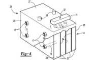
本発明はバッテリとして有効な物品に関し、該物品は、複数のバイポーラプレートの1つ以上のスタックと、バイポーラプレートのスタックの各端に配置される2つのモノポーラプレートとを有し、該モノポーラプレートはバイポーラプレート同士の間に配置された液体電解質を有し、物品は更に1つ以上の次の特徴を有する。すなわち、
1)c)バッテリプレートの1つ以上のスタックが、カソードおよび/またはアノードを備えるプレートの部分を通って横方向に延びる複数のチャネルを備え、および
d)i)チャネルの外周部の回りの1つ以上のシールを有し、該シールはチャネル内への液体電解質の漏洩を防止し、1つ以上のチャネル内に配置されたポストを有し、該ポストの各端部にはオーバーラップ部分が設けられ、該オーバーラップ部分は、チャネルと、横方向チャネルの孔に隣接するモノポーラプレートの外部のシーリング面とをカバーし、かつモノポーラプレートのシーリング面に圧力を加え、該圧力は、バッテリプレートのスタックにより形成される電気化学セルの組立ておよび作動中に発生される圧力に充分耐えることができ、または
ii)1つ以上のチャネル内に配置されたポストを有し、該ポストの各端部は、チャネルと、横方向チャネルの孔に隣接するモノポーラプレートの外部のシーリング面とをカバーする部分を有し、かつモノポーラプレートのシーリング面に圧力を加え、該圧力は、バッテリプレートのスタックにより形成される電気化学セルの組立ておよび作動中に発生される圧力に充分耐えることができ、ポストは、電解質への露出に耐えることができる材料から製造され、ポストは電解質がチャネルに流入することを防止し、
2)c)熱可塑性ポリマからなる膜が、プレートのスタックの縁部の全外周部の回りに配置されて、プレートの縁部の外周部の回りのシールを形成し、該シールは電解質がプレートのスタックの外部に流れることを防止し、
3)セパレータは、その外周部に接着されたシートの形態をなし、フレームはバッテリフレームの基板シートの外周部に隣接して配置され、および
4)c)一体弁および該弁と連通している一体チャネルを更に有している。或る実施形態では、膜は、プレートの縁部の回りで熱可塑性材料のシートを熱融着することにより形成される。或る実施形態では、膜は、プレートの回りの射出成形により形成される。横方向チャネルは、液体電解質がチャネルに流入することを防止するシールを更に有し、またはポストは、チャネルをシールして電解質がチャネルに流入することを防止するように選択される。本発明はバッテリとして有効な物品に関し、バイポーラプレート同士の間に配置された液体電解質を備えた複数のバイポーラプレートを有している。熱可塑性ポリマからなる膜は、プレートのスタックの縁部の全外周部の回りに配置され、プレートのスタックの外周部の回りにシールを形成し、該シールは電解質がプレートのスタックの外部に流出することを防止する。膜は、例えばプレートのスタックの縁部に融着するか、プレートのスタックの回りにモールディングする等の慣用技術を用いて固定される。本発明は、本明細書に開示する物品の製造について説明するプロセスを有している。
The present invention relates to an article useful as a battery, the article having one or more stacks of a plurality of bipolar plates and two monopolar plates disposed at each end of the stack of bipolar plates, the monopolar plates being Having a liquid electrolyte disposed between the bipolar plates, the article further has one or more of the following characteristics. That is,
1) c) 1 or more stacks of battery plates, cathode and / or comprising a plurality of channels extending transversely through a portion of the plate with the anode, and d) i) around the outer peripheral portion of the
2) c) A film of thermoplastic polymer is placed around the entire periphery of the edge of the stack of plates to form a seal around the periphery of the edge of the plate, where the electrolyte is the plate Prevent it from flowing outside the stack,
3) The separator is in the form of a sheet bonded to its outer periphery, the frame is located adjacent to the outer periphery of the battery frame substrate sheet, and 4) c) is in communication with the integral valve and the valve. It further has an integral channel. In some embodiments, the membrane is formed by heat fusing a sheet of thermoplastic material around the edges of the plate. In some embodiments, the membrane is formed by injection molding around the plate. The lateral channel further has a seal that prevents liquid electrolyte from flowing into the channel, or the post is selected to seal the channel and prevent electrolyte from flowing into the channel. The present invention relates to an article useful as a battery, and has a plurality of bipolar plates with a liquid electrolyte disposed between the bipolar plates. A film of thermoplastic polymer is placed around the entire perimeter of the edge of the plate stack, forming a seal around the perimeter of the plate stack, where the electrolyte flows out of the plate stack. To prevent. The membrane is secured using conventional techniques such as fusing to the edge of the stack of plates or molding around the stack of plates. The present invention includes a process that describes the manufacture of the articles disclosed herein.
本発明の物品およびプロセスは更に、本願に開示する選択および他の実施形態を含む任意の組合せの下記特徴の1つ以上を有している。すなわち、モノポーラプレートおよびバイポーラプレートの基板は熱可塑性ポリマからなり、熱可塑性ポリマからなる膜はプレートのスタックの全外周部の回りに配置され、これによりプレートの縁部の回りにシールを形成し、該シールは電解質がプレートのスタックの外部に流出することを防止し、膜は全てのプレートの縁部に融着されて、プレートの外周部の回りにシールを形成し、膜はプレートのスタックの回りにモールディングされ、膜はプレートのスタックの回りに射出成形され、膜の前縁部および後縁部は互いに融着され、膜は、電解質がスタックの内部から膜の外部に流出しないように、プレートの1つ以上のスタックの回りにシールを形成し、物品は横方向チャネルの外周部の回りのシールを有し、該シールは1つ以上の膜からなり、物品は横方向チャネルの外周部の回りのシールを有し、シールは横方向チャネルに沿って、プレートの孔同士の間に配置されたブシュにより形成され、物品は横方向チャネルの外周部の回りのシールを有し、ポストは、オーバーラップ部分を所定位置に保持して充分な構造的一体性を有し、モノポーラプレートのシーリング面に圧力を加えられる任意の材料からなり、物品は横方向チャネルの外周部の回りのシールを有し、ポストは、オーバーラップ部分を所定位置に保持して充分な構造的一体性を有し、モノポーラプレートのシーリング面に圧力を加えられる任意の金属からなり、物品は、横方向チャネルの外周部の回りのシールを備えておらず、ポストは、電解質に露出されたときにその構造的一体性を維持する材料からなり、導電性を有しかつ横方向チャネルをシールして、電解質がチャネルに流入することを防止し、ポストは、プレートのスタックにより形成される電気化学セルの作動温度より高いガラス転移温度または融点を呈するセラミックまたはポリマからなり、ポストはその外面にねじ山を備え、チャネルにはポストを受入れるねじ山が形成され、ポストはチャネルのねじ山内に嵌合され、オーバーラップ部分は、ナットおよび/またはポストの端部のボルトヘッドにより形成され、オーバーラップ部分を備えたポストは1つ以上の熱可塑性ポリマからなりかつ射出成形のようなモールディングにより形成され、ブシュは、各横方向チャネルがスタックを介してシールされるようにして各バッテリプレートの各孔に隣接して配置され、バイポーラプレートは、基板を貫通する複数の開口を備えたポリマ基板からなり、これにより各開口が基板の両面と連通し、1つ以上の開口には導電性材料が充填され、該導電性材料は基板の両面と接触しており、物品は更に逆止弁を有し、該逆止弁は、圧力が物品に損傷を生じさせる圧力より低い所定の圧力レベルに到達したときにバイポーラプレートのシールされたスタック内の圧力を解放でき、ポストは横方向チャネル内で射出成形され、基板は、この外周部の回りに取付けられた熱可塑性ポリマのリボンを備えた熱硬化性ポリマからなり、バッテリプレートの1つ以上のスタックは、
e)カソードペーストおよび/またはアノードペーストが塗布されたプレートの部分を横方向に通る1つ以上のチャネルを有し、および
f)i)チャネル内への液体の漏洩を防止するチャネルの外周部の回りのシールと、各チャネル内に配置されたポストとを有し、各ポストは各端部にオーバーラップ部分を有し、該オーバーラップ部分は、チャネルと、プレートを横方向に貫通する孔に隣接するモノポーラプレートの外部のシーリング面とをカバーしかつモノポーラプレートの外面に圧力を加え、該圧力は、バッテリプレートのスタックにより形成されるセルの組立ておよび作動中に発生される圧力に充分耐えることができ、または
ii)各チャネル内に配置されたポストを有し、各ポストの各端部には、チャネルをカバーしかつプレートを横方向に通る孔に隣接するモノポーラプレートのシーリング面に圧力を加える部分が設けられ、圧力は、バッテリプレートのスタックにより形成されるセルの組立ておよび作動中に発生される圧力に充分耐えることができ、ポストは、電解質への露出に耐えることができかつ電解質がチャネルに流入することを防止する材料から製造され、チャネルの外周部の回りのシールは射出成形により形成され、セパレータは、その外周部の回りに隆起面を備え、バッテリプレートの基板に隣接して配置でき、セパレータはこれを貫通する1つ以上の孔を有し、孔はこの中に配置されたインサートを収容し、該インサートはバッテリプレートの孔内のインサートと協働して、セパレータプレートおよびバッテリプレートのスタックを通るチャネルを形成し、セパレータフレームおよびインサートはセパレータにモールディングされ、セパレータフレームおよびインサートは射出成形され、セパレータフレームおよびインサートはワンピースに射出成形され、バッテリプレートの基板は、これらの外周部の回りに隆起面を有し、セパレータに接着されたフレームに隣接して配置でき、基板の隆起面およびセパレータの回りのフレームは互いに隣接して配置され、これにより外周部は流体が物品内に流入しまたは物品から流出しないようにシールされ、バッテリプレートおよびセパレータは、これらを貫通する1つ以上の孔を有し、該孔は整合して、バッテリプレートおよびセパレータのスタックを通る1つ以上のチャネルを形成し、バッテリプレートおよびセパレータの孔はこれらに配置されたインサートを有し、該インサートはバッテリプレートおよびセパレータのスタックを通る1つ以上のシールされたチャネルを形成し、バッテリプレートおよびセパレータ内のインサートはモールディングにより形成され、バッテリプレートおよびセパレータ内のインサートは射出成形により形成され、充填チャネルまたはベントチャネルはバッテリプレートおよびセパレータプレート内で一体化され、弁が充填チャネルおよびベントチャネル内に一体化されている。
The articles and processes of the present invention further have one or more of the following features in any combination, including options and other embodiments disclosed herein. That is, the monopolar and bipolar plate substrates are made of a thermoplastic polymer, and the film of thermoplastic polymer is placed around the entire outer periphery of the stack of plates, thereby forming a seal around the edges of the plate, The seal prevents electrolyte from flowing out of the stack of plates, the membrane is fused to the edges of all plates to form a seal around the outer periphery of the plates, and the membrane is Molded around, the membrane is injection molded around the stack of plates, the leading and trailing edges of the membrane are fused together, and the membrane prevents the electrolyte from flowing out of the stack to the outside of the membrane Forming a seal around one or more stacks of plates, the article having a seal around the outer periphery of the transverse channel, the seal comprising one or more membranes And the article has a seal around the outer periphery of the transverse channel, the seal is formed by a bush disposed between the holes in the plate along the transverse channel, and the article is the outer periphery of the transverse channel. The post is made of any material that has sufficient structural integrity to hold the overlap portion in place and can apply pressure to the sealing surface of the monopolar plate; Any metal that has a seal around the outer perimeter of the transverse channel, the post has sufficient structural integrity to hold the overlap portion in place, and can apply pressure to the sealing surface of the monopolar plate And the article is not provided with a seal around the outer periphery of the transverse channel and the post is made of a material that maintains its structural integrity when exposed to the electrolyte. Conductive and seals the lateral channel to prevent electrolyte from flowing into the channel, and the post exhibits a glass transition temperature or melting point that is higher than the operating temperature of the electrochemical cell formed by the stack of plates Made of ceramic or polymer, the post is threaded on its outer surface, the channel is threaded to receive the post, the post is fitted within the channel thread, and the overlap portion is the nut and / or post A post formed by a bolt head at the end, with an overlap portion, made of one or more thermoplastic polymers and formed by molding like injection molding, the bushing seals each lateral channel through the stack Bipolar plate placed adjacent to each hole in each battery plate as Consists of a polymer substrate with a plurality of openings through the substrate, whereby each opening communicates with both sides of the substrate, and one or more openings are filled with a conductive material, the conductive material being formed on the substrate. In contact with both sides, the article further has a check valve, which is a sealed stack of bipolar plates when the pressure reaches a predetermined pressure level that is lower than the pressure causing damage to the article The post can be injection molded in the transverse channel and the substrate is made of a thermoset polymer with a ribbon of thermoplastic polymer attached around this outer periphery, one of the battery plates The above stack is
e) having one or more channels running transversely through the portion of the plate coated with the cathode paste and / or anode paste, and f) i) the outer periphery of the channel preventing leakage of liquid into the channel And a post disposed within each channel, each post having an overlap portion at each end, the overlap portion being a channel and a hole penetrating the plate laterally. Covers the outer sealing surface of the adjacent monopolar plate and applies pressure to the outer surface of the monopolar plate, which is sufficiently resistant to the pressure generated during the assembly and operation of the cells formed by the stack of battery plates Or ii) having a post disposed within each channel, each end of each post covering the channel and plate A portion is provided to apply pressure to the sealing surface of the monopolar plate adjacent to the hole passing laterally through, and the pressure is sufficient to withstand the pressure generated during assembly and operation of the cells formed by the stack of battery plates. The post is manufactured from a material that can withstand exposure to the electrolyte and prevent the electrolyte from flowing into the channel, a seal around the outer periphery of the channel is formed by injection molding, and the separator is Having a raised surface around the portion and can be disposed adjacent to the substrate of the battery plate, the separator having one or more holes therethrough, the holes containing the inserts disposed therein, the inserts Cooperates with the insert in the battery plate hole to form a channel through the separator plate and battery plate stack. The separator frame and insert are molded into the separator, the separator frame and insert are injection molded, the separator frame and insert are injection molded in one piece, and the battery plate substrate has a raised surface around these outer peripheries. The raised surface of the substrate and the frame around the separator are arranged adjacent to each other so that the outer periphery does not allow fluid to flow into or out of the article The battery plate and the separator have one or more holes therethrough that are aligned to form one or more channels through the stack of battery plates and separator, Separator holes are placed in these Having an insert, the insert forming one or more sealed channels through the battery plate and separator stack, the insert in the battery plate and separator is formed by molding, and the insert in the battery plate and separator is injected Formed by molding, the fill channel or vent channel is integrated in the battery plate and separator plate, and the valve is integrated in the fill channel and vent channel.
本発明の物品は、1つ以上のバイポーラ電極プレート、好ましくは複数のバイポーラプレートを有している。本明細書で使用する用語「複数」とは、プレートが2つ以上であることを意味する。バイポーラプレートは、2つの対向面を備えたシートの形態の基板からなる。対向面上にはカソードおよびアノードが配置されている。本発明の或る実施形態では、バイポーラプレートはスタックとして物品内に配置され、一方のバイポーラプレートのカソードは他方のバイポーラプレートのアノードに対面するか、アノードを備えたモノポーラプレートおよび各バイポーラプレートのアノードはバイポーラプレートまたはモノポーラプレートのカソードに対面する。物品内では、互いに隣接するアノードとカソードとの間にはスペースが形成され、該スペース内には、アノードおよびカソード対と協働して電気化学セルを形成すべく機能する電解質が収容される。物品の構造は、漏洩およびセルの回路短絡を防止すべく環境からシールされる閉セル構造である。プレートの数は、バッテリの所望電圧を得るべく選択できる。バイポーラバッテリのこの設計は、発生電圧にフレキシビリティを与える。バイポーラプレートは任意の所望断面形状にすることができ、断面形状は使用環境で利用できるパッケージングスペースに適合するように設計できる。断面形状とは、シートの面を遠近法で見た形状をいう。フレキシブルな断面形状およびサイズは、バッテリが使用されるシステムの電圧およびサイズの必要性に適合するように本発明の物品を製造することを可能にする。モノポーラプレートは、プレートのスタックの端セルを形成すべく、プレートのスタックの端部に配置される。モノポーラプレートは、バイポーラプレートに使用されるものと同じ基板、アノードおよびカソードから製造できる。アノードまたはカソードに対面するモノポーラプレートの側面は、別のケースが使用される場合またはスタックの保護に有効なカバーを収容できる場合には裸の基板とすることができる。或る実施形態では、モノポーラプレートに、端セルから外部までプレートを貫通する1つ以上のターミナルを設けることができる。ターミナルは、モノポーラプレートのアノードまたはカソードの極性と一致する。ターミナルは、電気化学セルで発生された電子を、発生された電子を電気の形態で利用するシステムに送る機能を有する。 The article of the present invention has one or more bipolar electrode plates, preferably a plurality of bipolar plates. As used herein, the term “plurality” means that there are two or more plates. The bipolar plate consists of a substrate in the form of a sheet with two opposing surfaces. A cathode and an anode are disposed on the facing surface. In one embodiment of the invention, the bipolar plates are arranged in a stack as a stack, the cathode of one bipolar plate faces the anode of the other bipolar plate, or a monopolar plate with an anode and the anode of each bipolar plate Faces the cathode of the bipolar plate or monopolar plate. Within the article, a space is formed between the anode and cathode adjacent to each other, and within the space is accommodated an electrolyte that functions to cooperate with the anode and cathode pair to form an electrochemical cell. The structure of the article is a closed cell structure that is sealed from the environment to prevent leakage and cell short circuiting. The number of plates can be selected to obtain the desired voltage of the battery. This design of the bipolar battery gives the generated voltage flexibility. The bipolar plate can have any desired cross-sectional shape, and the cross-sectional shape can be designed to fit the packaging space available in the environment of use. The cross-sectional shape is a shape obtained by viewing the sheet surface in perspective. The flexible cross-sectional shape and size allows the article of the invention to be manufactured to meet the voltage and size needs of the system in which the battery is used. A monopolar plate is placed at the end of the stack of plates to form an end cell of the stack of plates. Monopolar plates can be made from the same substrate, anode and cathode used for bipolar plates. The side of the monopolar plate facing the anode or cathode can be a bare substrate if another case is used or if it can accommodate a cover effective to protect the stack. In some embodiments, a monopolar plate can be provided with one or more terminals that penetrate the plate from the end cell to the outside. The terminal matches the polarity of the anode or cathode of the monopolar plate. The terminal has a function of sending electrons generated in the electrochemical cell to a system that uses the generated electrons in the form of electricity.
基板は、バッテリの外面となるバイポーラプレートの回りの電解質密封シールを形成する他のバッテリコンポーネンツと協働し、隣接セル間の電解質の流れを防止するセル隔室としてカソードおよび/またはアノードの支持構造を形成する機能を有し、或る実施形態では電子を一方の表面から他方の表面に伝える。基板は、バッテリの化学的機能に基づいて、種々の材料から形成できる。基板は、バッテリ構造に使用される任意の導電性材料の融点を超える温度に耐え、電解質(例えば硫酸溶液)との接触により基板が劣化しないように、電解質との接触中に高い化学的安定性を有し、所望のバイポーラ電極の背骨を形成する構造的に充分に頑丈な材料から形成される。基板は、適当な材料から形成できおよび/または電気を基板の一方の表面から対向基板の表面に伝えることを可能にする態様で構成されている。基板は、導電性材料例えば金属材料から形成でき、または非導電性材料から形成できる。非導電性材料の例として、熱硬化性ポリマ、弾性ポリマまたは熱可塑性ポリマまたはこれらの組合せのようなポリマがある。或る実施形態では、非導電性基板は、この中またはこの上に導電性の特徴をもたせることができる。採用できるポリマ材料の例として、ポリアミド、ポリエステル、ポリスチレン、ポリエチレン(ポリエチレンナフタレート、高密度ポリエチレンおよび低密度ポリエチレンを含む)、ポリカーボネート(PC)、ポリプロピレン、ポリ塩化ビニル、バイオベースプラスチック/バイオポリマ(例えば、ポリ乳酸)、シリコーン、アクリロニトリルブタジエンスチレン(ABS)または例えばPC/ABS(ポリカーボネートとアクリロニトリル−ブタジエン−スチレンとのブレンド)のようなこれらの任意の組合せがある。複合基板を使用することもでき、複合材には、当業界で知られたファイバまたは充填材のような強化材料、熱硬化性ポリマの外周部の回りの熱硬化性コアおよび熱可塑性シェルまたは熱可塑性縁部または非導電性ポリマ内に配置される導電性材料等の2つの異なるポリマ材料がある。好ましい実施形態では、基板は、プレートの縁部に、接着可能、好ましくは融着可能な熱可塑性材料を設けられる。一実施形態では、基板は、バイポーラプレートのスタッキングおよび電気化学セルの形成を容易にすべく、外周部の回りに隆起縁部を設けることができる。本明細書で使用される用語「隆起縁部」は、プレートの2つの対向表面のうちの少なくとも一方の表面の隆起縁部を意味する。隆起縁部は、他方の基板材料の周囲りに形成される熱可塑性縁部で形成できる。隆起縁部は、本明細書で説明するセパレータプレートとして機能できる。基板または基板の外周部は、好ましくは非導電性材料および熱可塑性材料で形成される。セパレータの回りのフレームまたはセパレータ上に一体化されるフレームは、好ましくは非導電性材料および熱可塑性材料で形成される。非導電性材料の使用により、バッテリスタックの外面のシーリングを高めることができる。 The substrate cooperates with other battery components to form an electrolyte hermetic seal around the bipolar plate that provides the outer surface of the battery, and supports the cathode and / or anode as a cell compartment that prevents electrolyte flow between adjacent cells. In some embodiments, electrons are transferred from one surface to the other. The substrate can be formed from a variety of materials based on the chemical function of the battery. The substrate withstands temperatures above the melting point of any conductive material used in the battery structure, and has high chemical stability during contact with the electrolyte so that the substrate does not deteriorate due to contact with the electrolyte (eg sulfuric acid solution) And is formed from a structurally sufficiently robust material that forms the backbone of the desired bipolar electrode. The substrate can be formed from a suitable material and / or configured in a manner that allows electricity to be transferred from one surface of the substrate to the surface of the counter substrate. The substrate can be formed from a conductive material, such as a metal material, or can be formed from a non-conductive material. Examples of non-conductive materials are polymers such as thermosetting polymers, elastic polymers or thermoplastic polymers or combinations thereof. In some embodiments, the non-conductive substrate can have conductive features therein or thereon. Examples of polymer materials that can be employed include polyamide, polyester, polystyrene, polyethylene (including polyethylene naphthalate, high density polyethylene and low density polyethylene), polycarbonate (PC), polypropylene, polyvinyl chloride, bio-based plastic / biopolymer (eg , Polylactic acid), silicone, acrylonitrile butadiene styrene (ABS) or any combination of these, such as PC / ABS (blend of polycarbonate and acrylonitrile-butadiene-styrene). Composite substrates can also be used, including composite materials such as fibers or fillers known in the art, a thermosetting core and a thermoplastic shell or heat around the periphery of the thermosetting polymer. There are two different polymer materials, such as a conductive material disposed within a plastic edge or non-conductive polymer. In a preferred embodiment, the substrate is provided on the edge of the plate with an adhesive material, preferably a fusible thermoplastic material. In one embodiment, the substrate can be provided with a raised edge around the periphery to facilitate bipolar plate stacking and electrochemical cell formation. As used herein, the term “raised edge” means a raised edge on at least one of the two opposing surfaces of the plate. The raised edge can be formed with a thermoplastic edge formed around the other substrate material. The raised edge can function as a separator plate as described herein. The substrate or the outer periphery of the substrate is preferably formed of a non-conductive material and a thermoplastic material. The frame around the separator or the frame integrated on the separator is preferably formed of a non-conductive material and a thermoplastic material. The use of a non-conductive material can increase the sealing of the outer surface of the battery stack.
或る実施形態では、基板は、1つ以上の開口が形成されたほぼ非導電性の物質(例えば誘電物質)からなる。開口は、機械加工(例えばフライス加工)され、基板の製造中(例えばモールディングまたはシェーピングによる製造中)に形成されまたは他の方法により形成される。基板に形成される開口のサイズおよび密度は、バッテリの抵抗に影響を与える。開口は少なくとも約0.2mmの直径をもつように形成される。開口は、約5mm以下の直径に形成できる。開口は、約1.4mm〜約1.8mmの直径に形成できる。開口は、少なくとも約0.02個/cm2の密度をもつように形成できる。開口は、約4個/cm2より小さい密度をもつように形成できる。開口は、約2.0個/cm2〜約2.8個/cm2の密度をもつように形成できる。開口には、導電性材料、例えば金属含有材料を充填できる。導電性材料は、基板の熱劣化温度より低い温度で相変態を受け、したがって相変態温度より低いバッテリ組立体の作動温度で、誘電体基板が、基板の第1表面と第2表面との間の材料夾雑物による導電性経路を有するような材料である。また、相変態温度より高い温度では、導電性材料の夾雑物が、導電性経路を通る導電性を不能にする相変態を受ける。例えば、導電性材料として、鉛、錫、ニッケル、リチウム、アンチモニ、銅、ビスマス、インジウムまたは銀のうちの少なくとも1つまたは任意の2つ以上の混合物からなるソルダ材料がある。導電性材料は、鉛が実質的に全く存在しない(せいぜい微量の鉛を含有)もので構成するか、機能的に作動する両の鉛を含有するもので構成できる。材料には、鉛および錫の混合物を含めることができる。例えば、材料は、大部分が錫で小部分が鉛(例えば、約55〜約65重量部の錫および約35〜約45重量部の鉛)のもので構成できる。材料は、約240℃、230℃、220℃、210℃または約200℃より低い融点(例えば、約180℃〜約190℃の範囲内の融点)を呈するものとすることができる。材料には、共晶混合物を含めることができる。開口を充填する導電性材料としてソルダを使用することの特徴は、ソルダが、バッテリの連続作動にとって安全でない温度で溶融すべく、使用されるソルダの種類に基づいた一定の適合融点を有することである。ひとたびソルダが溶融すると、溶融したソルダを収容する基板開口は、もはや導電性をもたず、電極プレート内に開回路が形成される。開回路はバイポーラバッテリ内の抵抗を劇的に増大させ、これにより、更に電流が流れることを停止し、バッテリ内の安全でない反応を遮断する。したがって、開口を充填すべく選択された導電性材料の種類は、バッテリ内部でのこのような内部遮断機構を設ける必要があるか否か、およびこの必要がある場合に、内部遮断を行う温度は何度を望むのかに基づいて変えることができる。基板は、所定条件を超える作動条件の場合には、基板が、これを通る導電性を破壊することによりバッテリの作動を不能にすべく機能するように構成されている。例えば、誘電体基板の孔を充填する導電性材料は相変態を受ける(例えば、溶融する)ため、基板の導電性が破壊される。破壊の程度は、基板の導電性機能を部分的に不能にするか、全体的に不能にすることもある。 In some embodiments, the substrate comprises a substantially non-conductive material (eg, a dielectric material) having one or more openings formed therein. The openings are machined (eg, milled), formed during manufacture of the substrate (eg, during manufacturing by molding or shaping), or otherwise formed. The size and density of the openings formed in the substrate affects the resistance of the battery. The opening is formed to have a diameter of at least about 0.2 mm. The opening can be formed with a diameter of about 5 mm or less. The opening can be formed to a diameter of about 1.4 mm to about 1.8 mm. Opening may be formed to have a density of at least about 0.02 / cm 2. The openings can be formed to have a density less than about 4 / cm 2 . The openings can be formed to have a density of about 2.0 / cm 2 to about 2.8 / cm 2 . The opening can be filled with a conductive material, such as a metal-containing material. The conductive material undergoes a phase transformation at a temperature below the thermal degradation temperature of the substrate, and therefore, at a battery assembly operating temperature below the phase transformation temperature, the dielectric substrate is between the first surface and the second surface of the substrate. It is a material having a conductive path due to foreign materials. Also, at temperatures higher than the phase transformation temperature, impurities in the conductive material undergo a phase transformation that disables the conductivity through the conductive path. For example, as the conductive material, there is a solder material made of at least one of lead, tin, nickel, lithium, antimony, copper, bismuth, indium or silver, or a mixture of any two or more. The conductive material can be composed of material that is substantially free of lead (containing at most trace amounts of lead) or that contains both functionally active leads. The material can include a mixture of lead and tin. For example, the material can comprise a majority of tin and a minor portion of lead (eg, about 55 to about 65 parts by weight tin and about 35 to about 45 parts by weight lead). The material can exhibit a melting point lower than about 240 ° C., 230 ° C., 220 ° C., 210 ° C. or about 200 ° C. (eg, a melting point in the range of about 180 ° C. to about 190 ° C.). The material can include a eutectic mixture. The feature of using solder as the conductive material that fills the opening is that the solder has a certain compatible melting point based on the type of solder used to melt at a temperature that is unsafe for continuous operation of the battery. is there. Once the solder has melted, the substrate opening that accommodates the melted solder is no longer conductive and an open circuit is formed in the electrode plate. The open circuit dramatically increases the resistance in the bipolar battery, thereby stopping further current flow and blocking unsafe reactions in the battery. Therefore, the type of conductive material selected to fill the opening determines whether such an internal shut-off mechanism needs to be provided inside the battery, and if so, the temperature at which internal shut-off is You can change it based on how many times you want. The substrate is configured to function to disable battery operation by destroying the conductivity therethrough in the event of operating conditions exceeding a predetermined condition. For example, the conductive material filling the holes in the dielectric substrate undergoes a phase transformation (eg, melts), thereby destroying the conductivity of the substrate. The degree of destruction may partially or completely disable the conductive function of the substrate.
バイポーラプレート一方の面および幾つかのモノポーラプレートには1つ以上のカソードが配置される。カソードは、バッテリのカソードとして機能できかつバッテリに普通に使用される任意の形態で機能できる任意の材料で作られる。カソードは正極活物質とも呼ばれている。正極活物質は、リチウムイオン二次電池、ニッケル金属水素化物二次電池または鉛酸(lead acid)二次電池に一般的に使用される複合酸化物、スルフェート配合物、またはリチウム、鉛またはホスフェート配合物または遷移金属で形成できる。複合酸化物の例として、例えばLiCoO2のようなLi/Coベース複合酸化物、LiNiO2のようなLi/Niベース複合酸化物、LiMn2O4のようなLi/Mnベース複合酸化物、およびLiFeO2のようなLi/Feベース複合材料がある。遷移金属およびリチウムの例示ホスフェート配合物およびサルファ配合物として、LiFePO4、V2O5、MnO2、TiS2、MoS2、MoO3、PbO2、AgO、NiOOH等がある。カソード材料は、電気化学セルのカソードとして機能できる任意の形態にすることができる。例示の形態として、ペースト形態で成形された部品、プレハブ型シートまたはフィルムがある。鉛酸バッテリの好ましいカソード材料として二酸化鉛(PbO2)がある。アノードは、バイポーラプレートの両面および他のモノポーラプレート上に配置されている。アノードは負極活物質と呼ばれている。本発明の組立体には、任意のアノードおよびアノード材料を使用できる。アノード材料は、鉛酸、ニッケル金属水素化物およびリチウムイオンバッテリ二次電池に使用される任意の材料を含む。アノードの構成に有効な例示材料として、鉛、およびカーボンまたはリチウムの複合酸化物(例えば、酸化チタンまたはチタンおよびリチウムの複合酸化物)および遷移金属がある。好ましい鉛酸アノード材料はスポンジ状鉛である。カソード材料は、電気化学セルのカソードとして機能できる任意の形態にすることができる。例示の形態として、ペースト形態で成形された部品、プレハブ型シートまたはフィルムがある。ペースト組成物には、強化用フロックまたはガラス繊維、ペースト安定性増強用のリガノ有機化合物(ligano-organic compounds)、特に負極活物質用のカーボンのような導電性添加剤を含めることができる。鉛酸バッテリ用のアノード材料の好ましい形態はスポンジ状鉛である。アノードおよびカソードは、ひとたびセルを含む回路が形成されたときに、協働して電気化学セルとして機能するものが選択される。 One or more cathodes are disposed on one side of the bipolar plate and some monopolar plates. The cathode is made of any material that can function as the cathode of the battery and can function in any form commonly used in batteries. The cathode is also called a positive electrode active material. The positive electrode active material is a composite oxide, sulfate compound, or lithium, lead or phosphate compound commonly used in lithium ion secondary batteries, nickel metal hydride secondary batteries or lead acid secondary batteries. Or transition metal. Examples of composite oxides, for example Li / Co based composite oxide such as LiCoO 2, Li / Ni based composite oxide such as LiNiO 2, Li / Mn based composite oxide such as LiMn 2 O 4, and There are Li / Fe-based composite materials such as LiFeO 2 . Exemplary phosphate and sulfur formulations of transition metals and lithium include LiFePO 4 , V 2 O 5 , MnO 2 , TiS 2 , MoS 2 , MoO 3 , PbO 2 , AgO, NiOOH, and the like. The cathode material can be in any form that can function as the cathode of an electrochemical cell. Exemplary forms include parts molded in paste form, prefabricated sheets or films. A preferred cathode material for lead acid batteries is lead dioxide (PbO 2 ). The anode is disposed on both sides of the bipolar plate and on other monopolar plates. The anode is called a negative electrode active material. Any anode and anode material can be used in the assembly of the present invention. The anode material includes any material used for lead acid, nickel metal hydride and lithium ion battery secondary batteries. Exemplary materials useful for anode construction include lead and carbon or lithium composite oxides (eg, titanium oxide or titanium and lithium composite oxides) and transition metals. A preferred lead acid anode material is sponge lead. The cathode material can be in any form that can function as the cathode of an electrochemical cell. Exemplary forms include parts molded in paste form, prefabricated sheets or films. The paste composition may include conductive additives such as reinforcing flocs or glass fibers, ligano-organic compounds for enhancing paste stability, especially carbon for negative electrode active materials. The preferred form of anode material for lead acid batteries is sponge lead. The anode and cathode are selected to work together as an electrochemical cell once a circuit containing the cell is formed.
本発明の組立体は更にセパレータを有している。セパレータは、電気化学セルのアノードとカソードとの間に配置され、より詳しくは、バイポーラプレート同士の間またはバイポーラプレートとモノポーラプレートとの間に配置される。好ましくは、セパレータは、隣接するカソードおよびアノードの領域より大きい領域を有する。好ましくはセパレータは、セルのカソード部分とアノード部分とを完全に分離する。セルのカソード部分とアノード部分とを完全に分離するため、セパレータの縁部は、好ましくは、アノードまたはカソードが配置されていないバイポーラプレートおよびモノポーラプレートの外周縁部と接触する。バッテリセパレータは、電気化学セルを隔離し、樹脂状結晶の形成によるセルの短絡を防止し、かつ液体電解質、イオン、電子またはこれらの任意の組合せがセパレータを通過できるようにする機能を有している。列挙した機能の1つ以上を遂行する既知の任意のバッテリセパレータは、本発明の組立体に使用できる。セパレータは、多孔質ポリマフィルム、ガラスマット、多孔質ゴム、イオン伝導性ゲル等の非電導性材料、または木のような天然材料等から作るのが好ましい。セパレータは、電解質、イオン、電子またはこれらの組合せが通ることができる多孔または曲がりくねった経路を有することが好ましい。セパレータとして有効なより好ましい材料として、吸収剤ガラスマットおよび多孔質超高分子量ポリオレフィン膜等がある。 The assembly of the present invention further includes a separator. The separator is disposed between the anode and the cathode of the electrochemical cell, and more specifically between the bipolar plates or between the bipolar plate and the monopolar plate. Preferably, the separator has a region that is larger than the region of the adjacent cathode and anode. Preferably, the separator completely separates the cathode and anode portions of the cell. In order to completely separate the cathode and anode portions of the cell, the edge of the separator is preferably in contact with the outer periphery of the bipolar and monopolar plates where the anode or cathode is not located. The battery separator has the function of isolating the electrochemical cell, preventing the cell from short circuiting due to the formation of resinous crystals, and allowing liquid electrolyte, ions, electrons or any combination thereof to pass through the separator. Yes. Any known battery separator that performs one or more of the listed functions can be used in the assembly of the present invention. The separator is preferably made of a non-conductive material such as a porous polymer film, glass mat, porous rubber, ion conductive gel, or a natural material such as wood. The separator preferably has a porous or tortuous path through which electrolytes, ions, electrons, or combinations thereof can pass. More preferable materials effective as a separator include an absorbent glass mat and a porous ultrahigh molecular weight polyolefin film.
或る実施形態では、本発明の物品は更に、金属シートまたは箔を有している。金属シートまたは箔は、電気化学セル内を流れる電子を分散させて、活性材料を基板に確実に電気的接続すべく機能し、或る実施形態では、集電体として機能する。或る実施形態では、バッテリは電子を正のバッテリターミナルに伝える電流導体を有し、これらの実施形態では、金属シートまたは箔が電子を電流導体に導く。金属シートまたは箔は任意の導電性金属から作ることができ、好ましい導電性金属として、銀、錫、銅および鉛がある。金属の選択は、アノードおよびカソードの材料により影響を受ける。鉛酸バッテリの場合には、鉛シートまたは鉛泊が好ましい。金属シートまたは箔は、アノードまたはカソードと基板との間に配置するのが好ましい。金属シートまたは箔は、基板に取付けられる。セルの環境内で金属シートまたは箔を基板に保持すべく基板に取付けるのに、溶接または接着剤による接合等の任意の方法を使用できる。金属シートまたは箔は、接着剤により基板に接合するのが好ましい。この接合に有効な好ましい接着剤として、エポキシ、ゴムセメント、フェノール樹脂、ニトリルゴム化合物またはシアノアクリレート接着剤がある。金属シートまたは箔は、アノードまたはカソードおよび基板の全面の間に配置されるのが好ましい。金属シートおよび箔は、基板の全面をカバーする。アノードまたはカソードがペースト状の形態をなす実施形態では、ペーストは金属箔またはシートに塗布される。金属シートまたは箔は1つ以上の電流導体に接触して、電子を電流導体に伝える。金属シートおよび箔は、セルを通って流れる電子を分散させるのに充分な厚さで、電子を収集して電子をセル内の電流導体に伝えるのに適した厚さに選択される。金属シートまたは箔は、好ましくは約0.75mm以下、より好ましくは約0.2mm以下、最も好ましくは約0.1mm以下の厚さを有する。好ましくは、金属シートまたは箔は、好ましくは約0.025mm以上、より好ましくは約0.050mm以上、最も好ましくは約0.075mm以上の厚さを有する。 In certain embodiments, the article of the present invention further comprises a metal sheet or foil. The metal sheet or foil functions to disperse the electrons flowing in the electrochemical cell to ensure that the active material is electrically connected to the substrate, and in one embodiment, functions as a current collector. In some embodiments, the battery has a current conductor that conducts electrons to the positive battery terminal, and in these embodiments, a metal sheet or foil guides the electrons to the current conductor. The metal sheet or foil can be made from any conductive metal, and preferred conductive metals include silver, tin, copper and lead. The choice of metal is influenced by the anode and cathode materials. In the case of a lead acid battery, a lead sheet or lead stay is preferred. The metal sheet or foil is preferably disposed between the anode or cathode and the substrate. A metal sheet or foil is attached to the substrate. Any method such as welding or adhesive bonding can be used to attach the metal sheet or foil to the substrate to hold it to the substrate within the environment of the cell. The metal sheet or foil is preferably bonded to the substrate with an adhesive. Preferred adhesives effective for this bonding include epoxy, rubber cement, phenolic resin, nitrile rubber compound or cyanoacrylate adhesive. The metal sheet or foil is preferably disposed between the anode or cathode and the entire surface of the substrate. The metal sheet and foil cover the entire surface of the substrate. In embodiments where the anode or cathode is in the form of a paste, the paste is applied to a metal foil or sheet. The metal sheet or foil contacts one or more current conductors and conducts electrons to the current conductors. The metal sheet and foil are selected to have a thickness sufficient to disperse the electrons flowing through the cell and to a thickness suitable for collecting the electrons and transferring them to the current conductor in the cell. The metal sheet or foil preferably has a thickness of about 0.75 mm or less, more preferably about 0.2 mm or less, and most preferably about 0.1 mm or less. Preferably, the metal sheet or foil preferably has a thickness of about 0.025 mm or more, more preferably about 0.050 mm or more, and most preferably about 0.075 mm or more.
本発明の組立体におけるコンポーネンツのスタックには、コンポーネンツを通る横方向チャネルおよび液体電解質を収容する電気化学セル用に形成される領域を設けることができる。スタックは、バイポーラプレート、モノポーラプレート、セパレータ、アノード、カソード、任意の金属シートおよび使用されるスタックの他のコンポーネンツを有している。横方向チャネルはポストを収容する機能を有し、幾つかのチャネルは、横方向冷却チャネルまたはベント/充填チャネルとして機能すべく、非充填のまま残される。本発明の或る実施形態では、チャネルは、アノード、カソードおよび電解質を収容したセルを通る。チャネルは、電解質および作動中に発生されるガスがチャネルに流入することを防止すべくシールされる。この目的を達成できる任意のシーリング方法を使用できる。チャネルのサイズおよび形状は、端プレートおよび基板の縁部を支持するポストを収容して、電解質および作動中に発生されるガスがチャネルに流入することを防止しかつ作動中に生じる圧縮力によりコンポーネンツおよび個々の電気化学セルのシールが損傷を受けることを防止できる任意のサイズおよび形状にすることができる。チャネルの形状は、円形、楕円形、または正方形、長方形、六角形等の多角形にするのが好ましい。チャネルのサイズは、使用されるポストを収容できるように選択される。実用的なチャネルは、形成されたチャネルにポストを配置できるようにまたは冷却のためにチャネルを通して流体を流すことができるようにコンポーネンツに配置された一連の孔を有している。チャネルの数は、端プレートおよび基板の縁部を支持し、電解質および作動中に発生されるガスの漏洩を防止し、かつ作動中に生じる圧縮力がコンポーネンツおよび個々の電気化学セルのシールに損傷を与えることを防止するように選択される。作動中に生じる圧縮力を分散させるには、複数のチャネルを設けるのが好ましい。チャネルの数および設計により、シールの疲労強度を超える縁部応力を充分に最小にできる。チャネルの位置は、作動中に発生される圧縮力を分散させるように選択される。応力により良く対処するには、チャネルを幾分均一に分散させるのが好ましい。チャネルは、好ましくは約2mm以上、より好ましくは約4mm以上、最も好ましくは約6mm以上の横断面サイズを有する。チャネルの横断面サイズの上限は実用的に定められ、サイズが大き過ぎると組立体の効率が低下される。チャネルの好ましい横断面サイズは約12mm以下、最も好ましくは約10mm以下である。 The stack of components in the assembly of the present invention can be provided with lateral channels through the components and regions formed for the electrochemical cell containing the liquid electrolyte. The stack has bipolar plates, monopolar plates, separators, anodes, cathodes, optional metal sheets and other components of the stack used. The transverse channels have the function of accommodating posts, and some channels are left unfilled to function as transverse cooling channels or vent / fill channels. In certain embodiments of the invention, the channel passes through a cell containing an anode, a cathode and an electrolyte. The channel is sealed to prevent electrolyte and gas generated during operation from entering the channel. Any sealing method that can achieve this goal can be used. The channel size and shape accommodates the end plates and posts that support the edges of the substrate to prevent electrolyte and gas generated during operation from flowing into the channel and due to the compressive forces generated during operation. And any size and shape that can prevent the individual electrochemical cell seals from being damaged. The shape of the channel is preferably a circle, an ellipse, or a polygon such as a square, rectangle, or hexagon. The size of the channel is selected to accommodate the post used. A practical channel has a series of holes arranged in the components so that posts can be placed in the formed channel or fluid can flow through the channel for cooling. The number of channels supports the edge of the end plate and substrate, prevents leakage of electrolyte and gas generated during operation, and the compressive force generated during operation damages the seals of the components and individual electrochemical cells Selected to prevent giving. In order to disperse the compressive force generated during operation, it is preferable to provide a plurality of channels. The number and design of channels can sufficiently minimize edge stresses that exceed the fatigue strength of the seal. The position of the channel is selected to distribute the compressive force generated during operation. To better cope with stress, it is preferable to distribute the channels somewhat uniformly. The channel preferably has a cross-sectional size of about 2 mm or greater, more preferably about 4 mm or greater, and most preferably about 6 mm or greater. The upper limit of the channel cross-sectional size is practically determined, and if the size is too large, the efficiency of the assembly is reduced. The preferred cross-sectional size of the channel is about 12 mm or less, most preferably about 10 mm or less.
少なくとも幾つかのチャネルには、次の機能、すなわち、コンポーネンツへの損傷またはスタックのコンポーネンツの縁部間のシールの破壊を防止する態様でコンポーネンツのスタックを一体に保持する機能、セパレータ材料を横切る均一な圧縮を確保する機能、およびセパレータ材料の均一な厚さを確保する機能の1つ以上を遂行するポストが配置されている。ポストの各端部には、モノポーラの端プレートの外表面と係合するオーバーラップ部分を設けるのが好ましい。このオーバーラップ部分は、コンポーネンツへの損傷またはスタックのコンポーネンツの縁部間のシールの破壊を防止し、かつバッテリ作動中のスタックの膨張または他の変位を防止する態様で、モノポーラ端プレートの外表面に圧力を加えるべく機能する。オーバーラップ部分はシール面と接触しており、端プレートの部分はオーバーラップ部分と接触している。或る実施形態では、スタックはモノポーラ端プレート上に別の構造的保護端ピースを有し、オーバーラップ部分は構造的保護端ピースの外表面と接触している。オーバーラップ部分は、ポストと協働して、コンポーネンツへの損傷またはスタックのコンポーネンツの縁部間のシールの破壊を防止する任意の構造とすることができる。例示のオーバーラップ部分は、ボルトヘッド、モールディングされたヘッド、貝折れ釘(brads)、コッタピン、シャフトカラー等を含む。ポストは、全スタックを貫通する長さを有し、このような長さはバッテリの所望のキャパシタンスに基づいて変えられる。ポストは、チャネルを充填する横断面形状およびサイズを有するのが好ましい。ポストの数は、端プレートおよび基板の縁部を支持すべく選択され、電解質および作動中に発生されるガスの漏洩を防止し、作動中に生じる圧縮力によってコンポーネンツおよび個々の電気化学セルのシールが損傷されることを防止し、シールの疲労強度を超える縁部応力を最小にする。作動中に発生される圧縮力を分散させるには、複数のポストが存在することが好ましい。1つ以上のチャネルが冷却チャネルまたはベント/充填チャネルとして使用される場合には、より少数のポストにすることができる。ポストは、必要な機能を遂行する任意の材料で構成できる。ポストがチャネルのシールに使用される場合には、使用される材料は、セルの作動条件に耐え、電解質に露出されたときに腐食せず、かつセルの作動中に発生される温度および圧力に耐えることができるものが選択される。ポストがシーリング機能を遂行する場合には、ポストは、列挙した条件に耐え得るポリマ材料またはセラミック材料で形成するのが好ましい。この実施形態では、セルの短絡を防止するため、材料は非導電性でなくてはならない。本明細書で説明するように、ポストは熱可塑性材料からなるのが好ましい。好ましい熱可塑性材料として、ABS、ポリプロピレン、ポリエステル、熱可塑性ポリウレタン、ポリオレフィン、配合熱可塑性樹脂、ポリカーボネート等がある。ABSが最も好ましい。チャネルが別々にシールされる場合には、ポストは、所望の機能を遂行する構造的一体性を有する任意の材料で構成できる。列挙した上記ポリマ材料、セラミックおよび金属を使用できる。適当な金属として、鋼、黄銅、アルミニウム、銅等がある。ポストには、モールディングされたポスト、ねじ山付きポストまたは1つ以上のアタッチメントを備えたポストがある。部品にねじ山が形成されている場合には、ねじ山付きポストを受入れるためのねじ山がスタックの構造部品に形成されている。ポストには、その一端にヘッド、ナット、他端に貝折れ釘またはコッタピン用の孔を設けるか、ヘッド、ナット、貝折れ釘またはコッタピン用の孔を両端に設けることができる。これは、モールド成形されないポストについては一般的にいえることである。ポストは、短縮できるが伸長できない一方ラチェッティングとなるように構成できる。このようなポストが所定位置に配置されると、スタックが圧縮されかつポストが短縮されて、ポストはスタックに圧力を維持する。この実施形態におけるポストには、ポストがジッパのような構造の一方部分として機能できるようにするラチェッティングを容易にする隆起部を設けることができる。所定位置において隣接するプレートを圧縮するため、マッチングナットおよび/またはワッシャをポストに使用することができる。ナットおよび/またはワッシャはポスト上で一方向に移動し、ナットおよび/またはワッシャがポストに沿って他方向に移動することを防止する。使用時に、列挙した機能を遂行するため、ポストには適当な貝折れ釘、コッタピン等を設けることができる。ポストがモールディング成形される場合には、別々にまたは所定位置でモールディングすることができる。本来の所定位置でモールディングする場合には、溶融プラスチックを所定位置に保持するため、チャネル内にシールを設ける必要がある。ねじ山が形成された非導電性ポストを使用して必要なシールを行うことができる。或いは、予成形非導電性ポリマポストは、チャネルをシールする態様でチャネル内に締り嵌めを形成するように設計できる。ポストは、射出成形のようなモールディングにより、所定位置で成形できる。 At least some of the channels have the following functions: the ability to hold the stack of components together in a manner that prevents damage to the components or failure of the seal between the edges of the stack components, uniform across the separator material Posts are disposed that perform one or more of the functions of ensuring proper compression and ensuring the uniform thickness of the separator material. Each end of the post is preferably provided with an overlap portion that engages the outer surface of the monopolar end plate. This overlapping portion prevents damage to the components or failure of the seal between the edges of the stack components, and prevents the expansion or other displacement of the stack during battery operation in a manner that prevents the outer surface of the monopolar end plate. Function to apply pressure to The overlap portion is in contact with the sealing surface, and the end plate portion is in contact with the overlap portion. In some embodiments, the stack has another structural protective end piece on the monopolar end plate, and the overlap portion is in contact with the outer surface of the structural protective end piece. The overlap portion can be any structure that cooperates with the post to prevent damage to the components or failure of the seal between the edges of the components of the stack. Exemplary overlapping portions include bolt heads, molded heads, brads, cotter pins, shaft collars, and the like. The post has a length that extends through the entire stack, and such length can be varied based on the desired capacitance of the battery. The post preferably has a cross-sectional shape and size that fills the channel. The number of posts is selected to support the edge of the end plate and substrate, preventing leakage of electrolyte and gas generated during operation, and sealing of components and individual electrochemical cells by the compressive force generated during operation. Is prevented from being damaged, and the edge stress exceeding the fatigue strength of the seal is minimized. There are preferably a plurality of posts to disperse the compressive force generated during operation. There can be fewer posts if more than one channel is used as a cooling channel or vent / fill channel. The post can be composed of any material that performs the required function. If posts are used to seal the channel, the materials used will withstand the operating conditions of the cell, will not corrode when exposed to the electrolyte, and will be subject to the temperature and pressure generated during cell operation. One that can withstand is selected. If the post performs a sealing function, the post is preferably formed of a polymer or ceramic material that can withstand the listed conditions. In this embodiment, the material must be non-conductive to prevent cell shorting. As described herein, the post is preferably made of a thermoplastic material. Preferred thermoplastic materials include ABS, polypropylene, polyester, thermoplastic polyurethane, polyolefin, compounded thermoplastic resin, polycarbonate and the like. ABS is most preferred. If the channels are sealed separately, the post can be composed of any material that has structural integrity to perform the desired function. The above listed polymer materials, ceramics and metals can be used. Suitable metals include steel, brass, aluminum, copper and the like. Posts can be molded posts, threaded posts, or posts with one or more attachments. If the part is threaded, a thread for receiving the threaded post is formed on the structural part of the stack. The post can be provided with a head and nut at one end and a hole for a shell nail or cotter pin at the other end, or a hole for a head, nut, shell nail or cotter pin at both ends. This is generally true for posts that are not molded. The post can be configured to be ratcheting while it can be shortened but not extended. When such a post is in place, the stack is compressed and the post is shortened so that the post maintains pressure on the stack. The post in this embodiment can be provided with a ridge that facilitates ratcheting that allows the post to function as one part of a zipper-like structure. Matching nuts and / or washers can be used on the posts to compress adjacent plates in place. The nut and / or washer moves in one direction on the post and prevents the nut and / or washer from moving in the other direction along the post. In use, the post can be provided with suitable shell nails, cotter pins, etc. to perform the listed functions in use. If the post is molded, it can be molded separately or in place. When molding in the original predetermined position, it is necessary to provide a seal in the channel in order to hold the molten plastic in the predetermined position. The necessary seals can be made using threaded non-conductive posts. Alternatively, the pre-formed non-conductive polymer post can be designed to form an interference fit within the channel in a manner that seals the channel. The post can be molded at a predetermined position by molding such as injection molding.
組立てられたとき、バイポーラプレートおよびモノポーラプレートを含むコンポーネンツのスタックは、シールされた電気化学セルを形成する。シールされたセル内には液体電解質が配置される。電解質は、使用されるアノードおよびカソードとの電気化学的反応を行う任意の液体電解質で構成できる。電解質は、電子およびイオンがアノードとカソードとの間を流れることを可能にする。電解質は、水ベースまたは有機物ベースの電解質とすることができる。本発明で有効な有機物ベース電解質として、有機溶剤中に溶解された電解質塩がある。リチウムイオン二次電池においては、リチウムを電解質塩中に含める必要がある。例えば、リチウム含有電解質として、LiPF6、LiClO4、LiBF4、LiAsF6、LiSO3CF3およびLiN(CF3SO2)2がある。これらの電解質塩は単独で使用するか、2つ以上の組合せで使用することもできる。有機溶剤は、セパレータ、カソード、アノードおよび電解質塩と相容性のあるものでなくてはならない。有機溶剤は、高電圧を印加しても分解されないものを使用するのが好ましい。例えば、エチレンカーボネート(EC)、プロピレンカーボネート(PC)、ブチレンカーボネート、ジメチルカーボネート(DMC)、ジエチルカーボネートおよびエチルメチルカーボネート等のカーボネート、テトラヒドロフラン(THF)および2−メチルテトラヒドロフラン等の環状エーテル、1,3−ジオキソランおよび4−メチルジオキソラン等の環状エステル、γ−ブチロラクトン、スルホラン、3−メチルスルホラン、ジメトキシエタン、ジエトキシエタン、エトキシメトキシメタンおよびエチルジグリム等のラクトンを使用するのが好ましい。これらの溶剤は単独で、または2つ以上を組合せて使用できる。液体電解質中の電解質の濃度は、0.3〜5mol/lであるのが好ましい。通常、電解質は、1mol/lの近傍で最高の導電性を呈する。液体電解質は、電解質の30〜70重量%、特に40〜60重量%を占めるのが好ましい。水性電解質は、セルの機能を高める酸または塩を水中に有する。好ましい塩および酸として、硫酸、硫酸ナトリウムまたは硫酸カリウムの塩がある。塩または酸は、セルが作動を行うのに充分な量で存在する。濃度は、電解質の重量に基づいて、約0.5重量%以上、より好ましくは約1.0重量%以上、最も好ましくは約1.5重量%以上である。鉛酸バッテリの好ましい電解質は、硫酸水溶液である。 When assembled, the stack of components including the bipolar plate and the monopolar plate forms a sealed electrochemical cell. A liquid electrolyte is disposed in the sealed cell. The electrolyte can consist of any liquid electrolyte that undergoes an electrochemical reaction with the anode and cathode used. The electrolyte allows electrons and ions to flow between the anode and the cathode. The electrolyte can be a water based or organic based electrolyte. An organic salt electrolyte effective in the present invention is an electrolyte salt dissolved in an organic solvent. In the lithium ion secondary battery, it is necessary to include lithium in the electrolyte salt. For example, there are LiPF 6 , LiClO 4 , LiBF 4 , LiAsF 6 , LiSO 3 CF 3 and LiN (CF 3 SO 2 ) 2 as the lithium-containing electrolyte. These electrolyte salts can be used alone or in combination of two or more. The organic solvent must be compatible with the separator, cathode, anode and electrolyte salt. It is preferable to use an organic solvent that does not decompose even when a high voltage is applied. For example, ethylene carbonate (EC), propylene carbonate (PC), butylene carbonate, dimethyl carbonate (DMC), carbonates such as diethyl carbonate and ethyl methyl carbonate, cyclic ethers such as tetrahydrofuran (THF) and 2-methyltetrahydrofuran, 1,3 It is preferred to use cyclic esters such as -dioxolane and 4-methyldioxolane, γ-butyrolactone, sulfolane, 3-methylsulfolane, dimethoxyethane, diethoxyethane, ethoxymethoxymethane and ethyl diglyme. These solvents can be used alone or in combination of two or more. The concentration of the electrolyte in the liquid electrolyte is preferably 0.3 to 5 mol / l. Usually, the electrolyte exhibits the highest conductivity in the vicinity of 1 mol / l. The liquid electrolyte preferably accounts for 30 to 70% by weight, particularly 40 to 60% by weight of the electrolyte. Aqueous electrolytes have acids or salts in water that enhance the function of the cell. Preferred salts and acids include sulfuric acid, sodium sulfate or potassium sulfate salts. The salt or acid is present in an amount sufficient for the cell to operate. The concentration is about 0.5 wt% or more, more preferably about 1.0 wt% or more, and most preferably about 1.5 wt% or more, based on the weight of the electrolyte. A preferred electrolyte for a lead acid battery is an aqueous sulfuric acid solution.
本発明の物品は、横方向チャネルとポストとの間のシールを有している。シールは、チャネル内またはチャネルの外周部の回り、またはこれらの両方に配置できる。シールは、電解質および作動中に発生されるガスが電気化学セルから漏洩するのを防止できる任意の材料または形状にすることができる。シールは、膜、スリーブまたはプレートおよび/またはセパレータ内の一連のインサートまたはボスまたはチャネル内のインサートで形成できる。膜はエラストマで形成できる。チャネルは、プレートおよび/またはセパレータ内にインサートまたは一体化される一連のインサートまたはボスにより形成できる。インサートは、チャネルに沿う漏洩防止シールを形成すべく、圧縮可能または互いに相互ロックできように構成できる。インサートは、例えば所定位置でモールディングすることにより、バッテリプレートおよび/またはセパレータ内の所定位置で形成できる。インサートは、射出成形により所定位置で形成するのが好ましい。スリーブは、電解質、電気化学セルの作動条件への露出、およびチャネル内へのポストの挿入により加えられる力に耐えることができる任意の材料で作ることができ、好ましいポリマ材料は、ポストおよび基板にとって有効であると説明したものである。他の実施形態では、シールは、バイポーラとモノポーラプレートとの間に配置されるスリーブまたはブシュにより形成される。スリーブは比較的剛性が高い材料、ブシュは全体としてエラストマ材料で形成できる。スリーブおよび/またはブシュは、バイポーラプレートおよびモノポーラプレートの凹部内に嵌合できるように構成するか、横方向チャネルを形成するプレートの孔内に挿入できる端部を設けることができる。バイポーラプレートおよびモノポーラプレートには、スリーブおよび/またはブシュ用の凹部を成形するか機械加工することができる。プレートのスタックとスリーブまたはブシュとの組立体は、チャネルを有効にシールする締り嵌めを形成する。或いは、スリーブまたはブシュは、結合部にシールを形成すべく、プレートに融着または接着剤で接合できる。或いは、スリーブの内面は、チャネルをシールすべく機能するコーティングで被覆できる。前述のように、ポストはチャネルをシールすべく機能する。これらのシーリング解決法の組合せを単一チャネルまたは異なるチャネルに使用することも考えられる。モノポーラプレートおよびバイポーラプレートを含むプレートのスタックのコンポーネンツは、同じ形状および共通の縁部を有するのが好ましい。これにより、縁部のシーリングが容易になる。セパレータが存在するとき、セパレータは、一般に、横方向チャネルの形成に適合させるため、バッテリプレートと同様な構造を有している。他の実施形態では、シールは、ボルトと横方向チャネルとの間に射出されるエポキシ、ポリウレタンまたはアクリルポリマ等の熱硬化性ポリマにすることができる。ポストによる圧縮が加えられたときのシーリングを改善するため、プレートのシーリング面を変更できる。シーリング面は、円滑化、異型化、粗面化等の表面処理を行うことができる。円滑表面は大きい接触領域を有するため、液体の流れを許容する欠陥をもたらすことなく電解質を気密シールできる。同心状リング(単一または複数)、隆起部(単一または複数)または波型形状等の異型形状により、液体電解質の流れを妨げる高圧の接触領域すなわち「リング」が形成される。隆起部には、液体シーリングを行う変形可能な平シートまたはOリング等のガスケット材料を充填できる。変形可能材料からなる粗いシーリング面は、圧縮されて、信頼性ある液体電解質シールを形成する。液体電解質の濡れ性との相容性を無くすためのシーリング面の表面処理により、液体電解質がチャネルに流入することが防止される。親水性電解質が使用される場合には、シーリング面は疎水性にすることができる。同様に、疎水性電解質が使用される場合には、シーリング面を親水性にすべきである。 The article of the present invention has a seal between the transverse channel and the post. The seal can be placed in the channel, around the periphery of the channel, or both. The seal can be of any material or shape that can prevent leakage of electrolyte and gas generated during operation from the electrochemical cell. The seal can be formed of a series of inserts in the membrane, sleeve or plate and / or separator or insert in the boss or channel. The film can be formed of an elastomer. The channel can be formed by a series of inserts or bosses that are inserted or integrated into the plate and / or separator. The inserts can be configured to be compressible or interlockable with each other to form a leak proof seal along the channel. The insert can be formed at a predetermined position in the battery plate and / or the separator, for example, by molding at a predetermined position. The insert is preferably formed at a predetermined position by injection molding. The sleeve can be made of any material that can withstand the forces applied by the electrolyte, exposure to the operating conditions of the electrochemical cell, and insertion of the post into the channel, with the preferred polymer material being the post and substrate. It has been described as effective. In other embodiments, the seal is formed by a sleeve or bushing disposed between the bipolar and monopolar plate. The sleeve can be made of a relatively rigid material, and the bush can be made of an elastomer material as a whole. The sleeve and / or bushing can be configured to fit within the recesses of the bipolar and monopolar plates, or can be provided with an end that can be inserted into a hole in the plate forming a transverse channel. Bipolar plates and monopolar plates can be molded or machined with recesses for sleeves and / or bushings. The plate stack and sleeve or bushing assembly forms an interference fit that effectively seals the channel. Alternatively, the sleeve or bush can be fused or glued to the plate to form a seal at the joint. Alternatively, the inner surface of the sleeve can be coated with a coating that functions to seal the channel. As described above, the post functions to seal the channel. It is also conceivable to use a combination of these sealing solutions for a single channel or for different channels. The components of the stack of plates including the monopolar plate and the bipolar plate preferably have the same shape and a common edge. This facilitates sealing of the edge. When present, the separator generally has a structure similar to the battery plate to adapt to the formation of the lateral channel. In other embodiments, the seal can be a thermoset polymer such as an epoxy, polyurethane or acrylic polymer injected between the bolt and the lateral channel. The plate sealing surface can be changed to improve sealing when post compression is applied. The sealing surface can be subjected to surface treatment such as smoothing, atypification, and roughening. Since the smooth surface has a large contact area, the electrolyte can be hermetically sealed without causing defects that allow liquid flow. Atypical shapes such as concentric ring (s), ridge (s) or corrugated shapes form high pressure contact areas or “rings” that impede liquid electrolyte flow. The raised portion can be filled with a gasket material such as a deformable flat sheet or O-ring for liquid sealing. The rough sealing surface of deformable material is compressed to form a reliable liquid electrolyte seal. The surface treatment of the sealing surface to eliminate the compatibility with the wettability of the liquid electrolyte prevents the liquid electrolyte from flowing into the channel. If a hydrophilic electrolyte is used, the sealing surface can be made hydrophobic. Similarly, if a hydrophobic electrolyte is used, the sealing surface should be hydrophilic.
電解質および発生ガスの漏洩を防止すべく縁部がシールされ、セルの短絡を防止すベく個々のセルが隔絶される。縁部は、既知の任意のバッテリシーリング方法を用いてシールできる。或る実施形態では、組立体の縁部は、共有に係る上記特許文献2(該特許文献2は、その全体を本願に援用する)に開示の内骨格または外骨格シーリングシステムを用いてシールされる。特許文献2に開示のシーリングシステムは、上記構造のようなバイポーラバッテリ積層構造のためのユニークな構造を考慮したものである。上記方法でシールするか否かを問わず、本発明の構造は、概略的に、第1セパレータフレームと、負のペースティングフレーム部材とを有し、該部材は、1つ以上の縁部および1つ以上の負のペースティングフレーム縁部の間に延びている支持格子構造を備え、負の集電体箔と、複数の開口が形成された基板と、正の集電体箔と、正のペースティングフレーム部材とを有し、該部材は、1つ以上の縁部および1つ以上の正のペースティングフレーム縁部の間に延びている支持格子構造を備え、第2セパレータフレームを更に有している。第1セパレータフレームには1つ以上の縁部を設けることができる。負のペースティングフレーム部材には、該負のペースティングフレーム部材の少なくとも1つの縁部が、セパレータフレームの少なくとも1つの縁部と平面接触するようにして1つ以上の縁部を設けることができる。また、基板には、該基板の少なくとも1つの縁部が、負のペースティングフレーム部材の少なくとも1つの縁部と平面接触するようにして1つ以上の縁部を設けることができる。正のペースティングフレーム部材には、該正のペースティングフレーム部材の少なくとも1つの縁部が、基板の少なくとも1つの縁部と平面接触するようにして1つ以上の縁部を設けることができ第2セパレータフレームには、該セパレータフレームの少なくとも1つの縁部が、正のペースティングフレーム部材の少なくとも1つの縁部と平面接触するようにして1つ以上の縁部を設けることができる。セパレータフレームの縁部と、負および正のペースティングフレーム部材の縁部と、基板の縁部との平面接触は、バッテリの外部シールを形成し、これにより、バッテリ内に導入された電解質がバッテリ内から漏洩することはない。ペースティングフレーム部材の縁部は更に、セパレータフレームの縁部上に配置された整合ピンまたは支持部材を受入れる開口を有している。ペースティングフレーム部材の開口内に整合ピンを配置することにより、外部シールの形成が更に容易になる。また、1つ以上のセパレータフレームおよび1つ以上のペースティングフレームの各々が、基板と組合わされて、隣接するフレームおよび/または基板と平面接触して配置されるようにフレーム構造を使用することを考えることもでき、これにより、バッテリセルの内部構造は、いかなる液体またはガス(空気)もバッテリから流出しないようにする外部シールが形成される。ペースティングフレーム部材の縁部には更に、セパレータフレームの縁部に配置された整合ピンまたは支持部材を受入れる開口を設けることができる。ペースティングフレーム部材の開口内への整合ピンの配置により、外部シールの形成が更に容易になる。これにより、バッテリ内に導入された電解質は、バッテリ漏洩およびその後のバッテリ故障の危険なくして確実にバッテリ内に維持される。また、バッテリを有効にシールするのに、重い端プレートまたは外部支持構造は全く不要である。前述のように、ペースティングフレーム部材には更に、ペースティングフレーム部材の縁部間に配置される支持部材(例えばピン)を設けることができる。支持部材の使用は、圧縮応力の発生およびこれによるバッテリ内の好ましくない縁部/剥離応力の発生に対処する唯一のアプローチである。これらの応力は、前述のように好ましくないバッテリ漏洩をもたらす。したがって、バッテリ内での支持ピンのこの使用およびこれによる上記内的アプローチは、内骨格を備えたバイポーラバッテリの製造と呼ばれる。バッテリ内での圧縮応力の好ましくない効果に対処するのに、(外骨格形成アプローチを用いることと比較して)内骨格形成すなわち構造的アプローチを用いることの特徴は、体積エネルギ密度の低下をもたらさないことである。また、これは、活性材料の損失が殆ど無い極めて軽量なピンを用いる軽量アプローチである。更に、内骨格形成アプローチは、縁部剥離により引き起こされる伝統的なバイポーラバッテリの故障の機会を大幅に低減させることが判明している。また、所望ならば、セパレーティングフレーム部材を整合させるべく、フレーム部材の周囲または縁部にピンを付加することにより、圧縮中にピンを上下または前後に滑動させることができる。所望ならば、内骨格形成アプローチと外骨格形成アプローチとの組合せを用いてバイポーラバッテリを構成できる。例えば、バイポーラバッテリは、前述のように、内部支持ピンを用いて構成できる。また、これに加え、フレームをモノポールのターミナル側に配置することもできる。この外部バッテリ構造は、美的ボックスの一部としての端カバーを用いて強化できる。このような構造での内骨格と外骨格とを組合せた特徴は、協働して最大縁部応力および変位を更に低減させることである。バイポーラバッテリはまた、実質的に外骨格構造を全く設けないものとすることもできる。一実施形態では、電解質を収容するキャビティのためのペースティングフレームとして機能するバッテリプレートの基板には、この周囲の隆起縁部と、任意であるが、使用するときに互いにシールしかつ外側膜をシールするためのセパレータとを設けることもできる。
The edges are sealed to prevent leakage of electrolyte and evolved gas, and individual cells are isolated to prevent short circuiting of the cells. The edge can be sealed using any known battery sealing method. In some embodiments, the edges of the assembly are sealed using the endoskeleton or exoskeleton sealing system disclosed in commonly-owned US Pat. The The sealing system disclosed in
他の実施形態では、モノポーラプレートおよびバイポーラプレートのスタックの縁部に膜を接着することもできる。膜は、プレートの縁部をシールしかつ電気化学セルを隔絶する任意の手段により、プレートの縁部に接合できる。例示の接合方法として、接着剤による接合、融着、振動溶接、RF溶接、マイクロウェーブ溶接等がある。膜は、モノポーラプレートおよびバイポーラプレートの縁部をシールできかつ電解質への露出に耐えかつバッテリが内的および外的に露出される条件に耐えることができるポリマ材料のシートからなる。バイポーラプレートの基板に有効な同じ材料を膜に使用できる。膜は、好ましくは、モノポーラプレートおよびバイポーラプレートの回りで融着、振動溶接またはモールディングできる熱可塑性ポリマからなる。モノポーラ基板およびバイポーラ基板および膜に用いたのと同じ熱可塑性ポリマを使用するのが好ましい。特に好ましい材料として、ポリエチレン、ポリプロピレン、ABSおよびポリエステルがあるが、ABSが最も好ましい。膜は、該膜が接合されるスタックの側面と同サイズにして、スタックの両面に接合できる。この実施形態では、隣接膜の縁部はシールされるのが好ましい。縁部は、接着剤、融着またはモールディング方法を用いてシールできる。膜は、スタックの全外周部の回りに巻かれる単一の一枚シートで構成できる。膜の前縁部、スタックと接触する第1縁部、スタックの後縁部および膜シートの端部は、互いに接合されてシールを完全なものとするのが好ましい。これは、接着剤、融着またはモールディング方法を用いて行うことができる。融着方法では、膜の表面および/またはスタックの縁部は、これらの一方または両方の表面が溶融される条件に露出され、次に、表面が溶融している間に膜およびスタックの縁部が接合される。膜およびスタックの縁部は表面が冷えると接合され、コンポーネンツを一体にシールする接合を形成する。好ましい実施形態では、膜は、膜材料の連続シートが使用され、所望長さに切断される。膜の幅は、モノポーラプレートおよびバイポーラプレートの高さに一致するのが好ましい。膜は、モノポーラシートおよびバイポーラシートのスタックの縁部をシールしてセルを隔絶するのに充分な厚さを有している。好ましい実施形態では、膜は、スタックの縁部を包囲する保護ケースとしても機能する。膜は、好ましくは約1mm以上の厚さ、より好ましくは1.6mm以上の厚さ、最も好ましくは2mm以上の厚さを有している。膜は、好ましくは約5mm以下の厚さ、より好ましくは4mm以下の厚さ、最も好ましくは2.5mm以下の厚さを有している。膜がスタックの縁部に接合される実施形態では、電解質およびセルの作動条件への露出に耐えることができる任意の接着剤を使用できる。好ましい接着剤として、プラスチックセメント、エポキシ、シアノアクリレート接着剤またはアクリレート樹脂がある。或いは、膜は、バッテリプレートのスタックの一部または全部の周囲に熱可塑性材料または熱硬化性材料をモールディングすることにより形成できる。熱成形、反応射出成形、射出成形、回転成形、吹込み成形、圧縮成形等を含む既知の任意の成形方法を使用できる。膜は、バッテリプレートの一部または全部の回りに射出成形することにより形成するのが好ましい。膜がプレートのスタックの一部の回りに形成される場合には、バッテリプレート(単一または複数)およびセパレータの縁部の回りに形成するのが好ましい。 In other embodiments, a membrane can be adhered to the edge of the stack of monopolar and bipolar plates. The membrane can be joined to the edge of the plate by any means that seals the edge of the plate and isolates the electrochemical cell. Exemplary joining methods include joining with an adhesive, fusion, vibration welding, RF welding, microwave welding, and the like. The membrane consists of a sheet of polymer material that can seal the edges of monopolar and bipolar plates and withstand exposure to electrolytes and withstand conditions where the battery is exposed internally and externally. The same materials useful for the bipolar plate substrate can be used for the membrane. The membrane preferably consists of a thermoplastic polymer that can be fused, vibration welded or molded around the monopolar and bipolar plates. Preferably, the same thermoplastic polymers used for monopolar and bipolar substrates and films are used. Particularly preferred materials include polyethylene, polypropylene, ABS and polyester, with ABS being most preferred. The membrane can be bonded to both sides of the stack, with the same size as the side of the stack to which the membrane is bonded. In this embodiment, the edge of the adjacent membrane is preferably sealed. The edges can be sealed using adhesives, fusion or molding methods. The membrane can be composed of a single sheet wound around the entire periphery of the stack. The leading edge of the membrane, the first edge in contact with the stack, the trailing edge of the stack and the edge of the membrane sheet are preferably joined together to complete the seal. This can be done using adhesives, fusing or molding methods. In the fusion method, the surface of the membrane and / or the edge of the stack is exposed to conditions where one or both of these surfaces are melted, and then the edge of the membrane and stack while the surface is melted. Are joined. The edges of the membrane and stack are joined as the surface cools, forming a joint that seals the components together. In a preferred embodiment, the membrane is cut to the desired length using a continuous sheet of membrane material. The membrane width preferably matches the height of the monopolar and bipolar plates. The membrane is thick enough to seal the edges of the monopolar and bipolar sheet stacks to isolate the cells. In a preferred embodiment, the membrane also functions as a protective case that surrounds the edge of the stack. The membrane preferably has a thickness of about 1 mm or more, more preferably 1.6 mm or more, and most preferably 2 mm or more. The membrane preferably has a thickness of about 5 mm or less, more preferably 4 mm or less, and most preferably 2.5 mm or less. In embodiments where the membrane is bonded to the edge of the stack, any adhesive that can withstand exposure to electrolyte and cell operating conditions can be used. Preferred adhesives include plastic cement, epoxy, cyanoacrylate adhesive or acrylate resin. Alternatively, the membrane can be formed by molding a thermoplastic or thermoset material around part or all of the stack of battery plates. Any known molding method can be used including thermoforming, reaction injection molding, injection molding, rotational molding, blow molding, compression molding and the like. The membrane is preferably formed by injection molding around part or all of the battery plate. If the membrane is formed around part of the stack of plates, it is preferably formed around the edge of the battery plate (s) and separator.
成形されたバッテリを保護するため、シールされたスタックはケース内に置くことができる。或いは、膜は、スタックの端部でモノポーラプレート上の保護カバーと協働して、バッテリ用ケースとして使用できる。モノポーラプレートには、アノードまたはカソードとは反対側の表面に取付けられるか接合される適当な保護カバーを設けることができる。カバーは、膜と同じ材料または膜に接着または融着できる材料で形成でき、かつ膜について列挙した範囲内の厚さにすることができる。プレートの端部に取付けられる場合には、カバーは、オーバーラップ部分を備えたポストを含む任意の機械的取付け方法により取付けることができる。ケースは、バッテリプレートのスタックの回りおよび/またはモノポーラプレートの対向面の回りに膜をモールディングすることにより形成できる。 To protect the molded battery, the sealed stack can be placed in the case. Alternatively, the membrane can be used as a battery case in cooperation with a protective cover on the monopolar plate at the end of the stack. The monopolar plate can be provided with a suitable protective cover that is attached or bonded to the surface opposite the anode or cathode. The cover can be formed of the same material as the membrane or a material that can be adhered or fused to the membrane and can have a thickness within the ranges listed for the membrane. When attached to the end of the plate, the cover can be attached by any mechanical attachment method including a post with an overlapped portion. The case can be formed by molding a membrane around the stack of battery plates and / or around the opposing surface of the monopolar plate.
或る実施形態では、セパレータは一体フレームを有している。フレームは、隣接するバッテリプレートの縁部と一致する機能および電気化学セルとバッテリの外面との間にシールを形成する機能を有している。フレームは、セパレータをフレームに接合する任意の手段であって、電解質溶液への露出に耐え得る手段、例えば接着剤による接合、融着またはセパレータの周囲でのフレームのモールディングを用いて、セパレータを形成するシートの周囲でセパレータに取付けることができる。フレームは、既知の任意のモールディング技術、例えば熱成形、射出成形、回転成形、吹込み成形、圧縮成形等により所定位置にモールディングすることができる。フレームは、射出成形によりセパレータシートの回りに形成するのが好ましい。フレームは、バッテリプレートの基板の周囲に配置された隆起縁部に一致できる隆起縁部を収容することができる。バッテリプレート基板およびセパレータフレームの一方または両方の隆起縁部は、バッテリスタックの共通縁部を形成するためおよび電気化学セルとバッテリの外面との間のシールを高めるために一致させることができる。前述のように、セパレータにはインサートを一体化させることができ、この場合には、インサートはスタックを通る横方向チャネルを形成すべく機能する。インサートは既知の任意の手段により形成でき、好ましくは射出成形により所定位置にモールディングされる。セパレータがインサートおよびフレームの両方を有する場合には、両者は例えば射出成形により一段階でモールディングできる。 In some embodiments, the separator has an integral frame. The frame has the function of matching the edge of the adjacent battery plate and the function of forming a seal between the electrochemical cell and the outer surface of the battery. The frame is any means for joining the separator to the frame, and means that can withstand exposure to the electrolyte solution, such as adhesive bonding, fusing or molding of the frame around the separator to form the separator Can be attached to the separator around the sheet to be The frame can be molded in place by any known molding technique such as thermoforming, injection molding, rotational molding, blow molding, compression molding, and the like. The frame is preferably formed around the separator sheet by injection molding. The frame can accommodate a raised edge that can coincide with a raised edge disposed around the substrate of the battery plate. The raised edges of one or both of the battery plate substrate and separator frame can be matched to form a common edge of the battery stack and to enhance the seal between the electrochemical cell and the outer surface of the battery. As described above, an insert can be integrated into the separator, in which case the insert functions to form a transverse channel through the stack. The insert can be formed by any known means and is preferably molded in place by injection molding. If the separator has both an insert and a frame, both can be molded in one step, for example by injection molding.
本発明の組立体には更に、電子を金属シートまたは箔(しばしば集電体とも呼ばれる)から正のターミナルに伝送する1つ以上の導電性導管を設けることができる。一般的なバイポーラバッテリでは、電子は、基板を通ってセルからセルへと流れる。基板はその少なくとも一部に導電性材料を有するか、基板を通る導電性経路を有している。セルを収容する回路が閉じられると、電子は基板を通ってセルからセルへと流れ、更に正のターミナルへと流れる。本発明の組立体において、電子が、基板およびセルを通って流れ、更に集電体を通って電流導電体または両者に流れるようにすることも考えられる。 The assembly of the present invention can further be provided with one or more conductive conduits that transfer electrons from a metal sheet or foil (sometimes also called a current collector) to the positive terminal. In a typical bipolar battery, electrons flow from cell to cell through the substrate. The substrate has a conductive material at least in part or has a conductive path through the substrate. When the circuit containing the cell is closed, electrons flow through the substrate from cell to cell and then to the positive terminal. In the assembly of the present invention, it is also conceivable to allow electrons to flow through the substrate and cell and further through the current collector to the current conductor or both.
本発明の組立体は、好ましくは1対以上の導電性ターミナルを有し、各対の導電性ターミナルは正のターミナルおよび負のターミナルに接続されている。ターミナルは、各バッテリを負荷、本質的にはセルで発生された電気を利用するシステムに接続できる。ターミナルは、組立体内の導電性導管に接触している。組立体には、セルが危険な内部圧力に到達した場合に圧力を解放するための1つ以上のセルの減圧弁を設けることができる。減圧弁は、バッテリが使用されるシステムに損傷を与える態様の壊滅的故障を防止するように設計されている。ひとたび減圧弁が解放されると、バッテリはもはや機能しなくなる。或いは、本発明の組立体には、危険圧力に到達したときまたは到達する前に、全組立体から圧力を解放する単一の逆止弁を設けることもできる。 The assembly of the present invention preferably has one or more pairs of conductive terminals, each pair of conductive terminals being connected to a positive terminal and a negative terminal. The terminal can connect each battery to a system that utilizes the electricity generated by the load, essentially the cell. The terminal is in contact with a conductive conduit in the assembly. The assembly can be provided with one or more cell pressure reducing valves to relieve pressure when the cell reaches dangerous internal pressure. The pressure reducing valve is designed to prevent catastrophic failure in a way that damages the system in which the battery is used. Once the pressure reducing valve is released, the battery no longer functions. Alternatively, the assembly of the present invention may be provided with a single check valve that relieves pressure from the entire assembly when or before critical pressure is reached.
本発明の組立体は負荷に取付けられ、セルを備えた回路が形成される。電子は、ターミナルおよび負荷すなわち電気を使用するシステムに流れる。この流れは、セルが電気を発生できる限り維持される。セルのスタックが完全に放電された場合には、バッテリは、更に使用する前に充電工程を受ける必要がある。バイポーラプレートの基板が導電性材料の添加剤を有する場合には、その相変態温度より低いバッテリ組立体の作動温度で、基板は、この第1表面と反対側の第2表面との間に、材料添加剤を介しての導電性経路を有し、かつ導電性材料の添加剤の相変態温度より高い温度で、導電性材料の添加剤は、導電性経路を介しての導電性を不能にする相変態を受ける。これにより、好ましくない事態が生じる前に、バッテリを作動不能にすることができる。ひとたびバッテリが放電されると、バッテリは、電子源を備えた回路を形成することにより再充電される。充電中は電極の機能が変化し、放電中のアノードはカソードとなり、放電中のカソードはアノードとなる。本質的に、電気化学セルは、放電と比較して、電子およびイオンを逆方向に流す。 The assembly of the present invention is attached to a load to form a circuit with cells. The electrons flow to the terminal and the system that uses the load or electricity. This flow is maintained as long as the cell can generate electricity. If the stack of cells is completely discharged, the battery needs to undergo a charging process before further use. If the substrate of the bipolar plate has an additive of conductive material, the substrate will be between this first surface and the opposite second surface at the battery assembly operating temperature below its phase transformation temperature. Having a conductive path through the material additive and at a temperature higher than the phase transformation temperature of the conductive material additive, the conductive material additive disables the conductivity through the conductive path. Undergo phase transformation. This can disable the battery before an undesirable situation occurs. Once the battery is discharged, it is recharged by forming a circuit with an electron source. The function of the electrode changes during charging, the anode during discharge becomes the cathode, and the cathode during discharge becomes the anode. In essence, an electrochemical cell allows electrons and ions to flow in the opposite direction compared to discharge.
本発明の組立体は、次の工程により製造される。バイポーラプレートおよびモノポーラプレートの基板が、一定形状に形成すなわち切断される。基板が非導電性材料からなりかつ伝統的なバイポーラバッテリが組立てられる場合には、基板を複合基板に変換する必要がある。これを達成する手段は、既知の任意の手段により基板に貫通孔を形成することであり、例えば基板をモールディングまたは機械加工することにより開口を形成する。開口には、好ましくは前述のように一定温度で溶融する導電性材料が充填される。金属を使用する場合には、シートまたは箔が基板の一面または両面に接着される。金属シートまたは箔が前述のような接着剤を用いて基板に接着される場合には、ニトリルベースのゴムセメントを用いるのが好ましい。基板すなわち金属シートまたは箔には、カソードおよびアノードが取付けられる。取付けは、任意の標準のカソードまたはアノード取付け方法を用いて行われる。カソードおよびアノードがペースト状で使用される場合には、基板または金属シートまたは箔にペーストが塗布される。この実施形態では、ペーストが乾燥される。好ましくは、基板、金属シートまたは箔、セパレータ、アノード、カソードおよび存在する他のコンポーネンツには、横方向チャネル用の孔を予形成または機械加工しておく。スリーブ、インサートまたはボス等を用いてチャネルが形成される場合には、これらはバッテリプレートおよび/またはセパレータ内に挿入される。インサートが所定位置にモールディングされる場合には、インサートは既知の成形方法を用いて所定位置にモールディングされる。次に、各プレートのアノードが他のカソードに対面するようにコンポーネンツが積層(スタック)される。シートは、基板の縁部が他の任意のフレームのコンポーネンツに整合するようにして積層されるのが好ましい。一実施形態では、スタックを支持するのに、2つ以上のガイドピンまたはボルトを備えたプレートが使用される。コンポーネンツは、本明細書での開示と矛盾することなく、ガイドピンを用いて適当な順序でプレート上に積層される。整合ピンまたはボルトのための2つ以上の横方向チャネルを使用できる。ひとたびスタックが完成すると、エラストマ膜またはプラスチックスリーブが横方向チャネル内に挿入される。チャネルが、プレートの孔と孔との間に配置されるブシュまたはプラスチックスリーブによりシールされる場合には、チャネルの内面、孔、スリーブおよび/またはブシュの内面にコーティングが塗布される。プレートの孔の内面にねじ山を形成する必要があるときは、既知の技術を用いて、組立ての前または後にねじ山が形成される。次に、ポストがスタック内に挿入されかつオーバーラップ部分により、モノポーラプレートの反対側のシーリング面に固定される。オーバーラップ部分が機械的取付け構造であるときは、このような取付け構造がポストに固定される。ポストが所定位置で射出成形される場合には、溶融熱可塑性材料がチャネル内に挿入され、溶融材料のオーバーラップ部分がシーリング面の両端部に形成される。チャネルの内面は加熱して溶融させるのが好ましく、この実施形態では、射出された熱可塑性材料が首尾よくチャネルの内面に接合する。熱可塑性材料は冷却できる。他の実施形態では、チャネルはチャネル内に挿入された形態および各端部に形成されたオーバーラップ部分の形態にすることができる。次に、ツーパート熱硬化性材料がチャネルに付加され、ポストを形成すべく硬化される。ポストが締り嵌めによりチャネル内に嵌合されるように設計されている場合には、ポストは適当な力で挿入される。ひとたびポストが固定されかつ安定化されると、スタックがガイドピンから取外され、かつポストはチャネル内に挿入されてガイドピンとして使用される。 The assembly of the present invention is manufactured by the following steps. Bipolar plate and monopolar plate substrates are formed or cut into a fixed shape. If the substrate is made of a non-conductive material and a traditional bipolar battery is assembled, it is necessary to convert the substrate to a composite substrate. A means for accomplishing this is to form a through hole in the substrate by any known means, for example, forming the opening by molding or machining the substrate. The openings are preferably filled with a conductive material that melts at a constant temperature as described above. When using metal, a sheet or foil is bonded to one or both sides of the substrate. When the metal sheet or foil is bonded to the substrate using an adhesive as described above, it is preferable to use a nitrile-based rubber cement. A cathode or anode is attached to a substrate or metal sheet or foil. The attachment is performed using any standard cathode or anode attachment method. When the cathode and anode are used in paste form, the paste is applied to the substrate or metal sheet or foil. In this embodiment, the paste is dried. Preferably, the substrate, metal sheet or foil, separator, anode, cathode and other components present are pre-formed or machined with holes for the transverse channels. If the channels are formed using sleeves, inserts or bosses, etc., these are inserted into the battery plate and / or separator. When the insert is molded in place, the insert is molded in place using a known molding method. Next, the components are stacked so that the anode of each plate faces the other cathode. The sheets are preferably laminated so that the edge of the substrate is aligned with the components of any other frame. In one embodiment, a plate with two or more guide pins or bolts is used to support the stack. The components are laminated onto the plate in the proper order using guide pins, consistent with the disclosure herein. Two or more lateral channels for alignment pins or bolts can be used. Once the stack is complete, an elastomeric membrane or plastic sleeve is inserted into the transverse channel. If the channel is sealed by a bushing or plastic sleeve placed between the holes in the plate, the coating is applied to the inner surface of the channel, the hole, the sleeve and / or the inner surface of the bushing. When it is necessary to form threads on the inner surface of the plate holes, the threads are formed using known techniques before or after assembly. The post is then inserted into the stack and secured to the opposite sealing surface of the monopolar plate by an overlap portion. When the overlap portion is a mechanical attachment structure, such an attachment structure is fixed to the post. When the post is injection molded in place, the molten thermoplastic material is inserted into the channel and an overlap portion of the molten material is formed at both ends of the sealing surface. The inner surface of the channel is preferably heated to melt, and in this embodiment, the injected thermoplastic material is successfully joined to the inner surface of the channel. The thermoplastic material can be cooled. In other embodiments, the channels can be in the form of being inserted into the channel and in the form of overlapping portions formed at each end. Next, a two-part thermoset material is added to the channel and cured to form a post. If the post is designed to fit into the channel with an interference fit, the post is inserted with the appropriate force. Once the post is fixed and stabilized, the stack is removed from the guide pin and the post is inserted into the channel and used as a guide pin.
膜がスタックの縁部表面に取付けられる実施形態では、接着剤が膜またはスタックの縁部の一方または両方に塗布され、膜およびスタックの縁部が接触されて一体に接合される。膜は所定位置に保持され、一方、接着剤は既知の機械的手段を用いて硬化される。膜の縁部は、モノポーラプレートの反対側表面で、他の膜シートまたは膜または端プレートのシールされていない縁部にシールされる。シーリングは、接着剤または融着により行われる。或いは、膜は融着により取付けることができる。融着では、スタックの縁部および縁部に接合される膜の表面の両方が、膜またはスタックの構造的一体性に負のインパクトを与えることなく表面が溶融する条件に曝される。これは、各々を高温表面、プラテン、高温流体、空気、輻射熱、振動等に接触させ、次に溶融表面に沿って膜とスタックの縁部とを接触させて、溶融面が冷却されかつ一体接合できるようにする。膜は、特定縁部に適合するように切断するか、スタックの縁部の周囲に巻かれる連続シートとすることができる。この実施形態では、膜の前縁部および後方縁部は、これらが出合う箇所で、融着により一体に接合される。膜は、膜または存在するモノポーラプレートの外面上の端プレートにシールされる。膜はケースとして機能するのが好ましい。融着の実施形態では、膜およびスタックの縁部が、各々の表面を溶融させるのに充分な時間、各々の表面が溶融される温度または条件に露出される。選択される温度は、膜および/または基板および他の任意の構成コンポーネンツに使用される材料の融点より高いことが好ましい。使用される温度は、好ましくは約200℃以上、より好ましくは約220℃以上、最も好ましくは約230℃以上である。使用される温度は、好ましくは約300℃以下、より好ましくは約270℃以下、最も好ましくは約240℃以下である。 In embodiments where the membrane is attached to the edge surface of the stack, an adhesive is applied to one or both of the membrane or the edge of the stack and the membrane and stack edges are contacted and joined together. The film is held in place while the adhesive is cured using known mechanical means. The edge of the membrane is sealed to the unsealed edge of another membrane sheet or membrane or end plate at the opposite surface of the monopolar plate. Sealing is performed by adhesive or fusion. Alternatively, the membrane can be attached by fusion. In fusion, both the edge of the stack and the surface of the membrane bonded to the edge are exposed to conditions that cause the surface to melt without negatively impacting the structural integrity of the membrane or stack. This is because each is brought into contact with a hot surface, platen, hot fluid, air, radiant heat, vibration, etc., then the membrane is brought into contact with the edge of the stack along the melt surface, the melt surface is cooled and integrally joined It can be so. The membrane can be cut to fit a specific edge or can be a continuous sheet wound around the edge of the stack. In this embodiment, the front and rear edges of the membrane are joined together by fusion at the point where they meet. The membrane is sealed to the end plate on the outer surface of the membrane or the existing monopolar plate. The membrane preferably functions as a case. In the fusion embodiment, the membrane and stack edges are exposed to the temperature or conditions at which each surface is melted for a time sufficient to melt each surface. The selected temperature is preferably higher than the melting point of the materials used for the membrane and / or substrate and any other constituent components. The temperature used is preferably about 200 ° C. or higher, more preferably about 220 ° C. or higher, and most preferably about 230 ° C. or higher. The temperature used is preferably about 300 ° C. or less, more preferably about 270 ° C. or less, and most preferably about 240 ° C. or less.
フレームおよび/またはインサートは、次の工程を用いて、セパレータまたはバッテリプレートの中または上にモールディングされる。セパレータシートは、一定サイズに切断される(ダイパンチ、スリット、スタンピング等により行う)。所要厚さに一致するように、1枚以上のシートが積層される。シートは金型内に置かれ、該金型はシートを固定位置に置く。金型は、必要に応じて、セパレータの周囲の外周フレームおよび横方向チャネルの周囲の内部形状(例えばブシュ)を形成する。また、金型は、セパレータ材料を過度に圧縮しないようにかつプラスチックがセパレータ材料に損傷を与えないように設計される。プラスチックは金型内に射出され、プラスチックが冷却されると、部品が放出される。 The frame and / or insert is molded into or on the separator or battery plate using the following steps. The separator sheet is cut into a certain size (performed by die punching, slitting, stamping, etc.). One or more sheets are stacked to match the required thickness. The sheet is placed in a mold that places the sheet in a fixed position. The mold optionally forms an outer frame around the separator and an internal shape around the transverse channel (eg, a bush). The mold is also designed so that it does not over compress the separator material and the plastic does not damage the separator material. The plastic is injected into the mold and the part is released when the plastic is cooled.
膜は、次の工程を用いてバッテリスタックの一部または全部の周囲にモールディングされる。バッテリのコンポーネンツは適当な順序(例えば、端プレート、モノポーラプレート、セパレータ、バイポーラプレート等の順序)で積層される。積層される各コンポーネントの横方向孔を通るガイドロッドを用いることにより、スタックの整合が確保される。次に、積層された組立体が金型内に搬送される。金型は、正の金型キャビティ、負の金型キャビティ、バッテリのボディ用のインサート成形キャビティ(或いは、射出成形に一般的であるように、スライドドアを使用することもできる)、および負の金型キャビティまたは正の金型キャビティ内に配置される引っ込み可能なガイドピンを有している。積層された組立体は、整合を確保しかつ維持するため、引っ込み可能なガイドピン上に搬送される。次にプラスチックが射出され、コンポーネンツおよび端プレートをシールするバッテリの外側膜を形成する。次にガイドピンが引っ込められ、プラスチックの第2回目のショットが射出されて横方向チャネルを充填しかつ射出されたプラスチックを端プレートに固定する。ひとたび冷却されたならば、バッテリが金型から放出される。 The membrane is molded around some or all of the battery stack using the following steps. The battery components are stacked in an appropriate order (eg, end plate, monopolar plate, separator, bipolar plate, etc.). The alignment of the stack is ensured by using guide rods that pass through the lateral holes of each component being stacked. Next, the stacked assembly is transported into a mold. The mold can be a positive mold cavity, a negative mold cavity, an insert molding cavity for the battery body (or a sliding door can be used as is common for injection molding), and negative It has a retractable guide pin located in the mold cavity or positive mold cavity. The stacked assemblies are transported onto retractable guide pins to ensure and maintain alignment. The plastic is then injected to form the outer membrane of the battery that seals the components and end plates. The guide pin is then retracted and a second shot of plastic is injected to fill the lateral channel and secure the injected plastic to the end plate. Once cooled, the battery is released from the mold.
組立体には更に、1つ以上の電気化学セルに通じる1つ以上のベント孔が設けられる。ベント孔は、各電気化学セルと接触していることが好ましい。ベント孔は、各セルのバッテリセパレータに配置されるのが好ましい。他の実施形態では、本発明の組立体はマニホルドを有している。好ましくは、1つ以上のベント孔がマニホルドと接触しており、かつマニホルドが全てのベント孔の共通ヘッドスペースを形成する。マニホルドには1つ以上のポートが形成され、該ポートには逆止弁のような1つ以上の弁を配置するのが好ましい。バッテリには更に充填弁を設けることができる。充填弁はマニホルドに配置するのが好ましい。本発明の物品には更に、1つ以上の一体化された充填チャネルおよび/またはベントチャネルを設けることができる。このようなチャネルはバッテリスタックの縁部の近くに形成され、かつセパレータが配置されるカソードとアノードとの間の領域(この領域は、電解質が添加されたときに電気化学セルを形成する)に連通している。チャネルは、組立て前に、セパレータおよびバッテリプレートに孔を形成し、かつこれらの孔を整合させることにより形成される。電気化学セルとして使用される領域にチャネルが連通する限り、インサート、スリーブまたはボスが、横方向チャネルに関連して述べたように使用される。チャネルは、バッテリスタックの外側と2箇所で連通するのが好ましい。これにより、バッテリに電解質を充填するのが容易になる。電気化学セルに電解質を充填した後、開口の1つを充填すなわち閉じることができる。他の開口は、バッテリおよび電気化学セルのベントに使用される。充填中に外部孔から真空引きされ、他の孔から電解質が吸引される。或いは、単一の孔を使用し、後述するようにして電気化学セルに充填することもできる。充填後に、逆止弁、ポップ弁、減圧弁等の弁を残余の孔に挿入できる。スタックの組立て後に、チャネルに予めねじ山を形成すなわちタッピングしておくことができる。 The assembly is further provided with one or more vent holes leading to the one or more electrochemical cells. The vent hole is preferably in contact with each electrochemical cell. The vent hole is preferably arranged in the battery separator of each cell. In other embodiments, the assembly of the present invention includes a manifold. Preferably, one or more vent holes are in contact with the manifold, and the manifold forms a common headspace for all vent holes. One or more ports are formed in the manifold, and preferably one or more valves, such as check valves, are disposed in the ports. The battery can further be provided with a filling valve. The fill valve is preferably located in the manifold. The articles of the present invention can further be provided with one or more integrated fill channels and / or vent channels. Such a channel is formed near the edge of the battery stack and in the region between the cathode and anode where the separator is located (this region forms an electrochemical cell when the electrolyte is added). Communicate. The channel is formed by forming holes in the separator and battery plate and aligning these holes prior to assembly. As long as the channel communicates with the region used as an electrochemical cell, inserts, sleeves or bosses are used as described in connection with the transverse channel. The channel preferably communicates with the outside of the battery stack at two locations. This makes it easier to fill the battery with the electrolyte. After filling the electrochemical cell with electrolyte, one of the openings can be filled or closed. Other openings are used for battery and electrochemical cell venting. A vacuum is drawn from the external hole during filling, and the electrolyte is sucked from the other hole. Alternatively, a single hole can be used to fill the electrochemical cell as described below. After filling, valves such as check valves, pop valves, pressure reducing valves can be inserted into the remaining holes. After assembling the stack, the channel can be pre-threaded or tapped.
組立て後、必要ならば、シールされた膜を通り、吸収剤ガラスマットの厚さの中央に位置する各セル内に、ベント孔をドリル穿孔できる。次に、マニホルドが、ベント孔の上方に共通ヘッドスペースを形成するバッテリ組立体の頂部に取付けられる。マニホルドには単一ポートを設けることができる。単一のマニホルドポートは、真空パージポートおよび電解質充填ポートとして使用できる。真空は、真空ポンプを介してマニホルドポートから約29インチHgのような低圧に真空引きされ、次に真空源の弁が遮断される。また、電解質の源に連結された充填弁が開かれ、電解質がバッテリの全てのセルを同時に充填できるようにする。或る実施形態では、フレームが製造すなわちモールディングされるときに、セパレータの回りでフレームにベント孔が形成される。或る実施形態では、バッテリプレートに使用されるセパレータフレームおよび基板に孔を予めドリリングすなわち形成することにより、一体化されたベントチャネルが形成される。これらの孔は整合されてチャネルを形成する。このチャネルは、電気化学セルと連通しているベント孔と連通している。或る実施形態では、一体化されたベントチャネルは横方向チャネルの1つで構成でき、この場合、横方向チャネルは各電気化学セルと連通するベントを有している。これは、各電気化学セルのベント孔を備えた横方向チャネルに膜またはインサートを設けることにより達成される。他の実施形態では、チャネルは、ベント孔を有するか、電気化学セルと連通するベント孔を形成するインサートまたはボスから形成できる。一体化されたチャネルは、電解質の逆流を防止するため加圧することができる。使用前に、チャネルは、電気化学セルに電解質を充填するのに使用できる。好ましい一実施形態では、弁は端プレートの1つに配置される。チャネルには、弁を挿入するためのねじ山を組立て後に形成するか、組立て前に予めねじ山を形成しておくことができる。弁は、挿入および保持のための既知の任意の手段を用いて挿入および保持することができる。本明細書に開示する物品に使用される幾つかのコンポーネンツは、他のコンポーネンツに隣接して配置できる。他のコンポーネンツに隣接して配置されるように設計されたコンポーネンツには、互いに適当な関係をなして部品を保持するための当業界で知られたコンポーネンツまたは技術を用いることができる。互いに適当な関係をなしてコンポーネンツを保持するのに使用される特定のコンポーネンツまたは技術は、本発明の組立体を設計しまたは組立てる当業者の好みのコンポーネンツ、関係および設計に基づいて選択される。 After assembly, if necessary, vent holes can be drilled through each sealed membrane and into each cell located in the middle of the thickness of the absorbent glass mat. A manifold is then attached to the top of the battery assembly that forms a common headspace above the vent holes. The manifold can have a single port. A single manifold port can be used as a vacuum purge port and an electrolyte fill port. The vacuum is evacuated from the manifold port to a low pressure such as about 29 inches Hg via a vacuum pump, and then the vacuum source valve is shut off. Also, a fill valve connected to the electrolyte source is opened, allowing the electrolyte to fill all cells of the battery simultaneously. In some embodiments, a vent hole is formed in the frame around the separator as the frame is manufactured or molded. In some embodiments, an integrated vent channel is formed by pre-drilling or forming holes in the separator frame and substrate used in the battery plate. These holes are aligned to form a channel. The channel communicates with a vent hole that communicates with the electrochemical cell. In certain embodiments, the integrated vent channel can be comprised of one of the lateral channels, where the lateral channel has a vent in communication with each electrochemical cell. This is accomplished by providing a membrane or insert in the lateral channel with vent holes in each electrochemical cell. In other embodiments, the channels can be formed from inserts or bosses having vent holes or forming vent holes in communication with the electrochemical cell. The integrated channel can be pressurized to prevent electrolyte backflow. Prior to use, the channel can be used to fill an electrochemical cell with an electrolyte. In a preferred embodiment, the valve is located on one of the end plates. The channel can be threaded after assembly to insert the valve or it can be pre-assembled before assembly. The valve can be inserted and retained using any known means for insertion and retention. Some components used in the articles disclosed herein can be placed adjacent to other components. Components designed to be placed adjacent to other components can use components or techniques known in the art to hold the components in proper relationship with each other. The particular components or techniques used to hold the components in proper relationship with each other are selected based on the components, relationships and designs preferred by those skilled in the art of designing or assembling the assembly of the present invention.
本発明の組立体は、内部圧力による漏洩または歪みを生じることなく、100psi以上、好ましくは約50psi以上、より好ましくは約20psi以上、最も好ましくは約10psi以下の内部圧力に耐えることができる。好ましくは、本発明の組立体は、約6〜約10psiの内部圧力に耐えることができる。本発明の組立体は、好ましくは約38Wh/kg、より好ましくは約40Wh/kg、最も好ましくは約50Wh/kgのエネルギ密度を提供する。本発明の組立体は、例えば6V、12V、24V、48Vおよび96V等の任意の電圧を発生できる。約200Vが実用的上限であるが、電圧は前記電圧より高くすることができる。 The assembly of the present invention can withstand internal pressures of 100 psi or more, preferably about 50 psi or more, more preferably about 20 psi or more, and most preferably about 10 psi or less, without leakage or distortion due to internal pressure. Preferably, the assembly of the present invention can withstand an internal pressure of about 6 to about 10 psi. The assembly of the present invention preferably provides an energy density of about 38 Wh / kg, more preferably about 40 Wh / kg, and most preferably about 50 Wh / kg. The assembly of the present invention can generate any voltage, such as 6V, 12V, 24V, 48V and 96V. About 200 V is a practical upper limit, but the voltage can be higher than the voltage.
図面には、本発明の幾つかの実施形態が示されている。図1は、バイポーラプレート10のスタックを示す側面図である。多数のモノポーラおよびバイポーラ基板プレート11が示されている。各バイポーラ基板プレートに隣接して、アノード12およびカソード13が配置されている。各セルのアノード12とカソード13との間には、電解質が吸収された吸収剤ガラスマットを備えたセパレータ14が配置されている。横方向チャネル16内に配置されたゴムチューブからなるシール15も示されている。ゴムチューブ15内の横方向チャネル内にはねじボルトの形態をなすポスト17が配置されている。ポスト17の端部は、ボルトヘッド18およびナット19の形態をなすオーバーラップ部分である。モノポーラプレート43およびバイポーラプレート44の基板の縁部の周囲にはフレーム20が配置されている。図2には、モノポーラプレート43の基板11の対向面の端部上に配置された端プレート21が示されている。ボルト17のナット19と、モノポーラプレートの対向面24上のシーリング面23との間にはシール22が配置されている。
In the drawings, several embodiments of the invention are shown. FIG. 1 is a side view showing a stack of
図3には、バイポーラ基板のスタックの縁部の周囲に配置された膜が示されている。端プレート25には、ボルト17の端部の4つのボルトヘッド19が間隔を隔てて配置されているところが示されている。端プレート25はスタックの各端部に配置されている。基板11の周囲にはフレーム20が配置されている。基板フレーム20同士の間にはセパレータフレーム34が配置されている。基板フレーム20およびセパレータフレーム34には、熱源26および圧力源28を用いて膜27が設けられ、基板フレーム20およびセパレータフレーム34のスタックの縁部を膜27でシールする。図4には、セパレータフレーム34が介在された基板フレーム20を備えたバッテリプレート10のスタックを有するバイポーラバッテリ29が示されている。端プレート25が示されており、1つの端プレート25には互いに間隔を隔てた4つのボルトヘッド19が示されている。また、セル内にドリル穿孔されたベント孔30も示されており、マニホルド31がベント孔30をカバーしてベント孔のための共通ヘッドスペースを形成する。また、マニホルド31に配置された逆止弁32も示されており、該逆止弁は共通ヘッドスペース(図示せず)と連通している。更に、バイポーラバッテリ29の負ターミナルおよび正ターミナルである2つのターミナルポスト33も示されている。
FIG. 3 shows a film placed around the edge of a stack of bipolar substrates. The
図5には、セパレータ14、一体成形フレーム34および4つの成形インサート35が示されている。成形インサート35が、横方向チャネル16の一部を形成する孔37の周囲に配置されている。フレーム34は、吸収剤ガラスマット36の周囲に配置されている。図6には、端ピース25に配置された成形ポスト38および成形ヘッド47が示されている。図7および図8には、バッテリプレートおよびセパレータプレート10のスタックが示されている。図7は、バッテリプレートおよびセパレータの部分分解スタックを示すものである。孔42と、ボルトおよびナット19の形態をなすポスト17の孔39とを備えた端プレート25が示されている。隆起縁部を備えたフレーム20を有するモノポーラプレート43が、端ピースに隣接して配置される。モノポーラプレート43は隆起インサート41を有し、該隆起インサート41は横方向チャネル16およびポスト19を形成するのに使用される孔を包囲する。モノポーラプレート43にはセパレータ14が隣接しており、該セパレータ14は、中央部分を形成する吸収剤ガラスマット36の周囲のフレーム34を有している。横方向チャネルを形成する孔37を包囲する成形インサート35が示されている。セパレータ14に隣接してバイポーラプレート44が設けられ、該バイポーラプレート44は、隆起面を備えた周囲のフレーム20と、横方向チャネル16を形成すべく隆起した成形インサート41を有している。インサート41は、横方向チャネルの孔40を形成している。図8には、バッテリプレートおよびセパレータのスタックが示されている。端プレート25、バッテリプレート基板フレーム20、セパレータフレーム34、ポスト17、ポストの回りのナット19が示されている。端プレート25内の孔42内にはバッテリターミナル33が配置されている。
FIG. 5 shows the
図9は、本発明の組立体の他の実施形態を示すものである。端プレート25上のポスト17およびナット19、端プレート25に配置された、ターミナル33を備えた孔42、マニホルド31および弁32が示されている。バッテリの周囲には膜27が設けられている。図10は、横方向チャネルを通るA−A線に沿って切断した断面図である。基板11と、該基板11の端部のフレーム20を備えたカソード13とを有するモノポーラプレート43が示されている。モノポーラプレート43のカソード13に隣接してセパレータ14が設けられ、該セパレータ14の各端部34にはフレームが設けられている。第1セパレータ14に隣接してバイポーラプレート44が設けられ、該バイポーラプレート44は、第1セパレータ14に隣接するアノード12を有している。基板11にはアノード12が配置され、基板11の反対側表面にはカソード13が配置され、かつ図9で見て端部にはフレーム20が配置されている。図示のように、多数のバイポーラプレート44が以下に述べるように配置されている。バイポーラプレート44同士の間にはセパレータ14が設けられている。スタックの反対側端部には、基板11を備えたモノポーラプレート43が設けられ、図面の両端部にはフレーム20が示され、アノード12は隣接するセパレータ14に対面している。1対のバッテリプレートが電気化学セルを形成し、セル内にはセパレータ14が配置されている。横方向チャネル16が示されており、該横方向チャネル16内にはポスト17が配置され、該ポスト17の端部にはナット19が設けられている。図11は、図9の組立体のスタックの端部のB−B線に沿う部分断面図であり、ベント孔45を示している。図12は、図9の組立体のC−C線に沿ってベント孔45を通り電気化学セルに至る断面図である。各電気化学セルのベント孔45が示されている。
FIG. 9 shows another embodiment of the assembly of the present invention. The
図13は、組立体の端プレート25内に弁32が設けられた本発明の組立体の他の実施形態を示すものである。弁32は一体チャネル46と連通し、一体チャネル46はベント孔と連通している。図14は、図13の組立体のE−E平面を通る断面図であり、一体チャネル46は、電気化学セルに通じるベント孔45と連通している。一体チャネル46は、スタックの端部で弁32と連通している。図15は、ベント孔45と連通している一体チャネル46を通り電気化学セルに至る、図13の組立体のF−F平面に沿う断面図である。
FIG. 13 shows another embodiment of the assembly of the present invention in which a
次の例は本発明を例示するためのものであるが、本発明の範囲を限定するためのものではない。特に示さない限り、全ての部および百分率は重量部である。 The following examples are intended to illustrate the invention but are not intended to limit the scope of the invention. Unless otherwise indicated, all parts and percentages are by weight.
(例1)
12Vのバイポーラバッテリは、2つのモノポーラプレート(正および負)および5つのバイポーラプレートを用いて製造される。プレートは、本明細書および特許文献2に開示の方法を用いて製造される。この例では、プレートは197mm×173mmでありかつ4つの横方向チャネル孔を有している。プレートは、負極活物質および正極活物質として標準の鉛酸活性材料を用いてペースト化される。バッテリは、横方向チャネルを通して4つのロッド上にスタッキングすることにより組立てられる。これにより、プレートの整合が確保される。各プレートが配置された後、4つのブシュが整合ロッド上に降下される。これらのブシュは、セパレータの最終圧縮高さを確立する。次に、孔がセパレータに切り込まれてブシュに適合するように、吸収剤ガラスマットセパレータがスタッキングされる。このプロセスは全てのセルについて反復される。組立体は、横方向チャネルに仮止めボルトを通すことにより圧縮されかつ固定される。バッテリは、2mm厚のABSシートをバイポーラプレートの縁部に融着することにより縁部上にシールされる。これは、4つの辺の各々について反復される。縁部がシールされた後、仮止めボルトが横方向チャネルから取外される。ABSロッドが、端プレートを通して、横方向チャネルに挿通される。次に、ABSロッドが端プレート上にヒートステーク(heat-stake)され、チャネルをシールしかつ圧縮荷重を支持すべくバッテリを固定する。
(Example 1)
A 12V bipolar battery is manufactured using two monopolar plates (positive and negative) and five bipolar plates. The plate is manufactured using the method disclosed in this specification and US Pat. In this example, the plate is 197 mm x 173 mm and has four lateral channel holes. The plate is pasted using a standard lead acid active material as the negative electrode active material and positive electrode active material. The battery is assembled by stacking on four rods through the transverse channel. This ensures plate alignment. After each plate is placed, four bushings are lowered onto the alignment rod. These bushings establish the final compressed height of the separator. Next, the absorbent glass mat separator is stacked so that the holes are cut into the separator to fit the bushing. This process is repeated for all cells. The assembly is compressed and secured by passing a temporary set bolt through the transverse channel. The battery is sealed on the edge by fusing a 2 mm thick ABS sheet to the edge of the bipolar plate. This is repeated for each of the four sides. After the edge is sealed, the temporary fastening bolt is removed from the lateral channel. An ABS rod is inserted through the end plate and into the transverse channel. The ABS rod is then heat-staked onto the end plate to seal the channel and secure the battery to support the compressive load.
組立時に、ベント孔が、シール膜を通って、吸収剤ガラスマットセパレータの厚さの中央に位置する各セル内にドリル穿孔される。次に、マニホルドがバッテリ組立体の頂部に接着され、ベント孔の上方に共通ヘッドスペースを形成する。マニホルド内には単一ポートが形成されている。バッテリ組立体が水タンク内に置かれ、マニホルドポートからヘリウムガスを導入して4psiの圧力が加えられる。漏洩または気泡は全く観察されなかった。 During assembly, vent holes are drilled through the sealing membrane and into each cell located in the middle of the thickness of the absorbent glass mat separator. A manifold is then glued to the top of the battery assembly to form a common headspace above the vent hole. A single port is formed in the manifold. The battery assembly is placed in the water tank and helium gas is introduced from the manifold port and a pressure of 4 psi is applied. No leakage or bubbles were observed.
ポートを通して、約29inHgまで真空引きされる。真空が閉じられかつ充填弁が開かれて、酸がバッテリの全てのセルを同時に充填できるようにする。次に、標準鉛酸バッテリ形成手順を用いてバッテリを形成する。バッテリの形成後、バッテリは、開セル電圧、容量および抵抗が試験される。この例では、バッテリは、18Ahの20時間放電速度での容量および20ミリオームの抵抗で、12.95Vの開回路電圧(open circuit voltage:OCV)を有した。 A vacuum is drawn through the port to about 29 inHg. The vacuum is closed and the fill valve is opened to allow the acid to fill all the cells of the battery simultaneously. The battery is then formed using a standard lead acid battery formation procedure. After the battery is formed, the battery is tested for open cell voltage, capacity and resistance. In this example, the battery had an open circuit voltage (OCV) of 12.95 V with a capacity at 20 A discharge rate of 18 Ah and a resistance of 20 milliohms.
1組の実験では、圧力ゲージがマニホルドポートに取り付けられる。充電されたバッテリは水タンク内に置かれ、ターミナルに電圧が印加される。電圧は14Vから16Vまで変化される。圧力は、モニタリングされかつ電極に酸素ガスおよび水素ガスが生成するため印加電圧とともに増大する。16Vで、表示圧力は30psiである。気泡および漏洩は全く生じない。 In one set of experiments, a pressure gauge is attached to the manifold port. The charged battery is placed in a water tank and a voltage is applied to the terminal. The voltage is varied from 14V to 16V. The pressure is monitored and increases with the applied voltage due to the generation of oxygen and hydrogen gas at the electrodes. At 16V, the display pressure is 30 psi. No bubbles or leaks occur.
(例2)
例1と同様に第2バッテリが製造される。この例では、横方向チャネルがエポキシ樹脂で充填される。圧縮荷重を支持するため、端プレートの樹脂の端部にキャップが成形される。組立後、バッテリは、4psiのヘリウムで圧力試験されると同時に水タンク内に浸漬される。目に見える漏洩は全く観察されなかった。前例と同様に、バッテリに酸が充填されかつ成形される。バッテリは、12.93VのOCV、17.8アンペアアワー(Ah)の20時間放電容量および24ミリオームの抵抗を呈する。
(Example 2)
A second battery is manufactured as in Example 1. In this example, the lateral channels are filled with epoxy resin. In order to support the compressive load, a cap is formed on the end portion of the resin of the end plate. After assembly, the battery is pressure tested with 4 psi helium and simultaneously immersed in the water tank. No visible leakage was observed. As in the previous example, the battery is filled with acid and molded. The battery exhibits an OCV of 12.93V, a 20 hour discharge capacity of 17.8 amp hours (Ah) and a resistance of 24 milliohms.
(例3)
例1で説明した方法と同じ方法を用いて96Vのバッテリが製造される。バッテリは、正のモノポーラ端組立体、負のモノポーラ端組立体および47個のバイポーラプレートを用いて製造される。この例では、横方向チャネルに注ぎ口が付けられかつチャネル内にねじ付きプラスチックロッドが挿入される。このねじ付きロッドはモノポーラ端プレートを通って延びる。例1と同様に、ねじ付きロッドは、ヒートステーキにより端シールを形成しかつ圧縮荷重を固定する。組立後、バッテリは、4psiのヘリウムで圧力試験され、漏洩は全く観察されない。前例と同様に、バッテリには酸が充填されかつ形成される。バッテリは103.5VのOCVおよび17Ahの20時間容量を呈する。
(Example 3)
A 96V battery is manufactured using the same method as described in Example 1. The battery is manufactured using a positive monopolar end assembly, a negative monopolar end assembly and 47 bipolar plates. In this example, a spout is attached to the transverse channel and a threaded plastic rod is inserted into the channel. The threaded rod extends through the monopolar end plate. Similar to Example 1, the threaded rod forms an end seal with heat steak and fixes the compressive load. After assembly, the battery is pressure tested with 4 psi helium and no leakage is observed. As in the previous example, the battery is filled and formed with acid. The battery exhibits an OCV of 103.5 V and a 20 hour capacity of 17 Ah.
本明細書で使用される重量部とは、特に言及する組成物の100重量部をいう。以上、本発明の例示実施形態を開示した。当業者ならば、例示実施形態の改変は本明細書の教示内に包含されることを認識されよう。本明細書に列挙する全ての数値は、下側値から上側値までの全ての値を、任意の下側値と任意の上側値との間が少なくとも2単位離れていることを条件に、1単位刻みで包含する。列挙した最低値と最高値との間の数値の全ての可能な組合せは、本明細書で特に述べられたと考えるべきである。述べられていないとするならば、全ての範囲は、両終端点および両終端点の間の全ての数を含む。範囲に関して「約(about)」または「ほぼ(approximately)」の使用は、範囲の両端点を含むものである。かくして、「約20〜30」は、少なくとも特定端点を含み、「約20から約30」をカバーするものである。組合せを記述する用語「本質的に含む(consisting essentially)」は、関係する元素、配合剤、成分または工程を含み、このような他の元素、配合剤、成分または工程は、組合せの基本的特徴および新規な特徴に大きな影響を与えない。本明細書で、元素、配合剤、成分または工程の組合せを説明するのに、用語「有する(comprising)」または「含む(including)」を使用することは、本質的に元素、配合剤、成分または工程を有する実施形態をも考慮することである。単一の集合元素、配合剤、成分または工程により、複数の元素、配合剤、成分または工程を得ることができる。或いは、単一の集合元素、配合剤、成分または工程を、複数の別々の元素、配合剤、成分または工程に分割することもできる。元素、配合剤、成分または工程を表わすのに「a」または「one」を使用することは、付加の元素、配合剤、成分または工程を除外することを意図するものではない。 As used herein, parts by weight refer to 100 parts by weight of the composition specifically mentioned. Thus, exemplary embodiments of the present invention have been disclosed. Those skilled in the art will recognize that modifications to the exemplary embodiments are encompassed within the teachings herein. All numerical values listed herein are all values from the lower value to the upper value, provided that there is at least 2 units between any lower value and any upper value. Include in unit increments. All possible combinations of numerical values between the lowest and highest values listed should be considered as specifically mentioned herein. If not stated, all ranges include both endpoints and all numbers between the endpoints. The use of “about” or “approximately” with respect to a range includes the endpoints of the range. Thus, “about 20-30” includes at least the specific end point and covers “about 20 to about 30”. The term “consisting essentially” describing a combination includes the elements, ingredients, ingredients or steps involved, and such other elements, ingredients, ingredients or steps are essential features of the combination. And does not significantly affect new features. As used herein, the use of the terms “comprising” or “including” to describe a combination of an element, compound, ingredient or process is essentially an element, compound, ingredient or component. Alternatively, an embodiment having a process is also considered. Multiple elements, compounding agents, components or processes can be obtained by a single aggregate element, compounding agent, component or process. Alternatively, a single aggregate element, compounding agent, component or process can be divided into a plurality of separate elements, compounding agents, components or processes. The use of “a” or “one” to represent an element, compound, ingredient or step is not intended to exclude additional elements, ingredients, ingredients or steps.
10 バイポーラプレートのスタック
11 モノポーラ基板およびバイポーラ基板のプレート
12 アノード
13 カソード
14 セパレータ
15 シール
16 横方向チャネル
17 ポスト
20 基板フレーム
21、25 端プレート
27 膜
29 バイポーラバッテリ
30 ベント孔
31 マニホルド
32 逆止弁
34 セパレータフレーム
36 吸収剤ガラスマット
38 成形ポスト
43 モノポーラプレート
44 バイポーラプレート
45 ベント孔
46 一体チャネル
10
Claims (7)
b)各プレートの間にセパレータおよび液体電解質が配置され、
c)電気化学セルと連通するベント孔と連通している一体チャネルを更に有し、該一体チャネルはセパレータおよびバッテリプレートの孔からなり、該孔は整合されてチャネルを形成することを特徴とするバイポーラバッテリ。 a) having a stack of one or more battery plates with one or more bipolar plates , said bipolar plates having a substrate, said substrate having an anode on one side and a cathode on the other side; It has a monopolar plate with a cathode on one side and a monopolar plate with an anode on one side so that the surface of the plate with the cathode on the surface faces the surface of the other plate with the anode on the surface. The monopolar plate is located at the opposite end of each stack of battery plates,
b) a separator and a liquid electrolyte are placed between each plate;
c) further comprising an integral channel in communication with a vent hole in communication with the electrochemical cell, the integral channel comprising separator and battery plate holes, the holes being aligned to form a channel; Bipolar battery.
Applications Claiming Priority (3)
| Application Number | Priority Date | Filing Date | Title |
|---|---|---|---|
| US201161550657P | 2011-10-24 | 2011-10-24 | |
| US61/550,657 | 2011-10-24 | ||
| PCT/US2012/033744 WO2013062623A1 (en) | 2011-10-24 | 2012-04-16 | Bipolar battery assembly |
Related Child Applications (1)
| Application Number | Title | Priority Date | Filing Date |
|---|---|---|---|
| JP2015053347A Division JP6151734B2 (en) | 2011-10-24 | 2015-03-17 | Bipolar battery assembly |
Publications (3)
| Publication Number | Publication Date |
|---|---|
| JP2014534582A JP2014534582A (en) | 2014-12-18 |
| JP2014534582A5 JP2014534582A5 (en) | 2015-02-05 |
| JP5883942B2 true JP5883942B2 (en) | 2016-03-15 |
Family
ID=46045110
Family Applications (4)
| Application Number | Title | Priority Date | Filing Date |
|---|---|---|---|
| JP2014538779A Active JP5883942B2 (en) | 2011-10-24 | 2012-04-16 | Bipolar battery assembly |
| JP2015053347A Active JP6151734B2 (en) | 2011-10-24 | 2015-03-17 | Bipolar battery assembly |
| JP2017103229A Active JP6503411B2 (en) | 2011-10-24 | 2017-05-25 | Bipolar battery assembly |
| JP2019056030A Active JP7033100B2 (en) | 2011-10-24 | 2019-03-25 | Bipolar battery assembly |
Family Applications After (3)
| Application Number | Title | Priority Date | Filing Date |
|---|---|---|---|
| JP2015053347A Active JP6151734B2 (en) | 2011-10-24 | 2015-03-17 | Bipolar battery assembly |
| JP2017103229A Active JP6503411B2 (en) | 2011-10-24 | 2017-05-25 | Bipolar battery assembly |
| JP2019056030A Active JP7033100B2 (en) | 2011-10-24 | 2019-03-25 | Bipolar battery assembly |
Country Status (8)
| Country | Link |
|---|---|
| US (2) | US9553329B2 (en) |
| EP (4) | EP2866276B1 (en) |
| JP (4) | JP5883942B2 (en) |
| KR (7) | KR20150140403A (en) |
| CN (5) | CN104538568B (en) |
| BR (3) | BR112014009432B1 (en) |
| IN (1) | IN2014DN10552A (en) |
| WO (1) | WO2013062623A1 (en) |
Families Citing this family (82)
| Publication number | Priority date | Publication date | Assignee | Title |
|---|---|---|---|---|
| US10312549B2 (en) | 2011-09-09 | 2019-06-04 | East Penn Manufacturing Co. | Bipolar battery and plate |
| US10446822B2 (en) | 2011-10-24 | 2019-10-15 | Advanced Battery Concepts, LLC | Bipolar battery assembly |
| US10141598B2 (en) | 2011-10-24 | 2018-11-27 | Advanced Battery Concepts, LLC | Reinforced bipolar battery assembly |
| US9685677B2 (en) | 2011-10-24 | 2017-06-20 | Advanced Battery Concepts, LLC | Bipolar battery assembly |
| US10615393B2 (en) | 2011-10-24 | 2020-04-07 | Advanced Battery Concepts, LLC | Bipolar battery assembly |
| US20140356523A1 (en) * | 2013-05-29 | 2014-12-04 | GM Global Technology Operations LLC | Materials, methods, and apparatus for improving leak robustness |
| DE102013009564A1 (en) * | 2013-06-06 | 2014-12-11 | Liebherr-Werk Biberach Gmbh | Device for connecting profile elements |
| US9508663B2 (en) * | 2013-07-24 | 2016-11-29 | Invensense, Inc. | Assembly and packaging of MEMS device |
| US20210124312A1 (en) * | 2014-03-13 | 2021-04-29 | Mark Allen Bedol | Liquid Powered Device |
| US9929353B2 (en) | 2014-04-02 | 2018-03-27 | Universal Display Corporation | Organic electroluminescent materials and devices |
| WO2016127122A1 (en) | 2015-02-06 | 2016-08-11 | The Board Of Trustees Of The Leland Stanford Junior University | Multifunctional energy storage composites |
| US10418647B2 (en) | 2015-04-15 | 2019-09-17 | Lockheed Martin Energy, Llc | Mitigation of parasitic reactions within flow batteries |
| WO2017031352A1 (en) | 2015-08-19 | 2017-02-23 | Lockheed Martin Advanced Energy Storage, Llc | Solids mitigation within flow batteries |
| KR102075617B1 (en) * | 2015-09-02 | 2020-02-10 | 주식회사 엘지화학 | Battery Unit Having Vibration Robustness |
| KR102075097B1 (en) * | 2015-09-02 | 2020-02-07 | 주식회사 엘지화학 | Battery Unit Having Vibration Robustness |
| DE102015217620A1 (en) * | 2015-09-15 | 2017-03-16 | Robert Bosch Gmbh | battery module |
| US10243244B2 (en) * | 2015-11-04 | 2019-03-26 | Johnson Controls Technology Company | Systems and methods for bonding metal parts to the polymer packaging of a battery module |
| KR102066197B1 (en) * | 2015-12-09 | 2020-01-14 | 주식회사 엘지화학 | Battery module and battery pack including the same |
| WO2017136545A1 (en) * | 2016-02-02 | 2017-08-10 | Research Foundation Of The City University Of New York | Rechargeable alkaline manganese dioxide-zinc bipolar batteries |
| KR102087991B1 (en) * | 2016-02-24 | 2020-03-11 | 주식회사 엘지화학 | Secondary battery module and secondary battery pack comprising the same |
| WO2017147451A1 (en) * | 2016-02-25 | 2017-08-31 | Gridtential Energy, Inc. | Bipolar battery electrical termination |
| WO2017162213A1 (en) * | 2016-03-25 | 2017-09-28 | 安徽巨大电池技术有限公司 | Battery pack and assembly method therefor |
| US10381674B2 (en) * | 2016-04-07 | 2019-08-13 | Lockheed Martin Energy, Llc | High-throughput manufacturing processes for making electrochemical unit cells and electrochemical unit cells produced using the same |
| US10147957B2 (en) | 2016-04-07 | 2018-12-04 | Lockheed Martin Energy, Llc | Electrochemical cells having designed flow fields and methods for producing the same |
| US10109879B2 (en) | 2016-05-27 | 2018-10-23 | Lockheed Martin Energy, Llc | Flow batteries having an electrode with a density gradient and methods for production and use thereof |
| DE102016214239A1 (en) | 2016-08-02 | 2018-02-08 | Robert Bosch Gmbh | Film stack for a battery cell and method of manufacture |
| US10403911B2 (en) | 2016-10-07 | 2019-09-03 | Lockheed Martin Energy, Llc | Flow batteries having an interfacially bonded bipolar plate-electrode assembly and methods for production and use thereof |
| JP6705358B2 (en) * | 2016-10-17 | 2020-06-03 | 株式会社豊田自動織機 | Method for manufacturing power storage device |
| US10573899B2 (en) | 2016-10-18 | 2020-02-25 | Lockheed Martin Energy, Llc | Flow batteries having an electrode with differing hydrophilicity on opposing faces and methods for production and use thereof |
| JP2018073641A (en) * | 2016-10-31 | 2018-05-10 | 株式会社日立製作所 | Secondary battery and manufacturing method of secondary battery |
| KR101955664B1 (en) * | 2016-11-21 | 2019-03-07 | 어드밴스드 배터리 컨셉츠, 엘엘씨 | Reinforced bipolar battery assembly |
| JP6586969B2 (en) | 2016-12-20 | 2019-10-09 | 株式会社豊田自動織機 | Power storage module |
| EP3338829A1 (en) * | 2016-12-23 | 2018-06-27 | Sanofi-Aventis Deutschland GmbH | Medical device packaging |
| JP6897124B2 (en) * | 2017-01-31 | 2021-06-30 | 株式会社豊田自動織機 | Power storage module |
| US11870028B2 (en) | 2017-02-14 | 2024-01-09 | Volkswagen Ag | Electric vehicle battery cell with internal series connection stacking |
| US11362371B2 (en) | 2017-02-14 | 2022-06-14 | Volkswagen Ag | Method for manufacturing electric vehicle battery cells with polymer frame support |
| US11362338B2 (en) * | 2017-02-14 | 2022-06-14 | Volkswagen Ag | Electric vehicle battery cell with solid state electrolyte |
| JP6705552B2 (en) * | 2017-02-28 | 2020-06-03 | 株式会社豊田自動織機 | Electric storage module and method for manufacturing electric storage module |
| US10581104B2 (en) | 2017-03-24 | 2020-03-03 | Lockheed Martin Energy, Llc | Flow batteries having a pressure-balanced electrochemical cell stack and associated methods |
| KR102533064B1 (en) * | 2017-05-19 | 2023-05-15 | 어드밴스드 배터리 컨셉츠, 엘엘씨 | Battery plates useful in bipolar battery assemblies and methods of preparation |
| US20210143514A1 (en) * | 2017-06-23 | 2021-05-13 | Advanced Battery Concepts, LLC | Reinforced bipolar battery assembly |
| JP6953840B2 (en) * | 2017-07-04 | 2021-10-27 | 株式会社豊田自動織機 | Power storage device and its manufacturing method |
| JP6515145B2 (en) * | 2017-07-06 | 2019-05-15 | 本田技研工業株式会社 | Battery module |
| DE112018004337T5 (en) * | 2017-09-26 | 2020-05-07 | Kabushiki Kaisha Toyota Jidoshokki | Energy storage module and method for producing an energy storage module |
| JP6924673B2 (en) * | 2017-10-24 | 2021-08-25 | 株式会社豊田自動織機 | Power storage module |
| WO2019089604A1 (en) * | 2017-10-31 | 2019-05-09 | Gridtential Energy, Inc. | Bipolar battery plate assembly and related mechanical coupling technique |
| EP3480867B1 (en) * | 2017-11-03 | 2023-06-28 | Advanced Battery Concepts, LLC | Bipolar battery assembly |
| JP6965730B2 (en) * | 2017-12-22 | 2021-11-10 | 株式会社豊田自動織機 | Manufacturing method of power storage module |
| JP7060956B2 (en) * | 2017-12-27 | 2022-04-27 | 株式会社豊田自動織機 | Power storage module |
| CN110021734B (en) * | 2018-01-10 | 2020-11-17 | 北京好风光储能技术有限公司 | Bipolar battery stack |
| JP6860091B2 (en) * | 2018-01-30 | 2021-04-14 | 株式会社豊田自動織機 | Power storage module and manufacturing method of power storage module |
| JP7102825B2 (en) * | 2018-03-23 | 2022-07-20 | 株式会社豊田自動織機 | Manufacturing method of nickel-metal hydride battery and power storage module |
| JP6870641B2 (en) * | 2018-03-27 | 2021-05-12 | 株式会社豊田自動織機 | Battery module |
| US11296378B2 (en) * | 2018-05-23 | 2022-04-05 | Panasonic Intellectual Property Management Co., Ltd. | Battery |
| EP3804015A1 (en) * | 2018-05-30 | 2021-04-14 | Robert Bosch GmbH | Battery including bipolar cells that have a substrate with locating surface features |
| US20210313612A1 (en) * | 2018-05-30 | 2021-10-07 | Robert Bosch Gmbh | Battery Including Bipolar Cells that have a Solid Polymer Peripheral Edge Insulator |
| US10693193B2 (en) | 2018-06-13 | 2020-06-23 | Trojan Battery Company, Llc | Bi-plate grids for batteries, and single process to cast the same |
| WO2020039763A1 (en) * | 2018-08-22 | 2020-02-27 | 株式会社豊田自動織機 | Power storage module and manufacturing method of power storage module |
| US11338395B2 (en) * | 2018-11-05 | 2022-05-24 | Nok Corporation | Method of determining metal gasket welding location |
| CN112585800A (en) * | 2018-11-14 | 2021-03-30 | 贲安能源科技(上海)有限公司 | Bipolar aqueous intercalation battery stacks and related systems and methods |
| CN113196517A (en) | 2018-11-15 | 2021-07-30 | 高级电池概念有限责任公司 | Active materials useful for balancing power and energy density of battery components |
| EP3977550A1 (en) | 2019-05-24 | 2022-04-06 | Advanced Battery Concepts, LLC | Battery assembly with integrated edge seal and methods of forming the seal |
| CN113097657B (en) * | 2019-09-19 | 2024-05-17 | 宁德新能源科技有限公司 | Battery cell |
| DE102019215886A1 (en) * | 2019-10-16 | 2021-04-22 | Robert Bosch Gmbh | Fuel cell unit |
| KR20220113754A (en) | 2019-12-19 | 2022-08-16 | 어드밴스드 배터리 컨셉츠, 엘엘씨 | Temperature Controlled Bipolar Battery Assembly |
| JP7366769B2 (en) * | 2020-01-24 | 2023-10-23 | 株式会社豊田自動織機 | Power storage device |
| KR20220154744A (en) | 2020-03-16 | 2022-11-22 | 어드밴스드 배터리 컨셉츠, 엘엘씨 | Battery assembly, its manufacturing method and thermal control |
| US11271276B2 (en) * | 2020-04-06 | 2022-03-08 | Teledyne Technologies Incorporated | Battery, a fixture for forming a battery plate, a kit, and a related method of manufacture |
| CN112151885B (en) * | 2020-08-21 | 2023-12-22 | 安徽理士电源技术有限公司 | Method for assembling long-service-life silicon-based bipolar lead storage battery |
| JP7391799B2 (en) * | 2020-08-27 | 2023-12-05 | 株式会社東芝 | Secondary batteries, battery packs, vehicle and stationary power supplies |
| JPWO2022123936A1 (en) * | 2020-12-10 | 2022-06-16 | ||
| JPWO2022123937A1 (en) * | 2020-12-10 | 2022-06-16 | ||
| US20220238906A1 (en) * | 2021-01-28 | 2022-07-28 | Benan Energy | Bipolar aqueous intercalation battery devices and associated systems and methods |
| WO2022178442A1 (en) | 2021-02-19 | 2022-08-25 | Advanced Battery Concepts, LLC | Method for forming a reusable battery assembly |
| JP2022181524A (en) * | 2021-05-26 | 2022-12-08 | 株式会社豊田自動織機 | Power storage module |
| DE102021115897A1 (en) * | 2021-06-18 | 2022-12-22 | Webasto SE | Battery module and traction battery |
| WO2023049263A2 (en) | 2021-09-22 | 2023-03-30 | Advanced Battery Concepts, LLC | Method of preparing a dry battery assembly suitable for storage |
| US12029996B2 (en) | 2022-05-06 | 2024-07-09 | Elenco Electronics, Llc | Electronic toy brick |
| WO2023219648A1 (en) | 2022-05-09 | 2023-11-16 | Lockheed Martin Energy, Llc | Flow battery with a dynamic fluidic network |
| WO2024031096A1 (en) | 2022-08-05 | 2024-02-08 | Advanced Battery Concepts, LLC | Method of forming an electrically conductive substrate assembly for an electrode plate |
| DE102022128949A1 (en) | 2022-11-02 | 2024-05-02 | LioVolt GmbH | Bipolar battery stack and method for its manufacture |
| US11978878B1 (en) | 2023-03-30 | 2024-05-07 | AEsir Technologies, Inc. | Bi-polar lithium-zinc-ion batteries |
Family Cites Families (71)
| Publication number | Priority date | Publication date | Assignee | Title |
|---|---|---|---|---|
| CH248315A (en) | 1943-06-29 | 1947-04-30 | Asea Ab | Electric accumulator. |
| US3522104A (en) * | 1968-07-29 | 1970-07-28 | Gould National Batteries Inc | Battery gaskets |
| DE2160868C3 (en) | 1971-12-08 | 1975-05-22 | Ab Tudor, Stockholm | Bipolar lead electrode for batteries of the lead-acid type |
| CA1051512A (en) * | 1973-05-23 | 1979-03-27 | Royce E. Biddick | Bipolar electrode using electrically conductive plastic substrate containing vitreous carbon |
| JPS5169142A (en) | 1974-12-02 | 1976-06-15 | Yuasa Battery Co Ltd | |
| SE390088B (en) * | 1975-03-14 | 1976-11-29 | O Lindstrom | CLOSED ACCUMULATOR BATTERY |
| US4658499A (en) | 1982-02-08 | 1987-04-21 | California Institute Of Technology | Bipolar battery plate |
| JPS59138076A (en) | 1983-01-26 | 1984-08-08 | Shin Kobe Electric Mach Co Ltd | Stacked lead-acid battery |
| US4510219A (en) | 1983-11-14 | 1985-04-09 | California Institute Of Technology | Battery plate containing filler with conductive coating |
| US4637970A (en) | 1984-12-21 | 1987-01-20 | Allied Corporation | Lead-titanium, bipolar electrode in a lead-acid battery |
| US4683647A (en) | 1986-04-07 | 1987-08-04 | C & D Power Systems, Inc. | Post seal and method of manufacture for lead-acid batteries |
| US4900643A (en) | 1988-04-08 | 1990-02-13 | Globe-Union Inc. | Lead acid bipolar battery plate and method of making the same |
| JP2623311B2 (en) * | 1988-09-01 | 1997-06-25 | 古河電池株式会社 | Manufacturing method of electrode plate for bipolar battery |
| US5114807A (en) * | 1990-04-30 | 1992-05-19 | California Institute Of Technology | Lightweight bipolar storage battery |
| US5035045A (en) | 1990-09-10 | 1991-07-30 | Globe-Union Inc. | Method of joining bipolar battery frames |
| JPH04248274A (en) * | 1991-01-25 | 1992-09-03 | Mitsui Eng & Shipbuild Co Ltd | Layer-built cell |
| SE510853C2 (en) * | 1991-07-01 | 1999-06-28 | Volvo Technology Transfer Ab | Bipolar battery |
| US5288565A (en) * | 1993-02-08 | 1994-02-22 | Globe-Union Inc. | Support extension for flat pack rechargeable batteries |
| US5593797A (en) | 1993-02-24 | 1997-01-14 | Trojan Battery Company | Electrode plate construction |
| US5429643A (en) * | 1993-06-02 | 1995-07-04 | Gnb Battery Technologies Inc. | Method of assembling a bipolar lead-acid battery and the resulting bipolar battery |
| WO1994029923A1 (en) | 1993-06-10 | 1994-12-22 | Derafe, Ltd. | Bipolar lead/acid batteries |
| US5393617A (en) | 1993-10-08 | 1995-02-28 | Electro Energy, Inc. | Bipolar electrochmeical battery of stacked wafer cells |
| US5916709A (en) | 1993-12-03 | 1999-06-29 | Bipolar Power Corporation | Bipolar lead-acid battery |
| US5582937A (en) | 1994-10-12 | 1996-12-10 | Bipolar Technologies, Inc. | Bipolar battery cells, batteries and methods |
| JPH0945363A (en) * | 1995-07-27 | 1997-02-14 | Yuasa Corp | Lead-acid battery |
| US5688615A (en) | 1995-11-03 | 1997-11-18 | Globe-Union, Inc. | Bipolar battery and method of making same |
| DE19608326A1 (en) * | 1996-03-05 | 1997-09-18 | Peter Dr Faber | Bipolar module of lead-acid storage battery e.g. for electric road vehicle |
| US6017653A (en) | 1996-03-11 | 2000-01-25 | Gnb Technologies, Inc. | Method of manufacturing modular molded components for a bipolar battery and the resulting bipolar battery |
| US5800946A (en) | 1996-12-06 | 1998-09-01 | Grosvenor; Victor L. | Bipolar lead-acid battery plates |
| US6174337B1 (en) * | 1997-01-06 | 2001-01-16 | Pinnacle Research Institute, Inc. | Method of construction of electrochemical cell device using capillary tubing and optional permselective polymers |
| KR100255358B1 (en) * | 1997-12-27 | 2000-05-01 | 배문한 | Bipolar battery |
| JP4026787B2 (en) * | 1998-03-16 | 2007-12-26 | 株式会社リコー | Thin battery |
| JP2000340265A (en) | 1999-05-31 | 2000-12-08 | Mitsubishi Chemicals Corp | Planar and laminated secondary battery |
| RU2214653C2 (en) * | 1999-07-01 | 2003-10-20 | Сквиррел Холдингз Лтд. | Membrane-separated bipolar multiple-chamber electrochemical reactor |
| KR100332730B1 (en) | 2000-04-22 | 2002-04-15 | 임정규 | A Portable Rain Gauge Calibrator |
| KR100329855B1 (en) | 2000-04-22 | 2002-03-22 | 정근창 | Lithium ion secondary battery and manufacturing method thereof |
| DE10058381B4 (en) * | 2000-11-24 | 2008-07-03 | Inhouse Engineering Gmbh | Modular Multifunctional Fuel Cell Stack with Polymer Eectric Membrane (PEM) |
| CN100521356C (en) | 2001-01-19 | 2009-07-29 | 阿特拉沃达有限公司 | Electrode for a battery |
| JP3815774B2 (en) * | 2001-10-12 | 2006-08-30 | 松下電器産業株式会社 | Electrochemical element including electrolyte |
| KR20030059930A (en) | 2002-01-03 | 2003-07-12 | 주식회사 엘지화학 | Charging And Discharging Battery |
| JP3819785B2 (en) | 2002-02-26 | 2006-09-13 | 三洋電機株式会社 | Battery |
| US6838331B2 (en) | 2002-04-09 | 2005-01-04 | Micron Technology, Inc. | Method and system for dynamically operating memory in a power-saving error correction mode |
| JP2003340265A (en) * | 2002-05-24 | 2003-12-02 | Sumitomo Electric Ind Ltd | Method and apparatus for vaporizing liquid raw material, and apparatus for producing glass base material |
| JP4096664B2 (en) * | 2002-08-30 | 2008-06-04 | 日産自動車株式会社 | Laminated battery |
| JP4135473B2 (en) * | 2002-11-07 | 2008-08-20 | 日産自動車株式会社 | Bipolar battery |
| WO2004051767A1 (en) * | 2002-11-29 | 2004-06-17 | Nilar International Ab | A bipolar battery and a method for manufacturing a bipolar battery |
| CN1220289C (en) * | 2003-05-21 | 2005-09-21 | 哈尔滨工业大学 | Double pole battery having voltage automatic balancing and common safety valve in all-in-one battery |
| JP4238645B2 (en) * | 2003-06-12 | 2009-03-18 | 日産自動車株式会社 | Bipolar battery |
| JP4267401B2 (en) * | 2003-08-06 | 2009-05-27 | パナソニック株式会社 | Electronics |
| JP4432405B2 (en) * | 2003-08-11 | 2010-03-17 | Tdk株式会社 | Method for manufacturing electrochemical device |
| KR100494360B1 (en) | 2003-08-20 | 2005-06-10 | 현대에너셀 주식회사 | Vent cap for battery |
| JP2005129456A (en) * | 2003-10-27 | 2005-05-19 | Nissan Motor Co Ltd | Gel electrolyte bipolar battery and its manufacturing method |
| JP2005259379A (en) | 2004-03-09 | 2005-09-22 | Nissan Motor Co Ltd | Bipolar battery |
| DE102004018619A1 (en) * | 2004-04-16 | 2005-11-03 | Volkswagen Ag | Fuel cell stack has opening arranged in passive region of bipolar plate for forming duct and pull rod arranged in duct and connected with clamping units that are attached with end plates |
| US8076021B2 (en) * | 2004-12-10 | 2011-12-13 | Nissan Motor Co., Ltd. | Bipolar battery |
| JP2008541353A (en) * | 2005-05-03 | 2008-11-20 | ランディー オッグ, | Bipolar electrochemical secondary battery |
| US20070148542A1 (en) * | 2005-12-22 | 2007-06-28 | Joseph Szymborski | Battery electrode design and a flat stack battery cell design and methods of making same |
| JP4770489B2 (en) | 2006-01-31 | 2011-09-14 | トヨタ自動車株式会社 | Electrode laminate and bipolar secondary battery |
| JP5114950B2 (en) * | 2006-02-13 | 2013-01-09 | 日産自動車株式会社 | Battery module, assembled battery, and vehicle equipped with these batteries |
| JP4857896B2 (en) | 2006-05-11 | 2012-01-18 | トヨタ自動車株式会社 | Battery pack and vehicle |
| JP5135716B2 (en) * | 2006-05-31 | 2013-02-06 | ソニー株式会社 | Secondary battery electrode, method for manufacturing the same, and secondary battery |
| JP4438784B2 (en) * | 2006-08-25 | 2010-03-24 | トヨタ自動車株式会社 | Power storage device |
| US8632901B2 (en) * | 2007-10-26 | 2014-01-21 | G4 Synergetics, Inc. | Dish shaped and pressure equalizing electrodes for electrochemical batteries |
| JP5104492B2 (en) * | 2008-04-07 | 2012-12-19 | トヨタ自動車株式会社 | Solid battery |
| KR20090124113A (en) * | 2008-05-29 | 2009-12-03 | 에너그린(주) | Rechargable cell |
| JP2009301825A (en) * | 2008-06-12 | 2009-12-24 | Panasonic Corp | Nonaqueous electrolyte secondary battery and electrode used for the same, and method of manufacturing them |
| CN102272978B (en) | 2009-01-21 | 2014-11-26 | 高级电池概念有限责任公司 | Bipolar battery assembly |
| WO2010100979A1 (en) * | 2009-03-05 | 2010-09-10 | 日産自動車株式会社 | Bipolar secondary cell and method for producing the same |
| JP5493443B2 (en) * | 2009-04-16 | 2014-05-14 | 日産自動車株式会社 | Bipolar secondary battery |
| JP5359562B2 (en) * | 2009-05-28 | 2013-12-04 | 日産自動車株式会社 | Bipolar battery current collector |
| JP5504708B2 (en) * | 2009-06-25 | 2014-05-28 | 日産自動車株式会社 | Bipolar secondary battery |
-
2012
- 2012-04-16 KR KR1020157033939A patent/KR20150140403A/en not_active Application Discontinuation
- 2012-04-16 EP EP14200182.5A patent/EP2866276B1/en active Active
- 2012-04-16 IN IN10552DEN2014 patent/IN2014DN10552A/en unknown
- 2012-04-16 EP EP18161339.9A patent/EP3376560B1/en active Active
- 2012-04-16 CN CN201410772503.0A patent/CN104538568B/en active Active
- 2012-04-16 CN CN201510765340.8A patent/CN105489797B/en active Active
- 2012-04-16 KR KR1020147010689A patent/KR20140069217A/en active Application Filing
- 2012-04-16 US US14/345,321 patent/US9553329B2/en active Active
- 2012-04-16 EP EP12719530.3A patent/EP2771924B1/en active Active
- 2012-04-16 KR KR1020157034625A patent/KR101671143B1/en active IP Right Grant
- 2012-04-16 KR KR1020177030578A patent/KR101912057B1/en active IP Right Grant
- 2012-04-16 BR BR112014009432-2A patent/BR112014009432B1/en active IP Right Grant
- 2012-04-16 EP EP17020420.0A patent/EP3288099B1/en active Active
- 2012-04-16 CN CN201710090845.8A patent/CN106848137B/en active Active
- 2012-04-16 CN CN201280052008.1A patent/CN103959507A/en active Pending
- 2012-04-16 CN CN201510765375.1A patent/CN105489798A/en active Pending
- 2012-04-16 KR KR1020147034659A patent/KR20150013272A/en active Application Filing
- 2012-04-16 WO PCT/US2012/033744 patent/WO2013062623A1/en active Application Filing
- 2012-04-16 KR KR1020167029627A patent/KR101792455B1/en active IP Right Grant
- 2012-04-16 BR BR122020019743-9A patent/BR122020019743B1/en active IP Right Grant
- 2012-04-16 BR BR122014030792-6A patent/BR122014030792B1/en active IP Right Grant
- 2012-04-16 JP JP2014538779A patent/JP5883942B2/en active Active
- 2012-04-16 KR KR1020187030106A patent/KR102014669B1/en active IP Right Grant
-
2015
- 2015-01-29 US US14/608,584 patent/US9531031B2/en active Active
- 2015-03-17 JP JP2015053347A patent/JP6151734B2/en active Active
-
2017
- 2017-05-25 JP JP2017103229A patent/JP6503411B2/en active Active
-
2019
- 2019-03-25 JP JP2019056030A patent/JP7033100B2/en active Active
Also Published As
Similar Documents
| Publication | Publication Date | Title |
|---|---|---|
| JP7033100B2 (en) | Bipolar battery assembly | |
| US9859543B2 (en) | Bipolar battery assembly | |
| CN109980137B (en) | Bipolar battery assembly | |
| CN110915040B (en) | Battery polar plate for bipolar battery assembly and preparation method | |
| US10446822B2 (en) | Bipolar battery assembly |
Legal Events
| Date | Code | Title | Description |
|---|---|---|---|
| A521 | Request for written amendment filed |
Free format text: JAPANESE INTERMEDIATE CODE: A523 Effective date: 20141203 |
|
| A871 | Explanation of circumstances concerning accelerated examination |
Free format text: JAPANESE INTERMEDIATE CODE: A871 Effective date: 20141203 |
|
| A975 | Report on accelerated examination |
Free format text: JAPANESE INTERMEDIATE CODE: A971005 Effective date: 20141225 |
|
| A131 | Notification of reasons for refusal |
Free format text: JAPANESE INTERMEDIATE CODE: A131 Effective date: 20150204 |
|
| A521 | Request for written amendment filed |
Free format text: JAPANESE INTERMEDIATE CODE: A523 Effective date: 20150406 |
|
| A131 | Notification of reasons for refusal |
Free format text: JAPANESE INTERMEDIATE CODE: A131 Effective date: 20150723 |
|
| A601 | Written request for extension of time |
Free format text: JAPANESE INTERMEDIATE CODE: A601 Effective date: 20151022 |
|
| A521 | Request for written amendment filed |
Free format text: JAPANESE INTERMEDIATE CODE: A523 Effective date: 20151111 |
|
| TRDD | Decision of grant or rejection written | ||
| A01 | Written decision to grant a patent or to grant a registration (utility model) |
Free format text: JAPANESE INTERMEDIATE CODE: A01 Effective date: 20160107 |
|
| A61 | First payment of annual fees (during grant procedure) |
Free format text: JAPANESE INTERMEDIATE CODE: A61 Effective date: 20160208 |
|
| R150 | Certificate of patent or registration of utility model |
Ref document number: 5883942 Country of ref document: JP Free format text: JAPANESE INTERMEDIATE CODE: R150 |
|
| S531 | Written request for registration of change of domicile |
Free format text: JAPANESE INTERMEDIATE CODE: R313531 |
|
| R350 | Written notification of registration of transfer |
Free format text: JAPANESE INTERMEDIATE CODE: R350 |
|
| R250 | Receipt of annual fees |
Free format text: JAPANESE INTERMEDIATE CODE: R250 |
|
| R250 | Receipt of annual fees |
Free format text: JAPANESE INTERMEDIATE CODE: R250 |
|
| R250 | Receipt of annual fees |
Free format text: JAPANESE INTERMEDIATE CODE: R250 |
|
| R250 | Receipt of annual fees |
Free format text: JAPANESE INTERMEDIATE CODE: R250 |
|
| R250 | Receipt of annual fees |
Free format text: JAPANESE INTERMEDIATE CODE: R250 |
|
| R250 | Receipt of annual fees |
Free format text: JAPANESE INTERMEDIATE CODE: R250 |