BR112014009432B1 - ARTICLE - Google Patents
ARTICLE Download PDFInfo
- Publication number
- BR112014009432B1 BR112014009432B1 BR112014009432-2A BR112014009432A BR112014009432B1 BR 112014009432 B1 BR112014009432 B1 BR 112014009432B1 BR 112014009432 A BR112014009432 A BR 112014009432A BR 112014009432 B1 BR112014009432 B1 BR 112014009432B1
- Authority
- BR
- Brazil
- Prior art keywords
- plates
- battery
- plate
- channels
- substrate
- Prior art date
Links
- 239000011244 liquid electrolyte Substances 0.000 claims abstract description 27
- 229920001169 thermoplastic Polymers 0.000 claims abstract description 18
- 238000004891 communication Methods 0.000 claims abstract description 10
- 239000000758 substrate Substances 0.000 claims description 138
- 239000000463 material Substances 0.000 claims description 55
- 125000006850 spacer group Chemical group 0.000 claims description 32
- 239000004020 conductor Substances 0.000 claims description 30
- 229920000642 polymer Polymers 0.000 claims description 6
- 238000009423 ventilation Methods 0.000 claims 1
- 239000012528 membrane Substances 0.000 abstract description 91
- 238000007789 sealing Methods 0.000 abstract description 46
- 210000004027 cell Anatomy 0.000 description 123
- 239000003792 electrolyte Substances 0.000 description 70
- 229910052751 metal Inorganic materials 0.000 description 25
- 239000002184 metal Substances 0.000 description 25
- 238000000034 method Methods 0.000 description 25
- 230000006870 function Effects 0.000 description 21
- 239000003292 glue Substances 0.000 description 21
- 239000010406 cathode material Substances 0.000 description 18
- 239000010405 anode material Substances 0.000 description 17
- 239000011133 lead Substances 0.000 description 17
- 238000000465 moulding Methods 0.000 description 17
- 239000002253 acid Substances 0.000 description 15
- 238000001746 injection moulding Methods 0.000 description 15
- 230000000712 assembly Effects 0.000 description 13
- 238000000429 assembly Methods 0.000 description 13
- 239000002131 composite material Substances 0.000 description 12
- 238000013461 design Methods 0.000 description 12
- 230000004927 fusion Effects 0.000 description 12
- 229920003023 plastic Polymers 0.000 description 12
- 239000004033 plastic Substances 0.000 description 12
- 238000010276 construction Methods 0.000 description 10
- 239000007789 gas Substances 0.000 description 10
- 239000004615 ingredient Substances 0.000 description 10
- 239000000203 mixture Substances 0.000 description 10
- 239000012815 thermoplastic material Substances 0.000 description 10
- 239000000853 adhesive Substances 0.000 description 9
- 230000001070 adhesive effect Effects 0.000 description 9
- 239000011521 glass Substances 0.000 description 9
- XECAHXYUAAWDEL-UHFFFAOYSA-N acrylonitrile butadiene styrene Chemical class C=CC=C.C=CC#N.C=CC1=CC=CC=C1 XECAHXYUAAWDEL-UHFFFAOYSA-N 0.000 description 8
- 239000004676 acrylonitrile butadiene styrene Substances 0.000 description 8
- 229920000122 acrylonitrile butadiene styrene Polymers 0.000 description 8
- 230000005611 electricity Effects 0.000 description 8
- 150000002500 ions Chemical class 0.000 description 8
- 230000008569 process Effects 0.000 description 8
- 150000003839 salts Chemical class 0.000 description 8
- WHXSMMKQMYFTQS-UHFFFAOYSA-N Lithium Chemical compound [Li] WHXSMMKQMYFTQS-UHFFFAOYSA-N 0.000 description 7
- 230000002745 absorbent Effects 0.000 description 7
- 239000002250 absorbent Substances 0.000 description 7
- 238000013459 approach Methods 0.000 description 7
- 230000015572 biosynthetic process Effects 0.000 description 7
- 238000002347 injection Methods 0.000 description 7
- 239000007924 injection Substances 0.000 description 7
- 229910052744 lithium Inorganic materials 0.000 description 7
- 239000012811 non-conductive material Substances 0.000 description 7
- -1 polyethylene Polymers 0.000 description 7
- 230000009466 transformation Effects 0.000 description 7
- QAOWNCQODCNURD-UHFFFAOYSA-N Sulfuric acid Chemical compound OS(O)(=O)=O QAOWNCQODCNURD-UHFFFAOYSA-N 0.000 description 6
- XLYOFNOQVPJJNP-UHFFFAOYSA-N water Substances O XLYOFNOQVPJJNP-UHFFFAOYSA-N 0.000 description 6
- ATJFFYVFTNAWJD-UHFFFAOYSA-N Tin Chemical compound [Sn] ATJFFYVFTNAWJD-UHFFFAOYSA-N 0.000 description 5
- 239000007788 liquid Substances 0.000 description 5
- 238000002844 melting Methods 0.000 description 5
- 230000008018 melting Effects 0.000 description 5
- 239000007774 positive electrode material Substances 0.000 description 5
- 229910000679 solder Inorganic materials 0.000 description 5
- 229920001187 thermosetting polymer Polymers 0.000 description 5
- 239000011135 tin Substances 0.000 description 5
- 229910052718 tin Inorganic materials 0.000 description 5
- PXHVJJICTQNCMI-UHFFFAOYSA-N Nickel Chemical compound [Ni] PXHVJJICTQNCMI-UHFFFAOYSA-N 0.000 description 4
- WYURNTSHIVDZCO-UHFFFAOYSA-N Tetrahydrofuran Chemical compound C1CCOC1 WYURNTSHIVDZCO-UHFFFAOYSA-N 0.000 description 4
- 230000006835 compression Effects 0.000 description 4
- 238000007906 compression Methods 0.000 description 4
- 229920001971 elastomer Polymers 0.000 description 4
- 239000011888 foil Substances 0.000 description 4
- YADSGOSSYOOKMP-UHFFFAOYSA-N lead dioxide Inorganic materials O=[Pb]=O YADSGOSSYOOKMP-UHFFFAOYSA-N 0.000 description 4
- 239000007773 negative electrode material Substances 0.000 description 4
- 238000004806 packaging method and process Methods 0.000 description 4
- 239000004417 polycarbonate Substances 0.000 description 4
- 229920000515 polycarbonate Polymers 0.000 description 4
- 230000001681 protective effect Effects 0.000 description 4
- 239000005060 rubber Substances 0.000 description 4
- 238000005476 soldering Methods 0.000 description 4
- 239000004416 thermosoftening plastic Substances 0.000 description 4
- 238000003466 welding Methods 0.000 description 4
- OKTJSMMVPCPJKN-UHFFFAOYSA-N Carbon Chemical compound [C] OKTJSMMVPCPJKN-UHFFFAOYSA-N 0.000 description 3
- RYGMFSIKBFXOCR-UHFFFAOYSA-N Copper Chemical compound [Cu] RYGMFSIKBFXOCR-UHFFFAOYSA-N 0.000 description 3
- 239000004593 Epoxy Substances 0.000 description 3
- HBBGRARXTFLTSG-UHFFFAOYSA-N Lithium ion Chemical compound [Li+] HBBGRARXTFLTSG-UHFFFAOYSA-N 0.000 description 3
- 239000004743 Polypropylene Substances 0.000 description 3
- 239000011149 active material Substances 0.000 description 3
- 238000004026 adhesive bonding Methods 0.000 description 3
- 229910052799 carbon Inorganic materials 0.000 description 3
- 239000004568 cement Substances 0.000 description 3
- 239000011248 coating agent Substances 0.000 description 3
- 238000000576 coating method Methods 0.000 description 3
- 238000001816 cooling Methods 0.000 description 3
- 229910052802 copper Inorganic materials 0.000 description 3
- 239000010949 copper Substances 0.000 description 3
- 239000012530 fluid Substances 0.000 description 3
- 239000001307 helium Substances 0.000 description 3
- 229910052734 helium Inorganic materials 0.000 description 3
- SWQJXJOGLNCZEY-UHFFFAOYSA-N helium atom Chemical compound [He] SWQJXJOGLNCZEY-UHFFFAOYSA-N 0.000 description 3
- 238000003780 insertion Methods 0.000 description 3
- 230000037431 insertion Effects 0.000 description 3
- 229910001416 lithium ion Inorganic materials 0.000 description 3
- 238000004519 manufacturing process Methods 0.000 description 3
- 239000000155 melt Substances 0.000 description 3
- 230000005404 monopole Effects 0.000 description 3
- 239000003960 organic solvent Substances 0.000 description 3
- 229920000647 polyepoxide Polymers 0.000 description 3
- 229920000728 polyester Polymers 0.000 description 3
- 229920001155 polypropylene Polymers 0.000 description 3
- 239000000243 solution Substances 0.000 description 3
- 239000004634 thermosetting polymer Substances 0.000 description 3
- DHKHKXVYLBGOIT-UHFFFAOYSA-N 1,1-Diethoxyethane Chemical compound CCOC(C)OCC DHKHKXVYLBGOIT-UHFFFAOYSA-N 0.000 description 2
- 229920001651 Cyanoacrylate Polymers 0.000 description 2
- 208000032953 Device battery issue Diseases 0.000 description 2
- KMTRUDSVKNLOMY-UHFFFAOYSA-N Ethylene carbonate Chemical compound O=C1OCCO1 KMTRUDSVKNLOMY-UHFFFAOYSA-N 0.000 description 2
- MWCLLHOVUTZFKS-UHFFFAOYSA-N Methyl cyanoacrylate Chemical compound COC(=O)C(=C)C#N MWCLLHOVUTZFKS-UHFFFAOYSA-N 0.000 description 2
- 229920000459 Nitrile rubber Polymers 0.000 description 2
- 239000004698 Polyethylene Substances 0.000 description 2
- BQCADISMDOOEFD-UHFFFAOYSA-N Silver Chemical compound [Ag] BQCADISMDOOEFD-UHFFFAOYSA-N 0.000 description 2
- RTAQQCXQSZGOHL-UHFFFAOYSA-N Titanium Chemical compound [Ti] RTAQQCXQSZGOHL-UHFFFAOYSA-N 0.000 description 2
- 150000007513 acids Chemical class 0.000 description 2
- 238000000071 blow moulding Methods 0.000 description 2
- 239000000919 ceramic Substances 0.000 description 2
- 238000006243 chemical reaction Methods 0.000 description 2
- 238000000748 compression moulding Methods 0.000 description 2
- 238000007599 discharging Methods 0.000 description 2
- 238000006073 displacement reaction Methods 0.000 description 2
- GNTDGMZSJNCJKK-UHFFFAOYSA-N divanadium pentaoxide Chemical compound O=[V](=O)O[V](=O)=O GNTDGMZSJNCJKK-UHFFFAOYSA-N 0.000 description 2
- 230000000694 effects Effects 0.000 description 2
- 125000003700 epoxy group Chemical group 0.000 description 2
- 239000000835 fiber Substances 0.000 description 2
- 230000002209 hydrophobic effect Effects 0.000 description 2
- 238000007373 indentation Methods 0.000 description 2
- NUJOXMJBOLGQSY-UHFFFAOYSA-N manganese dioxide Chemical compound O=[Mn]=O NUJOXMJBOLGQSY-UHFFFAOYSA-N 0.000 description 2
- 229910052987 metal hydride Inorganic materials 0.000 description 2
- 150000002739 metals Chemical class 0.000 description 2
- JKQOBWVOAYFWKG-UHFFFAOYSA-N molybdenum trioxide Chemical compound O=[Mo](=O)=O JKQOBWVOAYFWKG-UHFFFAOYSA-N 0.000 description 2
- 229910052759 nickel Inorganic materials 0.000 description 2
- 229920000573 polyethylene Polymers 0.000 description 2
- 229920000098 polyolefin Polymers 0.000 description 2
- 238000002360 preparation method Methods 0.000 description 2
- 238000003825 pressing Methods 0.000 description 2
- 238000004080 punching Methods 0.000 description 2
- 238000001175 rotational moulding Methods 0.000 description 2
- 238000000926 separation method Methods 0.000 description 2
- 229910052709 silver Inorganic materials 0.000 description 2
- 239000004332 silver Substances 0.000 description 2
- YLQBMQCUIZJEEH-UHFFFAOYSA-N tetrahydrofuran Natural products C=1C=COC=1 YLQBMQCUIZJEEH-UHFFFAOYSA-N 0.000 description 2
- 238000003856 thermoforming Methods 0.000 description 2
- 239000010936 titanium Substances 0.000 description 2
- 229910052719 titanium Inorganic materials 0.000 description 2
- 229910052723 transition metal Inorganic materials 0.000 description 2
- 150000003624 transition metals Chemical class 0.000 description 2
- ZZXUZKXVROWEIF-UHFFFAOYSA-N 1,2-butylene carbonate Chemical compound CCC1COC(=O)O1 ZZXUZKXVROWEIF-UHFFFAOYSA-N 0.000 description 1
- WNXJIVFYUVYPPR-UHFFFAOYSA-N 1,3-dioxolane Chemical compound C1COCO1 WNXJIVFYUVYPPR-UHFFFAOYSA-N 0.000 description 1
- RRQYJINTUHWNHW-UHFFFAOYSA-N 1-ethoxy-2-(2-ethoxyethoxy)ethane Chemical compound CCOCCOCCOCC RRQYJINTUHWNHW-UHFFFAOYSA-N 0.000 description 1
- JWUJQDFVADABEY-UHFFFAOYSA-N 2-methyltetrahydrofuran Chemical compound CC1CCCO1 JWUJQDFVADABEY-UHFFFAOYSA-N 0.000 description 1
- CMJLMPKFQPJDKP-UHFFFAOYSA-N 3-methylthiolane 1,1-dioxide Chemical compound CC1CCS(=O)(=O)C1 CMJLMPKFQPJDKP-UHFFFAOYSA-N 0.000 description 1
- LBKMJZAKWQTTHC-UHFFFAOYSA-N 4-methyldioxolane Chemical compound CC1COOC1 LBKMJZAKWQTTHC-UHFFFAOYSA-N 0.000 description 1
- 239000004925 Acrylic resin Substances 0.000 description 1
- 229920000178 Acrylic resin Polymers 0.000 description 1
- 241000239290 Araneae Species 0.000 description 1
- 229910001369 Brass Inorganic materials 0.000 description 1
- OIFBSDVPJOWBCH-UHFFFAOYSA-N Diethyl carbonate Chemical compound CCOC(=O)OCC OIFBSDVPJOWBCH-UHFFFAOYSA-N 0.000 description 1
- XTHFKEDIFFGKHM-UHFFFAOYSA-N Dimethoxyethane Chemical compound COCCOC XTHFKEDIFFGKHM-UHFFFAOYSA-N 0.000 description 1
- 241001517310 Eria Species 0.000 description 1
- UFHFLCQGNIYNRP-UHFFFAOYSA-N Hydrogen Chemical compound [H][H] UFHFLCQGNIYNRP-UHFFFAOYSA-N 0.000 description 1
- 229910015040 LiAsFe Inorganic materials 0.000 description 1
- 229910032387 LiCoO2 Inorganic materials 0.000 description 1
- 229910010584 LiFeO2 Inorganic materials 0.000 description 1
- 229910052493 LiFePO4 Inorganic materials 0.000 description 1
- 229910014135 LiMn2 O4 Inorganic materials 0.000 description 1
- 229910003005 LiNiO2 Inorganic materials 0.000 description 1
- 229910001290 LiPF6 Inorganic materials 0.000 description 1
- 229910002640 NiOOH Inorganic materials 0.000 description 1
- 229920007019 PC/ABS Polymers 0.000 description 1
- 229910019142 PO4 Inorganic materials 0.000 description 1
- 239000004952 Polyamide Substances 0.000 description 1
- 239000004793 Polystyrene Substances 0.000 description 1
- PMZURENOXWZQFD-UHFFFAOYSA-L Sodium Sulfate Chemical compound [Na+].[Na+].[O-]S([O-])(=O)=O PMZURENOXWZQFD-UHFFFAOYSA-L 0.000 description 1
- 229910000831 Steel Inorganic materials 0.000 description 1
- QAOWNCQODCNURD-UHFFFAOYSA-L Sulfate Chemical compound [O-]S([O-])(=O)=O QAOWNCQODCNURD-UHFFFAOYSA-L 0.000 description 1
- 239000004433 Thermoplastic polyurethane Substances 0.000 description 1
- 229910003092 TiS2 Inorganic materials 0.000 description 1
- HCHKCACWOHOZIP-UHFFFAOYSA-N Zinc Chemical compound [Zn] HCHKCACWOHOZIP-UHFFFAOYSA-N 0.000 description 1
- 239000000654 additive Substances 0.000 description 1
- 229910052782 aluminium Inorganic materials 0.000 description 1
- XAGFODPZIPBFFR-UHFFFAOYSA-N aluminium Chemical compound [Al] XAGFODPZIPBFFR-UHFFFAOYSA-N 0.000 description 1
- 229910052787 antimony Inorganic materials 0.000 description 1
- WATWJIUSRGPENY-UHFFFAOYSA-N antimony atom Chemical compound [Sb] WATWJIUSRGPENY-UHFFFAOYSA-N 0.000 description 1
- QVGXLLKOCUKJST-UHFFFAOYSA-N atomic oxygen Chemical compound [O] QVGXLLKOCUKJST-UHFFFAOYSA-N 0.000 description 1
- 230000009286 beneficial effect Effects 0.000 description 1
- 230000005540 biological transmission Effects 0.000 description 1
- 229920001222 biopolymer Polymers 0.000 description 1
- 229910052797 bismuth Inorganic materials 0.000 description 1
- JCXGWMGPZLAOME-UHFFFAOYSA-N bismuth atom Chemical compound [Bi] JCXGWMGPZLAOME-UHFFFAOYSA-N 0.000 description 1
- 239000010951 brass Substances 0.000 description 1
- 150000004649 carbonic acid derivatives Chemical class 0.000 description 1
- 230000015556 catabolic process Effects 0.000 description 1
- 230000003915 cell function Effects 0.000 description 1
- 229910010293 ceramic material Inorganic materials 0.000 description 1
- 150000001875 compounds Chemical class 0.000 description 1
- 239000002482 conductive additive Substances 0.000 description 1
- 229920001940 conductive polymer Polymers 0.000 description 1
- 230000008602 contraction Effects 0.000 description 1
- 238000007796 conventional method Methods 0.000 description 1
- 150000004292 cyclic ethers Chemical class 0.000 description 1
- 125000004122 cyclic group Chemical group 0.000 description 1
- 230000007547 defect Effects 0.000 description 1
- 238000006731 degradation reaction Methods 0.000 description 1
- 210000001787 dendrite Anatomy 0.000 description 1
- IEJIGPNLZYLLBP-UHFFFAOYSA-N dimethyl carbonate Chemical compound COC(=O)OC IEJIGPNLZYLLBP-UHFFFAOYSA-N 0.000 description 1
- 238000005553 drilling Methods 0.000 description 1
- 238000003487 electrochemical reaction Methods 0.000 description 1
- 239000008151 electrolyte solution Substances 0.000 description 1
- 238000005516 engineering process Methods 0.000 description 1
- 239000003822 epoxy resin Substances 0.000 description 1
- JBTWLSYIZRCDFO-UHFFFAOYSA-N ethyl methyl carbonate Chemical compound CCOC(=O)OC JBTWLSYIZRCDFO-UHFFFAOYSA-N 0.000 description 1
- 239000000374 eutectic mixture Substances 0.000 description 1
- 238000002474 experimental method Methods 0.000 description 1
- 239000000945 filler Substances 0.000 description 1
- 239000000499 gel Substances 0.000 description 1
- 230000009477 glass transition Effects 0.000 description 1
- 229920001903 high density polyethylene Polymers 0.000 description 1
- 239000004700 high-density polyethylene Substances 0.000 description 1
- 239000001257 hydrogen Substances 0.000 description 1
- 229910052739 hydrogen Inorganic materials 0.000 description 1
- 230000003116 impacting effect Effects 0.000 description 1
- 229910052738 indium Inorganic materials 0.000 description 1
- APFVFJFRJDLVQX-UHFFFAOYSA-N indium atom Chemical compound [In] APFVFJFRJDLVQX-UHFFFAOYSA-N 0.000 description 1
- 238000005304 joining Methods 0.000 description 1
- 150000002596 lactones Chemical class 0.000 description 1
- MHCFAGZWMAWTNR-UHFFFAOYSA-M lithium perchlorate Chemical compound [Li+].[O-]Cl(=O)(=O)=O MHCFAGZWMAWTNR-UHFFFAOYSA-M 0.000 description 1
- 229910001486 lithium perchlorate Inorganic materials 0.000 description 1
- 229910001496 lithium tetrafluoroborate Inorganic materials 0.000 description 1
- QSZMZKBZAYQGRS-UHFFFAOYSA-N lithium;bis(trifluoromethylsulfonyl)azanide Chemical compound [Li+].FC(F)(F)S(=O)(=O)[N-]S(=O)(=O)C(F)(F)F QSZMZKBZAYQGRS-UHFFFAOYSA-N 0.000 description 1
- MCVFFRWZNYZUIJ-UHFFFAOYSA-M lithium;trifluoromethanesulfonate Chemical compound [Li+].[O-]S(=O)(=O)C(F)(F)F MCVFFRWZNYZUIJ-UHFFFAOYSA-M 0.000 description 1
- 229920001684 low density polyethylene Polymers 0.000 description 1
- 239000004702 low-density polyethylene Substances 0.000 description 1
- 238000003754 machining Methods 0.000 description 1
- 230000014759 maintenance of location Effects 0.000 description 1
- 230000007246 mechanism Effects 0.000 description 1
- 239000007769 metal material Substances 0.000 description 1
- CHCLGECDSSWNCP-UHFFFAOYSA-N methoxymethoxyethane Chemical compound CCOCOC CHCLGECDSSWNCP-UHFFFAOYSA-N 0.000 description 1
- 238000002156 mixing Methods 0.000 description 1
- 238000012986 modification Methods 0.000 description 1
- 230000004048 modification Effects 0.000 description 1
- 239000012768 molten material Substances 0.000 description 1
- 229910052961 molybdenite Inorganic materials 0.000 description 1
- CWQXQMHSOZUFJS-UHFFFAOYSA-N molybdenum disulfide Chemical compound S=[Mo]=S CWQXQMHSOZUFJS-UHFFFAOYSA-N 0.000 description 1
- 229910052982 molybdenum disulfide Inorganic materials 0.000 description 1
- 239000001301 oxygen Substances 0.000 description 1
- 229910052760 oxygen Inorganic materials 0.000 description 1
- 238000005192 partition Methods 0.000 description 1
- 230000002093 peripheral effect Effects 0.000 description 1
- 229920001568 phenolic resin Polymers 0.000 description 1
- 239000005011 phenolic resin Substances 0.000 description 1
- NBIIXXVUZAFLBC-UHFFFAOYSA-K phosphate Chemical compound [O-]P([O-])([O-])=O NBIIXXVUZAFLBC-UHFFFAOYSA-K 0.000 description 1
- 239000010452 phosphate Substances 0.000 description 1
- 229920000747 poly(lactic acid) Polymers 0.000 description 1
- 229920000058 polyacrylate Polymers 0.000 description 1
- 229920002647 polyamide Polymers 0.000 description 1
- 229920000139 polyethylene terephthalate Polymers 0.000 description 1
- 239000005020 polyethylene terephthalate Substances 0.000 description 1
- 239000004626 polylactic acid Substances 0.000 description 1
- 229920001296 polysiloxane Polymers 0.000 description 1
- 229920002223 polystyrene Polymers 0.000 description 1
- 229920002635 polyurethane Polymers 0.000 description 1
- 239000004814 polyurethane Substances 0.000 description 1
- 239000004800 polyvinyl chloride Substances 0.000 description 1
- 229920000915 polyvinyl chloride Polymers 0.000 description 1
- 239000011148 porous material Substances 0.000 description 1
- 159000000001 potassium salts Chemical class 0.000 description 1
- RUOJZAUFBMNUDX-UHFFFAOYSA-N propylene carbonate Chemical compound CC1COC(=O)O1 RUOJZAUFBMNUDX-UHFFFAOYSA-N 0.000 description 1
- 238000010926 purge Methods 0.000 description 1
- 230000005855 radiation Effects 0.000 description 1
- 238000010107 reaction injection moulding Methods 0.000 description 1
- 230000009467 reduction Effects 0.000 description 1
- 230000002787 reinforcement Effects 0.000 description 1
- 239000012779 reinforcing material Substances 0.000 description 1
- 229920005989 resin Polymers 0.000 description 1
- 239000011347 resin Substances 0.000 description 1
- 238000004904 shortening Methods 0.000 description 1
- 229910000108 silver(I,III) oxide Inorganic materials 0.000 description 1
- 229910052938 sodium sulfate Inorganic materials 0.000 description 1
- 235000011152 sodium sulphate Nutrition 0.000 description 1
- 239000002904 solvent Substances 0.000 description 1
- 229910052596 spinel Inorganic materials 0.000 description 1
- 239000011029 spinel Substances 0.000 description 1
- 238000010561 standard procedure Methods 0.000 description 1
- 239000010959 steel Substances 0.000 description 1
- 239000000126 substance Substances 0.000 description 1
- HXJUTPCZVOIRIF-UHFFFAOYSA-N sulfolane Chemical compound O=S1(=O)CCCC1 HXJUTPCZVOIRIF-UHFFFAOYSA-N 0.000 description 1
- 150000003464 sulfur compounds Chemical class 0.000 description 1
- 238000004381 surface treatment Methods 0.000 description 1
- 229920002803 thermoplastic polyurethane Polymers 0.000 description 1
- 229920005992 thermoplastic resin Polymers 0.000 description 1
- 229910000319 transition metal phosphate Inorganic materials 0.000 description 1
- 238000013022 venting Methods 0.000 description 1
- 238000009736 wetting Methods 0.000 description 1
- 239000002023 wood Substances 0.000 description 1
- 229910052725 zinc Inorganic materials 0.000 description 1
- 239000011701 zinc Substances 0.000 description 1
Images


Classifications
-
- H—ELECTRICITY
- H01—ELECTRIC ELEMENTS
- H01M—PROCESSES OR MEANS, e.g. BATTERIES, FOR THE DIRECT CONVERSION OF CHEMICAL ENERGY INTO ELECTRICAL ENERGY
- H01M50/00—Constructional details or processes of manufacture of the non-active parts of electrochemical cells other than fuel cells, e.g. hybrid cells
- H01M50/20—Mountings; Secondary casings or frames; Racks, modules or packs; Suspension devices; Shock absorbers; Transport or carrying devices; Holders
- H01M50/233—Mountings; Secondary casings or frames; Racks, modules or packs; Suspension devices; Shock absorbers; Transport or carrying devices; Holders characterised by physical properties of casings or racks, e.g. dimensions
- H01M50/24—Mountings; Secondary casings or frames; Racks, modules or packs; Suspension devices; Shock absorbers; Transport or carrying devices; Holders characterised by physical properties of casings or racks, e.g. dimensions adapted for protecting batteries from their environment, e.g. from corrosion
-
- H—ELECTRICITY
- H01—ELECTRIC ELEMENTS
- H01M—PROCESSES OR MEANS, e.g. BATTERIES, FOR THE DIRECT CONVERSION OF CHEMICAL ENERGY INTO ELECTRICAL ENERGY
- H01M10/00—Secondary cells; Manufacture thereof
- H01M10/04—Construction or manufacture in general
- H01M10/0413—Large-sized flat cells or batteries for motive or stationary systems with plate-like electrodes
- H01M10/0418—Large-sized flat cells or batteries for motive or stationary systems with plate-like electrodes with bipolar electrodes
-
- H—ELECTRICITY
- H01—ELECTRIC ELEMENTS
- H01M—PROCESSES OR MEANS, e.g. BATTERIES, FOR THE DIRECT CONVERSION OF CHEMICAL ENERGY INTO ELECTRICAL ENERGY
- H01M10/00—Secondary cells; Manufacture thereof
- H01M10/04—Construction or manufacture in general
- H01M10/0436—Small-sized flat cells or batteries for portable equipment
- H01M10/044—Small-sized flat cells or batteries for portable equipment with bipolar electrodes
-
- H—ELECTRICITY
- H01—ELECTRIC ELEMENTS
- H01M—PROCESSES OR MEANS, e.g. BATTERIES, FOR THE DIRECT CONVERSION OF CHEMICAL ENERGY INTO ELECTRICAL ENERGY
- H01M10/00—Secondary cells; Manufacture thereof
- H01M10/04—Construction or manufacture in general
- H01M10/0468—Compression means for stacks of electrodes and separators
-
- H—ELECTRICITY
- H01—ELECTRIC ELEMENTS
- H01M—PROCESSES OR MEANS, e.g. BATTERIES, FOR THE DIRECT CONVERSION OF CHEMICAL ENERGY INTO ELECTRICAL ENERGY
- H01M10/00—Secondary cells; Manufacture thereof
- H01M10/06—Lead-acid accumulators
- H01M10/12—Construction or manufacture
- H01M10/14—Assembling a group of electrodes or separators
-
- H—ELECTRICITY
- H01—ELECTRIC ELEMENTS
- H01M—PROCESSES OR MEANS, e.g. BATTERIES, FOR THE DIRECT CONVERSION OF CHEMICAL ENERGY INTO ELECTRICAL ENERGY
- H01M10/00—Secondary cells; Manufacture thereof
- H01M10/06—Lead-acid accumulators
- H01M10/18—Lead-acid accumulators with bipolar electrodes
-
- H—ELECTRICITY
- H01—ELECTRIC ELEMENTS
- H01M—PROCESSES OR MEANS, e.g. BATTERIES, FOR THE DIRECT CONVERSION OF CHEMICAL ENERGY INTO ELECTRICAL ENERGY
- H01M10/00—Secondary cells; Manufacture thereof
- H01M10/24—Alkaline accumulators
- H01M10/28—Construction or manufacture
- H01M10/281—Large cells or batteries with stacks of plate-like electrodes
- H01M10/282—Large cells or batteries with stacks of plate-like electrodes with bipolar electrodes
-
- H—ELECTRICITY
- H01—ELECTRIC ELEMENTS
- H01M—PROCESSES OR MEANS, e.g. BATTERIES, FOR THE DIRECT CONVERSION OF CHEMICAL ENERGY INTO ELECTRICAL ENERGY
- H01M4/00—Electrodes
- H01M4/02—Electrodes composed of, or comprising, active material
- H01M4/14—Electrodes for lead-acid accumulators
-
- H—ELECTRICITY
- H01—ELECTRIC ELEMENTS
- H01M—PROCESSES OR MEANS, e.g. BATTERIES, FOR THE DIRECT CONVERSION OF CHEMICAL ENERGY INTO ELECTRICAL ENERGY
- H01M4/00—Electrodes
- H01M4/02—Electrodes composed of, or comprising, active material
- H01M4/64—Carriers or collectors
- H01M4/66—Selection of materials
- H01M4/668—Composites of electroconductive material and synthetic resins
-
- H—ELECTRICITY
- H01—ELECTRIC ELEMENTS
- H01M—PROCESSES OR MEANS, e.g. BATTERIES, FOR THE DIRECT CONVERSION OF CHEMICAL ENERGY INTO ELECTRICAL ENERGY
- H01M50/00—Constructional details or processes of manufacture of the non-active parts of electrochemical cells other than fuel cells, e.g. hybrid cells
- H01M50/10—Primary casings; Jackets or wrappings
- H01M50/116—Primary casings; Jackets or wrappings characterised by the material
- H01M50/121—Organic material
-
- H—ELECTRICITY
- H01—ELECTRIC ELEMENTS
- H01M—PROCESSES OR MEANS, e.g. BATTERIES, FOR THE DIRECT CONVERSION OF CHEMICAL ENERGY INTO ELECTRICAL ENERGY
- H01M50/00—Constructional details or processes of manufacture of the non-active parts of electrochemical cells other than fuel cells, e.g. hybrid cells
- H01M50/20—Mountings; Secondary casings or frames; Racks, modules or packs; Suspension devices; Shock absorbers; Transport or carrying devices; Holders
-
- H—ELECTRICITY
- H01—ELECTRIC ELEMENTS
- H01M—PROCESSES OR MEANS, e.g. BATTERIES, FOR THE DIRECT CONVERSION OF CHEMICAL ENERGY INTO ELECTRICAL ENERGY
- H01M50/00—Constructional details or processes of manufacture of the non-active parts of electrochemical cells other than fuel cells, e.g. hybrid cells
- H01M50/30—Arrangements for facilitating escape of gases
- H01M50/317—Re-sealable arrangements
-
- H—ELECTRICITY
- H01—ELECTRIC ELEMENTS
- H01M—PROCESSES OR MEANS, e.g. BATTERIES, FOR THE DIRECT CONVERSION OF CHEMICAL ENERGY INTO ELECTRICAL ENERGY
- H01M50/00—Constructional details or processes of manufacture of the non-active parts of electrochemical cells other than fuel cells, e.g. hybrid cells
- H01M50/50—Current conducting connections for cells or batteries
- H01M50/572—Means for preventing undesired use or discharge
- H01M50/574—Devices or arrangements for the interruption of current
- H01M50/581—Devices or arrangements for the interruption of current in response to temperature
-
- H—ELECTRICITY
- H01—ELECTRIC ELEMENTS
- H01M—PROCESSES OR MEANS, e.g. BATTERIES, FOR THE DIRECT CONVERSION OF CHEMICAL ENERGY INTO ELECTRICAL ENERGY
- H01M6/00—Primary cells; Manufacture thereof
- H01M6/42—Grouping of primary cells into batteries
- H01M6/46—Grouping of primary cells into batteries of flat cells
- H01M6/48—Grouping of primary cells into batteries of flat cells with bipolar electrodes
-
- H—ELECTRICITY
- H01—ELECTRIC ELEMENTS
- H01M—PROCESSES OR MEANS, e.g. BATTERIES, FOR THE DIRECT CONVERSION OF CHEMICAL ENERGY INTO ELECTRICAL ENERGY
- H01M8/00—Fuel cells; Manufacture thereof
- H01M8/24—Grouping of fuel cells, e.g. stacking of fuel cells
- H01M8/2465—Details of groupings of fuel cells
- H01M8/247—Arrangements for tightening a stack, for accommodation of a stack in a tank or for assembling different tanks
- H01M8/248—Means for compression of the fuel cell stacks
-
- H—ELECTRICITY
- H01—ELECTRIC ELEMENTS
- H01M—PROCESSES OR MEANS, e.g. BATTERIES, FOR THE DIRECT CONVERSION OF CHEMICAL ENERGY INTO ELECTRICAL ENERGY
- H01M10/00—Secondary cells; Manufacture thereof
- H01M10/05—Accumulators with non-aqueous electrolyte
- H01M10/052—Li-accumulators
- H01M10/0525—Rocking-chair batteries, i.e. batteries with lithium insertion or intercalation in both electrodes; Lithium-ion batteries
-
- H—ELECTRICITY
- H01—ELECTRIC ELEMENTS
- H01M—PROCESSES OR MEANS, e.g. BATTERIES, FOR THE DIRECT CONVERSION OF CHEMICAL ENERGY INTO ELECTRICAL ENERGY
- H01M4/00—Electrodes
- H01M4/02—Electrodes composed of, or comprising, active material
- H01M2004/026—Electrodes composed of, or comprising, active material characterised by the polarity
- H01M2004/029—Bipolar electrodes
-
- H—ELECTRICITY
- H01—ELECTRIC ELEMENTS
- H01M—PROCESSES OR MEANS, e.g. BATTERIES, FOR THE DIRECT CONVERSION OF CHEMICAL ENERGY INTO ELECTRICAL ENERGY
- H01M2220/00—Batteries for particular applications
- H01M2220/20—Batteries in motive systems, e.g. vehicle, ship, plane
-
- H—ELECTRICITY
- H01—ELECTRIC ELEMENTS
- H01M—PROCESSES OR MEANS, e.g. BATTERIES, FOR THE DIRECT CONVERSION OF CHEMICAL ENERGY INTO ELECTRICAL ENERGY
- H01M2300/00—Electrolytes
- H01M2300/0002—Aqueous electrolytes
- H01M2300/0005—Acid electrolytes
- H01M2300/0011—Sulfuric acid-based
-
- Y—GENERAL TAGGING OF NEW TECHNOLOGICAL DEVELOPMENTS; GENERAL TAGGING OF CROSS-SECTIONAL TECHNOLOGIES SPANNING OVER SEVERAL SECTIONS OF THE IPC; TECHNICAL SUBJECTS COVERED BY FORMER USPC CROSS-REFERENCE ART COLLECTIONS [XRACs] AND DIGESTS
- Y02—TECHNOLOGIES OR APPLICATIONS FOR MITIGATION OR ADAPTATION AGAINST CLIMATE CHANGE
- Y02E—REDUCTION OF GREENHOUSE GAS [GHG] EMISSIONS, RELATED TO ENERGY GENERATION, TRANSMISSION OR DISTRIBUTION
- Y02E60/00—Enabling technologies; Technologies with a potential or indirect contribution to GHG emissions mitigation
- Y02E60/10—Energy storage using batteries
-
- Y—GENERAL TAGGING OF NEW TECHNOLOGICAL DEVELOPMENTS; GENERAL TAGGING OF CROSS-SECTIONAL TECHNOLOGIES SPANNING OVER SEVERAL SECTIONS OF THE IPC; TECHNICAL SUBJECTS COVERED BY FORMER USPC CROSS-REFERENCE ART COLLECTIONS [XRACs] AND DIGESTS
- Y02—TECHNOLOGIES OR APPLICATIONS FOR MITIGATION OR ADAPTATION AGAINST CLIMATE CHANGE
- Y02E—REDUCTION OF GREENHOUSE GAS [GHG] EMISSIONS, RELATED TO ENERGY GENERATION, TRANSMISSION OR DISTRIBUTION
- Y02E60/00—Enabling technologies; Technologies with a potential or indirect contribution to GHG emissions mitigation
- Y02E60/30—Hydrogen technology
- Y02E60/50—Fuel cells
-
- Y—GENERAL TAGGING OF NEW TECHNOLOGICAL DEVELOPMENTS; GENERAL TAGGING OF CROSS-SECTIONAL TECHNOLOGIES SPANNING OVER SEVERAL SECTIONS OF THE IPC; TECHNICAL SUBJECTS COVERED BY FORMER USPC CROSS-REFERENCE ART COLLECTIONS [XRACs] AND DIGESTS
- Y02—TECHNOLOGIES OR APPLICATIONS FOR MITIGATION OR ADAPTATION AGAINST CLIMATE CHANGE
- Y02P—CLIMATE CHANGE MITIGATION TECHNOLOGIES IN THE PRODUCTION OR PROCESSING OF GOODS
- Y02P70/00—Climate change mitigation technologies in the production process for final industrial or consumer products
- Y02P70/50—Manufacturing or production processes characterised by the final manufactured product
Landscapes
- Chemical & Material Sciences (AREA)
- Chemical Kinetics & Catalysis (AREA)
- Electrochemistry (AREA)
- General Chemical & Material Sciences (AREA)
- Engineering & Computer Science (AREA)
- Manufacturing & Machinery (AREA)
- Materials Engineering (AREA)
- Composite Materials (AREA)
- Sustainable Development (AREA)
- Sustainable Energy (AREA)
- Life Sciences & Earth Sciences (AREA)
- Secondary Cells (AREA)
- Sealing Battery Cases Or Jackets (AREA)
- Cell Electrode Carriers And Collectors (AREA)
- Cell Separators (AREA)
- Battery Electrode And Active Subsutance (AREA)
- Connection Of Batteries Or Terminals (AREA)
- Battery Mounting, Suspending (AREA)
- Filling, Topping-Up Batteries (AREA)
- Gas Exhaust Devices For Batteries (AREA)
Abstract
artigo. a invenção refere-se a um artigo compreendendo: a) uma ou mais pilhas de placas de baterias compreendendo uma ou mais placas bipolares; b) localizado entre cada placa há um separador e um eletrólito líquido; ainda compreendendo uma ou mais das características: 1) c) a uma ou mais pilhas de placas de baterias tendo a pluralidade de canais que passam transversalmente pela parte das placas tendo o catodo e/ou o anodo nela depositados; e d) i) uma ou mais vedações na periferia dos canais que evitam o vazamento do eletrólito líquido nos canais, e/ou postes localizados em um ou mais dos canais tendo em cada extremidade uma parte superposta que cobre o canal e a superfície de vedação no exterior das placas monopolares adjacentes aos furos para os canais transversos e aplica pressão nas superfícies de vedação das placas monopolares, em que a pressão é suficiente para suportar pressões criadas durante a montagem e a operação de células eletroquímicas criadas pelas pilhas de placas de baterias; 2) c) uma membrana compreendendo um polímero termoplástico é colocada em toda a periferia das bordas da pilha de placas; 3) em que o separador com a forma de uma placa tendo um quadro aderido à sua periferia; e 4) c) uma válvula integrada e canal integrado em comunicação com a válvula.article. the invention relates to an article comprising: a) one or more battery plate stacks comprising one or more bipolar plates; b) located between each plate there is a separator and a liquid electrolyte; further comprising one or more of the following features: 1) c) one or more stacks of battery plates having the plurality of channels passing transversely through the portion of the plates having the cathode and/or anode deposited thereon; and d) i) one or more seals on the periphery of the channels that prevent leakage of liquid electrolyte into the channels, and/or posts located in one or more of the channels having at each end an overlapping part that covers the channel and the sealing surface at the exterior of the monopolar plates adjacent to the holes for the transverse channels and applies pressure to the sealing surfaces of the monopolar plates, wherein the pressure is sufficient to withstand pressures created during the assembly and operation of electrochemical cells created by the battery plate stacks; 2) c) a membrane comprising a thermoplastic polymer is placed around the entire periphery of the edges of the plate stack; 3) wherein the separator is in the form of a plate having a frame adhered to its periphery; and 4) c) an integrated valve and integrated channel in communication with the valve.
Description
[001] A presente invenção refere-se geralmente a um conjunto de bateria bipolar, aos métodos para a preparação desses conjuntos e aos métodos de uso desses conjuntos.[001] The present invention generally relates to a bipolar battery pack, methods for preparing such kits and methods of using such kits.
[002] Baterias bipolares são conhecidas na técnica, ver Tatematsu US 2009/0042099, incorporada à presente por referência em sua totalidade. Baterias bipolares proporcionam vantagens com relação a outros projetos de baterias, como escalabilidade, densidade energética relativamente alta, grande densidade de potência e flexibilidade de projeto. Baterias bipolares compreendem um número de placas bipolares e duas placas monopolares de extremidade. Uma placa bipolar compreende um substrato que está sob a forma de uma placa de dois lados tendo um material catódico, geralmente denominado de Material Positivo Ativo (PAM), em uma superfície e no lado oposto há um material anódico, geralmente denominado de Material Negativo Ativo (NAM). Pode ser colocada uma placa condutora entre o substrato e o material anódico ou o material catódico. As placas bipolares são dispostas em uma pilha de maneira que o material anódico de uma placa faceie o material catódico da próxima placa. Na maioria dos conjuntos há um separador de bateria localizado entre as placas adjacentes que permitem que um eletrólito flua do material catódico para o material anódico. Montado no espaço entre as placas há um eletrólito, que é um material que permite que os elétrons e íons fluam entre o material anódico e o catódico. As superfícies adjacentes das placas bipolares com o separador e o eletrólito disposto entre as placas formam uma célula eletroquímica em que elétrons e íons são trocados entre o material anódico e o material catódico. A estrutura da bateria é disposta de maneira que cada célula formada pelas placas bipolares seja vedada para evitar o fluxo do eletrólito para fora da célula. Em muitos projetos, isso é feito prolongando- se o substrato em todos os lados além da parte em que o material catódico e material anódico são depositados. A estrutura utilizada para vedar cada célula eletroquímica está em contato com a parte das placas que não tem material catódico ou anódico no substrato. Além disso, um separador de bateria pode se prolongar para além da parte do substrato, tendo o material anódico e catódico nele montado para ajudar na vedação das células. Cada célula tem um condutor de corrente conectado à célula para transmitir elétrons da célula para um ou mais terminais a partir dos quais os elétrons são transmitidos para uma carga, em essência outro sistema que usa os elétrons sob a forma de eletricidade. Em algumas configurações, o condutor de corrente em uma célula é a placa condutora que está em contato com outros condutores de corrente que transmitem os elétrons para os terminais da bateria. Em cada extremidade da pilha há uma placa monopolar tendo tanto material anódico ou material catódico disposto em uma face. O material na face da placa monopolar é selecionado para formar uma célula com a face oposta da placa bipolar naquela extremidade da pilha. Em particular, se a placa bipolar que faceia a placa monopolar tiver material catódico na face da placa, então a placa monopolar tem material anódico em sua face e vice versa. Nos projetos convencionais, a pilha de placas de bateria é colocada em um estojo que é vedado na pilha de placas e tem um ou mais pares de terminais positivos e negativos localizados no exterior da bateria, cada par conectado a um condutor de corrente ainda conectado a uma ou mais células como descrito na presente.[002] Bipolar batteries are known in the art, see Tatematsu US 2009/0042099, incorporated herein by reference in its entirety. Bipolar batteries provide advantages over other battery designs, such as scalability, relatively high energy density, high power density, and design flexibility. Bipolar batteries comprise a number of bipolar plates and two monopolar end plates. A bipolar plate comprises a substrate that is in the form of a two-sided plate having a cathodic material, generally called Positive Active Material (PAM), on one surface and on the opposite side there is an anodic material, generally called Negative Active Material. (NAM). A conductive plate may be placed between the substrate and the anodic material or the cathodic material. The bipolar plates are stacked so that the anodic material on one plate faces the cathode material on the next plate. In most assemblies there is a battery separator located between adjacent plates that allow an electrolyte to flow from the cathodic material to the anodic material. Mounted in the space between the plates is an electrolyte, which is a material that allows electrons and ions to flow between the anodic and cathodic material. The adjacent surfaces of the bipolar plates with the separator and electrolyte disposed between the plates form an electrochemical cell in which electrons and ions are exchanged between the anodic material and the cathodic material. The battery structure is arranged so that each cell formed by the bipolar plates is sealed to prevent electrolyte from flowing out of the cell. In many designs, this is done by extending the substrate on all sides beyond where the cathodic material and anodic material are deposited. The structure used to seal each electrochemical cell is in contact with the part of the plates that does not have cathodic or anodic material in the substrate. In addition, a battery separator may extend beyond the substrate portion having anodic and cathodic material mounted thereon to aid in sealing the cells. Each cell has a current conductor connected to the cell to transmit electrons from the cell to one or more terminals from which the electrons are transmitted to a load, in essence another system that uses the electrons in the form of electricity. In some configurations, the current conductor in a cell is the conductive plate that is in contact with other current conductors that transmit electrons to the battery terminals. At each end of the stack is a monopolar plate having either anodic material or cathodic material disposed on one face. The material on the face of the monopolar plate is selected to form a cell with the opposite face of the bipolar plate at that end of the stack. In particular, if the bipolar plate facing the monopolar plate has cathodic material on the face of the plate, then the monopolar plate has anodic material on its face and vice versa. In conventional designs, the battery plate stack is placed in a case that is sealed to the plate stack and has one or more pairs of positive and negative terminals located on the outside of the battery, each pair connected to a current conductor still connected to one or more cells as described herein.
[003] Apesar das vantagens dos conjuntos de baterias bipolares, as desvantagens dos conjuntos de baterias bipolares evitaram que fossem comercializadas. Baterias bipolares durante operação geram significativas pressões internas devido à expansão e à contração dos materiais anódico e catódico, à evolução de gás durante o processo eletroquímico e ao calor gerado. Como as baterias bipolares são escaláveis, podem ser geradas maiores pressões nas células. Além disso, o calor envolvido pode exacerbar as pressões geradas e pode resultar em reações operacionais que podem gerar níveis de calor que danifiquem os materiais de construção das baterias e as tornar inoperantes. As pressões podem provocar a ruptura da vedação na célula eletroquímica; e tornar as células e a bateria inoperantes. O pedido de patente de propriedade comum denominado CONJUNTO DE BATERIA BIPOLAR, Shaffer II et al., Patente norte-americana 2010/0183920, incorporada à presente em sua totalidade, revela soluções para esses problemas por meio de melhores conjuntos de vedação de borda e projetos de placa bipolar.[003] Despite the advantages of bipolar battery packs, the disadvantages of bipolar battery packs have prevented them from being commercialized. Bipolar batteries during operation generate significant internal pressures due to the expansion and contraction of the anodic and cathodic materials, the evolution of gas during the electrochemical process and the heat generated. As bipolar batteries are scalable, higher pressures can be generated in the cells. In addition, the heat involved can exacerbate the pressures generated and can result in operational reactions that can generate heat levels that damage the materials of construction of the batteries and render them inoperative. Pressures can cause the seal in the electrochemical cell to break; and render the cells and battery inoperative. The common property patent application called BIPOLAR BATTERY ASSEMBLY, Shaffer II et al., US Patent 2010/0183920, incorporated herein in its entirety, reveals solutions to these problems through improved edge seal assemblies and designs. of bipolar board.
[004] Existem ainda necessidades que devem ser solucionadas antes de as baterias bipolares poderem ser comercializadas e poder ser obtido o potencial total dessa tecnologia. Em particular, são necessários projetos de baterias bipolares que suportem o calor e as pressões geradas em operação de maneira aperfeiçoada. Os usuários presentes e futuros de baterias geralmente têm disponível espaço limitado de embalagem para as baterias e sendo necessárias baterias que possam ser adaptadas no espaço disponível de embalagem. A maioria dos sistemas que usam baterias também desejam baterias mais leves e baterias bipolares que exibam menores pesos. São desejados projetos de baterias bipolares que reduzam peças e complexidade, como peças especiais utilizadas para vedação das células elétricas e estojos separados. São necessários métodos para a montagem de baterias que sejam mais simples e utilizem técnicas conhecidas de fabricação e que alcancem as metas supramencionadas. São necessárias baterias que possam ser dimensionadas para se adaptarem às necessidades do usuário.[004] There are still needs that must be addressed before bipolar batteries can be commercialized and the full potential of this technology can be realized. In particular, bipolar battery designs are needed that withstand the heat and pressures generated in operation in an improved manner. Current and future users of batteries often have limited packaging space available for batteries and batteries that can be retrofitted in the available packaging space are needed. Most systems that use batteries also want lighter batteries and bipolar batteries that exhibit lower weights. Bipolar battery designs that reduce parts and complexity are desired, such as special parts used to seal electrical cells and separate cases. Methods for battery assembly are needed that are simpler and use known manufacturing techniques and that achieve the aforementioned goals. Batteries are needed that can be sized to fit the needs of the user.
[005] A presente invenção observa uma ou mais das necessidades acima, sendo um artigo que compreende: a) uma ou mais pilhas de placas de bateria compreendendo uma ou mais placas bipolares, compreendendo um substrato tendo um anodo em uma superfície e um catodo em uma superfície oposta, uma placa monopolar tendo um catodo depositado em uma superfície e uma placa monopolar tendo um anodo depositado em uma superfície, em que as placas são montadas de maneira que as superfícies das placas tendo um catodo depositado na superfície fique em frente à superfície de outra placa tendo um anodo depositado na superfície, e as placas monopolares sendo localizadas nas extremidades opostas de cada pilha de placas de bateria; b) localizado entre cada placa há um separador e um eletrólito líquido; que ainda compreende uma ou mais das seguintes características: 1) c) a uma ou mais pilhas de placas de bateria tendo a pluralidade de canais que passam transversalmente pela parte das placas tendo o catodo e/ou o anodo nela depositados; e d) i) uma ou mais vedações na periferia dos canais que evitam o vazamento do eletrólito líquido nos canais, e postes localizados em um ou mais dos canais tendo em cada extremidade uma parte superposta que cobre o canal e uma superfície de vedação no exterior das placas monopolares adjacentes aos furos para os canais transversais e aplica pressão na superfície de vedação das placas monopolares em que a pressão é suficiente para suportar as pressões criadas durante a operação de montagem de células eletroquímicas criadas pelas pilhas de placas de bateria, ou ii) postes localizados em um ou mais canais tendo em cada extremidade uma parte que cobre o canal e uma superfície de vedação no exterior das placas monopolares adjacentes aos furos para os canais transversais e que aplica pressão na superfície de vedação das placas monopolares em que a pressão é suficiente para suportar pressões criadas durante a montagem e a operação de células eletroquímicas criadas pelas pilhas de placas de bateria em que os postes são fabricados de um material que é capaz de suportar a exposição ao eletrólito e em que os postes evitam que o eletrólito entre nos canais; 2) c) uma membrana compreendendo um polímero termoplástico é colocada em toda a periferia da bordas das pilhas de placas de maneira a formar a vedação na periferia da borda das placas cuja vedação evita que o eletrólito flua para fora das pilhas de placas; 3) os separadores têm a forma de placas tendo aderidos em suas periferias, quadros em que os quadros são adaptados para serem colocados adjacentes à periferia dos substratos das placas de bateria; e 4) c) um canal integrado que se comunica com os furos de respiro em comunicação com as células eletroquímicas. Em algumas configurações, a membrana é formada por solda de uma placa de material termoplástico na borda das placas, preferencialmente por vibração ou solda por calor. Em algumas configurações, a membrana é formada por sua moldagem nas placas, preferencialmente moldagem de injeção.[005] The present invention meets one or more of the above needs, being an article comprising: a) one or more battery plate stacks comprising one or more bipolar plates, comprising a substrate having an anode on one surface and a cathode on one surface. an opposing surface, a monopolar plate having a cathode deposited on one surface and a monopolar plate having an anode deposited on a surface, wherein the plates are mounted so that the surfaces of the plates having a cathode deposited on the surface face the surface of another plate having an anode deposited on the surface, and the monopolar plates being located at opposite ends of each battery plate stack; b) located between each plate there is a separator and a liquid electrolyte; which further comprises one or more of the following features: 1) c) to one or more stacks of battery plates having the plurality of channels passing transversely through the portion of the plates having the cathode and/or anode deposited thereon; and d) i) one or more seals on the periphery of the channels which prevent leakage of liquid electrolyte into the channels, and posts located in one or more of the channels having at each end an overlapping part covering the channel and a sealing surface on the outside of the channels monopolar plates adjacent to the holes for the transverse channels and applies pressure to the sealing surface of the monopolar plates where the pressure is sufficient to withstand the pressures created during the electrochemical cell assembly operation created by the battery plate stacks, or ii) posts located in one or more channels having at each end a part covering the channel and a sealing surface on the outside of the monopolar plates adjacent to the holes for the transverse channels and which applies pressure to the sealing surface of the monopolar plates where the pressure is sufficient to withstand pressures created during the assembly and operation of electrochemical cells created by battery pack stacks eria where the posts are made of a material that is capable of withstanding exposure to electrolyte and where the posts prevent electrolyte from entering the channels; 2) c) a membrane comprising a thermoplastic polymer is placed around the entire periphery of the edge of the plate stacks so as to form the seal on the edge of the plate's edge which seal prevents electrolyte from flowing out of the plate stacks; 3) the spacers are in the form of plates having adhered on their periphery, frames in which the frames are adapted to be placed adjacent to the periphery of the battery plate substrates; and 4) c) an integrated channel that communicates with the vent holes in communication with the electrochemical cells. In some configurations, the membrane is formed by welding a plate of thermoplastic material to the edge of the plates, preferably by vibration or heat welding. In some configurations, the membrane is formed by molding it onto the plates, preferably injection molding.
[006] Em algumas configurações, a invenção é um artigo compreendendo: a) uma ou mais pilhas de placas de bateria compreendendo uma ou mais placas bipolares que compreendem um substrato com a forma de uma placa tendo um anodo em uma superfície da placa e um catodo em uma superfície oposta, uma placa monopolar tendo um catodo depositado em uma superfície e uma placa monopolar tendo um anodo depositado em uma superfície, em que as placas bipolares são dispostas de maneira que as superfícies das placas bipolares tendo um catodo depositado na superfície fique em frente à superfície de outra placa tendo um anodo depositado na superfície e de maneira que as superfícies das placas bipolares tendo um anodo depositado fique em frente à superfície de outra placa tendo um catodo nela depositado, e as placas monopolares sendo localizadas nas extremidades opostas de cada pilha de placas de bateria; b) localizado entre cada placa há um separador opcional que é permeável a um eletrólito líquido, capaz de passar íons pelo separador e evitar curtos-circuitos elétricos entre os anodos e os catodos; c) a uma ou mais pilhas de placas de bateria tendo a pluralidade de canais que passam transversalmente pela parte das placas tendo o catodo e/ou o anodo nela depositados; d) i) uma ou mais vedações na periferia dos canais que evitam o vazamento do líquido nos canais, e postes localizados em cada canal, cada um tendo em cada extremidade uma parte superposta que cobre o canal e uma superfície de vedação no exterior das placas monopolares adjacentes aos furos para os canais transversais nas placas monopolares e aplicando pressão na superfície de vedação das placas monopolares em que a pressão é suficiente para suportar as pressões criadas durante a montagem e a operação das células criadas pelas pilhas de placas de bateria, ou ii) postes localizados em cada canal, cada poste tendo em cada extremidade uma parte que cobre o canal e uma superfície de vedação no exterior das placas monopolares adjacentes aos furos para os canais transversais nas placas monopolares e que aplica pressão na superfície de vedação das placas monopolares, em que a pressão é suficiente para suportar as pressões criadas durante a montagem e a operação das células criadas pelas pilhas de placas de bateria, em que os postes são fabricados de um material que é capaz de suportar exposição ao eletrólito e os postes evitam que o eletrólito entre nos canais; e) disposto entre cada par de placas de bateria há um eletrólito líquido; e, em que as bordas das placas são vedadas para evitar que o eletrólito flua para fora da pilha de placas. O artigo pode ainda compreender uma ou mais vedações na periferia dos canais transversais e as vedações compreendem membranas dispostas nas superfícies interiores dos canais. As vedações podem ser formadas por buchas localizadas entre os furos nas placas ao longo dos canais transversais. Os artigos podem preferencialmente compreender vedações na periferia dos canais transversais e os postes compreendem qualquer material que tenha suficiente integridade estrutural para reter a parte superposta no lugar, de maneira a aplicar pressão na superfície de vedação das placas monopolares. A superfície de vedação é a parte das placas em contato com a parte superposta dos postes. Em um aspecto da invenção, as placas bipolares compreendem um substrato polimérico tendo uma pluralidade de aberturas passantes no substrato, cada abertura estando em comunicação com ambas as faces do substrato, em que uma ou mais dessas aberturas são preenchidas com um material condutor que está em contato com ambas as faces dos substratos.[006] In some embodiments, the invention is an article comprising: a) one or more battery plate stacks comprising one or more bipolar plates comprising a plate-shaped substrate having an anode on a surface of the plate and a cathode on an opposite surface, a monopolar plate having a cathode deposited on one surface, and a monopolar plate having an anode deposited on one surface, wherein the bipolar plates are arranged so that the surfaces of the bipolar plates having a cathode deposited on the surface are opposite the surface of another plate having an anode deposited on the surface and such that the surfaces of the bipolar plates having an anode deposited face the surface of another plate having a cathode deposited thereon, and the monopolar plates being located at opposite ends of each other. each stack of battery plates; b) located between each plate there is an optional separator that is permeable to a liquid electrolyte, capable of passing ions through the separator and avoiding electrical short circuits between the anodes and the cathodes; c) to one or more stacks of battery plates having the plurality of channels passing transversely through the part of the plates having the cathode and/or anode deposited thereon; d) i) one or more seals on the periphery of the channels that prevent the leakage of liquid into the channels, and posts located in each channel, each having at each end an overlapping part covering the channel and a sealing surface on the outside of the plates monopolar plates adjacent to the holes for the cross channels in the monopolar plates and applying pressure to the sealing surface of the monopolar plates where the pressure is sufficient to withstand the pressures created during assembly and operation of the cells created by the battery plate stacks, or ii ) posts located in each channel, each post having at each end a part covering the channel and a sealing surface on the outside of the monopolar plates adjacent to the holes for the transverse channels in the monopolar plates and which applies pressure to the sealing surface of the monopolar plates , where the pressure is sufficient to withstand the pressures created during the assembly and operation of the cells created by the stacks battery boards, where the posts are made of a material that is capable of withstanding exposure to electrolyte and the posts prevent electrolyte from entering the channels; e) disposed between each pair of battery plates is a liquid electrolyte; and, where the edges of the plates are sealed to prevent electrolyte from flowing out of the plate stack. The article may further comprise one or more seals at the periphery of the transverse channels and the seals comprise membranes disposed on the inner surfaces of the channels. The seals can be formed by bushings located between the holes in the plates along the transverse channels. The articles may preferably comprise seals at the periphery of the transverse channels and the posts comprise any material that has sufficient structural integrity to retain the overlapping portion in place so as to apply pressure to the sealing surface of the monopolar plates. The sealing surface is the part of the plates in contact with the overlapping part of the posts. In one aspect of the invention, the bipolar plates comprise a polymeric substrate having a plurality of through openings in the substrate, each opening being in communication with both faces of the substrate, wherein one or more of these openings are filled with a conductive material that is in contact with each other. contact with both sides of the substrates.
[007] Em outro aspecto, a invenção é um artigo compreendendo: a) uma ou mais pilhas de placas de bateria compreendendo uma ou mais placas bipolares compreendendo um substrato com a forma de uma placa tendo um anodo em uma superfície da placa e um catodo em uma superfície oposta, uma placa monopolar tendo um catodo depositado em uma superfície e uma placa monopolar tendo um anodo depositado em uma superfície, em que as placas bipolares são dispostas de maneira que as superfícies das placas bipolares tendo um catodo depositado na superfície fique em frente à superfície de outra placa tendo um anodo depositado na superfície e de maneira que as superfícies das placas bipolares tendo um anodo depositado na superfície fique em frente a outra placa tendo um catodo nela depositado, e as placas monopolares sendo localizadas nas extremidades opostas de cada pilha de placas de bateria; b) localizado entre cada placa há um separador que é permeável a um eletrólito líquido, capaz de passar íons pelo separador e evitar o curto-circuito elétrico entre os anodos e catodos; c) uma membrana compreendendo um polímero termoplástico é colocada em toda a periferia das bordas das pilhas de placas, de maneira a formar uma vedação na periferia da borda das placas, cuja vedação evita que o eletrólito flua para fora das pilhas de placas; e d) disposto entre cada par de placas de bateria há um eletrólito líquido. Em uma configuração preferida, a membrana é fundida nas bordas de todas as placas, de maneira a formar uma vedação na periferia das placas. Em outro aspecto da invenção, a borda de ataque e a borda de fuga da membrana são fundidas entre si, para que a membrana forme uma vedação na periferia de uma ou mais pilhas de placas, de maneira que os eletrólitos não passem do interior da pilha para fora da membrana. Em outra configuração, a membrana é moldada nas pilhas de placas de bateria, preferencialmente a moldagem sendo feita por moldagem de injeção.[007] In another aspect, the invention is an article comprising: a) one or more battery plate stacks comprising one or more bipolar plates comprising a plate-shaped substrate having an anode on a surface of the plate and a cathode on an opposing surface, a monopolar plate having a cathode deposited on one surface and a monopolar plate having an anode deposited on one surface, wherein the bipolar plates are arranged so that the surfaces of the bipolar plates having a cathode deposited on the surface are in contact. facing the surface of another plate having an anode deposited on the surface and such that the surfaces of the bipolar plates having an anode deposited on the surface face another plate having a cathode deposited thereon, and the monopolar plates being located at opposite ends of each battery plate stack; b) located between each plate there is a separator that is permeable to a liquid electrolyte, capable of passing ions through the separator and preventing the electrical short circuit between the anodes and cathodes; c) a membrane comprising a thermoplastic polymer is placed around the entire periphery of the edges of the plate stacks so as to form a seal on the edge of the plate stacks, which seal prevents electrolyte from flowing out of the plate stacks; and d) disposed between each pair of battery plates is a liquid electrolyte. In a preferred embodiment, the membrane is fused to the edges of all the plates so as to form a seal at the periphery of the plates. In another aspect of the invention, the leading edge and trailing edge of the membrane are fused together so that the membrane forms a seal at the periphery of one or more stacks of plates, so that electrolytes do not pass from the interior of the stack. out of the membrane. In another embodiment, the membrane is molded into the battery plate stacks, preferably the molding being done by injection molding.
[008] Em algumas configurações, a invenção é um artigo compreendendo: um separador com a forma de uma placa tendo aderido à sua periferia um quadro em que o quadro é adaptado para ser colocado adjacente à periferia das placas do substrato de placas de bateria. Em algumas configurações, a invenção é um artigo compreendendo: a) uma ou mais pilhas de placas de bateria compreendendo uma ou mais placas bipolares compreendendo um substrato com a forma de uma placa tendo um anodo em uma superfície da placa e um catodo em uma superfície oposta, uma placa monopolar tendo um catodo depositado em uma superfície e uma placa monopolar tendo um anodo depositado em uma superfície, em que as placas são montadas de maneira que as superfícies das placas tendo um catodo depositado na superfície fique em frente à superfície de outra placa tenha um anodo depositado na superfície, e as placas monopolares sendo localizadas nas extremidades opostas de cada pilha de placas de bateria; e b) um ou mais separadores com a forma de uma placa tenham aderido à sua periferia um quadro em que o quadro é adaptado para ser colocado adjacente à periferia das placas do substrato das placas de bateria. Os artigos da invenção podem ainda compreender uma ou mais válvulas, como uma válvula de não retorno, adaptadas para liberar a pressão nas pilhas vedadas de placas bipolares quando a pressão atingir um nível de pressão que seja próximo, mas abaixo de uma pressão em que possam ocorrer danos ao artigo.[008] In some embodiments, the invention is an article comprising: a spacer in the form of a plate having adhered to its periphery a frame wherein the frame is adapted to be placed adjacent the periphery of the plates of the battery plate substrate. In some embodiments, the invention is an article comprising: a) one or more battery plate stacks comprising one or more bipolar plates comprising a plate-shaped substrate having an anode on a surface of the plate and a cathode on a surface opposite, a monopolar plate having a cathode deposited on one surface and a monopolar plate having an anode deposited on one surface, wherein the plates are mounted so that the surfaces of the plates having a cathode deposited on the surface face the surface of another plate has an anode deposited on the surface, and the monopolar plates being located at opposite ends of each battery plate stack; and b) one or more spacers in the form of a plate have adhered to their periphery a frame wherein the frame is adapted to be placed adjacent the periphery of the plates of the battery plate substrate. The articles of the invention may further comprise one or more valves, such as a non-return valve, adapted to release pressure in sealed stacks of bipolar plates when the pressure reaches a pressure level that is close to, but below a pressure at which they can damage to the article occurs.
[009] Os artigos da invenção são úteis como baterias para armazenar eletricidade e gerar eletricidade para uso em vários ambientes. Os artigos da invenção são projetados para lidar com as pressões e o calor gerado durante a operação sem danos indevidos à superfície externa do artigo como também ao eletrólito líquido que estiver contido no artigo. Os artigos da invenção podem ser montados usando materiais e processos convencionais. Os artigos da invenção são capazes de obter as vantagens mencionadas sem os requisitos de estruturas complexas de vedação. Os artigos da invenção podem ser adaptados a diferentes espaços dimensionados para acomodar o espaço de embalagem do usuário. O projeto dos artigos da invenção permite o dimensionamento do tamanho para fornecer os vários tipos de energia necessários para o usuário. A montagem dos artigos da invenção é mais eficiente que a montagem dos artigos conhecidos na técnica. O artigo da invenção pode suportar pressões de até cerca de 68,94 kPa (10 psi), preferencialmente até cerca de 344,74 kPa (50 psi) e mais preferencialmente até cerca de 689,48 kPa (100 psi) nas placas de extremidade da estrutura sem as danificar.[009] The articles of the invention are useful as batteries to store electricity and generate electricity for use in various environments. The articles of the invention are designed to handle the pressures and heat generated during operation without undue damage to the outer surface of the article as well as to the liquid electrolyte that is contained in the article. The articles of the invention can be assembled using conventional materials and processes. The articles of the invention are able to obtain the mentioned advantages without the requirements of complex sealing structures. The articles of the invention can be adapted to different sized spaces to accommodate the user's packaging space. The design of the articles of the invention allows for size scaling to provide the various types of power required by the user. Assembly of the articles of the invention is more efficient than assembly of articles known in the art. The article of the invention can withstand pressures up to about 68.94 kPa (10 psi), preferably up to about 344.74 kPa (50 psi) and more preferably up to about 689.48 kPa (100 psi) at the end plates. of the structure without damaging them.
[0010] A Figura 1 é uma vista lateral de um conjunto da invenção;[0010] Figure 1 is a side view of an assembly of the invention;
[0011] A Figura 2 é uma vista lateral de um conjunto da invenção tendo uma placa de extremidade sobre um parafuso em um canal transversal;[0011] Figure 2 is a side view of an assembly of the invention having an end plate over a bolt in a cross channel;
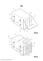
[0012] A Figura 3 é uma vista lateral de um conjunto com uma membrana colocada na pilha de placas bipolares;[0012] Figure 3 is a side view of an assembly with a membrane placed in the stack of bipolar plates;
[0013] A Figura 4 mostra um conjunto da invenção com um coletor e uma válvula de não retorno;[0013] Figure 4 shows an assembly of the invention with a collector and a non-return valve;
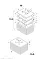
[0014] A Figura 5 ilustra uma placa separadora da invenção;[0014] Figure 5 illustrates a separator plate of the invention;
[0015] A Figura 6 ilustra outra configuração de um conjunto da invenção em que postes são moldados por injeção nos canais transversais;[0015] Figure 6 illustrates another configuration of an assembly of the invention in which posts are injection molded in the transverse channels;
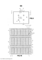
[0016] As Figuras 7 e 8 ilustram pilhas de placas de bateria e placas separadoras;[0016] Figures 7 and 8 illustrate stacks of battery plates and separator plates;
[0017] A Figura 9 mostra outra configuração de um conjunto da invenção;[0017] Figure 9 shows another configuration of a kit of the invention;
[0018] A Figura 10 mostra uma vista em corte do conjunto da Figura 9 por um par de canais transversais ao longo do plano A-A;[0018] Figure 10 shows a sectional view of the assembly of Figure 9 by a pair of transverse channels along the plane A-A;
[0019] A Figura 11 mostra uma vista parcial em corte da extremidade de uma pilha mostrando os furos de respiro ao longo da linha B-B;[0019] Figure 11 shows a partial sectional view of the end of a stack showing the vent holes along the line B-B;
[0020] A Figura 12 mostra uma vista em corte do conjunto da Figura 9 pelos furos de respiro até as células eletroquímicas ao longo do plano C-C;[0020] Figure 12 shows a sectional view of the assembly of Figure 9 through the vent holes to the electrochemical cells along the C-C plane;
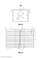
[0021] A Figura 13 mostra outra configuração de um conjunto da invenção com uma válvula na placa de extremidade do conjunto;[0021] Figure 13 shows another configuration of an assembly of the invention with a valve on the end plate of the assembly;
[0022] A Figura 14 mostra uma vista em corte do conjunto da Figura 13 por um canal integrado em comunicação com os furos de respiro para as células eletroquímicas ao longo do plano EE; e[0022] Figure 14 shows a sectional view of the assembly of Figure 13 by an integrated channel in communication with the vent holes for the electrochemical cells along the EE plane; and
[0023] A Figura 15 mostra uma vista em corte do conjunto da Figura 13 por um canal integrado em comunicação com os furos de respiro para as células eletroquímicas ao longo do plano DD.[0023] Figure 15 shows a sectional view of the assembly of Figure 13 by an integrated channel in communication with the vent holes for the electrochemical cells along the DD plane.
[0024] As ilustrações e explicações ora apresentadas pretendem ensinar aos demais técnicos no assunto a invenção, seus princípios e sua aplicação prática. Os técnicos no assunto podem adaptar e aplicar a invenção em suas várias formas, como possa ser melhor adequado aos requisitos de um determinado uso. Assim, as configurações específicas da presente invenção como indicadas não pretendem ser exaustivas ou limitarem da invenção. O escopo da invenção deve ser determinado em referência às reivindicações anexas, junto com o escopo completo dos equivalentes para os quais essas reivindicações se destinam. As revelações de todos os artigos e referências, incluindo pedidos e publicações de patentes, são incorporadas por referência para todas as finalidades.[0024] The illustrations and explanations presented here intend to teach other technicians in the subject the invention, its principles and its practical application. Those skilled in the art may adapt and apply the invention in its various forms, as may best suit the requirements of a particular use. Thus, the specific embodiments of the present invention as indicated are not intended to be exhaustive or limiting of the invention. The scope of the invention is to be determined by reference to the appended claims, together with the full scope of equivalents to which these claims are intended. The disclosures of all articles and references, including patent applications and publications, are incorporated by reference for all purposes.
[0025] A invenção refere-se a um artigo útil como bateria, compreendendo uma ou mais pilhas de uma pluralidade de placas bipolares, duas placas monopolares localizadas em cada extremidade da pilha de placas bipolares, tendo um eletrólito líquido colocado entre as placas bipolares; em que o artigo ainda compreende uma ou mais das seguintes características: 1) c) a uma ou mais pilhas de placas de bateria tendo uma pluralidade de canais que passam transversalmente pela parte das placas tendo o catodo e/ou o anodo nela depositados; e d) i) uma ou mais vedações na periferia dos canais que evitam o vazamento do eletrólito líquido nos canais, e postes localizados em um ou mais dos canais, tendo em cada extremidade uma parte superposta que cobre o canal e a superfície de vedação no exterior das placas monopolares adjacentes aos furos para os canais transversais e aplica pressão na superfície de vedação das placas monopolares em que a pressão é suficiente para suportar pressões criadas durante a montagem e a operação de células eletroquímicas criadas pelas pilhas de placas de bateria, ou ii) postes localizados em um ou mais canais tendo em cada extremidade uma parte que cobre o canal e uma superfície de vedação no exterior das placas monopolares adjacentes aos furos para os canais transversais e aplica pressão na superfície de vedação das placas monopolares, em que a pressão é suficiente para suportar pressões criadas durante a montagem e a operação das células eletroquímicas criadas pelas pilhas de placas de bateria, em que os postes são fabricados de um material que é capaz de suportar a exposição ao eletrólito e os postes evitam que o eletrólito entre nos canais; 2) c) uma membrana compreendendo um polímero termoplástico é colocada em toda a periferia das bordas das pilhas de placas de maneira a formar uma vedação na periferia da borda das placas, vedação que evita que o eletrólito flua para fora das pilhas de placas; 3) os separadores são sob a forma de placas tendo quadros aderidos em sua periferia, em que os quadros são adaptados para serem colocados adjacentes à periferia das placas do substrato de placas de bateria; e 4) c) uma válvula integrada e um canal integrado em comunicação com a válvula. Em algumas configurações, a membrana é formada por soldagem a quente de uma placa de material termoplástico na borda das placas. Em algumas configurações, a membrana é formada por moldagem de injeção nas placas. Os canais transversais podem ainda compreender vedações para evitar que o eletrólito líquido entre nos canais ou os postes possam ser escolhidos de maneira a também vedarem os canais para evitar que o eletrólito entre nos canais. A invenção se refere a um artigo útil como bateria, compreendendo uma pluralidade de placas bipolares tendo um eletrólito líquido colocado entre as placas bipolares e uma membrana compreendendo um polímero termoplástico que é colocada em toda a periferia da bordas das pilhas de placas, de maneira a formar uma vedação na periferia das pilhas de placas, vedação que evita que o eletrólito flua para fora das pilhas de placas. A membrana pode ser aplicada usando técnicas convencionais como a soldagem de uma membrana na borda da pilha de placas ou a moldagem da membrana nas pilhas de placas. A invenção compreende os processos descritos na presente para a preparação dos artigos ora revelados.[0025] The invention relates to an article useful as a battery, comprising one or more stacks of a plurality of bipolar plates, two monopolar plates located at each end of the stack of bipolar plates, having a liquid electrolyte placed between the bipolar plates; wherein the article further comprises one or more of the following features: 1) c) one or more stacks of battery plates having a plurality of channels passing transversely through the portion of the plates having the cathode and/or anode deposited thereon; and d) i) one or more seals on the periphery of the channels that prevent the leakage of liquid electrolyte into the channels, and posts located in one or more of the channels, having at each end an overlapping part that covers the channel and the sealing surface on the outside of the monopolar plates adjacent to the holes for the transverse channels and applies pressure to the sealing surface of the monopolar plates where the pressure is sufficient to withstand pressures created during the assembly and operation of electrochemical cells created by the battery plate stacks, or ii) posts located in one or more channels having at each end a part covering the channel and a sealing surface on the outside of the monopolar plates adjacent to the holes for the transverse channels and applying pressure to the sealing surface of the monopolar plates, where the pressure is sufficient to withstand pressures created during the assembly and operation of the electrochemical cells created by the battery plate stacks, wherein the posts are made of a material that is capable of withstanding exposure to electrolyte and the posts prevent electrolyte from entering the channels; 2) c) a membrane comprising a thermoplastic polymer is placed around the entire periphery of the edges of the plate stacks so as to form a seal at the periphery of the edge of the plates, which seal prevents electrolyte from flowing out of the plate stacks; 3) the spacers are in the form of plates having frames adhered to their periphery, wherein the frames are adapted to be placed adjacent the periphery of the plates of the battery plate substrate; and 4) c) an integrated valve and an integrated channel communicating with the valve. In some configurations, the membrane is formed by hot welding a plate of thermoplastic material to the edge of the plates. In some configurations, the membrane is formed by injection molding onto the plates. The transverse channels may further comprise seals to prevent liquid electrolyte from entering the channels or the posts may be chosen to also seal the channels to prevent electrolyte from entering the channels. The invention relates to an article useful as a battery, comprising a plurality of bipolar plates having a liquid electrolyte placed between the bipolar plates and a membrane comprising a thermoplastic polymer which is placed around the periphery of the edges of the plate stacks so as to form a seal on the periphery of the plate stacks, which seal prevents electrolyte from flowing out of the plate stacks. The membrane can be applied using conventional techniques such as welding a membrane to the edge of the plate stack or molding the membrane into the plate stacks. The invention comprises the processes described herein for the preparation of the articles disclosed herein.
[0026] Os artigos e processos da invenção podem ainda compreender um ou mais das características listadas abaixo em uma combinação, incluindo as preferências e configurações alternativas reveladas neste pedido: os substratos das placas monopolares e bipolares compreendem um polímero termoplástico; uma membrana compreendendo um polímero termoplástico é colocada em toda a periferia das pilhas de placas de maneira a formar uma vedação nas bordas das placas, vedação que evita que o eletrólito flua para fora das pilhas de placas; uma membrana é fundida nas bordas de todas as placas, de maneira a formar uma vedação na periferia das placas; uma membrana é moldada na pilha de placas; uma membrana é moldada por injeção nas pilhas de placas; a borda de ataque e a borda de fuga da membrana são fundidas entre si, para que a membrana forme uma vedação na periferia de uma ou mais pilhas de placas, de maneira que os eletrólitos não passem do interior da pilha para fora da membrana; o artigo compreende vedações na periferia dos canais transversais e as vedações compreendem uma ou mais membranas; o artigo compreende vedações na periferia dos canais transversais e as vedações são formadas por buchas localizadas entre os furos nas placas ao longo dos canais transversais; o artigo compreende vedações na periferia dos canais transversais e os postes compreendem qualquer material que tenha suficiente integridade estrutural para reter as partes superpostas no lugar, de maneira a aplicar pressão nas superfícies de vedação das placas monopolares; o artigo compreende vedações na periferia dos canais transversais e os postes compreendem qualquer metal que tenha suficiente integridade estrutural para reter as partes superpostas no lugar, de maneira a aplicar pressão às superfícies de vedação das placas monopolares; o artigo não compreende vedações na periferia dos canais transversais e os postes compreendem um material que mantém sua integridade estrutural quando exposto ao eletrólito, sendo não condutivo e que veda os canais transversais para evitar que o eletrólito entre nos canais; os postes compreendem uma cerâmica ou polímero que exibe uma transição para o vidro ou temperatura de fusão acima da temperatura de operação das células eletroquímicas formadas pelas pilhas de placas; os postes compreendem o rosqueamento no exterior dos postes, os canais são roscados para receberem os postes e os postes se adaptam nas roscas dos canais; a parte superposta é formada por porcas e as cabeças de parafusos na extremidade dos postes; os postes, incluindo a parte superposta, compreendem um ou mais polímeros termoplásticos e são formados por moldagem, como por moldagem de injeção; as buchas se localizam adjacentes a cada furo em cada placa de bateria de maneira que cada canal transversal seja vedado na pilha; as placas bipolares compreendem substratos poliméricos tendo uma pluralidade de aberturas passantes nos substratos, de maneira que cada abertura esteja em comunicação com ambas as faces do substrato, em que uma ou mais das aberturas são preenchidas com um material condutor que está em contato com ambas as faces dos substratos; o artigo ainda compreende uma válvula de não retorno adaptada para liberar a pressão na pilha vedada de placas bipolares quando a pressão atinge um nível de pressão predeterminado que esteja abaixo de uma pressão em que possam ocorrer danos ao artigo; os postes são moldados por injeção nos canais transversais; os substratos compreendem um polímero termoestável com uma fita de polímero termoplástico fixada na periferia dos substratos; em que a uma ou mais pilhas de placas de bateria tem e) um ou mais canais que passam transversalmente pela parte das placas tendo pastas de catodos e/ou anodos nela depositadas; e f) i) vedações na periferia dos canais que evitam o vazamento do líquido nos canais, e postes localizados em cada canal, cada um tendo em cada extremidade uma parte superposta que cobre o canal e as superfícies de vedação do exterior das placas monopolares que são adjacentes aos furos que passam transversalmente pelas placas e aplica pressão na superfície exterior das placas monopolares, em que a pressão é suficiente para suportar as pressões criadas durante a montagem e a operação das células criadas pelas pilhas de placas de bateria, ou ii) postes localizados em cada canal, cada um tendo em cada extremidade uma parte que cobre o canal e aplica pressão na superfície de vedação das placas monopolares que são adjacentes aos furos que passam transversalmente pelas placas, em que a pressão é suficiente para suportar as pressões criadas durante a montagem e a operação das células criadas pelas pilhas de placas de bateria, em que os postes são fabricados de um material que é capaz de suportar a exposição ao eletrólito e evita que o eletrólito entre nos canais; as vedações na periferia dos canais são formadas por moldagem de injeção; o separador tem uma superfície elevada em sua periferia adaptada para ser montada adjacente aos substratos das placas de bateria; o separador tem um ou mais furos passantes, em que os furos contêm insertos neles localizados, em que os insertos são adaptados para combinarem com os insertos nos furos das placas de bateria para formarem um canal na pilha de placas separadoras e de placas de bateria; os quadros dos separadores e os insertos são moldados nos separadores; os quadros dos separadores e os insertos são moldados por injeção; em que os quadros dos separadores e os insertos são moldados por injeção em uma peça; os substratos das placas de bateria têm superfícies levantadas em suas periferias adaptadas para serem montadas adjacente aos quadros aderidos aos separadores; em que as superfícies elevadas dos substratos e do quadro nos separadores são colocadas adjacentes entre si, de maneira que a periferia seja vedada contra um fluido que passe para dentro ou que saia do artigo; em que as placas de bateria e separadores tenham um ou mais furos passantes em que os furos se alinhem para formar um ou mais canais na pilha de placas de bateria e separadores; em que os furos nas placas de bateria e os separadores tenham insertos neles dispostos que formem um ou mais canais de vedação nas pilhas de placas de bateria e separadores; os insertos nas placas de bateria e nos separadores são formados por moldagem; em que os insertos nas placas de bateria e nos separadores são formados por moldagem de injeção; os canais de preenchimento ou de respiro são integrados na bateria e nas placas separadoras; e as válvulas são integradas nos canais de preenchimento ou de respiro.[0026] The articles and processes of the invention may further comprise one or more of the features listed below in a combination, including the preferences and alternative configurations disclosed in this application: the monopolar and bipolar plate substrates comprise a thermoplastic polymer; a membrane comprising a thermoplastic polymer is placed around the entire periphery of the plate stacks so as to form a seal at the edges of the plates, which seal prevents electrolyte from flowing out of the plate stacks; a membrane is fused at the edges of all the plates so as to form a seal at the periphery of the plates; a membrane is molded into the plate stack; a membrane is injection molded onto the plate stacks; the leading edge and trailing edge of the membrane are fused together so that the membrane forms a seal on the periphery of one or more plate stacks so that electrolytes do not pass from the inside of the stack to the outside of the membrane; the article comprises seals at the periphery of the transverse channels and the seals comprise one or more membranes; the article comprises seals on the periphery of the transverse channels and the seals are formed by bushings located between the holes in the plates along the transverse channels; the article comprises seals at the periphery of the transverse channels and the posts comprise any material that has sufficient structural integrity to retain the overlapping parts in place so as to apply pressure to the sealing surfaces of the monopolar plates; the article comprises seals at the periphery of the transverse channels and the posts comprise any metal that has sufficient structural integrity to retain the overlapping parts in place so as to apply pressure to the sealing surfaces of the monopolar plates; the article does not comprise seals on the periphery of the transverse channels and the posts comprise a material that maintains its structural integrity when exposed to the electrolyte, is non-conductive and which seals the transverse channels to prevent electrolyte from entering the channels; the posts comprise a ceramic or polymer that exhibits a glass transition or melting temperature above the operating temperature of the electrochemical cells formed by the plate stacks; the posts comprise threading on the outside of the posts, the channels are threaded to receive the posts and the posts fit into the threads of the channels; the overlapping part is formed by nuts and screw heads at the ends of the posts; the posts, including the overlapping part, comprise one or more thermoplastic polymers and are formed by molding, such as by injection molding; bushings are located adjacent to each hole in each battery plate so that each transverse channel is sealed in the battery; bipolar plates comprise polymeric substrates having a plurality of openings through the substrates such that each opening is in communication with both faces of the substrate, wherein one or more of the openings are filled with a conductive material which is in contact with both sides of the substrate. substrate faces; the article further comprises a non-return valve adapted to release pressure in the sealed stack of bipolar plates when the pressure reaches a predetermined pressure level which is below a pressure at which damage to the article may occur; the posts are injection molded in the transverse channels; the substrates comprise a thermosetting polymer with a thermoplastic polymer tape attached to the periphery of the substrates; wherein the one or more battery plate stacks has e) one or more channels passing transversely through the part of the plates having cathode and/or anode pastes deposited thereon; and f) i) seals on the periphery of the channels that prevent the leakage of liquid into the channels, and posts located in each channel, each having at each end a superposed part that covers the channel and the outer sealing surfaces of the monopolar plates that are adjacent to holes that pass transversely through the plates and apply pressure to the outer surface of the monopolar plates, where the pressure is sufficient to withstand the pressures created during assembly and operation of the cells created by the battery plate stacks, or ii) located posts in each channel, each having at each end a part that covers the channel and applies pressure to the sealing surface of the monopolar plates that are adjacent to the holes that pass transversely through the plates, where the pressure is sufficient to withstand the pressures created during the assembly and operation of the cells created by the battery plate stacks, wherein the posts are made of a material that is capable of supposing reduce exposure to electrolyte and prevent electrolyte from entering channels; the seals on the periphery of the channels are formed by injection molding; the separator has a raised surface on its periphery adapted to be mounted adjacent to the battery plate substrates; the separator has one or more through holes, wherein the holes contain inserts located therein, wherein the inserts are adapted to match the inserts in the holes in the battery plates to form a channel in the stack of separator plates and battery plates; separator frames and inserts are molded into the separators; separator frames and inserts are injection molded; wherein the separator frames and inserts are injection molded in one piece; the battery plate substrates have raised surfaces on their periphery adapted to be mounted adjacent to the frames adhered to the spacers; wherein the raised surfaces of the substrates and frame in the spacers are placed adjacent to each other so that the periphery is sealed against fluid passing into or out of the article; wherein the battery plates and spacers have one or more through holes wherein the holes align to form one or more channels in the stack of battery plates and spacers; wherein the holes in the battery plates and the separators have inserts disposed therein that form one or more sealing channels in the stacks of battery plates and separators; inserts in battery plates and separators are formed by molding; wherein the inserts in the battery plates and separators are formed by injection molding; fill or vent channels are integrated into the battery and separator plates; and the valves are integrated into the filling or vent channels.
[0027] Os artigos da invenção compreendem uma ou mais placas de eletrodos bipolares, preferencialmente uma pluralidade de placas bipolares. Pluralidade, como usada na presente, significa a existência de mais de uma das placas. A placa bipolar compreende um substrato com a forma de uma placa tendo duas faces opostas. Nas faces opostas localizam-se um catodo e um anodo. Em algumas configurações da invenção, as placas bipolares são dispostas nos artigos em pilhas em que o catodo de uma placa bipolar faceia o anodo da outra placa bipolar ou uma placa monopolar tendo um anodo e o anodo de cada placa bipolar faceia o catodo de uma placa bipolar ou monopolar. No artigo é formado um espaço entre os anodos e os catodos adjacentes, em que o espaço contém um eletrólito que funciona com o par de anodos e catodos para formar uma célula eletroquímica. A construção dos artigos resulta em células fechadas que são vedadas contra o ambiente para evitar vazamentos e curtos-circuitos das células. O número das placas presentes pode ser escolhido para prover a desejada tensão da bateria. O projeto da bateria bipolar dá flexibilidade na tensão que pode ser produzida. As placas bipolares podem ter qualquer forma de seção transversal e a forma de seção transversal pode ser projetada para se adaptar ao espaço de embalagem disponível no ambiente de uso. A forma de seção transversal se refere à forma das placas na perspectiva das faces da placas. Formas e tamanhos flexíveis de seção transversal permitem a preparação dos artigos da invenção de maneira a acomodarem a tensão e as dimensões necessárias para o sistema em que as baterias são utilizadas. As placas monopolares são dispostas nas extremidades das pilhas de placas para formarem as células de extremidade da pilha de placas. As placas monopolares podem ser preparadas a partir dos mesmos substratos e anodos e catodos utilizados como placas bipolares. O lado da placa monopolar oposto ao anodo ou ao catodo pode ser o substrato nu quando outro estojo for utilizado ou quando possa conter uma cobertura útil para a proteção da pilha. Em algumas configurações, as placas monopolares, podem ter um ou mais terminais passantes na placa a partir da célula de extremidade para o exterior. O terminal combina com a polaridade do anodo ou do catodo da placa monopolar. O terminal funciona para transmitir os elétrons gerados nas células eletroquímicas para o sistema que usa os eletros gerados sob a forma de eletricidade.[0027] The articles of the invention comprise one or more bipolar electrode plates, preferably a plurality of bipolar plates. Plurality, as used herein, means the existence of more than one of the plates. The bipolar plate comprises a substrate in the form of a plate having two opposing faces. On the opposite faces are located a cathode and an anode. In some embodiments of the invention, the bipolar plates are arranged in the articles in stacks wherein the cathode of one bipolar plate faces the anode of the other bipolar plate or a monopolar plate having an anode and the anode of each bipolar plate faces the cathode of one plate. bipolar or monopolar. In the article, a space is formed between the anodes and adjacent cathodes, in which the space contains an electrolyte that works with the pair of anodes and cathodes to form an electrochemical cell. The construction of the articles results in closed cells that are sealed against the environment to prevent cell leakage and short circuits. The number of plates present can be chosen to provide the desired battery voltage. The bipolar battery design gives flexibility in the voltage that can be produced. Bipolar boards can have any cross-sectional shape and the cross-sectional shape can be designed to fit the packaging space available in the usage environment. The cross-sectional shape refers to the shape of the plates from the perspective of the faces of the plates. Flexible cross-sectional shapes and sizes allow for the preparation of the articles of the invention to accommodate the voltage and dimensions required for the system in which the batteries are used. Monopolar plates are arranged at the ends of the plate stacks to form the end cells of the plate stack. Monopolar plates can be prepared from the same substrates and anodes and cathodes used as bipolar plates. The side of the monopolar plate opposite the anode or cathode may be the bare substrate when another case is used or when it may contain a useful cover for battery protection. In some configurations, single-pole boards may have one or more terminals passing through the board from the end cell to the outside. The lead matches the anode or cathode polarity of the monopolar plate. The terminal works to transmit the electrons generated in the electrochemical cells to the system that uses the generated electrons in the form of electricity.
[0028] O substrato funciona para dar suporte estrutural para o catodo e/ou o anodo; como uma partição de célula para evitar o fluxo do eletrólito entre células adjacentes; como cooperação com outros componentes da bateria para formar uma vedação contra eletrólitos nas bordas da placa bipolar, que pode ser na superfície externa da bateria; e em algumas configurações, para transmitir elétrons de uma superfície para outra. O substrato pode ser formado por uma variedade de materiais, dependendo da função da química da bateria. O substrato pode ser formado por materiais que sejam estruturalmente robustos o suficiente para prover o apoio de uma desejada placa de eletrodo bipolar, que suporte temperaturas que ultrapassem os pontos de fusão de qualquer dos materiais condutores utilizados na construção da bateria, e tendo alta estabilidade química durante o contato com um eletrólito (por exemplo, solução de ácido sulfúrico), de maneira que o substrato não se degrade no contato com o eletrólito. O substrato pode ser formado por materiais adequados e/ou configurado de forma a permitir a transmissão de eletricidade de uma superfície do substrato para uma superfície oposta do substrato. A placa do substrato pode ser formada por um material eletricamente condutor, por exemplo, um material metálico, ou pode ser formado por um material eletricamente não condutor. Os materiais eletricamente não condutores incluem polímeros; como polímeros termoestáveis, polímeros elastoméricos ou polímeros termoplásticos ou qualquer de suas combinações. Em algumas configurações, o substrato não condutor pode ter características eletricamente condutoras construídas em si ou sobre si. Os exemplos de materiais poliméricos que podem ser empregados incluem poliamida, poliéster, poliestireno, polietileno (incluindo polietileno tereftalato, polietileno de alta densidade e polietileno de baixa densidade), policarbonatos (PC) , polipropileno, cloreto de polivinila, plásticos biobaseados/biopolímeros (por exemplo, ácido polilático), silicone, acrilonitrila butadieno estireno (ABS), ou quaisquer de suas combinações, como PC/ABS (misturas de policarbonatos e acrilonitrila butadieno estirenos). Podem ser usados substratos compostos, o composto podendo conter materiais de reforço, como fibras ou cargas comumente conhecidas na técnica, dois diferentes materiais poliméricos, como um núcleo termoestável e um revestimento termoplástico ou borda termoplástica na periferia do polímero termoestável, ou material condutor disposto em um polímero não condutor. Na configuração preferida, o substrato compreende ou tem na borda das placas um material termoplástico que pode ser ligado, preferencialmente ligado por fusão. Em uma configuração, o substrato pode ter uma borda levantada na periferia, de maneira a facilitar o empilhamento das placas bipolares e a formação de células eletroquímicas. A borda levantada como utilizada neste contexto, significa borda levantada em pelo menos uma das duas superfícies opostas das placas. A borda levantada pode compreender uma parte de borda termoplástica formada sobre outro material substrato. A borda levantada pode funcionar como as placas separadoras descritas na presente. O substrato ou a periferia do substrato é preferencialmente compreendido por material não condutor, e preferencialmente por um material termoplástico. O quadro sobre ou integrado ao separador é preferencialmente compreendido por material não condutor, e preferencialmente por um material termoplástico. O uso de material não condutor amplia a vedação da parte externa da pilha da bateria.[0028] The substrate functions to provide structural support for the cathode and/or anode; as a cell partition to prevent electrolyte flow between adjacent cells; as cooperating with other battery components to form an electrolyte seal at the edges of the bipolar plate, which may be on the outside surface of the battery; and in some configurations, to transmit electrons from one surface to another. The substrate can be formed from a variety of materials, depending on the battery's chemistry function. The substrate can be formed of materials that are structurally robust enough to support a desired bipolar electrode plate, that withstand temperatures that exceed the melting points of any of the conductive materials used in battery construction, and have high chemical stability. during contact with an electrolyte (e.g. sulfuric acid solution), so that the substrate does not degrade on contact with the electrolyte. The substrate may be formed of suitable materials and/or configured to allow transmission of electricity from one surface of the substrate to an opposite surface of the substrate. The substrate plate may be formed from an electrically conductive material, for example a metallic material, or it may be formed from an electrically non-conductive material. Electrically non-conductive materials include polymers; as thermostable polymers, elastomeric polymers or thermoplastic polymers or any combination thereof. In some configurations, the non-conductive substrate may have electrically conductive features built into or on top of it. Examples of polymeric materials that may be employed include polyamide, polyester, polystyrene, polyethylene (including polyethylene terephthalate, high density polyethylene and low density polyethylene), polycarbonates (PC), polypropylene, polyvinyl chloride, biobased plastics/biopolymers (e.g. e.g. polylactic acid), silicone, acrylonitrile butadiene styrene (ABS), or any combination thereof, such as PC/ABS (blends of polycarbonates and acrylonitrile butadiene styrenes). Composite substrates may be used, the composite may contain reinforcing materials such as fibers or fillers commonly known in the art, two different polymeric materials such as a thermosetting core and a thermoplastic coating or thermoplastic edge on the periphery of the thermosetting polymer, or conductive material arranged in a non-conductive polymer. In the preferred embodiment, the substrate comprises or has at the edge of the plates a thermoplastic material which can be bonded, preferably melt bonded. In one configuration, the substrate may have a raised edge at the periphery to facilitate stacking of the bipolar plates and the formation of electrochemical cells. Raised edge as used in this context means raised edge on at least one of the two opposing surfaces of the boards. The raised edge may comprise a thermoplastic edge portion formed over another substrate material. The raised edge can function like the spacer plates described herein. The substrate or the periphery of the substrate is preferably comprised of non-conductive material, and preferably of a thermoplastic material. The frame on or integrated into the separator is preferably comprised of a non-conductive material, and preferably of a thermoplastic material. The use of non-conductive material increases the seal on the outside of the battery cell.
[0029] Em algumas configurações, o substrato compreende um geralmente substrato não eletricamente condutor (por exemplo, um substrato dielétrico) que inclui uma ou mais aberturas nele formadas. As aberturas podem ser usinadas (por exemplo, furadas), formadas durante a fabricação do substrato (por exemplo, por uma operação de moldagem ou formação), ou fabricadas de outra forma. O tamanho e a frequência das aberturas formadas no substrato podem afetar a resistividade da bateria. As aberturas podem ser formadas tendo um diâmetro de pelo menos cerca de 0,2 mm. As aberturas podem ser formadas tendo um diâmetro de cerca de 5 mm ou menos. As aberturas podem ser formadas tendo um diâmetro de cerca de 1,4 mm a cerca de 1,8 mm. As aberturas podem ser formadas tendo uma densidade de pelo menos cerca de 0,02 aberturas por cm2. As aberturas podem ser formadas tendo uma densidade de menos de cerca de 4 aberturas por cm2. As aberturas podem ser formadas tendo uma densidade de cerca de 2,0 aberturas por cm2 a cerca de 2,8 aberturas por cm2. As aberturas podem ser preenchidas com um material eletricamente condutor, por exemplo, um material contendo um metal. O material eletricamente condutor pode ser um material que se submeta a uma transformação de fase em uma temperatura que esteja abaixo da temperatura de degradação térmica do substrato, de maneira que em uma temperatura de operação do conjunto da bateria que esteja abaixo da temperatura de transformação de fase, o substrato dielétrico tenha um caminho eletricamente condutor pela mistura do material entre a primeira superfície e a segunda superfície do substrato. Além disso, na temperatura que esteja acima da temperatura de transformação de fase, a mistura do material eletricamente condutor passa por uma transformação de fase que desabilita a condutividade elétrica por meio do caminho eletricamente condutor. Por exemplo, o material eletricamente condutor pode ser ou incluir um material de solda, por exemplo, um compreendendo pelo menos um ou uma mistura de dois ou mais de chumbo estanho, níquel, zinco, lítio, antimônio, cobre, bismuto, índio ou prata. O material eletricamente condutor pode estar substancialmente isento de chumbo (isto é, contém no máximo traços de chumbo) ou pode incluir chumbo em uma quantidade funcionalmente operacional. O material pode incluir uma mistura de chumbo e estanho. Por exemplo, pode incluir uma grande parte de estanho e uma pequena parte de chumbo (por exemplo, cerca de 55 a cerca de 65 partes em peso de estanho e cerca de 35 a cerca de 45 partes em peso de chumbo) . O material pode exibir uma a temperatura de fusão que esteja abaixo de cerca de 240 °C, 230 °C, 220 °C, 210 °C ou mesmo abaixo de cerca de 200 °C (por exemplo, na faixa de cerca de 180 a cerca de 190 °C) . O material pode incluir uma mistura eutética. Uma característica do uso da solda como material eletricamente condutor para o preenchimento das aberturas é que a solda tem uma temperatura de fusão definida que pode ser dimensionada, dependendo do tipo de aranha utilizada, para fundir em uma temperatura que possa não ser segura para a operação continuada da bateria. Quando a solda funde, a abertura do substrato que contém a solda fundida não é mais eletricamente condutora, sendo criado um circuito aberto no interior da placa do eletrodo. Um circuito aberto pode operar para aumentar dramaticamente a resistência no interior da bateria bipolar, parando assim os novos fluxos elétricos e desligando as reações não seguras dentro da bateria. Assim, o tipo de material eletricamente condutor selecionado que preenche as aberturas pode variar, caso seja desejado incluir esse mecanismo de desligamento interno dentro da bateria, e sendo assim, em que temperatura é desejado efetuar esse desligamento interno. O substrato será configurado de maneira que na eventualidade de condições de operação que ultrapassarem uma condição predeterminada, o substrato funcionará para desabilitar a operação da bateria, interrompendo a condutividade elétrica no substrato. Por exemplo, o material eletricamente condutor que preenche os furos em um substrato dielétrico passa por uma transformação de fase (por exemplo, fundirá) de maneira que a condutividade elétrica no substrato seja interrompida. A extensão da interrupção pode ser para parcialmente ou mesmo totalmente desabilitar a função de condução de eletricidade no substrato.[0029] In some embodiments, the substrate generally comprises a non-electrically conductive substrate (eg, a dielectric substrate) that includes one or more apertures formed therein. The openings can be machined (eg, drilled), formed during substrate fabrication (eg, by a molding or forming operation), or otherwise fabricated. The size and frequency of openings formed in the substrate can affect battery resistivity. The openings may be formed having a diameter of at least about 0.2 mm. The openings can be formed having a diameter of about 5 mm or less. The openings can be formed having a diameter of from about 1.4 mm to about 1.8 mm. The apertures may be formed having a density of at least about 0.02 apertures per
[0030] Dispostos em uma superfície das placas bipolares e em algumas das placas monopolares há um ou mais catodos. O catodo ser de qualquer material que seja capaz de operar como um catodo em uma bateria e possa ter qualquer forma comumente usada nas baterias. O catodo é também denominado de material ativo positivo. O material ativo positivo pode compreender um óxido composto, um sulfato composto ou um fosfato composto de lítio, chumbo, carbono ou um metal de transição geralmente utilizado em um íon de lítio, níquel hidreto metálico ou bateria secundária de ácido-chumbo. Os exemplos dos óxidos compostos incluem óxido composto Li/Co como o óxido composto LiCoO2, Li/Ni, óxido composto LiNiO2, Li/Mn como o espinel LiMn2 O4, e os materiais compostos baseados em Li/Fe como o LiFeO2. Compostos exemplares de fosfato e enxofre de metal de transição e lítio incluem LiFePO4, V2O5, MnO2, TiS2, MoS2. MoO3, PbO2, AgO, NiOOH e similares. O material catodo pode ter qualquer forma que permita ao material catodo funcionar como um catodo em uma célula eletroquímica. As formas exemplares incluem partes formadas, em forma de pasta, placa ou filme pré-fabricado. Para baterias de chumbo-ácido, o material preferido dos catodos é o dióxido de chumbo (PbO2) . Colocado em uma superfície oposta das placas bipolares e da outra placa monopolar estão os anodos. Os anodos também são denominados de material ativo negativo. Qualquer anodo e material de anodo podem ser usados nos conjuntos da invenção. O material do anodo pode incluir qualquer material utilizado em baterias secundárias, incluindo baterias de chumbo-ácido, hidretos metálicos de níquel e de íons de lítio. Os materiais exemplares úteis para a construção dos anodos incluem chumbo, óxidos compostos de carbono ou lítio ou metal de transição, (como óxido composto de titânio ou de titânio e lítio) e similares. Um material preferido de anodo para chumbo-ácido é o chumbo esponja. O material do catodo pode ter qualquer forma que permita ao material do catodo funcionar como um catodo em uma célula eletroquímica. As formas exemplares incluem partes formadas, em forma de pasta, placas ou filmes pré-fabricados. As composições de pasta podem conter alguns aditivos benéficos, incluindo flocos ou fibras de vidro para reforço, vários compostos ligano-orgânicos para a estabilidade da pasta e aditivos condutores como o carbono, particularmente para os materiais ativos negativos. Para as baterias de chumbo-ácido, a forma preferida do material do anodo é o chumbo esponja. O anodo e o catodo são escolhidos para funcionarem juntos como uma célula eletroquímica quando o circuito formado incluir células.[0030] Arranged on a surface of the bipolar plates and on some of the monopolar plates are one or more cathodes. The cathode will be of any material that is capable of operating as a cathode in a battery and can be of any shape commonly used in batteries. The cathode is also called positive active material. The positive active material may comprise a composite oxide, a composite sulfate or a phosphate composite of lithium, lead, carbon or a transition metal commonly used in a lithium ion, nickel metal hydride or lead acid secondary battery. Examples of composite oxides include Li/Co composite oxide such as LiCoO2, Li/Ni composite oxide, LiNiO2, Li/Mn composite oxide such as LiMn2 O4 spinel, and Li/Fe based composite materials such as LiFeO2. Exemplary lithium transition metal phosphate and sulfur compounds include LiFePO4, V2O5, MnO2, TiS2, MoS2. MoO3, PbO2, AgO, NiOOH and the like. The cathode material can be of any shape that allows the cathode material to function as a cathode in an electrochemical cell. Exemplary shapes include formed parts, in the form of paste, plate or prefabricated film. For lead-acid batteries, the preferred cathode material is lead dioxide (PbO2 ). Placed on an opposite surface of the bipolar plates and the other monopolar plate are the anodes. Anodes are also called negative active material. Any anode and anode material can be used in the assemblies of the invention. The anode material can include any material used in secondary batteries, including lead-acid, nickel-metal hydride, and lithium-ion batteries. Exemplary materials useful for the construction of anodes include lead, oxides composed of carbon or lithium or transition metal, (such as oxide composed of titanium or titanium and lithium) and the like. A preferred anode material for lead acid is sponge lead. The cathode material can be of any shape that allows the cathode material to function as a cathode in an electrochemical cell. Exemplary shapes include formed parts, paste form, prefabricated sheets or films. The pulp compositions may contain some beneficial additives, including glass flakes or fibers for reinforcement, various binder-organic compounds for pulp stability, and conductive additives such as carbon, particularly for the negative active materials. For lead-acid batteries, the preferred form of anode material is sponge lead. The anode and cathode are chosen to work together as an electrochemical cell when the circuit formed includes cells.
[0031] Os conjuntos da invenção ainda compreendem separadores. Os separadores localizam-se entre o anodo e o catodo nas células eletroquímicas, mais especificamente os separadores localizam-se entre as placas bipolares ou entre a placa bipolar e uma placa monopolar. Os separadores preferencialmente têm uma área que é maior que a área do catodo e do anodo adjacentes. Preferencialmente, o separador separa completamente a parte do catodo da célula da parte do anodo da célula. As bordas do separador preferencialmente contatam as bordas periféricas das placas bipolares e monopolares que não tenham um anodo ou catodo nelas dispostos, de maneira a separar completamente a parte do anodo da célula da parte do catodo da célula. Um separador de bateria funciona para dividir as células eletroquímicas; para evitar os curtos-circuitos das células devido à formação de dendritos; funciona para permitir que o eletrólito líquido, os íons, os elétrons ou qualquer combinação desses elementos passe através. Qualquer separador conhecido de bateria que realize uma ou mais das funções mencionadas pode ser usado nos conjuntos da invenção. Preferencialmente, o separador é preparado a partir de um material não condutor, como filmes poliméricos porosos, mantas de vidro, borrachas porosas, géis ionicamente condutores ou materiais naturais, como madeira e similares. Preferencialmente, o separador contém poros ou caminhos tortuosos através do separador que permitem que os eletrólitos, íons, elétrons ou uma combinação desses passem pelo separador. Entre os materiais mais preferidos úteis como separadores estão as mantas de vidro absorvente, e membranas de poliolefinas porosas com peso molecular ultra-alto e similares.[0031] The assemblies of the invention further comprise spacers. The separators are located between the anode and the cathode in electrochemical cells, more specifically the separators are located between the bipolar plates or between the bipolar plate and a monopolar plate. The separators preferably have an area that is greater than the area of the adjacent cathode and anode. Preferably, the separator completely separates the cathode part of the cell from the anode part of the cell. The edges of the separator preferably contact the peripheral edges of bipolar and monopolar plates that do not have an anode or cathode disposed thereon, so as to completely separate the anode part of the cell from the cathode part of the cell. A battery splitter works to split electrochemical cells; to prevent cell short circuits due to the formation of dendrites; works to allow liquid electrolyte, ions, electrons, or any combination of these elements to pass through. Any known battery separator that performs one or more of the mentioned functions can be used in the kits of the invention. Preferably, the separator is prepared from a non-conductive material such as porous polymeric films, glass mats, porous rubbers, ionically conductive gels or natural materials such as wood and the like. Preferably, the separator contains pores or tortuous paths through the separator that allow electrolytes, ions, electrons or a combination thereof to pass through the separator. Among the most preferred materials useful as separators are absorbent glass mats, ultra-high molecular weight porous polyolefin membranes and the like.
[0032] Em algumas configurações, os artigos da invenção ainda compreendem placas ou folhas metálicas. As placas ou folhas metálicas funcionam para dispersar os elétrons que fluem na célula eletroquímica de maneira a garantir a conexão elétrica do material ativo com o substrato, e em algumas configurações, funcionarem como coletores de corrente. Em algumas configurações, as baterias contêm condutores de corrente que transmitem os elétrons para os terminais positivos da bateria, e nessas configurações as placas ou folhas metálicas conduzem os elétrons para o condutor de corrente. As placas ou folhas metálicas podem ser preparadas a partir de qualquer metal condutor, sendo os preferidos metais condutores a prata, o estanho, o cobre e o chumbo. A seleção do metal é influenciada pelos materiais do anodo e do catodo. Em uma bateria chumbo-ácido, são preferidas as placas ou as folhas de chumbo. As folhas ou placas metálicas estão preferencialmente localizadas entre o anodo ou catodo e o substrato. As placas ou folhas metálicas podem ser fixadas ao substrato. Qualquer método para a fixação da placa ou da folha metálica ao substrato que retenha a folha ou placa metálica ao substrato no ambiente das células pode ser utilizado, como solda ou ligação adesiva. Preferencialmente as placas ou folhas metálicas são ligadas de forma adesiva ao substrato. Os adesivos preferidos e úteis para essa ligação incluem os epóxis, cimentos de borracha, resinas fenólicas, compostos de borracha nitrílica ou colas de cianoacrilato. Preferencialmente as placas ou folhas metálicas localizam-se entre toda a superfície do anodo ou do catodo e o substrato. As folhas e placas metálicas podem cobrir toda a superfície dos substratos. Na configuração em que o anodo ou catodo está sob a forma de pasta, a pasta é aplicada à folha ou a placa metálica. A folha ou placa metálica pode ter contator com um ou mais condutores de corrente para transmitir os elétrons aos condutores de corrente. As folhas e as placas metálicas são escolhidas tendo suficiente espessura para dispersar os elétrons que fluem pelas células e, onde adequado, para coletar elétrons e transmiti-los para os condutores de corrente na célula. Preferencialmente, as placas ou folhas metálicas têm uma espessura de cerca de 0,75 mm ou menos, mais preferencialmente cerca de 0,2 mm ou menos e mais preferencialmente cerca de 0,1 mm ou menos. Preferencialmente, as placas ou folhas metálicas têm espessura de cerca de 0,025 mm ou mais, mais preferencialmente cerca de 0,050 mm ou mais e mais preferencialmente cerca de 0,075 mm ou mais.[0032] In some embodiments, the articles of the invention further comprise metal plates or sheets. The metallic plates or sheets work to disperse the electrons that flow in the electrochemical cell in order to guarantee the electrical connection of the active material with the substrate, and in some configurations, work as current collectors. In some configurations, batteries contain current conductors that transmit electrons to the positive terminals of the battery, and in these configurations the metal plates or sheets conduct electrons to the current conductor. The metal plates or sheets can be prepared from any conductive metal, with silver, tin, copper and lead being preferred. Metal selection is influenced by anode and cathode materials. In a lead-acid battery, lead plates or sheets are preferred. The metal sheets or plates are preferably located between the anode or cathode and the substrate. The metal plates or sheets can be fixed to the substrate. Any method for attaching the foil or plate to the substrate that retains the foil or foil to the substrate in the cell environment can be used, such as soldering or adhesive bonding. Preferably the metal plates or sheets are adhesively bonded to the substrate. Preferred adhesives useful for such bonding include epoxies, rubber cements, phenolic resins, nitrile rubber compounds or cyanoacrylate glues. Preferably the metal plates or sheets are located between the entire surface of the anode or cathode and the substrate. Metal sheets and plates can cover the entire surface of substrates. In the configuration where the anode or cathode is in the form of a paste, the paste is applied to the sheet or metal plate. The foil or metal plate may have a contactor with one or more current conductors to transmit the electrons to the current conductors. Metal sheets and plates are chosen thick enough to disperse electrons flowing through the cells and, where appropriate, to collect electrons and transmit them to current conductors in the cell. Preferably, the metal plates or sheets have a thickness of about 0.75 mm or less, more preferably about 0.2 mm or less, and most preferably about 0.1 mm or less. Preferably, the metal plates or sheets have a thickness of about 0.025 mm or more, more preferably about 0.050 mm or more and most preferably about 0.075 mm or more.
[0033] A pilha de componentes no conjunto da invenção pode conter canais transversais que passam pelos componentes e a área formada para as células eletroquímicas, células que também contêm um eletrólito líquido. A pilha inclui placas bipolares, placas monopolares, separadores, anodos, catodos, opcionalmente placas metálicas e todos os demais componentes da pilha que possam ser utilizados. Os canais transversais funcionam para abrigar os postes e alguns dos canais podem ser deixados não preenchidos, de maneira a funcionarem como canais de resfriamento transverso ou canais de respiro/preenchimento. Em algumas configurações da invenção, os canais passam pelo anodo, catodo e a célula que contém o eletrólito. Os canais são vedados para evitar os eletrólitos e gases que saem durante a operação entre nos canais. Qualquer método de vedação que consiga este objetivo pode ser utilizado. O tamanho e a forma dos canais podem ter qualquer tamanho ou forma que os permita abrigar os postes e os postes para suportar a placa de extremidade e as bordas dos substratos e evitar o vazamento dos eletrólitos e gases que saem durante a operação e evitar as forças de compressão que surgem durante a operação dos componentes danificados e a vedação para as células eletroquímicas individuais. A forma pode preferencialmente ser redonda, elíptica ou poligonal, como quadrada, retangular, hexagonal e similares. O tamanho dos canais é escolhido para acomodar os postes utilizados. Os canais como uma material prática, compreendem uma série de furos nos componentes dispostos, de maneira que um poste pode ser colocado no canal formado ou de maneira que um fluido possa ser transmitido pelo canal para resfriamento. O número de canais é escolhido para suportar a placa de extremidade e as bordas dos substratos e evitar o vazamento dos eletrólitos e gases que saem durante a operação e para evitar as forças de compressão que surgem da operação contra os componentes de danificação e a vedação para as células eletroquímicas individuais. Preferencialmente, a pluralidade de canais está presente de maneira a difundir as forças de compressão geradas durante a operação. O número e o projeto dos canais são suficientes para minimizar as forças de estresse de borda que ultrapassam a resistência de fadiga das vedações. Os locais dos canais são escolhidos de maneira a dispersar as forças de compressão geradas durante a operação. É preferível dispersar os canais de alguma forma similar na pilha para melhor administrar os esforços. Preferencialmente os canais têm dimensão de seção transversal de cerca de 2 mm ou maior, mais preferencialmente cerca de 4 mm ou maior e mais preferencialmente cerca de 6 mm ou maior. O limite superior da dimensão da seção transversal dos canais é o prático, se o tamanho for muito grande, a eficiência dos conjuntos é reduzida. Preferencialmente os canais têm uma dimensão da seção transversal de cerca de 12 min ou menos e mais preferencialmente cerca de 10 mm ou menos.[0033] The stack of components in the assembly of the invention may contain transverse channels that pass through the components and the area formed for the electrochemical cells, cells that also contain a liquid electrolyte. The battery includes bipolar plates, monopolar plates, separators, anodes, cathodes, optionally metallic plates and all other components of the battery that can be used. The transverse channels function to house the posts and some of the channels can be left unfilled in order to function as transverse cooling channels or vent/fill channels. In some embodiments of the invention, the channels pass through the anode, cathode and the cell containing the electrolyte. The channels are sealed to prevent electrolytes and gases that escape during operation from entering the channels. Any sealing method that achieves this objective can be used. The size and shape of the channels can be any size or shape that allows them to house the posts and posts to support the end plate and the edges of the substrates and prevent leakage of electrolytes and gases that come out during operation and prevent the forces compression pressures that arise during operation of damaged components and sealing for individual electrochemical cells. The shape may preferably be round, elliptical or polygonal, such as square, rectangular, hexagonal and the like. The size of the channels is chosen to accommodate the posts used. The channels as a practical material comprise a series of holes in the components arranged so that a post can be placed in the formed channel or so that a fluid can be transmitted through the channel for cooling. The number of channels is chosen to support the end plate and edges of the substrates and to prevent leakage of electrolytes and gases leaving during operation and to avoid the compressive forces that arise from operation against damaging components and the seal to the individual electrochemical cells. Preferably, the plurality of channels is present in order to diffuse the compressive forces generated during operation. The number and design of the channels are sufficient to minimize edge stress forces that overcome the fatigue strength of the seals. Channel locations are chosen so as to disperse the compressive forces generated during operation. It is preferable to disperse the channels in some similar way in the stack to better manage the efforts. Preferably the channels have a cross-sectional dimension of about 2 mm or greater, more preferably about 4 mm or greater, and most preferably about 6 mm or greater. The upper limit of the dimension of the cross section of the channels is the practical one, if the size is too large, the efficiency of the sets is reduced. Preferably the channels have a cross-sectional dimension of about 12 min or less and more preferably about 10 mm or less.
[0034] Localizados em pelo menos alguns dos canais existem postes que realizam uma ou mais das seguintes funções: manter unida a pilha de componentes de maneira que os danos aos componentes ou o rompimento da vedação entre as bordas dos componentes da pilha seja evitado, garantir a compressão uniforme no material do separador, e garantir a espessura uniforme do material do separador. Preferencialmente os postes têm em cada extremidade uma parte superposta que se acopla à superfície externa das placas monopolares de extremidade. Esta parte superposta opera para aplicar pressão na superfície externa das placas monopolares de extremidade de maneira a evitar danos aos componentes ou o rompimento da vedação entre as bordas dos componentes da pilha, e evitar o abaulamento ou outros deslocamentos da pilha durante a operação da bateria. A parte superposta está em contato com uma superfície de vedação, a parte da placa de extremidade em contato com a parte superposta. Em algumas configurações, a pilha pode ter uma peça de extremidade separada estrutural ou de proteção na placa monopolar de extremidade e a parte superposta estará em contato com a superfície externa da peça de extremidade estrutural ou de proteção. A parte superposta pode ser qualquer estrutura que em conjunto com o poste evite danos aos componentes ou o rompimento da vedação entre as bordas dos componentes da pilha. Partes superpostas exemplares incluem cabeças de parafusos, porcas, cabeças moldadas, cavilhas, pinos de ajuste, colares de eixos e similares. Os postes têm um comprimento para poderem passar por toda a pilha e esse comprimento varia com base na capacidade desejada da bateria. Os postes preferencialmente demonstram uma forma e tamanho de seção transversal para preencher o canal. O número de postes é escolhido para suportar a placa de extremidade e as bordas dos substratos para evitar o vazamento dos eletrólitos e dos gases que saem durante a operação e para evitar as forças de compressão que surgem a operação contra os componentes de danificação e a vedação para as células eletroquímicas individuais, e para minimizar as forças de estresse de borda que ultrapassam a resistência à fadiga das vedações. Preferencialmente, existe uma pluralidade de postes de maneira a dispersar as forças de compressão geradas durante a operação. Pode haver menos postes que canais onde um ou mais dos canais forem usados como canais de resfriamento ou canais para preenchimento de respiro. Os postes podem compreender qualquer material que realize as funções necessárias. Se o poste for usado para vedar os canais, então o material utilizado é selecionado para suportar as condições de operação das células, e não será corroído quando exposto ao eletrólito e pode suportar as temperaturas e pressões geradas durante a operação das células. Quando os postes realizam a função de vedação, os postes preferencialmente compreendem um material polimérico ou cerâmico que possa suportar as condições mencionadas. Nesta configuração, o material deve ser não condutor para evitar o curto-circuito das células. Preferencialmente, os postes compreendem um material termoplástico como descrito na presente. Os materiais termoplásticos preferidos são o ABS, o polipropileno, o poliéster, poliuretanos termoplásticos, poliolefinas, resinas termoplásticas compostas, policarbonatos e similares. O ABS é o mais preferido. Onde os canais forem vedados separadamente, os postes podem compreender qualquer material que tenha a integridade estrutural para realizar as funções desejadas. Podem ser utilizados os materiais poliméricos mencionados acima, cerâmicas e metais. Os metais adequados podem ser o aço, latão alumínio, cobre e similares. Os postes podem compreender postes moldados, postes roscados ou postes com um ou mais fixações de extremidade. Quando as peças forem roscadas, as peças estruturais da pilha são roscadas para receberem os postes roscados. Os postes podem ter um cabeçote em uma extremidade e uma porca, furo para uma cavilha ou contrapino na outra ou pode ter uma porca, furo para uma cavilha ou contrapino em ambas as extremidades. Este é geralmente o caso para postes não moldados. Os postes podem ser construídos dessa forma de maneira a ser um dispositivo de catraca de uma via que permita o encurtamento, mas não a ampliação. Esse poste seria colocado no lugar, e depois como a pilha é comprimida, o poste é encurtado, de maneira que mantenha a pressão na pilha. O poste nesta configuração pode ter entalhes que facilitem a catraca, de maneira a permitir que os postes funcionem como uma parte de uma estrutura de ligação rápida. Podem ser usadas porcas e/ou arruelas de encaixe com os postes, de maneira a comprimirem as placas que estiverem adjacentes quando no lugar. As porcas e/ou arruelas que seguirem uma direção nos postes e entalhes podem estar presentes para evitar que as porcas e/ou arruelas se movam em outra direção ao longo dos postes. Em uso, os furos nos postes terão as cavilhas, os contrapinos adequados e similares para realizarem a função mencionada. Se o poste for moldado, poderá ser moldado separadamente ou no lugar. Se moldado no lugar, no local, a vedação deve estar presente no canal para reter o plástico fundido no lugar. Pode ser usado um poste não condutor que é roscado e que pode prover a necessária vedação. Alternativamente, um poste polimérico pré-moldado não condutor pode ser projetado para formar um ajuste de interferência no canal de forma a vedar os canais. Os postes podem ser formados no lugar por moldagem, como por moldagem de injeção.[0034] Located in at least some of the channels are posts that perform one or more of the following functions: holding the stack of components together so that damage to components or breaking the seal between the edges of the stack components is avoided, ensuring uniform compression in the separator material, and ensure the uniform thickness of the separator material. Preferably, the posts have at each end a superposed part which couples to the outer surface of the monopolar end plates. This overlapping part operates to apply pressure to the outer surface of the single-pole end plates in order to prevent damage to the components or rupture of the seal between the edges of the stack components, and to prevent bulging or other displacement of the stack during battery operation. The lap part is in contact with a sealing surface, the end plate part in contact with the lap part. In some configurations, the stack may have a separate structural or protective end piece on the monopolar end plate and the overlapping portion will be in contact with the outer surface of the protective or structural end piece. The overlapping part can be any structure that, together with the post, prevents damage to the components or the rupture of the seal between the edges of the components of the pile. Exemplary overlapping parts include screw heads, nuts, molded heads, dowels, adjustment pins, shaft collars and the like. The posts are long enough to run through the entire stack, and that length varies based on the desired battery capacity. The posts preferably demonstrate a cross-sectional shape and size to fill the channel. The number of posts is chosen to support the end plate and the edges of the substrates to prevent leakage of electrolytes and gases leaving during operation and to avoid the compressive forces that arise from operation against damaging components and the seal. for the individual electrochemical cells, and to minimize edge stress forces that overcome the fatigue strength of the seals. Preferably, there is a plurality of posts in order to disperse the compressive forces generated during operation. There may be fewer posts than channels where one or more of the channels are used as cooling channels or vent fill channels. The posts can comprise any material that performs the necessary functions. If the post is used to seal the channels, then the material used is selected to withstand the operating conditions of the cells, and will not corrode when exposed to the electrolyte and can withstand the temperatures and pressures generated during the cell's operation. When the posts perform the sealing function, the posts preferably comprise a polymeric or ceramic material that can withstand the mentioned conditions. In this configuration, the material must be non-conductive to avoid short circuiting the cells. Preferably, the posts comprise a thermoplastic material as described herein. Preferred thermoplastic materials are ABS, polypropylene, polyester, thermoplastic polyurethanes, polyolefins, composite thermoplastic resins, polycarbonates and the like. ABS is most preferred. Where the channels are sealed separately, the posts may comprise any material that has the structural integrity to perform the desired functions. The above mentioned polymeric materials, ceramics and metals can be used. Suitable metals may be steel, aluminum brass, copper and the like. The posts may comprise molded posts, threaded posts or posts with one or more end attachments. When the parts are threaded, the structural parts of the stack are threaded to receive the threaded posts. The posts may have a head at one end and a nut, hole for a dowel or cotter pin at the other, or they may have a nut, hole for a dowel or cotter pin at both ends. This is generally the case for unmolded posts. The posts can be constructed in this way to be a one-way ratchet device that allows for shortening but not widening. That post would be put in place, and then as the pile is compressed, the post is shortened so that it maintains pressure on the pile. The post in this configuration may have notches to facilitate the ratchet, so as to allow the posts to function as a part of a quick-connect structure. Lock nuts and/or washers may be used with the posts to compress adjacent boards when in place. Nuts and/or washers that run in one direction on the posts and notches may be present to prevent the nuts and/or washers from moving in the other direction along the posts. In use, the holes in the posts will have the appropriate dowels, cotter pins and the like to perform the mentioned function. If the pole is molded, it can be molded separately or in place. If molded in place, the seal must be present in the channel to hold the molten plastic in place. A non-conductive post which is threaded and which can provide the necessary seal may be used. Alternatively, a non-conductive precast polymeric post can be designed to form an interference fit in the channel to seal the channels. The posts can be formed in place by molding, such as by injection molding.
[0035] Quando montada a pilha de componentes, incluindo as placas monopolares e bipolares, formam células eletroquímicas vedadas. Localizado nas células vedadas há um eletrólito líquido. O eletrólito pode ser qualquer eletrólito líquido que facilite uma reação eletroquímica com o anodo e catodo utilizados. O eletrólito permite que os elétrons e íons fluam entre o anodo e catodo. Os eletrólitos podem ser baseados em água ou ter base orgânica. Os eletrólitos com base orgânica úteis na presente compreendem sais eletrólitos dissolvidos em um solvente orgânico. Nas baterias secundárias de íon de lítio, é necessário que o lítio esteja contido no sal eletrólito. Como sal eletrólito contendo lítio, por exemplo, podem ser usados LiPF6, LiClO4, LiBF4, LiAsFe, LiSO3CF3 e LiN(CF3SO2)2. Esses sais eletrólitos podem ser utilizados individualmente ou em combinação de dois ou mais. O solvente orgânico deve ser compatível com o separador, catodo e anodo e o sal eletrólito. É preferível usar um solvente orgânico que não se decomponha, mesmo quando for aplicada alta tensão ao mesmo. Por exemplo, é preferível usar carbonatos como o carbonato de etileno (EC), carbonato de propileno (PG), carbonato de butileno, dimetil carbonato (DMC), dietil carbonato e etil metil carbonato; éteres cíclicos como o tetrahidrofurano (THF) e 2- metiltetrahidrofurano; ésteres cíclicos como o 1,3-dioxolano e 4-metildioxolano; lactonas como a Y-butirolactona; sulfolano; 3-metilsulfolano; dimetoxietano, dietoxietano, etoximetoximetano e etildiglimo. Esses solventes podem ser utilizados individualmente ou em combinação de dois ou mais. A concentração do eletrólito no eletrólito líquido deve preferencialmente ser 0,3 a 5 mol/l. Normalmente, o eletrólito mostra a maior condutividade nas vizinhanças de 1 mol/l. O eletrólito líquido deve preferencialmente ter 30 a 70 por cento em peso e especialmente 40 a 60 por cento em peso do eletrólito. Os eletrólitos aquosos compreendem ácidos ou sais em água que ampliam o funcionamento da célula. Os sais e ácidos preferidos incluem o ácido sulfúrico, o sulfato de sódio ou os sais de potássio. O sal ou ácido está presente em quantidade suficiente para facilitar a operação da célula. Preferencialmente, a concentração é cerca de 0,5 por cento em peso do maior com base no peso do eletrólito, mais preferencialmente cerca de 1,0 ou maior e mais preferencialmente cerca de 1,5 por cento em peso ou maior. O eletrólito preferido em uma bateria chumbo- ácido é o ácido sulfúrico em água.[0035] When assembled the stack of components, including the monopolar and bipolar plates, form sealed electrochemical cells. Located in the sealed cells is a liquid electrolyte. The electrolyte can be any liquid electrolyte that facilitates an electrochemical reaction with the anode and cathode used. The electrolyte allows electrons and ions to flow between the anode and cathode. Electrolytes can be water based or organic based. Organic based electrolytes useful herein comprise electrolyte salts dissolved in an organic solvent. In lithium-ion secondary batteries, lithium is required to be contained in the electrolyte salt. As the lithium-containing electrolyte salt, for example, LiPF6, LiClO4, LiBF4, LiAsFe, LiSO3CF3 and LiN(CF3SO2)2 can be used. These electrolyte salts may be used singly or in combination of two or more. The organic solvent must be compatible with the separator, cathode and anode and the salt electrolyte. It is preferable to use an organic solvent that does not decompose, even when high voltage is applied to it. For example, it is preferable to use carbonates such as ethylene carbonate (EC), propylene carbonate (PG), butylene carbonate, dimethyl carbonate (DMC), diethyl carbonate and ethyl methyl carbonate; cyclic ethers such as tetrahydrofuran (THF) and 2-methyltetrahydrofuran; cyclic esters such as 1,3-dioxolane and 4-methyldioxolane; lactones such as Y-butyrolactone; sulfolane; 3-methylsulfolane; dimethoxyethane, diethoxyethane, ethoxymethoxymethane and ethyldiglyme. These solvents may be used singly or in combination of two or more. The concentration of the electrolyte in the liquid electrolyte should preferably be 0.3 to 5 mol/l. Typically, the electrolyte shows the highest conductivity in the vicinity of 1 mol/l. The liquid electrolyte should preferably contain 30 to 70 weight percent and especially 40 to 60 weight percent electrolyte. Aqueous electrolytes comprise acids or salts in water that enhance cell function. Preferred salts and acids include sulfuric acid, sodium sulfate or potassium salts. The salt or acid is present in sufficient quantity to facilitate cell operation. Preferably, the concentration is about 0.5 weight percent of the greater based on the weight of the electrolyte, more preferably about 1.0 or greater, and most preferably about 1.5 weight percent or greater. The preferred electrolyte in a lead-acid battery is sulfuric acid in water.
[0036] Os artigos da invenção podem compreender uma vedação entre os canais transversais e o poste. A vedação pode localizar-se no canal, no exterior do canal ou ambos. A vedação pode compreender qualquer material ou forma que evite que o eletrólito e os gases desenvolvidos durante a operação vazem das células eletroquímicas. A vedação pode ser uma membrana, luva ou uma série de insertos combinados ou bossas nas placas e/ou separadores ou inseridas no canal. A membrana pode ser elastomérica. O canal pode ser formado por uma série de insertos ou bossas, inseridos ou integrados nas placas e/ou separadores. Os insertos podem ser compressíveis ou capazes de se intertravarem para formarem uma vedação à prova de vazamento ao longo do canal. Os insertos podem ser formados no lugar nas placas de bateria e/ou separadores, como por moldagem no lugar. Preferencialmente os insertos são moldados no lugar por moldagem de injeção. A luva pode ser preparada com qualquer material que possa suportar a exposição ao eletrólito, as condições de operação das células eletroquímicas e forças exercidas pela inserção do poste ou pelo poste no canal. Os materiais poliméricos preferidos são aqueles descritos como úteis para os postes e os substratos. Em outra configuração, a vedação é formada por luvas ou buchas colocadas entre as placas monopolares e bipolares. As luvas podem ser relativamente rígidas e as buchas geralmente serão elastoméricas. As luvas e\ou buchas podem ser adaptadas para ajuste dentro de endentações nas placas monopolares e bipolares ou para terem extremidades que se insiram nos furos das placas, criando os canais transversais. As placas monopolares e bipolares podem ser formadas ou usinadas para conter endentações de combinação para as luvas e/ou as buchas. A montagem da pilha de placas com as luvas ou buchas pode criar ajustes de interferência para efetivamente vedar os canais. Alternativamente, as luvas ou buchas podem ser ligadas por fusão ou ligadas de forma adesiva às placas, de maneira a formarem uma vedação na união. Alternativamente, as luvas podem ser revestidas no interior com um revestimento que funciona para vedar o canal. Como acima mencionado, os postes podem funcionar para vedar os canais. É contemplado que uma combinação dessas soluções de vedação pode ser usada em um único canal ou em diferentes canais. Os componentes da pilha de placas, incluindo placas monopolares e placas bipolares, preferencialmente têm a mesma forma e bordas comuns. Isto facilita a vedação das bordas. Quando existirem separadores, estes geralmente têm uma estrutura similar à das placas de bateria para acomodarem a formação ou a criação dos canais transversais. Em outra configuração, a vedação pode ser um polímero termoestável, como um epóxi, poliuretano ou polímero acrílico injetado entre o parafuso e o canal transversal. A superfície de vedação da placa pode ser modificada para melhorar a vedação quando for aplicada a compressão pelos postes. A superfície de vedação pode ser alisada, contornada, tornada rugosa ou tratada superficialmente. Uma superfície alisada terá uma grande área de contator, com a qual é feita uma vedação estanque ao eletrólito sem os defeitos que permitem o fluxo do líquido. Contornos como anéis concêntricos, entalhes ou ondulações provocam áreas ou "anéis" de contato de alta pressão para resistir ao fluxo do eletrólito líquido. O entalhe pode ser preenchido com um material de gaxeta como uma placa plana deformável ou o-ring para facilitar a vedação do líquido. Superfícies de vedação rugosas de um material deformável podem comprimir e formar vedações confiáveis para o eletrólito líquido. O tratamento superficial da superfície de vedação para torna-la incompatível com o umedecimento do eletrólito líquido evitará que o eletrólito líquido flua para o canal. Se for usado um eletrólito hidrofílico, a superfície de vedação pode ser hidrofóbica. Da mesma forma, caso seja usado um eletrólito hidrofóbico, a superfície de vedação deve ser hidrofílica.[0036] The articles of the invention may comprise a seal between the transverse channels and the post. The seal may be located in the channel, outside the channel or both. The seal may comprise any material or shape that prevents electrolyte and gases developed during operation from leaking out of the electrochemical cells. The seal may be a membrane, sleeve or a series of matched inserts or bosses on the plates and/or spacers or inserted into the channel. The membrane may be elastomeric. The channel can be formed by a series of inserts or bosses, inserted or integrated in the plates and/or separators. Inserts may be compressible or capable of interlocking to form a leak-proof seal along the channel. Inserts can be formed in place on battery plates and/or spacers, such as by molding in place. Preferably the inserts are molded in place by injection molding. The glove can be prepared with any material that can withstand exposure to the electrolyte, the operating conditions of the electrochemical cells, and the forces exerted by the post insertion or the post in the channel. Preferred polymeric materials are those described as useful for posts and substrates. In another configuration, the seal is formed by sleeves or bushings placed between the monopolar and bipolar plates. Sleeves can be relatively rigid and bushings will generally be elastomeric. The sleeves and/or bushings can be adapted to fit within the indentations in the monopolar and bipolar plates or to have ends that insert into the holes of the plates, creating the transverse channels. Monopolar and bipolar plates can be formed or machined to contain combination indentations for the sleeves and/or bushings. Mounting the plate stack with the sleeves or bushings can create interference fits to effectively seal the channels. Alternatively, the sleeves or bushings may be fusion bonded or adhesively bonded to the plates to form a seal at the joint. Alternatively, the gloves can be coated on the inside with a coating that functions to seal the channel. As mentioned above, posts can function to seal off channels. It is contemplated that a combination of these sealing solutions may be used in a single channel or in different channels. Board stack components, including single-pole boards and double-pole boards, preferably have the same common shape and edges. This makes sealing the edges easier. When separators exist, they generally have a structure similar to that of battery plates to accommodate the formation or creation of transverse channels. In another configuration, the seal may be a thermosetting polymer such as an epoxy, polyurethane or acrylic polymer injected between the screw and the cross channel. The sealing surface of the board can be modified to improve sealing when compression is applied by the posts. The sealing surface can be smoothed, contoured, roughened or surface treated. A smooth surface will have a large contactor area, with which an electrolyte-tight seal is made without the defects that allow liquid to flow. Contours such as concentric rings, notches, or dimples cause high pressure contact areas or "rings" to resist the flow of liquid electrolyte. The notch can be filled with a gasket material such as a flat deformable plate or o-ring to facilitate liquid sealing. Rough sealing surfaces of a deformable material can compress and form reliable seals for the liquid electrolyte. Surface treatment of the sealing surface to make it incompatible with wetting the liquid electrolyte will prevent the liquid electrolyte from flowing into the channel. If a hydrophilic electrolyte is used, the sealing surface may be hydrophobic. Likewise, if a hydrophobic electrolyte is used, the sealing surface must be hydrophilic.
[0037] As bordas são vedadas para evitar o vazamento do eletrólito e dos gases produzidos nas células e isolar as células individuais para evitar o curto-circuito das células. As bordas podem ser vedadas usando qualquer método para a vedação de baterias. Em algumas configurações, as bordas do conjunto são vedadas usando os sistemas de vedação endo ou exoesqueleto revelados no pedido de patente de propriedade comum, Shaffer, II et. al., Conjunto de Bateria Bipolar, da patente norte-americana 23010/0183920 A1 incorporada à presente em sua totalidade por referência. O sistema de vedação revelado em Shaffer, II et al. contempla estruturas exclusivas para uma estrutura de bateria bipolar, como as estruturas acima descritas. As estruturas, caso provenientes dos métodos acima ou não, geralmente compreendem um primeiro quadro separador; um membro negativo de quadro de cola tendo uma ou mais bordas e uma estrutura de grade suporte que se prolonga entre a uma ou mais bordas negativas de quadro de cola; uma folha de coletor de corrente negativa; um substrato tendo uma pluralidade de aberturas nele formada; uma folha de coletor de corrente positiva; um membro de quadro de cola positiva tendo uma ou mais bordas e uma estrutura de grade suporte que se prolonga entre uma ou mais bordas de quadro de cola positiva e um segundo quadro separador. O primeiro quadro separador pode incluir uma ou mais bordas. O membro negativo de quadro de cola pode ter uma ou mais bordas de maneira que pelo menos uma borda do membro negativo de quadro de cola esteja em contato planar com pelo menos uma borda do quadro do separador. O substrato pode também ter uma ou mais bordas de maneira que pelo menos uma borda do substrato esteja em contato planar com pelo menos uma borda do membro negativo de quadro de cola. O membro de quadro de cola positiva pode ter uma ou mais bordas de maneira que pelo menos uma borda do membro de quadro de cola positiva está em contato planar com pelo menos uma borda do substrato. O segundo quadro separador pode ter uma ou mais bordas de maneira que pelo menos uma borda do quadro do separador esteja em contato planar com pelo menos uma borda do membro de quadro de cola positiva. O contato planar das bordas dos quadros dos separadores, os membros de quadros de cola positivas negativas e o substrato formam uma vedação externa na bateria de maneira que um eletrólito aí introduzido não vazará de dentro da bateria. As bordas dos membros do quadro de cola podem ainda incluir aberturas para receber pinos de alinhamento ou membros suporte localizados nas bordas dos quadros dos separadores. A localização dos pinos de alinhamento nas aberturas dos membros do quadro de cola pode ainda facilitar a formação da vedação externa. É também previsto que uma estrutura de quadro possa ser utilizada por um ou mais quadros separadores e um ou mais quadros de cola, em combinação com o substrato, que ficarão em contato planar com quadros adjacentes e/ou substratos de maneira que a estrutura interna da célula da bateria cria uma vedação externa que evita que qualquer líquido ou gás (ar) escape da bateria. As bordas dos membros do quadro de cola podem ainda incluir aberturas para receber pinos de alinhamento ou membros suporte localizados nas bordas dos quadros dos separadores. A localização dos pinos de alinhamento nas aberturas nos membros do quadro de cola pode ainda facilitar a formação da vedação externa. Assim, qualquer eletrólito introduzido na bateria será seguramente mantido sem riscos de vazamentos na bateria e subsequente falha da bateria. Além disso, não são necessárias placas de extremidade pesadas ou estruturas suporte externas para efetivamente vedar a bateria. Como acima mencionado, os membros do quadro de cola podem ainda incluir membros suporte (por exemplo, pinos) localizados entre as bordas dos membros do quadro de cola. O uso dos membros suporte é somente uma abordagem para resolver o problema do estresse compressivo e o resultante estresse indesejado de borda/superfície da bateria. Esses estresses podem conduzir a um vazamento indesejado da bateria como acima discutido. Esse uso dos pinos suporte dentro da bateria, e a resultante abordagem interna ora discutida podem, portanto ser denominadas como a construção de uma bateria bipolar tendo um endoesqueleto. Uma característica do uso de um endoesqueleto construído ou uma abordagem de construção (quando comparada ao uso de uma abordagem de construção de um exoesqueleto) para solucionar os efeitos indesejados do estresse compressivo dentro da bateria, é que não resulta em uma redução da densidade da energia volumétrica. Além disso, é uma abordagem leve, usando somente alguns pinos leves com muito pouca perda de material ativo. Além disso, a abordagem da construção do endoesqueleto que foi achada como reduzindo muito as chances do modo de falha da tradicional bateria bipolar pelo descascamento de borda. além disso, se desejado, é possível adicionar pinos ao perímetro ou borda dos membros do quadro para alinhar o membro do quadro de separação, permitindo assim que escorregue para cima e para baixo ou para frente e para trás durante a compressão. Se desejado, a bateria bipolar pode ser construída usando uma combinação de uma abordagem de construção de endoesqueleto e exoesqueleto. Por exemplo, a bateria bipolar pode ser construída usando pinos de suporte interno como acima descrito. Além disso, um quadro estrutura pode também ser colocado no lado terminal do monopolo. Essa construção de bateria exterior pode ser reforçada com uma cobertura externa como parte de uma caixa estética. As características combinadas de um endoesqueleto com um exoesqueleto nessa construção trabalham em conjunto para mais reduzir o estresse e o deslocamento máximo da borda. A bateria bipolar pode também ser substancialmente livre que qualquer estrutura de exoesqueleto. Em uma configuração, os substratos das placas de bateria podem ter a borda levantada na periferia dos substratos que funcionam como quadros de cola para a cavidade que contém o eletrólito, e o separador opcional, que a vedação conjunta e para vedar em uma membrana externa, quando utilizada.[0037] The edges are sealed to prevent leakage of electrolyte and gases produced in the cells and insulate individual cells to prevent short circuiting of the cells. The edges can be sealed using any battery sealing method. In some embodiments, the edges of the assembly are sealed using the endo or exoskeleton sealing systems disclosed in the commonly owned patent application, Shaffer, II et. al., Bipolar Battery Pack, of US patent 23010/0183920 A1 incorporated herein in its entirety by reference. The sealing system disclosed in Shaffer, II et al. contemplates structures unique to a bipolar battery structure, such as the structures described above. The structures, whether derived from the above methods or not, generally comprise a first separator frame; a negative glue board member having one or more edges and a supporting grid structure extending between the one or more negative glue board edges; a negative current collector sheet; a substrate having a plurality of openings formed therein; a positive current collector sheet; a positive glue frame member having one or more edges and a supporting grid structure extending between one or more positive glue frame edges and a second spacer frame. The first separator frame can include one or more borders. The negative glue frame member may have one or more edges such that at least one edge of the negative glue frame member is in planar contact with at least one edge of the spacer frame. The substrate may also have one or more edges such that at least one edge of the substrate is in planar contact with at least one edge of the negative glue frame member. The positive glue frame member may have one or more edges such that at least one edge of the positive glue frame member is in planar contact with at least one edge of the substrate. The second spacer frame may have one or more edges such that at least one edge of the spacer frame is in planar contact with at least one edge of the positive glue frame member. The planar contact of the edges of the separator frames, the positive negative glue frame members and the substrate form an outer seal on the battery so that an electrolyte introduced therein will not leak out of the battery. The edges of the glue board members may further include openings for receiving alignment pins or support members located on the edges of the spacer boards. The location of the alignment pins in the openings of the glue frame members can further facilitate the formation of the outer seal. It is also envisaged that a frame structure may be used by one or more separator frames and one or more glue frames, in combination with the substrate, which will be in planar contact with adjacent frames and/or substrates so that the internal structure of the battery cell creates an external seal that prevents any liquid or gas (air) from escaping the battery. The edges of the glue board members may further include openings for receiving alignment pins or support members located on the edges of the spacer boards. The location of the alignment pins in the openings in the glue frame members can further facilitate the formation of the outer seal. Thus, any electrolyte introduced into the battery will be safely maintained without risk of battery leakage and subsequent battery failure. In addition, no heavy end plates or external support structures are required to effectively seal the battery. As mentioned above, the glue board members may further include support members (e.g. pins) located between the edges of the glue board members. The use of support members is only one approach to solving the problem of compressive stress and the resulting unwanted battery edge/surface stress. These stresses can lead to unwanted battery leakage as discussed above. This use of support pins within the battery, and the resulting internal approach discussed herein, can therefore be termed the construction of a bipolar battery having an endoskeleton. A characteristic of using a constructed endoskeleton or a construction approach (when compared to using an exoskeleton construction approach) to address the undesired effects of compressive stress within the battery is that it does not result in a reduction in energy density. volumetric. In addition, it is a lightweight approach, using only a few lightweight pins with very little loss of active material. Furthermore, the approach to endoskeleton construction that was found to greatly reduce the chances of the traditional bipolar battery failure mode by edge stripping. in addition, if desired, pins can be added to the perimeter or edge of the frame members to align the separation frame member, thereby allowing it to slide up and down or back and forth during compression. If desired, the bipolar battery can be built using a combination of an endoskeleton and exoskeleton building approach. For example, the bipolar battery can be constructed using internal support pins as described above. In addition, a frame frame can also be placed on the terminal side of the monopole. This outer battery construction can be reinforced with an outer cover as part of an aesthetic housing. The combined features of an endoskeleton and an exoskeleton in this construction work together to further reduce stress and maximum edge displacement. The bipolar battery may also be substantially free of any exoskeleton structure. In one configuration, the battery plate substrates can have the raised edge at the periphery of the substrates which act as glue frames for the cavity containing the electrolyte, and the optional separator, which seals together and to seal in an outer membrane, when used.
[0038] Em outra configuração, as bordas da pilha das placas monopolares e bipolares podem ter a elas aderida uma membrana. A membrana pode ser colada à borda das placas por qualquer meio que vede as bordas da placa e isole as células eletroquímicas. Os métodos de uniões exemplares compreendem a ligação adesiva, ligação por fusão, solda por vibração, soldagem RF, soldagem por micro-ondas, entre outras. A membrana é uma placa de material polimérico cujo material pode vedar as bordas das placas monopolares e bipolares e pode suportar a exposição ao eletrólito e às condições que a bateria está exposta interna e externamente. Os mesmos materiais úteis para o substrato das placas bipolares podem ser usados para a membrana. Preferencialmente, a membrana é um polímero termoplástico que pode ser ligado por fusão, soldado por vibração ou moldado nos substratos das placas monopolares e bipolares. Preferencialmente, o mesmo polímero termoplástico pode ser utilizado para os substratos monopolares e bipolares e as membranas. Particularmente, os materiais preferidos são o polietileno, o polipropileno, ABS e poliéster, com o ABS sendo o mais preferido. As membranas podem ter o tamanho da lateral das pilhas às quais são ligadas e as membranas são ligadas a cada lado da pilha. Nesta configuração, as bordas das membranas adjacentes são preferencialmente vedadas. As bordas podem ser vedadas usando adesivos, ligação por fusão ou um processo de moldagem. As membranas podem compreender uma simples placa unitária que é envolvida em toda a periferia da pilha. A borda de ataque da membrana, a primeira borda em contato com a pilha, e a borda de fuga da pilha, final da placa de membrana aplicada, são preferencialmente ligadas entre si para completarem a vedação. Isso pode ser feito com o uso de um adesivo, por ligação por fusão ou um processo de moldagem. Na ligação por fusão, a superfície da membrana e/ou a borda da pilha são expostas a condições em que a superfície de uma ou de ambas se fundem e então a membrana e a borda da pilha são contatadas enquanto as superfícies são fundidas. A membrana e a borda da pilha se ligam enquanto a superfície congela, formando uma ligação capaz de vedar os componentes em conjunto. Na configuração preferida, a membrana é retirada de uma placa contínua do material da membrana e cortada no comprimento desejado. A largura da membrana preferencialmente combina com a altura das pilhas das placas monopolares e bipolares. A membrana tem suficiente espessura para vedar as bordas da pilha das placas monopolares e bipolares para isolar as células. Na configuração preferida, a membrana também funciona como uma proteção que circunda as bordas da pilha. Preferencialmente a membrana tem uma espessura de cerca de 1 mm ou maior, mais preferencialmente 1,6 mm ou maior e mais preferencialmente 2 mm ou maior. Preferencialmente a membrana tem uma espessura de cerca de 5 mm ou menos, mais preferencialmente 4 mm ou menos e mais preferencialmente 2,5 mm ou menos. Na configuração em que a membrana é ligada a uma borda da pilha, pode ser usado qualquer adesivo que possa suportar a exposição ao eletrólito e as condições de operação da célula. Entre os adesivos preferidos estão os cimentos plásticos, os epóxis, as colas cianoacrilato ou resinas acrílicas. Alternativamente, a membrana pode ser formada pela moldagem de um material termoplástico ou termoestável em uma parte ou em toda a pilha de placas de bateria. Qualquer método de moldagem conhecido pode ser utilizado, incluindo a termoformação, moldagem de injeção por reação, moldagem de injeção, rotomoldagem, moldagem a sopro, moldagem por compressão e similares. Preferencialmente, a membrana é formada pela moldagem de injeção da membrana em uma parte ou em toda a pilha de placas de bateria. Quando a membrana é formada em uma parte da pilha das placas, é preferível que a membrana seja formada nas bordas das placas de bateria ou das placas de bateria e o separador.[0038] In another configuration, the edges of the stack of monopolar and bipolar plates can have a membrane adhered to them. The membrane can be glued to the edge of the plates by any means that seals the edges of the plate and insulates the electrochemical cells. Exemplary joining methods include adhesive bonding, fusion bonding, vibration soldering, RF soldering, microwave soldering, among others. The membrane is a polymeric material plate whose material can seal the edges of the monopolar and bipolar plates and can withstand exposure to electrolyte and the conditions that the battery is exposed to internally and externally. The same materials useful for the substrate of the bipolar plates can be used for the membrane. Preferably, the membrane is a thermoplastic polymer which can be melt bonded, vibration welded or molded into the substrates of monopolar and bipolar plates. Preferably, the same thermoplastic polymer can be used for the monopolar and bipolar substrates and membranes. Particularly preferred materials are polyethylene, polypropylene, ABS and polyester, with ABS being most preferred. Membranes can be the size of the side of the stack to which they are attached, and membranes are attached to each side of the stack. In this configuration, the edges of adjacent membranes are preferably sealed. Edges can be sealed using adhesives, fusion bonding or a molding process. The membranes may comprise a single unit plate which is wrapped around the entire periphery of the stack. The leading edge of the membrane, the first edge in contact with the pile, and the trailing edge of the pile, end of the applied membrane plate, are preferably bonded together to complete the seal. This can be done with the use of an adhesive, by fusion bonding or a molding process. In fusion bonding, the membrane surface and/or stack edge are exposed to conditions where the surface of one or both surfaces are fused and then the membrane and stack edge are contacted while the surfaces are fused. The membrane and stack edge bond as the surface freezes, forming a bond capable of sealing the components together. In the preferred configuration, the membrane is taken from a continuous plate of membrane material and cut to the desired length. The width of the membrane preferably matches the stack height of the monopolar and bipolar plates. The membrane is thick enough to seal the stack edges of the monopolar and bipolar plates to isolate the cells. In the preferred configuration, the membrane also functions as a shield that surrounds the edges of the stack. Preferably the membrane has a thickness of about 1 mm or greater, more preferably 1.6 mm or greater and most preferably 2 mm or greater. Preferably the membrane has a thickness of about 5 mm or less, more preferably 4 mm or less and most preferably 2.5 mm or less. In the configuration where the membrane is attached to one edge of the cell, any adhesive that can withstand exposure to the electrolyte and operating conditions of the cell can be used. Among the preferred adhesives are plastic cements, epoxies, cyanoacrylate glues or acrylic resins. Alternatively, the membrane may be formed by molding a thermoplastic or thermostable material to part or all of the battery plate stack. Any known molding method can be used, including thermoforming, reaction injection molding, injection molding, rotational molding, blow molding, compression molding and the like. Preferably, the membrane is formed by injection molding the membrane into part or the entire stack of battery plates. When the membrane is formed on a part of the stack of plates, it is preferable that the membrane is formed on the edges of the battery plates or the battery plates and the separator.
[0039] A pilha vedada pode ser colocada em um estojo para proteger a bateria formada. Alternativamente, a membrana em conjunto com uma cobertura de proteção nas placas monopolares na extremidade da pilha pode ser usada como estojo para a bateria. As placas monopolares podem ter uma cobertura de proteção adequada fixa ou ligada a uma superfície oposta ao anodo ou catodo. A cobertura pode ser do mesmo material que a membrana ou um material que possa ser ligado por adesão ou ligado por fusão a uma membrana e possa ter uma espessura dentro da faixa mencionada para as membranas. Se fixada à extremidade das placas, a cobertura pode ser fixada com qualquer fixação mecânica, incluindo os postes tendo partes superpostas. O estojo pode ser formado pela moldagem de uma membrana nas pilhas de placas de bateria e/ou nos lados opostos das placas monopolares.[0039] The sealed battery can be placed in a case to protect the formed battery. Alternatively, the membrane in conjunction with a protective cover on the monopolar plates at the end of the battery can be used as a battery case. Monopolar plates may have a suitable protective cover attached or attached to a surface opposite the anode or cathode. The cover may be of the same material as the membrane or a material which can be adhesion bonded or fusion bonded to a membrane and can have a thickness within the stated range for membranes. If fixed to the end of the boards, the cover can be fixed with any mechanical fastening, including posts having overlapping parts. The case may be formed by molding a membrane onto the stacks of battery plates and/or opposite sides of the monopolar plates.
[0040] Em algumas configurações, os separadores têm quadros integrados. Os quadros funcionam para se combinar com as bordas das placas adjacentes de baterias e para formar uma vedação entre as células eletroquímicas e o exterior da bateria. O quadro pode ser fixado ao separador na periferia da placa formando o separador, usando qualquer meio que ligue o separador ao quadro e que possa suportar a exposição à solução do eletrólito, por exemplo, por ligação adesiva, ligação por fusão ou moldagem do quadro na periferia do separador. O quadro pode ser moldado no lugar por qualquer técnica de moldagem, por exemplo, termoformação, moldagem de injeção, rotomoldagem, moldagem a sopro, moldagem por compressão e similares. Preferencialmente, o quadro é formado na placa do separador por moldagem de injeção. O quadro pode conter a borda levantada adaptada para combinar com as bordas levantadas dispostas na periferia dos substratos das placas de bateria. As bordas levantadas em um ou ambos os substratos da placa da bateria e os quadros dos separadores, podem ser combinados para formarem uma borda comum para a pilha da bateria para melhorar a vedação entre as células eletroquímicas e o exterior da bateria. Como discutido acima, o separadores podem ter insertos integrados no separador, em que os insertos funcionam para definir os canais transversais na pilha. Os insertos podem ser formados por qualquer meio conhecido e são preferencialmente moldados no lugar, preferencialmente por moldagem de injeção. Quando um separador tiver ambos os insertos e um quadro, ambas as peças podem ser moldadas em uma etapa, por exemplo, por moldagem de injeção.[0040] In some configurations, the separators have integrated frames. The frames work to blend in with the edges of adjacent battery plates and to form a seal between the electrochemical cells and the outside of the battery. The frame may be attached to the separator at the periphery of the plate forming the separator, using any means which connects the separator to the frame and which can withstand exposure to the electrolyte solution, for example, by adhesive bonding, fusion bonding or molding the frame into the frame. periphery of the separator. The frame may be molded in place by any molding technique, for example thermoforming, injection molding, rotational molding, blow molding, compression molding and the like. Preferably, the frame is formed on the separator plate by injection molding. The frame may contain the raised edge adapted to match raised edges disposed on the periphery of the battery plate substrates. Raised edges on one or both of the battery plate substrates and separator frames can be combined to form a common edge for the battery cell to improve the seal between the electrochemical cells and the battery exterior. As discussed above, the spacers may have inserts integrated into the spacer, wherein the inserts function to define the transverse channels in the stack. The inserts may be formed by any known means and are preferably molded in place, preferably by injection molding. When a separator has both inserts and a frame, both parts can be molded in one step, for example by injection molding.
[0041] Os conjuntos da invenção podem ainda compreender um ou mais condutos adaptados para transmitirem os elétrons das placas ou folhas metálicas, geralmente denominadas de coletores de corrente, para o terminal positivo. Uma típica bateria bipolar flui os elétrons de célula para célula pelo substrato. Qualquer substrato, pelo menos parcialmente, compreende um material condutor ou compreende caminho de condução pelo substrato. Quando o circuito é fechado e que contém as células, os elétrons fluem de célula para célula pelo substrato para o terminal positivo. É contemplado que os conjuntos da invenção podem fluir elétrons pelos substratos e célula, por um coletor de corrente para um condutor de corrente ou ambos.[0041] The assemblies of the invention may further comprise one or more conduits adapted to transmit electrons from metal plates or sheets, generally called current collectors, to the positive terminal. A typical bipolar battery flows electrons from cell to cell across the substrate. Any substrate, at least partially, comprises a conductive material or comprises conduction path through the substrate. When the circuit is closed and it contains the cells, electrons flow from cell to cell through the substrate to the positive terminal. It is contemplated that the assemblies of the invention may flow electrons through the substrates and cell, through a current collector to a current conductor, or both.
[0042] O conjunto da invenção preferencialmente contém um ou mais pares de terminais condutores, cada par conectado a um terminal positivo e negativo. Os terminais são adaptados para conectarem cada pilha de bateria a uma carga, em essência um sistema que use a eletricidade gerada na célula. Os terminais estão em contato com os condutos nos conjuntos. O conjunto pode conter válvulas para liberação de pressão para uma ou mais das células para liberar pressão caso a célula atinja uma pressão interna perigosa. As válvulas de liberação de pressão são projetadas para evitar uma falha catastrófica de forma a danificar o sistema em que a bateria é utilizada. Quando a válvula de liberação de pressão é aberta, a bateria a bateria não funciona mais. Alternativamente, os conjuntos da invenção podem conter uma única válvula de não retorno que libera a pressão de todo o conjunto quando, ou antes que seja atingida uma pressão perigosa.[0042] The assembly of the invention preferably contains one or more pairs of conductive terminals, each pair connected to a positive and negative terminal. The terminals are adapted to connect each battery cell to a load, in essence a system that uses the electricity generated in the cell. Terminals are in contact with conduits in assemblies. The assembly may contain valves for releasing pressure to one or more of the cells to release pressure if the cell reaches a dangerous internal pressure. Pressure release valves are designed to prevent catastrophic failure from damaging the system in which the battery is used. When the pressure release valve is opened, the battery-operated battery will no longer work. Alternatively, assemblies of the invention may contain a single non-return valve that releases pressure from the entire assembly when, or before a dangerous pressure is reached.
[0043] Os conjuntos da invenção são fixados a uma carga, sendo formado um circuito que inclui as células. Os elétrons fluem para os terminais e para a carga em um sistema que usa a eletricidade. Esse fluxo é mantido enquanto as células possam gerar eletricidade. Se a pilha das células se descarregar totalmente, a bateria precisa passar por uma etapa de carga antes de ser usada novamente. Se o substrato das placas bipolares contiver uma mistura de material eletricamente condutor em uma temperatura de operação do conjunto da bateria que esteja abaixo de sua temperatura de transformação de fase, o substrato tem um caminho eletricamente condutor pela mistura do material, entre uma primeira superfície e uma segunda superfície oposta do substrato, e em uma temperatura que esteja acima da temperatura de transformação de fase da mistura de material condutor, a mistura do material eletricamente condutor passa por uma transformação de fase que desconecta a condutividade elétrica pelo caminho eletricamente condutor. Isso permite a desabilitação da bateria antes da ocorrência de consequências indesejáveis. Quando a bateria estiver descarregada, pode ser recarregada formando um circuito com uma fonte de elétrons. Durante o carregamento a função de troca de eletrodos e os anodos durante a descarga se tornam catodos e os catodos durante a descarga se tornam anodos. Em essência, as células eletroquímicas fluem os elétrons e íons em direções opostas quando comparadas à descarga.[0043] The assemblies of the invention are fixed to a load, forming a circuit that includes the cells. Electrons flow to the terminals and the load in a system that uses electricity. This flow is maintained as long as the cells can generate electricity. If the cell stack becomes completely discharged, the battery needs to go through a charging step before being used again. If the bipolar plate substrate contains a mixture of electrically conductive material at a battery pack operating temperature that is below its phase transformation temperature, the substrate has an electrically conductive path through the material mixture between a first surface and a second opposing surface of the substrate, and at a temperature that is above the phase transformation temperature of the mixture of conductive material, the mixture of electrically conductive material undergoes a phase transformation that disconnects electrical conductivity through the electrically conductive path. This allows disabling the battery before undesirable consequences occur. When the battery is discharged, it can be recharged by forming a circuit with an electron source. During charging the electrode exchange function and anodes during discharging become cathodes and cathodes during discharging become anodes. In essence, electrochemical cells flow electrons and ions in opposite directions when compared to discharge.
[0044] O conjunto da invenção pode ser preparado pelas seguintes etapas. O substrato para as placas bipolares e monopolares é formado ou cortado na medida. Se o substrato compreende um material não condutor e uma bateria bipolar tradicional estiver sendo montada, o substrato deve ser convertido em um substrato composto. Os meios para isso são a formação de furos no substrato por meios conhecidos, como por moldagem dos mesmos ou a usinagem do substrato a partir dos furos. As aberturas são preenchidas com material condutor, preferencialmente material condutor que funda em uma temperatura definida como descrita anteriormente. Se utilizadas, as folhas ou placas metálicas são aderidas a uma ou ambas as faces do substrato. Preferencialmente, as folhas ou placas metálicas são unidas ao substrato usando um adesivo como descrito anteriormente, preferencialmente um cimento de borracha nitrílica. O catodo e o anodo são fixados ao substrato ou às folhas ou placas metálicas. A fixação é facilitada usando qualquer método padrão de fixação de catodo ou anodo. Quando o catodo e o anodo forem usados em forma de pasta, a pasta é aplicada ao substrato ou à folha ou placa metálica. Nesta configuração, a pasta é deixada secar. Preferencialmente, os furos para os canais transversais são pré-formados ou usinados no substrato, em placas ou folhas metálicas, separadores, anodos, catodos e quaisquer outros componentes presentes. Quando os canais são formados usando luvas, insertos ou bossas e similares, são inseridos nas placas de bateria e/ou nos separadores. Quando os insertos são moldados no lugar, são moldados no lugar usando conhecidos processos de moldagem. Os componentes são então empilhados de maneira que para cada placa, um anodo faceia um catodo de outra placa. Preferencialmente, as placas são empilhadas de maneira que as bordas dos substratos sejam alinhadas ao longo das bordas de quaisquer outros componentes de quadro. Em uma configuração, é usada uma placa com dois ou mais pinos guia ou parafusos para suportar a pilha. Os componentes são empilhados na placa com os pinos guia em uma ordem adequada consistente com a presente revelação. Dois ou mais dos canais transversais podem ser usados para os pinos de alinhamento ou parafusos. Quando a pilha estiver completa, membranas elastoméricas ou luvas de plástico podem ser inseridas nos canais transversais. Se o canal for vedado com buchas ou luvas de plástico localizadas entre os furos nas placas pode ser aplicado um revestimento no interior do canal, no interior dos furos, luvas e/ou buchas. Se o interior dos furos das placas precisarem ser roscados, são roscados seja antes da montagem ou após a montagem usando técnicas conhecidas. Depois, são inseridos postes em uma pilha e fixados pela parte superposta à superfície de vedação do lado oposto das placas monopolares. Quando a parte superposta for uma estrutura de fixação mecânica, essa estrutura de fixação é fixada ao poste. Quando o poste é moldado no lugar por injeção, o material termoplástico fundido é inserido nos canais e uma parte superposta do material fundido é formada nas superfícies de vedação em ambas as extremidades. Preferencialmente, a superfície dos canais é aquecida para fundir a superfície do interior dos canais, nesta configuração, o material termoplástico injetado liga-se bem ao interior do canal. O material termoplástico é deixado resfriar. Em outra configuração, o canal pode ter a forma inserida nos canais e a forma da parte superposta é formada em cada extremidade. Um material termoestável em duas partes é então inserido nos canais e deixado curar para formar o poste. Quando o poste é projetado para se adaptar no canal por ajuste de interferência, o poste é inserido com a força adequada. Quando os postes são fixados e estáveis, a pilha é retirada dos pinos de guia e os postes podem ser inseridos nos canais utilizados para os pinos guia.[0044] The whole of the invention can be prepared by the following steps. The substrate for the bipolar and monopolar boards is formed or cut to size. If the substrate comprises a non-conductive material and a traditional bipolar battery is being mounted, the substrate must be converted to a composite substrate. The means for this are the formation of holes in the substrate by known means, such as by molding the same or machining the substrate from the holes. The openings are filled with conductive material, preferably conductive material that melts at a defined temperature as described above. If used, metal sheets or plates are adhered to one or both sides of the substrate. Preferably, the metal sheets or plates are bonded to the substrate using an adhesive as described above, preferably a nitrile rubber cement. The cathode and anode are fixed to the substrate or to metal sheets or plates. Fixation is facilitated using any standard cathode or anode fixation method. When the cathode and anode are used in paste form, the paste is applied to the substrate or the metal sheet or plate. In this configuration, the paste is allowed to dry. Preferably, the holes for the transverse channels are preformed or machined into the substrate, metal plates or sheets, separators, anodes, cathodes and any other components present. When channels are formed using sleeves, inserts or bosses and the like, they are inserted into battery plates and/or separators. When inserts are molded into place, they are molded into place using known molding processes. The components are then stacked so that for each plate, an anode faces a cathode on another plate. Preferably, the boards are stacked so that the edges of the substrates are aligned along the edges of any other frame components. In one configuration, a plate with two or more guide pins or screws is used to support the stack. The components are stacked on the board with the guide pins in a proper order consistent with the present disclosure. Two or more of the cross channels can be used for alignment pins or screws. When the stack is complete, elastomeric membranes or plastic sleeves can be inserted into the transverse channels. If the channel is sealed with plastic bushings or sleeves located between the holes in the plates, a coating can be applied inside the channel, inside the holes, sleeves and/or bushings. If the inside of the plate holes need to be tapped, they are tapped either before assembly or after assembly using known techniques. Then posts are inserted into a pile and fixed by the overlapping part to the sealing surface on the opposite side of the monopolar plates. When the overlapping part is a mechanical fastening structure, that fastening structure is fixed to the pole. When the post is injection molded in place, the molten thermoplastic material is inserted into the channels and an overlapping portion of the molten material is formed on the sealing surfaces at both ends. Preferably, the surface of the channels is heated to melt the surface of the interior of the channels, in this configuration, the injected thermoplastic material bonds well to the interior of the channel. The thermoplastic material is allowed to cool. In another configuration, the channel may have the shape inserted into the channels and the shape of the overlapping part is formed at each end. A two-part thermoset material is then inserted into the channels and allowed to cure to form the post. When the post is designed to fit into the channel by interference fit, the post is inserted with the proper force. When the posts are fixed and stable, the stack is removed from the guide pins and the posts can be inserted into the channels used for the guide pins.
[0045] Na configuração onde uma membrana é aplicada a uma superfície de borda da pilha, é aplicado um adesivo a cada ou tanto à membrana como à borda da pilha e a membrana e a borda da pilha têm contato de maneira a se ligarem. A membrana pode ser mantida no lugar enquanto o adesivo seca ou cura usando meios mecânicos conhecidos. As bordas da membrana podem ser vedadas nas bordas não vedadas das outras placas de membrana ou membranas ou placas de extremidade em uma superfície oposta das placas monopolares. A vedação pode ser feita com um adesivo ou por ligação por fusão. Alternativamente a membrana pode ser fixada por ligação por fusão. Na ligação por fusão, tanto a borda da pilha como a superfície da membrana a ser colada à borda são expostas a condições de maneira que a superfície funda sem impactar negativamente a integridade estrutural da membrana ou a pilha. Isso pode ser feito pelo contator com uma superfície quente, folheada, por fluido quente, ar, radiação, vibração e similares, depois fazendo contato da membrana e a borda da pilha ao longo da superfície fundida e deixando as superfícies fundidas resfriarem e se unirem. A membrana pode ser cortada na medida para uma determinada borda ou pode ser uma placa contínua que é envolvida na borda da pilha. Nesta configuração, a borda de ataque e a borda de fuga da membrana são unidas onde se encontrarem, preferencialmente por ligação por fusão. A membrana pode ser vedada à membrana ou placa de extremidade na superfície externa das placas monopolares, quando presentes. Onde for usado um estojo, o conjunto pode ser inserido no estojo. Preferencialmente a membrana funciona como um estojo, na configuração de ligação por fusão, a membrana e a borda da pilha são expostas a uma temperatura ou condição em que a superfície de cada uma é fundida, se torna fundida, por um tempo suficiente para fundir a superfície de cada. A temperatura escolhida é preferencialmente maior que a temperatura de fusão do material utilizado na membrana e/ou no substrato e de quaisquer outros componentes estruturais. Preferencialmente, a temperatura utilizada é cerca de 200 °C ou maior, mais preferencialmente cerca de 220 °C ou maior e mais preferencialmente cerca de 230 °C ou maior. Preferencialmente, a temperatura utilizada é cerca de 300 °C ou menos, mais preferencialmente cerca de 270 °C ou menos e mais preferencialmente cerca de 240 °C ou menos.[0045] In the configuration where a membrane is applied to an edge surface of the stack, an adhesive is applied to either or both the membrane and the edge of the stack and the membrane and edge of the stack are in contact so as to bond. The membrane can be held in place while the adhesive dries or cures using known mechanical means. Membrane edges can be sealed to unsealed edges of other membrane plates or membranes or end plates on an opposite surface of the monopolar plates. Sealing can be done with an adhesive or by fusion bonding. Alternatively the membrane can be fixed by fusion bonding. In fusion bonding, both the edge of the stack and the surface of the membrane to be bonded to the edge are exposed to conditions such that the surface melts without negatively impacting the structural integrity of the membrane or stack. This can be done by the contactor with a hot, clad surface, hot fluid, air, radiation, vibration, and the like, then making membrane and stack edge contact along the molten surface and letting the molten surfaces cool and bond. The membrane can be cut to size for a particular edge or it can be a continuous plate that is wrapped around the edge of the pile. In this configuration, the leading edge and trailing edge of the membrane are joined where they meet, preferably by fusion bonding. The membrane may be sealed to the membrane or end plate on the outer surface of the monopolar plates, when present. Where a case is used, the set can be inserted into the case. Preferably the membrane functions as a kit, in the fusion bonded configuration, the membrane and the edge of the stack are exposed to a temperature or condition where the surface of each is molten, becomes molten, for a time sufficient to melt the cell. surface of each. The temperature chosen is preferably higher than the melting temperature of the material used in the membrane and/or substrate and any other structural components. Preferably, the temperature used is about 200°C or greater, more preferably about 220°C or greater, and most preferably about 230°C or greater. Preferably, the temperature used is about 300°C or less, more preferably about 270°C or less, and most preferably about 240°C or less.
[0046] Os quadros e/ou insertos podem ser moldados nos ou sobre os separadores ou nos substratos da placa da bateria usando as seguintes etapas. As placas do separador são cortadas na dimensão (furadas com molde, cortadas, estampadas, etc.). Uma ou mais placas são empilhadas até a espessura desejada. As placas são colocadas em um molde que coloca as placas em uma posição fixa. O molde forma a placa de periferia à volta do separador e de todas as características internas nos canais transversais (por exemplo, buchas), como necessário. Depois, o molde é projetado para não comprimir o material do separador e para evitar que o plástico danifique o material do separador. O plástico é injetado no molde e quando o plástico resfriar a peça é ejetada.[0046] Frames and/or inserts can be molded into or over battery plate separators or substrates using the following steps. Separator plates are cut to size (drilled with mold, cut, stamped, etc.). One or more boards are stacked to the desired thickness. The plates are placed in a mold that places the plates in a fixed position. The mold forms the periphery plate around the separator and all internal features in the cross channels (eg bushings) as required. Then the mold is designed not to compress the separator material and to prevent the plastic from damaging the separator material. The plastic is injected into the mold and when the plastic cools the part is ejected.
[0047] A membrana pode ser moldada em uma parte ou em todas as pilhas da bateria usando as seguintes etapas. Componentes da bateria são empilhados em uma ordem adequada (placa de extremidade, placa monopolar, separador, placa bipolar, etc.) . O alinhamento da pilha pode ser garantido usando as hastes guia nos furos transversos de cada de cada componente empilhado. Um conjunto empilhado é então transferido para o molde, que consiste de uma cavidade positiva de molde, uma cavidade negativa de molde, uma cavidade para molde inserto para o corpo da bateria (alternativamente podem ser usadas portas corrediças como é comum na moldagem por injeção), e pinos guia retraíveis localizados tanto na cavidade para negativa do molde como na cavidade para positiva do molde. O conjunto empilhado é transferido para os pinos guia retraíveis para garantir, e manter o alinhamento. O molde é então fechado, comprimindo o conjunto. É injetado então o plástico para formar a membrana externa da vedação da bateria para os componentes e placas de extremidade. Os pinos guia são então retraídos e uma segunda injeção de plástico é feita preenchendo os canais transversais e fixando o plástico injetado nas placas de extremidade. Quando resfriada, a bateria é ejetada do molde.[0047] The membrane can be molded into part or all of the battery cells using the following steps. Battery components are stacked in a proper order (end plate, monopolar plate, separator, bipolar plate, etc.) . Stack alignment can be ensured by using guide rods in the transverse holes of each of each stacked component. A stacked assembly is then transferred to the mold, which consists of a positive mold cavity, a negative mold cavity, a mold cavity insert for the battery body (alternatively, sliding doors as is common in injection molding can be used) , and retractable guide pins located in both the negative mold cavity and the positive mold cavity. The stacked assembly is transferred to the collapsible guide pins to ensure and maintain alignment. The mold is then closed, compressing the assembly. Plastic is then injected to form the outer membrane of the battery seal for the components and end plates. The guide pins are then retracted and a second injection of plastic is made by filling the transverse channels and securing the injected plastic to the end plates. When cooled, the battery is ejected from the mold.
[0048] O conjunto pode ainda compreender um ou mais furos de respiro que levam a uma ou mais das células eletroquímicas. Preferencialmente, um furo de respiro está em contato com cada célula eletroquímica. Preferencialmente os furos de respiro localizam-se nos separadores da bateria de cada célula. Em outra configuração, o conjunto da invenção pode compreender um coletor. Preferencialmente um ou mais furos de respiro estão em contato com o coletor e o coletor forma um espaço superior comum para todos os furos de respiro. Preferencialmente o coletor tem uma ou mais portas nele formadas onde uma ou mais válvulas, como uma válvula de não retorno, podem ser colocadas nas portas do coletor. A bateria pode ainda compreender uma válvula de enchimento. Preferencialmente a válvula de enchimento localiza-se no coletor. O artigo da invenção pode ainda compreender um ou mais canais integrados de enchimento e/ou de respiro. Esse canal é formado próximo à borda de uma pilha da bateria e está em comunicação com as áreas entre o catodo e anodo onde se localiza o separador, sendo esta a área que forma a célula eletroquímica quando o eletrólito é adicionado à área. Os canais podem ser formados formando os furos nos separadores e placas de bateria antes da montagem e então alinhando os furos. Podem ser usados insertos, luvas ou bossas como discutido em relação aos canais transversais enquanto os canais se comunicarem com a área adaptada para uso como células eletroquímicas. Preferencialmente, os canais comunicam-se com o exterior da pilha da bateria em dois lugares. Isso facilita o enchimento da bateria com eletrólito. Após o enchimento das células eletroquímicas com eletrólito, uma das aberturas pode ser enchida ou fechada. A outra abertura é usada como respiro da bateria e das células eletroquímicas. Durante o enchimento, é feito vácuo no furo externo e o eletrólito é colocado pelo outro furo. Alternativamente é usado um único furo e as células eletroquímicas são enchidas como acima descrito. Uma válvula, como uma válvula de não retorno, válvula de segurança, válvula de alívio de pressão e similares, pode ser inserida no furo restante após o enchimento. O canal pode ser pré-roscado ou roscado após a montagem da pilha.[0048] The assembly may further comprise one or more vent holes leading to one or more of the electrochemical cells. Preferably, a vent hole is in contact with each electrochemical cell. Preferably the vent holes are located in the battery separators of each cell. In another embodiment, the assembly of the invention may comprise a collector. Preferably one or more vent holes are in contact with the manifold and the manifold forms a common headspace for all vent holes. Preferably the manifold has one or more ports formed therein where one or more valves, such as a non-return valve, can be placed at the ports of the manifold. The battery may further comprise a filling valve. Preferably the filling valve is located in the manifold. The article of the invention may further comprise one or more integrated filling and/or venting channels. This channel is formed near the edge of a battery cell and is in communication with the areas between the cathode and anode where the separator is located, this being the area that forms the electrochemical cell when electrolyte is added to the area. Channels can be formed by punching holes in separators and battery plates prior to assembly and then lining up the holes. Inserts, sleeves or bosses as discussed in relation to cross channels may be used as long as the channels communicate with the area adapted for use as electrochemical cells. Preferably, the channels communicate with the outside of the battery cell in two places. This makes it easier to fill the battery with electrolyte. After filling the electrochemical cells with electrolyte, one of the openings can be filled or closed. The other opening is used as a vent for the battery and electrochemical cells. During filling, a vacuum is created in the outer hole and the electrolyte is placed in the other hole. Alternatively, a single hole is used and the electrochemical cells are filled as described above. A valve such as a non-return valve, safety valve, pressure relief valve and the like can be inserted into the remaining hole after filling. The channel can be pre-threaded or threaded after mounting the stack.
[0049] Depois da montagem, furos de respiro podem ser feitos, se necessário, pela membrana vedada em cada célula localizada centralmente na espessura do separador de manta de vidro absorvente. Um coletor é então fixado à parte superior do conjunto da bateria formando um espaço superior comum acima dos furos de respiro. No coletor pode ser feita uma única porta. A única porta do coletor pode ser utilizada como uma porta de purga de vácuo e uma porta de preenchimento de eletrólito. É aplicado o vácuo à porta do coletor por meio da bomba de vácuo para reduzir as pressões, como em cerca de 29 polegadas Hg, e depois a válvula de origem do vácuo é desligada, a válvula de enchimento conectada a uma fonte de eletrólito é aberta, permitindo que o eletrólito encha todas as células da bateria simultaneamente. Em algumas configurações, são formados furos de respiro nos quadros no separador quando os quadros são fabricados ou moldados. Em algumas configurações, um canal integrado de respiro é formado por pré-furação ou por formação de furos nos quadros dos separadores e os substratos, utilizados para as placas de bateria. Esses furos podem ser alinhados para formarem um canal. Preferencialmente este canal comunica-se com os furos de respiro que se comunicam com as células eletroquímicas. Em algumas configurações, o canal integrado de respiro pode ser um dos canais transversais em que os canais transversais têm um respiro que se comunica com cada uma das células eletroquímicas. Isso pode ser feito provendo uma membrana ou inserto no canal transversal com furos de respiro para cada célula eletroquímica. Em outra configuração, o canal pode ser formado por insertos ou bossas que tenham furos de respiro ou que formem furos de respiro comunicando-se com as células eletroquímicas. Os canais integrados podem ser pressurizados para evitar o retorno do eletrólito. O canal integrado pode ser finalizado com uma válvula para o controle da pressão interna do conjunto. Antes do uso, o canal pode ser utilizado para preencher as células eletroquímicas com eletrólito. Em uma configuração preferida, a válvula localiza-se em uma das placas de extremidade. O canal pode ser roscado após a montagem ou pode ser pré-roscado antes da montagem para a inserção de uma válvula. A válvula pode ser inserida e fixada usando qualquer meio conhecido para inserção e retenção. Alguns dos componentes utilizados nos artigos revelados na presente são adaptados para serem montados adjacentes aos outros componentes revelados. Os componentes que forem projetados para serem localizados perto de outros componentes podem ter ou utilizarem componentes ou técnicas conhecidas para a retenção das peças na relação adequada entre si. Os componentes ou técnicas utilizadas para reterem os componentes entre si são selecionados com base nos componentes, relações ou preferências de projeto do técnico no assunto que projeta ou que monta os conjuntos da invenção.[0049] After assembly, vent holes can be drilled, if necessary, by the membrane sealed in each cell located centrally in the thickness of the absorbent glass blanket separator. A manifold is then attached to the top of the battery pack forming a common top space above the vent holes. A single door can be made in the collector. The single manifold port can be used as a vacuum purge port and an electrolyte fill port. Vacuum is applied to the manifold port through the vacuum pump to reduce pressures, such as about 29 inches Hg, and then the vacuum source valve is turned off, the fill valve connected to an electrolyte source is opened. , allowing the electrolyte to fill all battery cells simultaneously. In some configurations, vent holes are formed in the frames in the separator when the frames are fabricated or molded. In some configurations, an integrated vent channel is formed by pre-drilling or punching holes in the separator frames and substrates used for the battery plates. These holes can be aligned to form a channel. Preferably this channel communicates with the vent holes that communicate with the electrochemical cells. In some configurations, the integrated vent channel may be one of the cross channels where the cross channels have a vent that communicates with each of the electrochemical cells. This can be done by providing a membrane or insert in the transverse channel with vent holes for each electrochemical cell. In another configuration, the channel can be formed by inserts or bosses that have vent holes or that form vent holes communicating with the electrochemical cells. Integrated channels can be pressurized to prevent electrolyte backflow. The integrated channel can be completed with a valve to control the internal pressure of the set. Before use, the channel can be used to fill electrochemical cells with electrolyte. In a preferred configuration, the valve is located on one of the end plates. The channel can be threaded after assembly or it can be pre-threaded before assembly for insertion of a valve. The valve may be inserted and secured using any known means of insertion and retention. Some of the components used in the articles disclosed herein are adapted to be mounted adjacent to the other components disclosed. Components that are designed to be located close to other components may have or use known components or techniques for holding the parts in proper relationship to each other. The components or techniques used to hold the components together are selected based on the components, relationships, or design preferences of the person skilled in the art who designs or assembles the assemblies of the invention.
[0050] Os conjuntos da invenção preferencialmente podem suportar pressões internas de 689,48 kPa (100 psi) ou mais sem vazar ou empenar devido às pressões internas, preferencialmente cerca de 344,74 kPa (50 psi) ou mais, mesmo mais preferencialmente a cerca de 20 psi ou mais e mais preferencialmente cerca de 68,94 kPa (10 psi) ou menos. Preferencialmente os conjuntos podem suportar pressões internas de cerca de 6 a cerca de 68, 94 kPa (10 psi) . Os conjuntos da invenção preferencialmente proporcionam uma densidade de energia de cerca de 38 watts hora por kilograma, mais preferencialmente cerca de 40 watts hora por kilograma e mais preferencialmente cerca de 50 watts hora por kilograma. Os conjuntos da invenção podem gerar qualquer voltagem desejada, como 6, 12, 24, 48 e 96 volts. A voltagem pode ser maior, apesar de cerca de 200 volts ser o limite prático superior.[0050] The assemblies of the invention preferably can withstand internal pressures of 689.48 kPa (100 psi) or more without leaking or warping due to internal pressures, preferably about 344.74 kPa (50 psi) or more, even more preferably at about 20 psi or more and more preferably about 68.94 kPa (10 psi) or less. Preferably the assemblies can withstand internal pressures from about 6 to about 68.94 kPa (10 psi). The assemblies of the invention preferably provide a power density of about 38 watt hours per kilogram, more preferably about 40 watt hours per kilogram, and most preferably about 50 watt hours per kilogram. The kits of the invention can generate any desired voltage, such as 6, 12, 24, 48 and 96 volts. The voltage can be higher, although about 200 volts is the practical upper limit.
[0051] As seguintes figuras ilustram algumas configurações da invenção. A Figura 1 mostra uma vista lateral de uma pilha de placas bipolares 10. São mostradas várias placas de substrato monopolar e bipolar 11. Adjacentes a cada placa de substrato bipolar estão anodos 12 e catodos 13. Colocado entre os anodos 12 e os catodos 13 de cada célula há um separador 14 compreendendo uma manta de vidro absorvente tendo nela absorvido um eletrólito. É também mostrada uma vedação 15 compreendendo um tubo de borracha colocado em um canal transversal 16. No canal transversal 16 dentro do tubo de borracha 15 há um poste 17 com a forma de um parafuso roscado. No final dos postes 17 existem partes superpostas com a forma de cabeças de parafusos 18 e porcas 19. Na borda dos substratos das placas monopolares 43 e bipolares 44 existem quadros 20. A Figura 2 mostra uma placa de extremidade 21 colocada na extremidade de uma superfície oposta do substrato 11 de uma placa monopolar 43. A vedação 22 é colocada entre a porca 19 no parafuso 17 e a superfície de vedação 23 na superfície oposta da placa monopolar 24.[0051] The following figures illustrate some configurations of the invention. Figure 1 shows a side view of a stack of
[0052] A Figura 3 mostra a aplicação de uma membrana na borda de uma pilha de substratos bipolares. Uma placa de extremidade 25 é mostrada com quatro cabeças de parafusos 19 espaçadas na extremidade dos parafusos 17. As placas de extremidade 25 são mostradas em cada extremidade da pilha. Colocados nos substratos 11 existem quadros 20. Entre os quadros dos substratos 20 existem os quadros dos separadores 34. Uma membrana 27 está sendo aplicada aos quadros do substrato 20 e os quadros dos separadores 34 usando uma fonte de calor 26 e pressão 28 para vedar a membrana 27 em um borda da pilha de quadros substratos 20 e quadros separadores 34. A Figura 4 mostra uma bateria bipolar 29 compreendendo uma pilha de placa de bateria 10 tendo quadros substratos 20 interdispersos com quadros separadores 34. São mostradas as placas de extremidade 25, uma mostrando quatro cabeças de parafusos 1 espaçadas. Também são mostrados furos de respiro 30 feitos nas células, um coletor 31 adaptado para cobrir os furos de respiro 30 e formar um espaço livre comum para os furos de respiro 30. Também é mostrada uma válvula de não retorno 32 montada no coletor 31 em contato com o espaço livre comum, não mostrado. Também são mostrados dois postes terminais 33 que são os terminais negativo e o positivo da bateria bipolar 29.[0052] Figure 3 shows the application of a membrane on the edge of a stack of bipolar substrates. An
[0053] A Figura 5 mostra um separador 14, um quadro integrado moldado 34 e quatro mostrados nos insertos 35. Os insertos moldados 35 localizam-se nos furos 37 adaptados para fazer parte do canal transversal 16. O quadro 34 é colocado em uma manta de vidro absorvente 36. A Figura 6 mostra postes moldados 38 e cabeçotes moldados 47 localizados nas peças de extremidade 25. As Figuras 7 e 8 ilustram pilhas de placas de bateria e placas separadoras. A Figura 7 mostra uma pilha parcialmente explodida de placas de bateria e separadores. É mostrada uma placa de extremidade 25 tendo um furo 42 e furos 39 para postes 17 sob a forma de parafusos e porcas 19. Adjacente à peça de extremidade há uma placa monopolar 43 tendo um quadro 20 com a borda levantada. A placa monopolar 43 tem insertos levantados 41 que circundam os furos utilizados para formar o canal transversal 16 e o poste 19 nos furos. Adjacente à placa monopolar 43 há um separador 14 tendo um quadro 34 na periferia e uma manta de vidro absorvente 36 compreendendo a parte central. São mostrados insertos moldados 35 circundando os furos 37 para a formação dos canais transversais. Adjacente ao separador 14 há uma placa bipolar 44 tendo um quadro 20 na periferia que tem uma superfície levantada, insertos moldados 41 que são levantados para formarem o canal transversal 16. Os insertos 41 formam furos 40 para o canal transversal. A Figura 8 mostra uma pilha de placas de bateria e separadores. São mostradas placas de extremidade 25, quadros de substrato de placa de bateria 20, quadros separadores 34, postes 17, porcas nos postes 19. Um furo 42 na placa de extremidade 25 tem um terminal de bateria 33 nele localizado.[0053] Figure 5 shows a
[0054] A Figura 9 mostra outra configuração de um conjunto da invenção. Estão mostrados os postes 17 e as porcas 19 na placa de extremidade 25, um furo 42 com um terminal 33 neles localizados, um coletor 31 e uma válvula 32. Existe na periferia da bateria uma membrana 27. A Figura 10 mostra um corte ao longo do plano mostrado pela linha A-A através dos canais transversais. É mostrada uma placa monopolar 43 tendo um substrato 11 e um catodo 13 tendo um quadro 2 0 nas extremidades do substrato 11. Adjacente ao catodo 13 na placa monopolar 43 há um separador 14 tendo um quadro em cada extremidade 34. Adjacente ao primeiro separador 14 há uma placa bipolar 44 tendo adjacente ao primeiro separador 14 um anodo 12. O anodo 12 é montado em um substrato 11 e em uma superfície oposta do substrato 11 há um catodo 13 e montado na extremidade desta vista há o quadro 20. Nessa vista existem várias placas bipolares 43 montadas como descrito. Entre as placas bipolares 44 existem separadores 14. Na extremidade oposta da pilha há uma placa monopolar 43 tendo um substrato 11, com um quadro 20 mostrado nas extremidades dessa vista e um anodo 12 faceando o separador adjacente 14. Os pares de placas de bateria formam células eletroquímicas com os separadores 14 localizados nas células. São também mostrados os canais transversais 16 tendo vedações 15 e postes 17 neles montados, e porcas 19 na extremidade dos postes 17. A Figura 11 mostra uma vista parcial em corte da extremidade de uma pilha do conjunto da Figura 9, mostrando os furos de respiro 45 ao longo da linha B-B. A Figura 12 mostra uma vista em corte do conjunto da Figura 9 pelos furos de respiro 45 até as células eletroquímicas ao longo do plano C-C. São mostrados os furos de respiro 45 de cada célula eletroquímica.[0054] Figure 9 shows another configuration of a kit of the invention.
[0055] A Figura 13 mostra outra configuração de um conjunto da invenção com uma válvula 32 na placa de extremidade 25 do conjunto. A válvula 25 comunica-se com um canal integrado 46. O canal integrado 46 comunica-se com os furos de respiro. A Figura 14 mostra uma vista em corte do conjunto da Figura 13 com um canal integrado 4 6 em comunicação com os furos de respiro 45 para as células eletroquímicas ao longo do plano EE. O canal integrado 4 6 comunica-se com uma válvula 32 na extremidade da pilha. A Figura 15 mostra uma vista em corte do conjunto da Figura 13 por um canal integrado 46 em comunicação com os furos de respiro 45 para as células eletroquímicas ao longo do plano D-D.[0055] Figure 13 shows another configuration of an assembly of the invention with a
[0056] São fornecidos os seguintes exemplos para ilustrar a invenção, sem pretender limitar seu escopo. Todas as partes e porcentagens são em peso, a menos que indicado de outra forma.[0056] The following examples are provided to illustrate the invention, without intending to limit its scope. All parts and percentages are by weight unless otherwise noted.
[0057] Exemplo 1:[0057] Example 1:
[0058] Uma bateria bipolar 12V é construída usando duas placas monopolo (positivo e negativo) e 5 placas bipolares. As placas são fabricadas usando métodos descritos na presente e com o pedido de patente de propriedade comum denominado CONJUNTO DE BATERIA BIPOLAR, Shaffer n, et al. patente norte- americana 2010/0183920. Nesse exemplo, as placas têm 197 mm por 173 mm e incluem quatro no canal transversal. As placas são revestidas usando materiais ativos padrão de ácido-chumbo para o material ativo negativo e para o material ativo positivo. A bateria é montada empilhando em quatro hastes nos canais transversais. Isso garante o alinhamento das placas. Após a colocação de cada placa, são colocadas quatro buchas nas hastes de alinhamento. Essas buchas estabelecerão a altura final comprimida do separador. Um separador de manta de vidro absorvente é então empilhado, de maneira que sejam cortados furos no separador para acomodarem as buchas. Esse processo é repetido para todas as células. O conjunto é comprimido e fixado com parafusos temporários no canal transversal. A bateria é vedada na borda pela fusão de uma placa ABS com espessura de 2 mm nas bordas das placas bipolares. Isso é repetido em cada um dos quarto lados. Após as bordas serem vedadas, os parafusos temporários de fixação são removidos dos canais transversais. Uma haste ABS é inserida pelo canal transversal com as hastes se estendendo para além das placas de extremidade. A haste ABS é então empilhada a quente sobre a placa de extremidade, para vedar o canal e fixar a bateria de maneira a transportar as cargas compressivas.[0058] A 12V bipolar battery is constructed using two monopole plates (positive and negative) and 5 bipolar plates. The plates are manufactured using methods described herein and with the commonly owned patent application called BIPOLAR BATTERY PACK, Shaffern, et al. US patent 2010/0183920. In this example, the plates are 197mm by 173mm and include four in the cross channel. The plates are coated using standard lead acid active materials for the negative active material and the positive active material. The battery is assembled by stacking on four rods in the transverse channels. This ensures plate alignment. After placing each plate, four bushings are placed on the alignment rods. These bushings will establish the final compressed height of the separator. An absorbent glass mat separator is then stacked so that holes are cut in the separator to accommodate the bushings. This process is repeated for all cells. The assembly is compressed and fixed with temporary screws in the cross channel. The battery is edge sealed by fusing a 2mm thick ABS plate to the edges of the bipolar plates. This is repeated on each of the four sides. After the edges are sealed, the temporary fixing screws are removed from the cross channels. An ABS rod is inserted through the transverse channel with the rods extending beyond the end plates. The ABS rod is then hot stacked onto the end plate to seal the channel and secure the battery to carry the compressive loads.
[0059] Após a montagem, furos de respiro são feitos na membrana de vedação em cada célula localizada centralmente na espessura do separador de manta de vidro absorvente. Um coletor é então colado na parte superior do conjunto da bateria, formando um espaço superior comum acima dos furos de respiro. No coletor, é fabricada uma porta simples. O conjunto da bateria é colocado em um tanque de água, sendo aplicada uma pressão de 4 psi na porta do coletor usando gás hélio. Não foram observados vazamentos ou bolhas.[0059] After assembly, vent holes are drilled in the sealing membrane in each cell located centrally in the thickness of the absorbent glass blanket separator. A manifold is then glued to the top of the battery pack, forming a common top space above the vent holes. In the collector, a simple door is manufactured. The battery pack is placed in a tank of water and 4 psi pressure is applied to the collector port using helium gas. No leaks or bubbles were observed.
[0060] Pela porta, é feito vácuo até próximo a 29 in-Hg. O vácuo é fechado e uma válvula de preenchimento é aberta, permitindo que o ácido preencha todas as células da bateria simultaneamente. A bateria é então formada usando procedimentos padrão para a formação de uma bateria chumbo- ácido. Após a formação, a bateria é testada em relação à tensão de célula aberta, capacidade e resistência. Neste exemplo, a bateria apresentou uma tensão de circuito aberto (OCV) de 12,95V, com uma capacidade em 20 horas de uma taxa de descarga de 18Ah e uma resistência de 20 mili-ohms.[0060] Through the port, a vacuum is made until close to 29 in-Hg. The vacuum is closed and a fill valve is opened, allowing acid to fill all battery cells simultaneously. The battery is then formed using standard procedures for forming a lead-acid battery. After formation, the battery is tested for open cell voltage, capacity and resistance. In this example, the battery had an open circuit voltage (OCV) of 12.95V, with a 20-hour capacity of a discharge rate of 18Ah and a resistance of 20 milli-ohms.
[0061] Em um conjunto de experimentos, é fixado um medidor de pressão na porta do coletor. A bateria carregada é colocada em um tanque de água, sendo aplicada uma tensão nos terminais. A tensão varia entre 14V e 16V. A pressão é monitorada e aumenta com a tensão aplicada devido à produção dos gases oxigênio e hidrogênio nos eletrodos. Em 16V, a pressão indicada é de 30 psi. Não foram observados vazamentos ou bolhas.[0061] In a set of experiments, a pressure gauge is attached to the collector port. The charged battery is placed in a water tank and voltage is applied to the terminals. The voltage varies between 14V and 16V. The pressure is monitored and increases with the applied voltage due to the production of oxygen and hydrogen gases at the electrodes. At 16V, the indicated pressure is 30 psi. No leaks or bubbles were observed.
[0062] Exemplo 2[0062] Example 2
[0063] É construída uma segunda bateria similar à do Exemplo 1. Nesse exemplo, os canais transversais são preenchidos com resina epóxi. Uma tampa é moldada nas extremidades da resina, na placa de extremidade para ajudar no suporte da carga compressiva. Após a montagem, a bateria é testada em relação à pressão com hélio em 4 psi, sendo imersa no tanque de água. Não foram observados vazamentos visíveis. Como antes, a bateria é preenchida com ácido e formada. A bateria exibe um OCV de 12,93V, uma capacidade de descarga de 20 horas de 17,8 ampère hora (Ah) e uma resistência de 24 miliohms.[0063] A second battery similar to that of Example 1 is constructed. In this example, the transverse channels are filled with epoxy resin. A cap is molded into the resin ends of the end plate to help support the compressive load. After assembly, the battery is pressure tested with helium at 4 psi and immersed in the water tank. No visible leaks were observed. As before, the battery is filled with acid and formed. The battery features an OCV of 12.93V, a 20-hour discharge capacity of 17.8 amp hours (Ah), and a resistance of 24 milliohms.
[0064] Exemplo 3[0064] Example 3
[0065] É construída uma bateria de 96 volt usando métodos similares aos descritos no Exemplo 1. A bateria é construída com um conjunto positivo de extremidade monopolar, um conjunto negativo de extremidade monopolar e 47 placas bipolares. Neste exemplo, os canais transversais são roscados e uma haste plástica roscada é inserida nos canais. A haste roscada se prolonga para além das placas de extremidade monopolo. Similar ao Exemplo 1, a haste roscada é empilhada a quente para formar a vedação de extremidade e suportar as cargas de compressão. Após a montagem a bateria é testada com relação à pressão com 4 psi de hélio; não foram observados vazamentos. Como antes, a bateria é preenchida com ácido e formada. A bateria exibe um OCV de 103.5V e uma capacidade de 20 horas de 17 Ah.[0065] A 96 volt battery is constructed using methods similar to those described in Example 1. The battery is constructed with a monopolar positive end assembly, a monopolar negative end assembly and 47 bipolar plates. In this example, the cross channels are threaded and a plastic threaded rod is inserted into the channels. The threaded rod extends beyond the monopole end plates. Similar to Example 1, the threaded rod is hot stacked to form the end seal and support compressive loads. After assembly the battery is pressure tested with 4 psi of helium; no leaks were observed. As before, the battery is filled with acid and formed. The battery displays an OCV of 103.5V and a 20-hour capacity of 17 Ah.
[0066] Partes por peso, como usadas na presente se refere a 100 partes por peso da composição especificamente mencionada. Foram reveladas configurações exemplares da invenção. Um técnico no assunto pode reconhecer que pode haver modificações nos ensinamentos deste pedido. Todos os valores numéricos mencionados no pedido acima incluem todos os valores a partir do menor valor até o maior valor em incrementos de uma unidade, desde que exista uma separação de pelo menos 2 unidades entre qualquer valor inferior e qualquer valor superior. Todas as combinações possíveis de valores numéricos entre o menor valor e o maior valor enumerados na presente devem ser consideradas como expressamente mencionados neste pedido. A menos que mencionado de outra forma, todas as faixas incluem ambos os limites e todos os números entre os limites. O uso de "cerca de" ou "aproximadamente" em conexão com uma faixa se aplica a ambas as extremidades da faixa. Assim, "cerca de 20 a 30" deve cobrir "cerca de 20 a cerca de 30", inclusive pelo menos os limites especificados. O termo "consistindo essencialmente de” para descrever uma combinação deve incluir os elementos, ingredientes, componentes ou etapas identificadas, e esses outros elementos, ingredientes, componentes ou etapas que não afetam materialmente as características básicas e novas da combinação. O uso dos termos "compreendendo" ou "incluindo" para descrever combinações de elementos, ingredientes, componentes ou etapas na presente também contempla configurações que consistem essencialmente dos elementos, ingredientes, componentes ou etapas. Elementos, ingredientes, componentes ou etapas plurais podem ser providos por um único elemento, ingrediente, componente ou etapa integrada; Alternativamente, um único elemento, ingrediente, componente ou etapa integrada pode ser dividido em elementos, ingredientes, componentes ou etapas plurais separadas. A revelação de "um" ou "uma" para descrever um elemento, ingrediente, componente ou etapa não pretende eliminar outros elementos, ingredientes, componentes ou etapas.[0066] Parts by weight as used herein refers to 100 parts by weight of the specifically mentioned composition. Exemplary embodiments of the invention have been disclosed. One skilled in the art will recognize that there may be modifications to the teachings of this application. All numerical values mentioned in the above order include all values from the lowest value to the highest value in increments of one unit, provided that there is a separation of at least 2 units between any lower value and any higher value. All possible combinations of numerical values between the lowest value and the highest value enumerated herein shall be considered as expressly mentioned in this application. Unless otherwise noted, all ranges include both limits and all numbers between the limits. The use of "about" or "approximately" in connection with a strip applies to both ends of the strip. Thus, "about 20 to 30" should cover "about 20 to about 30", including at least the specified limits. The term "consisting essentially of" to describe a combination shall include the identified elements, ingredients, components or steps, and those other elements, ingredients, components or steps that do not materially affect the basic and novel characteristics of the combination. comprising" or "including" to describe combinations of elements, ingredients, components or steps herein also contemplates configurations consisting essentially of the elements, ingredients, components or steps. Plural elements, ingredients, components or steps may be provided by a single element, ingredient, component, or integrated step; Alternatively, a single element, ingredient, component, or integrated step may be divided into separate plural elements, ingredients, components, or steps. The disclosure of "a" or "an" to describe an element, ingredient, component or step is not intended to eliminate other elements, ingredients, component s or steps.
Claims (13)
Priority Applications (1)
| Application Number | Priority Date | Filing Date | Title |
|---|---|---|---|
| BR122014030792-6A BR122014030792B1 (en) | 2011-10-24 | 2012-04-16 | BIPOLAR BATTERY PACK |
Applications Claiming Priority (3)
| Application Number | Priority Date | Filing Date | Title |
|---|---|---|---|
| US201161550657P | 2011-10-24 | 2011-10-24 | |
| US61/550,657 | 2011-10-24 | ||
| PCT/US2012/033744 WO2013062623A1 (en) | 2011-10-24 | 2012-04-16 | Bipolar battery assembly |
Publications (2)
| Publication Number | Publication Date |
|---|---|
| BR112014009432A2 BR112014009432A2 (en) | 2017-04-18 |
| BR112014009432B1 true BR112014009432B1 (en) | 2021-12-07 |
Family
ID=46045110
Family Applications (3)
| Application Number | Title | Priority Date | Filing Date |
|---|---|---|---|
| BR112014009432-2A BR112014009432B1 (en) | 2011-10-24 | 2012-04-16 | ARTICLE |
| BR122020019743-9A BR122020019743B1 (en) | 2011-10-24 | 2012-04-16 | BIPOLAR BATTERY |
| BR122014030792-6A BR122014030792B1 (en) | 2011-10-24 | 2012-04-16 | BIPOLAR BATTERY PACK |
Family Applications After (2)
| Application Number | Title | Priority Date | Filing Date |
|---|---|---|---|
| BR122020019743-9A BR122020019743B1 (en) | 2011-10-24 | 2012-04-16 | BIPOLAR BATTERY |
| BR122014030792-6A BR122014030792B1 (en) | 2011-10-24 | 2012-04-16 | BIPOLAR BATTERY PACK |
Country Status (8)
| Country | Link |
|---|---|
| US (2) | US9553329B2 (en) |
| EP (4) | EP2866276B1 (en) |
| JP (4) | JP5883942B2 (en) |
| KR (7) | KR102014669B1 (en) |
| CN (5) | CN106848137B (en) |
| BR (3) | BR112014009432B1 (en) |
| IN (1) | IN2014DN10552A (en) |
| WO (1) | WO2013062623A1 (en) |
Families Citing this family (79)
| Publication number | Priority date | Publication date | Assignee | Title |
|---|---|---|---|---|
| US10312549B2 (en) | 2011-09-09 | 2019-06-04 | East Penn Manufacturing Co. | Bipolar battery and plate |
| US9685677B2 (en) | 2011-10-24 | 2017-06-20 | Advanced Battery Concepts, LLC | Bipolar battery assembly |
| US10141598B2 (en) | 2011-10-24 | 2018-11-27 | Advanced Battery Concepts, LLC | Reinforced bipolar battery assembly |
| US10446822B2 (en) | 2011-10-24 | 2019-10-15 | Advanced Battery Concepts, LLC | Bipolar battery assembly |
| US10615393B2 (en) | 2011-10-24 | 2020-04-07 | Advanced Battery Concepts, LLC | Bipolar battery assembly |
| US20140356523A1 (en) * | 2013-05-29 | 2014-12-04 | GM Global Technology Operations LLC | Materials, methods, and apparatus for improving leak robustness |
| DE102013009564A1 (en) * | 2013-06-06 | 2014-12-11 | Liebherr-Werk Biberach Gmbh | Device for connecting profile elements |
| US9508663B2 (en) * | 2013-07-24 | 2016-11-29 | Invensense, Inc. | Assembly and packaging of MEMS device |
| US20210124312A1 (en) * | 2014-03-13 | 2021-04-29 | Mark Allen Bedol | Liquid Powered Device |
| US9929353B2 (en) | 2014-04-02 | 2018-03-27 | Universal Display Corporation | Organic electroluminescent materials and devices |
| CA2975874C (en) | 2015-02-06 | 2023-09-26 | The Board Of Trustees Of The Leland Stanford Junior University | Multifunctional energy storage composites |
| US10418647B2 (en) | 2015-04-15 | 2019-09-17 | Lockheed Martin Energy, Llc | Mitigation of parasitic reactions within flow batteries |
| CN107925047A (en) | 2015-08-19 | 2018-04-17 | 洛克希德马丁尖端能量存储有限公司 | Solid in flow battery is reduced |
| KR102075097B1 (en) * | 2015-09-02 | 2020-02-07 | 주식회사 엘지화학 | Battery Unit Having Vibration Robustness |
| KR102075617B1 (en) * | 2015-09-02 | 2020-02-10 | 주식회사 엘지화학 | Battery Unit Having Vibration Robustness |
| DE102015217620A1 (en) * | 2015-09-15 | 2017-03-16 | Robert Bosch Gmbh | battery module |
| US10243244B2 (en) * | 2015-11-04 | 2019-03-26 | Johnson Controls Technology Company | Systems and methods for bonding metal parts to the polymer packaging of a battery module |
| KR102066197B1 (en) | 2015-12-09 | 2020-01-14 | 주식회사 엘지화학 | Battery module and battery pack including the same |
| US20190044129A1 (en) * | 2016-02-02 | 2019-02-07 | Research Foundation Of The City University Of New York | Rechargeable Alkaline Manganese Dioxide-Zinc Bipolar Batteries |
| KR102087991B1 (en) * | 2016-02-24 | 2020-03-11 | 주식회사 엘지화학 | Secondary battery module and secondary battery pack comprising the same |
| WO2017147451A1 (en) * | 2016-02-25 | 2017-08-31 | Gridtential Energy, Inc. | Bipolar battery electrical termination |
| CN206742296U (en) * | 2016-03-25 | 2017-12-12 | 安徽巨大电池技术有限公司 | Battery pack |
| US10147957B2 (en) | 2016-04-07 | 2018-12-04 | Lockheed Martin Energy, Llc | Electrochemical cells having designed flow fields and methods for producing the same |
| US10381674B2 (en) * | 2016-04-07 | 2019-08-13 | Lockheed Martin Energy, Llc | High-throughput manufacturing processes for making electrochemical unit cells and electrochemical unit cells produced using the same |
| US10109879B2 (en) | 2016-05-27 | 2018-10-23 | Lockheed Martin Energy, Llc | Flow batteries having an electrode with a density gradient and methods for production and use thereof |
| DE102016214239A1 (en) | 2016-08-02 | 2018-02-08 | Robert Bosch Gmbh | Film stack for a battery cell and method of manufacture |
| US10403911B2 (en) | 2016-10-07 | 2019-09-03 | Lockheed Martin Energy, Llc | Flow batteries having an interfacially bonded bipolar plate-electrode assembly and methods for production and use thereof |
| JP6705358B2 (en) * | 2016-10-17 | 2020-06-03 | 株式会社豊田自動織機 | Method for manufacturing power storage device |
| US10573899B2 (en) | 2016-10-18 | 2020-02-25 | Lockheed Martin Energy, Llc | Flow batteries having an electrode with differing hydrophilicity on opposing faces and methods for production and use thereof |
| JP2018073641A (en) * | 2016-10-31 | 2018-05-10 | 株式会社日立製作所 | Secondary battery and manufacturing method of secondary battery |
| JP6434602B2 (en) | 2016-11-21 | 2018-12-05 | アドバンスト バッテリー コンセプツ エルエルシー | Reinforced bipolar battery assembly |
| JP6586969B2 (en) | 2016-12-20 | 2019-10-09 | 株式会社豊田自動織機 | Power storage module |
| EP3338829A1 (en) * | 2016-12-23 | 2018-06-27 | Sanofi-Aventis Deutschland GmbH | Medical device packaging |
| JP6897124B2 (en) * | 2017-01-31 | 2021-06-30 | 株式会社豊田自動織機 | Power storage module |
| US11870028B2 (en) | 2017-02-14 | 2024-01-09 | Volkswagen Ag | Electric vehicle battery cell with internal series connection stacking |
| US11362371B2 (en) * | 2017-02-14 | 2022-06-14 | Volkswagen Ag | Method for manufacturing electric vehicle battery cells with polymer frame support |
| US11362338B2 (en) * | 2017-02-14 | 2022-06-14 | Volkswagen Ag | Electric vehicle battery cell with solid state electrolyte |
| US11411279B2 (en) * | 2017-02-28 | 2022-08-09 | Kabushiki Kaisha Toyota Jidoshokki | Power storage module and method for manufacturing power storage module |
| US10581104B2 (en) | 2017-03-24 | 2020-03-03 | Lockheed Martin Energy, Llc | Flow batteries having a pressure-balanced electrochemical cell stack and associated methods |
| CN117996004A (en) * | 2017-05-19 | 2024-05-07 | 高级电池概念有限责任公司 | Battery polar plate for bipolar battery assembly and preparation method |
| US20210143514A1 (en) * | 2017-06-23 | 2021-05-13 | Advanced Battery Concepts, LLC | Reinforced bipolar battery assembly |
| JP6953840B2 (en) * | 2017-07-04 | 2021-10-27 | 株式会社豊田自動織機 | Power storage device and its manufacturing method |
| JP6515145B2 (en) * | 2017-07-06 | 2019-05-15 | 本田技研工業株式会社 | Battery module |
| US11355785B2 (en) * | 2017-09-26 | 2022-06-07 | Kabushiki Kaisha Toyota Jidoshokki | Power storage module and method for manufacturing power storage module |
| JP6924673B2 (en) * | 2017-10-24 | 2021-08-25 | 株式会社豊田自動織機 | Power storage module |
| WO2019089604A1 (en) * | 2017-10-31 | 2019-05-09 | Gridtential Energy, Inc. | Bipolar battery plate assembly and related mechanical coupling technique |
| EP3480867B1 (en) * | 2017-11-03 | 2023-06-28 | Advanced Battery Concepts, LLC | Bipolar battery assembly |
| JP6965730B2 (en) * | 2017-12-22 | 2021-11-10 | 株式会社豊田自動織機 | Manufacturing method of power storage module |
| JP7060956B2 (en) * | 2017-12-27 | 2022-04-27 | 株式会社豊田自動織機 | Power storage module |
| CN110021734B (en) * | 2018-01-10 | 2020-11-17 | 北京好风光储能技术有限公司 | Bipolar battery stack |
| CN111630680B (en) * | 2018-01-30 | 2023-01-06 | 株式会社丰田自动织机 | Power storage module and method for manufacturing power storage module |
| JP7102825B2 (en) * | 2018-03-23 | 2022-07-20 | 株式会社豊田自動織機 | Manufacturing method of nickel-metal hydride battery and power storage module |
| JP6870641B2 (en) * | 2018-03-27 | 2021-05-12 | 株式会社豊田自動織機 | Battery module |
| US11296378B2 (en) * | 2018-05-23 | 2022-04-05 | Panasonic Intellectual Property Management Co., Ltd. | Battery |
| US10693193B2 (en) * | 2018-06-13 | 2020-06-23 | Trojan Battery Company, Llc | Bi-plate grids for batteries, and single process to cast the same |
| WO2020039763A1 (en) * | 2018-08-22 | 2020-02-27 | 株式会社豊田自動織機 | Power storage module and manufacturing method of power storage module |
| KR102398210B1 (en) * | 2018-11-05 | 2022-05-13 | 엔오케이 가부시키가이샤 | How to determine the welding location of a metal gasket |
| CN112585800A (en) * | 2018-11-14 | 2021-03-30 | 贲安能源科技(上海)有限公司 | Bipolar aqueous intercalation battery stacks and related systems and methods |
| BR112021009387A2 (en) | 2018-11-15 | 2021-08-10 | Advanced Battery Concepts, LLC | battery plate |
| BR112021023429A2 (en) | 2019-05-24 | 2022-01-04 | Advanced Battery Concepts Llc | Method for forming a drum kit and drum kit |
| CN113097657B (en) * | 2019-09-19 | 2024-05-17 | 宁德新能源科技有限公司 | Battery cell |
| DE102019215886A1 (en) * | 2019-10-16 | 2021-04-22 | Robert Bosch Gmbh | Fuel cell unit |
| US20230017153A1 (en) | 2019-12-19 | 2023-01-19 | Advanced Battery Concepts, LLC | Temperature controlled bipolar battery assembly |
| JP7366769B2 (en) * | 2020-01-24 | 2023-10-23 | 株式会社豊田自動織機 | Power storage device |
| CN115836405A (en) | 2020-03-16 | 2023-03-21 | 高级电池概念有限责任公司 | Battery assembly, method of making and thermal management thereof |
| US11271276B2 (en) * | 2020-04-06 | 2022-03-08 | Teledyne Technologies Incorporated | Battery, a fixture for forming a battery plate, a kit, and a related method of manufacture |
| CN112151885B (en) * | 2020-08-21 | 2023-12-22 | 安徽理士电源技术有限公司 | Method for assembling long-service-life silicon-based bipolar lead storage battery |
| JP7391799B2 (en) * | 2020-08-27 | 2023-12-05 | 株式会社東芝 | Secondary batteries, battery packs, vehicle and stationary power supplies |
| WO2022123936A1 (en) * | 2020-12-10 | 2022-06-16 | 古河電気工業株式会社 | Bipolar electrode and bipolar-type storage battery |
| JPWO2022123937A1 (en) * | 2020-12-10 | 2022-06-16 | ||
| US20220238906A1 (en) * | 2021-01-28 | 2022-07-28 | Benan Energy | Bipolar aqueous intercalation battery devices and associated systems and methods |
| EP4295429A1 (en) | 2021-02-19 | 2023-12-27 | Advanced Battery Concepts, LLC | Method for forming a reusable battery assembly |
| JP2022181524A (en) * | 2021-05-26 | 2022-12-08 | 株式会社豊田自動織機 | Power storage module |
| DE102021115897A1 (en) * | 2021-06-18 | 2022-12-22 | Webasto SE | Battery module and traction battery |
| WO2023049263A2 (en) | 2021-09-22 | 2023-03-30 | Advanced Battery Concepts, LLC | Method of preparing a dry battery assembly suitable for storage |
| WO2023219648A1 (en) | 2022-05-09 | 2023-11-16 | Lockheed Martin Energy, Llc | Flow battery with a dynamic fluidic network |
| WO2024031096A1 (en) | 2022-08-05 | 2024-02-08 | Advanced Battery Concepts, LLC | Method of forming an electrically conductive substrate assembly for an electrode plate |
| DE102022128949A1 (en) | 2022-11-02 | 2024-05-02 | LioVolt GmbH | Bipolar battery stack and method for its manufacture |
| US11978878B1 (en) | 2023-03-30 | 2024-05-07 | AEsir Technologies, Inc. | Bi-polar lithium-zinc-ion batteries |
Family Cites Families (71)
| Publication number | Priority date | Publication date | Assignee | Title |
|---|---|---|---|---|
| CH248315A (en) | 1943-06-29 | 1947-04-30 | Asea Ab | Electric accumulator. |
| US3522104A (en) | 1968-07-29 | 1970-07-28 | Gould National Batteries Inc | Battery gaskets |
| DE2160868C3 (en) * | 1971-12-08 | 1975-05-22 | Ab Tudor, Stockholm | Bipolar lead electrode for batteries of the lead-acid type |
| CA1051512A (en) * | 1973-05-23 | 1979-03-27 | Royce E. Biddick | Bipolar electrode using electrically conductive plastic substrate containing vitreous carbon |
| JPS5169142A (en) | 1974-12-02 | 1976-06-15 | Yuasa Battery Co Ltd | |
| SE390088B (en) * | 1975-03-14 | 1976-11-29 | O Lindstrom | CLOSED ACCUMULATOR BATTERY |
| US4658499A (en) | 1982-02-08 | 1987-04-21 | California Institute Of Technology | Bipolar battery plate |
| JPS59138076A (en) | 1983-01-26 | 1984-08-08 | Shin Kobe Electric Mach Co Ltd | Stacked lead-acid battery |
| US4510219A (en) | 1983-11-14 | 1985-04-09 | California Institute Of Technology | Battery plate containing filler with conductive coating |
| US4637970A (en) | 1984-12-21 | 1987-01-20 | Allied Corporation | Lead-titanium, bipolar electrode in a lead-acid battery |
| US4683647A (en) | 1986-04-07 | 1987-08-04 | C & D Power Systems, Inc. | Post seal and method of manufacture for lead-acid batteries |
| US4900643A (en) | 1988-04-08 | 1990-02-13 | Globe-Union Inc. | Lead acid bipolar battery plate and method of making the same |
| JP2623311B2 (en) * | 1988-09-01 | 1997-06-25 | 古河電池株式会社 | Manufacturing method of electrode plate for bipolar battery |
| US5114807A (en) * | 1990-04-30 | 1992-05-19 | California Institute Of Technology | Lightweight bipolar storage battery |
| US5035045A (en) | 1990-09-10 | 1991-07-30 | Globe-Union Inc. | Method of joining bipolar battery frames |
| JPH04248274A (en) * | 1991-01-25 | 1992-09-03 | Mitsui Eng & Shipbuild Co Ltd | Layer-built cell |
| SE510853C2 (en) * | 1991-07-01 | 1999-06-28 | Volvo Technology Transfer Ab | Bipolar battery |
| US5288565A (en) * | 1993-02-08 | 1994-02-22 | Globe-Union Inc. | Support extension for flat pack rechargeable batteries |
| US5593797A (en) | 1993-02-24 | 1997-01-14 | Trojan Battery Company | Electrode plate construction |
| US5429643A (en) * | 1993-06-02 | 1995-07-04 | Gnb Battery Technologies Inc. | Method of assembling a bipolar lead-acid battery and the resulting bipolar battery |
| WO1994029923A1 (en) | 1993-06-10 | 1994-12-22 | Derafe, Ltd. | Bipolar lead/acid batteries |
| US5393617A (en) * | 1993-10-08 | 1995-02-28 | Electro Energy, Inc. | Bipolar electrochmeical battery of stacked wafer cells |
| US5916709A (en) | 1993-12-03 | 1999-06-29 | Bipolar Power Corporation | Bipolar lead-acid battery |
| US5582937A (en) | 1994-10-12 | 1996-12-10 | Bipolar Technologies, Inc. | Bipolar battery cells, batteries and methods |
| JPH0945363A (en) * | 1995-07-27 | 1997-02-14 | Yuasa Corp | Lead-acid battery |
| US5688615A (en) | 1995-11-03 | 1997-11-18 | Globe-Union, Inc. | Bipolar battery and method of making same |
| DE19608326A1 (en) * | 1996-03-05 | 1997-09-18 | Peter Dr Faber | Bipolar module of lead-acid storage battery e.g. for electric road vehicle |
| US6017653A (en) | 1996-03-11 | 2000-01-25 | Gnb Technologies, Inc. | Method of manufacturing modular molded components for a bipolar battery and the resulting bipolar battery |
| US5800946A (en) | 1996-12-06 | 1998-09-01 | Grosvenor; Victor L. | Bipolar lead-acid battery plates |
| US6174337B1 (en) * | 1997-01-06 | 2001-01-16 | Pinnacle Research Institute, Inc. | Method of construction of electrochemical cell device using capillary tubing and optional permselective polymers |
| KR100255358B1 (en) * | 1997-12-27 | 2000-05-01 | 배문한 | Bipolar battery |
| JP4026787B2 (en) * | 1998-03-16 | 2007-12-26 | 株式会社リコー | Thin battery |
| JP2000340265A (en) * | 1999-05-31 | 2000-12-08 | Mitsubishi Chemicals Corp | Planar and laminated secondary battery |
| CA2342320A1 (en) * | 1999-07-01 | 2001-01-11 | Squirrel Holdings Ltd. | Membrane-separated, bipolar multicell electrochemical reactor |
| KR100332730B1 (en) | 2000-04-22 | 2002-04-15 | 임정규 | A Portable Rain Gauge Calibrator |
| KR100329855B1 (en) | 2000-04-22 | 2002-03-22 | 정근창 | Lithium ion secondary battery and manufacturing method thereof |
| DE10058381B4 (en) | 2000-11-24 | 2008-07-03 | Inhouse Engineering Gmbh | Modular Multifunctional Fuel Cell Stack with Polymer Eectric Membrane (PEM) |
| AU2002225175B2 (en) | 2001-01-19 | 2006-08-24 | Atraverda Limited | Electrode with conductive particles for a battery |
| JP3815774B2 (en) * | 2001-10-12 | 2006-08-30 | 松下電器産業株式会社 | Electrochemical element including electrolyte |
| KR20030059930A (en) | 2002-01-03 | 2003-07-12 | 주식회사 엘지화학 | Charging And Discharging Battery |
| JP3819785B2 (en) * | 2002-02-26 | 2006-09-13 | 三洋電機株式会社 | Battery |
| US6838331B2 (en) | 2002-04-09 | 2005-01-04 | Micron Technology, Inc. | Method and system for dynamically operating memory in a power-saving error correction mode |
| JP2003340265A (en) | 2002-05-24 | 2003-12-02 | Sumitomo Electric Ind Ltd | Method and apparatus for vaporizing liquid raw material, and apparatus for producing glass base material |
| JP4096664B2 (en) * | 2002-08-30 | 2008-06-04 | 日産自動車株式会社 | Laminated battery |
| JP4135473B2 (en) * | 2002-11-07 | 2008-08-20 | 日産自動車株式会社 | Bipolar battery |
| CA2506600A1 (en) * | 2002-11-29 | 2004-06-17 | Nilar International Ab | A bipolar battery and a method for manufacturing a bipolar battery |
| CN1220289C (en) * | 2003-05-21 | 2005-09-21 | 哈尔滨工业大学 | Double pole battery having voltage automatic balancing and common safety valve in all-in-one battery |
| JP4238645B2 (en) * | 2003-06-12 | 2009-03-18 | 日産自動車株式会社 | Bipolar battery |
| JP4267401B2 (en) | 2003-08-06 | 2009-05-27 | パナソニック株式会社 | Electronics |
| JP4432405B2 (en) | 2003-08-11 | 2010-03-17 | Tdk株式会社 | Method for manufacturing electrochemical device |
| KR100494360B1 (en) | 2003-08-20 | 2005-06-10 | 현대에너셀 주식회사 | Vent cap for battery |
| JP2005129456A (en) * | 2003-10-27 | 2005-05-19 | Nissan Motor Co Ltd | Gel electrolyte bipolar battery and its manufacturing method |
| JP2005259379A (en) | 2004-03-09 | 2005-09-22 | Nissan Motor Co Ltd | Bipolar battery |
| DE102004018619A1 (en) * | 2004-04-16 | 2005-11-03 | Volkswagen Ag | Fuel cell stack has opening arranged in passive region of bipolar plate for forming duct and pull rod arranged in duct and connected with clamping units that are attached with end plates |
| JP4876920B2 (en) * | 2004-12-10 | 2012-02-15 | 日産自動車株式会社 | Bipolar battery |
| RU2414023C2 (en) * | 2005-05-03 | 2011-03-10 | Рэнди ОГГ | Bipolar rechargable electrochemical battery |
| US20070148542A1 (en) * | 2005-12-22 | 2007-06-28 | Joseph Szymborski | Battery electrode design and a flat stack battery cell design and methods of making same |
| JP4770489B2 (en) * | 2006-01-31 | 2011-09-14 | トヨタ自動車株式会社 | Electrode laminate and bipolar secondary battery |
| JP5114950B2 (en) * | 2006-02-13 | 2013-01-09 | 日産自動車株式会社 | Battery module, assembled battery, and vehicle equipped with these batteries |
| JP4857896B2 (en) | 2006-05-11 | 2012-01-18 | トヨタ自動車株式会社 | Battery pack and vehicle |
| JP5135716B2 (en) * | 2006-05-31 | 2013-02-06 | ソニー株式会社 | Secondary battery electrode, method for manufacturing the same, and secondary battery |
| JP4438784B2 (en) * | 2006-08-25 | 2010-03-24 | トヨタ自動車株式会社 | Power storage device |
| EP2215683A2 (en) * | 2007-10-26 | 2010-08-11 | G4 Synergetics, Inc. | Dish shaped and pressure equalizing electrodes for electrochemical batteries |
| JP5104492B2 (en) * | 2008-04-07 | 2012-12-19 | トヨタ自動車株式会社 | Solid battery |
| KR20090124113A (en) * | 2008-05-29 | 2009-12-03 | 에너그린(주) | Rechargable cell |
| JP2009301825A (en) * | 2008-06-12 | 2009-12-24 | Panasonic Corp | Nonaqueous electrolyte secondary battery and electrode used for the same, and method of manufacturing them |
| CN102272978B (en) * | 2009-01-21 | 2014-11-26 | 高级电池概念有限责任公司 | Bipolar battery assembly |
| EP2405524B1 (en) * | 2009-03-05 | 2015-10-07 | Nissan Motor Co., Ltd. | Bipolar secondary cell and method for producing the same |
| JP5493443B2 (en) * | 2009-04-16 | 2014-05-14 | 日産自動車株式会社 | Bipolar secondary battery |
| JP5359562B2 (en) * | 2009-05-28 | 2013-12-04 | 日産自動車株式会社 | Bipolar battery current collector |
| JP5504708B2 (en) * | 2009-06-25 | 2014-05-28 | 日産自動車株式会社 | Bipolar secondary battery |
-
2012
- 2012-04-16 WO PCT/US2012/033744 patent/WO2013062623A1/en active Application Filing
- 2012-04-16 CN CN201710090845.8A patent/CN106848137B/en active Active
- 2012-04-16 CN CN201410772503.0A patent/CN104538568B/en active Active
- 2012-04-16 CN CN201510765375.1A patent/CN105489798A/en active Pending
- 2012-04-16 KR KR1020187030106A patent/KR102014669B1/en active IP Right Grant
- 2012-04-16 EP EP14200182.5A patent/EP2866276B1/en active Active
- 2012-04-16 CN CN201280052008.1A patent/CN103959507A/en active Pending
- 2012-04-16 KR KR1020147034659A patent/KR20150013272A/en active Application Filing
- 2012-04-16 JP JP2014538779A patent/JP5883942B2/en active Active
- 2012-04-16 BR BR112014009432-2A patent/BR112014009432B1/en active IP Right Grant
- 2012-04-16 US US14/345,321 patent/US9553329B2/en active Active
- 2012-04-16 CN CN201510765340.8A patent/CN105489797B/en active Active
- 2012-04-16 KR KR1020157034625A patent/KR101671143B1/en active IP Right Grant
- 2012-04-16 KR KR1020177030578A patent/KR101912057B1/en active IP Right Grant
- 2012-04-16 KR KR1020147010689A patent/KR20140069217A/en active Application Filing
- 2012-04-16 BR BR122020019743-9A patent/BR122020019743B1/en active IP Right Grant
- 2012-04-16 EP EP12719530.3A patent/EP2771924B1/en active Active
- 2012-04-16 BR BR122014030792-6A patent/BR122014030792B1/en active IP Right Grant
- 2012-04-16 EP EP17020420.0A patent/EP3288099B1/en active Active
- 2012-04-16 KR KR1020157033939A patent/KR20150140403A/en not_active Application Discontinuation
- 2012-04-16 EP EP18161339.9A patent/EP3376560B1/en active Active
- 2012-04-16 IN IN10552DEN2014 patent/IN2014DN10552A/en unknown
- 2012-04-16 KR KR1020167029627A patent/KR101792455B1/en active IP Right Grant
-
2015
- 2015-01-29 US US14/608,584 patent/US9531031B2/en active Active
- 2015-03-17 JP JP2015053347A patent/JP6151734B2/en active Active
-
2017
- 2017-05-25 JP JP2017103229A patent/JP6503411B2/en active Active
-
2019
- 2019-03-25 JP JP2019056030A patent/JP7033100B2/en active Active
Also Published As
Similar Documents
| Publication | Publication Date | Title |
|---|---|---|
| BR112014009432B1 (en) | ARTICLE | |
| US9825336B2 (en) | Bipolar battery assembly | |
| US10615393B2 (en) | Bipolar battery assembly | |
| CN109980137B (en) | Bipolar battery assembly | |
| BR112019023899A2 (en) | BATTERY PLATE, BATTERY SET AND METHOD FOR ASSEMBLING THE BATTERY PLATE | |
| US10446822B2 (en) | Bipolar battery assembly | |
| BR112019027272A2 (en) | method for fixing a wear element to the front edge of a support using fixing means and fixing means to fix a wear element to the front edge of a support | |
| BR102017024867B1 (en) | BIPOLAR BATTERY SET | |
| BR102017024867A2 (en) | bipolar drum set |
Legal Events
| Date | Code | Title | Description |
|---|---|---|---|
| B06F | Objections, documents and/or translations needed after an examination request according [chapter 6.6 patent gazette] | ||
| B06U | Preliminary requirement: requests with searches performed by other patent offices: procedure suspended [chapter 6.21 patent gazette] | ||
| B09A | Decision: intention to grant [chapter 9.1 patent gazette] | ||
| B16A | Patent or certificate of addition of invention granted [chapter 16.1 patent gazette] |
Free format text: PRAZO DE VALIDADE: 20 (VINTE) ANOS CONTADOS A PARTIR DE 16/04/2012, OBSERVADAS AS CONDICOES LEGAIS. |