JP5881069B2 - Endoscope - Google Patents

Endoscope Download PDF

Info

Publication number
JP5881069B2
JP5881069B2 JP2014121305A JP2014121305A JP5881069B2 JP 5881069 B2 JP5881069 B2 JP 5881069B2 JP 2014121305 A JP2014121305 A JP 2014121305A JP 2014121305 A JP2014121305 A JP 2014121305A JP 5881069 B2 JP5881069 B2 JP 5881069B2
Authority
JP
Japan
Prior art keywords
engagement piece
hole
shaft
bent
endoscope
Prior art date
Legal status (The legal status is an assumption and is not a legal conclusion. Google has not performed a legal analysis and makes no representation as to the accuracy of the status listed.)
Active
Application number
JP2014121305A
Other languages
Japanese (ja)
Other versions
JP2016000128A (en
Inventor
河野 治彦
治彦 河野
雄一 畑瀬
雄一 畑瀬
Current Assignee (The listed assignees may be inaccurate. Google has not performed a legal analysis and makes no representation or warranty as to the accuracy of the list.)
Panasonic Intellectual Property Management Co Ltd
Original Assignee
Panasonic Intellectual Property Management Co Ltd
Priority date (The priority date is an assumption and is not a legal conclusion. Google has not performed a legal analysis and makes no representation as to the accuracy of the date listed.)
Filing date
Publication date
Application filed by Panasonic Intellectual Property Management Co Ltd filed Critical Panasonic Intellectual Property Management Co Ltd
Priority to JP2014121305A priority Critical patent/JP5881069B2/en
Publication of JP2016000128A publication Critical patent/JP2016000128A/en
Application granted granted Critical
Publication of JP5881069B2 publication Critical patent/JP5881069B2/en
Active legal-status Critical Current
Anticipated expiration legal-status Critical

Links

Images

Description

本発明は、外部から直接観察できない観察対象の内部を撮像する内視鏡に関する。   The present invention relates to an endoscope that images the inside of an observation target that cannot be directly observed from the outside.

内視鏡の挿入方向の先端には硬性部が設けられる。硬性部は、後部が屈曲部に接続される。屈曲部は、内部に各種部材を挿通する通路が形成され、遠隔操作によって湾曲する。屈曲部には、内部の部材を保護するために、潰れ方向に強度の高い節輪構造体が採用される。節輪構造体は、その構成要素の単位として、例えば短筒状の節輪が用いられる。前後の節輪同士は、係合部が鋲により順次枢着され、所定の長さを有するコードとして構成される。これにより、前後の節輪が相対的に鋲を介して回転自在に連結され、節輪構造体の全体が湾曲可能となる。   A rigid portion is provided at the distal end in the insertion direction of the endoscope. The rigid part has a rear part connected to the bent part. The bent portion is formed with a passage through which various members are inserted, and is bent by a remote operation. A node ring structure having high strength in the crushing direction is employed for the bent portion in order to protect internal members. In the node ring structure, for example, a short cylindrical node ring is used as a unit of its constituent elements. The front and rear node rings are configured as a cord having a predetermined length, with the engaging portions sequentially pivoted by a hook. As a result, the front and rear node rings are relatively rotatably connected to each other via the flange, and the entire node ring structure can be bent.

節輪構造体は、外径が、先端の硬性部の外径と略同一に形成されることから、節輪同士を枢着する鋲が、節輪構造体の内方へ突出した状態となる。このため、内方へ突出した鋲の先端が、通路に挿通される各種部材(例えば制御ワイヤ)と干渉し易くなる。鋲先端に干渉した制御ワイヤは、湾曲動作時の擦れにより、耐久性が低下する虞がある。   Since the outer diameter of the node ring structure is substantially the same as the outer diameter of the hard part at the tip, the heel that pivots the node rings protrudes inward of the node ring structure. . For this reason, the tip of the flange protruding inward is likely to interfere with various members (for example, control wires) inserted through the passage. There is a risk that the durability of the control wire that interferes with the tip of the heel may be reduced by rubbing during the bending operation.

そこで、特許文献1の内視鏡湾曲部及び湾曲管の製造方法では、隣接する一方の節輪に形成した舌片部に、バーリング加工で突出部を形成する。この突出部を、他方の節輪に形成した舌片部の貫通穴に内側から挿入して外側に突出させる。外側で突出した突出部には、拡開パンチを用いたバーリング拡開工程により、抜け止めが形成される。これにより、内側通路に挿通した他部材に鋲等を干渉させることなく、節輪同士を回転自在に連結している。   Therefore, in the method of manufacturing an endoscope bending portion and a bending tube in Patent Document 1, a protruding portion is formed by burring on a tongue piece portion formed on one adjacent node ring. This protrusion is inserted from the inside into the through hole of the tongue piece formed on the other node ring and protrudes outward. The protrusion protruding outside is formed with a stopper by a burring expansion process using an expansion punch. As a result, the node rings are rotatably connected to each other without causing interference between the other member inserted through the inner passage and the like.

特開2010−252859号公報JP 2010-252859 A

しかし、特許文献1の内視鏡湾曲部及び湾曲管の製造方法は、屈曲部の組付けに、バーリング工程やバーリング拡開工程の金属塑性加工が伴う。このため、工数がかかる上、専用冶具も必要となる。その結果、生産性が低下し、製造コストが増大する。   However, the manufacturing method of the endoscope bending portion and the bending tube of Patent Document 1 is accompanied by metal plastic processing in the burring step and the burring expansion step in assembling the bending portion. For this reason, a man-hour takes and a special jig is also required. As a result, productivity decreases and manufacturing costs increase.

本発明は、上述した従来の事情に鑑みてなされたもので、組立てに塑性加工を伴わず、専用の冶具も不要となって、少ない工数で安価に組立可能な内視鏡を提供することを目的とする。   The present invention has been made in view of the above-described conventional circumstances, and provides an endoscope that does not involve plastic processing and does not require a dedicated jig, and can be assembled at low cost with a small number of man-hours. Objective.

本発明は、挿入方向の先端に設けられる硬性部と、前記硬性部に遊端が接続され、基端との間で複数の節輪が係合により連結されて湾曲自在となる屈曲部と、各節輪を係合させる外側係合片と内側係合片とを重ね合わせ、頭部と前記頭部より小径の軸部とを有し、前記外側係合片に穿設される外側貫通穴から前記軸部が貫通して前記内側係合片の内側貫通穴に挿入され、前記頭部が前記外側係合片に接合され、軸先端面が前記内側係合片の貫通穴開口面と略同一面に配置される鋲状部材と、を備え、前記外側係合片の前記外側貫通穴に、前記軸部が螺合することによって前記頭部が前記外側係合片に接合される、内視鏡を提供する。 The present invention includes a rigid portion provided at a distal end in an insertion direction, a bending portion in which a free end is connected to the rigid portion, and a plurality of node rings are coupled to each other by engagement between the proximal end and a bendable portion, An outer through-hole that overlaps an outer engagement piece and an inner engagement piece for engaging each node ring, has a head and a shaft portion having a smaller diameter than the head, and is formed in the outer engagement piece. The shaft portion passes through and is inserted into the inner through hole of the inner engagement piece, the head is joined to the outer engagement piece, and the shaft tip surface is substantially the same as the through hole opening surface of the inner engagement piece. comprising a Byojo member disposed on the same surface, and the said outer through-hole of the outer engagement member, said head by said shaft portion is screwed is Ru are bonded to the outer engaging piece, the inner Provide a scope.

本発明によれば、組立てに塑性加工を伴わず、専用の冶具も不要となって、少ない工数で安価に組立できる内視鏡を提供することができる。   According to the present invention, it is possible to provide an endoscope that can be assembled at low cost with a small number of man-hours, which does not involve plastic working in assembly and does not require a dedicated jig.

本実施形態の内視鏡の全体構成図Overall configuration diagram of the endoscope of the present embodiment 屈曲部の構成を示す斜視図The perspective view which shows the structure of a bending part 連結部の基本構成及び連結部の状態と屈曲部の湾曲状態との関連を示す説明図Explanatory drawing which shows the relationship between the basic composition of a connection part, the state of a connection part, and the bending state of a bending part. 連結部を構成する牽引部材及びワイヤガイドを前方からみた概略構成図Schematic configuration diagram of the pulling member and wire guide constituting the connecting portion as seen from the front 複数の節輪が連結された節輪構造体の拡大斜視図An enlarged perspective view of a node ring structure in which a plurality of node rings are connected 図5に示した節輪構造体の縦断面図Longitudinal sectional view of the node ring structure shown in FIG. (A),(B)鋲状部材と係合部の分解斜視図(A), (B) Exploded perspective view of hook-shaped member and engaging portion 図6の係合部における要部拡大図Fig. 6 is an enlarged view of a main part in the engaging portion of Fig. 6. 連結部の基本構成及び連結部の状態と屈曲部の湾曲状態との関連を示す説明図Explanatory drawing which shows the relationship between the basic composition of a connection part, the state of a connection part, and the bending state of a bending part. (A)図6の係合部における要部拡大図、(B)比較例に係る係合部の要部拡大図、(C)(A)の作用を説明する縦断面図、(D)(B)の作用を説明する縦断面図(A) The principal part enlarged view in the engaging part of FIG. 6, (B) The principal part enlarged view of the engaging part which concerns on a comparative example, (C) The longitudinal cross-sectional view explaining the effect | action of (A), (D) ( B) A cross-sectional view for explaining the operation of B)

以下、本発明に係る内視鏡の実施形態(以下、「本実施形態」という)について、図面を参照して説明する。   Hereinafter, an embodiment of an endoscope according to the present invention (hereinafter referred to as “this embodiment”) will be described with reference to the drawings.

なお、説明に用いる方向については、原則として各図中の方向の記載に従うものとする。ただし、筒状、棒状に構成された部材については部材が延在する方向を、また回動する部材については回転軸の方向を「軸方向」と呼称することがある。また、軸を中心として内外に向かう方向を「径方向」、軸を中心として回動する方向を「周方向」と呼称することがある。また、軸方向に直交する断面が矩形形状である部材についても、便宜上「径方向」、「周方向」と呼称することがある。   As a general rule, the directions used for the explanation shall follow the description of directions in each figure. However, in the case of a member configured in a cylindrical shape or a rod shape, the direction in which the member extends and the direction of the rotation shaft as the rotating member may be referred to as an “axial direction”. In addition, the direction inward and outward with respect to the axis may be referred to as “radial direction”, and the direction of rotation about the axis may be referred to as “circumferential direction”. In addition, members having a rectangular cross section orthogonal to the axial direction may also be referred to as “radial direction” and “circumferential direction” for convenience.

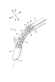
図1は、本実施形態の内視鏡11の全体構成図である。図1に示す内視鏡11は、主に把持部13と、連結部15と、連結部15を介して把持部13と連結された直線パイプ状で湾曲不能な直線部17と、湾曲可能に構成された屈曲部19と、機能部材の一例としての撮像ユニット21が収納された硬性部23と、直線部17をその延在方向を軸として回動させる回転操作部25とを含む構成である。硬性部23は、内視鏡11の挿入方向の先端に設けられる。   FIG. 1 is an overall configuration diagram of an endoscope 11 according to the present embodiment. The endoscope 11 shown in FIG. 1 mainly has a gripping part 13, a connecting part 15, a straight pipe-like straight part 17 connected to the gripping part 13 via the connecting part 15, and a bendable part. The configuration includes a configured bending portion 19, a rigid portion 23 in which an imaging unit 21 as an example of a functional member is accommodated, and a rotation operation portion 25 that rotates the linear portion 17 about its extending direction. . The rigid portion 23 is provided at the distal end in the insertion direction of the endoscope 11.

ここで、硬性部23の先端から回転操作部25の後端までの長さL1は例えば約600mm、硬性部23の長さL2は例えば約15mm、屈曲部19の長さL3は例えば約60mm、直線部17の長さL4は例えば約450mm程度であり、また硬性部23、屈曲部19、直線部17の外径は最大部分で例えば約10mm程度とされている。手術の際には、このうち硬性部23と屈曲部19とがトロッカーやトロッカーチューブを介して患部まで案内されて体腔に挿入される。一方、直線部17の一部は体外に出た状態で術式が執り行われる。   Here, the length L1 from the front end of the hard part 23 to the rear end of the rotation operation part 25 is, for example, about 600 mm, the length L2 of the hard part 23 is, for example, about 15 mm, and the length L3 of the bent part 19 is, for example, about 60 mm. The length L4 of the straight portion 17 is about 450 mm, for example, and the outer diameters of the hard portion 23, the bent portion 19 and the straight portion 17 are about 10 mm at the maximum portion, for example. During surgery, the hard part 23 and the bent part 19 are guided to the affected part through a trocar or trocar tube and inserted into the body cavity. On the other hand, the surgical procedure is performed while a part of the straight portion 17 is out of the body.

把持部13には、屈曲部19を湾曲させるべく操作を行う第1操作部27と、硬性部23に搭載された撮像ユニット21による撮像方向を操作する第2操作部29とが設けられている。施術者等が第1操作部27を操作すると、屈曲部19はその操作量に応じて所定の方向(例えば下方)に向けて湾曲し、硬性部23に設けられた撮像ユニット21の撮像方向が変化、即ち視野が移動する。把持部13において、第1操作部27は第1軸31を中心として回転可能であり、操作性を考慮して、この回転方向と屈曲部19の湾曲方向とが一致するように設計されている。   The grip portion 13 is provided with a first operation portion 27 that performs an operation to bend the bending portion 19 and a second operation portion 29 that operates an imaging direction by the imaging unit 21 mounted on the rigid portion 23. . When a practitioner or the like operates the first operation unit 27, the bending portion 19 bends in a predetermined direction (for example, downward) according to the operation amount, and the imaging direction of the imaging unit 21 provided in the rigid portion 23 is changed. Change, ie the field of view moves. In the grip portion 13, the first operation portion 27 can rotate around the first shaft 31, and is designed so that the rotation direction and the bending direction of the bending portion 19 coincide with each other in consideration of operability. .

なお、以降の説明において、第1操作部27の操作によって屈曲部19が湾曲し、これによって視野を移動させる動作を「湾曲動作」、湾曲によって硬性部23の先端が向く方向と直線部17の軸方向(第2軸33)とがなす角度を「湾曲角度」、前面視において湾曲によって硬性部23の先端が向く方向を「湾曲方向」のように呼称することがある。そして、例えば硬性部23の先端が下方(上方)に向くように屈曲部19が湾曲することを「下方(上方)に向けて湾曲する」のように表現することがある。   In the following description, the bending portion 19 is bent by the operation of the first operating portion 27 and the movement of the field of view is thereby moved as a “curving operation”, and the direction in which the tip of the rigid portion 23 faces by the bending and the straight portion 17 An angle formed by the axial direction (second axis 33) may be referred to as a “curving angle”, and a direction in which the tip of the rigid portion 23 faces by bending in front view may be referred to as a “curving direction”. For example, the bending of the bending portion 19 so that the tip of the rigid portion 23 faces downward (upward) may be expressed as “curving downward (upward)”.

また、第2操作部29も第1軸31を中心として回動し、施術者等が第2操作部29を操作すると、硬性部23に枢支された撮像ユニット21の視野が、ここでは前方と下方との間を移動する。なお、以降の説明において、第2操作部29を操作することによって視野を移動させる動作を「チルト動作」、あるいは単に「チルト」と呼称する。なお、第1操作部27及び第2操作部29は、把持部13に設けられたストッパ(図示せず)によって操作範囲(第1軸31を軸とする回動範囲)が規制されている。なお、第1操作部27、第2操作部29は図示するようなレバー式の他、回転グリップ等を用いてもよい。さらに、チルト操作部は把持部13以外に設けられていても構わない。   The second operation unit 29 also rotates about the first shaft 31, and when a practitioner or the like operates the second operation unit 29, the field of view of the imaging unit 21 pivotally supported by the rigid unit 23 is here forward. Move between and below. In the following description, the operation of moving the visual field by operating the second operation unit 29 is referred to as “tilt operation” or simply “tilt”. The first operation unit 27 and the second operation unit 29 are restricted in operation range (a rotation range about the first shaft 31) by a stopper (not shown) provided in the grip unit 13. The first operation unit 27 and the second operation unit 29 may be a lever type as shown in the figure, or a rotary grip or the like. Further, the tilt operation unit may be provided in addition to the grip unit 13.

図1は、内視鏡11の初期状態を示しており、このとき屈曲部19は直線状で、かつ硬性部23における撮像ユニット21の視野は前方を向いている。この状態から、第1操作部27を操作すると屈曲部19は下方に向けて湾曲し、第2操作部29を操作すると撮像ユニット21は下方に向けてチルト動作する。ここで、屈曲部19の湾曲角度を0°〜90°、撮像ユニット21のチルト角度を0°〜90゜とすれば、湾曲動作とチルト動作とを組み合わせることで、屈曲部19の湾曲角度を大きくせずとも(即ち、湾曲の際に大きな空間を占めることなく)視野の移動範囲を0°〜180゜まで拡大することが可能となる。即ち、内視鏡11は、初期状態として直線状であった屈曲部19が湾曲することで機能部材の先端が向く方向(撮像方向)と、枢支された機能部材が回動することで機能部材の先端が向く方向とが、略同一とされている。   FIG. 1 shows an initial state of the endoscope 11. At this time, the bent portion 19 is linear, and the field of view of the imaging unit 21 in the hard portion 23 faces frontward. In this state, when the first operation unit 27 is operated, the bending portion 19 is bent downward, and when the second operation unit 29 is operated, the imaging unit 21 is tilted downward. Here, if the bending angle of the bending portion 19 is 0 ° to 90 ° and the tilt angle of the imaging unit 21 is 0 ° to 90 °, the bending angle of the bending portion 19 can be increased by combining the bending operation and the tilting operation. Even if it is not increased (that is, it does not occupy a large space during bending), the moving range of the visual field can be expanded to 0 ° to 180 °. That is, the endoscope 11 functions by rotating the pivoted functional member in the direction in which the distal end of the functional member faces (imaging direction) when the bent portion 19 which is linear in the initial state is curved. The direction in which the tip of the member faces is substantially the same.

把持部13の前方には連結部15が設けられている。連結部15は、把持部13に支持されるとともに、その前方において直線部17に接続されている。後述するように、第1操作部27の操作によって発生した力はリンク部材35によって連結部15に伝達され、連結部15ではこの力を牽引力として屈曲部19の遊端37まで伝達する。   A connecting portion 15 is provided in front of the grip portion 13. The connecting portion 15 is supported by the grip portion 13 and connected to the straight portion 17 in front of the connecting portion 15. As will be described later, the force generated by the operation of the first operation portion 27 is transmitted to the connecting portion 15 by the link member 35, and this force is transmitted as the traction force to the free end 37 of the bending portion 19.

直線部17は、屈曲部19の基端39の側に一端が取り付けられ、第2軸方向に延在する中空部41(図3等参照)を有する筒状かつ直線状の部材であり、ここではステンレス鋼で構成されている。直線部17は連結部15を介して把持部13に連結されて、把持部13から前方に向けて延伸されている。第2操作部29の操作によって発生した力は(以降、第2操作部29や第1操作部27等を操作することで発生した力を「操作力」と呼称する)、把持部13の内部に設けられたギア機構によって第2軸33を軸とする回転力に変換され、この回転力が硬性部23まで伝達される。なお、連結部15には第2軸方向に貫通する軸受開口部(図示略)が設けられており、回転力は連結部15を経由することなく直接的に硬性部23に向けて伝達される。   The straight portion 17 is a cylindrical and straight member having a hollow portion 41 (see FIG. 3 and the like) having one end attached to the base end 39 side of the bent portion 19 and extending in the second axial direction. In, it is made of stainless steel. The straight line portion 17 is connected to the grip portion 13 via the connection portion 15 and extends forward from the grip portion 13. The force generated by the operation of the second operation unit 29 (hereinafter, the force generated by operating the second operation unit 29, the first operation unit 27, etc. will be referred to as “operation force”). It is converted into a rotational force about the second shaft 33 by the gear mechanism provided in, and this rotational force is transmitted to the rigid portion 23. The connecting portion 15 is provided with a bearing opening (not shown) penetrating in the second axial direction, and the rotational force is directly transmitted to the rigid portion 23 without passing through the connecting portion 15. .

なお、把持部13は観察対象(例えば人体)の内部を撮影して得られた静止画及び動画に対して画像処理等を行うビデオプロセッサ43と接続されており、ビデオプロセッサ43で処理された画像はディスプレイ装置45に表示される。一方、内視鏡11はビデオプロセッサ43から電力や各種の制御信号を受け取り、制御信号に基づくタイミングで撮像ユニット21において撮像が行われる。   The gripping unit 13 is connected to a video processor 43 that performs image processing or the like on a still image and a moving image obtained by photographing the inside of an observation target (for example, a human body), and an image processed by the video processor 43 Is displayed on the display device 45. On the other hand, the endoscope 11 receives power and various control signals from the video processor 43, and the imaging unit 21 performs imaging at a timing based on the control signals.

図2は、屈曲部19の構成を示す斜視図である。図示するように、屈曲部19は基端39から遊端37にかけて延在しており、基端39と遊端37との間において連結された複数の節輪47から構成される。以降の説明で、複数の節輪47の集合体が構成する軸を「屈曲部19の軸」、その方向を「屈曲部19の軸方向」のように呼称することがある。屈曲部19は湾曲可能であることから、「屈曲部19の軸方向」は湾曲方向及び湾曲角度に応じて変化する。   FIG. 2 is a perspective view showing the configuration of the bent portion 19. As shown in the drawing, the bent portion 19 extends from the base end 39 to the free end 37 and is composed of a plurality of node rings 47 connected between the base end 39 and the free end 37. In the following description, the axis formed by the aggregate of the plurality of node rings 47 may be referred to as “the axis of the bent portion 19”, and the direction thereof may be referred to as “the axial direction of the bent portion 19”. Since the bent portion 19 can be bent, the “axial direction of the bent portion 19” changes according to the bending direction and the bending angle.

節輪47は、例えばステンレス鋼で構成され、屈曲部19の軸方向から見たときに略矩形状をなす部材であり、いずれも同一形状に設計されている。各節輪47は、前面視で左右(又は上下)対称の位置に係合部49を有し、節輪47は係合部49を回動中心として隣接する節輪47に対して所定角度だけ回動可能に構成されている。屈曲部19の軸方向から見たときに、係合部49を周方向に交互に90°ずつずらして複数の節輪47を連結することで、屈曲部19の遊端37は基端39に対して任意の方向に湾曲可能に構成されている。   The node ring 47 is made of, for example, stainless steel, and is a member having a substantially rectangular shape when viewed from the axial direction of the bent portion 19, and both are designed to have the same shape. Each node ring 47 has an engagement portion 49 at a symmetrical position in the left-right (or vertical) view from the front, and the node ring 47 has a predetermined angle with respect to the adjacent node ring 47 with the engagement portion 49 as a rotation center. It is configured to be rotatable. When viewed from the axial direction of the bent portion 19, the free ends 37 of the bent portion 19 are connected to the base end 39 by connecting the plurality of node rings 47 by alternately shifting the engaging portions 49 by 90 ° in the circumferential direction. On the other hand, it can be bent in any direction.

また、矩形形状の節輪47のうち、係合部49が形成されていない辺には、屈曲部19の外縁から内径方向に屈曲するように形成されたワイヤ導通片51が設けられ、ワイヤ導通片51に形成された貫通孔に後述する制御ワイヤ53(図3等参照)が延設される。   In addition, a wire conducting piece 51 formed so as to bend in the inner diameter direction from the outer edge of the bent portion 19 is provided on the side of the rectangular node ring 47 where the engaging portion 49 is not formed. A control wire 53 (see FIG. 3 or the like), which will be described later, is extended in a through hole formed in the piece 51.

また、周方向に係合部49とワイヤ導通片51(図5、6参照)との間、即ち、前面視で略矩形状の節輪47の角部分には、節輪47の外面から凹陥する第1溝部55が設けられている。屈曲部全体をみたとき、第1溝部55は屈曲部19の軸に沿って延設され、第1溝部55には撮像ユニット21から引き出されて画像データをビデオプロセッサ43に伝送する信号線、電源ライン等を束ねた伝送ケーブル57が収納されている。ただし、屈曲部19が湾曲すると屈曲部19の外面では軸方向の長さが変化することから、伝送ケーブル57は第1溝部55に対して相対的に変位可能(即ち、屈曲部19の軸に沿って摺動可能)に収納されている。なお、第1溝部55が形成されている節輪47の角部分とは異なる他の角部分には第2溝部59が延設されている。   In addition, a recess is formed from the outer surface of the node ring 47 between the engaging portion 49 and the wire conducting piece 51 (see FIGS. 5 and 6) in the circumferential direction, that is, at a corner portion of the node ring 47 having a substantially rectangular shape in front view. A first groove portion 55 is provided. When the entire bent portion is viewed, the first groove portion 55 extends along the axis of the bent portion 19, and the first groove portion 55 has a signal line that is pulled out from the imaging unit 21 and transmits image data to the video processor 43, a power source A transmission cable 57 in which lines and the like are bundled is stored. However, since the length in the axial direction changes on the outer surface of the bent portion 19 when the bent portion 19 is bent, the transmission cable 57 can be displaced relative to the first groove portion 55 (that is, on the axis of the bent portion 19). Is slidable along). Note that a second groove portion 59 is extended at another corner portion different from the corner portion of the node ring 47 in which the first groove portion 55 is formed.

第2溝部59には、例えば硬性部23の先端に向けて照明光を伝送する光ファイバ束や、洗浄液を供給する送水管(いずれも図示せず)が収納される。また、図2に現れない背面側に、他の溝部を別途付加してもよく、硬性部23に撮像ユニット以外の機能部材を搭載する場合に、その機能部材が機械的な駆動力を必要とする場合(例えば機能部材が鉗子や超音波メスであるような場合)は、他の溝部にパイプを延設し、このパイプ内に挿通されたワイヤ等を介して駆動力を伝達してもよい。なお、屈曲部19の外周を柔軟性の高い被覆材(図示せず)で覆うようにしてもよい。   In the second groove portion 59, for example, an optical fiber bundle that transmits illumination light toward the tip of the rigid portion 23 and a water supply pipe that supplies cleaning liquid (none of which are shown) are stored. In addition, another groove portion may be separately added on the back side that does not appear in FIG. 2, and when a functional member other than the imaging unit is mounted on the rigid portion 23, the functional member requires a mechanical driving force. In the case where the functional member is a forceps or an ultrasonic scalpel, for example, a pipe may be extended to another groove portion, and the driving force may be transmitted via a wire inserted into the pipe. . The outer periphery of the bent portion 19 may be covered with a highly flexible coating material (not shown).

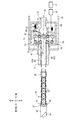
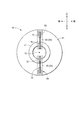
図3は、連結部15の基本構成及び連結部15の状態と屈曲部19の湾曲状態との関連を示す説明図である。図4は、連結部15を構成する牽引部材61及びワイヤガイド63を前方からみた概略構成図である。図3は、屈曲部19が直線状となっている状態(初期状態)を示している。以下、図3及び図4を用いて、屈曲部19が一方向(ここでは上下方向)に湾曲可能にされた基本構成について説明する。   FIG. 3 is an explanatory diagram showing the basic configuration of the connecting portion 15 and the relationship between the state of the connecting portion 15 and the bent state of the bent portion 19. FIG. 4 is a schematic configuration diagram of the pulling member 61 and the wire guide 63 constituting the connecting portion 15 as viewed from the front. FIG. 3 shows a state (initial state) where the bent portion 19 is linear. Hereinafter, a basic configuration in which the bent portion 19 can be bent in one direction (here, the vertical direction) will be described with reference to FIGS. 3 and 4.

連結部15は、連結部筐体65と、連結部筐体内に設けられた牽引部材61及びワイヤガイド63とで構成されている。牽引部材61を挟んで直線部17と反対側には、球体軸受67が把持部13から前方に突出するように設けられ、連結部筐体65は、その後部において球体軸受67の軸部分に第2軸33を軸とする回動及び前後方向への移動を規制された状態で固定され、その前部において第2軸33を軸として直線部17を回動自在に支持している。連結部筐体65によって、直線部17の軸は球体軸受67の軸(第2軸33)と常に一致するよう、即ち同軸度を維持されて支持されている。   The connecting portion 15 includes a connecting portion casing 65, a pulling member 61 and a wire guide 63 provided in the connecting portion casing. A spherical bearing 67 is provided on the opposite side of the linear portion 17 across the traction member 61 so as to protrude forward from the grip portion 13, and the connecting portion housing 65 is connected to the shaft portion of the spherical bearing 67 at the rear portion. Rotation about the two axes 33 and movement in the front-rear direction are fixed, and the linear portion 17 is supported rotatably at the front portion about the second shaft 33 as an axis. The connecting part housing 65 supports the linear part 17 so that the axis of the linear part 17 always coincides with the axis of the spherical bearing 67 (second axis 33), that is, the coaxiality is maintained.

図4に示すように、牽引部材61は前面視で円形状をなす円盤状の部材であって、図3に示すように、後方に設けられた静止部69と前方に設けられた回動部71とで構成される。静止部69は後方から球体軸受67によって支持されている。球体軸受67は、牽引部材61の全体が前後方向に移動することを規制する一方で、直線部17の軸(第2軸33)と直交する面に対して、牽引部材61(静止部69)を任意方向に傾斜可能に支持している。一方、回動部71は静止部69に対して相対的に回動可能とされている。   As shown in FIG. 4, the pulling member 61 is a disk-shaped member that is circular in a front view, and as shown in FIG. 3, a stationary portion 69 provided at the rear and a rotating portion provided at the front. 71. The stationary portion 69 is supported by a spherical bearing 67 from the rear. The spherical bearing 67 restricts the entire traction member 61 from moving in the front-rear direction, while the traction member 61 (stationary portion 69) with respect to a plane orthogonal to the axis of the linear portion 17 (second axis 33). Is supported to be tiltable in an arbitrary direction. On the other hand, the rotation part 71 is rotatable relative to the stationary part 69.

ワイヤガイド63は、主に第1定滑車73と第2定滑車75とで構成される部材であり、基本構成では、2つのワイヤガイド63が直線部17の上下に固定されている。   The wire guide 63 is a member mainly composed of a first constant pulley 73 and a second constant pulley 75. In the basic configuration, the two wire guides 63 are fixed above and below the linear portion 17.

図3に示すように、牽引部材61の回動部71には、第2軸33を挟んで上下2カ所にガイド軸77が設けられる。ガイド軸77は、円盤状の回動部71に穿設した軸収容穴(図示略)内に設けられる。一方、直線部17の後端からは、軸収容穴に挿入される突出片部(図示略)が突設される。この突出片部には、前後方向に長い長孔としてのガイド孔79が形成される。回動部71のガイド軸77は、直線部17の後端から突出した突出片部のガイド孔79に係合されている。ガイド軸77とガイド孔79とは係合機構を構成する。この係合機構によって牽引部材61は直線部17の後端の側においても支持され、直線部17(第2軸33)に対して相対的に変位(傾斜)可能とされている。即ち、回動部71は、直線部17の軸と直交する面に対して傾斜可能で、かつ傾斜した状態で直線部17とともに回動する。   As shown in FIG. 3, the rotating portion 71 of the pulling member 61 is provided with guide shafts 77 at two positions on the upper and lower sides with the second shaft 33 interposed therebetween. The guide shaft 77 is provided in a shaft housing hole (not shown) drilled in the disc-shaped rotating portion 71. On the other hand, a protruding piece portion (not shown) that is inserted into the shaft accommodating hole protrudes from the rear end of the linear portion 17. A guide hole 79 as a long hole that is long in the front-rear direction is formed in the protruding piece. The guide shaft 77 of the rotating portion 71 is engaged with a guide hole 79 of a protruding piece portion protruding from the rear end of the linear portion 17. The guide shaft 77 and the guide hole 79 constitute an engagement mechanism. By this engagement mechanism, the pulling member 61 is also supported on the rear end side of the linear portion 17 and can be displaced (inclined) relative to the linear portion 17 (second shaft 33). That is, the rotation part 71 can be inclined with respect to a plane orthogonal to the axis of the linear part 17 and rotates together with the linear part 17 in an inclined state.

上述したように、直線部17は連結部筐体65によって球体軸受67との同軸度を維持され、一方で牽引部材61は球体軸受67によって傾斜可能とされているため、本実施形態の内視鏡11の構成によれば、連結部15の前後で把持部13(球体軸受67)と直線部17との相対的な位置関係は不変のまま(即ち、両者の同軸度が維持されたまま)で、連結部内において牽引部材61の傾斜方向及び傾斜角度が変化する。ただし、ガイド軸77とガイド孔79による係合構造が設けられることで、牽引部材61が傾斜可能な方向は限定される。   As described above, the linear portion 17 is maintained coaxial with the spherical bearing 67 by the connecting portion housing 65, while the traction member 61 can be tilted by the spherical bearing 67. According to the configuration of the mirror 11, the relative positional relationship between the gripping portion 13 (spherical bearing 67) and the linear portion 17 remains unchanged before and after the connecting portion 15 (that is, the coaxiality of the both is maintained). Thus, the inclination direction and the inclination angle of the traction member 61 change in the connecting portion. However, the direction in which the pulling member 61 can be tilted is limited by providing the engagement structure by the guide shaft 77 and the guide hole 79.

図3に示すように、牽引部材61の上部は、連結部15の内部において、コイルバネ等の弾性体で構成された付勢部材81によって常時後方に向けて付勢されており、他方、牽引部材61の下部は上述したリンク部材35を介して第1操作部27によって後方に牽引されている。   As shown in FIG. 3, the upper portion of the traction member 61 is constantly urged rearward by an urging member 81 made of an elastic body such as a coil spring inside the connecting portion 15, while the traction member The lower portion of 61 is pulled backward by the first operating portion 27 via the link member 35 described above.

また、牽引部材61の外周部において、上方には第1制御ワイヤ83が、下方には第2制御ワイヤ85の始端が固定されている(以降、これらをまとめて制御ワイヤ53と呼称することがある)。制御ワイヤ53としては、例えばステンレスワイヤの撚糸等を好適に用いることができる。制御ワイヤ53は第1動力伝達部材を構成し、制御ワイヤ53の始端側は牽引部材61によって後方に牽引される。基本構成では、制御ワイヤ53は牽引部材61の外周部において、第2軸33を挟んで周方向に180゜離間した部位(例えば、上下方向の外周部)に始端が固定されている。制御ワイヤ53の固定位置に対応して牽引部材61の前方にワイヤガイド63が設けられている。   Further, in the outer peripheral portion of the pulling member 61, the first control wire 83 is fixed on the upper side, and the starting end of the second control wire 85 is fixed on the lower side (hereinafter, these may be collectively referred to as the control wire 53). is there). As the control wire 53, for example, a twisted wire of a stainless wire can be suitably used. The control wire 53 constitutes a first power transmission member, and the starting end side of the control wire 53 is pulled backward by the pulling member 61. In the basic configuration, the starting end of the control wire 53 is fixed to a portion (for example, the outer peripheral portion in the vertical direction) spaced apart by 180 ° in the circumferential direction across the second shaft 33 in the outer peripheral portion of the pulling member 61. A wire guide 63 is provided in front of the pulling member 61 corresponding to the fixed position of the control wire 53.

ワイヤガイド63は、直線部17の外周に相対変位不能に固定され、外周側に設けられた第1定滑車73と内周側に設けられた第2定滑車75とで構成される。制御ワイヤ53は、まず第1定滑車73によって外周側から内周側へと延伸方向を変えられ、次に第2定滑車75によって後方から前方へと延伸方向を変えられる。第2定滑車75によって延伸方向を前方に変えられた制御ワイヤ53は筒状の直線部17の中空部内を屈曲部19の基端39まで導かれ、次いで屈曲部19の内側に向けて突出したワイヤ導通片51(図2参照)の導通孔を順次経由して屈曲部19の遊端側に導かれる。   The wire guide 63 is fixed to the outer periphery of the linear portion 17 so as not to be relatively displaced, and includes a first constant pulley 73 provided on the outer peripheral side and a second constant pulley 75 provided on the inner peripheral side. The extending direction of the control wire 53 is first changed from the outer peripheral side to the inner peripheral side by the first constant pulley 73, and then the extending direction is changed from the rear to the front by the second constant pulley 75. The control wire 53 whose extension direction has been changed forward by the second constant pulley 75 is guided to the proximal end 39 of the bent portion 19 through the hollow portion of the cylindrical straight portion 17 and then protrudes toward the inside of the bent portion 19. The wire is led to the free end side of the bent portion 19 through the conduction holes of the wire conduction piece 51 (see FIG. 2) sequentially.

そして、図3に示すように、第1制御ワイヤ83の終端は、屈曲部19の遊端側の内面において、屈曲部19の上方に設けられた第1固定点87に固定され、同様に第2制御ワイヤ85は、屈曲部19の下方に設けられた第2固定点89に固定される。   As shown in FIG. 3, the end of the first control wire 83 is fixed to a first fixing point 87 provided above the bent portion 19 on the inner surface of the bent portion 19 on the free end side. 2 The control wire 85 is fixed to a second fixing point 89 provided below the bent portion 19.

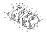
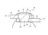
図5は、複数の節輪47が連結された節輪構造体の拡大斜視図である。図6は、図5に示した節輪構造体の縦断面図である。   FIG. 5 is an enlarged perspective view of a node ring structure in which a plurality of node rings 47 are connected. FIG. 6 is a longitudinal sectional view of the node ring structure shown in FIG.

本実施形態の内視鏡11の屈曲部19は、硬性部23に遊端37が接続され、基端39との間で複数の節輪47が係合により連結されることによって節輪構造体が構成されている。節輪構造体は、それぞれの節輪47が相互に変位(回転)することで湾曲自在となる。   The bending portion 19 of the endoscope 11 of the present embodiment has a node ring structure in which a free end 37 is connected to the rigid portion 23 and a plurality of node rings 47 are coupled to the base end 39 by engagement. Is configured. The node ring structure is free to bend as the respective node rings 47 are displaced (rotated) from each other.

節輪同士の係合部49は、隣接する一方の節輪47から軸線方向に突出する外側係合片91と、隣接する他方の節輪47から軸線方向に突出する内側係合片93と、を有する。外側係合片91と、内側係合片93とは、一つの節輪47に一対ずつ設けられている。一対の外側係合片91は、節輪47の軸線方向一端側において、直径方向の両端側に設けられる。   The engagement portions 49 between the node rings include an outer engagement piece 91 protruding in the axial direction from one adjacent node ring 47, an inner engagement piece 93 protruding in the axial direction from the other adjacent node ring 47, and Have A pair of outer engagement pieces 91 and inner engagement pieces 93 are provided on each node ring 47. The pair of outer engagement pieces 91 are provided on both ends in the diametrical direction on one axial end of the node ring 47.

一方、一対の内側係合片93は、節輪47の軸線方向他端側において、上述した直径方向と直交する直径方向の両端側に設けられる。つまり、外側係合片91と内側係合片93は、一つの節輪47において、軸線方向の両側で、90°回転された位置で配置されている。これにより、屈曲部19は、上述したように、節輪47を周方向に交互に90゜ずつずらして複数を連結することで、遊端37が基端39に対して任意の方向に湾曲可能な構造となっている。   On the other hand, the pair of inner engagement pieces 93 are provided on both ends in the diametrical direction orthogonal to the above-described diametrical direction on the other axial end of the node ring 47. That is, the outer engagement piece 91 and the inner engagement piece 93 are disposed at a position rotated 90 ° on both sides in the axial direction in one node ring 47. As a result, as described above, the bending portion 19 can be bent in any direction with respect to the base end 39 by connecting the plurality of the node rings 47 by alternately shifting the node rings 47 by 90 ° in the circumferential direction. It has a simple structure.

この外側係合片91と内側係合片93とは、相互に重ね合わされて、鋲状部材95によって連結される。鋲状部材95は、頭部97と、この頭部97より小径の軸部99を有する。外側係合片91には、外側貫通穴101が穿設される。内側係合片93には、内側貫通穴103が穿設される。鋲状部材95は、外側貫通穴101から軸部99が貫通して、内側係合片93の内側貫通穴103に挿入される。この鋲状部材95は、外側係合片91又は内側係合片93の一方に接合される。外側貫通穴101を貫通し、内側貫通穴103に挿通された軸部99は、軸先端面105が内側係合片93の貫通穴開口面107と略同一面に配置される。   The outer engagement piece 91 and the inner engagement piece 93 are overlapped with each other and connected by a hook-shaped member 95. The hook-shaped member 95 has a head portion 97 and a shaft portion 99 having a smaller diameter than the head portion 97. An outer through hole 101 is formed in the outer engagement piece 91. An inner through hole 103 is formed in the inner engagement piece 93. The hook-like member 95 is inserted into the inner through hole 103 of the inner engagement piece 93 through the shaft portion 99 from the outer through hole 101. The hook-like member 95 is joined to one of the outer engagement piece 91 and the inner engagement piece 93. The shaft portion 99 that passes through the outer through hole 101 and is inserted into the inner through hole 103 has the shaft tip surface 105 disposed substantially flush with the through hole opening surface 107 of the inner engagement piece 93.

鋲状部材95の軸先端面105が、貫通穴開口面107と同一平面で配置された内側係合片93は、節輪47が所定の剛性を有していることで、半径方向の内側には若干量(内側係合片93の板厚み以下)の変形しか生じない。このため、軸先端面105から内側係合片93の内側貫通穴103が離脱することはない。   The inner engagement piece 93 in which the shaft front end surface 105 of the hook-shaped member 95 is arranged in the same plane as the through-hole opening surface 107 has a predetermined rigidity, so that Only a slight amount of deformation (below the plate thickness of the inner engagement piece 93) occurs. For this reason, the inner through hole 103 of the inner engagement piece 93 is not detached from the shaft tip surface 105.

このように、鋲状部材95は、軸先端面105が、内側係合片93の貫通穴開口面107と略同一面に配置される。ここで、略同一面の「略」とは、軸先端面105は基本的に内側係合片93の貫通穴開口面107と同一面であるが、製造公差や組付公差によって貫通穴開口面107から軸先端面105が若干突出する程度のものは、軸先端面105と貫通穴開口面107とが同一面であることを含むものとする。   As described above, the flange-shaped member 95 has the shaft tip surface 105 disposed on the same plane as the through hole opening surface 107 of the inner engagement piece 93. Here, “substantially” of substantially the same surface means that the shaft tip surface 105 is basically the same surface as the through-hole opening surface 107 of the inner engagement piece 93, but the through-hole opening surface depends on manufacturing tolerances and assembly tolerances. The shape in which the shaft tip surface 105 slightly protrudes from 107 includes that the shaft tip surface 105 and the through hole opening surface 107 are the same surface.

内視鏡11は、頭部97が、外側係合片91に接着又は溶接によって接合される。接着は、例えば接着剤によって行うことができる。また、接合は、ロー付けを含む。鋲状部材95と節輪47がステンレス鋼である場合、ロー付けは、例えば銀ローを用いることによって可能となる。また、溶接は、例えば超音波接合、抵抗溶接、レーザー溶接、ガス溶接等によって行うことができる。鋲状部材95と節輪47がステンレス鋼である場合、溶接は、例えばアルゴン溶接によって行うことができる。   The head portion 97 of the endoscope 11 is joined to the outer engagement piece 91 by bonding or welding. Adhesion can be performed with an adhesive, for example. Bonding also includes brazing. When the saddle member 95 and the node ring 47 are made of stainless steel, brazing can be performed by using, for example, silver solder. The welding can be performed by, for example, ultrasonic bonding, resistance welding, laser welding, gas welding, or the like. When the hook-shaped member 95 and the node ring 47 are stainless steel, welding can be performed by, for example, argon welding.

図7(A)及び(B)は、鋲状部材95と係合部49の分解斜視図である。図8は、図6の係合部49における要部拡大図である。図7(A)は鋲状部材95の分解斜視図であり、図7(B)は係合部49の分解斜視図である。   7A and 7B are exploded perspective views of the hook-shaped member 95 and the engaging portion 49. FIG. FIG. 8 is an enlarged view of a main part of the engaging portion 49 of FIG. FIG. 7A is an exploded perspective view of the hook-shaped member 95, and FIG. 7B is an exploded perspective view of the engaging portion 49.

内視鏡11は、外側係合片91の外側貫通穴101に、軸部99が螺合することによって頭部97が外側係合片91に接合されてもよい。即ち、軸部99には外側係合片91の厚みt分(図8参照)の雄ネジ109が形成され、外側貫通穴101にはこの雄ネジ109に螺合する雌ネジ111が形成される。この螺合によって、鋲状部材95は、螺合部分と頭部97とで、外側係合片91に固定(頭部97が外側係合片91に接合)される。   In the endoscope 11, the head portion 97 may be joined to the outer engagement piece 91 by screwing the shaft portion 99 into the outer through hole 101 of the outer engagement piece 91. That is, a male screw 109 corresponding to the thickness t of the outer engagement piece 91 (see FIG. 8) is formed on the shaft portion 99, and a female screw 111 that is screwed into the male screw 109 is formed in the outer through hole 101. . By this screwing, the hook-like member 95 is fixed to the outer engaging piece 91 (the head 97 is joined to the outer engaging piece 91) at the screwed portion and the head 97.

次に、上述した構成を有する本実施形態の内視鏡11の作用を説明する。   Next, the operation of the endoscope 11 of the present embodiment having the above-described configuration will be described.

図9は、連結部15の基本構成及び連結部15の状態と屈曲部19の湾曲状態との関連を示す説明図である。   FIG. 9 is an explanatory diagram showing the basic configuration of the connecting portion 15 and the relationship between the state of the connecting portion 15 and the bent state of the bent portion 19.

図3に示す屈曲部19の初期状態において、第1操作部27を操作して、牽引部材61の下部に後方に向けて操作力を付与すると、図9に示すように、牽引部材61は第1操作部27の操作量に応じて、第2軸33に直交する面に対して第3軸113を軸として角度θだけ傾斜する。牽引部材61の傾斜に伴って第2制御ワイヤ85が後方に牽引され、屈曲部19の遊端37の側において第2固定点89が牽引されて、最終的に屈曲部19は下方に向けて湾曲する。このとき、屈曲部19の湾曲に伴って、第1固定点87に接続された第1制御ワイヤ83は前方に向けて繰り出されることになる。   In the initial state of the bent portion 19 shown in FIG. 3, when the first operating portion 27 is operated to apply an operating force to the lower portion of the pulling member 61 toward the rear, as shown in FIG. In accordance with the amount of operation of the first operation unit 27, the surface is inclined by an angle θ about the third axis 113 with respect to the plane orthogonal to the second axis 33. As the pulling member 61 is inclined, the second control wire 85 is pulled backward, the second fixing point 89 is pulled on the free end 37 side of the bent portion 19, and finally the bent portion 19 is directed downward. Bend. At this time, the first control wire 83 connected to the first fixing point 87 is drawn forward with the bending portion 19 being curved.

なお、牽引部材61によって制御ワイヤ53が引き出される長さ(以降、「牽引量」と呼称する)は、第3軸113を軸とする牽引部材61の傾斜角度と、制御ワイヤ53の始端が牽引部材61に固定されている位置と第3軸113(正確には、制御ワイヤ53の始端が固定されている面と第2軸33との交点)までの距離との両方によって決定される。従って、牽引部材61の外径を大きくすることによって牽引量が増大され、これによって屈曲部19の湾曲角度を大きくすることができる。牽引部材61が収納される連結部筐体65は体外にあるため、外径のサイズについては特に制限を受けることはない。   Note that the length of the control wire 53 drawn by the traction member 61 (hereinafter referred to as “traction amount”) is determined by the inclination angle of the traction member 61 about the third shaft 113 and the start end of the control wire 53. It is determined by both the position fixed to the member 61 and the distance to the third axis 113 (more precisely, the intersection of the surface where the starting end of the control wire 53 is fixed and the second axis 33). Therefore, the amount of traction is increased by increasing the outer diameter of the traction member 61, whereby the bending angle of the bent portion 19 can be increased. Since the connecting portion housing 65 in which the pulling member 61 is housed is outside the body, the size of the outer diameter is not particularly limited.

また、ここでは図3に示すように屈曲部19が湾曲していない状態を初期状態としているが、付勢部材81の張力を調整して、屈曲部19が上方に向けて湾曲する状態を初期状態としてもよい。このようにすることで、第1操作部27の操作によって、屈曲部19は上方に向けて湾曲した状態から図3に示す直線状態となり、更に操作を加えることで、図4に示すように下方に向けて湾曲した状態まで変位させることが可能となる。   Here, as shown in FIG. 3, the initial state is a state where the bent portion 19 is not curved, but the initial state is a state where the bent portion 19 is bent upward by adjusting the tension of the biasing member 81. It is good also as a state. By doing so, the bending portion 19 is changed from the state of being bent upward to the linear state shown in FIG. 3 by the operation of the first operation portion 27, and by further operation, as shown in FIG. It is possible to displace the lens to a curved state.

また、連結部15の基本構成では、連結部筐体65の内部において、牽引部材61の上部は付勢部材81によって後方に付勢されるとしているが、牽引部材61の上部もリンク部材35と結合して、上下でプッシュプル構成としてもよい。このようにすることで、第1操作部27の操作に基づいて第1制御ワイヤ83を牽引して、図3に示す屈曲部19の初期状態から、屈曲部19を上方に向けて湾曲させることが可能となる。   In the basic configuration of the connecting portion 15, the upper portion of the traction member 61 is urged rearward by the urging member 81 inside the linking portion housing 65, but the upper portion of the traction member 61 is also connected to the link member 35. They may be combined to form a push-pull configuration at the top and bottom. In this way, the first control wire 83 is pulled based on the operation of the first operation unit 27, and the bending portion 19 is bent upward from the initial state of the bending portion 19 shown in FIG. Is possible.

また、例えば隣接する節輪47の間をバネ等の弾性部材(図示せず)で連結して、屈曲部19が初期状態として自律的に直線状態(あるいは上述した、上方に向けて湾曲した状態)を維持するように構成してもよい。この場合、制御ワイヤ53を牽引しない場合、屈曲部19は自身が備える弾性によって初期状態に復帰するため、屈曲部19の湾曲方向は一方向に限定されるものの、制御ワイヤ53は最低限1本で足りる。   Further, for example, the adjacent node rings 47 are connected by an elastic member (not shown) such as a spring, and the bent portion 19 is autonomously in a straight state (or the above-described curved state upward) as an initial state. ) May be maintained. In this case, when the control wire 53 is not pulled, the bending portion 19 returns to the initial state due to its own elasticity, so the bending direction of the bending portion 19 is limited to one direction, but at least one control wire 53 is provided. Is enough.

図10(A)は、図6の係合部49における要部拡大図である。図10(B)は、比較例に係る係合部115の要部拡大図である。図10(C)は、図10(A)の作用を説明する縦断面図である。図10(D)は、図10(B)の作用を説明する縦断面図である。   FIG. 10A is an enlarged view of a main part of the engaging portion 49 in FIG. FIG. 10B is an enlarged view of a main part of the engaging portion 115 according to the comparative example. FIG. 10C is a longitudinal sectional view for explaining the operation of FIG. FIG. 10D is a longitudinal sectional view for explaining the operation of FIG.

本実施形態の内視鏡11では、図10(A)に示すように、頭部97より首下の軸部99が、外側係合片91の外側貫通穴101から貫通される。外側貫通穴101を貫通した軸部99は、外側係合片91に重ねられている内側係合片93の内側貫通穴103に挿入される。鋲状部材95は、外側係合片91又は内側係合片93の何れか一方に接合によって固定される。   In the endoscope 11 of the present embodiment, as shown in FIG. 10A, the shaft portion 99 below the neck from the head 97 is penetrated from the outer through hole 101 of the outer engagement piece 91. The shaft portion 99 that penetrates the outer through hole 101 is inserted into the inner through hole 103 of the inner engagement piece 93 that is overlapped with the outer engagement piece 91. The hook-shaped member 95 is fixed to either the outer engagement piece 91 or the inner engagement piece 93 by bonding.

例えば、外側係合片91に固定された鋲状部材95は、軸部99が、内側係合片93の内側貫通穴103に遊びを有して挿入される。これにより、外側係合片91と内側係合片93とは、軸部99を中心に相対回転自在となる。屈曲部19は、節輪47を周方向に交互に90゜ずつずらして複数が連結される。そのため、屈曲部19は、遊端37が基端39に対して任意の方向に湾曲が可能な構造となる。   For example, the hook-like member 95 fixed to the outer engagement piece 91 has the shaft portion 99 inserted into the inner through hole 103 of the inner engagement piece 93 with play. Thereby, the outer engagement piece 91 and the inner engagement piece 93 are relatively rotatable around the shaft portion 99. A plurality of the bent portions 19 are connected by alternately shifting the node rings 47 by 90 ° in the circumferential direction. Therefore, the bent portion 19 has a structure in which the free end 37 can be bent in any direction with respect to the base end 39.

このようにして係合部49を連結した鋲状部材95は、軸先端面105と貫通穴開口面107とが同一面となる。換言すれば、鋲状部材95は、内側貫通穴内の軸部99が、内側係合片93の厚さと同等の有効長さを有する。屈曲部19の外径が先端の硬性部23の外径と略同一に形成される場合であっても、鋲状部材95は、軸先端面105が節輪構造体の内方へ突出しない。   In the flange-like member 95 to which the engaging portion 49 is connected in this way, the shaft tip surface 105 and the through-hole opening surface 107 are the same surface. In other words, the shaft-shaped member 99 in the inner through hole of the flange-shaped member 95 has an effective length equivalent to the thickness of the inner engagement piece 93. Even when the outer diameter of the bent portion 19 is formed to be substantially the same as the outer diameter of the hard portion 23 at the distal end, the shaft distal end surface 105 of the flange-shaped member 95 does not protrude inward of the node ring structure.

これにより、図10(C)に示すように、軸先端面105は、屈曲部内通路117に挿通される各種部材(例えば制御ワイヤ53)と干渉しない。そのため、屈曲部内通路117に存在する各種部材の機能を阻害しない。より具体的には、内視鏡11は、湾曲動作時において、制御ワイヤ53に擦れが生じないことから、制御ワイヤ53の耐久性を高めることができる。   Accordingly, as shown in FIG. 10C, the shaft tip surface 105 does not interfere with various members (for example, the control wire 53) inserted through the in-bent portion passage 117. Therefore, the functions of various members existing in the in-bend portion passage 117 are not hindered. More specifically, the endoscope 11 can enhance the durability of the control wire 53 because the control wire 53 is not rubbed during the bending operation.

図10(B)に示すように、鋲状部材119を内側貫通穴103から挿入して、内側貫通穴103及び外側貫通穴101を貫通させ、軸先端を拡開加工する比較例では、頭部97が内側係合片93の貫通穴開口面107から頭部97の厚み分ほど突出する。この比較例では、この頭部97に、図10(B)、(D)に示すようにして、制御ワイヤ53が干渉してしまう。これに対し、図10(C)に示した鋲状部材95で係合部49を連結した内視鏡11によれば、このような鋲状部材95と制御ワイヤ53との干渉が回避される。   As shown in FIG. 10 (B), in the comparative example in which the flange-shaped member 119 is inserted from the inner through hole 103 and penetrated through the inner through hole 103 and the outer through hole 101, the shaft tip is expanded. 97 protrudes from the through hole opening surface 107 of the inner engagement piece 93 by the thickness of the head 97. In this comparative example, the control wire 53 interferes with the head 97 as shown in FIGS. 10 (B) and 10 (D). On the other hand, according to the endoscope 11 in which the engaging portion 49 is connected by the hook-shaped member 95 shown in FIG. 10C, such interference between the hook-shaped member 95 and the control wire 53 is avoided. .

鋲状部材95は、例えば頭部97が外側係合片91に接合によって固定されるので、従来構造のように、バーリング加工で突出部を形成し、更に、成形した突出部を塑性変形させて(潰して)固定を行う必要がない。このため、内視鏡11は、煩雑な塑性加工や、専用の加工機、専用の治具等を使わずに、簡素な工程で組立が可能となる。   For example, since the head portion 97 is fixed to the outer engagement piece 91 by joining, the flange-like member 95 is formed by forming a protruding portion by burring as in the conventional structure, and further plastically deforming the formed protruding portion. There is no need to do (crush) fixing. For this reason, the endoscope 11 can be assembled in a simple process without using complicated plastic processing, a dedicated processing machine, a dedicated jig, or the like.

また、内視鏡11では、鋲状部材95の軸部99が、外側貫通穴101に螺合する。すなわち、軸部99には外側係合片91の厚み分の雄ネジ109が形成され、外側貫通穴101にはこの雄ネジ109に螺合する雌ネジ111が形成される。この螺合によって、鋲状部材95は、螺合部分と頭部97とで、外側係合片91に固定(頭部97が外側係合片91に接合)される。この螺合による接合では、更に簡単な組立を可能にできる。また、鋲状部材95を螺合解除することにより、屈曲部19の節輪47が分離可能となる。これにより、分解によるメンテナンスも実現可能となる。   Further, in the endoscope 11, the shaft portion 99 of the bowl-shaped member 95 is screwed into the outer through hole 101. That is, a male screw 109 corresponding to the thickness of the outer engagement piece 91 is formed in the shaft portion 99, and a female screw 111 that is screwed into the male screw 109 is formed in the outer through hole 101. By this screwing, the hook-like member 95 is fixed to the outer engaging piece 91 (the head 97 is joined to the outer engaging piece 91) at the screwed portion and the head 97. In this joining by screwing, simpler assembly can be achieved. Further, by releasing the hooked member 95, the node ring 47 of the bent portion 19 can be separated. Thereby, the maintenance by decomposition | disassembly is also realizable.

なお、上述した本実施形態では、鋲状部材95が、外側係合片91又は内側係合片93の一方に接合される一例として、鋲状部材95が外側係合片91に接合される場合を例に説明した。本実施形態の内視鏡11は、この他、図示は省略するが、鋲状部材95が、内側係合片93の内側貫通穴103に固定される構造であってもよい。内側係合片93と軸部99との固定は、接着又はスポット溶接などによる接合、あるいは螺合により行うことができる。螺合による場合、上述した鋲状部材95のネジ部と非ネジ部の関係を逆にした鋲状部材が用いられる。この例において、軸部99及び頭部97は、外側係合片91に固定されない。従って、鋲状部材95は、内側係合片93に固定された軸部99によって、外側係合片91を回転自在に支持する。この例によれば、軸部99からの内側係合片93の離脱を確実に防止することができる。   In the above-described embodiment, as an example in which the flange-shaped member 95 is bonded to one of the outer engagement piece 91 or the inner engagement piece 93, the flange-shaped member 95 is bonded to the outer engagement piece 91. Was described as an example. In addition to this, the endoscope 11 of the present embodiment may have a structure in which the hook-shaped member 95 is fixed to the inner through hole 103 of the inner engagement piece 93 although illustration is omitted. The inner engagement piece 93 and the shaft portion 99 can be fixed by bonding or spot welding or by screwing. In the case of screwing, a hook-like member in which the relationship between the screw part and the non-screw part of the hook-like member 95 described above is reversed is used. In this example, the shaft portion 99 and the head portion 97 are not fixed to the outer engagement piece 91. Therefore, the hook-shaped member 95 rotatably supports the outer engagement piece 91 by the shaft portion 99 fixed to the inner engagement piece 93. According to this example, detachment of the inner engagement piece 93 from the shaft portion 99 can be reliably prevented.

従って、本実施形態の内視鏡11によれば、組立てに塑性加工を伴わず、専用の冶具も不要となって、少ない工数で安価に組立できる。   Therefore, according to the endoscope 11 of the present embodiment, the assembly is not accompanied by plastic working, and a dedicated jig is not necessary, and can be assembled at a low cost with fewer man-hours.

以上の記載からして、本発明に係る内視鏡は次の事項を含むものである。   From the above description, the endoscope according to the present invention includes the following matters.

本発明の一実施形態は、挿入方向の先端に設けられる硬性部23と、硬性部23に遊端37が接続され基端39との間で複数の節輪47が係合により連結されることによって湾曲自在となる屈曲部19と、節輪同士の係合部49を構成する外側係合片91と内側係合片93を重ね合わせ、頭部97と前記頭部97より小径の軸部99を有し、外側係合片91に穿設される外側貫通穴101から軸部99が貫通して内側係合片93の内側貫通穴103に挿入され、外側係合片91又は内側係合片93の一方に接合されるとともに、軸先端面105が内側係合片93の貫通穴開口面107と略同一面に配置される鋲状部材95と、を具備することを特徴とする内視鏡11である。   In one embodiment of the present invention, a hard part 23 provided at the distal end in the insertion direction, a free end 37 is connected to the hard part 23, and a plurality of node rings 47 are coupled by engagement between the base end 39. The bending portion 19 which can be bent by the above, the outer engagement piece 91 and the inner engagement piece 93 constituting the engagement portion 49 of the node rings are overlapped, and the head portion 97 and the shaft portion 99 having a smaller diameter than the head portion 97 are combined. The shaft portion 99 penetrates from the outer through hole 101 formed in the outer engagement piece 91 and is inserted into the inner through hole 103 of the inner engagement piece 93, so that the outer engagement piece 91 or the inner engagement piece is inserted. And an eaves member 95 having a shaft tip surface 105 disposed substantially flush with the through hole opening surface 107 of the inner engagement piece 93. 11.

この内視鏡11によれば、頭部97より首下の軸部99が、外側係合片91の外側貫通穴101から貫通される。外側貫通穴101を貫通した軸部99は、外側係合片91に重ねられている内側係合片93の内側貫通穴103に挿入される。鋲状部材95は、外側係合片91又は内側係合片93の何れか一方に接合によって固定される。係合部49を連結した鋲状部材95は、軸先端面105と貫通穴開口面107とが同一面となる。これにより、軸先端面105は、屈曲部内通路117に挿通される各種部材(例えば制御ワイヤ53)と干渉しない。そして、鋲状部材95は、例えば頭部97が外側係合片91に接合によって固定されるので、バーリング加工で突出部を形成し、更に、成形した突出部を塑性変形させて(潰して)固定を行う必要がない。このため、内視鏡11は、煩雑な塑性加工や、専用の加工機、専用の治具等を使わずに、簡素な工程で組立が可能となる。   According to this endoscope 11, the shaft portion 99 below the head 97 passes through the outer through hole 101 of the outer engagement piece 91. The shaft portion 99 that penetrates the outer through hole 101 is inserted into the inner through hole 103 of the inner engagement piece 93 that is overlapped with the outer engagement piece 91. The hook-shaped member 95 is fixed to either the outer engagement piece 91 or the inner engagement piece 93 by bonding. In the hook-shaped member 95 to which the engaging portion 49 is connected, the shaft tip surface 105 and the through hole opening surface 107 are the same surface. As a result, the shaft tip surface 105 does not interfere with various members (for example, the control wire 53) inserted through the bent portion internal passage 117. For example, since the head 97 is fixed to the outer engagement piece 91 by joining, the flanged member 95 forms a protrusion by burring, and further plastically deforms (crushes) the formed protrusion. There is no need to fix. For this reason, the endoscope 11 can be assembled in a simple process without using complicated plastic processing, a dedicated processing machine, a dedicated jig, or the like.

また、本発明の一実施形態は、頭部97が外側係合片91に接着又は溶接によって接合されることを特徴とする内視鏡11である。   Further, an embodiment of the present invention is an endoscope 11 in which a head 97 is joined to an outer engagement piece 91 by adhesion or welding.

この内視鏡11によれば、鋲状部材95の頭部97が、接着又は溶接によって外側係合片91に接合される。鋲状部材95は、接着等によって外側係合片91に接合されることで、より簡単な組立が可能となる。   According to the endoscope 11, the head portion 97 of the bowl-shaped member 95 is joined to the outer engagement piece 91 by adhesion or welding. The hook-shaped member 95 is joined to the outer engagement piece 91 by bonding or the like, so that simpler assembly is possible.

また、本発明の一実施形態は、外側係合片91の外側貫通穴101に、軸部99が螺合することによって頭部97が外側係合片91に接合されることを特徴とする内視鏡11である。   Further, an embodiment of the present invention is characterized in that the head 97 is joined to the outer engagement piece 91 by screwing the shaft portion 99 into the outer through hole 101 of the outer engagement piece 91. This is the endoscope 11.

この内視鏡11によれば、鋲状部材95の軸部99が、外側貫通穴101に螺合する。この螺合によって、鋲状部材95は、螺合部分と頭部97とで、外側係合片91に固定(頭部97が外側係合片91に接合)される。この螺合による接合によれば、更に簡単な組立を可能にできる。また、鋲状部材95を螺合解除することにより、屈曲部19の節輪47が分離可能となる。これにより、分解によるメンテナンスも実現可能となる。   According to the endoscope 11, the shaft portion 99 of the hook-shaped member 95 is screwed into the outer through hole 101. By this screwing, the hook-like member 95 is fixed to the outer engaging piece 91 (the head 97 is joined to the outer engaging piece 91) at the screwed portion and the head 97. According to this joining by screwing, a simpler assembly can be made possible. Further, by releasing the hooked member 95, the node ring 47 of the bent portion 19 can be separated. Thereby, the maintenance by decomposition | disassembly is also realizable.

以上、図面を参照して各種の実施形態について説明したが、本開示はかかる例に限定されないことは言うまでもない。当業者であれば、特許請求の範囲に記載された範疇内において、各種の変更例又は修正例に想到し得ることは明らかであり、それらについても当然に本開示の技術的範囲に属するものと了解される。   As mentioned above, although various embodiment was described with reference to drawings, it cannot be overemphasized that this indication is not limited to this example. It will be apparent to those skilled in the art that various changes and modifications can be made within the scope of the claims, and these are naturally within the technical scope of the present disclosure. Understood.

本発明は、組立てに塑性加工を伴わず、専用の冶具も不要となって、少ない工数で安価に組立できる内視鏡として有用である。   INDUSTRIAL APPLICABILITY The present invention is useful as an endoscope that does not involve plastic processing for assembly and does not require a dedicated jig, and can be assembled at low cost with a small number of man-hours.

11 内視鏡
19 屈曲部
23 硬性部
37 遊端
39 基端
47 節輪
49 係合部
91 外側係合片
93 内側係合片
95 鋲状部材
97 頭部
99 軸部
101 外側貫通穴
103 内側貫通穴
105 軸先端面
107 貫通穴開口面
DESCRIPTION OF SYMBOLS 11 Endoscope 19 Bending part 23 Hard part 37 Free end 39 Base end 47 Node ring 49 Engagement part 91 Outer engagement piece 93 Inner engagement piece 95 Gutter-shaped member 97 Head 99 Shaft part 101 Outer through hole 103 Inner penetration Hole 105 Shaft end face 107 Through hole opening face

Claims (1)

挿入方向の先端に設けられる硬性部と、
前記硬性部に遊端が接続され、基端との間で複数の節輪が係合により連結されて湾曲自在となる屈曲部と、
各々の前記節輪を係合させる外側係合片と内側係合片とを重ね合わせ、頭部と前記頭部より小径の軸部とを有し、前記外側係合片に穿設される外側貫通穴から前記軸部が貫通して前記内側係合片の内側貫通穴に挿入され、前記頭部が前記外側係合片に接合され、軸先端面が前記内側係合片の貫通穴開口面と略同一面に配置される鋲状部材と、を備え
前記外側係合片の前記外側貫通穴に、前記軸部が螺合することによって前記頭部が前記外側係合片に接合される、
内視鏡。
A hard part provided at the tip in the insertion direction;
A bend portion in which a free end is connected to the rigid portion, and a plurality of node rings are coupled to the base end by engagement to be bendable;
An outer engagement piece and an inner engagement piece that engage each of the node rings are overlapped, and have a head portion and a shaft portion having a smaller diameter than the head portion, and are formed on the outer engagement piece. The shaft portion passes through the through hole and is inserted into the inner through hole of the inner engagement piece, the head is joined to the outer engagement piece, and the shaft tip surface is a through hole opening surface of the inner engagement piece. And a bowl-shaped member disposed on substantially the same plane ,
Wherein the outer through-hole of the outer engagement member, said head by said shaft portion is screwed is Ru are bonded to the outer engaging piece,
Endoscope.
JP2014121305A 2014-06-12 2014-06-12 Endoscope Active JP5881069B2 (en)

Priority Applications (1)

Application Number Priority Date Filing Date Title
JP2014121305A JP5881069B2 (en) 2014-06-12 2014-06-12 Endoscope

Applications Claiming Priority (1)

Application Number Priority Date Filing Date Title
JP2014121305A JP5881069B2 (en) 2014-06-12 2014-06-12 Endoscope

Publications (2)

Publication Number Publication Date
JP2016000128A JP2016000128A (en) 2016-01-07
JP5881069B2 true JP5881069B2 (en) 2016-03-09

Family

ID=55076084

Family Applications (1)

Application Number Title Priority Date Filing Date
JP2014121305A Active JP5881069B2 (en) 2014-06-12 2014-06-12 Endoscope

Country Status (1)

Country Link
JP (1) JP5881069B2 (en)

Families Citing this family (1)

* Cited by examiner, † Cited by third party
Publication number Priority date Publication date Assignee Title
JP6745137B2 (en) 2016-05-18 2020-08-26 オリンパス株式会社 Method for manufacturing curved tube for endoscope

Family Cites Families (5)

* Cited by examiner, † Cited by third party
Publication number Priority date Publication date Assignee Title
JPS60108027A (en) * 1983-11-17 1985-06-13 オリンパス光学工業株式会社 Curved pipe joint ring of endoscope
JP2663614B2 (en) * 1989-02-14 1997-10-15 富士写真光機株式会社 Endoscope Angle Ring Connection Pin
JP2938486B2 (en) * 1989-12-28 1999-08-23 株式会社町田製作所 Curved tube and manufacturing method thereof
JP2004236684A (en) * 2003-02-03 2004-08-26 Olympus Corp Curved tube for endoscope, and method of connecting joint ring
JP2007167119A (en) * 2005-12-19 2007-07-05 Pentax Corp Flexible tube for endoscope

Also Published As

Publication number Publication date
JP2016000128A (en) 2016-01-07

Similar Documents

Publication Publication Date Title
EP1902665A1 (en) Endoscope
JP2987452B2 (en) Endoscope
JP6100214B2 (en) Endoscope, endoscope component fixing structure, and endoscope component fixing method
US20120065628A1 (en) Medical apparatus
JP5502250B1 (en) Endoscope system
JP2010167180A (en) Endoscope
EP2898816A1 (en) Insertion aid, insertion body, and insertion device
JP5412056B2 (en) Endoscope
JP5881069B2 (en) Endoscope
JP4776933B2 (en) Endoscope device
US20140135578A1 (en) Insertion device and rotating tubular member
JP6205304B2 (en) Introduction device
JP5838327B2 (en) Endoscope
JP2007061218A (en) Endoscope
JP5513347B2 (en) Endoscope bending operation device and endoscope device using the same
JP5853159B2 (en) Endoscope
US20130253271A1 (en) Endoscope
JP4777005B2 (en) Endoscope
JP4355022B2 (en) Flexible endoscope
JP2015178045A (en) endoscope
JP6292558B2 (en) Endoscope
JP5977613B2 (en) Insertion equipment
JP2015112305A (en) Endoscope
JP6308440B2 (en) Endoscope
KR20140132100A (en) endoscope having rotational equipment

Legal Events

Date Code Title Description
A521 Request for written amendment filed

Free format text: JAPANESE INTERMEDIATE CODE: A523

Effective date: 20151023

TRDD Decision of grant or rejection written
A01 Written decision to grant a patent or to grant a registration (utility model)

Free format text: JAPANESE INTERMEDIATE CODE: A01

Effective date: 20160105

A61 First payment of annual fees (during grant procedure)

Free format text: JAPANESE INTERMEDIATE CODE: A61

Effective date: 20160125

R151 Written notification of patent or utility model registration

Ref document number: 5881069

Country of ref document: JP

Free format text: JAPANESE INTERMEDIATE CODE: R151

S111 Request for change of ownership or part of ownership

Free format text: JAPANESE INTERMEDIATE CODE: R313113

SZ03 Written request for cancellation of trust registration

Free format text: JAPANESE INTERMEDIATE CODE: R313Z03

R350 Written notification of registration of transfer

Free format text: JAPANESE INTERMEDIATE CODE: R350

S111 Request for change of ownership or part of ownership

Free format text: JAPANESE INTERMEDIATE CODE: R313111

R350 Written notification of registration of transfer

Free format text: JAPANESE INTERMEDIATE CODE: R350

S111 Request for change of ownership or part of ownership

Free format text: JAPANESE INTERMEDIATE CODE: R313111

R250 Receipt of annual fees

Free format text: JAPANESE INTERMEDIATE CODE: R250

R350 Written notification of registration of transfer

Free format text: JAPANESE INTERMEDIATE CODE: R350

R250 Receipt of annual fees

Free format text: JAPANESE INTERMEDIATE CODE: R250

S531 Written request for registration of change of domicile

Free format text: JAPANESE INTERMEDIATE CODE: R313531

S533 Written request for registration of change of name

Free format text: JAPANESE INTERMEDIATE CODE: R313533

R350 Written notification of registration of transfer

Free format text: JAPANESE INTERMEDIATE CODE: R350

R250 Receipt of annual fees

Free format text: JAPANESE INTERMEDIATE CODE: R250

R250 Receipt of annual fees

Free format text: JAPANESE INTERMEDIATE CODE: R250