JP5513347B2 - Endoscope bending operation device and endoscope device using the same - Google Patents
Endoscope bending operation device and endoscope device using the same Download PDFInfo
- Publication number
- JP5513347B2 JP5513347B2 JP2010248889A JP2010248889A JP5513347B2 JP 5513347 B2 JP5513347 B2 JP 5513347B2 JP 2010248889 A JP2010248889 A JP 2010248889A JP 2010248889 A JP2010248889 A JP 2010248889A JP 5513347 B2 JP5513347 B2 JP 5513347B2
- Authority
- JP
- Japan
- Prior art keywords
- bending
- unit
- shaft
- friction
- bending operation
- Prior art date
- Legal status (The legal status is an assumption and is not a legal conclusion. Google has not performed a legal analysis and makes no representation as to the accuracy of the status listed.)
- Active
Links
- 238000005452 bending Methods 0.000 title claims description 223
- 238000003780 insertion Methods 0.000 claims description 39
- 230000037431 insertion Effects 0.000 claims description 39
- 239000011347 resin Substances 0.000 claims description 4
- 229920005989 resin Polymers 0.000 claims description 4
- 239000000463 material Substances 0.000 claims description 2
- 230000000694 effects Effects 0.000 description 13
- 230000002093 peripheral effect Effects 0.000 description 7
- 238000004519 manufacturing process Methods 0.000 description 6
- 238000005286 illumination Methods 0.000 description 3
- 230000004048 modification Effects 0.000 description 2
- 238000012986 modification Methods 0.000 description 2
- 239000000470 constituent Substances 0.000 description 1
- 239000000835 fiber Substances 0.000 description 1
- 238000003384 imaging method Methods 0.000 description 1
- 238000002347 injection Methods 0.000 description 1
- 239000007924 injection Substances 0.000 description 1
- 230000007935 neutral effect Effects 0.000 description 1
- XLYOFNOQVPJJNP-UHFFFAOYSA-N water Substances O XLYOFNOQVPJJNP-UHFFFAOYSA-N 0.000 description 1
Images


Description
本発明は、内視鏡の挿入部の先端側に設けられた湾曲部を湾曲させる操作を行う湾曲操作部にジョイスティック型の湾曲レバーが配設された内視鏡の湾曲操作装置、及びそれを用いた内視鏡装置に関する。 The present invention relates to an endoscope bending operation device in which a joystick-type bending lever is disposed in a bending operation portion that performs an operation of bending a bending portion provided on a distal end side of an insertion portion of an endoscope, and The present invention relates to an endoscope apparatus used.
一般に、内視鏡には、管腔内に挿入される長尺の挿入部が設けられている。また、この種の内視鏡には、挿入部の先端部に湾曲部が配設され、この湾曲部を湾曲操作することにより、内視鏡の観察方向を任意の方向に向けることができるようになっている。また、挿入部の基端部に連結された操作部などには、湾曲部を遠隔的に湾曲操作するための湾曲操作部が設けられている。 In general, an endoscope is provided with a long insertion portion that is inserted into a lumen. Also, in this type of endoscope, a bending portion is provided at the distal end portion of the insertion portion, and the bending direction of the bending portion can be used to direct the observation direction of the endoscope in an arbitrary direction. It has become. In addition, a bending operation section for remotely bending the bending section is provided on an operation section connected to the proximal end portion of the insertion section.
特許文献1には、上記湾曲操作部として、ジョイスティック型の操作部材を使用し、この操作部材の操作によって湾曲操作ワイヤなどの牽引部材を牽引操作して湾曲部を遠隔的に湾曲操作する構成が示されている。操作部材の操作軸の基端部は、操作部を構成するフレームに回動自在に設けられた軸受けに固設されている。湾曲操作ワイヤなどの牽引部材の先端部は、前記湾曲部の所定位置に固定されている。操作軸の基端側には、軸受けを挟んで複数のアーム部が設けられており、各アーム部に牽引部材の基端部が固定されている。 In Patent Document 1, a joystick-type operation member is used as the bending operation unit, and a bending operation is remotely performed by pulling a pulling member such as a bending operation wire by operating the operation member. It is shown. The base end portion of the operation shaft of the operation member is fixed to a bearing that is rotatably provided on a frame that constitutes the operation unit. The tip of a pulling member such as a bending operation wire is fixed at a predetermined position of the bending portion. A plurality of arm portions are provided on the base end side of the operation shaft with bearings interposed therebetween, and the base end portion of the traction member is fixed to each arm portion.
そして、湾曲部の湾曲操作時には、操作部材の操作によって操作軸の傾倒方向及び傾倒角度を変化させる操作軸の傾倒操作によって湾曲操作ワイヤなどの牽引部材を牽引操作して湾曲部の湾曲操作を行うようになっている。
さらに、上記特許文献1には、操作軸の操作位置を摩擦力により保持する摩擦力保持部が設けられている。この摩擦力保持部は、操作軸の基端側に設けた曲面状の摩擦部材と、この摩擦部材に対して適合した形状を有し、この摩擦部材に押し当てることで発生する摩擦力により操作軸の操作位置を保持するストッパ部材とを具備して構成される。そして、摩擦部材にストッパ部材を押し当てることで発生する摩擦力により操作軸の操作位置が保持される。
Then, during the bending operation of the bending portion, the bending operation of the bending portion is performed by pulling the pulling member such as a bending operation wire by the operation of tilting the operation shaft that changes the tilt direction and the tilt angle of the operation shaft by operating the operation member. It is like that.
Furthermore, the above-mentioned Patent Document 1 is provided with a friction force holding portion that holds the operation position of the operation shaft with a friction force. The friction force holding portion has a curved friction member provided on the base end side of the operation shaft and a shape suitable for the friction member, and is operated by the friction force generated by pressing against the friction member. And a stopper member that holds the operating position of the shaft. Then, the operation position of the operation shaft is held by the frictional force generated by pressing the stopper member against the friction member.
上記特許文献1の湾曲操作部では、操作軸の基端側に設けた曲面状の摩擦部材にストッパ部材を押し当てるための付勢力を発生させるためにばね部材を使用している。そのため、操作軸の摩擦力保持部にばね部材が組み込まれているので、部品数が増え、コスト高になる。したがって、内視鏡の湾曲操作部の構成を簡素化するうえで、問題がある。 In the bending operation portion of Patent Document 1, a spring member is used to generate a biasing force for pressing the stopper member against a curved friction member provided on the base end side of the operation shaft. For this reason, since the spring member is incorporated in the frictional force holding portion of the operation shaft, the number of parts increases and the cost increases. Therefore, there is a problem in simplifying the configuration of the bending operation portion of the endoscope.
本発明は上記事情に着目してなされたもので、その目的は、湾曲操作部の構成を簡素化することができ、湾曲操作部全体を小型化するうえで有利となり、製造コストを低減することができる内視鏡の湾曲操作装置、及びそれを用いた内視鏡装置を提供することにある。 The present invention has been made paying attention to the above circumstances, and its purpose is to simplify the configuration of the bending operation unit, which is advantageous for downsizing the entire bending operation unit, and to reduce the manufacturing cost. It is an object of the present invention to provide a bending operation device for an endoscope, and an endoscope device using the same.
本発明の一局面の態様は、挿入部の先端側に設けた湾曲部の湾曲操作を指示入力する湾曲操作部が、前記挿入部の基端部に連設する操作部に設けられ、先端部が前記湾曲部の所定位置に固定された牽引部材の基端部が前記湾曲操作部に固定され、前記湾曲操作部の操作によって前記牽引部材を介して前記湾曲部を湾曲させる内視鏡の湾曲操作装置において、前記湾曲操作部は、前記湾曲部の湾曲操作を傾倒方向及び傾倒角度を変化させる操作軸の傾倒操作によって行う操作指示手段と、前記操作軸の基端側が固設され、前記操作部を構成するフレームに回動自在に設けられた軸受けと、前記フレームに設けられ、前記軸受けの回転中心を中心とした所定半径の半球面を有する半球形状のガイド面と、前記牽引部材の基端部を固定する前記湾曲操作部の牽引部材固定部に設けられ、前記ガイド面に圧接される弾性体の摩擦部材と、を具備し、前記フレームの前記ガイド面に前記摩擦部材を圧接させた際の摩擦力で、傾倒操作される前記操作軸の傾倒操作位置を保持して前記湾曲部の湾曲状態を維持する摩擦力保持部を設けたことを特徴とする内視鏡の湾曲操作装置である。 One aspect aspect of the invention, the bending operation portion for instructing inputting a bending operation of the bending portion provided on the distal end side of the insertion portion is provided on the operation unit for continuously arranged on the proximal end of the insertion section, the distal end portion A bending of an endoscope in which a base end portion of a traction member fixed at a predetermined position of the bending portion is fixed to the bending operation portion, and the bending portion is bent via the traction member by operation of the bending operation portion. In the operation device, the bending operation unit includes an operation instructing unit that performs an operation of tilting the operation shaft that changes a tilt direction and a tilt angle, and a base end side of the operation shaft. A bearing rotatably provided on a frame constituting the portion, a hemispherical guide surface provided on the frame and having a hemispherical surface with a predetermined radius around the rotation center of the bearing, and a base of the traction member Said curvature to fix the end An elastic friction member that is provided on the pulling member fixing portion of the working portion and is pressed against the guide surface, and is tilted by a frictional force when the friction member is pressed against the guide surface of the frame. An bending operation apparatus for an endoscope, characterized in that a frictional force holding unit that holds a tilting operation position of the operation shaft to be operated and maintains a bending state of the bending unit is provided.
好ましくは、前記フレームは、樹脂材料で形成された樹脂フレームを有し、前記操作指示手段は、少なくとも前記牽引部材固定部と前記摩擦部材とが弾性体で一体成形された一体成形体を有する。
そして、上記構成では、少なくとも牽引部材固定部と摩擦部材とが弾性体で一体成形された一体成形体を設けることにより、湾曲操作部の構成を一層、簡素化することができる。
Preferably, the frame includes a resin frame formed of a resin material, and the operation instruction means includes an integral molded body in which at least the traction member fixing portion and the friction member are integrally molded with an elastic body.
And in the said structure, the structure of a bending operation part can be simplified further by providing the integrally molded body by which at least the traction member fixing | fixed part and the friction member were integrally molded with the elastic body.
好ましくは、前記フレームは、前記軸受けを前記操作指示手段とは反対側から回動自在に支持する第1の支え部と、前記軸受けを前記第1の支え部とは反対側から回動自在に支持する第2の支え部とを有し、前記第1の支え部および前記第2の支え部と前記軸受けとの接触部に摩擦力を発生させながら摺動し、前記湾曲部の湾曲状態を維持する摩擦力保持面を有する。
そして、上記構成では、軸受けを操作指示手段とは反対側から回動自在に支持する第1の支え部と、軸受けを第1の支え部とは反対側から回動自在に支持する第2の支え部との接触部の摩擦力保持面に摩擦力を発生させながら摺動し、湾曲部の湾曲状態を維持する。
Preferably, the frame rotatably supports the bearing from a side opposite to the operation instruction means, and the bearing can rotate from a side opposite to the first support. A second support portion for supporting, and sliding while generating frictional force at the contact portion between the first support portion and the second support portion and the bearing, thereby changing the bending state of the bending portion. It has a frictional force retaining surface to maintain.
In the configuration described above, the first support portion that rotatably supports the bearing from the side opposite to the operation instruction means, and the second support that rotatably supports the bearing from the side opposite to the first support portion. It slides while generating frictional force on the frictional force holding surface of the contact part with the support part, and maintains the bending state of the bending part.
本発明の他の局面の態様は、被検体内に挿入される挿入部と、前記挿入部の先端側に設けられ、前記挿入部を湾曲操作する湾曲部と、前記挿入部の基端部に連接された操作部と、前記操作部に設けられ、前記湾曲部の湾曲操作を指示する湾曲操作部と、を備え、前記湾曲操作部は、前記湾曲部の湾曲操作を傾倒方向及び傾倒角度を変化させる操作軸の傾倒操作によって行う操作指示手段と、前記操作軸の基端側が固設され、前記操作部を構成するフレームに回動自在に設けられた軸受けと、前記フレームに設けられ、前記軸受けの回転中心を中心とした所定半径の半球面を有する半球形状のガイド面と、前記牽引部材の基端部を固定する前記湾曲操作部の牽引部材固定部に設けられ、前記ガイド面に圧接される弾性体の摩擦部材と、を具備し、前記フレームの前記ガイド面に前記摩擦部材を圧接させた際の摩擦力で、傾倒操作される前記操作軸の傾倒操作位置を保持して前記湾曲部の湾曲状態を維持する摩擦力保持部を設けたことを特徴とする内視鏡装置である。
そして、上記構成では、牽引部材の基端部を固定する湾曲操作部の牽引部材固定部に設けた弾性体の摩擦部材をフレームのガイド面に摩擦部材を圧接させた際の摩擦力で、傾倒操作される操作軸の傾倒操作位置を保持して湾曲部の湾曲状態を維持する摩擦力保持部を設けたことにより、操作軸の傾倒操作位置を保持するための付勢力を発生させるためにばね部材を使用する場合に比べて湾曲操作部の構成を簡素化することができる。そのため、湾曲操作部の部品点数を減らして湾曲操作部全体を小型化するうえで有利となり、内視鏡装置全体の製造コストを低減することができるようにしたものである。
In another aspect of the present invention, an insertion portion to be inserted into a subject, a bending portion that is provided on a distal end side of the insertion portion, and that bends the insertion portion, and a proximal end portion of the insertion portion. A connecting operation section; and a bending operation section provided in the operation section and instructing a bending operation of the bending section, wherein the bending operation section has a tilt direction and a tilt angle for the bending operation of the bending section. An operation instructing means for performing an operation of tilting the operating shaft to be changed, a base end side of the operating shaft is fixed, a bearing rotatably provided on a frame constituting the operating portion, and provided on the frame, A hemispherical guide surface having a hemispherical surface with a predetermined radius centered on the rotation center of the bearing, and a traction member fixing portion of the bending operation portion that fixes a base end portion of the traction member, and is in pressure contact with the guide surface And an elastic friction member. A friction force holding portion is provided that maintains a bending state of the bending portion by holding a tilting operation position of the operation shaft to be tilted by a friction force when the friction member is pressed against the guide surface of the frame. An endoscope apparatus characterized by that.
In the above configuration, the friction member of the elastic body provided in the traction member fixing portion of the bending operation portion that fixes the base end portion of the traction member is tilted by the friction force when the friction member is pressed against the guide surface of the frame. A spring is provided to generate a biasing force for holding the tilting operation position of the operation shaft by providing a frictional force holding unit that holds the tilting operation position of the operated operation shaft and maintains the bending state of the bending portion. The configuration of the bending operation unit can be simplified as compared with the case where a member is used. For this reason, the number of parts of the bending operation unit is reduced, which is advantageous for downsizing the entire bending operation unit, and the manufacturing cost of the entire endoscope apparatus can be reduced.
本発明によれば、湾曲操作部の全高が高くなるおそれがなく、湾曲操作部全体を小型化するうえで有利となり、汎用のジョイスティックユニットを使用でき、製造コストを低減することができる内視鏡の湾曲操作装置を提供することができる。 According to the present invention, there is no fear that the total height of the bending operation unit is increased, which is advantageous in reducing the entire bending operation unit, and a general-purpose joystick unit can be used, and the manufacturing cost can be reduced. It is possible to provide a bending operation device.
[第1の実施の形態]
(構成)
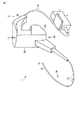
以下、本発明の第1の実施の形態を図1乃至図3を参照して説明する。図1は本実施の形態の工業用内視鏡装置1全体の概略構成を示すものである。図1に示すように本実施の形態の内視鏡装置1は、挿入部20の先端部21に撮像素子(不図示)を内蔵したバッテリ駆動型の例えば工業用内視鏡(以下、内視鏡と略記する)2と、この内視鏡2に接続された装置本体4とで主に構成されている。装置本体4は、内視鏡2の観察部位を照明する照明光を供給する光源部及び撮像素子の駆動及びこの撮像素子から出力される画像信号から映像信号を生成する画像処理部及び、この画像処理部から出力される映像信号を得て内視鏡画像を表示する表示装置であるモニタ3などを備えている。
[First Embodiment]
(Constitution)
Hereinafter, a first embodiment of the present invention will be described with reference to FIGS. FIG. 1 shows a schematic configuration of the entire industrial endoscope apparatus 1 according to the present embodiment. As shown in FIG. 1, an endoscope apparatus 1 according to the present embodiment is a battery-driven industrial endoscope (hereinafter referred to as an endoscope) including an imaging element (not shown) built in a
内視鏡2は、細長で可撓性を有する挿入部20と、この挿入部20の基端部に連設する操作部24と、この操作部24から延出する可撓性を有するユニバーサルコード26とで構成されている。ユニバーサルコード26内には照明光を供給するライトガイドファイバー(不図示)や、撮像素子の駆動制御信号、或いはこの撮像素子で光電変換した画像信号の授受を行う信号ケーブル(不図示)等が内挿されている。
The
挿入部20は、先端側から順に先端部21と、例えば上下/左右方向に湾曲するように構成した湾曲部22と、柔軟性を有する可撓管部23とで構成されている。先端部21の先端面には図示は省略するが、観察窓、照明窓、鉗子導出口、送水や送気用の噴射ノズル等が設けられている。
The
図2に示すように操作部24は、挿入部20の挿入軸の延出方向に延設されたベース部24aと、このベース部24aの延設方向とほぼ直交する方向に突出された突設部24bと、この突設部24bの突出端部(図2中で上端部)に一端が連結された把持部25とが設けられている。把持部25は、挿入部20の挿入軸と異なる軸を有する。
As shown in FIG. 2, the
突設部24bの端面(図2中で上端面)には、湾曲部22を湾曲動作させる湾曲操作を指示入力する湾曲操作部31が設けられている。また、把持部25の後端部には、ユニバーサルコード26の一端が接続されている。このユニバーサルコード26の他端は、装置本体4に電気的に接続されている。
A bending
湾曲操作部31は、操作指示手段であるジョイスティック型の操作部材32を有する。操作部材32は、湾曲部22の湾曲操作を傾倒方向及び傾倒角度を変化させる操作軸32aの基端側が軸受け40に固設されている。軸受け40は、操作部24を構成するフレーム38に回動中心Oを中心に回動自在に設けられている。そして、操作部材32は、操作軸32aの傾倒操作(操作軸32aの傾倒方向及び傾倒角度を変化させる操作)を行うことによって、後述する牽引部材を移動させて湾曲部22を所望の方向に所望の湾曲量だけ湾曲させるようになっている。なお、図2および図3に示すように操作部材32が直立状態のとき湾曲部22は直線状態になるように構成されている。
The bending
湾曲部22は、複数の湾曲駒22a、…、22nを連設して構成されている。先端部21を構成する先端硬質部材21aに連結されるこの湾曲部22の最先端の湾曲駒22aには、例えば、上下/左右の操作方向にそれぞれ対応する牽引部材である4本の操作ワイヤ33の先端部がそれぞれ所定位置に固定されている。
The bending
図2に示すように本実施形態の湾曲装置30は、上記4本の操作ワイヤ33と、これらワイヤ33の中途部がそれぞれ巻回配置される周方向溝34aを有するプーリー34と、このプーリー34を湾曲操作時所定方向に所定トルクで回転させる駆動手段であるモータ35と、操作部材32の下端部に設けられたアーム部36とで主に構成されている。アーム部36には、ワイヤ33の基端部が固定される4つのワイヤ固定部(牽引部材固定部)36aが設けられている。
As shown in FIG. 2, the bending
4本の操作ワイヤ33は、挿入部20内に挿通配置されているワイヤ挿通管路33A内に挿通されて操作部24内まで延出され、プーリー34に巻回されている。そして、巻回された操作ワイヤ33の基端部は、アーム部36の4つのワイヤ固定部36aにそれぞれワイヤ止め33bによって一体的に固定されている。
The four
操作ワイヤ33の中途部は、周方向溝34aに対して所定の弛緩状態で巻回配置されている。また、プーリー34は、モータ35の駆動力を伝達する第1歯車37a、第2歯車37bによって回転されるようになっている。
また、操作部材32の基端側には、アーム部36の下側に略半球状の下側接触部52aが設けられている。フレーム38には、軸受け40を操作部材32とは反対側から回動自在に支持する第1の支え部54を保持する保持板53が設けられている。アーム部36の下側接触部52aと接触する第1の支え部54の接触面には、アーム部36の下側接触部52aと対応する半球状の凹曲面が形成されている。
A midway portion of the
Further, a substantially hemispherical
さらに、フレーム38には、図3中で軸受け40の上側に軸受け40の回転中心Oを中心とした所定半径の半球面を有する半球形状のガイド面38aと、軸受け40を第1の支え部54とは反対側から回動自在に支持する第2の支え部38bとが形成されている。
Further, the
操作部材32のアーム部36の上側には、略半球状の上側接触部52bが設けられている。さらに、操作部材32のアーム部36の外周部位にはOリング39などの弾性体の摩擦部材が装着されている。このOリング39は、フレーム38のガイド面38aに圧接された状態で取り付けられている。
A substantially hemispherical
そして、操作部材32の軸受け40は、アーム部36の下側接触部52aが第1の支え部54と接触し、アーム部36の上側接触部52bが第2の支え部38bと接触することで、第1の支え部54と第2の支え部38bとの間で挟まれた状態で、回動中心Oを中心に回動自在に支持されている。このとき、操作部材32のアーム部36のOリング39は、フレーム38のガイド面38aに圧接されている。これにより、フレーム38のガイド面38aにアーム部36のOリング39を圧接させた際の摩擦力で、傾倒操作される操作部材32の操作軸32aの傾倒操作位置を保持して湾曲部22の湾曲状態を維持する摩擦力保持部50が設けられている。
In the
ここで、操作部材32の操作軸32aは、軸受け40の回転中心Oを中心にX,Y方向それぞれに回動可能である。そして、例えば、操作部材32の回動中心Oを中心に操作部材32を任意の回動位置で停止した際に、摩擦力保持部50のフレーム38のガイド面38aとアーム部36のOリング39との間の摩擦力で、操作部材32をその停止状態で保持することができる。
Here, the
なお、保持板53には、ワイヤ33の数に応じた数(4つ)のワイヤ挿通孔55が形成されており、各挿通孔55には、ワイヤ33を移動可能に挿通するガイド部材56が設けられている。
(作用)
次に、上記構成の作用について説明する。本実施の形態の工業用内視鏡装置1は、図2および図3に示すように湾曲操作部31の操作部材32が直立状態のとき湾曲部22は直線状態になるように構成されている。そして、湾曲操作部31の操作部材32の傾倒操作(操作軸32aの傾倒方向及び傾倒角度を変化させる操作)を行うことによって、湾曲部22を遠隔的に湾曲操作させることにより、挿入部20の先端部21の観察方向を任意の方向に向ける操作が行われる。
The holding
(Function)
Next, the operation of the above configuration will be described. As shown in FIGS. 2 and 3, the industrial endoscope apparatus 1 of the present embodiment is configured such that the bending
ここで、操作部材32が直立状態から傾倒操作された場合には、操作軸32aは、軸受け40の回転中心Oを中心として直立状態の位置から任意の方向に任意の角度に傾動させた操作位置まで傾動される。この場合には、4つのワイヤ固定部36aのうち特定のワイヤ固定部36aが保持板53から離れる方向に移動するとともに、他のワイヤ固定部36aが保持板53に近づく方向に移動する。ここで、ワイヤ固定部36aが保持板53から離れる方向に移動すると、このワイヤ固定部36aに保持されているワイヤ33が引っ張られることになる。また、ワイヤ固定部36aが保持板53に近づく方向に移動すると、このワイヤ固定部36aに保持されているワイヤ33が弛むことになる。このため、4つのワイヤ33のうち、特定のワイヤ33が引っ張られるとともに、他のワイヤ33が弛められると、湾曲部22は、4つのワイヤ33の引っ張り状態及び弛み状態に応じて、所定の方向に湾曲操作される。これにより、挿入部20の先端部21の観察方向を変更することができる。
Here, when the
また、本実施の形態の湾曲操作部31の操作部材32は、摩擦力保持部50によってフレーム38のガイド面38aにアーム部36のOリング39を圧接させた際の摩擦力で、傾倒操作される操作部材32の操作軸32aの傾倒操作位置を保持して湾曲部22の湾曲状態を維持される。したがって、湾曲操作部31の操作部材32を傾倒させた状態で操作部材32より手を離しても操作軸32aが動かず、操作軸32aは手を離す直前の傾倒状態を保持することができる。
In addition, the
さらに、操作部材32の操作軸32aの傾倒操作状態では、湾曲操作部31の操作部材32を摩擦力保持部50の摩擦力以上の力で操作すれば、保持状態のまま湾曲操作部31の操作部材32を動かすことができる。これにより、観察位置の微調整を簡単に行うことができる。
Further, in the tilting operation state of the
(効果)
そこで、上記構成のものにあっては次の効果を奏する。すなわち、本実施の形態の内視鏡装置1では、湾曲操作部31にフレーム38のガイド面38aにアーム部36のOリング39を圧接させた際の摩擦力によって湾曲操作部31の操作部材32の操作位置を保持する摩擦力保持部50を設けている。そのため、従来の湾曲操作部のように操作軸の基端側に設けた曲面状の摩擦部材にストッパ部材を押し当てるための付勢力を発生させるためにばね部材を使用する場合に比べて湾曲操作部31の構成を簡素化することができる。したがって、湾曲操作部31の部品点数を減らして湾曲操作部31全体を小型化するうえで有利となり、製造コストを低減することができる内視鏡の湾曲操作装置を提供することができる。
(effect)
Therefore, the above configuration has the following effects. That is, in the endoscope apparatus 1 of the present embodiment, the
[第1の開示例]
(構成)
図4および図5は、第1の開示例を示す。本開示例は、第1の実施の形態(図1乃至図3参照)のようにアーム部36のOリング39をフレーム38のガイド面38aに圧接させた際の摩擦力によって湾曲操作部31の操作部材32の操作位置を保持する摩擦力保持部50とは異なる構成の摩擦力保持部60を設けたものである。なお、図4および図5中で、図1乃至図3と同一部分には同一の符号を付してその説明を省略する。
[First Disclosure Example]
(Constitution)
4 and 5 show a first disclosed example. In the present disclosure example, the bending
本開示例の摩擦力保持部60は、図4に示すように保持板53のガイド部材56の内周面に弾性体の円管部材(摩擦部材)61を設けたものである。この円管部材61の内径は、操作ワイヤ33の外径よりも小径に設定されている。そして、ガイド部材56の内部に操作ワイヤ33を挿通させた際に、ガイド部材56の内部の円管部材61と操作ワイヤ33との間で摩擦力を発生させる。これにより、ガイド部材56と操作ワイヤ33との接触部位間で円管部材61を圧接させた際の摩擦力で、傾倒操作される操作部材32の操作軸32aの傾倒操作位置を保持して湾曲部22の湾曲状態を維持する構成にしたものである。
As shown in FIG. 4, the friction force holding unit 60 according to the present disclosure includes an elastic circular tube member (friction member) 61 on the inner peripheral surface of the
(作用・効果)
上記構成では、ガイド部材56と操作ワイヤ33との接触部位間で円管部材61を圧接させた際の摩擦力で、傾倒操作される操作部材32の操作軸32aの傾倒操作位置を保持して湾曲部22の湾曲状態を維持する摩擦力保持部60を設けたので、従来の湾曲操作部のように操作軸の基端側に設けた曲面状の摩擦部材にストッパ部材を押し当てるための付勢力を発生させるためにばね部材を使用する場合に比べて湾曲操作部31の構成を簡素化することができる。したがって、湾曲操作部31の部品点数を減らして湾曲操作部31全体を小型化するうえで有利となり、製造コストを低減することができる内視鏡の湾曲操作装置を提供することができる。
(Action / Effect)
In the above configuration, the tilting operation position of the operating
なお、上記開示例では、ガイド部材56の内周面に弾性体の円管部材61を設けた構成を示したが、これに限定されるものではない。例えば、操作ワイヤ33の外周面に弾性体の摩擦部材を貼り付ける構成にしてもよい。さらに、ガイド部材56の内周面に弾性体の円管部材61を設け、かつ操作ワイヤ33の外周面に弾性体の摩擦部材を貼り付ける構成にしてもよい。
In the above disclosed example, the configuration in which the elastic
[第2の開示例]
(構成)
図6および図7は、第2の開示例を示す。本開示例は、第1の実施の形態(図1乃至図3参照)の内視鏡装置1の湾曲操作部31とは異なる構成の湾曲操作部71を設けたものである。なお、図6および図7中で、図1乃至図3と同一部分には同一の符号を付してその説明を省略する。
[Second Disclosure Example]
(Constitution)
6 and 7 show a second disclosed example. In the present disclosure example, a bending
本開示例の湾曲操作部71は、操作部材32のアーム部36の下側に軸状の摩擦部材72を有する。この摩擦部材72の端面(図6中で下端面)には、平面からなる当接面73が形成されている。
また、フレーム38の保持板53には、操作部材32の摩擦部材72の基端部と当接するストッパ部材74と、このストッパ部材74を摩擦部材72の基端部に当接する方向に付勢するばね部材(付勢手段)75とが設けられている。ストッパ部材74の端面(図6中で上端面)には、平面からなる突き当て面76が形成されている。そして、ストッパ部材74と摩擦部材72の基端部と当接部の摩擦力で、傾倒操作される操作部材32の傾倒操作位置を保持して湾曲部22の湾曲状態を維持する摩擦力保持部77が設けられている。
The bending
Further, the holding
(作用)
次に、上記構成の作用について説明する。本開示例の湾曲操作部71では、操作部材32が直立状態で保持されている場合には、図7(A)に示すように操作部材32の摩擦部材72の当接面73と、ストッパ部材74の突き当て面76とが平面同士の面接触状態で保持されている。そのため、この状態では、操作部材32の摩擦部材72の当接面73と、ストッパ部材74の突き当て面76との接触面の面積が大きいので、操作部材32の摩擦部材72の当接面73と、ストッパ部材74の突き当て面76との接触面間には比較的大きな摩擦力が作用する。その結果、操作部材32が直立状態で保持されている場合には、摩擦力保持部77によって操作部材32が直立状態で安定に保持される。
(Function)
Next, the operation of the above configuration will be described. In the
また、操作部材32が直立状態から傾倒操作された場合には、操作軸32aは、軸受け40の回転中心Oを中心として直立状態の位置から任意の方向に任意の角度に傾動させた操作位置まで傾動される。この場合には、図7(B)に示すように操作部材32の摩擦部材72の当接面73が一端部を支点として傾斜するので、ストッパ部材74の突き当て面76と操作部材32の摩擦部材72の当接面73との接触部位は、線接触状態、あるいは点接触状態に切り替わる。そのため、この状態では、操作部材32が直立状態で保持されている場合に比べて操作部材32の摩擦部材72の当接面73と、ストッパ部材74の突き当て面76との接触面間の面積が小さくなるので、操作部材32の摩擦部材72の当接面73と、ストッパ部材74の突き当て面76との接触面間に作用する摩擦力は小さくなる。その結果、操作部材32が傾倒操作された場合には、摩擦力保持部77によって操作部材32の傾倒操作位置を保持して湾曲部22の湾曲状態を維持する力の大きさが小さくなる。
Further, when the
したがって、本開示例では、操作部材32が直立状態で保持されている場合と、操作部材32が直立状態から傾倒操作された場合とで、操作部材32を操作する操作者の操作感などの感触が変化するので、操作部材32が直立状態で保持されている場合と、操作部材32が直立状態から傾倒操作された場合との違いを操作部材32を操作する操作者の操作感などの感触の違いで判別することができる。
Therefore, in the present disclosure, a feeling such as an operation feeling of an operator who operates the
(効果)
そこで、上記構成のものにあっては次の効果を奏する。すなわち、本開示例の内視鏡装置1の湾曲操作部71では、操作部材32のアーム部36の軸状の摩擦部材72の端面に、平面からなる当接面73を形成し、フレーム38の保持板53のストッパ部材74の端面に、平面からなる突き当て面76を形成している。そのため、操作部材32が直立状態で保持されている場合と、操作部材32が直立状態から傾倒操作された場合とで、操作部材32を操作する操作者の操作感などの感触が変化するので、操作部材32が直立状態で保持されている場合と、操作部材32が直立状態から傾倒操作された場合との違いを操作部材32を操作する操作者の操作感などの感触の違いで判別することができる効果がある。
(effect)
Therefore, the above configuration has the following effects. That is, in the
[第3の開示例]
(構成)
図8(A),(B)は、第3の開示例を示す。本開示例は、第2の開示例(図6および図7参照)の変形例である。すなわち、本開示例では、操作部材32の摩擦部材72の端面(図8中で下端面)に、2つの平面からなる当接面81,82が形成されている。2つの当接面81,82はそれぞれ摩擦部材72の中心線L1に対してほぼ45°の角度で交差する傾斜面によって形成されている。
[Third Disclosure Example]
(Constitution)
8A and 8B show a third disclosed example. The present disclosure example is a modification of the second disclosure example (see FIGS. 6 and 7). That is, in the present disclosure example, the contact surfaces 81 and 82 composed of two planes are formed on the end surface (the lower end surface in FIG. 8) of the
(作用)
次に、上記構成の作用について説明する。本開示例の湾曲操作部71では、操作部材32が直立状態で保持されている場合には、図8(A)に示すように操作部材32の摩擦部材72の2つの当接面81,82間の交点の部分がストッパ部材74の突き当て面76と線接触状態、あるいは点接触状態の接触状態で保持されている。そのため、この状態では、操作部材32の摩擦部材72と、ストッパ部材74の突き当て面76との接触面間の面積が小さくなるので、操作部材32の摩擦部材72と、ストッパ部材74の突き当て面76との接触面間に作用する摩擦力は小さくなる。その結果、操作部材32が直立状態で保持されている場合には、摩擦力保持部77によって操作部材32の操作位置を保持して湾曲部22の湾曲状態を維持する力の大きさが小さくなる。
(Function)
Next, the operation of the above configuration will be described. In the
これに対し、操作部材32が直立状態から傾倒操作され、例えば、図8(B)に示すように操作部材32の摩擦部材72の2つの当接面81,82のいずれか一方、本開示例では摩擦部材72の一方の当接面82がストッパ部材74の突き当て面76と平面同士の面接触状態に切替えられた場合には、操作部材32の摩擦部材72の一方の当接面82と、ストッパ部材74の突き当て面76との接触面の面積が大きいので、操作部材32の摩擦部材72の当接面82と、ストッパ部材74の突き当て面76との接触面間には比較的大きな摩擦力が作用する。その結果、操作部材32が例えば、最大傾倒位置まで傾倒された状態で保持されている場合には、摩擦力保持部77によって操作部材32が最大傾倒状態で安定に保持される。
On the other hand, the
したがって、本開示例でも、操作部材32が直立状態で保持されている場合と、操作部材32が直立状態から最大傾倒状態まで傾倒操作された場合とで、操作部材32を操作する操作者の操作感などの感触が変化するので、操作部材32が直立状態で保持されている場合と、操作部材32が直立状態から最大傾倒状態まで傾倒操作された場合との違いを操作部材32を操作する操作者の操作感などの感触の違いで判別することができる。
Therefore, also in the present disclosure, the operation of the operator who operates the
(効果)
そこで、上記構成のものにあっては次の効果を奏する。すなわち、本開示例の内視鏡装置1の湾曲操作部71では、操作部材32のアーム部36の軸状の摩擦部材72の端面に、平面からなる2つの当接面81,82を形成し、フレーム38の保持板53のストッパ部材74の端面に、平面からなる突き当て面76を形成している。そのため、操作部材32が直立状態で保持されている場合と、操作部材32が直立状態から最大傾倒状態まで傾倒操作された場合とで、操作部材32を操作する操作者の操作感などの感触が変化するので、操作部材32が直立状態で保持されている場合と、操作部材32が直立状態から最大傾倒状態まで傾倒操作された場合との違いを操作部材32を操作する操作者の操作感などの感触の違いで判別することができる効果がある。
(effect)
Therefore, the above configuration has the following effects. That is, in the
なお、上記開示例では、操作部材32の摩擦部材72の端面に、1つの平面からなる当接面73または2つの平面からなる当接面81,82を設けた例を示したが、当接面の数は、3以上の複数であってもよい。
[第4の開示例]
(構成)
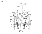
図9は、第4の開示例を示す。本開示例は、第1の実施の形態(図1乃至図3参照)の内視鏡装置1の湾曲操作部31とは異なる構成の湾曲操作部91を設けたものである。なお、図9中で、図1乃至図3と同一部分には同一の符号を付してその説明を省略する。
In the above disclosed example, an example in which the
[Fourth Disclosure Example]
(Constitution)
FIG. 9 shows a fourth disclosed example. In the present disclosure example, a bending
本開示例の湾曲操作部91は、湾曲部22の湾曲状態を維持する摩擦力保持部92の構成が第1の実施の形態とは異なる。本開示例の摩擦力保持部92は、操作部材32の軸受け40の回転中心Oを中心とした所定半径の半球面を有する半球形状の摩擦部材93と、この摩擦部材93の所定半径に対して摺動する面を形成したストッパ部材94と、を具備する。摩擦部材93は、摩擦部材93の回転中心Oに対して操作部材32の先端部側に凹む半球状のガイド面95を有する。
The bending
ストッパ部材94は、摩擦部材93のガイド面95と当接する当接部材96と、この当接部材96をガイド面95に当接する方向に付勢するばね部材(付勢手段)97とを有する。そして、本開示例の摩擦力保持部92は、ストッパ部材94の当接部材96と摩擦部材93のガイド面95との摩擦力で、傾倒操作される操作部材32の傾倒操作位置を保持して湾曲部22の湾曲状態を維持する構成になっている。
The
(効果)
上記構成のものにあっては次の効果を奏する。すなわち、本開示例の湾曲操作部91では、摩擦部材93の回転中心Oに対して操作部材32の先端部側に凹む半球状のガイド面95を摩擦部材93の内面に設け、この凹曲面状のガイド面95にストッパ部材94の当接部材96を当接させている。そのため、本開示例の湾曲操作部91では、摩擦部材93の内面に凹曲面状のガイド面95が形成されていない場合に比べて湾曲操作部91のユニット全体の高さを低くすることができる。その結果、湾曲操作部91のユニット全体の小型化を図ることができる。
(effect)
The above configuration has the following effects. That is, in the
[第5の開示例]
(構成)
図10および図11(A),(B)は、第5の開示例を示す。本開示例は、第1の実施の形態(図1乃至図3参照)の内視鏡装置1の湾曲操作部31とは異なる構成の湾曲操作部101を設けたものである。なお、図10および図11(A),(B)中で、図1乃至図3と同一部分には同一の符号を付してその説明を省略する。
[Fifth Disclosure Example]
(Constitution)
10 and FIGS. 11A and 11B show a fifth disclosed example. In the present disclosure, a bending
本開示例の湾曲操作部101は、ジョイスティック型の操作部材32の操作軸32aの基端部に第1の回動軸102が固設されている。第1の回動軸102は、第1の軸支部103によって操作部材32の操作軸32aの軸心方向と直交する方向(X方向)の回転中心を中心に回動可能に軸支されている。第1の軸支部103は、リング状の2つの軸支部構成体103a、103bを有する。2つの軸支部構成体103a、103bは、第1の回動軸102の両側から第1の回動軸102にそれぞれ嵌め込まれる。また、2つの軸支部構成体103a、103bの内端面には、操作軸32aと嵌合する長溝状の凹部103a1,103b1がそれぞれ形成されている。そして、2つの軸支部構成体103a、103bを第1の回動軸102の両側から第1の回動軸102にそれぞれ嵌め込んで組み付けた際に、2つの軸支部構成体103a、103bの凹部103a1,103b1間に操作軸32aが嵌合される状態で組み付けられるようになっている。
In the
また、第1の軸支部103の外周面には、第1の回動軸102の軸心方向と直交する方向(Y方向)に延設された2つの第2の回動軸104が設けられている。ここで、第1の軸支部103の一側面には、一方の第2の回動軸104、第1の軸支部103の他側面には、他方の第2の回動軸104がそれぞれ配置されている。
In addition, two second
また、2つの第2の回動軸104は、それぞれ円柱状の軸を2つに切断した2つの回動軸構成体104a、104bを有する。一方の軸支部構成体103aには、2つの回動軸構成体104a、104aが固定され、他方の軸支部構成体103bには、2つの回動軸構成体104b、104bが固定されている。そして、2つの軸支部構成体103a、103bと第1の回動軸102との組み付け時には、2つの回動軸構成体104a、104b間が接合されて2つの第2の回動軸104が形成されるようになっている。
The two second
2つの第2の回動軸104は、リング状の第2の軸支部105がそれぞれ嵌め込まれている。そして、第2の回動軸104は、第2の軸支部105によって第1の回動軸102の回動方向(X方向)と直交するY方向の回転中心を中心に回動可能に軸支されている。
Two second
また、第1の回動軸102と第1の軸支部103との間には、円管状の弾性体の摩擦部材(第1の摩擦力発生手段)106が介設されている。この摩擦部材106によって第1の回動軸102と第1の軸支部103との間に摩擦力を発生させるようになっている。さらに、第2の回動軸104と第2の軸支部105との間には、円管状の弾性体の摩擦部材(第2の摩擦力発生手段)107が介設されている。この摩擦部材107によって第2の回動軸104と第2の軸支部105との間に摩擦力を発生させるようになっている。そして、第1の回動軸102と第1の軸支部103との間の摩擦部材106および第2の回動軸104と第2の軸支部105との間の摩擦部材107の摩擦力で、傾倒操作される操作部材32の操作軸32aの傾倒操作位置を保持して湾曲部22の湾曲状態を維持する摩擦力保持部108が設けられている。
Further, a circular elastic friction member (first frictional force generating means) 106 is interposed between the first
(効果)
上記構成のものにあっては次の効果を奏する。すなわち、本開示例の湾曲操作部101では、第1の回動軸102と第1の軸支部103との間の摩擦部材106および第2の回動軸104と第2の軸支部105との間の摩擦部材107の摩擦力で、傾倒操作される操作部材32の操作軸32aの傾倒操作位置を保持して湾曲部22の湾曲状態を維持する摩擦力保持部108を設けている。そのため、本開示例の湾曲操作部101では、従来の湾曲操作部のように操作軸の基端側に設けた曲面状の摩擦部材にストッパ部材を押し当てるための付勢力を発生させるためにばね部材を省略することができる。
(effect)
The above configuration has the following effects. That is, in the
さらに、本発明は上記実施の形態に限定されるものではなく、本発明の要旨を逸脱しない範囲で種々変形実施できることは勿論である。
次に、本出願の他の特徴的な技術事項を下記の通り付記する。
記
(付記項1) 細長な挿入部の先端側に設けられた湾曲自在な湾曲部の湾曲操作を傾倒方向及び傾倒角度を変化させる傾倒操作によって行う、前記挿入部の基端部に連設する操作部を構成するフレームに回動自在に設けられた軸受けに基端側が固設され当該軸受けの回転中心点に対して所定の方向に回動可能な、先端側が当該操作部の外部に突出して設けられた操作指示手段と、先端部が前記湾曲部の所定位置に固定され、基端部が前記操作指示手段の基端側であって、前記軸受けを挟んで設けられたアーム部材が有する複数のアーム部に固定された、前記操作指示手段の傾倒操作によって移動されて前記湾曲部を湾曲させる牽引部材と、を具備する内視鏡において、前記フレームに前記牽引部材を移動可能に挿通するガイド部材を設け、前記ガイド部材と前記牽引部材との接触部位間の少なくともいずれか一方に弾性体の摩擦部材を設け、前記ガイド部材と前記牽引部材との接触部位間で前記摩擦部材を圧接させた際の摩擦力で、傾倒操作される前記操作指示手段の傾倒操作位置を保持して前記湾曲部の湾曲状態を維持する摩擦力保持部を設けたことを特徴とする内視鏡。
Furthermore, the present invention is not limited to the above-described embodiment, and various modifications can be made without departing from the scope of the present invention.
Next, other characteristic technical matters of the present application are appended as follows.
Record
(Additional Item 1) An operation connected to the proximal end portion of the insertion portion, wherein the bending operation of the bendable bending portion provided on the distal end side of the elongated insertion portion is performed by a tilting operation that changes a tilt direction and a tilt angle. A base end side is fixed to a bearing that is rotatably provided on a frame that constitutes the portion, and is rotatable in a predetermined direction with respect to the rotation center point of the bearing. A plurality of arm members provided on both sides of the bearing, the distal end portion being fixed at a predetermined position of the bending portion, the proximal end portion being the proximal end side of the operation instruction portion, A guide member that is fixed to an arm portion and that is moved by a tilting operation of the operation instruction means to bend the bending portion; and a guide member that movably inserts the pulling member into the frame Provided An elastic friction member is provided in at least one of the contact portions between the guide member and the traction member, and the friction force when the friction member is pressed between the contact portions between the guide member and the traction member. An endoscope comprising a frictional force holding portion that holds a tilting operation position of the operation instruction means that is tilted and maintains the bending state of the bending portion.
(付記項2) 細長な挿入部の先端側に設けた湾曲自在な湾曲部の湾曲操作を指示入力する湾曲操作部が前記挿入部の基端部に連設する操作部に設けられ、先端部が前記湾曲部の所定位置に固定された牽引部材の基端部が前記湾曲操作部に固定され、前記湾曲操作部の操作によって前記牽引部材を介して前記湾曲部を湾曲させる内視鏡の湾曲操作装置において、前記湾曲操作部は、前記湾曲部の湾曲操作を傾倒方向及び傾倒角度を変化させる操作軸の傾倒操作によって行う操作指示手段と、前記操作軸の基端側が固設された第1の回動軸と、前記第1の回動軸の軸心を中心に前記第1の回動軸を回動可能に軸支する第1の軸支部と、前記第1の軸支部に設けられ、前記第1の回動軸の軸心方向と直交する方向に延設された第2の回動軸と、前記第2の回動軸の軸心を中心に前記第2の回動軸を回動可能に軸支する第2の軸支部と、前記第1の回動軸と前記第1の軸支部との間に介設され、前記第1の回動軸と前記第1の軸支部との間に摩擦力を発生させる第1の摩擦力発生手段と、前記第2の回動軸と前記第2の軸支部との間に介設され、前記第2の回動軸と前記第2の軸支部との間に摩擦力を発生させる第2の摩擦力発生手段と、を具備し、前記第1の摩擦力発生手段および前記第2の摩擦力発生手段の摩擦力で、傾倒操作される前記操作指示手段の前記操作軸の傾倒操作位置を保持して前記湾曲部の湾曲状態を維持する摩擦力保持部を設けたことを特徴とする内視鏡の湾曲操作装置。 (Additional Item 2) A bending operation unit that inputs and inputs a bending operation of a bendable bending portion provided on the distal end side of the elongated insertion portion is provided in an operation portion that is provided continuously with a proximal end portion of the insertion portion. A bending of an endoscope in which a base end portion of a traction member fixed at a predetermined position of the bending portion is fixed to the bending operation portion, and the bending portion is bent via the traction member by operation of the bending operation portion. In the operating device, the bending operation section includes a first operation instruction unit that performs a bending operation of the bending section by a tilting operation of an operation shaft that changes a tilt direction and a tilt angle, and a base end side of the operation shaft is fixedly provided. Provided on the first shaft support portion, a first shaft support portion for pivotally supporting the first rotation shaft about the axis of the first rotation shaft, and the first shaft support portion. A second rotation shaft extending in a direction orthogonal to the axial direction of the first rotation shaft, and the front A second shaft supporting portion that pivotally supports the second rotating shaft about the axis of the second rotating shaft, and the first rotating shaft and the first shaft supporting portion. A first friction force generating means interposed between the first rotation shaft and the first shaft support portion; the second rotation shaft; and the second rotation shaft. A second frictional force generating means that is interposed between the second pivot shaft and the second pivot shaft, and generates a frictional force between the second pivot shaft and the second pivotal support portion. Friction force holding for maintaining the bending state of the bending portion by holding the tilting operation position of the operation shaft of the operation instruction means to be tilted by the frictional force of the frictional force generating means and the second frictional force generating means Endoscope bending operation device characterized in that a section is provided.
(付記項3) 細長な挿入部の先端側に設けられた湾曲自在な湾曲部の湾曲操作を傾倒方向及び傾倒角度を変化させる傾倒操作によって行う、前記挿入部の基端部に連設する操作部を構成するフレームに回動自在に設けられた軸受けに基端側が固設され当該軸受けの回転中心点に対して所定の方向に回動可能な、先端側が当該操作部の外部に突出して設けられた操作指示手段と、先端部が前記湾曲部の所定位置に固定され、基端部が前記操作指示手段の基端側であって、前記軸受けを挟んで設けられたアーム部材が有する複数のアーム部に固定された、前記操作指示手段の傾倒操作によって移動されて前記湾曲部を湾曲させる牽引部材と、を具備する内視鏡において、前記操作指示手段は、前記湾曲部の湾曲操作を傾倒方向及び傾倒角度を変化させる操作軸を有し、前記操作軸の基端部は、少なくとも1つの平面からなる当接面を有し、前記軸受けは、前記操作軸の基端部と当接するストッパ部材と、前記ストッパ部材を前記操作軸の基端部に当接する方向に付勢する付勢手段とを有し、前記ストッパ部材と前記操作軸の基端部との摩擦力で、傾倒操作される前記操作指示手段の前記操作軸の傾倒操作位置を保持して前記湾曲部の湾曲状態を維持する摩擦力保持部を設けたことを特徴とする内視鏡。 (Additional Item 3) An operation connected to the proximal end portion of the insertion portion, wherein the bending operation of the bendable bending portion provided on the distal end side of the elongated insertion portion is performed by a tilting operation that changes the tilting direction and the tilting angle. A base end side is fixed to a bearing that is rotatably provided on a frame that constitutes the portion, and is rotatable in a predetermined direction with respect to the rotation center point of the bearing. A plurality of arm members provided on both sides of the bearing, the distal end portion being fixed at a predetermined position of the bending portion, the proximal end portion being the proximal end side of the operation instruction portion, An endoscope having a pulling member that is fixed to an arm portion and is moved by a tilting operation of the operation instruction unit to bend the bending unit, wherein the operation instruction unit tilts the bending operation of the bending unit Change direction and tilt angle An operation shaft to be operated, and a base end portion of the operation shaft has an abutting surface including at least one plane, and the bearing includes a stopper member that contacts the base end portion of the operation shaft, and the stopper member Urging means that urges the operation shaft in a direction in contact with the base end portion of the operation shaft, and the operation instruction means is tilted by a frictional force between the stopper member and the base end portion of the operation shaft. An endoscope comprising a frictional force holding portion that holds a tilting operation position of the operation shaft and maintains a bending state of the bending portion.
(付記項4) 細長な挿入部の先端側に設けられた湾曲自在な湾曲部の湾曲操作を傾倒方向及び傾倒角度を変化させる傾倒操作によって行う、前記挿入部の基端部に連設する操作部を構成するフレームに回動自在に設けられた軸受けに基端側が固設され当該軸受けの回転中心点に対して所定の方向に回動可能な、先端側が当該操作部の外部に突出して設けられた操作指示手段と、先端部が前記湾曲部の所定位置に固定され、基端部が前記操作指示手段の基端側であって、前記軸受けを挟んで設けられたアーム部材が有する複数のアーム部に固定された、前記操作指示手段の傾倒操作によって移動されて前記湾曲部を湾曲させる牽引部材と、を具備する内視鏡において、前記操作指示手段の軸受けの回転中心を中心とした所定半径の半球面を有する半球形状の摩擦部材と、前記摩擦部材の所定半径に対して摺動する面を形成したストッパ部材と、を具備し、前記摩擦部材は、前記摩擦部材の回転中心に対して前記操作指示手段の先端部側に凹む半球状のガイド面を有し、前記ストッパ部材は、前記ガイド面と当接する当接部材と、前記当接部材を前記ガイド面に当接する方向に付勢する付勢手段とを有し、前記ストッパ部材の前記当接部材と前記摩擦部材のガイド面との摩擦力で、傾倒操作される前記操作指示手段の傾倒操作位置を保持して前記湾曲部の湾曲状態を維持する摩擦力保持部を設けたことを特徴とする内視鏡。 (Additional Item 4) An operation that is connected to the proximal end portion of the insertion portion, wherein the bending operation of the bendable bending portion provided on the distal end side of the elongated insertion portion is performed by a tilting operation that changes the tilting direction and the tilting angle. A base end side is fixed to a bearing that is rotatably provided on a frame that constitutes the portion, and is rotatable in a predetermined direction with respect to the rotation center point of the bearing. A plurality of arm members provided on both sides of the bearing, the distal end portion being fixed at a predetermined position of the bending portion, the proximal end portion being the proximal end side of the operation instruction portion, And a pulling member that is fixed to the arm portion and is moved by a tilting operation of the operation instruction means to bend the bending portion. A predetermined centering on a rotation center of a bearing of the operation instruction means. Has a radius hemisphere A hemispherical friction member, and a stopper member formed with a surface that slides with respect to a predetermined radius of the friction member, and the friction member is operated with respect to a rotation center of the friction member. The stopper member has an abutting member that abuts against the guide surface, and an urging means that urges the abutting member in a direction to abut against the guide surface. And maintaining the bending state of the bending portion by holding the tilt operation position of the operation instruction means tilted by the frictional force between the contact member of the stopper member and the guide surface of the friction member. An endoscope characterized in that a frictional force holding portion is provided.
本発明は、内視鏡の挿入部の先端側に設けられた湾曲部を湾曲させる操作を行う湾曲操作部にジョイスティック型の操作部材が配設された内視鏡の湾曲操作装置を使用する技術分野や、これを製造する技術分野に有効である。 The present invention uses a bending operation device for an endoscope in which a joystick-type operation member is disposed in a bending operation portion that performs an operation for bending a bending portion provided on a distal end side of an insertion portion of an endoscope. It is effective in the field and the technical field for manufacturing it.
20…挿入部、22…湾曲部、24…操作部、31…湾曲操作部、32…操作部材(操作指示手段)、32a…操作軸、33…操作ワイヤ(牽引部材)、38aガイド面、36a…ワイヤ固定部(牽引部材固定部)、38…フレーム、39…Oリング(摩擦部材)、40…軸受け、O…回転中心、50…摩擦力保持部。
DESCRIPTION OF
Claims (4)
先端部が前記湾曲部の所定位置に固定された牽引部材の基端部が前記湾曲操作部に固定され、前記湾曲操作部の操作によって前記牽引部材を介して前記湾曲部を湾曲させる内視鏡の湾曲操作装置において、
前記湾曲操作部は、前記湾曲部の湾曲操作を傾倒方向及び傾倒角度を変化させる操作軸の傾倒操作によって行う操作指示手段と、
前記操作軸の基端側が固設され、前記操作部を構成するフレームに回動自在に設けられた軸受けと、
前記フレームに設けられ、前記軸受けの回転中心を中心とした所定半径の半球面を有する半球形状のガイド面と、
前記牽引部材の基端部を固定する前記湾曲操作部の牽引部材固定部に設けられ、前記ガイド面に圧接される弾性体の摩擦部材と、を具備し、
前記フレームの前記ガイド面に前記摩擦部材を圧接させた際の摩擦力で、傾倒操作される前記操作軸の傾倒操作位置を保持して前記湾曲部の湾曲状態を維持する摩擦力保持部を設けたことを特徴とする内視鏡の湾曲操作装置。 Bending operation portion for inputting an instruction bending operation of the bending portion provided on the distal end side of the insertion portion is provided on the operation unit for continuously arranged on the proximal end of the insertion section,
An endoscope in which a proximal end portion of a traction member having a distal end portion fixed at a predetermined position of the bending portion is fixed to the bending operation portion, and the bending portion is bent via the traction member by operation of the bending operation portion. In the bending operation device of
The bending operation unit includes an operation instruction unit that performs a bending operation of the bending unit by a tilting operation of an operation shaft that changes a tilting direction and a tilting angle;
A base end side of the operation shaft is fixed, and a bearing rotatably provided on a frame constituting the operation unit;
A hemispherical guide surface provided on the frame and having a hemispherical surface with a predetermined radius around the rotation center of the bearing;
An elastic friction member provided at a traction member fixing portion of the bending operation portion that fixes a base end portion of the traction member, and being in pressure contact with the guide surface;
A friction force holding portion is provided that maintains a bending state of the bending portion by holding a tilting operation position of the operation shaft to be tilted by a friction force when the friction member is pressed against the guide surface of the frame. An endoscope bending operation apparatus characterized by the above.
前記操作指示手段は、少なくとも前記牽引部材固定部と前記摩擦部材とが弾性体で一体成形された一体成形体を有する
ことを特徴とする請求項1に記載の内視鏡の湾曲操作装置。 The frame has a resin frame formed of a resin material,
The bending operation apparatus for an endoscope according to claim 1, wherein the operation instructing unit includes an integral molded body in which at least the pulling member fixing portion and the friction member are integrally molded with an elastic body.
前記第1の支え部および前記第2の支え部と前記軸受けとの接触部に摩擦力を発生させながら摺動し、前記湾曲部の湾曲状態を維持する摩擦力保持面を有する
ことを特徴とする請求項1に記載の内視鏡の湾曲操作装置。 The frame includes a first support portion that rotatably supports the bearing from a side opposite to the operation instruction means, and a first support portion that rotatably supports the bearing from a side opposite to the first support portion. 2 support parts,
A friction force holding surface that slides while generating a frictional force at a contact portion between the first support portion and the second support portion and the bearing, and maintains a bending state of the bending portion. The bending operation apparatus for an endoscope according to claim 1.
前記挿入部の先端側に設けられ、前記挿入部を湾曲操作する湾曲部と、
前記挿入部の基端部に連接された操作部と、
前記操作部に設けられ、前記湾曲部の湾曲操作を指示する湾曲操作部と、
を備え、
前記湾曲操作部は、前記湾曲部の湾曲操作を傾倒方向及び傾倒角度を変化させる操作軸の傾倒操作によって行う操作指示手段と、
前記操作軸の基端側が固設され、前記操作部を構成するフレームに回動自在に設けられた軸受けと、
前記フレームに設けられ、前記軸受けの回転中心を中心とした所定半径の半球面を有する半球形状のガイド面と、
前記牽引部材の基端部を固定する前記湾曲操作部の牽引部材固定部に設けられ、前記ガイド面に圧接される弾性体の摩擦部材と、を具備し、
前記フレームの前記ガイド面に前記摩擦部材を圧接させた際の摩擦力で、傾倒操作される前記操作軸の傾倒操作位置を保持して前記湾曲部の湾曲状態を維持する摩擦力保持部を設けたことを特徴とする内視鏡装置。 An insertion part to be inserted into the subject;
A bending portion that is provided on a distal end side of the insertion portion and performs a bending operation on the insertion portion;
An operation unit connected to the proximal end of the insertion unit;
A bending operation unit provided in the operation unit and instructing a bending operation of the bending unit;
With
The bending operation unit includes an operation instruction unit that performs a bending operation of the bending unit by a tilting operation of an operation shaft that changes a tilting direction and a tilting angle;
A base end side of the operation shaft is fixed, and a bearing rotatably provided on a frame constituting the operation unit;
A hemispherical guide surface provided on the frame and having a hemispherical surface with a predetermined radius around the rotation center of the bearing;
An elastic friction member provided at a traction member fixing portion of the bending operation portion that fixes a base end portion of the traction member, and being in pressure contact with the guide surface;
A friction force holding portion is provided that maintains a bending state of the bending portion by holding a tilting operation position of the operation shaft to be tilted by a friction force when the friction member is pressed against the guide surface of the frame. An endoscope apparatus characterized by that.
Priority Applications (1)
| Application Number | Priority Date | Filing Date | Title |
|---|---|---|---|
| JP2010248889A JP5513347B2 (en) | 2010-11-05 | 2010-11-05 | Endoscope bending operation device and endoscope device using the same |
Applications Claiming Priority (1)
| Application Number | Priority Date | Filing Date | Title |
|---|---|---|---|
| JP2010248889A JP5513347B2 (en) | 2010-11-05 | 2010-11-05 | Endoscope bending operation device and endoscope device using the same |
Publications (3)
| Publication Number | Publication Date |
|---|---|
| JP2012100683A JP2012100683A (en) | 2012-05-31 |
| JP2012100683A5 JP2012100683A5 (en) | 2013-12-12 |
| JP5513347B2 true JP5513347B2 (en) | 2014-06-04 |
Family
ID=46391891
Family Applications (1)
| Application Number | Title | Priority Date | Filing Date |
|---|---|---|---|
| JP2010248889A Active JP5513347B2 (en) | 2010-11-05 | 2010-11-05 | Endoscope bending operation device and endoscope device using the same |
Country Status (1)
| Country | Link |
|---|---|
| JP (1) | JP5513347B2 (en) |
Families Citing this family (4)
| Publication number | Priority date | Publication date | Assignee | Title |
|---|---|---|---|---|
| CN105682529B (en) | 2013-11-07 | 2018-05-25 | 奥林巴斯株式会社 | Endoscope |
| JP2016221024A (en) * | 2015-06-01 | 2016-12-28 | オリンパス株式会社 | Endoscope apparatus |
| JP2016221025A (en) * | 2015-06-01 | 2016-12-28 | オリンパス株式会社 | Endoscope apparatus |
| CN114748020B (en) * | 2022-04-22 | 2022-12-06 | 湖南省华芯医疗器械有限公司 | Endoscope butt joint structure, endoscope handle and endoscope |
-
2010
- 2010-11-05 JP JP2010248889A patent/JP5513347B2/en active Active
Also Published As
| Publication number | Publication date |
|---|---|
| JP2012100683A (en) | 2012-05-31 |
Similar Documents
| Publication | Publication Date | Title |
|---|---|---|
| JP4772464B2 (en) | Operating device | |
| JP4616017B2 (en) | Electric bending endoscope device | |
| JP4970870B2 (en) | Endoscope operating device | |
| US9028397B2 (en) | Medical apparatus | |
| JP5583860B2 (en) | Insertion device provided with operation input unit | |
| EP1920701A1 (en) | Medical device | |
| US8961402B2 (en) | Endoscope | |
| JP4813067B2 (en) | Endoscope device | |
| US20130060088A1 (en) | Bending portion-equipped medical apparatus | |
| JPWO2013114913A1 (en) | Insertion device | |
| JP5274727B2 (en) | Endoscope | |
| JP5513347B2 (en) | Endoscope bending operation device and endoscope device using the same | |
| JP4102320B2 (en) | Endoscope | |
| JP2003325437A (en) | Tractive member operating device | |
| JP2009101076A (en) | Tractive member operating device and endoscope apparatus | |
| JP2004321492A (en) | Endoscope | |
| US20160353975A1 (en) | Bending operation mechanism for endoscope | |
| JP5838327B2 (en) | Endoscope | |
| JP4970844B2 (en) | Medical device and torsional force release method | |
| JP4068855B2 (en) | Electric bending endoscope device | |
| JP2012040202A (en) | Manipulator | |
| EP4340692A1 (en) | Endoscope comprising a bending section having a varying length of hinges | |
| JP3181703B2 (en) | Electric curved endoscope device | |
| WO2021070389A1 (en) | Bending operation mechanism for endoscope | |
| JP6250232B1 (en) | Bending operation device and endoscope using the same |
Legal Events
| Date | Code | Title | Description |
|---|---|---|---|
| A521 | Request for written amendment filed |
Free format text: JAPANESE INTERMEDIATE CODE: A523 Effective date: 20131029 |
|
| A621 | Written request for application examination |
Free format text: JAPANESE INTERMEDIATE CODE: A621 Effective date: 20131029 |
|
| A977 | Report on retrieval |
Free format text: JAPANESE INTERMEDIATE CODE: A971007 Effective date: 20140311 |
|
| TRDD | Decision of grant or rejection written | ||
| A01 | Written decision to grant a patent or to grant a registration (utility model) |
Free format text: JAPANESE INTERMEDIATE CODE: A01 Effective date: 20140318 |
|
| A61 | First payment of annual fees (during grant procedure) |
Free format text: JAPANESE INTERMEDIATE CODE: A61 Effective date: 20140327 |
|
| R151 | Written notification of patent or utility model registration |
Ref document number: 5513347 Country of ref document: JP Free format text: JAPANESE INTERMEDIATE CODE: R151 |
|
| S531 | Written request for registration of change of domicile |
Free format text: JAPANESE INTERMEDIATE CODE: R313531 |
|
| R350 | Written notification of registration of transfer |
Free format text: JAPANESE INTERMEDIATE CODE: R350 |
|
| R250 | Receipt of annual fees |
Free format text: JAPANESE INTERMEDIATE CODE: R250 |
|
| R250 | Receipt of annual fees |
Free format text: JAPANESE INTERMEDIATE CODE: R250 |
|
| R250 | Receipt of annual fees |
Free format text: JAPANESE INTERMEDIATE CODE: R250 |
|
| R250 | Receipt of annual fees |
Free format text: JAPANESE INTERMEDIATE CODE: R250 |
|
| S111 | Request for change of ownership or part of ownership |
Free format text: JAPANESE INTERMEDIATE CODE: R313111 |
|
| R371 | Transfer withdrawn |
Free format text: JAPANESE INTERMEDIATE CODE: R371 |
|
| S111 | Request for change of ownership or part of ownership |
Free format text: JAPANESE INTERMEDIATE CODE: R313111 |
|
| R371 | Transfer withdrawn |
Free format text: JAPANESE INTERMEDIATE CODE: R371 |
|
| R250 | Receipt of annual fees |
Free format text: JAPANESE INTERMEDIATE CODE: R250 |
|
| S111 | Request for change of ownership or part of ownership |
Free format text: JAPANESE INTERMEDIATE CODE: R313111 |
|
| R350 | Written notification of registration of transfer |
Free format text: JAPANESE INTERMEDIATE CODE: R350 |
|
| R250 | Receipt of annual fees |
Free format text: JAPANESE INTERMEDIATE CODE: R250 |