JP5868215B2 - Imprint apparatus, imprint method, and article manufacturing method using the same - Google Patents

Imprint apparatus, imprint method, and article manufacturing method using the same Download PDF

Info

Publication number
JP5868215B2
JP5868215B2 JP2012039813A JP2012039813A JP5868215B2 JP 5868215 B2 JP5868215 B2 JP 5868215B2 JP 2012039813 A JP2012039813 A JP 2012039813A JP 2012039813 A JP2012039813 A JP 2012039813A JP 5868215 B2 JP5868215 B2 JP 5868215B2
Authority
JP
Japan
Prior art keywords
shot
gas
substrate
supply port
mold
Prior art date
Legal status (The legal status is an assumption and is not a legal conclusion. Google has not performed a legal analysis and makes no representation as to the accuracy of the status listed.)
Expired - Fee Related
Application number
JP2012039813A
Other languages
Japanese (ja)
Other versions
JP2013175631A (en
JP2013175631A5 (en
Inventor
一樹 中川
一樹 中川
江本 圭司
圭司 江本
Current Assignee (The listed assignees may be inaccurate. Google has not performed a legal analysis and makes no representation or warranty as to the accuracy of the list.)
Canon Inc
Original Assignee
Canon Inc
Priority date (The priority date is an assumption and is not a legal conclusion. Google has not performed a legal analysis and makes no representation as to the accuracy of the date listed.)
Filing date
Publication date
Application filed by Canon Inc filed Critical Canon Inc
Priority to JP2012039813A priority Critical patent/JP5868215B2/en
Priority to KR1020147023122A priority patent/KR101698253B1/en
Priority to CN201380010484.1A priority patent/CN104137224B/en
Priority to US14/376,334 priority patent/US10105892B2/en
Priority to PCT/JP2013/001092 priority patent/WO2013128888A1/en
Publication of JP2013175631A publication Critical patent/JP2013175631A/en
Publication of JP2013175631A5 publication Critical patent/JP2013175631A5/ja
Application granted granted Critical
Publication of JP5868215B2 publication Critical patent/JP5868215B2/en
Expired - Fee Related legal-status Critical Current
Anticipated expiration legal-status Critical

Links

Images

Classifications

    • HELECTRICITY
    • H01ELECTRIC ELEMENTS
    • H01LSEMICONDUCTOR DEVICES NOT COVERED BY CLASS H10
    • H01L21/00Processes or apparatus adapted for the manufacture or treatment of semiconductor or solid state devices or of parts thereof
    • H01L21/02Manufacture or treatment of semiconductor devices or of parts thereof
    • H01L21/027Making masks on semiconductor bodies for further photolithographic processing not provided for in group H01L21/18 or H01L21/34
    • H01L21/0271Making masks on semiconductor bodies for further photolithographic processing not provided for in group H01L21/18 or H01L21/34 comprising organic layers
    • H01L21/0273Making masks on semiconductor bodies for further photolithographic processing not provided for in group H01L21/18 or H01L21/34 comprising organic layers characterised by the treatment of photoresist layers
    • H01L21/0274Photolithographic processes
    • BPERFORMING OPERATIONS; TRANSPORTING
    • B29WORKING OF PLASTICS; WORKING OF SUBSTANCES IN A PLASTIC STATE IN GENERAL
    • B29CSHAPING OR JOINING OF PLASTICS; SHAPING OF MATERIAL IN A PLASTIC STATE, NOT OTHERWISE PROVIDED FOR; AFTER-TREATMENT OF THE SHAPED PRODUCTS, e.g. REPAIRING
    • B29C39/00Shaping by casting, i.e. introducing the moulding material into a mould or between confining surfaces without significant moulding pressure; Apparatus therefor
    • B29C39/02Shaping by casting, i.e. introducing the moulding material into a mould or between confining surfaces without significant moulding pressure; Apparatus therefor for making articles of definite length, i.e. discrete articles
    • B29C39/12Making multilayered or multicoloured articles
    • BPERFORMING OPERATIONS; TRANSPORTING
    • B29WORKING OF PLASTICS; WORKING OF SUBSTANCES IN A PLASTIC STATE IN GENERAL
    • B29CSHAPING OR JOINING OF PLASTICS; SHAPING OF MATERIAL IN A PLASTIC STATE, NOT OTHERWISE PROVIDED FOR; AFTER-TREATMENT OF THE SHAPED PRODUCTS, e.g. REPAIRING
    • B29C59/00Surface shaping of articles, e.g. embossing; Apparatus therefor
    • B29C59/02Surface shaping of articles, e.g. embossing; Apparatus therefor by mechanical means, e.g. pressing
    • B29C59/026Surface shaping of articles, e.g. embossing; Apparatus therefor by mechanical means, e.g. pressing of layered or coated substantially flat surfaces
    • BPERFORMING OPERATIONS; TRANSPORTING
    • B82NANOTECHNOLOGY
    • B82YSPECIFIC USES OR APPLICATIONS OF NANOSTRUCTURES; MEASUREMENT OR ANALYSIS OF NANOSTRUCTURES; MANUFACTURE OR TREATMENT OF NANOSTRUCTURES
    • B82Y10/00Nanotechnology for information processing, storage or transmission, e.g. quantum computing or single electron logic
    • BPERFORMING OPERATIONS; TRANSPORTING
    • B82NANOTECHNOLOGY
    • B82YSPECIFIC USES OR APPLICATIONS OF NANOSTRUCTURES; MEASUREMENT OR ANALYSIS OF NANOSTRUCTURES; MANUFACTURE OR TREATMENT OF NANOSTRUCTURES
    • B82Y40/00Manufacture or treatment of nanostructures
    • GPHYSICS
    • G03PHOTOGRAPHY; CINEMATOGRAPHY; ANALOGOUS TECHNIQUES USING WAVES OTHER THAN OPTICAL WAVES; ELECTROGRAPHY; HOLOGRAPHY
    • G03FPHOTOMECHANICAL PRODUCTION OF TEXTURED OR PATTERNED SURFACES, e.g. FOR PRINTING, FOR PROCESSING OF SEMICONDUCTOR DEVICES; MATERIALS THEREFOR; ORIGINALS THEREFOR; APPARATUS SPECIALLY ADAPTED THEREFOR
    • G03F7/00Photomechanical, e.g. photolithographic, production of textured or patterned surfaces, e.g. printing surfaces; Materials therefor, e.g. comprising photoresists; Apparatus specially adapted therefor
    • G03F7/0002Lithographic processes using patterning methods other than those involving the exposure to radiation, e.g. by stamping
    • B29D2009/00
    • BPERFORMING OPERATIONS; TRANSPORTING
    • B29WORKING OF PLASTICS; WORKING OF SUBSTANCES IN A PLASTIC STATE IN GENERAL
    • B29KINDEXING SCHEME ASSOCIATED WITH SUBCLASSES B29B, B29C OR B29D, RELATING TO MOULDING MATERIALS OR TO MATERIALS FOR MOULDS, REINFORCEMENTS, FILLERS OR PREFORMED PARTS, e.g. INSERTS
    • B29K2101/00Use of unspecified macromolecular compounds as moulding material
    • BPERFORMING OPERATIONS; TRANSPORTING
    • B29WORKING OF PLASTICS; WORKING OF SUBSTANCES IN A PLASTIC STATE IN GENERAL
    • B29LINDEXING SCHEME ASSOCIATED WITH SUBCLASS B29C, RELATING TO PARTICULAR ARTICLES
    • B29L2009/00Layered products

Description

本発明は、インプリント装置およびインプリント方法、ならびにそれを用いた物品の製造方法に関する。   The present invention relates to an imprint apparatus, an imprint method, and a method for manufacturing an article using the same.

半導体デバイスやMEMSなどの微細化の要求が進み、従来のフォトリソグラフィー技術に加え、基板上の未硬化樹脂を型(モールド)で成形し、樹脂のパターンを基板上に形成する微細加工技術が注目を集めている。この技術は、インプリント技術とも呼ばれ、基板上に数ナノメートルオーダーの微細な構造体を形成することができる。例えば、インプリント技術の1つとして、光硬化法がある。この光硬化法を採用したインプリント装置では、まず、基板(ウエハ)上のインプリント領域であるショットに紫外線硬化樹脂(インプリント材、光硬化性樹脂)を塗布する。次に、この樹脂(未硬化樹脂)を型により成形する。そして、紫外線を照射して樹脂を硬化させたうえで引き離すことにより、樹脂のパターンが基板上に形成される。   The demand for miniaturization of semiconductor devices and MEMS has advanced, and in addition to conventional photolithography technology, attention has been focused on microfabrication technology that forms an uncured resin on a substrate with a mold and forms a resin pattern on the substrate. Collecting. This technique is also called an imprint technique, and can form a fine structure on the order of several nanometers on a substrate. For example, as one of imprint techniques, there is a photocuring method. In an imprint apparatus employing this photocuring method, first, an ultraviolet curable resin (imprint material, photocurable resin) is applied to a shot which is an imprint region on a substrate (wafer). Next, this resin (uncured resin) is molded by a mold. Then, the resin pattern is formed on the substrate by irradiating ultraviolet rays to cure the resin and then separating the resin.

このようなインプリント装置では、型と基板上の樹脂との押し付け時にて型に形成されている微細な凹凸パターンに樹脂が充填される際に、気泡が残留して未充填部分が発生することに起因し、樹脂パターンが正常に形成されない場合がある。そこで、従来、押し付け時に型と基板とに挟まれた隙間空間を特殊な気体(ガス)で満たすことで、気泡の残留を抑止するインプリント装置が提案されている。特許文献1は、基板上の粘性液体(樹脂)に近接した位置に、可溶性または拡散性の高い気体を移送するステップを含むインプリントリソグラフィ法を開示している。   In such an imprint apparatus, when the resin is filled into the fine concavo-convex pattern formed in the mold when the mold and the resin on the substrate are pressed, bubbles remain and an unfilled portion is generated. Due to this, the resin pattern may not be formed normally. Therefore, conventionally, an imprint apparatus has been proposed in which a gap space sandwiched between a mold and a substrate at the time of pressing is filled with a special gas (gas) to suppress the remaining of bubbles. Patent Document 1 discloses an imprint lithography method including a step of transferring a highly soluble or highly diffusible gas to a position close to a viscous liquid (resin) on a substrate.

特表2011−514658号公報Special table 2011-514658 gazette

ここで、特許文献1に示すように型と基板との隙間空間を特殊なガスで満たすことで気泡の残留を抑える効果を得るためには、隙間空間内でのガス濃度を、ある程度高い値に維持する必要がある。そこで、この隙間空間内のガス濃度を特に短時間で高めるために、従来、型に対して基板を移動(走査)させる際に同時にガスを供給させることで、隙間空間にガスを引き込む方法が存在する。このとき、基板に向かってガスを供給する供給口は、基板面の上方、または基板ステージ(基板保持部)における基板の外周端近傍の表面の上方のいずれかに位置している。そして、ガスを効率良く引き込ませるためには、基板面と外周端近傍の表面との高さが一致していることが望ましい。そのため、一般には、基板ステージ上の外周端近傍の表面には、基板面との高さを合わせるための補助板を設置する。しかしながら、基板ステージの大型化を避けるため、設置する補助板の表面積は、可能な限り小さいことが望ましいのであるが、基板上のショットの位置によっては、ガスを供給している間に供給口の下に補助板が位置しない状況も起こり得る。このように供給口の下に基板面も補助板の表面も存在しない状況が生じると、ガスを効率的に隙間空間に引き込ませることが難しい。   Here, as shown in Patent Document 1, in order to obtain the effect of suppressing the remaining of bubbles by filling the gap space between the mold and the substrate with a special gas, the gas concentration in the gap space is set to a somewhat high value. Need to be maintained. Therefore, in order to increase the gas concentration in the gap space in a particularly short time, there has conventionally been a method of drawing gas into the gap space by supplying gas simultaneously when moving (scanning) the substrate with respect to the mold. To do. At this time, the supply port for supplying the gas toward the substrate is located either above the substrate surface or above the surface of the substrate stage (substrate holding unit) near the outer peripheral edge of the substrate. And in order to draw in gas efficiently, it is desirable that the height of the substrate surface and the surface in the vicinity of the outer peripheral edge coincide. Therefore, in general, an auxiliary plate for adjusting the height with the substrate surface is installed on the surface near the outer peripheral edge on the substrate stage. However, in order to avoid an increase in the size of the substrate stage, it is desirable that the surface area of the auxiliary plate to be installed is as small as possible. However, depending on the position of the shot on the substrate, the supply port There may also be situations where the auxiliary plate is not located below. Thus, when a situation occurs in which neither the substrate surface nor the auxiliary plate surface exists under the supply port, it is difficult to efficiently draw the gas into the gap space.

本発明は、このような状況を鑑みてなされたものであり、基板を搭載する基板ステージの大型化を抑制しつつ、型の凹凸パターンでの未充填部分の発生を抑える際の効率化に有利なインプリント装置を提供することを目的とする。   The present invention has been made in view of such a situation, and is advantageous in improving the efficiency when suppressing the occurrence of unfilled portions in the pattern of concave and convex portions of the mold while suppressing the increase in size of the substrate stage on which the substrate is mounted. It is an object to provide a simple imprint apparatus.

上記課題を解決するために、本発明は、基板上の未硬化樹脂を型により成形して硬化させて、基板上に硬化した樹脂のパターンを形成するインプリント装置であって、基板上のショットに未硬化樹脂を塗布する塗布部と、基板を保持して可動で、を保持するための保持面の周囲に配置され補助板を含む基板保持部と、型とショットに塗布された未硬化樹脂との押し付けに際し、塗布部による塗布位置から押し付けが実施される押し付け位置までの基板保持部の駆動によるショットの移動に伴って、型と基板との間の隙間空間に気体を供給する複数の供給口を含む気体供給部と、未硬化樹脂が塗布されたショットが押し付け位置に向かって移動している間において、基板または補助板のいずれかが、複数の供給口のうちの気体供給ている供給口に対向するように、気体供給る供給口を選択し、かつショットの移動方向を制御する制御部と、を備えることを特徴とする。 In order to solve the above problems, the present invention provides an imprint apparatus for forming a cured resin pattern on a substrate by molding and curing an uncured resin on the substrate with a mold, the method comprising: a coating unit for the uncured resin is applied to, movable while holding the substrate, and the substrate holding portion including an auxiliary plate disposed on the periphery of the holding surface for holding the board was applied to the mold and shot When pressing with the uncured resin, gas is supplied to the gap space between the mold and the substrate as the shot is moved by driving the substrate holding unit from the coating position by the coating unit to the pressing position where the pressing is performed. a gas supply unit including a plurality of supply ports, during the shot uncured resin is applied is moved toward the pressing position, either the substrate or the auxiliary plate, a gas of a plurality of supply ports supply to That so as to face the supply port, select the supply port you supplying a gas, and characterized in that it comprises a control unit for controlling the movement direction of the shot.

本発明によれば、例えば、基板を搭載する基板ステージの大型化を抑制しつつ、型の凹凸パターンでの未充填部分の発生を抑える際の効率化に有利なインプリント装置を提供することができる。   According to the present invention, for example, it is possible to provide an imprint apparatus that is advantageous in improving efficiency when suppressing generation of an unfilled portion in a concave / convex pattern of a mold while suppressing increase in size of a substrate stage on which a substrate is mounted. it can.

本発明の第1実施形態に係るインプリント装置の構成を示す図である。It is a figure which shows the structure of the imprint apparatus which concerns on 1st Embodiment of this invention. 第1実施形態にてD1>D2の条件を満たす場合の動作を示す図である。It is a figure which shows operation | movement when satisfy | filling the conditions of D1> D2 in 1st Embodiment. 従来のD1≦D2の条件を満たす場合の動作を示す図である。It is a figure which shows the operation | movement when satisfy | filling the conditions of the conventional D1 <= D2. 第1実施形態にてD1≦D2の条件を満たす場合の動作を示す図である。It is a figure which shows operation | movement when satisfy | filling the conditions of D1 <= D2 in 1st Embodiment. 第1実施形態に係るガス供給工程の流れを示すフローチャートである。It is a flowchart which shows the flow of the gas supply process which concerns on 1st Embodiment. 第2実施形態にてD1>D2の条件を満たす場合の動作を示す図である。It is a figure which shows operation | movement when satisfy | filling the conditions of D1> D2 in 2nd Embodiment. 第2実施形態にてD1≦D2の条件を満たす場合の動作を示す図である。It is a figure which shows operation | movement when satisfy | filling the conditions of D1 <= D2 in 2nd Embodiment. 第2実施形態にて各条件が混在する場合の動作を示す図である。It is a figure which shows operation | movement when each condition is mixed in 2nd Embodiment. 第2実施形態に係るガス供給工程の流れを示すフローチャートである。It is a flowchart which shows the flow of the gas supply process which concerns on 2nd Embodiment. 第2実施形態に係るガス供給工程の流れを示すフローチャートである。It is a flowchart which shows the flow of the gas supply process which concerns on 2nd Embodiment.

以下、本発明を実施するための形態について図面などを参照して説明する。   Hereinafter, embodiments for carrying out the present invention will be described with reference to the drawings.

(第1実施形態)
まず、本発明の第1実施形態に係るインプリント装置について説明する。図1は、本実施形態に係るインプリント装置1の構成を示す概略図である。インプリント装置1は、物品としての半導体デバイスなどのデバイスの製造に使用され、被処理基板であるウエハ上(基板上)の未硬化樹脂をモールド(型)で成形し、ウエハ上に樹脂のパターンを形成する装置である。なお、ここでは光硬化法を採用したインプリント装置とする。また、以下の図においては、ウエハ上の樹脂に対して紫外線を照射する照明系の光軸に平行にZ軸を取り、Z軸に垂直な平面内に互いに直交するX軸およびY軸を取っている。インプリント装置1は、まず、光照射部2と、モールド保持機構3と、ガス供給機構4と、ウエハステージ5と、塗布部6と、制御部7とを備える。
(First embodiment)
First, the imprint apparatus according to the first embodiment of the present invention will be described. FIG. 1 is a schematic diagram illustrating a configuration of an imprint apparatus 1 according to the present embodiment. The imprint apparatus 1 is used for manufacturing a device such as a semiconductor device as an article, and forms an uncured resin on a wafer (on a substrate) as a substrate to be processed with a mold, and a resin pattern on the wafer. Is a device for forming Here, an imprint apparatus employing a photocuring method is used. In the following figures, the Z axis is taken parallel to the optical axis of the illumination system that irradiates the resin on the wafer with ultraviolet rays, and the X axis and Y axis perpendicular to each other are taken in a plane perpendicular to the Z axis. ing. First, the imprint apparatus 1 includes a light irradiation unit 2, a mold holding mechanism 3, a gas supply mechanism 4, a wafer stage 5, a coating unit 6, and a control unit 7.

光照射部2は、インプリント処理の際に、モールド8に対して紫外線9を照射する。この光照射部2は、不図示であるが、光源と、この光源から発せられた紫外線9をインプリントに適切な光に調整し、モールド8に照射する照明光学系とを含む。光源は、水銀ランプなどのランプ類を採用可能であるが、モールド8を透過し、かつ後述の樹脂(紫外線硬化樹脂)10が硬化する波長の光を発する光源であれば、特に限定するものではない。照明光学系は、レンズ、ミラー、アパーチャ、または照射と遮光を切り替えるためのシャッターなどを含み得る。なお、本実施形態では、光硬化法を採用するために光照射部2を設置しているが、例えば熱硬化法を採用する場合には、この光照射部2に換えて、熱硬化性樹脂を硬化させるための熱源部を設置することとなる。   The light irradiation unit 2 irradiates the mold 8 with ultraviolet rays 9 during the imprint process. Although not shown, the light irradiation unit 2 includes a light source and an illumination optical system that adjusts the ultraviolet light 9 emitted from the light source to light suitable for imprinting and irradiates the mold 8. The light source may be a lamp such as a mercury lamp, but is not particularly limited as long as it is a light source that transmits light having a wavelength that passes through the mold 8 and cures a resin (ultraviolet curable resin) 10 described later. Absent. The illumination optical system may include a lens, a mirror, an aperture, or a shutter for switching between irradiation and light shielding. In this embodiment, the light irradiation unit 2 is installed in order to employ the photocuring method. However, for example, when the thermosetting method is employed, the light irradiation unit 2 is replaced with a thermosetting resin. A heat source part for curing the material will be installed.

モールド8は、外周形状が多角形(好適には、矩形または正方形)であり、ウエハ11に対する面には、例えば回路パターンなどの転写すべき凹凸パターンが3次元状に形成されたパターン部8aを含む。なお、パターンサイズは、製造対象となる物品により様々であるが、微細なものでは十数ナノメートルのパターンも含まれる。また、モールド8の材質は、紫外線9を透過させることが可能で、かつ熱膨張率の低いことが望ましく、例えば石英とし得る。さらに、モールド8は、紫外線9が照射される面に、平面形状が円形で、かつ、ある程度の深さのキャビティを有する場合もある。   The mold 8 has a polygonal shape (preferably, a rectangle or a square) as an outer peripheral shape, and a pattern portion 8a in which a concavo-convex pattern to be transferred such as a circuit pattern is formed in a three-dimensional shape on the surface of the wafer 11. Including. The pattern size varies depending on the article to be manufactured, but a fine pattern includes a pattern of several tens of nanometers. The material of the mold 8 is preferably capable of transmitting the ultraviolet rays 9 and has a low coefficient of thermal expansion, and may be, for example, quartz. Further, the mold 8 may have a cavity having a circular shape and a certain depth on the surface irradiated with the ultraviolet rays 9.

モールド保持機構3は、モールド8を保持するモールドチャック12と、このモールドチャック12を移動自在に保持するモールド駆動機構13と、不図示であるが、モールド8(パターン部8a)の形状を補正する倍率補正機構とを有する。モールドチャック12は、モールド8における紫外線9の照射面の外周領域を真空吸着力や静電力により引き付けることでモールド8を保持し得る。モールドチャック12は、例えば真空吸着力によりモールド8を保持する場合、外部に設置された不図示の真空ポンプに接続され、この真空ポンプの排気により吸着圧を適宜調整することで、モールド8に対する吸着力(保持力)を調整し得る。モールド駆動機構13は、モールド8とウエハ11上の樹脂10との押し付けまたは引き離しを選択的に行うようにモールド8を各軸方向に移動させる。このモールド駆動機構13に採用可能な動力源としては、例えばリニアモーターまたはエアシリンダーがある。また、モールド駆動機構13は、モールド8の高精度な位置決めに対応するために、粗動駆動系や微動駆動系などの複数の駆動系から構成され得る。さらに、モールド駆動機構13は、Z軸方向だけでなく、X軸方向やY軸方向またはθ(Z軸周りの回転)方向の位置調整機能や、モールド8の傾きを補正するためのチルト機能などを有する構成もあり得る。なお、インプリント装置1における押し付けおよび引き離しの各動作は、モールド8をZ軸方向に移動させることで実現してもよいが、ウエハステージ5をZ軸方向に移動させることで実現してもよく、または、その双方を相対的に移動させてもよい。また、モールド駆動機構13の駆動時におけるモールド8の位置は、不図示であるが、モールド8とウエハ11との間の距離を計測する光学式変位計などの位置計測部により計測可能である。倍率補正機構は、モールドチャック12におけるモールド8の保持側に設置され、モールド8の側面に対して外力または変位を機械的に与えることによりモールド8(パターン部8a)の形状を補正する。さらに、モールドチャック12およびモールド駆動機構13は、平面方向の中心部(内側)に、光照射部2から照射された紫外線9がウエハ11に向かい通過可能とする開口領域14を有する。   The mold holding mechanism 3 corrects the shape of the mold 8 (pattern part 8a), although not shown, a mold chuck 12 that holds the mold 8, a mold drive mechanism 13 that holds the mold chuck 12 movably. A magnification correction mechanism. The mold chuck 12 can hold the mold 8 by attracting the outer peripheral area of the irradiation surface of the ultraviolet ray 9 in the mold 8 with a vacuum suction force or an electrostatic force. For example, when the mold chuck 12 holds the mold 8 by a vacuum suction force, the mold chuck 12 is connected to a vacuum pump (not shown) installed outside, and the suction pressure to the mold 8 is appropriately adjusted by exhausting the vacuum pump. The force (holding force) can be adjusted. The mold driving mechanism 13 moves the mold 8 in the respective axial directions so as to selectively press or separate the mold 8 and the resin 10 on the wafer 11. Examples of the power source that can be used in the mold driving mechanism 13 include a linear motor and an air cylinder. Further, the mold drive mechanism 13 can be composed of a plurality of drive systems such as a coarse drive system and a fine drive system in order to cope with high-precision positioning of the mold 8. Furthermore, the mold drive mechanism 13 is not only in the Z-axis direction, but also has a position adjustment function in the X-axis direction, Y-axis direction, or θ (rotation around the Z-axis) direction, a tilt function for correcting the tilt of the mold 8, etc. There may also be a configuration having The pressing and pulling operations in the imprint apparatus 1 may be realized by moving the mold 8 in the Z-axis direction, but may be realized by moving the wafer stage 5 in the Z-axis direction. Alternatively, both of them may be moved relatively. The position of the mold 8 at the time of driving the mold drive mechanism 13 is not shown, but can be measured by a position measurement unit such as an optical displacement meter that measures the distance between the mold 8 and the wafer 11. The magnification correction mechanism is installed on the mold chuck 12 holding side of the mold 8 and mechanically applies an external force or displacement to the side surface of the mold 8 to correct the shape of the mold 8 (pattern portion 8a). Furthermore, the mold chuck 12 and the mold driving mechanism 13 have an opening region 14 that allows the ultraviolet rays 9 irradiated from the light irradiation unit 2 to pass toward the wafer 11 at the center (inner side) in the planar direction.

ガス供給機構(気体供給部)4は、押し付け動作時にモールド8とウエハ11との隙間空間にガス(気体)を供給する。これは、パターン部8aの凹凸パターンに樹脂10が充填される時間を短縮させたり、充填された部分に気泡が残留することを抑止させたりする充填性の向上を図るためである。また、ガス供給機構4は、引き離し力を可能な限り低減させる離型性の向上を図るために、引き離し動作時にも同様にガスを供給し得る。このガス供給機構4は、モールド8の四方側面の近傍に設置され、ウエハステージ5側に向かってガス15を供給(放出)する複数の供給口16(図2参照)と、各供給口16にそれぞれ接続され、ガス15の供給量や濃度などを調節するガス制御部17とを備える。特に、本実施形態のガス供給機構4は、モールド8のX軸方向の両側面近傍にそれぞれ設置される第1供給口16aと第2供給口16bとの2つの供給口16を備えるものとする。このうち、第1供給口16aは、第1ガス制御部17aに、一方、第2供給口16bは、第2ガス制御部17bにそれぞれ接続され、各ガス制御部17a、17bは、制御部7にそれぞれ接続されている。ここで、採用し得るガス15としては、上記のような充填性と離型性との観点から、樹脂10での溶解性や拡散性に優れる気体、例えば、ヘリウム、二酸化炭素、窒素、水素、キセノン、または凝縮性ガスなどが望ましい。   The gas supply mechanism (gas supply unit) 4 supplies gas (gas) to the space between the mold 8 and the wafer 11 during the pressing operation. This is to improve the filling property by shortening the time for filling the concavo-convex pattern of the pattern portion 8a with the resin 10 or suppressing bubbles from remaining in the filled portion. Further, the gas supply mechanism 4 can supply gas in the same way during the separation operation in order to improve the releasability to reduce the separation force as much as possible. The gas supply mechanism 4 is installed in the vicinity of the four side surfaces of the mold 8, and supplies a plurality of supply ports 16 (see FIG. 2) for supplying (releasing) the gas 15 toward the wafer stage 5, and the supply ports 16. A gas control unit 17 that is connected to adjust the supply amount and concentration of the gas 15 is provided. In particular, the gas supply mechanism 4 of the present embodiment includes two supply ports 16, a first supply port 16 a and a second supply port 16 b, which are respectively installed near both side surfaces in the X-axis direction of the mold 8. . Among these, the first supply port 16a is connected to the first gas control unit 17a, while the second supply port 16b is connected to the second gas control unit 17b, and the gas control units 17a and 17b are connected to the control unit 7 respectively. Are connected to each. Here, as the gas 15 that can be adopted, from the viewpoint of the filling property and the releasability as described above, a gas excellent in solubility and diffusibility in the resin 10, for example, helium, carbon dioxide, nitrogen, hydrogen, Xenon or condensable gas is desirable.

ウエハ11は、例えば、単結晶シリコン基板やSOI(Silicon on Insulator)基板、またはガラス基板である。このウエハ11上のパターン形成領域である複数のショットには、それぞれパターン部8aにより樹脂10のパターン(パターンを含む層)が成形される。   The wafer 11 is, for example, a single crystal silicon substrate, an SOI (Silicon on Insulator) substrate, or a glass substrate. A pattern (layer including a pattern) of the resin 10 is formed on each of a plurality of shots, which are pattern formation areas on the wafer 11, by the pattern portion 8a.

ウエハステージ(基板保持部)5は、ウエハ11を保持して可動であり、例えば、モールド8とウエハ11上の樹脂10との押し付けの際のパターン部8aとショットとの位置合わせなどを実施する。このウエハステージ5は、ウエハ11を吸着力により保持するウエハチャック18と、ウエハ11の外周を取り囲むように設置される補助板(同面板)19と、ウエハチャック18を機械的に保持し、各軸方向に移動可能とするステージ駆動機構20とを有する。ウエハチャック18は、例えば、高さの揃った複数のピンでウエハ11の裏面を支持し、ピン以外の部分を真空排気により減圧することでウエハ11を保持する。補助板19は、ウエハチャック18に載置されたウエハ11の表面に合わせた表面高さを有し、ウエハ11の外周端部における樹脂パターンの厚さの均一化を図るなどのために用いられる。ステージ駆動機構20は、駆動中および静止中の振動が少ない動力源であり、採用可能な動力源としては、例えばリニアモータまたは平面モータなどがある。このステージ駆動機構20も、X軸およびY軸の各方向に対して、粗動駆動系や微動駆動系などの複数の駆動系から構成し得る。さらに、Z軸方向の位置調整のための駆動系や、ウエハ11のθ方向の位置調整機能、またはウエハ11の傾きを補正するためのチルト機能などを有する構成もあり得る。また、ウエハステージ5は、その側面にX、Y、Z、ωx、ωy、ωzの各方向に対応した複数の参照ミラー21を備える。これに対して、インプリント装置1は、これらの参照ミラー21にそれぞれヘリウムネオンなどのビームを照射することでウエハステージ5の位置を測定する複数のレーザー干渉計(位置計測機構)22を備える。なお、図1では、参照ミラー21とレーザー干渉計22との1つの組のみを図示している。レーザー干渉計22は、ウエハステージ5の位置を実時間で計測し、後述する制御部7は、このときの計測値に基づいてウエハ11(ウエハステージ5)の位置決め制御を実行する。なお、位置計測機構としては、上記のような干渉計測長器の他にも半導体レーザーを用いたエンコーダなどが採用可能である。   The wafer stage (substrate holding unit) 5 is movable while holding the wafer 11, and performs, for example, alignment of the pattern unit 8 a and the shot when pressing the mold 8 and the resin 10 on the wafer 11. . The wafer stage 5 mechanically holds a wafer chuck 18 that holds the wafer 11 by suction force, an auxiliary plate (same surface plate) 19 that is installed so as to surround the outer periphery of the wafer 11, and each wafer chuck 18. And a stage drive mechanism 20 that is movable in the axial direction. For example, the wafer chuck 18 supports the back surface of the wafer 11 with a plurality of pins having a uniform height, and holds the wafer 11 by depressurizing portions other than the pins by evacuation. The auxiliary plate 19 has a surface height that matches the surface of the wafer 11 placed on the wafer chuck 18 and is used to make the thickness of the resin pattern uniform at the outer peripheral edge of the wafer 11. . The stage drive mechanism 20 is a power source with little vibration during driving and at rest, and examples of the power source that can be adopted include a linear motor and a planar motor. This stage drive mechanism 20 can also be composed of a plurality of drive systems such as a coarse motion drive system and a fine motion drive system in each direction of the X axis and the Y axis. Furthermore, there may be a configuration having a drive system for position adjustment in the Z-axis direction, a position adjustment function in the θ direction of the wafer 11, or a tilt function for correcting the tilt of the wafer 11. Further, the wafer stage 5 includes a plurality of reference mirrors 21 corresponding to the X, Y, Z, ωx, ωy, and ωz directions on its side surface. On the other hand, the imprint apparatus 1 includes a plurality of laser interferometers (position measurement mechanisms) 22 that measure the position of the wafer stage 5 by irradiating these reference mirrors 21 with a beam such as helium neon. In FIG. 1, only one set of the reference mirror 21 and the laser interferometer 22 is illustrated. The laser interferometer 22 measures the position of the wafer stage 5 in real time, and the control unit 7 to be described later executes positioning control of the wafer 11 (wafer stage 5) based on the measured value at this time. As the position measuring mechanism, an encoder using a semiconductor laser can be employed in addition to the interference measuring length device as described above.

塗布部6は、モールド保持機構3の近傍に設置され、ウエハ11上に存在するショット上に、樹脂(未硬化樹脂)10を塗布する。この樹脂10は、紫外線9を受光することにより硬化する性質を有する紫外線硬化樹脂(光硬化性樹脂、インプリント材)であり、半導体デバイス製造工程などの各種条件により適宜選択される。この塗布部6は、塗布方式としてインクジェット方式を採用し、未硬化状態の樹脂10を収容する容器23と、液滴吐出部24とを含む。容器23は、その内部を樹脂10の硬化反応を起こさないような、例えば若干の酸素を含む雰囲気としつつ、樹脂10を管理可能とするもので、また、その材質は、樹脂10にパーティクルや化学的な不純物を混入させないようなものとすることが望ましい。液滴吐出部24は、例えばピエゾタイプの吐出機構(インクジェットヘッド)を含む。この塗布部6は、制御部7からの動作指令に基づいて塗布位置や塗布量などを調整可能とする。   The application unit 6 is installed in the vicinity of the mold holding mechanism 3 and applies a resin (uncured resin) 10 onto a shot existing on the wafer 11. This resin 10 is an ultraviolet curable resin (photo curable resin, imprint material) having a property of being cured by receiving ultraviolet rays 9, and is appropriately selected according to various conditions such as a semiconductor device manufacturing process. The coating unit 6 employs an inkjet method as a coating method, and includes a container 23 that stores an uncured resin 10 and a droplet discharge unit 24. The container 23 is capable of managing the resin 10 while keeping the inside of the container 23 in an atmosphere containing, for example, some oxygen so as not to cause a curing reaction of the resin 10. It is desirable that no impurities be mixed. The droplet discharge unit 24 includes, for example, a piezo-type discharge mechanism (inkjet head). The application unit 6 can adjust the application position, the application amount, and the like based on the operation command from the control unit 7.

制御部7は、インプリント装置1の各構成要素の動作および調整などを制御し得る。制御部7は、例えばコンピュータなどで構成され、インプリント装置1の各構成要素に回線を介して接続され、プログラムなどにしたがって各構成要素の制御を実行し得る。本実施形態の制御部7は、少なくともガス供給機構4とウエハステージ5との動作を制御する。なお、制御部7は、インプリント装置1の他の部分と一体で(共通の筐体内に)構成してもよいし、インプリント装置1の他の部分とは別体で(別の筐体内に)構成してもよい。   The control unit 7 can control the operation and adjustment of each component of the imprint apparatus 1. The control unit 7 is configured by, for example, a computer, and is connected to each component of the imprint apparatus 1 via a line, and can control each component according to a program or the like. The control unit 7 of the present embodiment controls at least the operations of the gas supply mechanism 4 and the wafer stage 5. The control unit 7 may be configured integrally with other parts of the imprint apparatus 1 (in a common casing), or separate from the other parts of the imprint apparatus 1 (in another casing). To).

また、インプリント装置1は、ウエハ11上に形成されているアライメントマークと、モールド8に形成されているアライメントマークとのX軸、Y軸方向への位置ずれを計測するアライメント計測系25を備える。また、インプリント装置1は、ウエハステージ5を載置し、基準平面を形成する定盤26と、モールド保持機構3を固定するブリッジ定盤27と、定盤26から延設され、床面からの振動を除去する除振器28を介してブリッジ定盤27を支持する支柱29とを備える。さらに、インプリント装置1は、共に不図示であるが、モールド8を装置外部とモールド保持機構3との間で搬入出させるモールド搬送機構や、ウエハ11を装置外部とウエハステージ5との間で搬入出させる基板搬送機構などを含み得る。   In addition, the imprint apparatus 1 includes an alignment measurement system 25 that measures a positional shift between the alignment mark formed on the wafer 11 and the alignment mark formed on the mold 8 in the X-axis and Y-axis directions. . The imprint apparatus 1 also has a surface plate 26 on which the wafer stage 5 is placed and forms a reference plane, a bridge surface plate 27 that fixes the mold holding mechanism 3, and a surface plate 26 that extend from the floor surface. And a support column 29 that supports the bridge surface plate 27 via a vibration isolator 28 that removes the vibrations. Further, although not shown in the drawing, the imprint apparatus 1 is not shown in the figure, and a mold transport mechanism for carrying in and out the mold 8 between the outside of the apparatus and the mold holding mechanism 3 and a wafer 11 between the outside of the apparatus and the wafer stage 5. It may include a substrate transport mechanism for carrying in and out.

次に、インプリント装置1によるインプリント処理(インプリント方法)について説明する。まず、制御部7は、基板搬送機構によりウエハ11をウエハチャック18上に載置させ、固定させる。次に、制御部7は、ステージ駆動機構20を駆動させてウエハ11の位置を適宜変更させつつ、アライメント計測系25によりウエハ11上のアライメントマークを順次計測させ、ウエハ11の位置を高精度に検出する。そして、制御部7は、その検出結果から各転写座標を演算し、この演算結果に基づいて所定のショットごとに逐次パターンを形成させる。ある1つのショットに対するパターン形成の流れとして、制御部7は、まず、ステージ駆動機構20により塗布部6の液滴吐出部24の下にウエハ11上の塗布位置(ショット上の特定の位置)を位置決めさせる。その後、塗布部6は、ウエハ11上のショットに樹脂10を塗布する(塗布工程)。次に、制御部7は、ステージ駆動機構20によりパターン部8a直下の押し付け位置にショットが位置するようにウエハ11を移動させ、位置決めさせる。次に、制御部7は、パターン部8aとショットとの位置合わせなどを実施した後、モールド駆動機構13を駆動させ、ショット上の樹脂10にパターン部8aを押し付ける(押型工程)。この押し付けにより、樹脂10は、パターン部8aの凹凸パターンに充填される。なお、制御部7は、押し付け完了の判断を、モールド保持機構3の内部に設置された不図示の荷重センサにより行う。この状態で、光照射部2は、モールド8の背面(上面)から紫外線9を所定時間照射し、モールド8を透過した紫外線9により樹脂10を硬化させる(硬化工程)。そして、樹脂10が硬化した後、制御部7は、モールド駆動機構13を再駆動させ、パターン部8aをウエハ11から引き離す(離型工程)。これにより、ウエハ11上のショットの表面には、パターン部8aの凹凸パターンに倣った3次元形状の樹脂パターン(層)が形成される。このような一連のインプリント動作をウエハステージ5の駆動によりショットを変更しつつ複数回実施することで、インプリント装置1は、1枚のウエハ11上に複数の樹脂パターンを形成することができる。   Next, an imprint process (imprint method) by the imprint apparatus 1 will be described. First, the control unit 7 places and fixes the wafer 11 on the wafer chuck 18 by the substrate transfer mechanism. Next, the control unit 7 drives the stage driving mechanism 20 to change the position of the wafer 11 as appropriate, and sequentially measures the alignment marks on the wafer 11 by the alignment measurement system 25 so that the position of the wafer 11 is highly accurate. To detect. And the control part 7 calculates each transfer coordinate from the detection result, and forms a pattern for every predetermined shot based on this calculation result. As a flow of pattern formation for one shot, the control unit 7 first sets a coating position (a specific position on the shot) on the wafer 11 below the droplet discharge unit 24 of the coating unit 6 by the stage driving mechanism 20. Position it. Thereafter, the application unit 6 applies the resin 10 to the shot on the wafer 11 (application process). Next, the controller 7 moves and positions the wafer 11 by the stage drive mechanism 20 so that the shot is positioned at the pressing position immediately below the pattern portion 8a. Next, after performing alignment of the pattern portion 8a and the shot, the control unit 7 drives the mold driving mechanism 13 to press the pattern portion 8a against the resin 10 on the shot (a pressing step). By this pressing, the resin 10 is filled in the concavo-convex pattern of the pattern portion 8a. The control unit 7 determines whether or not the pressing is completed by a load sensor (not shown) installed in the mold holding mechanism 3. In this state, the light irradiation unit 2 irradiates the ultraviolet rays 9 from the back surface (upper surface) of the mold 8 for a predetermined time, and cures the resin 10 with the ultraviolet rays 9 transmitted through the mold 8 (curing step). And after resin 10 hardens | cures, the control part 7 redrives the mold drive mechanism 13, and separates the pattern part 8a from the wafer 11 (mold release process). As a result, a three-dimensional resin pattern (layer) is formed on the surface of the shot on the wafer 11 so as to follow the concavo-convex pattern of the pattern portion 8a. By performing a series of such imprint operations a plurality of times while changing shots by driving the wafer stage 5, the imprint apparatus 1 can form a plurality of resin patterns on one wafer 11. .

上記の押型工程では、モールド8とウエハ11上の樹脂10とを押し付ける際、樹脂10は、パターン部8aの凹凸パターンに満遍なく充填される必要がある。これは、凹凸パターン内に充填された樹脂10に気泡が残留した状態で樹脂10の硬化を実施すると、ショット上に形成される樹脂パターンが所望の形状ではなくなり、結果的に製造される半導体デバイスなどの物品自体に影響を及ぼすためである。そこで、押し付け時(少なくとも押し付け開始時)には、上記のとおり、ガス供給機構4がモールド8とウエハ11との隙間空間にガス15を供給する。これにより、一定の時間を経ることで、ガス15自身の持つ拡散効果からパターン部8a近傍のガス濃度が例えば70%以上と十分高くなるため、気泡の残留を効率的に抑えることができる。しかしながら、このようなガス充填方式にて気泡の残留を抑える方法では、従来、モールド8とウエハ11との隙間空間のガス濃度が十分高くなるまでに一定の待ち時間が必要となる。例えば、この待ち時間は、モールド8の周囲構成や必要となるガス濃度によっても異なるが、一般的なインプリント装置を想定すれば、1秒から数十秒以上となる。すなわち、この待ち時間は、インプリント装置としての生産性に影響を及ぼし得るため、極力短くすることが望ましい。そこで、本実施形態のインプリント装置1は、モールド8とウエハ11との隙間空間におけるガス濃度をより迅速に高めるために、ガス15の供給時には以下のような動作を実施する。   In the above-described pressing process, when the mold 8 and the resin 10 on the wafer 11 are pressed, the resin 10 needs to be uniformly filled in the uneven pattern of the pattern portion 8a. This is because when the resin 10 is cured in a state where bubbles remain in the resin 10 filled in the uneven pattern, the resin pattern formed on the shot is not in a desired shape, and the semiconductor device is manufactured as a result. This is to affect the article itself. Therefore, at the time of pressing (at least at the start of pressing), the gas supply mechanism 4 supplies the gas 15 to the gap space between the mold 8 and the wafer 11 as described above. Thereby, the gas concentration in the vicinity of the pattern portion 8a becomes sufficiently high, for example, 70% or more due to the diffusion effect of the gas 15 itself after a certain time, so that the residual bubbles can be efficiently suppressed. However, in the method of suppressing the remaining bubbles by such a gas filling method, conventionally, a certain waiting time is required until the gas concentration in the gap space between the mold 8 and the wafer 11 becomes sufficiently high. For example, this waiting time varies depending on the surrounding structure of the mold 8 and the required gas concentration, but is assumed to be 1 second to several tens of seconds or more when a general imprint apparatus is assumed. In other words, this waiting time may affect the productivity of the imprint apparatus, so it is desirable to make it as short as possible. Therefore, the imprint apparatus 1 according to the present embodiment performs the following operation when supplying the gas 15 in order to increase the gas concentration in the gap space between the mold 8 and the wafer 11 more quickly.

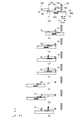
まず、今回のインプリント処理の対象となる対象ショット30がウエハ11上に存在すると想定し、この対象ショット30上に樹脂10が塗布された後(塗布工程後)のインプリント装置1の動作を、図2から図4までの図を用いて各時系列で説明する。図2から図4までの各図は、全て、対象ショット30に樹脂10が塗布された後、対象ショット30がパターン部8a直下の押し付け位置まで移動するまでのガス供給機構4によるガス15の供給動作とウエハステージ5の駆動動作とを示す概略断面図である。なお、これらの図では、モールド8を挟んでX軸方向に配置されている第1供給口16aと第2供給口16bとに対して、対象ショット30は、樹脂10が塗布された後にX軸方向+側から−側の押し付け位置に移動するものとする。このうち、図2は、対象ショット30がウエハ11上の移動方向側(X軸方向−側)に存在する場合の動作を示す図である。ここで、対象ショット30の移動方向(X軸方向)において、対象ショット30の位置からX軸方向+側のウエハ11または補助板19の端部までの距離をD1(第1距離)とし、パターン部8aから第1供給口16aまでの距離をD2(第2距離)とする。このとき、図2に示す動作は、ウエハ11上における対象ショット30の位置が、第1距離が第2距離よりも大きい(D1>D2)との条件を満たす場合の動作ということができる。まず、図2(a)に示すように、液滴吐出部24から樹脂10を塗布された対象ショット30は、ウエハステージ5の駆動により液滴吐出部24に直近の第1供給口16aに向かって移動される。次に、図2(b)に示すように、対象ショット30が第1供給口16a付近に位置したところで、第1ガス制御部17aは、第1供給口16aからガス15の供給を開始させ、対象ショット30は、引き続き押し付け位置まで移動される。そして、図2(c)に示すように、第1供給口16aから供給されたガス15は、ウエハ11の移動に伴ってモールド8とウエハ11との隙間空間に引き込まれ、特にパターン部8a付近のガス濃度が効率的に高められる。なお、隙間空間でのガス濃度は、モールド8とウエハ11との隙間が狭いほうがより高く維持されるため、隙間間隔は、0.1〜1mm程度とすることが望ましい。このように、上記のD1>D2の条件を満たす場合の動作であれば、対象ショット30が押し付け位置まで移動する間、ガス15を供給中の第1供給口16aの直下(供給位置)には、常にウエハ11または補助板19が対向する。したがって、図2に示す動作では、第1供給口16aの直下から押し付け位置の直下までの間でモールド8とウエハ11との隙間空間は維持される。   First, it is assumed that the target shot 30 to be subjected to the imprint process of this time exists on the wafer 11, and the operation of the imprint apparatus 1 after the resin 10 is applied on the target shot 30 (after the coating process) is performed. Each time series will be described with reference to FIGS. 2 to 4. 2 to 4, all of the drawings from FIG. 2 to FIG. 4 show that the gas supply mechanism 4 supplies the gas 15 after the resin 10 is applied to the target shot 30 until the target shot 30 moves to the pressing position immediately below the pattern portion 8a. FIG. 6 is a schematic cross-sectional view showing an operation and a driving operation of the wafer stage 5. In these drawings, the target shot 30 is applied to the X axis after the resin 10 is applied to the first supply port 16a and the second supply port 16b arranged in the X axis direction with the mold 8 interposed therebetween. The direction moves from the + side to the-side pressing position. Among these, FIG. 2 is a diagram illustrating an operation when the target shot 30 exists on the movement direction side (X-axis direction-side) on the wafer 11. Here, in the movement direction (X-axis direction) of the target shot 30, the distance from the position of the target shot 30 to the end of the wafer 11 or the auxiliary plate 19 on the X-axis direction + side is defined as D1 (first distance). The distance from the part 8a to the first supply port 16a is defined as D2 (second distance). At this time, the operation shown in FIG. 2 can be said to be an operation when the position of the target shot 30 on the wafer 11 satisfies the condition that the first distance is larger than the second distance (D1> D2). First, as shown in FIG. 2A, the target shot 30 to which the resin 10 is applied from the droplet discharge unit 24 is directed to the first supply port 16 a closest to the droplet discharge unit 24 by driving the wafer stage 5. Moved. Next, as shown in FIG. 2B, when the target shot 30 is located in the vicinity of the first supply port 16a, the first gas control unit 17a starts supplying the gas 15 from the first supply port 16a, The target shot 30 is continuously moved to the pressing position. As shown in FIG. 2C, the gas 15 supplied from the first supply port 16a is drawn into the gap space between the mold 8 and the wafer 11 as the wafer 11 moves, particularly near the pattern portion 8a. The gas concentration is efficiently increased. Note that the gas concentration in the gap space is maintained higher when the gap between the mold 8 and the wafer 11 is narrower. Therefore, the gap interval is preferably about 0.1 to 1 mm. As described above, when the operation satisfies the condition of D1> D2, the target shot 30 moves to the pressing position, and is directly below the first supply port 16a that is supplying the gas 15 (supply position). The wafer 11 or the auxiliary plate 19 always faces each other. Therefore, in the operation shown in FIG. 2, the gap space between the mold 8 and the wafer 11 is maintained between immediately below the first supply port 16a and immediately below the pressing position.

これに対して、ウエハ11上の対象ショット30の位置が、図2における場合とは反対に、ウエハ11上の移動方向の下流側(X軸方向+側)に存在する場合について考える。図3は、図2および後述の図4に対応する比較の形態として、対象ショット30がウエハ11上の移動方向の下流側に存在する場合の従来の動作を示す図である。この図3に示す動作は、図2の説明にて定義した各距離D1、D2を用いると、ウエハ11上における対象ショット30の位置が、第1距離が第2距離と同一またはそれよりも小さい(D1≦D2)との条件を満たす場合の動作ということができる。この場合も、まず、図3(a)に示すように、液滴吐出部24から樹脂10を塗布された対象ショット30は、ウエハステージ5の駆動により液滴吐出部24に直近の第1供給口16aに向かって移動される。また、図3(b)に示すように、対象ショット30が第1供給口16a付近に位置したところで、第1ガス制御部17aは、第1供給口16aからガス15の供給を開始させ、対象ショット30は、引き続き押し付け位置まで移動される。しかしながら、図3(c)に示すように、対象ショット30が押し付け位置まで移動したとき、ガス15を供給中の第1供給口16aの直下には、ウエハ11または補助板19のいずれも存在しない。したがって、第1供給口16aの直下から押し付け位置までの間では、モールド8とウエハ11との間で隙間空間を形成することができず、ガス15を対象ショット30の移動に伴わせて効率的に引き込むことができない。すなわち、図3に示す動作では、特にパターン部8a付近のガス濃度を効率的に高めることが難しい。また、特に図3(c)に示す状態では、第1供給口16aからのガス15がウエハステージ5の外側に大量に漏れ出すため、例えば、ウエハステージ5の位置を計測するレーザー干渉計22の光路にガス15が侵入し、計測値に影響を与える可能性もある。   On the other hand, consider the case where the position of the target shot 30 on the wafer 11 exists on the downstream side (X-axis direction + side) of the movement direction on the wafer 11, contrary to the case in FIG. 2. FIG. 3 is a diagram showing a conventional operation when the target shot 30 exists on the downstream side in the movement direction on the wafer 11 as a comparison form corresponding to FIG. 2 and FIG. 4 described later. In the operation shown in FIG. 3, when the distances D1 and D2 defined in the description of FIG. 2 are used, the position of the target shot 30 on the wafer 11 is equal to or smaller than the second distance. It can be said that the operation is performed when the condition of (D1 ≦ D2) is satisfied. Also in this case, first, as shown in FIG. 3A, the target shot 30 to which the resin 10 is applied from the droplet discharge unit 24 is first supplied to the droplet discharge unit 24 immediately after the wafer stage 5 is driven. It is moved toward the mouth 16a. As shown in FIG. 3B, when the target shot 30 is located near the first supply port 16a, the first gas control unit 17a starts supplying the gas 15 from the first supply port 16a, The shot 30 is continuously moved to the pressing position. However, as shown in FIG. 3C, when the target shot 30 moves to the pressing position, neither the wafer 11 nor the auxiliary plate 19 exists immediately below the first supply port 16a that is supplying the gas 15. . Therefore, a gap space cannot be formed between the mold 8 and the wafer 11 between the position immediately below the first supply port 16a and the pressing position, and the gas 15 is efficiently accompanied by the movement of the target shot 30. I can't pull in. That is, in the operation shown in FIG. 3, it is difficult to efficiently increase the gas concentration particularly near the pattern portion 8a. In particular, in the state shown in FIG. 3C, a large amount of gas 15 from the first supply port 16a leaks to the outside of the wafer stage 5, so that, for example, the laser interferometer 22 that measures the position of the wafer stage 5 is used. There is also a possibility that the gas 15 enters the optical path and affects the measured value.

ここで、図3(c)に示すようなウエハステージ5の外側へのガス15の流出を避けるために、例えば、補助板19のXY平面での表面積を大きくすることが考えられる。これにより、ウエハ11上のいずれの対象ショット30が押し付け位置に移動しても、第1供給口16aの直下にはウエハ11または補助板19が存在するため、常にモールド8とウエハ11(または補助板19)との間で、隙間空間が形成されることとなる。しかしながら、補助板19の大型化は、ウエハステージ5、ひいてはインプリント装置1全体の大型化につながり、結果的にインプリント装置1のフットプリントの増大やコストアップなどを引き起こす。そこで、本実施形態では、特にウエハ11上における対象ショット30の位置がD1≦D2の条件を満たす場合には、インプリント装置1は、図4に示すような動作を実施する。   Here, in order to avoid the outflow of the gas 15 to the outside of the wafer stage 5 as shown in FIG. 3C, for example, it is conceivable to increase the surface area of the auxiliary plate 19 on the XY plane. As a result, even if any target shot 30 on the wafer 11 moves to the pressing position, the wafer 11 or the auxiliary plate 19 exists immediately below the first supply port 16a. A gap space is formed between the plate 19). However, the increase in the size of the auxiliary plate 19 leads to an increase in the size of the wafer stage 5 and consequently the entire imprint apparatus 1, resulting in an increase in the footprint of the imprint apparatus 1 and an increase in cost. Therefore, in the present embodiment, particularly when the position of the target shot 30 on the wafer 11 satisfies the condition of D1 ≦ D2, the imprint apparatus 1 performs an operation as shown in FIG.

図4は、図3に示す従来の動作と比較した、対象ショット30がウエハ11上の移動方向の下流側に存在する場合の本実施形態の動作を示す図である。まず、図4(a)に示すように、液滴吐出部24から樹脂10を塗布された対象ショット30は、ウエハステージ5の駆動により液滴吐出部24に直近の第1供給口16aに向かって移動される。このとき、本実施形態では、第1ガス制御部17aは、対象ショット30が第1供給口16a付近に位置しても、第1供給口16aからガス15の供給を開始させない。そして、図4(b)に示すように、対象ショット30は、第1供給口16aとはモールド8を挟んで反対側の第2供給口16bを超えるまで(望ましくは第2供給口16bの直下を若干超えるまで)そのまま移動され、その位置で一旦停止される。次に、図4(c)に示すように、対象ショット30は、ウエハステージ5の駆動により移動方向を逆方向に切り替え、停止位置に直近の第2供給口16bに向かって移動される。そして、対象ショット30が第2供給口16b付近に位置したところで、第2ガス制御部17bは、第2供給口16bからガス15の供給を開始させ、対象ショット30は、引き続き押し付け位置まで移動される。そして、図4(d)に示すように、第2供給口16bから供給されたガス15は、ウエハ11の移動に伴ってモールド8とウエハ11との隙間空間に引き込まれ、特にパターン部8a付近のガス濃度が効率的に高められる。さらに、第2供給口16bから供給されたガス15がウエハステージ5の外側へ流出することも回避させることができる。   FIG. 4 is a diagram showing the operation of the present embodiment when the target shot 30 exists on the downstream side in the movement direction on the wafer 11 as compared with the conventional operation shown in FIG. First, as shown in FIG. 4A, the target shot 30 to which the resin 10 is applied from the droplet discharge unit 24 is directed to the first supply port 16a closest to the droplet discharge unit 24 by driving the wafer stage 5. Moved. At this time, in the present embodiment, the first gas control unit 17a does not start the supply of the gas 15 from the first supply port 16a even if the target shot 30 is located near the first supply port 16a. Then, as shown in FIG. 4B, the target shot 30 is over the second supply port 16b opposite to the first supply port 16a across the mold 8 (desirably directly below the second supply port 16b). It is moved as it is (a little over) and is temporarily stopped at that position. Next, as shown in FIG. 4C, the target shot 30 is moved toward the second supply port 16 b closest to the stop position by switching the movement direction to the reverse direction by driving the wafer stage 5. When the target shot 30 is positioned near the second supply port 16b, the second gas control unit 17b starts supplying the gas 15 from the second supply port 16b, and the target shot 30 is continuously moved to the pressing position. The Then, as shown in FIG. 4D, the gas 15 supplied from the second supply port 16b is drawn into the gap space between the mold 8 and the wafer 11 as the wafer 11 moves, particularly near the pattern portion 8a. The gas concentration is efficiently increased. Further, it is possible to prevent the gas 15 supplied from the second supply port 16b from flowing out of the wafer stage 5.

次に、本実施形態における塗布工程後の上記動作を含むガス15の供給開始から終了までのガス供給工程の全体的な流れについて説明する。図5は、塗布工程後からパターン形成工程を挟んで実施されるガス供給工程の流れを示すフローチャートである。まず、塗布工程が完了すると、制御部7は、ウエハ11上における対象ショット30の位置が、上記D1とD2との関係でいずれの条件を満たすか判断する(ステップS100)。ここで、制御部7は、図2に示すようなD1>D2の条件を満たすと判定した場合、次に、ウエハステージ5により第1供給口16aに向かって対象ショット30を移動させる(ステップS101:図2(a)参照)。次に、制御部7は、対象ショット30が第1供給口16a付近に位置したところで、第1ガス制御部17aに対し、第1供給口16aからガス15の供給を開始させる(ステップS102:図2(b)参照)。ここで、制御部7は、引き続きウエハステージ5により押し付け位置まで対象ショット30を移動させる(ステップS103:図2(c)参照)。次に、制御部7は、押型工程、硬化工程、および離型工程を含む一連のパターン形成工程に移行する(ステップS104)。そして、制御部7は、パターン形成工程完了後、第1ガス制御部17aに対し、第1供給口16aからのガス15の供給を終了させ(ステップS105)、次に処理すべき対象ショット30がウエハ11上に存在するかを判断する工程などの次工程へと移行する。   Next, an overall flow of the gas supply process from the start to the end of the supply of the gas 15 including the above operation after the coating process in the present embodiment will be described. FIG. 5 is a flowchart showing the flow of the gas supply process performed after the coating process with the pattern forming process interposed therebetween. First, when the coating process is completed, the control unit 7 determines which of the conditions of the position of the target shot 30 on the wafer 11 satisfies the relationship between D1 and D2 (step S100). If the control unit 7 determines that the condition of D1> D2 as shown in FIG. 2 is satisfied, the target shot 30 is moved toward the first supply port 16a by the wafer stage 5 (step S101). : See FIG. 2 (a)). Next, when the target shot 30 is located near the first supply port 16a, the control unit 7 causes the first gas control unit 17a to start supplying the gas 15 from the first supply port 16a (step S102: FIG. 2 (b)). Here, the control unit 7 continues to move the target shot 30 to the pressing position by the wafer stage 5 (step S103: see FIG. 2C). Next, the control unit 7 proceeds to a series of pattern forming processes including a stamping process, a curing process, and a mold releasing process (Step S104). Then, after completing the pattern formation process, the control unit 7 ends the supply of the gas 15 from the first supply port 16a to the first gas control unit 17a (step S105), and the target shot 30 to be processed next is determined. The process proceeds to the next process such as a process of determining whether or not the wafer 11 exists.

一方、制御部7は、ステップS100にて、図4に示すようなD1≦D2の条件を満たすと判定した場合、次に、ウエハステージ5により、第2供給口16bに向かって対象ショット30を移動させる(ステップS106:図4(a)参照)。そして、制御部7は、対象ショット30の位置が第2供給口16bを超えた時点で一旦停止させる(図4(b)参照)。次に、制御部7は、ウエハステージ5の駆動により移動方向を逆方向に切り替え、停止位置に直近の第2供給口16bに向かって対象ショット30を移動させる(ステップS107)。次に、制御部7は、対象ショット30が第2供給口16b付近に位置したところで、第2ガス制御部17bに対し、第2供給口16bからガス15の供給を開始させる(ステップS108:図4(c)参照)。ここで、制御部7は、引き続きウエハステージ5により押し付け位置まで対象ショット30を移動させる(ステップS109:図4(d)参照)。次に、制御部7は、ステップS104と同様に、押型工程、硬化工程、および離型工程を含む一連のパターン形成工程に移行する(ステップS110)。そして、制御部7は、パターン形成工程完了後、第2ガス制御部17bに対し、第2供給口16bからのガス15の供給を終了させ(ステップS111)、次に処理すべき対象ショット30がウエハ11上に存在するかを判断する工程などの次工程へと移行する。   On the other hand, if it is determined in step S100 that the condition of D1 ≦ D2 as shown in FIG. 4 is satisfied, the control unit 7 next causes the wafer stage 5 to move the target shot 30 toward the second supply port 16b. Move (step S106: see FIG. 4A). And the control part 7 stops once when the position of the object shot 30 exceeds the 2nd supply port 16b (refer FIG.4 (b)). Next, the control unit 7 switches the moving direction to the reverse direction by driving the wafer stage 5, and moves the target shot 30 toward the second supply port 16b closest to the stop position (step S107). Next, when the target shot 30 is located near the second supply port 16b, the control unit 7 causes the second gas control unit 17b to start supplying the gas 15 from the second supply port 16b (step S108: FIG. 4 (c)). Here, the control unit 7 continues to move the target shot 30 to the pressing position by the wafer stage 5 (step S109: see FIG. 4D). Next, the control part 7 transfers to a series of pattern formation processes including a stamping process, a hardening process, and a mold release process, similarly to step S104 (step S110). Then, after the pattern formation process is completed, the control unit 7 ends the supply of the gas 15 from the second supply port 16b to the second gas control unit 17b (step S111), and the target shot 30 to be processed next is determined. The process proceeds to the next process such as a process of determining whether or not the wafer 11 exists.

このように、インプリント装置1では、ウエハ11上に形成される樹脂パターンでの未充填部分の発生を抑えるために、モールド8とウエハ11上の樹脂10との押し付けの際に、ガス供給機構4によりモールド8とウエハ11との隙間空間にガス15を供給する。このとき、対象ショット30がウエハ11上のどの位置に存在していても、上記のとおり隙間空間を維持させることができるので、ガス濃度をより短時間で効率的に高めることができる。例えば、図4に示す動作のように、対象ショット30の移動方向を変更させる(折り返す)動作が含まれていても、その移動時間は、従来の充填時間(上記のとおり1秒から数十秒以上)と比較して十分に短い。したがって、インプリント装置1は、生産性(スループット)を向上させることができる。さらに、インプリント装置1は、隙間空間を維持させるために補助板19を大型化させる必要がないため、ウエハステージ5を小型にしたままでよく、装置全体の大型化を抑制できる。   As described above, in the imprint apparatus 1, in order to suppress the occurrence of an unfilled portion in the resin pattern formed on the wafer 11, a gas supply mechanism is used when pressing the mold 8 and the resin 10 on the wafer 11. 4, the gas 15 is supplied to the gap space between the mold 8 and the wafer 11. At this time, the gap space can be maintained as described above regardless of the position of the target shot 30 on the wafer 11, so that the gas concentration can be efficiently increased in a shorter time. For example, even if the movement direction of the target shot 30 is changed (turned back) as shown in FIG. 4, the movement time is the same as the conventional filling time (from 1 second to several tens of seconds as described above). It is short enough compared with the above. Therefore, the imprint apparatus 1 can improve productivity (throughput). Furthermore, since the imprint apparatus 1 does not need to increase the size of the auxiliary plate 19 in order to maintain the gap space, the wafer stage 5 can be kept small, and the overall size of the apparatus can be suppressed.

以上のように、本実施形態によれば、ウエハを搭載するウエハステージの大型化を抑制しつつ、モールドの凹凸パターンでの未充填部分の発生を抑える際の効率化に有利なインプリント装置を提供することができる。   As described above, according to the present embodiment, an imprint apparatus that is advantageous in improving the efficiency when suppressing the occurrence of an unfilled portion in the uneven pattern of the mold while suppressing an increase in the size of the wafer stage on which the wafer is mounted. Can be provided.

(第2実施形態)
次に、本発明の第2実施形態に係るインプリント装置について説明する。第1実施形態では、インプリント装置1は、1度に1つの対象ショット30に対してインプリント処理を実施し、そのインプリント処理をウエハ11上に存在する複数のショット分繰り返す。これに対して、本実施形態に係るインプリント装置の特徴は、1度に複数の対象ショット30に対してインプリント処理を実施する点にある。すなわち、本実施形態のインプリント装置は、ガス供給機構4による1度のガス供給中に複数の対象ショット30に対するインプリント処理を実施するものである。ここで、第1実施形態では、1度の対象ショット30の数が1つであるため、ウエハ11上における対象ショット30の位置は、上記と同様に各距離D1、D2を用いて言えば、D1>D2と、D1≦D2との2つの条件を満たす場合で考慮することができた。これに対して、本実施形態では、1度の対象ショット30の数が複数であるため、ウエハ11上における対象ショット30の位置は、以下の3つの条件を満たす場合で考慮する必要がある。すなわち、第1の条件は、複数の対象ショット30のうち全てがD1>D2の条件を満たす場合である。また、第2の条件は、複数の対象ショット30のうち全てがD1≦D2の条件を満たす場合である。さらに、本実施形態に特有の条件として、第3の条件は、複数の対象ショット30に、D1>D2の条件を満たすものと、D1≦D2の条件を満たすものとが混在する場合である。そこで、以下、これら3つの条件のそれぞれについて詳説する。
(Second Embodiment)
Next, an imprint apparatus according to the second embodiment of the present invention will be described. In the first embodiment, the imprint apparatus 1 performs imprint processing on one target shot 30 at a time, and repeats the imprint processing for a plurality of shots existing on the wafer 11. In contrast, the imprint apparatus according to the present embodiment is characterized in that imprint processing is performed on a plurality of target shots 30 at a time. That is, the imprint apparatus according to the present embodiment performs imprint processing on a plurality of target shots 30 during one gas supply by the gas supply mechanism 4. Here, since the number of target shots 30 at one time is one in the first embodiment, the position of the target shot 30 on the wafer 11 can be described using the distances D1 and D2 as described above. This can be considered when the two conditions of D1> D2 and D1 ≦ D2 are satisfied. On the other hand, in the present embodiment, since there are a plurality of target shots 30 at one time, the position of the target shot 30 on the wafer 11 needs to be considered when the following three conditions are satisfied. That is, the first condition is a case where all of the plurality of target shots 30 satisfy the condition of D1> D2. The second condition is a case where all of the target shots 30 satisfy the condition of D1 ≦ D2. Furthermore, as a condition specific to the present embodiment, the third condition is a case where a plurality of target shots 30 include a condition that satisfies the condition of D1> D2 and a condition that satisfies the condition of D1 ≦ D2. Therefore, each of these three conditions will be described in detail below.

図6から図8までの各図は、比較のために、図2や図4に示す説明図に対応し、それぞれ隣接した2つの対象ショット30a、30b上に樹脂10が塗布された後(塗布工程後)の本実施形態のインプリント装置1の動作を各時系列で説明する図である。なお、本実施形態のインプリント装置の構成は、第1実施形態に係るインプリント装置1の構成と同一であるため、各構成要素には同一の符号を付し、説明を省略する。また、これらの各図において、ウエハ11上の2つの対象ショット30a、30bは一例であり、1度の対象ショット30の数などは、これに限定するものではない。   6 to 8 correspond to the explanatory views shown in FIG. 2 and FIG. 4 for comparison, and after the resin 10 is applied on the two adjacent target shots 30a and 30b (application) It is a figure explaining operation | movement of the imprint apparatus 1 of this embodiment after a process in each time series. Note that the configuration of the imprint apparatus according to this embodiment is the same as that of the imprint apparatus 1 according to the first embodiment. In each of these drawings, the two target shots 30a and 30b on the wafer 11 are examples, and the number of target shots 30 at one time is not limited to this.

まず、図6は、第1の条件であるウエハ11上における全ての対象ショット30a、30bの位置がD1>D2の条件を満たす場合の動作を示す図である。まず、図6(a)に示すように、液滴吐出部24から連続して樹脂10を塗布された対象ショット30a、30bは、ウエハステージ5の駆動により液滴吐出部24に直近の第1供給口16aに向かって移動される。次に、図6(b)に示すように、対象ショット30a(移動開始時点でパターン部8aに最も近い位置に存在する対象ショット)が第1供給口16a付近に位置したところで、第1ガス制御部17aは、第1供給口16aからガス15の供給を開始させる。そして、図6(c)に示すように、対象ショット30a、30bは、引き続き押し付け位置に向かって移動され、対象ショット30aが押し付け位置に到達した時点で停止する。この場合も、第1供給口16aから供給されたガス15は、ウエハ11の移動に伴ってモールド8とウエハ11との隙間空間に引き込まれ、特にパターン部8a付近のガス濃度が効率的に高められる。次に、図6(d)に示すように、対象ショット30aに対して押型工程および硬化工程が実施され、その後、図6(e)に示すように、離型工程が実施される。そして、図6(f)に示すように、引き続き隣接する対象ショット30bに対しても、ウエハステージ5により押し付け位置に移動された後、押型工程、硬化工程、および離型工程が実施される。今回の樹脂10が塗布された全ての対象ショット30へのパターン形成が完了したら、次回のインプリント処理対象となる複数の対象ショット30を液滴吐出部24の直下に順次移動させる。このように、第1の条件を満たす場合の動作であれば、連続で樹脂10が塗布された全ての対象ショット30のパターン形成が完了するまで、ガス15を供給中の第1供給口16aの直下には、常にウエハ11または補助板19が対向する。したがって、図6に示す動作では、第1供給口16aの直下から押し付け位置の直下までの間でモールド8とウエハ11との隙間空間は維持される。   First, FIG. 6 is a diagram showing an operation in a case where the positions of all target shots 30a and 30b on the wafer 11, which is the first condition, satisfy the condition of D1> D2. First, as shown in FIG. 6A, the target shots 30 a and 30 b to which the resin 10 has been continuously applied from the droplet discharge unit 24 are driven by the wafer stage 5 so that the first shot closest to the droplet discharge unit 24 is obtained. It moves toward the supply port 16a. Next, as shown in FIG. 6 (b), the first gas control is performed when the target shot 30a (the target shot that is closest to the pattern portion 8a at the start of movement) is positioned in the vicinity of the first supply port 16a. The part 17a starts the supply of the gas 15 from the first supply port 16a. Then, as shown in FIG. 6C, the target shots 30a and 30b are continuously moved toward the pressing position, and are stopped when the target shot 30a reaches the pressing position. Also in this case, the gas 15 supplied from the first supply port 16a is drawn into the gap space between the mold 8 and the wafer 11 as the wafer 11 moves, and the gas concentration particularly in the vicinity of the pattern portion 8a is effectively increased. It is done. Next, as shown in FIG. 6D, a stamping process and a curing process are performed on the target shot 30a, and then a mold release process is performed as shown in FIG. 6E. Then, as shown in FIG. 6 (f), the adjacent target shot 30 b is also moved to the pressing position by the wafer stage 5, and then the pressing process, the curing process, and the releasing process are performed. When pattern formation on all target shots 30 to which the resin 10 is applied is completed, a plurality of target shots 30 to be subjected to the next imprint process are sequentially moved directly below the droplet discharge unit 24. As described above, if the operation is performed when the first condition is satisfied, the first supply port 16a that is supplying the gas 15 is supplied until the pattern formation of all target shots 30 to which the resin 10 is continuously applied is completed. The wafer 11 or the auxiliary plate 19 always faces directly below. Therefore, in the operation shown in FIG. 6, the gap space between the mold 8 and the wafer 11 is maintained between immediately below the first supply port 16a and immediately below the pressing position.

次に、図7は、第2の条件であるウエハ11上における全ての対象ショット30a、30bの位置がD1≦D2の条件を満たす場合の動作を示す図である。まず、図7(a)に示すように、液滴吐出部24から連続して樹脂10を塗布された対象ショット30a、30bは、ウエハステージ5の駆動により液滴吐出部24に直近の第1供給口16aに向かって移動される。このとき、第1ガス制御部17aは、対象ショット30a、30bのいずれもが第1供給口16a付近に位置しても、第1供給口16aからガス15の供給を開始させない。そして、図7(b)に示すように、対象ショット30a、30bは、第1供給口16aとはモールド8を挟んで反対側の第2供給口16bを超えるまで(望ましくは第2供給口16bの直下を若干超えるまで)そのまま移動され、その位置で一旦停止される。次に、図7(c)に示すように、対象ショット30a、30bは、ウエハステージ5の駆動により移動方向を逆方向に切り替え、停止位置に直近の第2供給口16bに向かって移動される。そして、対象ショット30b(移動開始時点でパターン部8aから最も遠い位置に存在する対象ショット)が第2供給口16b付近に位置したところで、第2ガス制御部17bは、第2供給口16bからガス15の供給を開始させる。そして、図7(d)に示すように、対象ショット30a、30bは、引き続き押し付け位置に向かって移動され、対象ショット30bが押し付け位置に到達した時点で停止する。この場合も、第2供給口16bから供給されたガス15は、ウエハ11の移動に伴ってモールド8とウエハ11との隙間空間に引き込まれ、特にパターン部8a付近のガス濃度が効率的に高められる。次に、図7(e)に示すように、対象ショット30bに対して押型工程および硬化工程が実施され、その後、図7(f)に示すように、離型工程が実施される。そして、図7(g)に示すように、引き続き隣接する対象ショット30aに対しても、ウエハステージ5により押し付け位置に移動された後、押型工程、硬化工程、および離型工程が実施される。ここでも、今回の樹脂10が塗布された全ての対象ショット30へのパターン形成が完了したら、次回のインプリント処理対象となる複数の対象ショット30を液滴吐出部24の直下に順次移動させる。このように、第2の条件を満たす場合の動作でも、第1の条件と同様に、連続で樹脂10が塗布された全ての対象ショット30のパターン形成が完了するまで、ガス15を供給中の第1供給口16aの直下には、常にウエハ11または補助板19が対向する。したがって、図7に示す動作では、第2供給口16bの直下から押し付け位置の直下までの間でモールド8とウエハ11との隙間空間は維持される。   Next, FIG. 7 is a diagram showing an operation in a case where the positions of all target shots 30a and 30b on the wafer 11, which is the second condition, satisfy the condition of D1 ≦ D2. First, as shown in FIG. 7A, the target shots 30 a and 30 b to which the resin 10 has been continuously applied from the droplet discharge unit 24 are driven by the wafer stage 5 so that the first shot closest to the droplet discharge unit 24 is obtained. It moves toward the supply port 16a. At this time, the first gas control unit 17a does not start the supply of the gas 15 from the first supply port 16a even if both of the target shots 30a and 30b are located in the vicinity of the first supply port 16a. As shown in FIG. 7B, the target shots 30a and 30b exceed the second supply port 16b opposite to the first supply port 16a across the mold 8 (desirably, the second supply port 16b). It is moved as it is (a little more than just below) and is temporarily stopped at that position. Next, as shown in FIG. 7C, the target shots 30a and 30b are moved toward the second supply port 16b closest to the stop position by switching the moving direction to the reverse direction by driving the wafer stage 5. . Then, when the target shot 30b (the target shot that is the farthest from the pattern portion 8a at the start of movement) is located near the second supply port 16b, the second gas control unit 17b supplies gas from the second supply port 16b. 15 supply is started. Then, as shown in FIG. 7D, the target shots 30a and 30b are continuously moved toward the pressing position, and are stopped when the target shot 30b reaches the pressing position. Also in this case, the gas 15 supplied from the second supply port 16b is drawn into the space between the mold 8 and the wafer 11 as the wafer 11 moves, and the gas concentration particularly in the vicinity of the pattern portion 8a is effectively increased. It is done. Next, as shown in FIG. 7 (e), a stamping process and a curing process are performed on the target shot 30b, and then a mold release process is performed as shown in FIG. 7 (f). Then, as shown in FIG. 7G, the adjacent target shot 30a is also moved to the pressing position by the wafer stage 5, and then the pressing process, the curing process, and the releasing process are performed. Here again, when pattern formation has been completed on all target shots 30 to which the resin 10 has been applied this time, a plurality of target shots 30 to be subjected to the next imprint process are sequentially moved directly below the droplet discharge section 24. As described above, even in the operation when the second condition is satisfied, the gas 15 is being supplied until the pattern formation of all the target shots 30 to which the resin 10 is continuously applied is completed as in the first condition. The wafer 11 or the auxiliary plate 19 always faces directly below the first supply port 16a. Therefore, in the operation shown in FIG. 7, the gap space between the mold 8 and the wafer 11 is maintained from immediately below the second supply port 16b to immediately below the pressing position.

さらに、図8は、第3の条件であるウエハ11上における全ての対象ショット30a、30bのうち対象ショット30aの位置がD1(D1a)>D2の条件を満たし、対象ショット30bの位置がD1(D1b)≦D2の条件を満たす場合の動作を示す図である。まず、図8(a)に示すように、液滴吐出部24から連続して樹脂10を塗布された対象ショット30a、30bは、ウエハステージ5の駆動により液滴吐出部24に直近の第1供給口16aに向かって移動される。次に、図8(b)に示すように、対象ショット30aが第1供給口16a付近に位置したところで、第1ガス制御部17aは、第1供給口16aからガス15の供給を開始させる。そして、図8(c)に示すように、対象ショット30a、30bは、引き続き押し付け位置に向かって移動され、このうち対象ショット30aが押し付け位置に到達した時点で停止する。この場合も、第1供給口16aから供給されたガス15は、ウエハ11の移動に伴ってモールド8とウエハ11との隙間空間に引き込まれ、特にパターン部8a付近のガス濃度が効率的に高められる。ここで、図8(d)に示すように、まず対象ショット30aに対して押型工程および硬化工程が実施され、その後、図8(e)に示すように、離型工程が実施される。なお、1度の対象ショット30の数が3つ以上で、そのうち対象ショット30a以外で位置がD1>D2の条件を満たすものが存在する場合、図6に示す例のように、そのままウエハステージ5の駆動により押し付け位置に移動させ、連続してパターンを形成する。次に、対象ショット30aに対するパターン形成が完了したら、図8(f)に示すように、第1ガス制御部17aは、第1供給口16aからのガス15の供給を停止させる。そして、対象ショット30a、30bは、第1供給口16aとはモールド8を挟んで反対側の第2供給口16bを超えるまで(望ましくは第2供給口16bの直下を若干超えるまで)そのまま移動され、その位置で一旦停止される。次に、図8(g)に示すように、対象ショット30a、30bは、ウエハステージ5の駆動により移動方向を逆方向に切り替え、停止位置に直近の第2供給口16bに向かって移動される。そして、対象ショット30bが第2供給口16b付近に位置したところで、第2ガス制御部17bは、第2供給口16bからガス15の供給を開始させる。引き続き、図8(h)に示すように、対象ショット30a、30bは、押し付け位置に向かって移動され、対象ショット30bが押し付け位置に到達した時点で停止する。この場合も、第2供給口16bから供給されたガス15は、ウエハ11の移動に伴ってモールド8とウエハ11との隙間空間に引き込まれ、特にパターン部8a付近のガス濃度が効率的に高められる。そして、引き続き隣接する対象ショット30aに対しても、ウエハステージ5により押し付け位置に移動された後、押型工程、硬化工程、および離型工程が実施される。ここでも、今回の樹脂10が塗布された全ての対象ショット30へのパターン形成が完了したら、次回のインプリント処理対象となる複数の対象ショット30を液滴吐出部24の直下に順次移動させる。このように、第3の条件を満たす場合の動作でも、連続で樹脂10が塗布された全ての対象ショット30のパターン形成が完了するまで、ガス15を供給中の第1供給口16aの直下には、常にウエハ11または補助板19が対向する。したがって、図8に示す動作では、第1供給口16aまたは第2供給口16bのいずれかの直下から押し付け位置の直下までの間でモールド8とウエハ11との隙間空間は維持される。   Furthermore, FIG. 8 shows that the position of the target shot 30a satisfies the condition of D1 (D1a)> D2 among all the target shots 30a and 30b on the wafer 11, which is the third condition, and the position of the target shot 30b is D1 ( It is a figure which shows operation | movement when satisfy | filling the conditions of D1b) <= D2. First, as shown in FIG. 8A, the target shots 30 a and 30 b to which the resin 10 has been continuously applied from the droplet discharge unit 24 are driven by the wafer stage 5 so that the first shot closest to the droplet discharge unit 24 is obtained. It moves toward the supply port 16a. Next, as shown in FIG. 8B, when the target shot 30a is positioned in the vicinity of the first supply port 16a, the first gas control unit 17a starts supplying the gas 15 from the first supply port 16a. Then, as shown in FIG. 8C, the target shots 30a and 30b are continuously moved toward the pressing position, and stop when the target shot 30a reaches the pressing position. Also in this case, the gas 15 supplied from the first supply port 16a is drawn into the gap space between the mold 8 and the wafer 11 as the wafer 11 moves, and the gas concentration particularly in the vicinity of the pattern portion 8a is effectively increased. It is done. Here, as shown in FIG. 8D, first, a pressing process and a curing process are performed on the target shot 30a, and thereafter, a mold release process is performed as shown in FIG. 8E. If the number of target shots 30 at one time is three or more, and there are those other than the target shot 30a that satisfy the condition of D1> D2, the wafer stage 5 is used as it is, as in the example shown in FIG. The pattern is continuously formed by moving to the pressing position by driving. Next, when the pattern formation for the target shot 30a is completed, as shown in FIG. 8F, the first gas control unit 17a stops the supply of the gas 15 from the first supply port 16a. The target shots 30a and 30b are moved as they are until they exceed the second supply port 16b on the opposite side of the mold 8 with respect to the first supply port 16a (desirably slightly above the second supply port 16b). , Temporarily stopped at that position. Next, as shown in FIG. 8G, the target shots 30a and 30b are moved toward the second supply port 16b closest to the stop position by switching the movement direction to the reverse direction by driving the wafer stage 5. . Then, when the target shot 30b is positioned in the vicinity of the second supply port 16b, the second gas control unit 17b starts supplying the gas 15 from the second supply port 16b. Subsequently, as shown in FIG. 8H, the target shots 30a and 30b are moved toward the pressing position, and are stopped when the target shot 30b reaches the pressing position. Also in this case, the gas 15 supplied from the second supply port 16b is drawn into the space between the mold 8 and the wafer 11 as the wafer 11 moves, and the gas concentration particularly in the vicinity of the pattern portion 8a is effectively increased. It is done. Then, the adjacent target shot 30a is also moved to the pressing position by the wafer stage 5, and then the pressing process, the curing process, and the releasing process are performed. Here again, when pattern formation has been completed on all target shots 30 to which the resin 10 has been applied this time, a plurality of target shots 30 to be subjected to the next imprint process are sequentially moved directly below the droplet discharge section 24. As described above, even in the operation in the case where the third condition is satisfied, until the pattern formation of all the target shots 30 to which the resin 10 is continuously applied is completed, the gas 15 is directly below the first supply port 16a that is supplying the gas 15. Always face the wafer 11 or the auxiliary plate 19. Therefore, in the operation shown in FIG. 8, the gap space between the mold 8 and the wafer 11 is maintained between immediately below either the first supply port 16a or the second supply port 16b and immediately below the pressing position.

次に、本実施形態における塗布工程後の上記動作を含むガス15の供給開始から終了までのガス供給工程の全体的な流れについて説明する。図9は、本実施形態における塗布工程後からパターン形成工程を挟んで実施されるガス供給工程の流れを示すフローチャートである。まず、ウエハ11上の複数(2つ)の対象ショット30a、30bに対して塗布工程が完了すると、制御部7は、全ての対象ショット30a、30bの位置が、上記D1とD2との関係でいずれの条件を満たすか判断する(ステップS200)。ここで、制御部7は、全ての対象ショット30a、30bの位置が図6に示すようなD1>D2の条件を満たすと判定した場合には、以下のステップS201に移行する。まず、制御部7は、ウエハステージ5により第1供給口16aに向かって対象ショット30a、30bを移動させる(ステップS201:図6(a)参照)。次に、制御部7は、最初に処理対象となる対象ショット30aが第1供給口16a付近に位置したところで、第1ガス制御部17aに対し、第1供給口16aからガス15の供給を開始させる(ステップS202:図6(b)参照)。ここで、制御部7は、引き続きウエハステージ5により押し付け位置まで対象ショット30aを移動させる(ステップS203:図6(c)参照)。次に、制御部7は、押型工程、硬化工程、および離型工程を含む一連のパターン形成工程に移行する(ステップS204:図6(d)、(e)参照)。さらに、制御部7は、次に処理対象となる対象ショット30bを、引き続きウエハステージ5により押し付け位置に移動させ(ステップS205:図6(f)参照)、押型工程、硬化工程、および離型工程を実施する(ステップS206)。次に、制御部7は、今回の全ての対象ショット30a、30bに対してパターン形成が完了したかどうかを判断する(ステップS207)。ここで、対象ショット30の数が3つ以上である場合、対象ショット30a、30bの他にもパターンを形成していないものが存在するため、その場合には(NO)、制御部7は、ステップS205に戻り、残りの対象ショットに対するパターン形成を実施させる。一方、制御部7は、全ての対象ショット30a、30bに対してパターン形成が完了したと判定した場合には(YES)、第1ガス制御部17aに対し、第1供給口16aからのガス15の供給を終了させる(ステップS208)。そして、制御部7は、次に処理すべき複数の対象ショット(対象ショット群)がウエハ11上に存在するかを判断する工程などの次工程へと移行する。   Next, an overall flow of the gas supply process from the start to the end of the supply of the gas 15 including the above operation after the coating process in the present embodiment will be described. FIG. 9 is a flowchart showing the flow of a gas supply process that is performed after the coating process in the present embodiment with the pattern formation process interposed therebetween. First, when the coating process is completed for a plurality of (two) target shots 30a and 30b on the wafer 11, the control unit 7 determines that the positions of all the target shots 30a and 30b are related to D1 and D2. It is determined which condition is satisfied (step S200). Here, when it is determined that the positions of all the target shots 30a and 30b satisfy the condition of D1> D2 as illustrated in FIG. 6, the control unit 7 proceeds to the following step S201. First, the control unit 7 moves the target shots 30a and 30b toward the first supply port 16a by the wafer stage 5 (step S201: see FIG. 6A). Next, the control unit 7 starts supplying the gas 15 from the first supply port 16a to the first gas control unit 17a when the target shot 30a to be processed first is located near the first supply port 16a. (Step S202: See FIG. 6B). Here, the control unit 7 continues to move the target shot 30a to the pressing position by the wafer stage 5 (step S203: see FIG. 6C). Next, the control unit 7 proceeds to a series of pattern forming processes including a pressing process, a curing process, and a mold releasing process (Step S204: see FIGS. 6D and 6E). Further, the control unit 7 continues to move the target shot 30b to be processed next to the pressing position by the wafer stage 5 (step S205: see FIG. 6 (f)), the pressing process, the curing process, and the release process. (Step S206). Next, the control unit 7 determines whether pattern formation has been completed for all the current target shots 30a and 30b (step S207). Here, when the number of target shots 30 is three or more, there are those that do not form a pattern in addition to the target shots 30a and 30b. In this case (NO), the control unit 7 Returning to step S205, pattern formation is performed on the remaining target shots. On the other hand, if the control unit 7 determines that pattern formation has been completed for all target shots 30a and 30b (YES), the gas 15 from the first supply port 16a is sent to the first gas control unit 17a. Is terminated (step S208). Then, the control unit 7 proceeds to the next process such as a process of determining whether or not a plurality of target shots (target shot group) to be processed next exist on the wafer 11.

次に、制御部7は、ステップS200にて、全ての対象ショット30a、30bの位置が図7に示すようなD1≦D2の条件を満たすと判定した場合には、以下のステップS209に移行する。まず、制御部7は、ウエハステージ5により第2供給口16bに向かって対象ショット30a、30bを移動させる(ステップS209:図7(a)参照)。そして、制御部7は、対象ショット30bの位置が第2供給口16bを超えた時点で一旦停止させる(図7(b)参照)。次に、制御部7は、ウエハステージ5の駆動により移動方向を逆方向に切り替え、停止位置に直近の第2供給口16bに向かって対象ショット30a、30bを移動させる(ステップS210)。次に、制御部7は、最初に処理対象となる対象ショット30bが第2供給口16b付近に位置したところで、第2ガス制御部17bに対し、第2供給口16bからガス15の供給を開始させる(ステップS211:図7(c)参照)。ここで、制御部7は、引き続きウエハステージ5により押し付け位置まで対象ショット30bを移動させる(ステップS212:図7(d)参照)。次に、制御部7は、押型工程、硬化工程、および離型工程を含む一連のパターン形成工程に移行する(ステップS213:図7(e)、(f)参照)。さらに、制御部7は、次の処理対象となる対象ショット30aを、引き続きウエハステージ5により押し付け位置に移動させ(ステップS214:図7(g)参照)、押型工程、硬化工程、および離型工程を実施する(ステップS215)。次に、制御部7は、今回の全ての対象ショット30a、30bに対してパターン形成が完了したかどうかを判断する(ステップS216)。ここで、対象ショット30の数が3つ以上である場合、対象ショット30a、30bの他にもパターンを形成していないものが存在するため、その場合には(NO)、制御部7は、ステップS214に戻り、残りの対象ショットに対するパターン形成を実施させる。一方、制御部7は、全ての対象ショット30a、30bに対してパターン形成が完了したと判定した場合には(YES)、第2ガス制御部17bに対し、第2供給口16bからのガス15の供給を終了させる(ステップS217)。そして、この場合も制御部7は、次に処理すべき複数の対象ショット(対象ショット群)がウエハ11上に存在するかを判断する工程などの次工程へと移行する。   Next, when it is determined in step S200 that the positions of all the target shots 30a and 30b satisfy the condition of D1 ≦ D2 as shown in FIG. 7, the control unit 7 proceeds to the following step S209. . First, the control unit 7 moves the target shots 30a and 30b toward the second supply port 16b by the wafer stage 5 (step S209: see FIG. 7A). And the control part 7 stops once when the position of the object shot 30b exceeds the 2nd supply port 16b (refer FIG.7 (b)). Next, the control unit 7 switches the moving direction to the reverse direction by driving the wafer stage 5, and moves the target shots 30a and 30b toward the second supply port 16b closest to the stop position (step S210). Next, the control unit 7 starts supplying the gas 15 from the second supply port 16b to the second gas control unit 17b when the target shot 30b to be processed first is located in the vicinity of the second supply port 16b. (Step S211: see FIG. 7C). Here, the control unit 7 continues to move the target shot 30b to the pressing position by the wafer stage 5 (step S212: see FIG. 7D). Next, the control unit 7 shifts to a series of pattern forming steps including a stamping step, a curing step, and a release step (Step S213: see FIGS. 7E and 7F). Further, the control unit 7 continues to move the target shot 30a to be processed next to the pressing position by the wafer stage 5 (step S214: see FIG. 7G), and the pressing process, the curing process, and the releasing process. (Step S215). Next, the control unit 7 determines whether or not pattern formation has been completed for all the current target shots 30a and 30b (step S216). Here, when the number of target shots 30 is three or more, there are those that do not form a pattern in addition to the target shots 30a and 30b. In this case (NO), the control unit 7 Returning to step S214, pattern formation is performed on the remaining target shots. On the other hand, when the control unit 7 determines that pattern formation has been completed for all target shots 30a and 30b (YES), the gas 15 from the second supply port 16b is sent to the second gas control unit 17b. Is terminated (step S217). In this case as well, the control unit 7 proceeds to the next process such as a process of determining whether a plurality of target shots (target shot group) to be processed next exist on the wafer 11.

さらに、制御部7は、ステップS200にて、全ての対象ショット30a、30bのうち、図8に示すように、D1>D2の条件を満たすものと、D1≦D2の条件を満たすものとが混在すると判定した場合には、以下のステップS218に移行する。図10は、図9に示すフローチャート内の工程のうち、特にステップS218以下の工程を抽出したフローチャートである。ここでは、図8を参照し、2つの対象ショット30a、30bのうち、対象ショット30aの位置がD1(D1a)>D2の条件を満たし、対象ショット30bの位置がD1(D1b)≦D2の条件を満たすものと想定する。まず、制御部7は、ウエハステージ5により第1供給口16aに向かって対象ショット30a、30bを移動させる(ステップS218:図8(a)参照)。次に、制御部7は、D1>D2の条件を満たす対象ショット30aが第1供給口16a付近に位置したところで、第1ガス制御部17aに対し、第1供給口16aからガス15の供給を開始させる(ステップS219:図8(b)参照)。ここで、制御部7は、引き続きウエハステージ5により押し付け位置まで対象ショット30aを移動させる(ステップS220:図8(c)参照)。次に、制御部7は、押型工程、硬化工程、および離型工程を含む一連のパターン形成工程に移行する(ステップS221:図8(d)、(e)参照)。次に、制御部7は、全ての対象ショット30のうち、対象ショット30a以外でD1>D2の条件を満たす対象ショットに対してパターン形成が完了したかどうかを判断する(ステップS222)。すなわち、図8に示す例で言えば、D1>D2の条件を満たすものは対象ショット30aのみであるが、対象ショット30の数が3つ以上である場合、対象ショット30a以外にもパターンを形成していないものが存在する場合もある。そこで、その場合には(NO)、制御部7は、ステップS220に戻り、残りの対象ショットに対するパターン形成を実施させる。一方、制御部7は、D1>D2の条件を満たす全ての対象ショット30に対してパターン形成が完了したと判定した場合には(YES)、第1ガス制御部17aに対し、第1供給口16aからのガス15の供給を終了させる(ステップS223)。   Further, in step S200, the control unit 7 mixes all the target shots 30a and 30b that satisfy the condition of D1> D2 and those that satisfy the condition of D1 ≦ D2, as shown in FIG. If it is determined, the process proceeds to the following step S218. FIG. 10 is a flowchart in which steps from step S218 are extracted among the steps in the flowchart shown in FIG. Here, referring to FIG. 8, of the two target shots 30a and 30b, the position of the target shot 30a satisfies the condition of D1 (D1a)> D2, and the position of the target shot 30b is a condition of D1 (D1b) ≦ D2. Assuming that First, the control unit 7 moves the target shots 30a and 30b toward the first supply port 16a by the wafer stage 5 (step S218: see FIG. 8A). Next, when the target shot 30a that satisfies the condition of D1> D2 is located near the first supply port 16a, the control unit 7 supplies the gas 15 from the first supply port 16a to the first gas control unit 17a. Start (step S219: see FIG. 8B). Here, the control unit 7 continues to move the target shot 30a to the pressing position by the wafer stage 5 (step S220: refer to FIG. 8C). Next, the control unit 7 proceeds to a series of pattern forming processes including a pressing process, a curing process, and a mold releasing process (Step S221: see FIGS. 8D and 8E). Next, the control unit 7 determines whether or not pattern formation has been completed for target shots that satisfy the condition of D1> D2 other than the target shot 30a among all target shots 30 (step S222). That is, in the example shown in FIG. 8, only the target shot 30a satisfies the condition of D1> D2, but when the number of target shots 30 is three or more, a pattern is formed in addition to the target shot 30a. There may be things that are not. Therefore, in that case (NO), the control unit 7 returns to step S220 to perform pattern formation for the remaining target shots. On the other hand, when the control unit 7 determines that pattern formation has been completed for all target shots 30 that satisfy the condition of D1> D2 (YES), the control unit 7 supplies the first supply port to the first gas control unit 17a. The supply of the gas 15 from 16a is terminated (step S223).

引き続き、制御部7は、ウエハステージ5により第2供給口16bに向かって対象ショット30a、30bを移動させる(ステップS224:図8(f)参照)。そして、制御部7は、対象ショット30bの位置が第2供給口16bを超えた時点で一旦停止させる。次に、制御部7は、ウエハステージ5の駆動により移動方向を逆方向に切り替え、停止位置に直近の第2供給口16bに向かって対象ショット30a、30bを移動させる(ステップS225)。次に、制御部7は、次の処理対象となる対象ショット30bが第2供給口16b付近に位置したところで、第2ガス制御部17bに対し、第2供給口16bからガス15の供給を開始させる(ステップS226:図8(g)参照)。ここで、制御部7は、引き続きウエハステージ5により押し付け位置まで対象ショット30bを移動させる(ステップS227:図8(h)参照)。次に、制御部7は、押型工程、硬化工程、および離型工程を含む一連のパターン形成工程に移行する(ステップS228)。次に、制御部7は、全ての対象ショット30のうち、対象ショット30b以外でD1≦D2の条件を満たす対象ショットに対してパターン形成が完了したかどうかを判断する(ステップS229)。ここでも、図8に示す例で言えば、D1≦D2の条件を満たすものは対象ショット30bのみであるが、対象ショット30の数が3つ以上である場合、対象ショット30b以外にもパターンを形成していないものが存在する場合もある。そこで、その場合には(NO)、制御部7は、ステップS227に戻り、残りの対象ショットに対するパターン形成を実施させる。一方、制御部7は、D1≦D2の条件を満たす全ての対象ショット30に対してパターン形成が完了したと判定した場合には(YES)、第2ガス制御部17bに対し、第2供給口16bからのガス15の供給を終了させる(ステップS230)。そして、この場合も制御部7は、次に処理すべき複数の対象ショット(対象ショット群)がウエハ11上に存在するかを判断する工程などの次工程へと移行する。   Subsequently, the control unit 7 moves the target shots 30a and 30b toward the second supply port 16b by the wafer stage 5 (step S224: see FIG. 8F). Then, the control unit 7 temporarily stops when the position of the target shot 30b exceeds the second supply port 16b. Next, the control unit 7 switches the moving direction to the reverse direction by driving the wafer stage 5, and moves the target shots 30a and 30b toward the second supply port 16b closest to the stop position (step S225). Next, the control unit 7 starts supplying the gas 15 from the second supply port 16b to the second gas control unit 17b when the target shot 30b to be processed next is positioned near the second supply port 16b. (Step S226: see FIG. 8G). Here, the control unit 7 continues to move the target shot 30b to the pressing position by the wafer stage 5 (step S227: see FIG. 8H). Next, the control unit 7 proceeds to a series of pattern forming processes including a stamping process, a curing process, and a mold releasing process (step S228). Next, the control unit 7 determines whether or not pattern formation has been completed for target shots that satisfy the condition of D1 ≦ D2 except for the target shot 30b among all target shots 30 (step S229). Again, in the example shown in FIG. 8, only the target shot 30b satisfies the condition of D1 ≦ D2. However, when the number of target shots 30 is three or more, there are patterns other than the target shot 30b. Some may not be formed. Therefore, in that case (NO), the control unit 7 returns to step S227 to perform pattern formation for the remaining target shots. On the other hand, when the control unit 7 determines that pattern formation has been completed for all target shots 30 that satisfy the condition of D1 ≦ D2 (YES), the control unit 7 supplies the second supply port to the second gas control unit 17b. Supply of the gas 15 from 16b is complete | finished (step S230). In this case as well, the control unit 7 proceeds to the next process such as a process of determining whether a plurality of target shots (target shot group) to be processed next exist on the wafer 11.

このように、本実施形態によれば、ウエハ11上の複数の対象ショット30に対して、1度のガス供給中に連続してパターンを形成することができる。すなわち、塗布位置である液滴吐出部24の直下と押し付け位置であるパターン部8aの直下との間での対象ショット30の移動が大幅に減少するので、インプリント装置1は、第1実施形態と同様の効果を奏すると共に、さらに生産性を向上させることができる。   As described above, according to the present embodiment, a pattern can be continuously formed for a plurality of target shots 30 on the wafer 11 during one gas supply. That is, since the movement of the target shot 30 between the position immediately below the droplet discharge portion 24 that is the application position and the position immediately below the pattern portion 8a that is the pressing position is greatly reduced, the imprint apparatus 1 is the first embodiment. As well as producing the same effect, the productivity can be further improved.

(物品の製造方法)
物品としてのデバイス(半導体集積回路素子、液晶表示素子等)の製造方法は、上述したインプリント装置を用いて基板(ウエハ、ガラスプレート、フィルム状基板)にパターンを形成する工程を含む。さらに、該製造方法は、パターンを形成された基板をエッチングする工程を含み得る。なお、パターンドメディア(記録媒体)や光学素子などの他の物品を製造する場合には、該製造方法は、エッチングの代わりにパターンを形成された基板を加工する他の処理を含み得る。本実施形態の物品の製造方法は、従来の方法に比べて、物品の性能・品質・生産性・生産コストの少なくとも1つにおいて有利である。
(Product manufacturing method)
A method for manufacturing a device (semiconductor integrated circuit element, liquid crystal display element, etc.) as an article includes a step of forming a pattern on a substrate (wafer, glass plate, film-like substrate) using the above-described imprint apparatus. Furthermore, the manufacturing method may include a step of etching the substrate on which the pattern is formed. In the case of manufacturing other articles such as patterned media (recording media) and optical elements, the manufacturing method may include other processes for processing a substrate on which a pattern is formed instead of etching. The method for manufacturing an article according to this embodiment is advantageous in at least one of the performance, quality, productivity, and production cost of the article as compared with the conventional method.

以上、本発明の好ましい実施形態について説明したが、本発明は、これらの実施形態に限定されず、その要旨の範囲内で種々の変形および変更が可能である。   As mentioned above, although preferable embodiment of this invention was described, this invention is not limited to these embodiment, A various deformation | transformation and change are possible within the range of the summary.

1 インプリント装置
4 ガス供給機構
5 ウエハステージ
6 塗布部
7 制御部
8 モールド
10 樹脂
11 ウエハ
15 ガス
16a 第1供給口
16b 第2供給口
19 補助板
30 対象ショット
DESCRIPTION OF SYMBOLS 1 Imprint apparatus 4 Gas supply mechanism 5 Wafer stage 6 Application | coating part 7 Control part 8 Mold 10 Resin 11 Wafer 15 Gas 16a 1st supply port 16b 2nd supply port 19 Auxiliary plate 30 Target shot

Claims (8)

基板上の未硬化樹脂を型により成形して硬化させて、前記基板上に硬化した樹脂のパターンを形成するインプリント装置であって、
前記基板上のショットに前記未硬化樹脂を塗布する塗布部と、
前記基板を保持して可動で、記基板を保持するための保持面の周囲に配置され補助板を含む基板保持部と、
前記型と前記ショットに塗布された前記未硬化樹脂との押し付けに際し、前記塗布部による塗布位置から前記押し付けが実施される押し付け位置までの前記基板保持部の駆動による前記ショットの移動に伴って、前記型と前記基板との間の隙間空間に気体を供給する複数の供給口を含む気体供給部と、
前記未硬化樹脂が塗布された前記ショットが前記押し付け位置に向かって移動している間において、前記基板または前記補助板のいずれかが、前記複数の供給口のうちの前記気体供給ている前記供給口に対向するように、前記気体供給る前記供給口を選択し、かつ前記ショットの移動方向を制御する制御部と、
を備えることを特徴とするインプリント装置。
An imprint apparatus for forming a cured resin pattern on the substrate by molding and curing an uncured resin on the substrate with a mold,
An application part for applying the uncured resin to the shot on the substrate;
Movable while holding the substrate, and the substrate holding portion including a disposed around the holding surface for holding a pre-Symbol substrate supporting plate,
When pressing the mold and the uncured resin applied to the shot, along with the movement of the shot by driving the substrate holding unit from the application position by the application unit to the pressing position where the pressing is performed, A gas supply unit including a plurality of supply ports for supplying gas to a gap space between the mold and the substrate;
In while the shot the uncured resin is applied is moving toward the pressing position, either the substrate or the auxiliary plate, and supplying the gas of the plurality of supply ports as opposed to the supply port, and a control unit which selects said supply port you supply the gas, and controls the moving direction of the shot,
An imprint apparatus comprising:
前記制御部は、前記基板上での前記押し付けの対象となる前記ショットの位置に関する条件に基づいて、前記気体供給る前記供給口と、前記ショットの移動方向とを切り替えることを特徴とする請求項1に記載のインプリント装置。 Wherein, based on the conditions regarding the position of the shot to be the pressing of the object on the substrate, and switches and the supply port that to supply the gas, and a moving direction of the shot The imprint apparatus according to claim 1. 前記複数の供給口は、前記ショットの移動方向に沿って、前記塗布位置と前記押し付け位置との間に配置される第1供給口と、前記型を挟んで前記第1供給口の反対側に配置される第2供給口とを含み、
前記条件は、前記ショットの移動方向にて、前記ショットから、前記塗布位置から前記押し付け位置に向かう方向とは反対側にある前記基板または前記補助板のいずれかの端部までの第1距離と、前記押し付け位置から前記第1供給口までの第2距離との関係であることを特徴とする請求項2に記載のインプリント装置。
The plurality of supply ports are arranged on the opposite side of the first supply port across the mold, with a first supply port disposed between the application position and the pressing position along the moving direction of the shot A second supply port arranged,
The condition is that, in the moving direction of the shot, a first distance from the shot to an end portion of the substrate or the auxiliary plate that is opposite to the direction from the application position to the pressing position; The imprint apparatus according to claim 2, wherein the imprint apparatus has a relationship with a second distance from the pressing position to the first supply port.
前記制御部は、前記第1距離が前記第2距離よりも大きい場合には、前記未硬化樹脂が塗布された前記ショットが前記押し付け位置に移動しているときに、前記第1供給口により前記気体を供給させることを特徴とする請求項3に記載のインプリント装置。   When the first distance is greater than the second distance, the control unit causes the first supply port to move the shot applied with the uncured resin to the pressing position. The imprint apparatus according to claim 3, wherein gas is supplied. 前記制御部は、前記第1距離が前記第2距離と同一またはそれよりも小さい場合には、前記未硬化樹脂が塗布された前記ショットを前記第2供給口による供給位置を超えるまで移動させ、その後、前記ショットの移動方向を逆方向とし、前記ショットが前記押し付け位置に移動しているときに、前記第2供給口より前記気体を供給させることを特徴とする請求項3に記載のインプリント装置。   When the first distance is equal to or smaller than the second distance, the control unit moves the shot coated with the uncured resin until it exceeds a supply position by the second supply port, 4. The imprint according to claim 3, wherein the gas is supplied from the second supply port when the shot is moved in the reverse direction and the shot is moved to the pressing position. apparatus. 前記制御部は、前記塗布部により前記基板上の複数の前記ショットに対して前記未硬化樹脂を塗布させ、前記隙間空間に前記気体が供給されている間に連続して前記複数のショットに対する前記押し付けを実施させることを特徴とする請求項1ないし5のいずれか1項に記載のインプリント装置。   The control unit applies the uncured resin to the plurality of shots on the substrate by the application unit, and continuously applies the plurality of shots to the plurality of shots while the gas is supplied to the gap space. 6. The imprint apparatus according to claim 1, wherein pressing is performed. 基板上の未硬化樹脂を型により成形して硬化させて、前記基板上に硬化した樹脂のパターンを形成するインプリント方法であって、
前記基板上のショットに前記未硬化樹脂を塗布する工程と、
前記未硬化樹脂が塗布された位置から前記型と前記ショットに塗布された前記未硬化樹脂との押し付けが実施される押し付け位置までの前記ショットの移動に伴って、前記型と前記基板との間の隙間空間に気体を供給する工程と、
前記未硬化樹脂が塗布されたショットが前記押し付け位置に向かって移動している間において、前記基板、または記基板の周囲に配置される補助板のいずれかが、数の供給口のうち前記気体供給ている供給口に対向するように、前記気体供給る前記供給口を選択し、かつ前記ショットの移動方向を制御する工程と、
を含むことを特徴とするインプリント方法。
An imprint method in which an uncured resin on a substrate is molded and cured by a mold to form a cured resin pattern on the substrate,
Applying the uncured resin to the shot on the substrate;
Along with the movement of the shot from the position where the uncured resin is applied to the pressing position where the uncured resin applied to the shot and the mold is pressed, the space between the mold and the substrate Supplying gas to the gap space of
Between the shots the uncured resin is applied is moving toward the pressing position, one of the auxiliary plate disposed around the substrate or previous SL substrate, is, among the multiple supply ports so as to face the supply port that supplies the gas, the steps of the gas select the supply port you supply, and controls the moving direction of the shot,
The imprint method characterized by including.
請求項1ないし6のいずれか1項に記載のインプリント装置、または請求項7に記載のインプリント方法を用いて基板上に樹脂のパターンを形成する工程と、
前記工程で前記パターンを形成された基板を加工する工程と、
を含むことを特徴とする物品の製造方法。
Forming a resin pattern on a substrate using the imprint apparatus according to any one of claims 1 to 6 or the imprint method according to claim 7;
Processing the substrate on which the pattern is formed in the step;
A method for producing an article comprising:
JP2012039813A 2012-02-27 2012-02-27 Imprint apparatus, imprint method, and article manufacturing method using the same Expired - Fee Related JP5868215B2 (en)

Priority Applications (5)

Application Number Priority Date Filing Date Title
JP2012039813A JP5868215B2 (en) 2012-02-27 2012-02-27 Imprint apparatus, imprint method, and article manufacturing method using the same
KR1020147023122A KR101698253B1 (en) 2012-02-27 2013-02-26 Imprint apparatus and imprint method, and article manufacturing method
CN201380010484.1A CN104137224B (en) 2012-02-27 2013-02-26 Imprinting apparatus and method for stamping and article manufacturing method
US14/376,334 US10105892B2 (en) 2012-02-27 2013-02-26 Imprint apparatus and imprint method, and article manufacturing method
PCT/JP2013/001092 WO2013128888A1 (en) 2012-02-27 2013-02-26 Imprint apparatus and imprint method, and article manufacturing method

Applications Claiming Priority (1)

Application Number Priority Date Filing Date Title
JP2012039813A JP5868215B2 (en) 2012-02-27 2012-02-27 Imprint apparatus, imprint method, and article manufacturing method using the same

Publications (3)

Publication Number Publication Date
JP2013175631A JP2013175631A (en) 2013-09-05
JP2013175631A5 JP2013175631A5 (en) 2015-04-09
JP5868215B2 true JP5868215B2 (en) 2016-02-24

Family

ID=49082101

Family Applications (1)

Application Number Title Priority Date Filing Date
JP2012039813A Expired - Fee Related JP5868215B2 (en) 2012-02-27 2012-02-27 Imprint apparatus, imprint method, and article manufacturing method using the same

Country Status (5)

Country Link
US (1) US10105892B2 (en)
JP (1) JP5868215B2 (en)
KR (1) KR101698253B1 (en)
CN (1) CN104137224B (en)
WO (1) WO2013128888A1 (en)

Families Citing this family (16)

* Cited by examiner, † Cited by third party
Publication number Priority date Publication date Assignee Title
JP6294679B2 (en) * 2014-01-21 2018-03-14 キヤノン株式会社 Imprint apparatus and article manufacturing method
JP6525567B2 (en) * 2014-12-02 2019-06-05 キヤノン株式会社 Imprint apparatus and method of manufacturing article
US10571801B2 (en) * 2014-12-09 2020-02-25 Canon Kabushiki Kaisha Coating apparatus, imprint apparatus, and method of manufacturing article
JPWO2017002506A1 (en) * 2015-06-29 2018-04-26 日産化学工業株式会社 Imprint material
US10204780B2 (en) * 2015-09-08 2019-02-12 Canon Kabushiki Kaisha Imprint apparatus, and article manufacturing method
JP6702753B2 (en) * 2016-02-17 2020-06-03 キヤノン株式会社 Lithographic apparatus and method for manufacturing article
JP6313795B2 (en) * 2016-03-03 2018-04-18 キヤノン株式会社 Shutter unit, lithographic apparatus, imprint apparatus, and article manufacturing method
JP6700949B2 (en) * 2016-04-28 2020-05-27 キヤノン株式会社 Imprint method and article manufacturing method
JP6735656B2 (en) * 2016-11-18 2020-08-05 キヤノン株式会社 Imprint apparatus, imprint method, and article manufacturing method
KR102369538B1 (en) * 2017-09-28 2022-03-03 캐논 가부시끼가이샤 Shaping apparatus and article manufacturing method
JP7064310B2 (en) * 2017-10-24 2022-05-10 キヤノン株式会社 Imprinting equipment and article manufacturing method
CN109828437A (en) * 2017-11-23 2019-05-31 志圣工业股份有限公司 Anti-stick hardened structure
JP7210155B2 (en) * 2018-04-16 2023-01-23 キヤノン株式会社 Apparatus, methods, and methods of making articles
JP7134790B2 (en) * 2018-08-28 2022-09-12 キオクシア株式会社 IMPRINT APPARATUS, IMPRINT METHOD, AND SEMICONDUCTOR DEVICE MANUFACTURING METHOD
JP7149872B2 (en) * 2019-02-14 2022-10-07 キヤノン株式会社 IMPRINT METHOD, IMPRINT APPARATUS, AND ARTICLE MANUFACTURING METHOD
JP2022092734A (en) * 2020-12-11 2022-06-23 キヤノン株式会社 Imprint device, imprint method, method for manufacturing article, and computer program

Family Cites Families (11)

* Cited by examiner, † Cited by third party
Publication number Priority date Publication date Assignee Title
US8211214B2 (en) 2003-10-02 2012-07-03 Molecular Imprints, Inc. Single phase fluid imprint lithography method
US8144309B2 (en) * 2007-09-05 2012-03-27 Asml Netherlands B.V. Imprint lithography
JPWO2009153925A1 (en) 2008-06-17 2011-11-24 株式会社ニコン Nanoimprint method and apparatus
JP4892025B2 (en) * 2008-09-26 2012-03-07 株式会社東芝 Imprint method
US20110140304A1 (en) * 2009-12-10 2011-06-16 Molecular Imprints, Inc. Imprint lithography template
JP5451450B2 (en) 2010-02-24 2014-03-26 キヤノン株式会社 Imprint apparatus, template thereof, and article manufacturing method
JP5618588B2 (en) 2010-03-24 2014-11-05 キヤノン株式会社 Imprint method
JP2011230430A (en) * 2010-04-28 2011-11-17 Toshiba Corp Template repair method, pattern forming method, and template repair apparatus
JP5597031B2 (en) 2010-05-31 2014-10-01 キヤノン株式会社 Lithographic apparatus and article manufacturing method
JP5744422B2 (en) * 2010-06-17 2015-07-08 キヤノン株式会社 Imprint method, imprint apparatus, sample shot extraction method, and article manufacturing method using the same
JP2012039057A (en) * 2010-07-13 2012-02-23 Canon Inc Imprint apparatus and method of manufacturing article

Also Published As

Publication number Publication date
KR20140116209A (en) 2014-10-01
WO2013128888A1 (en) 2013-09-06
CN104137224B (en) 2016-08-17
US20150042012A1 (en) 2015-02-12
JP2013175631A (en) 2013-09-05
US10105892B2 (en) 2018-10-23
CN104137224A (en) 2014-11-05
KR101698253B1 (en) 2017-01-19

Similar Documents

Publication Publication Date Title
JP5868215B2 (en) Imprint apparatus, imprint method, and article manufacturing method using the same
US11249394B2 (en) Imprint methods for forming a pattern of an imprint material on a substrate-side pattern region of a substrate by using a mold, and related device manufacturing methods
JP6230041B2 (en) Imprint apparatus and article manufacturing method using the same
JP6021606B2 (en) Imprint apparatus, article manufacturing method using the same, and imprint method
JP6061524B2 (en) Imprint apparatus and article manufacturing method
KR101656161B1 (en) Imprint apparatus and article manufacturing method using same
US10168615B2 (en) Imprint apparatus, imprint method, and article manufacturing method
US8734702B2 (en) Original and article manufacturing method using same
JP2013125817A (en) Imprint device, imprint method, and article manufacturing method using the device or the method
JP2015018983A (en) Imprint apparatus and imprint method, and method for manufacturing article by using the same
JP5995567B2 (en) Imprint apparatus and article manufacturing method using the same
JP5865528B2 (en) Imprint apparatus, imprint method, and device manufacturing method
JP2017135369A (en) Copying method of mold, imprint device, and method of manufacturing article
JP2013225616A (en) Imprint method and method of manufacturing article using the same
JP2022092734A (en) Imprint device, imprint method, method for manufacturing article, and computer program
JP2019016648A (en) Imprinting method, imprint apparatus, and article manufacturing method

Legal Events

Date Code Title Description
A521 Request for written amendment filed

Free format text: JAPANESE INTERMEDIATE CODE: A523

Effective date: 20150224

A621 Written request for application examination

Free format text: JAPANESE INTERMEDIATE CODE: A621

Effective date: 20150224

TRDD Decision of grant or rejection written
A01 Written decision to grant a patent or to grant a registration (utility model)

Free format text: JAPANESE INTERMEDIATE CODE: A01

Effective date: 20151208

A61 First payment of annual fees (during grant procedure)

Free format text: JAPANESE INTERMEDIATE CODE: A61

Effective date: 20160105

R151 Written notification of patent or utility model registration

Ref document number: 5868215

Country of ref document: JP

Free format text: JAPANESE INTERMEDIATE CODE: R151

LAPS Cancellation because of no payment of annual fees