JP5840818B2 - Method and apparatus for cooling surfaces in casting equipment, rolling equipment or other strip process lines - Google Patents
Method and apparatus for cooling surfaces in casting equipment, rolling equipment or other strip process lines Download PDFInfo
- Publication number
- JP5840818B2 JP5840818B2 JP2015519179A JP2015519179A JP5840818B2 JP 5840818 B2 JP5840818 B2 JP 5840818B2 JP 2015519179 A JP2015519179 A JP 2015519179A JP 2015519179 A JP2015519179 A JP 2015519179A JP 5840818 B2 JP5840818 B2 JP 5840818B2
- Authority
- JP
- Japan
- Prior art keywords
- nozzle
- cooled
- outlet
- cooling
- roll
- Prior art date
- Legal status (The legal status is an assumption and is not a legal conclusion. Google has not performed a legal analysis and makes no representation as to the accuracy of the status listed.)
- Expired - Fee Related
Links
Images


Classifications
-
- B—PERFORMING OPERATIONS; TRANSPORTING
- B21—MECHANICAL METAL-WORKING WITHOUT ESSENTIALLY REMOVING MATERIAL; PUNCHING METAL
- B21B—ROLLING OF METAL
- B21B45/00—Devices for surface or other treatment of work, specially combined with or arranged in, or specially adapted for use in connection with, metal-rolling mills
- B21B45/02—Devices for surface or other treatment of work, specially combined with or arranged in, or specially adapted for use in connection with, metal-rolling mills for lubricating, cooling, or cleaning
- B21B45/0203—Cooling
- B21B45/0209—Cooling devices, e.g. using gaseous coolants
- B21B45/0215—Cooling devices, e.g. using gaseous coolants using liquid coolants, e.g. for sections, for tubes
- B21B45/0233—Spray nozzles, Nozzle headers; Spray systems
-
- B—PERFORMING OPERATIONS; TRANSPORTING
- B21—MECHANICAL METAL-WORKING WITHOUT ESSENTIALLY REMOVING MATERIAL; PUNCHING METAL
- B21B—ROLLING OF METAL
- B21B27/00—Rolls, roll alloys or roll fabrication; Lubricating, cooling or heating rolls while in use
- B21B27/06—Lubricating, cooling or heating rolls
- B21B27/10—Lubricating, cooling or heating rolls externally
-
- B—PERFORMING OPERATIONS; TRANSPORTING
- B21—MECHANICAL METAL-WORKING WITHOUT ESSENTIALLY REMOVING MATERIAL; PUNCHING METAL
- B21B—ROLLING OF METAL
- B21B45/00—Devices for surface or other treatment of work, specially combined with or arranged in, or specially adapted for use in connection with, metal-rolling mills
- B21B45/02—Devices for surface or other treatment of work, specially combined with or arranged in, or specially adapted for use in connection with, metal-rolling mills for lubricating, cooling, or cleaning
- B21B45/0203—Cooling
- B21B45/0209—Cooling devices, e.g. using gaseous coolants
- B21B45/0215—Cooling devices, e.g. using gaseous coolants using liquid coolants, e.g. for sections, for tubes
- B21B45/0218—Cooling devices, e.g. using gaseous coolants using liquid coolants, e.g. for sections, for tubes for strips, sheets, or plates
-
- B—PERFORMING OPERATIONS; TRANSPORTING
- B21—MECHANICAL METAL-WORKING WITHOUT ESSENTIALLY REMOVING MATERIAL; PUNCHING METAL
- B21B—ROLLING OF METAL
- B21B27/00—Rolls, roll alloys or roll fabrication; Lubricating, cooling or heating rolls while in use
- B21B27/06—Lubricating, cooling or heating rolls
- B21B27/10—Lubricating, cooling or heating rolls externally
- B21B2027/103—Lubricating, cooling or heating rolls externally cooling externally
Description
本発明は、鋳造設備、圧延設備又はそれ以外のストリッププロセスラインにおいて表面を冷却するための方法及び装置を目指している。この場合、好ましくは冷媒が、鋳造材、圧延材、特にストリップもしくは板材、又はロールの表面に塗布される。 The present invention is directed to a method and apparatus for cooling a surface in a casting facility, rolling facility or other strip process line. In this case, the coolant is preferably applied to the surface of the cast material, rolled material, in particular strip or plate material, or roll.
従来技術から、ストリップ又はロールを冷却するための多数の方法が知られている。 A number of methods for cooling a strip or roll are known from the prior art.
独国特許出願公開第41 16 019号明細書は、フルジェットノズルとして形成された液体ノズルを両側に配置したストリップを冷却するための装置に関する。これらノズルにより、平行ジェットが構成され、個々の平行ジェットの衝突点の周囲に閉鎖流の領域が形成される。この装置の場合、ジェットが、自由に衝突し、どのようなガイド又はストリップ表面への制限装置も有しない。このような装置において欠点であるのは、例えば、比較的高い水の消費量と、努力が行なわれるにもかかわらず回避が困難でしかない閉鎖流と冷却すべき表面の間の蒸気層の形成とにある。 German Offenlegungsschrift 41 16 019 relates to a device for cooling a strip with liquid nozzles arranged as full jet nozzles arranged on both sides. These nozzles constitute a parallel jet and form a closed flow region around the impact point of the individual parallel jets. In this device, the jets collide freely and do not have any guide or strip surface restriction. Disadvantages in such devices are, for example, relatively high water consumption and the formation of a vapor layer between the closed flow and the surface to be cooled, which is difficult to avoid despite efforts. It is in.
独国特許出願公開第27 51 013号明細書は、水滴を含有するスプレージェットが発生され、冷却すべき金属プレートに整向される冷却ユニットを開示する。このために必要なノズルは、ベンチュリーチューブとしてとして形成され、このベンチュリーチューブを経て、空気と水の適切な混合物が移送される。これから生じる多相の冷却剤流は、冷却作用を著しく損なう蒸気層を生じさせる。 German Offenlegungsschrift 27 51 013 discloses a cooling unit in which a spray jet containing water droplets is generated and directed to a metal plate to be cooled. The nozzle required for this is formed as a venturi tube, through which a suitable mixture of air and water is transferred. The resulting multiphase coolant flow creates a vapor layer that significantly impairs the cooling action.
特開2005−118838号公報は、スプレーノズルにより冷却をするための装置を開示する。スプレーノズルの仕様により、液体と気体状の成分から成るジェットが生じる。これにより、冷却すべき金属上に効果的な冷却を阻害する蒸気層も形成される。 Japanese Patent Laying-Open No. 2005-118838 discloses an apparatus for cooling by a spray nozzle. Depending on the specifications of the spray nozzle, a jet consisting of liquid and gaseous components is produced. This also forms a vapor layer that hinders effective cooling on the metal to be cooled.
特開昭57−156830号公報は、ノズルと、このノズルから冷却すべきストリップの表面に対して平行に延在するプレート状のガイドとを備える、圧延されたストリップを冷却するための装置を開示する。ノズルから流出する冷却水は、プレート状のガイドと冷却すべき表面の間に、ストリップを冷却するための水膜を構成する。ノズルとプレート状のガイドは、スプレーバーを介して不動に高さ調整可能なクロスビームに取付けられているので、ノズルと冷却すべきストリップ表面の間の間隔は、クロスビームの昇降を介して調整可能である。JP 57-156830 discloses an apparatus for cooling a rolled strip comprising a nozzle and a plate-shaped guide extending parallel to the surface of the strip to be cooled from this nozzle. To do. The cooling water flowing out from the nozzle forms a water film for cooling the strip between the plate-shaped guide and the surface to be cooled. The nozzle and plate-shaped guide are fixedly attached to a cross beam whose height can be adjusted via a spray bar, so that the distance between the nozzle and the surface of the strip to be cooled is adjusted by raising and lowering the cross beam. Is possible.
本発明の課題は、改善された、鋳造材、圧延材又はロールを冷却するための方法を提供することにある。好ましくは、課題は、前記欠点の少なくとも1つを克服することにある。特に好ましくは、必要な冷却材料を低減するもしくは冷却の効率、効果及び/又は柔軟性を改善するべきである。 The object of the present invention is to provide an improved method for cooling a cast, rolled or roll. Preferably, the task is to overcome at least one of the aforementioned drawbacks. Particularly preferably, the required cooling material should be reduced or the efficiency, effectiveness and / or flexibility of the cooling should be improved.
この技術的課題は、独立請求項1の特徴によって解決される。請求した、鋳造材、圧延材(特にストリップ又は板材)又はロールの表面を冷却するための方法によれば、第1の内法もしくは内側の横断面を有する入口と冷却すべき表面に向かい合う、特に第1の横断面よりも大きい第2の内法もしくは内側の横断面を有する出口とを有するノズルが準備される。更に、入口を介してノズルに供給され、出口を経てノズルから出る冷却流体の特に単相の容積流が供給される。少なくともノズル出口又はノズルは、冷却すべき表面に対して可変の(もしくは自由に調整可能な)間隔をもって支承されている。加えて、ノズルの入口に供給される冷却流体の容積流は、ノズルもしくはノズル出口がベルヌーイの原理(もしくは流体力学的パラドックス)に従って冷却すべき表面に(自主的に)吸い付くように調整される。 This technical problem is solved by the features of independent claim 1. According to the claimed method for cooling the surface of a cast, rolled material (especially strip or plate) or roll, the inlet having the first inner method or inner cross-section and the surface to be cooled, in particular, A nozzle is provided having a second inner method larger than the first cross section or an outlet having an inner cross section. Furthermore, it is supplied to the nozzle through the inlet, volume flow particularly in a single phase of the cooling fluid exiting the nozzle is supplied through the outlet. At least the nozzle outlet or nozzle is mounted with a variable (or freely adjustable) spacing relative to the surface to be cooled. In addition, the volumetric flow of cooling fluid supplied to the nozzle inlet is adjusted so that the nozzle or nozzle outlet (voluntarily) sticks to the surface to be cooled according to Bernoulli's principle (or hydrodynamic paradox) .
ノズルが、冷却すべき表面に対して可変のもしくは自由に調整可能な間隔をもって支承され、ノズルを経て流れる冷却流体の容積流が、ベルヌーイの原理に従って自発的に冷却すべき表面に吸い付くように調整されることにより、表面の効果的な冷却が可能にされる。前記の原理に従って、ノズル出口からの冷却流体(例えば水、空気、又は、水とオイルから成るエマルジョン)の流出時に、ノズルの周囲に対して相対的に低い圧力(負圧)が生じ、この圧力は、ノズルが冷却すべき表面に吸い付く又は換言すれば出口と表面の間の間隔が自主的に低下することを生じさせる。これは、例えば、出口から流出する流体の流速を高め、これにより、ベルヌーイの原理に従ってノズルから流出する液体の圧力を低下させることによって、生じさせることができる。冷却すべき表面とノズル出口の間の流れの領域内のこの圧力低下により、ノズルの周囲内の圧力に対する圧力差に基づいてノズルが冷却すべき表面に吸い付く状態が得られる。但し、ノズルは、容積流が(永続的に)入口を経てノズルに供給もしくは補充されるので、冷却すべき表面と衝突することはない。従って、特に一定の容積流の場合には、ノズル出口と冷却すべき表面の間に実質的に一定の間隔が保証される。この間隔は、自己調整式であるか、換言すれば、間隔は、自動的に調整される。 The nozzle is mounted with a variable or freely adjustable spacing relative to the surface to be cooled, so that the volumetric flow of cooling fluid flowing through the nozzle is spontaneously attracted to the surface to be cooled according to Bernoulli's principle Adjusting allows for effective cooling of the surface. In accordance with the principle described above, a relatively low pressure (negative pressure) is generated around the nozzle when a cooling fluid (eg water, air or an emulsion of water and oil) flows out of the nozzle outlet, and this pressure Causes the nozzle to stick to the surface to be cooled or, in other words, to reduce the distance between the outlet and the surface voluntarily. This can occur, for example, by increasing the flow rate of the fluid flowing out of the outlet, thereby reducing the pressure of the liquid flowing out of the nozzle according to Bernoulli's principle. This pressure drop in the region of flow between the surface to be cooled and the nozzle outlet results in the nozzle sticking to the surface to be cooled based on the pressure difference relative to the pressure in the circumference of the nozzle. However, the nozzle does not collide with the surface to be cooled because the volume flow is (permanently) supplied or replenished to the nozzle via the inlet. A substantially constant spacing is thus ensured between the nozzle outlet and the surface to be cooled, especially in the case of a constant volume flow. This interval is self-adjusting, in other words, the interval is automatically adjusted.
表面に対して間隔を置いたノズルの可変もしくは可動の支承は、このましくは0.1mm〜5mmの、特に0.5mm〜2mmの範囲とすることができる。 The variable or movable bearing of the nozzle spaced from the surface can preferably be in the range from 0.1 mm to 5 mm, in particular from 0.5 mm to 2 mm.
本発明の更なる利点は、冷却すべき表面とノズルの間の高い熱伝達係数と、公知のシステムに対する効率向上を含んでいる。加えて、ストリップ走行方向のストリップの冷却時の冷却装置の長さは、高められた効率によって低減させることができる。特に、冷却剤は、必要な箇所に直接的に塗布することができるので、一方では、冷却すべき表面の個々の領域が適切に冷却され、他方では冷却をするための冷却剤の損失が回避される。迷走する冷媒の表面に、ノズルによって本来の冷却ゾーンから遮蔽される。従って、ノズルの冷却能力は、大幅に、迷走する冷媒に依存しない。複数のノズルが、ロール又はストリップの幅にわたって分配されている場合、ロール又はストリップの部分領域は、これら領域内のノズルを停止することによって、それほど強く冷却されないか、全く冷却されないままにすることができる。 Further advantages of the present invention include a high heat transfer coefficient between the surface to be cooled and the nozzle and increased efficiency over known systems. In addition, the length of the cooling device when cooling the strip in the strip running direction can be reduced by the increased efficiency. In particular, the coolant can be applied directly where it is needed, so that on the one hand the individual areas of the surface to be cooled are adequately cooled and on the other hand the loss of coolant for cooling is avoided. Is done. The surface of the stray refrigerant is shielded from the original cooling zone by the nozzle. Therefore, the cooling capacity of the nozzle is largely independent of the stray refrigerant. If multiple nozzles are distributed across the width of the roll or strip, the partial areas of the roll or strip may remain less cooled or not cooled at all by stopping the nozzles in these areas. it can.
方法の好ましい実施形態によれば、出口の間隔が、実質的に冷却すべき表面に対して垂直に位置する方向に(だけ)可変である。これは、間隔が固定の寸法に限定されていないことを意味する。間隔は、容積流によって調整可能である。 According to a preferred embodiment of the method, the outlet spacing is variable (only) in a direction that is substantially perpendicular to the surface to be cooled. This means that the spacing is not limited to fixed dimensions. The spacing can be adjusted by volume flow.
方法の別の好ましい実施形態によれば、ノズルが、少なくとも部分的にガイドによってスライド式に支承されている。このようなガイドは、例えば滑り軸受を含むことができるが、ノズルは、スライド式に軸受のスリーブ内に移動可能に支承されている。支承は、冷却すべき表面に対して垂直に位置する方向の運動だけが可能であるように行なうことができる。これは、ノズル出口と冷却すべき表面の間の間隔のできるだけ力を使用しない自主的な調整を保証する。 According to another preferred embodiment of the method, the nozzle is slidably supported at least in part by a guide. Such a guide can include, for example, a plain bearing, but the nozzle is slidably mounted in a sleeve of the bearing in a sliding manner. The bearing can be carried out in such a way that only movement in a direction perpendicular to the surface to be cooled is possible. This ensures a voluntary adjustment of the distance between the nozzle outlet and the surface to be cooled using as little force as possible.
方法の別の好ましい実施形態によれば、ノズルは、弾性的に及び/又は付加的に減衰装置を備えて支承されている。特に、ノズルは、表面に対して垂直に位置する方向に予荷重を受けている。冷却すべき表面が、1つ又は複数のノズルによって支援されることが可能である。この場合は、ノズルの予荷重を受けた支承が特に有利である。これは、一方では冷却すべき表面が、従って例えば圧延材又は鋳造材が支援され得るからであり、しかしながら他方では、冷却すべき表面とストリップの間の自主的に調整される間隔が可能にされるからである。このようなノズルは、ストリップ又は板材の上側にも、その下側にも配置することができる。 According to another preferred embodiment of the method, the nozzle is supported elastically and / or additionally with a damping device. In particular, the nozzle is preloaded in a direction that is perpendicular to the surface. The surface to be cooled can be assisted by one or more nozzles. In this case, a bearing with a preload of the nozzle is particularly advantageous. This is because, on the one hand, the surface to be cooled can thus be supported, for example rolled or cast, but on the other hand, a self-adjusted spacing between the surface to be cooled and the strip is made possible. This is because that. Such nozzles can be arranged either above or below the strip or plate.
方法の別の好ましい実施形態によれば、ノズルが、実質的に冷却すべき表面に対して平行に、特に振動装置によって振動可能である。このような特徴により、表面の不均等な冷却に対処することができる。特に、制限された数のノズルにより、より大きい表面をカバーすることができる。振動は、好ましくは少なくともストリップ走行方向に対して垂直な成分を備えるか、ロールの軸方向に対して平行な成分を備える。この場合特に、振動は、冷却すべき表面に対して平行に位置する平面内で行なわれる。複数のノズルを有する装置の場合、これらノズルは、異なった方向及び異なった周波数で振動させることができる。 According to another preferred embodiment of the method, the nozzle can be vibrated substantially parallel to the surface to be cooled, in particular by means of a vibrating device. Such a feature can cope with uneven cooling of the surface. In particular, larger surfaces can be covered by a limited number of nozzles. The vibration preferably comprises at least a component perpendicular to the strip running direction or a component parallel to the axial direction of the roll. In this case, in particular, the vibration takes place in a plane located parallel to the surface to be cooled. For devices with multiple nozzles, these nozzles can be oscillated in different directions and at different frequencies.
方法の別の好ましい実施形態によれば、ノズルが、入口と出口の間にガイド領域を備え、このガイド領域内で、冷却剤が、実質的に冷却すべき表面に対して垂直に位置する方向に案内され、ガイド領域により横から包囲される。換言すれば、容積流は、実質的にその横断面に対して垂直に位置するように出口に供給される。これにより、特に冷却液の使用時には不都合な、気泡を発生させることもある乱流を回避することができる。これは、冷却液と冷却すべき表面の間の熱伝達を、気泡を回避することにより著しく改善することができるからである。 According to another preferred embodiment of the method, the nozzle comprises a guide region between the inlet and the outlet, in which the coolant is positioned substantially perpendicular to the surface to be cooled. And is surrounded from the side by the guide area. In other words, the volume flow is supplied to the outlet so as to be substantially perpendicular to its cross section. Thereby, it is possible to avoid turbulent flow that may generate bubbles, which is inconvenient particularly when the coolant is used. This is because the heat transfer between the coolant and the surface to be cooled can be significantly improved by avoiding bubbles.
方法の別の好ましい実施形態によれば、ノズルの出口の横断面が、冷却すべき表面の方向に拡大される。冷却すべき表面の方向に広くなる出口の形態により、冷却剤流の部分を、水平方向へ転向させることができる。このような形態は、吸引の効果を更に強化することができる。特に、前記の拡大は、連続的に及び/又は例えば漏斗状に又は外方へ湾曲させて行なわれる。 According to another preferred embodiment of the method, the cross section of the outlet of the nozzle is enlarged in the direction of the surface to be cooled. Due to the form of the outlet widening in the direction of the surface to be cooled, a part of the coolant flow can be turned in the horizontal direction. Such a form can further enhance the effect of suction. In particular, the enlargement is performed continuously and / or curved, for example in a funnel or outward.
方法の好ましい実施形態によれば、第2の横断面が、冷却すべき表面に対して平行に位置する平面内で、実質的に回転対称に形成されている。換言すれば、横断面は、実質的に円形に形成することができる。このような形成により、冷却剤の均質な供給を得ることができる。 According to a preferred embodiment of the method, the second cross section is formed substantially rotationally symmetrical in a plane lying parallel to the surface to be cooled. In other words, the cross section can be formed in a substantially circular shape. By such formation, a homogeneous supply of coolant can be obtained.
方法の別の好ましい実施形態によれば、ノズルが、冷却すべき表面に対して平行に位置する平面内で、非回転対称に形成されている。ノズルは、好ましくは縦長に、特に楕円形に形成されている。このような特徴により、例えば冷却面が移動される時の非対称の冷却ゾーンに対処することができる。 According to another preferred embodiment of the method, the nozzle is formed non-rotationally symmetrical in a plane lying parallel to the surface to be cooled. The nozzle is preferably vertically long, in particular elliptical. Such a feature makes it possible to deal with an asymmetric cooling zone, for example when the cooling surface is moved.
方法の別の好ましい実施形態によれば、容積流の調整が、容積流の流速及び/又は容積流の圧力の調整を含んでいる。このような圧力又は容積流の正確な値は、それぞれ問題となるノズルの形状及び大きさに依存する。 According to another preferred embodiment of the method, the adjustment of the volume flow comprises adjusting the flow rate of the volume flow and / or the pressure of the volume flow. The exact value of pressure or volumetric flow depends on the nozzle shape and size in question.
方法の別の好ましい実施形態によれば、出口と冷却すべき表面の間の可変の間隔が、制限要素によって、(供給される容積流に依存せずに)0.1mmより大きく、特に0.5mmより大きく保持される。このような制限要素もしくはこのようなストッパにより、例えば容積流が停止した場合でさえも、冷却すべき表面とノズルとの衝突を回避することができる。 According to another preferred embodiment of the method, the variable spacing between the outlet and the surface to be cooled is greater than 0.1 mm (independent of the volume flow supplied) by the limiting element, in particular 0. It is kept larger than 5 mm. Such a limiting element or such a stopper makes it possible to avoid a collision between the surface to be cooled and the nozzle, for example even when the volume flow is stopped.
方法の別の好ましい実施形態によれば、複数のノズルが、冷却すべき表面に向かい合う平面内に格子状に配置される。ノズルのこの格子状の配置により、冷却すべき表面の大きい領域をカバーすることができる。換言すれば、多数のノズルが、相並んで位置するように冷却すべき表面に対して配置される。別の方法で説明すれば、複数のノズル、例えば4つより多くのノズルを、一列に配置することができる。ロールを冷却する場合は、特に、複数のノズルを、ロール軸に対して平行に位置する方向に配置することができる。一般に、複数のこのような列を設けることもできる。ストリップのような圧延材又は鋳造材を冷却する場合は、このような列は、ストリップ走行方向に対して横に延在させることができる。加えて、複数の列を、ストリップ走行方向に相前後して配置することができる。同様に、これら列を、ストリップ走行方向に対して横に互いに相対的に位置をずらし、これにより、ストリップ走行方向で見て、1つの列の2つの隣接するノズルの間のスペースに、ストリップ走行方に隣接する列のノズルを位置させることも可能である。同様に、できるだけ均等な冷却結果を得るために、個々のノズル又はノズル列を、同方向又は異方向に、冷却平面に対して平行に振動させることも可能である。 According to another preferred embodiment of the method, the plurality of nozzles are arranged in a grid in a plane facing the surface to be cooled. This grid-like arrangement of nozzles can cover a large area of the surface to be cooled. In other words, a large number of nozzles are arranged with respect to the surface to be cooled so as to be located side by side. In other words, a plurality of nozzles, for example more than four nozzles, can be arranged in a row. In the case of cooling the roll, in particular, the plurality of nozzles can be arranged in a direction positioned parallel to the roll axis. In general, a plurality of such rows can also be provided. In the case of cooling a rolled or cast material such as a strip, such a row can extend transverse to the strip travel direction. In addition, a plurality of rows can be arranged one after the other in the strip running direction. Similarly, these rows are displaced relative to each other laterally with respect to the strip travel direction, so that the strip travels in the space between two adjacent nozzles in one row when viewed in the strip travel direction. It is also possible to position the nozzles in the adjacent row. Similarly, in order to obtain as uniform a cooling result as possible, it is possible to vibrate individual nozzles or nozzle rows in the same or different directions, parallel to the cooling plane.
方法の別の好ましい実施形態によれば、ノズルの出口が、ロールの表面に向かい合うように又は特にロールトレインの2つのロールスタンドの間でストリップの表面に向かい合うように配置される。特にこのような位置では、本発明による方法が特に有利である。 According to another preferred embodiment of the method, the outlet of the nozzle is arranged to face the surface of the roll or in particular to face the surface of the strip between the two roll stands of the roll train. The method according to the invention is particularly advantageous especially at such positions.
更に、本発明は、前記実施形態のいずれか1つによる方法を実施するための、ストリップ、板材又はロールの表面を冷却するための冷却装置を目指している。この場合、装置は、容積流を導くための第1の横断面を有する入口と、冷却すべき表面に向かい合う、第1の横断面よりも大きい容積流を導くための第2の横断面を有する出口とを有する少なくとも1つのノズルを有し、冷却装置は、更に、冷却すべき表面に対して垂直なノズルの出口の間隔が、0.1mmから10mmの間、特に0.5mmから5mmの間又は0.5mmから2mmの間で可変にもしくは自由に調整可能であるように、形成されている。特に、ノズルは、ガイドによってスライド式に案内することができる。 Furthermore, the present invention aims for carrying out the method according to any one of the embodiments, a strip, a cooling device for cooling the surface of the plate or roll. In this case, the device has an inlet having a first cross section for directing the volume flow and a second cross section for directing the volume flow larger than the first cross section facing the surface to be cooled. The cooling device further comprises a nozzle outlet spacing perpendicular to the surface to be cooled of between 0.1 mm and 10 mm, in particular between 0.5 mm and 5 mm. Alternatively, it is formed so as to be adjustable or freely adjustable between 0.5 mm and 2 mm. In particular, the nozzle can be slidably guided by a guide.
更に、本発明は、前記冷却装置を有する圧延材を圧延するための圧延装置を目指している。圧延装置は、冷却すべきロール表面を有する少なくとも1つのロールを有し、ロール表面に、ノズル出口が、ロール表面を冷却のために整向されている。選択的又は付加的に、圧延装置は、ストリップを圧延するために少なくとも2つのロールスタンドを有し、本発明による冷却装置が、両ロールスタンドの間に存在するストリップの表面を冷却するために両ロールスタンドの間に配置されている。 Furthermore, this invention aims at the rolling apparatus for rolling the rolling material which has the said cooling device. The rolling device has at least one roll having a roll surface to be cooled, on which the nozzle outlet is oriented for cooling the roll surface. As an alternative or in addition, the rolling device has at least two roll stands for rolling the strip, and the cooling device according to the invention has both sides for cooling the surface of the strip present between the two roll stands. It is arranged between roll stands.
更にノズルは、局所的に、即ちノズル場所において、冷却すべき物体(特に圧延材)において適切な組織プロセスを生じさせるために使用される。 In addition, the nozzle is used locally, i.e. at the nozzle location, to generate an appropriate texture process on the object to be cooled (especially the rolled material).
前記実施形態の全ての特徴は、互いに組み合わせること又は互いに交換することができる。 All the features of the embodiments can be combined with each other or exchanged with each other.
以下で、実施例の図を簡単に説明する。更なる細部は、実施例の詳細な説明から読み取ることができる。 In the following, the figures of the examples are briefly described. Further details can be taken from the detailed description of the examples.
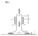
図1は、本発明による方法のために使用可能なノズル2の一実施例の概略横断面図を示す。図示したノズル2は、入口3と、物体もしくはストリップ1の冷却すべき表面に向かい合うように配置された出口5とを有する。入口3と出口5の間に、ノズル2は、好ましくは、入口3へ導かれる容積流Vを出口5へ案内するための領域9を備える。容積流Vは、好ましくは、冷却すべき表面に対して垂直に位置するように出口5に供給される。入口3は、好ましくは、出口5よりも小さい内法の直径もしくは横断面Eを備える。換言すれば、出口5は、入口領域3及び/又はガイド領域9よりも大きい内法の直径もしくは横断面Aを備える。ノズル2もしくはその出口5は、冷却すべき表面の方向に拡大され、特にガイド領域9内をガイド要素7によって移動可能に支承されているか、冷却すべきストリップ1とノズル2の出口5との間の間隔dが可変であるように、冷却すべきストリップ1の表面に対して相対的に支承されている。この場合、ノズル2は、好ましくはガイド7内でスライドする。この運動は、特に、冷却すべき表面に対して垂直に位置する方向Sに行なわれる。ガイド7により、ノズル2は、特に傾倒モーメントに抗して固定されている。方向Sからもしくは方向Sに、好ましくは、ノズル出口5は、冷却流体の容積流Vによって流れを受ける。流体として、一般に液体、特に水又はオイル−水−混合物を問題とすることができる。選択的に、例えば空気又は不活性ガスのような気体による冷却も可能である。但し好ましくは、冷却剤として、一般に液体が使用されるが、それは、気体よりも高い熱伝達係数を実現することができるからである。但し好ましくは、単相の冷却流体だけを使用すべきである。容積流Vが相応に調整される場合、ノズル2は、冷却すべき表面に吸い付く。これは、既に前で説明したように、ベルヌーイの原理又は換言すれば流体力学的パラドックスに従って行なわれる。調整は、ノズル2に供給される容積流Vの圧力又は速度を適合させることによって行なうことができる。
FIG. 1 shows a schematic cross-sectional view of one embodiment of a
ベルヌーイの原理自体は、当業者に知られている。相応の効果が、例えばトラックの傍らを乗用車が通過する場合にも生じるが、両車両が同じ高さに存在する間に、乗用車は、トラックに対して相対的に引き寄せられる。トラックを通過した後、乗用車は、その走行方向に対して横に再び戻るように移動する。追越し中に生じる吸引は、両車両の間の狭められたかつ加速された空気流によって惹起される。ベルヌーイの原理によれば、この狭められ、加速された空気流は、これら車両の残りの周囲内の空気圧に対して相対的な両者車両の間の負圧を生じさせる。但しこの説明は、例示のために役立つにすぎず、限定であると理解すべきでない。 The Bernoulli principle itself is known to those skilled in the art. A corresponding effect occurs, for example, when a passenger car passes by the truck, but the passenger car is pulled relative to the truck while both vehicles are at the same height. After passing the truck, the passenger car moves back again in the direction of travel. The suction that occurs during overtaking is caused by a narrowed and accelerated air flow between the two vehicles. According to Bernoulli's principle, this narrowed and accelerated air flow creates a negative pressure between both vehicles relative to the air pressure in the rest of these vehicles. However, this description is only for illustrative purposes and should not be understood as limiting.
本発明もしくは説明した実施例に関して、出口5から流出する容積流V’が、出口5と冷却すべき表面1の間に十分に高い相対速度を達成した時に吸引効果が生じるので、出口5と冷却すべき表面1の間をながれる容積流V’の圧力は、ノズル2を取り巻く圧力以下へ低下する。この圧力は、大気圧に一致し得る。吸引効果が生じたときに容積流Vを一定に保つと、ベルヌーイの原理に従って、自動的に維持される力バランスがある。冷却すべき表面とノズル出口5の間の間隔dが変更されると、ノズルは、自動的に力バランスの状態の間隔を生じさせる。このような間隔変化は、例えば冷却すべき表面が不規則であることによって、又は、例えばロール表面の変形又はストリップ1の不正確なガイドによって、惹起され得る。同じことが、ロールを冷却するときに、不規則なロール表面に対して当て嵌まる。
With respect to the present invention or the described embodiment, the
一般に、ノズル2もしくは本発明による方法は、ストリップ上側に適用することができるが、ストリップ下側に適用することもできる。
In general, the
図2は、ストリップ1を冷却するための冷却装置10の一実施例の概略横断面図を示す。簡素化のために、同じ又は同様の要素に対して図1におけるのと同じ符号が使用される。図2に図示した装置10は、多数のノズル2を備え、これらノズルは、共に冷却流体容器14によって供給される。冷却装置10は、それぞれ、ストリップ1を冷却するためにストリップ上側とストリップ下側に配置されている。個々のノズル2は、ストリップ走行方向Bに相前後して位置する列の形態で配置されている。各列は、特にストリップ走行方向Bに対して横に延在する。これら列は、ストリップ走行方向Bに対して垂直に位置をずらすことができるので、ストリップ走行方向Bで見て、列の1つによるよりも大きい、ストリップ1の幅の部分がカバーされている。ノズル2は、図1に示したのと同様に、それぞれ、その入口3を介して容積流Vを供給される。この場合、容器14は、冷却流体をノズル2の入口3へ押し込むために、相応に圧力下に置くことができる。ノズル2は、冷却すべき表面に対して垂直にガイド要素7(例えば滑り軸受)によってスライド式に案内されているので、ノズル出口5と冷却すべき表面の間の間隔dは可変である。それにも拘わらず、間隔dは、例えば機械的に制限することができる。冷却すべき表面との衝突を回避するため、装置10、特にノズル2及び/又はガイド要素7は、特にストッパ11を備え、これらストッパは、冷却すべき表面の方向のノズル2の運動を制限する。付加的に、ノズル2は、弾性手段及び/又はバネ要素13によって実質的に、冷却すべき表面に対して垂直に予荷重を受けることができる。
FIG. 2 shows a schematic cross-sectional view of one embodiment of a
更に、一般に、冷却装置10が1つ又は複数の振動装置(図示してない)を有し、この振動装置は、冷却すべき表面に対して平行に各ノズル2を振動させるために形成されているか、装置10の全てのノズル2を共に振動させることが可能である。好ましくは、ノズル2を取り付けた容器14全体の振動が可能である。
Further, in general, the
図3は、部分的に透視した冷却装置10’の一実施例の平面図を示す。この装置10’は、実質的に図2によるものに一致するが、しかしながら、ストリップ走行方向Bに相前後して配置された6つのノズル列が設けられている。図2による装置は、4つのこのような列を備えるに過ぎない。ノズル2は、流体容器14’によって冷却流体を供給される。流体は、容積流V’の形態でそれぞれノズル2の出口5から流出するので、ストリップ1と冷却流体もしくは容積流V’の間で熱伝達が行なわれ得る。図3に図示したように、容積流V’は、好ましくは及び一般に冷却すべき表面に対して実質的に平行に位置する方向に、ノズルの出口5から出る。ノズル出口5が図示した回転対称もしくは円形の形状を備える場合には、出口から出る容積流V’は、実質的に同軸にノズル2から離れるように移動する。
FIG. 3 shows a plan view of one embodiment of the cooling device 10 'partially seen through. This
全般的に、本発明によるノズル2は、例えばスリット状又は円形の形状のように異なった形状を備えることができる。スリット状に形成した場合、ノズル2は、少なくとも冷却すべき表面の幅の一部にわたって、例えばロール又はストリップの幅にわたるように、延在させることができる。
In general, the
但し一般に、ノズル2もしくはノズル出口5の横断面は、冷却すべき表面の移動に基づいて生じる比対称の作用領域に適合させることもできる。
In general, however, the cross section of the
更に、ノズル出口の内法の直径は、好ましくは0.5cm〜10cm又は好ましくは1cm〜5cmの間とすることができる。 Furthermore, the inner diameter of the nozzle outlet can preferably be between 0.5 cm and 10 cm or preferably between 1 cm and 5 cm.
例えば空気又は不活性ガスのような気体で冷却する場合、ノズル2の出口5と冷却すべき表面の間の間隔は、例えば0.1mm〜5mmの間又は好ましくは0.1mm〜3mmの間とすることができる。
When cooling with a gas, for example air or inert gas, the distance between the
例えば水、水混合物又はエマルジョンのような液体で冷却する場合、ノズル2の出口5と冷却すべき表面の間の間隔は、例えば0.5mm〜5mmの間又は好ましくは1mm〜5mmの間又はそれどころか1mm〜2mmの間とすることができる。
When cooling with liquids such as water, water mixtures or emulsions, the distance between the
前記間隔よりもさらに小さい間隔は、通常は有利でない。それは、このような場合には、冷却すべき表面とノズル2の間の衝突の高い危険があるからである。このような衝突は、ノズル2及び/又は冷却すべき表面に損傷を与えることがある。
Spacing smaller than the spacing is usually not advantageous. This is because in such a case there is a high risk of a collision between the surface to be cooled and the
複数のノズルが冷却すべき表面に向かい合うように配置される場合には、これらは、特に互いに、出口5の内法の直径の0.5倍〜5倍又は特に1倍〜2倍に一致する間隔を備える。
If a plurality of nozzles are arranged facing the surface to be cooled, these correspond in particular to each other 0.5 times to 5 times or in particular 1 time to 2 times the inner diameter of the
前記実施例は、特に本発明の良好な理解のために使用され、限定的であると理解すべきでない。本発明の保護範囲は、特許請求の範囲から得られる。 The above examples are used especially for a better understanding of the invention and should not be understood as limiting. The protection scope of the present invention is obtained from the claims.
前記実施例の特徴は、互いに組み合わせること又は互いに交換することができる。 The features of the embodiments can be combined with each other or exchanged with each other.
更に、前記の特徴は、当業者によって、既存の状況又は現在の要求に適合させることができる。 Furthermore, the above features can be adapted to existing situations or current requirements by those skilled in the art.
1 圧延材、鋳造材、ストリップ又は板材
2 ノズル
3 入口
5 出口
7 ガイド要素
9 ガイド領域
10 冷却装置
10’ 冷却装置
11 制限要素
13 予荷重要素/バネ要素/減衰要素
14 流体容器
14’ 流体容器
A 出口の横断面
B ストリップ走行方向
E 入口の横断面
S 冷却すべき表面に対して垂直な方向
V 冷却剤の容積流
V’ ノズルの出口から流出する容積流
d 冷却すべき表面に対するノズルの間隔
DESCRIPTION OF SYMBOLS 1 Rolled material, casting material, strip, or
Claims (14)
ノズル(2)が、少なくとも部分的にガイド(7)内にスライド式に支承され、冷却すべき表面からの出口(5)の間隔(d)が、冷却すべき表面に対して垂直に位置する方向(S)に可変であり、ノズル(2)の入口(3)に供給される冷却流体の容積流(V)は、ノズル(2)がベルヌーイの原理に従って冷却すべき表面に自主的に吸い付くように調整され、間隔(d)が、容積流(V)の調整によって自動的に調整可能であること、を特徴とする方法。 Preparing a nozzle (2) having an inlet (3) and an outlet (5) facing the surface to be cooled, fed to the nozzle (2) via the inlet (3) and via the outlet (5) and a step of supplying a single-phase volumetric flow consisting only of liquid or only gas of the cooling fluid exiting the (2) (V), cast material, in a method for cooling the rolled material (1) or the surface of roll ,
The nozzle (2) is slidably mounted at least partly in the guide (7) and the distance (d) of the outlet (5) from the surface to be cooled is located perpendicular to the surface to be cooled. The volume flow (V) of the cooling fluid, which is variable in direction (S) and supplied to the inlet (3) of the nozzle (2), is independently sucked by the nozzle (2) onto the surface to be cooled according to Bernoulli's principle. And the interval (d) can be adjusted automatically by adjusting the volume flow (V) .
冷却装置(10)は、更に、冷却すべき表面に対して垂直に位置する、ノズル(2)の出口(5)と冷却すべき表面の間の間隔(d)が、0.1mmから5mmの間で可変に調整可能であるように、形成されていることを特徴とする冷却装置。 An inlet (3) having a first internal cross section (E) and a second internal cross section (A) larger than the first cross section (E) facing the surface to be cooled; The surface of a cast material, rolled material (1) or roll for carrying out the method according to any one of claims 1 to 12 , comprising at least one nozzle (2) having an outlet (5). In the cooling device (10) for cooling,
The cooling device (10) further has a distance (d) between the outlet (5) of the nozzle (2) and the surface to be cooled, which is positioned perpendicular to the surface to be cooled, between 0.1 mm and 5 mm. as it is variably adjustable between the cooling apparatus characterized by being formed.
圧延装置が、冷却すべきロール表面を有する少なくとも1つのロールを有し、ノズル(2)の出口(5)が、冷却のためにロール表面に整向されている、又は、
圧延装置が、ストリップ(1)を圧延するために相並んで位置する少なくとも2つのロールスタンドを有し、冷却装置(10)が、両ロールスタンドの間に存在するストリップ(1)の表面を冷却するために両ロールスタンドの間に配置されていること、を特徴とする圧延装置。 In a rolling device for rolling a rolled material having at least one cooling device (10) according to claim 13 ,
The rolling device has at least one roll having a roll surface to be cooled and the outlet (5) of the nozzle (2) is oriented to the roll surface for cooling, or
The rolling device has at least two roll stands positioned side by side for rolling the strip (1), and the cooling device (10) cools the surface of the strip (1) existing between both roll stands. In order to do so, it is arrange | positioned between both roll stands, The rolling apparatus characterized by the above-mentioned.
Applications Claiming Priority (3)
| Application Number | Priority Date | Filing Date | Title |
|---|---|---|---|
| DE102012211454.8 | 2012-07-02 | ||
| DE102012211454.8A DE102012211454A1 (en) | 2012-07-02 | 2012-07-02 | Method and device for cooling surfaces in casting plants, rolling mills or other strip processing lines |
| PCT/EP2013/063866 WO2014006008A1 (en) | 2012-07-02 | 2013-07-01 | Method and device for cooling surfaces in casting installations, rolling installations or other strip processing lines |
Publications (3)
| Publication Number | Publication Date |
|---|---|
| JP2015527199A JP2015527199A (en) | 2015-09-17 |
| JP2015527199A5 JP2015527199A5 (en) | 2015-11-05 |
| JP5840818B2 true JP5840818B2 (en) | 2016-01-06 |
Family
ID=48741150
Family Applications (1)
| Application Number | Title | Priority Date | Filing Date |
|---|---|---|---|
| JP2015519179A Expired - Fee Related JP5840818B2 (en) | 2012-07-02 | 2013-07-01 | Method and apparatus for cooling surfaces in casting equipment, rolling equipment or other strip process lines |
Country Status (8)
| Country | Link |
|---|---|
| US (1) | US9421593B2 (en) |
| EP (1) | EP2866957B1 (en) |
| JP (1) | JP5840818B2 (en) |
| KR (1) | KR101659474B1 (en) |
| CN (1) | CN104602831B (en) |
| DE (1) | DE102012211454A1 (en) |
| RU (1) | RU2612467C2 (en) |
| WO (1) | WO2014006008A1 (en) |
Families Citing this family (8)
| Publication number | Priority date | Publication date | Assignee | Title |
|---|---|---|---|---|
| US10129243B2 (en) | 2013-12-27 | 2018-11-13 | Avaya Inc. | Controlling access to traversal using relays around network address translation (TURN) servers using trusted single-use credentials |
| EP3302837B1 (en) * | 2015-05-29 | 2020-03-11 | voestalpine Stahl GmbH | Method for the homogeneous non-contact temperature control of non-endless surfaces which are to be temperature-controlled, and device therefor |
| EP3515615B1 (en) * | 2016-09-19 | 2020-01-22 | SMS Group GmbH | Roll treatment during operation |
| EP3308868B1 (en) * | 2016-10-17 | 2022-12-07 | Primetals Technologies Austria GmbH | Cooling of a roll of a roll stand |
| CN107746928B (en) * | 2017-11-21 | 2024-04-12 | 上海信鹏印刷器材有限公司 | Continuous tempering device and method for die-cutting knife steel belt |
| CN111372688B (en) * | 2017-12-04 | 2022-03-29 | 日本制铁株式会社 | Surface following nozzle, observation device for surface of moving object, and observation method for surface of moving object |
| KR102403959B1 (en) * | 2017-12-04 | 2022-06-02 | 닛폰세이테츠 가부시키가이샤 | Surface-following nozzle, apparatus for observing the surface of a moving object, and a method for observing the surface of a moving object |
| EP3808466A1 (en) * | 2019-10-16 | 2021-04-21 | Primetals Technologies Germany GmbH | Cooling device with coolant jets with hollow cross-section |
Family Cites Families (21)
| Publication number | Priority date | Publication date | Assignee | Title |
|---|---|---|---|---|
| US2921488A (en) * | 1955-11-23 | 1960-01-19 | United States Steel Corp | Method and apparatus for cooling mill rolls |
| BE851382A (en) * | 1977-02-11 | 1977-05-31 | Centre Rech Metallurgique | IMPROVEMENTS IN METHODS AND DEVICES FOR COMBATING BURDING OF ROLLER CYLINDERS |
| DE2751013C3 (en) | 1977-11-15 | 1981-07-09 | Kleinewefers Gmbh, 4150 Krefeld | Cooling device |
| JPS57156830A (en) * | 1981-03-24 | 1982-09-28 | Kawasaki Steel Corp | Cooling method for rolling material |
| SU1386324A1 (en) | 1985-11-10 | 1988-04-07 | Краматорский Индустриальный Институт | Method of removing scale from the surface of heated metal |
| SU1588781A1 (en) | 1988-06-03 | 1990-08-30 | Донецкий политехнический институт | Method of surface treatment of moving rolled stock |
| CN2035282U (en) * | 1988-07-07 | 1989-04-05 | 冶金工业部钢铁研究总院 | Cooling device for hot-state steel plate |
| DE4116019C2 (en) | 1991-05-16 | 1997-01-23 | Sundwiger Eisen Maschinen | Method and device for cooling a flat material, in particular a metal strip |
| JPH04367313A (en) * | 1991-06-11 | 1992-12-18 | Nippon Steel Corp | Method and device for cooling strip |
| JPH0688134A (en) * | 1992-09-08 | 1994-03-29 | Nippon Steel Corp | Device for cooling strip |
| JP3360889B2 (en) | 1993-09-24 | 2003-01-07 | 石川島播磨重工業株式会社 | Side guide equipment for strip winder |
| JPH07284820A (en) | 1994-04-14 | 1995-10-31 | Hitachi Ltd | Device and method for cooling roll for rolling mill |
| JP3494327B2 (en) * | 1995-10-03 | 2004-02-09 | 株式会社共立合金製作所 | Descaler nozzle |
| DE19718530B4 (en) | 1997-05-02 | 2005-02-03 | Sms Demag Ag | Process for cooling of rolling-cold rolling stock and apparatus for carrying out the method and use of the apparatus |
| JPH11244928A (en) | 1998-03-05 | 1999-09-14 | Nippon Steel Corp | Method for washing metallic strip |
| DE10207584A1 (en) | 2002-02-22 | 2003-09-11 | Vits Maschb Gmbh I Ins | Process for cooling metal strips or plates and cooling device |
| JP2003285114A (en) * | 2002-03-26 | 2003-10-07 | Jfe Steel Kk | Skinpass rolling method of hot-dip galvanizing steel sheet and apparatus for skinpass rolling |
| JP3867073B2 (en) | 2003-10-17 | 2007-01-10 | 新日本製鐵株式会社 | Cooling apparatus and cooling method for hot rolled steel sheet |
| ES2355640T3 (en) * | 2004-08-05 | 2011-03-29 | Kabushiki Kaisha Kobe Seiko Sho | DEPOSIT EXTRACTION DEVICE. |
| US8349247B2 (en) * | 2007-05-11 | 2013-01-08 | Nippon Steel Corporation | Controlled cooling apparatus and cooling method of steel plate |
| JP5646261B2 (en) * | 2010-09-22 | 2014-12-24 | 三菱日立製鉄機械株式会社 | Hot strip strip cooling system |
-
2012
- 2012-07-02 DE DE102012211454.8A patent/DE102012211454A1/en not_active Withdrawn
-
2013
- 2013-07-01 RU RU2015103150A patent/RU2612467C2/en not_active IP Right Cessation
- 2013-07-01 US US14/410,641 patent/US9421593B2/en not_active Expired - Fee Related
- 2013-07-01 WO PCT/EP2013/063866 patent/WO2014006008A1/en active Application Filing
- 2013-07-01 JP JP2015519179A patent/JP5840818B2/en not_active Expired - Fee Related
- 2013-07-01 CN CN201380045786.2A patent/CN104602831B/en active Active
- 2013-07-01 EP EP13732950.4A patent/EP2866957B1/en active Active
- 2013-07-01 KR KR1020157001392A patent/KR101659474B1/en active IP Right Grant
Also Published As
| Publication number | Publication date |
|---|---|
| US9421593B2 (en) | 2016-08-23 |
| EP2866957B1 (en) | 2016-04-27 |
| DE102012211454A1 (en) | 2014-01-02 |
| WO2014006008A1 (en) | 2014-01-09 |
| EP2866957A1 (en) | 2015-05-06 |
| RU2015103150A (en) | 2016-08-20 |
| RU2612467C2 (en) | 2017-03-09 |
| JP2015527199A (en) | 2015-09-17 |
| CN104602831A (en) | 2015-05-06 |
| KR101659474B1 (en) | 2016-09-23 |
| US20150239027A1 (en) | 2015-08-27 |
| CN104602831B (en) | 2017-06-09 |
| KR20150016411A (en) | 2015-02-11 |
Similar Documents
| Publication | Publication Date | Title |
|---|---|---|
| JP5840818B2 (en) | Method and apparatus for cooling surfaces in casting equipment, rolling equipment or other strip process lines | |
| JP6908231B2 (en) | Methods and equipment for uniform non-contact cooling of high temperature non-endless surfaces | |
| JP2015527199A5 (en) | ||
| US8511126B2 (en) | Cooling device for cooling a metal strip | |
| WO2017131204A1 (en) | Secondary cooling method and secondary cooling device for continuously cast slab | |
| BRPI0711142A2 (en) | Hot strip cooling device and cooling method | |
| JP2020517458A (en) | Cooling of rolled material | |
| JP6042559B2 (en) | Equipment for cooling rolled material | |
| JP6538059B2 (en) | Apparatus and method for producing an aerosol, and a focusing component | |
| JP2007284732A (en) | Gas-wiping device | |
| JP5428499B2 (en) | Secondary cooling method for continuous cast slabs with two-fluid mist spray nozzle | |
| JP5597989B2 (en) | Bottom surface cooling device for hot-rolled steel strip | |
| JP2744312B2 (en) | Linear water spray device for cooling metal sheets | |
| Ribeiro et al. | The influence of a bend on drop sizes in horizontal annular two-phase flow | |
| JPS6238745A (en) | Method and apparatus for direct production of thin metallic sheet | |
| JP2006297410A (en) | System and method for cooling thick steel plate | |
| KR20060000901A (en) | Hot rolled strip cooling device with coolant header | |
| JP2015080794A (en) | Apparatus and method for cooling finishing rolling system rolling work roll | |
| KR101532496B1 (en) | Wiping device and hot-dip plating device using same | |
| JP4307357B2 (en) | Header and cooling device | |
| JP2005256055A (en) | Consecutive hot dip metal coating method and its apparatus | |
| JPH079100A (en) | Secondary cooling method in continuous casting | |
| JPH08155528A (en) | Cooler for metallic sheet | |
| US20100101243A1 (en) | Multipart roller | |
| JP4041134B2 (en) | Edge overcoat prevention device for molten metal plating |
Legal Events
| Date | Code | Title | Description |
|---|---|---|---|
| A524 | Written submission of copy of amendment under section 19 (pct) |
Free format text: JAPANESE INTERMEDIATE CODE: A524 Effective date: 20150827 |
|
| A521 | Written amendment |
Free format text: JAPANESE INTERMEDIATE CODE: A523 Effective date: 20150828 |
|
| TRDD | Decision of grant or rejection written | ||
| A01 | Written decision to grant a patent or to grant a registration (utility model) |
Free format text: JAPANESE INTERMEDIATE CODE: A01 Effective date: 20151014 |
|
| A61 | First payment of annual fees (during grant procedure) |
Free format text: JAPANESE INTERMEDIATE CODE: A61 Effective date: 20151111 |
|
| R150 | Certificate of patent or registration of utility model |
Ref document number: 5840818 Country of ref document: JP Free format text: JAPANESE INTERMEDIATE CODE: R150 |
|
| R250 | Receipt of annual fees |
Free format text: JAPANESE INTERMEDIATE CODE: R250 |
|
| R250 | Receipt of annual fees |
Free format text: JAPANESE INTERMEDIATE CODE: R250 |
|
| LAPS | Cancellation because of no payment of annual fees |