JP5834463B2 - Torque control device and non-contact charging system - Google Patents
Torque control device and non-contact charging system Download PDFInfo
- Publication number
- JP5834463B2 JP5834463B2 JP2011095331A JP2011095331A JP5834463B2 JP 5834463 B2 JP5834463 B2 JP 5834463B2 JP 2011095331 A JP2011095331 A JP 2011095331A JP 2011095331 A JP2011095331 A JP 2011095331A JP 5834463 B2 JP5834463 B2 JP 5834463B2
- Authority
- JP
- Japan
- Prior art keywords
- torque
- vehicle
- power
- coil
- accelerator opening
- Prior art date
- Legal status (The legal status is an assumption and is not a legal conclusion. Google has not performed a legal analysis and makes no representation as to the accuracy of the status listed.)
- Active
Links
- 230000005540 biological transmission Effects 0.000 claims description 64
- 238000001514 detection method Methods 0.000 claims description 21
- 238000013459 approach Methods 0.000 claims description 19
- 230000008878 coupling Effects 0.000 claims description 7
- 238000010168 coupling process Methods 0.000 claims description 7
- 238000005859 coupling reaction Methods 0.000 claims description 7
- 238000004891 communication Methods 0.000 description 27
- 230000007423 decrease Effects 0.000 description 6
- 238000010586 diagram Methods 0.000 description 5
- 238000000034 method Methods 0.000 description 4
- 238000004804 winding Methods 0.000 description 4
- 230000004043 responsiveness Effects 0.000 description 3
- 238000009434 installation Methods 0.000 description 2
- 230000008859 change Effects 0.000 description 1
- 230000000694 effects Effects 0.000 description 1
- 230000005674 electromagnetic induction Effects 0.000 description 1
- 230000008569 process Effects 0.000 description 1
- 230000004044 response Effects 0.000 description 1
- 230000007704 transition Effects 0.000 description 1
Images


Classifications
-
- B—PERFORMING OPERATIONS; TRANSPORTING
- B60—VEHICLES IN GENERAL
- B60L—PROPULSION OF ELECTRICALLY-PROPELLED VEHICLES; SUPPLYING ELECTRIC POWER FOR AUXILIARY EQUIPMENT OF ELECTRICALLY-PROPELLED VEHICLES; ELECTRODYNAMIC BRAKE SYSTEMS FOR VEHICLES IN GENERAL; MAGNETIC SUSPENSION OR LEVITATION FOR VEHICLES; MONITORING OPERATING VARIABLES OF ELECTRICALLY-PROPELLED VEHICLES; ELECTRIC SAFETY DEVICES FOR ELECTRICALLY-PROPELLED VEHICLES
- B60L53/00—Methods of charging batteries, specially adapted for electric vehicles; Charging stations or on-board charging equipment therefor; Exchange of energy storage elements in electric vehicles
- B60L53/30—Constructional details of charging stations
-
- B—PERFORMING OPERATIONS; TRANSPORTING
- B60—VEHICLES IN GENERAL
- B60L—PROPULSION OF ELECTRICALLY-PROPELLED VEHICLES; SUPPLYING ELECTRIC POWER FOR AUXILIARY EQUIPMENT OF ELECTRICALLY-PROPELLED VEHICLES; ELECTRODYNAMIC BRAKE SYSTEMS FOR VEHICLES IN GENERAL; MAGNETIC SUSPENSION OR LEVITATION FOR VEHICLES; MONITORING OPERATING VARIABLES OF ELECTRICALLY-PROPELLED VEHICLES; ELECTRIC SAFETY DEVICES FOR ELECTRICALLY-PROPELLED VEHICLES
- B60L15/00—Methods, circuits, or devices for controlling the traction-motor speed of electrically-propelled vehicles
- B60L15/20—Methods, circuits, or devices for controlling the traction-motor speed of electrically-propelled vehicles for control of the vehicle or its driving motor to achieve a desired performance, e.g. speed, torque, programmed variation of speed
-
- B—PERFORMING OPERATIONS; TRANSPORTING
- B60—VEHICLES IN GENERAL
- B60L—PROPULSION OF ELECTRICALLY-PROPELLED VEHICLES; SUPPLYING ELECTRIC POWER FOR AUXILIARY EQUIPMENT OF ELECTRICALLY-PROPELLED VEHICLES; ELECTRODYNAMIC BRAKE SYSTEMS FOR VEHICLES IN GENERAL; MAGNETIC SUSPENSION OR LEVITATION FOR VEHICLES; MONITORING OPERATING VARIABLES OF ELECTRICALLY-PROPELLED VEHICLES; ELECTRIC SAFETY DEVICES FOR ELECTRICALLY-PROPELLED VEHICLES
- B60L15/00—Methods, circuits, or devices for controlling the traction-motor speed of electrically-propelled vehicles
- B60L15/40—Adaptation of control equipment on vehicle for remote actuation from a stationary place
-
- B—PERFORMING OPERATIONS; TRANSPORTING
- B60—VEHICLES IN GENERAL
- B60L—PROPULSION OF ELECTRICALLY-PROPELLED VEHICLES; SUPPLYING ELECTRIC POWER FOR AUXILIARY EQUIPMENT OF ELECTRICALLY-PROPELLED VEHICLES; ELECTRODYNAMIC BRAKE SYSTEMS FOR VEHICLES IN GENERAL; MAGNETIC SUSPENSION OR LEVITATION FOR VEHICLES; MONITORING OPERATING VARIABLES OF ELECTRICALLY-PROPELLED VEHICLES; ELECTRIC SAFETY DEVICES FOR ELECTRICALLY-PROPELLED VEHICLES
- B60L50/00—Electric propulsion with power supplied within the vehicle
- B60L50/50—Electric propulsion with power supplied within the vehicle using propulsion power supplied by batteries or fuel cells
- B60L50/51—Electric propulsion with power supplied within the vehicle using propulsion power supplied by batteries or fuel cells characterised by AC-motors
-
- B—PERFORMING OPERATIONS; TRANSPORTING
- B60—VEHICLES IN GENERAL
- B60L—PROPULSION OF ELECTRICALLY-PROPELLED VEHICLES; SUPPLYING ELECTRIC POWER FOR AUXILIARY EQUIPMENT OF ELECTRICALLY-PROPELLED VEHICLES; ELECTRODYNAMIC BRAKE SYSTEMS FOR VEHICLES IN GENERAL; MAGNETIC SUSPENSION OR LEVITATION FOR VEHICLES; MONITORING OPERATING VARIABLES OF ELECTRICALLY-PROPELLED VEHICLES; ELECTRIC SAFETY DEVICES FOR ELECTRICALLY-PROPELLED VEHICLES
- B60L53/00—Methods of charging batteries, specially adapted for electric vehicles; Charging stations or on-board charging equipment therefor; Exchange of energy storage elements in electric vehicles
- B60L53/10—Methods of charging batteries, specially adapted for electric vehicles; Charging stations or on-board charging equipment therefor; Exchange of energy storage elements in electric vehicles characterised by the energy transfer between the charging station and the vehicle
- B60L53/12—Inductive energy transfer
- B60L53/122—Circuits or methods for driving the primary coil, e.g. supplying electric power to the coil
-
- B—PERFORMING OPERATIONS; TRANSPORTING
- B60—VEHICLES IN GENERAL
- B60L—PROPULSION OF ELECTRICALLY-PROPELLED VEHICLES; SUPPLYING ELECTRIC POWER FOR AUXILIARY EQUIPMENT OF ELECTRICALLY-PROPELLED VEHICLES; ELECTRODYNAMIC BRAKE SYSTEMS FOR VEHICLES IN GENERAL; MAGNETIC SUSPENSION OR LEVITATION FOR VEHICLES; MONITORING OPERATING VARIABLES OF ELECTRICALLY-PROPELLED VEHICLES; ELECTRIC SAFETY DEVICES FOR ELECTRICALLY-PROPELLED VEHICLES
- B60L53/00—Methods of charging batteries, specially adapted for electric vehicles; Charging stations or on-board charging equipment therefor; Exchange of energy storage elements in electric vehicles
- B60L53/10—Methods of charging batteries, specially adapted for electric vehicles; Charging stations or on-board charging equipment therefor; Exchange of energy storage elements in electric vehicles characterised by the energy transfer between the charging station and the vehicle
- B60L53/12—Inductive energy transfer
- B60L53/126—Methods for pairing a vehicle and a charging station, e.g. establishing a one-to-one relation between a wireless power transmitter and a wireless power receiver
-
- B—PERFORMING OPERATIONS; TRANSPORTING
- B60—VEHICLES IN GENERAL
- B60L—PROPULSION OF ELECTRICALLY-PROPELLED VEHICLES; SUPPLYING ELECTRIC POWER FOR AUXILIARY EQUIPMENT OF ELECTRICALLY-PROPELLED VEHICLES; ELECTRODYNAMIC BRAKE SYSTEMS FOR VEHICLES IN GENERAL; MAGNETIC SUSPENSION OR LEVITATION FOR VEHICLES; MONITORING OPERATING VARIABLES OF ELECTRICALLY-PROPELLED VEHICLES; ELECTRIC SAFETY DEVICES FOR ELECTRICALLY-PROPELLED VEHICLES
- B60L53/00—Methods of charging batteries, specially adapted for electric vehicles; Charging stations or on-board charging equipment therefor; Exchange of energy storage elements in electric vehicles
- B60L53/30—Constructional details of charging stations
- B60L53/35—Means for automatic or assisted adjustment of the relative position of charging devices and vehicles
- B60L53/36—Means for automatic or assisted adjustment of the relative position of charging devices and vehicles by positioning the vehicle
-
- B—PERFORMING OPERATIONS; TRANSPORTING
- B60—VEHICLES IN GENERAL
- B60L—PROPULSION OF ELECTRICALLY-PROPELLED VEHICLES; SUPPLYING ELECTRIC POWER FOR AUXILIARY EQUIPMENT OF ELECTRICALLY-PROPELLED VEHICLES; ELECTRODYNAMIC BRAKE SYSTEMS FOR VEHICLES IN GENERAL; MAGNETIC SUSPENSION OR LEVITATION FOR VEHICLES; MONITORING OPERATING VARIABLES OF ELECTRICALLY-PROPELLED VEHICLES; ELECTRIC SAFETY DEVICES FOR ELECTRICALLY-PROPELLED VEHICLES
- B60L53/00—Methods of charging batteries, specially adapted for electric vehicles; Charging stations or on-board charging equipment therefor; Exchange of energy storage elements in electric vehicles
- B60L53/30—Constructional details of charging stations
- B60L53/35—Means for automatic or assisted adjustment of the relative position of charging devices and vehicles
- B60L53/37—Means for automatic or assisted adjustment of the relative position of charging devices and vehicles using optical position determination, e.g. using cameras
-
- B—PERFORMING OPERATIONS; TRANSPORTING
- B60—VEHICLES IN GENERAL
- B60L—PROPULSION OF ELECTRICALLY-PROPELLED VEHICLES; SUPPLYING ELECTRIC POWER FOR AUXILIARY EQUIPMENT OF ELECTRICALLY-PROPELLED VEHICLES; ELECTRODYNAMIC BRAKE SYSTEMS FOR VEHICLES IN GENERAL; MAGNETIC SUSPENSION OR LEVITATION FOR VEHICLES; MONITORING OPERATING VARIABLES OF ELECTRICALLY-PROPELLED VEHICLES; ELECTRIC SAFETY DEVICES FOR ELECTRICALLY-PROPELLED VEHICLES
- B60L53/00—Methods of charging batteries, specially adapted for electric vehicles; Charging stations or on-board charging equipment therefor; Exchange of energy storage elements in electric vehicles
- B60L53/30—Constructional details of charging stations
- B60L53/35—Means for automatic or assisted adjustment of the relative position of charging devices and vehicles
- B60L53/38—Means for automatic or assisted adjustment of the relative position of charging devices and vehicles specially adapted for charging by inductive energy transfer
-
- B—PERFORMING OPERATIONS; TRANSPORTING
- B60—VEHICLES IN GENERAL
- B60L—PROPULSION OF ELECTRICALLY-PROPELLED VEHICLES; SUPPLYING ELECTRIC POWER FOR AUXILIARY EQUIPMENT OF ELECTRICALLY-PROPELLED VEHICLES; ELECTRODYNAMIC BRAKE SYSTEMS FOR VEHICLES IN GENERAL; MAGNETIC SUSPENSION OR LEVITATION FOR VEHICLES; MONITORING OPERATING VARIABLES OF ELECTRICALLY-PROPELLED VEHICLES; ELECTRIC SAFETY DEVICES FOR ELECTRICALLY-PROPELLED VEHICLES
- B60L53/00—Methods of charging batteries, specially adapted for electric vehicles; Charging stations or on-board charging equipment therefor; Exchange of energy storage elements in electric vehicles
- B60L53/60—Monitoring or controlling charging stations
- B60L53/65—Monitoring or controlling charging stations involving identification of vehicles or their battery types
-
- H—ELECTRICITY
- H01—ELECTRIC ELEMENTS
- H01M—PROCESSES OR MEANS, e.g. BATTERIES, FOR THE DIRECT CONVERSION OF CHEMICAL ENERGY INTO ELECTRICAL ENERGY
- H01M10/00—Secondary cells; Manufacture thereof
- H01M10/42—Methods or arrangements for servicing or maintenance of secondary cells or secondary half-cells
- H01M10/46—Accumulators structurally combined with charging apparatus
-
- H—ELECTRICITY
- H02—GENERATION; CONVERSION OR DISTRIBUTION OF ELECTRIC POWER
- H02J—CIRCUIT ARRANGEMENTS OR SYSTEMS FOR SUPPLYING OR DISTRIBUTING ELECTRIC POWER; SYSTEMS FOR STORING ELECTRIC ENERGY
- H02J50/00—Circuit arrangements or systems for wireless supply or distribution of electric power
- H02J50/10—Circuit arrangements or systems for wireless supply or distribution of electric power using inductive coupling
-
- H—ELECTRICITY
- H02—GENERATION; CONVERSION OR DISTRIBUTION OF ELECTRIC POWER
- H02J—CIRCUIT ARRANGEMENTS OR SYSTEMS FOR SUPPLYING OR DISTRIBUTING ELECTRIC POWER; SYSTEMS FOR STORING ELECTRIC ENERGY
- H02J50/00—Circuit arrangements or systems for wireless supply or distribution of electric power
- H02J50/15—Circuit arrangements or systems for wireless supply or distribution of electric power using ultrasonic waves
-
- H—ELECTRICITY
- H02—GENERATION; CONVERSION OR DISTRIBUTION OF ELECTRIC POWER
- H02J—CIRCUIT ARRANGEMENTS OR SYSTEMS FOR SUPPLYING OR DISTRIBUTING ELECTRIC POWER; SYSTEMS FOR STORING ELECTRIC ENERGY
- H02J50/00—Circuit arrangements or systems for wireless supply or distribution of electric power
- H02J50/20—Circuit arrangements or systems for wireless supply or distribution of electric power using microwaves or radio frequency waves
-
- H—ELECTRICITY
- H02—GENERATION; CONVERSION OR DISTRIBUTION OF ELECTRIC POWER
- H02J—CIRCUIT ARRANGEMENTS OR SYSTEMS FOR SUPPLYING OR DISTRIBUTING ELECTRIC POWER; SYSTEMS FOR STORING ELECTRIC ENERGY
- H02J50/00—Circuit arrangements or systems for wireless supply or distribution of electric power
- H02J50/80—Circuit arrangements or systems for wireless supply or distribution of electric power involving the exchange of data, concerning supply or distribution of electric power, between transmitting devices and receiving devices
-
- H—ELECTRICITY
- H02—GENERATION; CONVERSION OR DISTRIBUTION OF ELECTRIC POWER
- H02J—CIRCUIT ARRANGEMENTS OR SYSTEMS FOR SUPPLYING OR DISTRIBUTING ELECTRIC POWER; SYSTEMS FOR STORING ELECTRIC ENERGY
- H02J50/00—Circuit arrangements or systems for wireless supply or distribution of electric power
- H02J50/90—Circuit arrangements or systems for wireless supply or distribution of electric power involving detection or optimisation of position, e.g. alignment
-
- B—PERFORMING OPERATIONS; TRANSPORTING
- B60—VEHICLES IN GENERAL
- B60L—PROPULSION OF ELECTRICALLY-PROPELLED VEHICLES; SUPPLYING ELECTRIC POWER FOR AUXILIARY EQUIPMENT OF ELECTRICALLY-PROPELLED VEHICLES; ELECTRODYNAMIC BRAKE SYSTEMS FOR VEHICLES IN GENERAL; MAGNETIC SUSPENSION OR LEVITATION FOR VEHICLES; MONITORING OPERATING VARIABLES OF ELECTRICALLY-PROPELLED VEHICLES; ELECTRIC SAFETY DEVICES FOR ELECTRICALLY-PROPELLED VEHICLES
- B60L2210/00—Converter types
- B60L2210/10—DC to DC converters
-
- B—PERFORMING OPERATIONS; TRANSPORTING
- B60—VEHICLES IN GENERAL
- B60L—PROPULSION OF ELECTRICALLY-PROPELLED VEHICLES; SUPPLYING ELECTRIC POWER FOR AUXILIARY EQUIPMENT OF ELECTRICALLY-PROPELLED VEHICLES; ELECTRODYNAMIC BRAKE SYSTEMS FOR VEHICLES IN GENERAL; MAGNETIC SUSPENSION OR LEVITATION FOR VEHICLES; MONITORING OPERATING VARIABLES OF ELECTRICALLY-PROPELLED VEHICLES; ELECTRIC SAFETY DEVICES FOR ELECTRICALLY-PROPELLED VEHICLES
- B60L2210/00—Converter types
- B60L2210/30—AC to DC converters
-
- B—PERFORMING OPERATIONS; TRANSPORTING
- B60—VEHICLES IN GENERAL
- B60L—PROPULSION OF ELECTRICALLY-PROPELLED VEHICLES; SUPPLYING ELECTRIC POWER FOR AUXILIARY EQUIPMENT OF ELECTRICALLY-PROPELLED VEHICLES; ELECTRODYNAMIC BRAKE SYSTEMS FOR VEHICLES IN GENERAL; MAGNETIC SUSPENSION OR LEVITATION FOR VEHICLES; MONITORING OPERATING VARIABLES OF ELECTRICALLY-PROPELLED VEHICLES; ELECTRIC SAFETY DEVICES FOR ELECTRICALLY-PROPELLED VEHICLES
- B60L2210/00—Converter types
- B60L2210/40—DC to AC converters
-
- B—PERFORMING OPERATIONS; TRANSPORTING
- B60—VEHICLES IN GENERAL
- B60L—PROPULSION OF ELECTRICALLY-PROPELLED VEHICLES; SUPPLYING ELECTRIC POWER FOR AUXILIARY EQUIPMENT OF ELECTRICALLY-PROPELLED VEHICLES; ELECTRODYNAMIC BRAKE SYSTEMS FOR VEHICLES IN GENERAL; MAGNETIC SUSPENSION OR LEVITATION FOR VEHICLES; MONITORING OPERATING VARIABLES OF ELECTRICALLY-PROPELLED VEHICLES; ELECTRIC SAFETY DEVICES FOR ELECTRICALLY-PROPELLED VEHICLES
- B60L2240/00—Control parameters of input or output; Target parameters
- B60L2240/10—Vehicle control parameters
- B60L2240/12—Speed
-
- B—PERFORMING OPERATIONS; TRANSPORTING
- B60—VEHICLES IN GENERAL
- B60L—PROPULSION OF ELECTRICALLY-PROPELLED VEHICLES; SUPPLYING ELECTRIC POWER FOR AUXILIARY EQUIPMENT OF ELECTRICALLY-PROPELLED VEHICLES; ELECTRODYNAMIC BRAKE SYSTEMS FOR VEHICLES IN GENERAL; MAGNETIC SUSPENSION OR LEVITATION FOR VEHICLES; MONITORING OPERATING VARIABLES OF ELECTRICALLY-PROPELLED VEHICLES; ELECTRIC SAFETY DEVICES FOR ELECTRICALLY-PROPELLED VEHICLES
- B60L2240/00—Control parameters of input or output; Target parameters
- B60L2240/10—Vehicle control parameters
- B60L2240/32—Driving direction
-
- B—PERFORMING OPERATIONS; TRANSPORTING
- B60—VEHICLES IN GENERAL
- B60L—PROPULSION OF ELECTRICALLY-PROPELLED VEHICLES; SUPPLYING ELECTRIC POWER FOR AUXILIARY EQUIPMENT OF ELECTRICALLY-PROPELLED VEHICLES; ELECTRODYNAMIC BRAKE SYSTEMS FOR VEHICLES IN GENERAL; MAGNETIC SUSPENSION OR LEVITATION FOR VEHICLES; MONITORING OPERATING VARIABLES OF ELECTRICALLY-PROPELLED VEHICLES; ELECTRIC SAFETY DEVICES FOR ELECTRICALLY-PROPELLED VEHICLES
- B60L2240/00—Control parameters of input or output; Target parameters
- B60L2240/40—Drive Train control parameters
- B60L2240/42—Drive Train control parameters related to electric machines
- B60L2240/421—Speed
-
- B—PERFORMING OPERATIONS; TRANSPORTING
- B60—VEHICLES IN GENERAL
- B60L—PROPULSION OF ELECTRICALLY-PROPELLED VEHICLES; SUPPLYING ELECTRIC POWER FOR AUXILIARY EQUIPMENT OF ELECTRICALLY-PROPELLED VEHICLES; ELECTRODYNAMIC BRAKE SYSTEMS FOR VEHICLES IN GENERAL; MAGNETIC SUSPENSION OR LEVITATION FOR VEHICLES; MONITORING OPERATING VARIABLES OF ELECTRICALLY-PROPELLED VEHICLES; ELECTRIC SAFETY DEVICES FOR ELECTRICALLY-PROPELLED VEHICLES
- B60L2240/00—Control parameters of input or output; Target parameters
- B60L2240/40—Drive Train control parameters
- B60L2240/42—Drive Train control parameters related to electric machines
- B60L2240/423—Torque
-
- B—PERFORMING OPERATIONS; TRANSPORTING
- B60—VEHICLES IN GENERAL
- B60L—PROPULSION OF ELECTRICALLY-PROPELLED VEHICLES; SUPPLYING ELECTRIC POWER FOR AUXILIARY EQUIPMENT OF ELECTRICALLY-PROPELLED VEHICLES; ELECTRODYNAMIC BRAKE SYSTEMS FOR VEHICLES IN GENERAL; MAGNETIC SUSPENSION OR LEVITATION FOR VEHICLES; MONITORING OPERATING VARIABLES OF ELECTRICALLY-PROPELLED VEHICLES; ELECTRIC SAFETY DEVICES FOR ELECTRICALLY-PROPELLED VEHICLES
- B60L2250/00—Driver interactions
- B60L2250/26—Driver interactions by pedal actuation
-
- B—PERFORMING OPERATIONS; TRANSPORTING
- B60—VEHICLES IN GENERAL
- B60W—CONJOINT CONTROL OF VEHICLE SUB-UNITS OF DIFFERENT TYPE OR DIFFERENT FUNCTION; CONTROL SYSTEMS SPECIALLY ADAPTED FOR HYBRID VEHICLES; ROAD VEHICLE DRIVE CONTROL SYSTEMS FOR PURPOSES NOT RELATED TO THE CONTROL OF A PARTICULAR SUB-UNIT
- B60W30/00—Purposes of road vehicle drive control systems not related to the control of a particular sub-unit, e.g. of systems using conjoint control of vehicle sub-units
- B60W30/06—Automatic manoeuvring for parking
-
- H—ELECTRICITY
- H01—ELECTRIC ELEMENTS
- H01M—PROCESSES OR MEANS, e.g. BATTERIES, FOR THE DIRECT CONVERSION OF CHEMICAL ENERGY INTO ELECTRICAL ENERGY
- H01M2220/00—Batteries for particular applications
- H01M2220/20—Batteries in motive systems, e.g. vehicle, ship, plane
-
- H—ELECTRICITY
- H02—GENERATION; CONVERSION OR DISTRIBUTION OF ELECTRIC POWER
- H02J—CIRCUIT ARRANGEMENTS OR SYSTEMS FOR SUPPLYING OR DISTRIBUTING ELECTRIC POWER; SYSTEMS FOR STORING ELECTRIC ENERGY
- H02J2310/00—The network for supplying or distributing electric power characterised by its spatial reach or by the load
- H02J2310/40—The network being an on-board power network, i.e. within a vehicle
- H02J2310/48—The network being an on-board power network, i.e. within a vehicle for electric vehicles [EV] or hybrid vehicles [HEV]
-
- Y—GENERAL TAGGING OF NEW TECHNOLOGICAL DEVELOPMENTS; GENERAL TAGGING OF CROSS-SECTIONAL TECHNOLOGIES SPANNING OVER SEVERAL SECTIONS OF THE IPC; TECHNICAL SUBJECTS COVERED BY FORMER USPC CROSS-REFERENCE ART COLLECTIONS [XRACs] AND DIGESTS
- Y02—TECHNOLOGIES OR APPLICATIONS FOR MITIGATION OR ADAPTATION AGAINST CLIMATE CHANGE
- Y02E—REDUCTION OF GREENHOUSE GAS [GHG] EMISSIONS, RELATED TO ENERGY GENERATION, TRANSMISSION OR DISTRIBUTION
- Y02E60/00—Enabling technologies; Technologies with a potential or indirect contribution to GHG emissions mitigation
- Y02E60/10—Energy storage using batteries
-
- Y—GENERAL TAGGING OF NEW TECHNOLOGICAL DEVELOPMENTS; GENERAL TAGGING OF CROSS-SECTIONAL TECHNOLOGIES SPANNING OVER SEVERAL SECTIONS OF THE IPC; TECHNICAL SUBJECTS COVERED BY FORMER USPC CROSS-REFERENCE ART COLLECTIONS [XRACs] AND DIGESTS
- Y02—TECHNOLOGIES OR APPLICATIONS FOR MITIGATION OR ADAPTATION AGAINST CLIMATE CHANGE
- Y02T—CLIMATE CHANGE MITIGATION TECHNOLOGIES RELATED TO TRANSPORTATION
- Y02T10/00—Road transport of goods or passengers
- Y02T10/60—Other road transportation technologies with climate change mitigation effect
- Y02T10/64—Electric machine technologies in electromobility
-
- Y—GENERAL TAGGING OF NEW TECHNOLOGICAL DEVELOPMENTS; GENERAL TAGGING OF CROSS-SECTIONAL TECHNOLOGIES SPANNING OVER SEVERAL SECTIONS OF THE IPC; TECHNICAL SUBJECTS COVERED BY FORMER USPC CROSS-REFERENCE ART COLLECTIONS [XRACs] AND DIGESTS
- Y02—TECHNOLOGIES OR APPLICATIONS FOR MITIGATION OR ADAPTATION AGAINST CLIMATE CHANGE
- Y02T—CLIMATE CHANGE MITIGATION TECHNOLOGIES RELATED TO TRANSPORTATION
- Y02T10/00—Road transport of goods or passengers
- Y02T10/60—Other road transportation technologies with climate change mitigation effect
- Y02T10/70—Energy storage systems for electromobility, e.g. batteries
-
- Y—GENERAL TAGGING OF NEW TECHNOLOGICAL DEVELOPMENTS; GENERAL TAGGING OF CROSS-SECTIONAL TECHNOLOGIES SPANNING OVER SEVERAL SECTIONS OF THE IPC; TECHNICAL SUBJECTS COVERED BY FORMER USPC CROSS-REFERENCE ART COLLECTIONS [XRACs] AND DIGESTS
- Y02—TECHNOLOGIES OR APPLICATIONS FOR MITIGATION OR ADAPTATION AGAINST CLIMATE CHANGE
- Y02T—CLIMATE CHANGE MITIGATION TECHNOLOGIES RELATED TO TRANSPORTATION
- Y02T10/00—Road transport of goods or passengers
- Y02T10/60—Other road transportation technologies with climate change mitigation effect
- Y02T10/7072—Electromobility specific charging systems or methods for batteries, ultracapacitors, supercapacitors or double-layer capacitors
-
- Y—GENERAL TAGGING OF NEW TECHNOLOGICAL DEVELOPMENTS; GENERAL TAGGING OF CROSS-SECTIONAL TECHNOLOGIES SPANNING OVER SEVERAL SECTIONS OF THE IPC; TECHNICAL SUBJECTS COVERED BY FORMER USPC CROSS-REFERENCE ART COLLECTIONS [XRACs] AND DIGESTS
- Y02—TECHNOLOGIES OR APPLICATIONS FOR MITIGATION OR ADAPTATION AGAINST CLIMATE CHANGE
- Y02T—CLIMATE CHANGE MITIGATION TECHNOLOGIES RELATED TO TRANSPORTATION
- Y02T10/00—Road transport of goods or passengers
- Y02T10/60—Other road transportation technologies with climate change mitigation effect
- Y02T10/72—Electric energy management in electromobility
-
- Y—GENERAL TAGGING OF NEW TECHNOLOGICAL DEVELOPMENTS; GENERAL TAGGING OF CROSS-SECTIONAL TECHNOLOGIES SPANNING OVER SEVERAL SECTIONS OF THE IPC; TECHNICAL SUBJECTS COVERED BY FORMER USPC CROSS-REFERENCE ART COLLECTIONS [XRACs] AND DIGESTS
- Y02—TECHNOLOGIES OR APPLICATIONS FOR MITIGATION OR ADAPTATION AGAINST CLIMATE CHANGE
- Y02T—CLIMATE CHANGE MITIGATION TECHNOLOGIES RELATED TO TRANSPORTATION
- Y02T90/00—Enabling technologies or technologies with a potential or indirect contribution to GHG emissions mitigation
- Y02T90/10—Technologies relating to charging of electric vehicles
- Y02T90/12—Electric charging stations
-
- Y—GENERAL TAGGING OF NEW TECHNOLOGICAL DEVELOPMENTS; GENERAL TAGGING OF CROSS-SECTIONAL TECHNOLOGIES SPANNING OVER SEVERAL SECTIONS OF THE IPC; TECHNICAL SUBJECTS COVERED BY FORMER USPC CROSS-REFERENCE ART COLLECTIONS [XRACs] AND DIGESTS
- Y02—TECHNOLOGIES OR APPLICATIONS FOR MITIGATION OR ADAPTATION AGAINST CLIMATE CHANGE
- Y02T—CLIMATE CHANGE MITIGATION TECHNOLOGIES RELATED TO TRANSPORTATION
- Y02T90/00—Enabling technologies or technologies with a potential or indirect contribution to GHG emissions mitigation
- Y02T90/10—Technologies relating to charging of electric vehicles
- Y02T90/14—Plug-in electric vehicles
-
- Y—GENERAL TAGGING OF NEW TECHNOLOGICAL DEVELOPMENTS; GENERAL TAGGING OF CROSS-SECTIONAL TECHNOLOGIES SPANNING OVER SEVERAL SECTIONS OF THE IPC; TECHNICAL SUBJECTS COVERED BY FORMER USPC CROSS-REFERENCE ART COLLECTIONS [XRACs] AND DIGESTS
- Y02—TECHNOLOGIES OR APPLICATIONS FOR MITIGATION OR ADAPTATION AGAINST CLIMATE CHANGE
- Y02T—CLIMATE CHANGE MITIGATION TECHNOLOGIES RELATED TO TRANSPORTATION
- Y02T90/00—Enabling technologies or technologies with a potential or indirect contribution to GHG emissions mitigation
- Y02T90/10—Technologies relating to charging of electric vehicles
- Y02T90/16—Information or communication technologies improving the operation of electric vehicles
- Y02T90/167—Systems integrating technologies related to power network operation and communication or information technologies for supporting the interoperability of electric or hybrid vehicles, i.e. smartgrids as interface for battery charging of electric vehicles [EV] or hybrid vehicles [HEV]
-
- Y—GENERAL TAGGING OF NEW TECHNOLOGICAL DEVELOPMENTS; GENERAL TAGGING OF CROSS-SECTIONAL TECHNOLOGIES SPANNING OVER SEVERAL SECTIONS OF THE IPC; TECHNICAL SUBJECTS COVERED BY FORMER USPC CROSS-REFERENCE ART COLLECTIONS [XRACs] AND DIGESTS
- Y04—INFORMATION OR COMMUNICATION TECHNOLOGIES HAVING AN IMPACT ON OTHER TECHNOLOGY AREAS
- Y04S—SYSTEMS INTEGRATING TECHNOLOGIES RELATED TO POWER NETWORK OPERATION, COMMUNICATION OR INFORMATION TECHNOLOGIES FOR IMPROVING THE ELECTRICAL POWER GENERATION, TRANSMISSION, DISTRIBUTION, MANAGEMENT OR USAGE, i.e. SMART GRIDS
- Y04S30/00—Systems supporting specific end-user applications in the sector of transportation
- Y04S30/10—Systems supporting the interoperability of electric or hybrid vehicles
- Y04S30/14—Details associated with the interoperability, e.g. vehicle recognition, authentication, identification or billing
Landscapes
- Engineering & Computer Science (AREA)
- Power Engineering (AREA)
- Transportation (AREA)
- Mechanical Engineering (AREA)
- Computer Networks & Wireless Communication (AREA)
- Sustainable Energy (AREA)
- Life Sciences & Earth Sciences (AREA)
- Sustainable Development (AREA)
- Chemical & Material Sciences (AREA)
- Chemical Kinetics & Catalysis (AREA)
- Electrochemistry (AREA)
- General Chemical & Material Sciences (AREA)
- Manufacturing & Machinery (AREA)
- Electric Propulsion And Braking For Vehicles (AREA)
- Charge And Discharge Circuits For Batteries Or The Like (AREA)
- Secondary Cells (AREA)
- Current-Collector Devices For Electrically Propelled Vehicles (AREA)
Description
本発明は、トルク制御装置及び非接触充電システムに関するものである。 The present invention relates to a torque control device and a contactless charging system.
所定の距離を隔てて形成される空隙を介して、互いに対向して配置され、且つそれぞれ所定の口径と形状であり、給電時に上下等で対称の同一構造をなす給電コイルと受電コイルとを有する非接触給電装置において、受電側である電気自動車に、充電用コントローラと、バッテリーとを備え、当該給電コイルから受電コイルへの給電よりバッテリーを充電するものが知られている(特許文献1)。 A power supply coil and a power reception coil are disposed opposite to each other through a gap formed at a predetermined distance, and each have a predetermined aperture and shape, and have the same symmetrical structure in the vertical direction during power supply. As a non-contact power supply device, a device that includes a charging controller and a battery in an electric vehicle on the power receiving side and charges the battery by supplying power from the power supply coil to the power reception coil is known (Patent Document 1).
しかしながら、車両を、充電のための駐車スペースに駐車する際に、車両側の受電コイルと地上側の送電コイルとを位置合わせすることが難しいという問題があった。 However, when the vehicle is parked in the parking space for charging, there is a problem that it is difficult to align the vehicle-side power receiving coil and the ground-side power transmitting coil.
本発明が解決しようとする課題は、車両を駐車する際に、車両の位置と、所定の駐車位置との位置合わせを容易にするトルク制御装置を提供することである。 The problem to be solved by the present invention is to provide a torque control device that facilitates alignment between a vehicle position and a predetermined parking position when the vehicle is parked.
本発明は、所定の駐車位置と車両の位置との相対的な位置に応じてトルクを補正し、補正されたトルクにより当該車両を駆動させることによって上記課題を解決する。 The present invention solves the above problem by correcting the torque according to the relative position between the predetermined parking position and the position of the vehicle, and driving the vehicle with the corrected torque.
本発明によれば、車両が所定の駐車位置に近づくと、トルクが補正されるため、運転操作による車両の細かな移動が容易になり、その結果として所定の駐車位置と車両の位置との位置合わせを容易にすることができる。 According to the present invention, when the vehicle approaches the predetermined parking position, the torque is corrected, so that the vehicle can be easily moved by a driving operation. As a result, the position between the predetermined parking position and the vehicle position is facilitated. Matching can be facilitated.
以下、本発明の実施形態を図面に基づいて説明する。 Hereinafter, embodiments of the present invention will be described with reference to the drawings.
《第1実施形態》
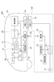
図1は、本発明の一実施形態に係るトルク制御装置を含む車両及び充電装置100を備えた非接触充電システムのブロック図である。なお、本例のトルク制御装置は電気自動車に搭載されるが、ハイブリッド車両等の車両でもよい。
<< First Embodiment >>
FIG. 1 is a block diagram of a contactless charging system including a vehicle including a torque control device and a
図1に示すように、本例の非接触充電システムは、車両側のユニットである車両200と、地上側ユニットである充電装置100とを備え、給電スタンドなどに設置される充電装置100から、非接触で電力を供給し、車両200に設けられるバッテリ21を充電するシステムである。
As shown in FIG. 1, the non-contact charging system of the present example includes a
充電装置100は、交流電源11と、コンバータ12と、充電制御部13と、位置検出部14と、通信部15と、送電コイル16とを備えている。充電装置100は、車両200を駐車する駐車スペースに設けられており、車両200が所定の駐車位置に駐車されるとコイル間の非接触給電により電力を供給する地上側のユニットである。
The
コンバータ12は、交流電源11から送電される交流電力を、高周波の交流電力に変換し、送電コイル16に送電するための電力変換装置である。通信部15は、車両200側の通信部25との間で、無線により通信を行い、情報の送受信を行う。通信部15は、例えば、充電装置100からの電力供給を開始する旨の信号を通信部25に送信したり、あるいは、車両200側から充電装置100から電力を受給したい旨の信号を通信部25から受信したりする。位置検出部14は、充電装置100に設けられる送電コイル16の設置位置に対して、所定の駐車位置に駐車しようとする車両200の受電コイル26の位置を周期的に検出する。位置検出部14は、例えば、赤外線信号又は超音波信号等の信号を発信し、当該信号の変化から位置を検出する。
The
充電制御部13は、コンバータ12、位置検出部14及び通信部15を制御することで、充電装置100を制御する。充電制御部13は、コンバータ12を制御して、送電コイル16から受電コイル26に出力される電力等を制御する。充電制御部13は、充電に関する制御信号を、通信部15から通信部25に送信し、位置検出部14を制御して、送電コイル16に対する受電コイル26の相対的な位置を検出する。
The
送電コイル16は、本例の非接触充電システムを有する駐車スペースに設けられる。非接触充電システムのうち車両200側ユニットを備えた車両200が所定の駐車位置に駐車されると、送電コイル16は、受電コイル26の下部であり、受電コイル26と距離を保って、位置づけられる。送電コイル16は、駐車スペースの表面と平行な円形形状のコイルである。
The
車両200は、バッテリ21と、コンバータ22と、充電制御部23と、整流回路24と、通信部25と、受電コイル26と、インバータ27と、モータ28と、EVコントローラ30とを備えている。受電コイル26は、車両200の底面(シャシ)等で、後方の車輪の間に設けられる。そして当該車両200が、所定の駐車位置に駐車されると、受電コイル26は、送電コイル16の上部であり、送電コイル16と距離を保って、位置づけられる。受電コイル26は、駐車スペースの表面と平行な円形形状のコイルである。整流回路24は受電コイル26により受電された交流電力を直流電力に整流する。コンバータ22は、整流回路24で整流された直流電力を、バッテリ21の充電に適した直流電力に変換するDC−DCコンバータである。またコンバータ22には、バッテリ21と、充電回路となるコンバータ22、整流回路24及び受電コイル26とを切り離すためのスイッチを有するジャンクションボックス(図示しない)が含まれており、当該ジャンクションボックスは、充電制御部23により制御される。
The
バッテリ21は、複数の二次電池を接続することで構成され、車両200の電力源となる。インバータ27は、EVコントローラ30によるスイッチング制御及び運転手のアクセル操作に基づくトルク指令値により、バッテリ21から出力される直流電力を交流電力にし、モータ28に供給する制御回路である。モータ28は、例えば三相の交流電動機により構成され、車両200を駆動させるための駆動源となる。
The
通信部25は、地上側の通信部15と、無線により通信を行い、情報の送受信を行う。充電制御部23は、充電時に、バッテリ21、コンバータ22、整流回路24、通信部25を制御する。また充電制御部23は、EVコントローラ30とCAN通信網で接続され、制御信号の送受信を行う。また充電制御部23は、通信部15及び通信部25を介して、充電制御部13と充電に関する制御信号の送受信を行い、本例の非接触充電システムを制御する。充電制御部23は、充電する際には、コンバータ22に含まれるジャンクションボックスを制御し、受電コイル26から整流回路24、コンバータ22を通りバッテリ21まで導通させて、送電コイル16から送電される電力をバッテリ21に供給することで、バッテリ21を充電する。EVコントローラ30は、車両200全体を制御する制御部であり、車両200を駆動させるためにトルクを設定したり、充電を開始するための信号を充電制御部23に送信したりする。
The
次に、図2A及び図2Bを用いて、送電コイル16の位置と受電コイル26の位置との位置ずれと、本例の非接触充電システムにおける給電効率との関係について説明する。図2A及び図2Bは、送電コイル16及び受電コイル26が対向した状態を示す平面図a)と、斜視図b),c)である。図2A及び図2Bにおいて、X軸及びY軸は、送電コイル16及び受電コイル26の平面方向を示し、Z軸は高さ方向を示す。
Next, using FIG. 2A and FIG. 2B, the relationship between the positional deviation between the position of the
本例の非接触充電システムでは、送電コイル16と受電コイル26との間で、電磁誘導作用により非接触状態で高周波電力の送電及び受電を行う。言い換えると、送電コイル16に電圧が加わると、送電コイル16と受電コイル26との間には磁気的な結合が生じ、送電コイル16から受電コイル26へ電力が供給される。このような非接触充電において、送電コイル16から受電コイル26へ給電される効率(給電効率)は、送電コイル16と受電コイル26との間の結合係数に依存する。
In the non-contact charging system of this example, high-frequency power is transmitted and received between the
いま、図2Aに示すように、平面方向であるX軸、Y軸方向において、受電コイル26が送電コイル16に合致するように車両200が駐車スペースに駐車された場合には、受電コイル26と受電コイル26との相対的な位置は、平面方向において同位置になり、受電コイル26から送電コイル16ための距離は最も短くなる。かかる場合には、受電コイル26と送電コイル16との間の距離が短く、結合係数が最も高くなるため、給電効率は高くなる。
Now, as shown in FIG. 2A, when the
一方、運転者の技量により、図2Bに示すように、送電コイル16と受電コイル26との相対的な位置が、平面方向において、ずれた状態で、車両200が駐車されることがある。図2Bに示す例では、送電コイル16の位置に対する受電コイル26の位置は、X軸方向にXL分、Y軸方向にYL分ずれており、平面方向における送電コイル16と受電コイル26との距離はLとなる。かかる場合には、受電コイル26の位置は、送電コイル16の位置に対して、距離L分、ずれているため、結合係数が図2Aの結合係数と比べて小さくなり、給電効率が低くなる。
On the other hand, depending on the skill of the driver, as shown in FIG. 2B, the
すなわち、本例の非接触充電システムにおいて、車両200を駐車させる際に、受電コイル26と送電コイル16との位置ズレを小さくすることは、給電効率の面で重要であるため、以下に詳述するように、車両200を駐車する際に、受電コイル26と送電コイル16との位置あわせを容易にするトルク制御装置が車両200に搭載されている。
That is, in the contactless charging system of the present example, when parking the
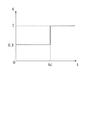
次に、図3〜図5を用いて、本例のトルク制御装置を説明する。図3は本例のトルク制御装置のブロック図であり、図4はトルクマップ31であり、車速(Vsp)に対するトルク(T)の特性である。図5は、受電コイル26と送電コイル16との間の距離(L)に対する補正係数(K)の特性を示す。
Next, the torque control device of this example will be described with reference to FIGS. FIG. 3 is a block diagram of the torque control device of this example, and FIG. 4 is a
図3に示すように、トルク制御装置は、トルクマップ31と、トルク補正部32と、アクセル開度センサ33と、車速センサ34と、バッテリ21と、インバータ27と、モータ28とを備えている。アクセル開度センサ33は、運転手により操作させるアクセルの開度(AP)を検出するためのセンサである。車速センサ34は、車両200の走行速度(Vsp)を検出するためのセンサである。
As shown in FIG. 3, the torque control device includes a
トルクマップ31及びトルク補正部32は、EVコントローラ30の一部であり、アクセル開度(AP)及び車速(Vsp)に基づいて、インバータ27へのトルク指令値(T*)を設定する。トルクマップ31には、図4に示すような、アクセル開度(AP)及び車速(Vsp)と、トルク(T)との対応関係がマップとして予め格納されている。EVコントローラ30は、アクセル開度センサ33により検出されたアクセル開度(AP)及び車速センサ34に検出された車速(Vsp)と、当該マップとを参照して、トルク(T)を設定する。なお、図4において、アクセル開度(AP)が最も小さい時のトルク特性が、クリープのトルク特性を示す。
The
トルク補正部32は、送電コイル16と受電コイル26との相対的な位置に応じて、トルク(T)を補正する。送電コイル16と受電コイル26との相対的な位置は、位置検出部14により検出された受電コイル26の位置情報を、通信部15及び通信部25を介して、EVコントローラ30に送信することで、車両200側で検出される。トルクの補正係数(A)は予め設定されている係数であり、図5に示すように、受電コイル26と送電コイル16との、平面方向における距離(L)に応じて定められている。受電コイル26と送電コイル16との距離(L)が、予め設定されている距離(Lc)より長い場合には、補正係数(K)は1.0に設定され、受電コイル26と送電コイル16との距離(L)が、予め設定されている距離(Lc)以下である場合には、補正係数(K)は0.3に設定されている。そして、トルク補正部32は、EVコントローラ30は、補正係数(K)をトルク(T)に乗ずることで、トルク(T)を補正する。すなわちトルク補正部32は、受電コイル26と送電コイル16との距離(L)が距離(Lc)より長い場合には、トルク(T)を補正せず、受電コイル26と送電コイル16との距離(L)が距離(Lc)以下である場合には、補正する。そして、EVコントローラ30は、トルク補正部32からの出力トルクを、トルク指令値(T*)として、インバータ27に入力する。インバータ27は、EVコントローラ30から入力されたトルク指令値と一致するように、モータ28を制御する。
The
次に、図1及び図3〜図5を用いて、本例のトルク制御装置の制御内容を説明する。まず車両200が、本例の非接触充電システムにより充電するために、所定の駐車位置に近づくと、EVコントローラ30は通信部25を制御し、充電装置100に対して、充電のために駐車する旨の信号を送信する。通信部15により当該信号が受信されると、充電制御部13は、充電のために車両200が所定の駐車位置に近づいていることを認識し、位置検出部14を起動させて、受電コイル26の位置を周期的に検出する。充電制御部23は、位置検出部14により検出された受電コイル26の位置情報を、通信部15により車両200側に送信する。
Next, the control content of the torque control device of this example will be described with reference to FIGS. 1 and 3 to 5. First, when the
EVコントローラ30は、通信部15から送信される受電コイル26の位置情報から、送電コイル16の設置位置に対する受電コイル26の相対的な位置を検出する。位置情報は、周期的に送信されるため、EVコントローラ30は、車両200の駆動中、受電コイル26と送電コイル16とがどの程度近づいているか、認識することができる。そして、EVコントローラ30は、受電コイル26の位置情報から、平面方向における、受電コイル26と送電コイル16との距離(L)を算出する。
The
車両200駆動中、EVコントローラ30は、車速及びアクセル開度から、トルクマップ31のマップを参照し、トルク(T)を設定する。距離(L)が距離(Lc)より大きい場合には、受電コイル26の位置は送電コイル16の位置から離れた位置にあるため、トルク補正部32はトルク(T)を補正せず、当該トルク(T)をトルク指令値(T*)とする。車両200が所定の駐車位置に、さらに近づき、距離(L)が距離(Ls)以下になった場合には、EVコントローラ30は、受電コイル26の位置が送電コイル16の位置に近づいたと判定し、トルク補正部32により、トルク(T)を補正し、補正前のトルクと比べて、小さいトルクをトルク指令値(T*)にする。
During driving of the
すなわち、距離(L)が距離(Ls)より長い場合と、距離(L)が距離(Ls)以下である場合とで、アクセル開度(AP)が同じとすると、モータ28の駆動トルクは、距離(L)が距離(Ls)以下である場合の方が小さくなる。これにより、受電コイル26が送電コイル16に接近し、距離(L)が距離(Ls)以下になると、アクセルの踏み込み量に対する車両200の駆動トルクが小さくなるため、車両200の操作性を高めることができ、受電コイル26に対する送電コイル16の位置合わせを容易に行うことができる。また、言い換えると、本例は、受電コイル26が送電コイル16に接近し、距離(L)が距離(Ls)以下になると、アクセルの踏み込み量に対してアクセルゲインが小さくなり、アクセルの応答性を鈍くするため、車両200の操作性を高めることができ、受電コイル26に対する送電コイル16の位置あわせを容易に行うことができる。
That is, if the accelerator opening (AP) is the same between the case where the distance (L) is longer than the distance (Ls) and the case where the distance (L) is equal to or less than the distance (Ls), the driving torque of the
また、クリープを利用して車両200を所定の駐車位置に駐車している場合には、モータ28の駆動トルクは、距離(L)が距離(Ls)以下になると、距離(L)が距離(Ls)より長い場合のクリープのトルクより小さいトルクをトルク指令値(T*)にする。これにより、受電コイル26が送電コイル16に接近し、距離(L)が距離(Ls)以下になると、クリープ時のトルクに対する車両200の駆動トルクが小さくなるため、車両200の操作性を高めることができ、受電コイル26に対する送電コイル16の位置あわせを容易に行うことができる。
Further, when the
次に、図6を用いて、本例のトルク制御装置の制御手順を説明する。図6は、本例のトルク制御装置の制御手順を示すフローチャートである。なお、図6に示すステップは、所定の周期で繰り返し行われる。 Next, the control procedure of the torque control device of this example will be described with reference to FIG. FIG. 6 is a flowchart showing a control procedure of the torque control device of this example. Note that the steps shown in FIG. 6 are repeatedly performed at a predetermined cycle.
ステップS1にて、EVコントローラ30は、アクセル開度センサ33によりアクセル開度(AP)を検出し、車速センサ34により車速(Vsp)を検出する。ステップS2にて、EVコントローラ30は、検出されたアクセル開度(AP)及び車速(Vsp)から、トルクマップ31に格納されているマップを参照し、トルク(T)を設定する。
In step S1, the
ステップS3にて、EVコントローラ30は、本例の非接触充電システムを搭載した駐車スペースに車両200が近づいているか否かを判定する。当該判定は、車両200に搭載されたGPS機能にから車両200の位置情報と当該駐車スペースの位置情報から判定してもよく、あるいは、乗員による、当該駐車スペースに近づいて車両200を駐車する旨の操作に基づいて判定しよい。そして、車両200が当該駐車スペースに接近していると判定された場合には、EVコントローラ30は、通信部25から、車両200が駐車スペースに近づいていることを示す信号を充電装置100に送信し、充電制御部13は当該信号を通信部15により受信し、位置検出部14により受電コイル26の位置を検出し、通信部15から車両200に、受電コイル26の位置情報を送信する。そして、EVコントローラ30は、通信部25により、当該位置情報を含む信号を受信し、送電コイル16と受電コイル26との相対的な位置を検出する(ステップS4)。
In step S3, the
ステップS5にて、EVコントローラ30は、送電コイル16と受電コイル26との相対的な位置から送電コイル16と受電コイル26との距離(L)を算出し、当該距離(L)と予め設定されている距離(Lc)とを比較する。距離(L)が距離(Lc)以下である場合には、EVコントローラ30は、ステップS2により設定されたトルク(T)を補正する。具体的には、EVコントローラ30は、当該トルク(T)に、図5に示すような、距離(L)に応じて設定されている補正係数(K=0.3)を乗じることで、トルク(T)を補正する。そして、ステップS7にて、EVコントローラ30はステップS6にて補正されたトルクを、トルク指令値(T*)として、インバータ27に入力し、モータ28を制御し、車両200を駆動させる。
In step S5, the
ステップS3に戻り、車両200が当該駐車スペースに接近していないと判定された場合には、EVコントローラ30は、ステップS4〜ステップS6のようなコイルの位置検出やトルク補正を行わずに、ステップS7に遷移する。そして、ステップS7にて、EVコントローラ30はステップS2にて設定されたトルクを、トルク指令値(T*)として、インバータ27に入力し、モータ28を制御し、車両200を駆動させる。
Returning to step S3, if it is determined that the
ステップS5に戻り、距離(L)が距離(Lc)より大きい場合には、ステップS6のようなトルク補正を行わずに、ステップS7に遷移する。そして、ステップS7にて、EVコントローラ30はステップS2にて設定されたトルクを、トルク指令値(T*)として、インバータ27に入力し、モータ28を制御し、車両200を駆動させる。
Returning to step S5, if the distance (L) is greater than the distance (Lc), the process proceeds to step S7 without performing torque correction as in step S6. In step S7, the
上記のように、本例は、送電コイル16の位置と受電コイル26の位置との相対的な位置に応じて、アクセル開度に応じて設定されるトルク(T)を補正し、補正したトルクにより車両200を駆動させる。これにより、受電コイル26の位置と送電コイル16の位置が近づくと、運転者が駐車し易いようにアクセル開度に対するトルクが補正されるため、送電コイル16と受電コイル26との位置あわせを容易にすることができる。
As described above, in this example, the torque (T) set according to the accelerator opening is corrected according to the relative position between the position of the
また本例は、送電コイル16と受電コイル26との距離(L)が所定の距離(Ls)より短くなった場合に、アクセル開度に応じて設定されるトルク(T)を補正し、補正したトルクにより車両200を駆動させる。これにより、受電コイル26の位置と送電コイル16の位置が近づくと、アクセルの応答性が鈍くなるように、トルクが補正されるため、送電コイル16と受電コイル26との位置ずれが小さくなるように、駐車位置の精度が高まり、送電コイル16と受電コイル26との位置あわせを容易にすることができる。
Further, in this example, when the distance (L) between the
また本例の非接触充電システムにおいて、車両駆動中には、地上側で、送電コイル16と受電コイル26との相対的な位置を検出し、検出された位置を含む信号を車両200側に送信し、車両200側で、当該信号に含まれる当該相対的な位置に応じてトルクを補正して車両200を駆動させ、車両200停車後には、地上側の送電コイル16から電力を非接触で供給し、車両200側の受電コイル26により電力を受電し、車両200に搭載されたバッテリ21を充電する。これにより、受電コイル26の位置と送電コイル16の位置が近づくと、運転者が駐車し易いようにアクセル開度に対するトルクが補正されるため、送電コイル16と受電コイル26との位置あわせを容易にすることができる。また駐車後の充電において、送電コイル16と受電コイル26との位置ズレが小さいため、給電効率を高めることができ、充電時間の短縮化を図ることができる。
In the non-contact charging system of this example, the relative position between the
なお位置検出部14は、車両200の受電コイル26を撮像し、撮像画像を解析することで、送電コイル16に対する受電コイル26の相対的な位置を検出してもよい。また位置検出部14は、地上側又は車両200側のいずれか一方に電波を送信する送信用アンテナを設け、地上側又は車両200側のいずれか他方に電波を受信する受信用アンテナを設け、これらアンテナ間における電波の送受信信号から、送電コイル16と受電コイル26との相対的な位置を検出してもよい。また位置検出部14は、GPSシステムから車両200の位置情報を入手することで、送電コイル16と受電コイル26との相対的な位置を検出してもよい。また、位置検出部14は、車両200に設けてもよい。
The
また本例のトルク制御装置によるトルク補正は、車両200前進時のトルク補正に限らず、車両200後退時のトルク補正も含まれる。
Further, torque correction by the torque control device of this example is not limited to torque correction when the
また本例は、送電コイル16と受電コイル26との位置ズレを小さくするために、位置検出部14により、送電コイル16に対する受電コイル26の相対位置を検出するが、所定の駐車位置に対する車両200の位置の相対的な位置を検出してもよい。すなわち、上記の送電コイル16の位置が当該所定の駐車位置に対応し、上記の受電コイル26の位置が当該車両200の位置に対応する。
Further, in this example, in order to reduce the positional deviation between the
また本例のトルク制御装置は、非接触充電システムを備えた車両200に限らず、車両200の駐車支援システムを備えた車両200に搭載してもよい。この際には、位置検出部14は、所定の駐車位置と車両200の位置との相対的な位置を検出し、EVコントローラ30は、検出された当該相対的な位置に応じて、トルクを補正すればよい。
Further, the torque control device of this example is not limited to the
また位置検出部14は車両側に設け、送電コイル16の位置を検出することで、送電コイル16と受電コイル26との相対的な位置を検出してもよい。
Further, the
また本例のトルク制御装置は、車両を駐車させる際にモータ28の駆動トルクを補正するが、エンジンを駆動させて車両を駐車する場合に、エンジンのトルクを上記と同様に補正してもよい。
The torque control device of this example corrects the driving torque of the
上記のEVコントローラ30のうちトルクマップ31を含む制御部が本発明の「トルク設定手段」に相当し、EVコントローラ30のうちトルクマップ31を含む制御部及びインバータ27が本発明の「トルク制御手段」に相当し、交流電源11、コンバータ12及び充電制御部13が「充電器」に相当し、位置検出部14が「位置検出手段」に相当する。
The control unit including the
《第2実施形態》
図7は、発明の他の実施形態に係るトルク制御装置を含む車両200の駐車スペースの説明図である。本例では、上述した第1実施形態に対して、受電コイル26と送電コイル16との間の距離(L)に対する補正係数(K)の特性が異なる。これ以外の構成は上述した第1実施形態と同じであるため、その記載を援用する。
<< Second Embodiment >>
FIG. 7 is an explanatory diagram of a parking space of a
以下、図7及び図8を用いて、発明の他の実施形態に係るトルク制御装置を説明する。図8は、受電コイル26と送電コイル16との間の距離(L)に対する補正係数(K)の特性を示す。図7に示すように、地上側の充電装置100を設ける駐車スペース300の地上に、送電コイル16が設けられている。本例の車両200は、図7の矢印の方向に進行し、所定の駐車位置に駐車される。ここで、X軸を車両200の車幅方向に、Y軸を車両200の駐車時の進行方向にとり、X軸とY軸との交点を、送電コイル16の中心点とする。またY軸の正負の符号について、送電コイルの中心点に対して、駐車スペース300の入出庫口の方向(図7の上方)に伸びる距離を正の方向とし、送電コイルの中心点に対して、駐車スペース300の入出庫口と逆側の方向(図7の下方)に伸びる距離を負の方向とする。
Hereinafter, a torque control device according to another embodiment of the invention will be described with reference to FIGS. 7 and 8. FIG. 8 shows the characteristic of the correction coefficient (K) with respect to the distance (L) between the
EVコントローラ30は、位置検出部14にから送信される受電コイル26の位置情報から、駐車スペース300の平面方向のうち、車両200の駐車時の進行方向における、受電コイル26と送電コイル16との距離(L)を算出する。そして、EVコントローラ30は、車速及びアクセル開度から、トルクマップ31のマップを参照し、トルク(T)を設定し、トルク補正部32により、補正係数(K)を用いて、設定されたトルク(T)を、距離(L)に応じて補正する。
The
トルク補正部32で設定されている補正係数(K)について、図8に示すように、受電コイル26と送電コイル16との距離(L)が、予め設定されている距離(Y2)より長い場合には、又は、予め設定されている距離(−Y2)より長い場合には、補正係数(K)は1.0に設定される。また、受電コイル26と送電コイル16との距離(L)が予め設定されている距離(Y1)より短い場合には、又は、予め設定されている距離(−Y1)より短い場合には、補正係数(K)は0.3に設定されている。また、受電コイル26と送電コイル16との距離(L)が距離(Y1)以上で距離(Y2)以下である場合には、補正係数(K)は、距離の増加に対して、0.3から1.0の範囲で比例して増加する。受電コイル26と送電コイル16との距離(L)が距離(−Y1)以上で距離(−Y2)以下である場合には、補正係数(K)は、距離の減少に対して、0.3から1.0の範囲で比例して減少する。
For the correction coefficient (K) set by the
これにより、EVコントローラ30は、距離(L)が距離(Y2)より長い場合には、受電コイル26の位置は送電コイル16の位置から離れた位置にあるため、トルク補正部32によりトルク(T)を補正せず、トルク(T)をトルク指令値(T*)とする。車両200が送電コイル16の位置にさらに近づき、距離(L)が距離(Y2)以下になると、EVコントローラ30は、距離(L)が短くなるにつれて、補正係数(K)を小さくして、トルク指令値(T*)を徐々に小さくするように、トルク(T)を補正する。さらに、受電コイル26の位置が送電コイル16の位置に近づき、距離(L)が距離(Y1)以下になると、EVコントローラ30は、補正係数を一定の値(K=0.3)にして、トルク(T)を補正する。
Thereby, when the distance (L) is longer than the distance (Y 2 ), the
また、本例では、受電コイル26が送電コイル16の位置を越えて、車両200が駐車され、受電コイル26の位置を送電コイル16の位置に戻すように車両200を駆動する際にも、上記のようなトルク制御が行われる。すなわち、EVコントローラ30は、距離(L)が距離(−Y2)より大きい場合には、受電コイル26の位置は送電コイル16の位置からかなり離れているため、トルク補正部32によりトルク(T)を補正せず、トルク(T)をトルク指令値(T*)とする。そして、徐々に受電コイル26が送電コイル16に近づき、距離(L)が距離(−Y2)以下になると、EVコントローラ30は、距離(L)が小さくなるにつれて、補正係数(K)を小さくして、トルク指令値(T*)を徐々に小さくするように、トルク(T)を補正する。さらに、受電コイル26の位置が送電コイル16の位置に近づき、距離(L)が距離(−Y1)以下になると、EVコントローラ30は、補正係数を一定の値(K=0.3)にして、トルク(T)を補正する。
Further, in this example, when the
上記のように、本例は、送電コイル16の位置と受電コイル26の位置との、車両200の駐車時の進行方向における距離が所定の距離(Y2又は−Y2)より短くなるほど、トルク(T)が小さくなるように補正する。これにより、受電コイル26の位置と送電コイル16の位置が近づくと、アクセルの応答性が徐々に鈍くなるように、トルクが徐々に補正されるため、送電コイル16と受電コイル26との位置ずれが小さくなり、駐車の位置の精度が高まり、送電コイル16と受電コイル26との位置あわせを容易にすることができる。
As described above, in this example, as the distance between the position of the
なお本例のトルク制御装置は、受電コイル26の位置と送電コイル16の位置との間で、車両200の駐車時の進行方向(図7のY軸方向)の成分を距離(L)として算出し上記のトルク制御を行うが、車両200の車幅方向(図7のX軸方向)の成分を距離(L)として算出し上記のトルク制御を行ってもよい。また、EVコントローラ30は、受電コイル26の位置と送電コイル16の位置との間で、駐車スペースの平面方向における距離を、距離(L)として算出し上記のトルク制御を行ってもよい。さらに、EVコントローラ30は、受電コイル26と送電コイル16との距離(L)を、駐車スペースの平面方向の成分だけでなく、駐車スペースの平面方向に対して垂直方向(図2a及び図2bのZ方向)の成分も含めて、距離(L)とし、上記のトルク制御を行ってもよい。
Note that the torque control device of this example calculates a component in the traveling direction (Y-axis direction in FIG. 7) when the
また本例のトルク制御装置は、送電コイル16と受電コイル26との距離(L)が所定の距離より短くなった時点からの経過時間に伴い、補正係数(K)を徐々に大きくし、トルク(T)が小さくなるよう補正してもよい。車両200を所定の駐車位置に向けて駆動させている場合には、時間の経過と共に受電コイル26と送電コイル16との距離が短くなるため、本例では、閾値として所定の距離を予め設定し、距離(L)が当該所定の距離より短くなった時点からの経過時間に応じて、トルク(T)を補正する。これにより、受電コイル26の位置と送電コイル16の位置が近づくと、アクセルの応答性が鈍くなるように、トルクが補正されるため、送電コイル16と受電コイル26との位置ずれが小さくなるように、駐車の位置の精度が高まり、送電コイル16と受電コイル26との位置あわせを容易にすることができる。
In addition, the torque control device of this example gradually increases the correction coefficient (K) with the elapsed time from the time when the distance (L) between the
100…充電装置
11…交流電源
12…コンバータ
13…充電制御部
14…位置検出部
15…通信部
16…送電コイル
200…車両
21…バッテリ
22…コンバータ
23…充電制御部
24…整流回路
25…通信部
26…受電コイル
27…インバータ(INV)
28…モータ
30…EVコントローラ
31…トルクマップ
32…トルク補正部
33…アクセル開度センサ
34…車速センサ
300…駐車スペース
DESCRIPTION OF
DESCRIPTION OF
Claims (5)
アクセル開度を検出するアクセル開度検出手段と、
前記アクセル開度検出手段により検出されたアクセル開度に基づいて車両を駆動させるトルクを設定するトルク設定手段と、
前記車両の位置が所定の駐車位置に近づくと、アクセルの踏み込み量に対する車両の駆動トルクが相対的に小さくなるように、前記トルク設定手段により設定されたトルクを補正し、補正されたトルクにより車両を駆動させるトルク制御手段とを備え、
前記所定の駐車位置は前記送電コイルの位置に対応し、
前記車両の位置は前記受電コイルの位置に対応する
ことを特徴とするトルク制御装置。 A power receiving coil for receiving power from the power transmitting coil in a contactless manner at least by magnetic coupling;
An accelerator opening detecting means for detecting the accelerator opening;
Torque setting means for setting a torque for driving the vehicle based on the accelerator opening detected by the accelerator opening detecting means;
When the position of the vehicle approaches a predetermined parking position, the torque set by the torque setting means is corrected so that the driving torque of the vehicle with respect to the amount of depression of the accelerator becomes relatively small. Torque control means for driving
The predetermined parking position corresponds to the position of the power transmission coil,
The torque control device, wherein the position of the vehicle corresponds to the position of the power receiving coil .
前記アクセル開度検出手段により検出されたアクセル開度に基づいて車両を駆動させるトルクを設定するトルク設定手段と、
前記車両の位置が所定の駐車位置に近づいて前記車両を駐車する操作に基づいて、アクセルの踏み込み量に対する車両の駆動トルクが相対的に小さくなるように、前記トルク設定手段により設定されたトルクを補正し、補正されたトルクにより車両を駆動させるトルク制御手段とを備える
ことを特徴とするトルク制御装置。 An accelerator opening detecting means for detecting the accelerator opening;
Torque setting means for setting a torque for driving the vehicle based on the accelerator opening detected by the accelerator opening detecting means;
Based on the operation of parking the vehicle when the vehicle position approaches a predetermined parking position, the torque set by the torque setting means is set so that the driving torque of the vehicle relative to the accelerator depression amount becomes relatively small. A torque control device comprising: a torque control unit that corrects and drives the vehicle with the corrected torque.
前記アクセル開度検出手段により検出されたアクセル開度に基づいて車両を駆動させるトルクを設定するトルク設定手段と、
前記車両の位置が所定の駐車位置に近づくと、アクセルの踏み込み量に対する車両の駆動トルクが相対的に小さくなるように、前記トルク設定手段により設定されたトルクを補正し、補正されたトルクにより車両を駆動させるトルク制御手段とを備え、
前記トルク制御手段は、
前記所定の駐車位置と前記車両の位置の距離が所定の距離より短くなるほど、前記トルク設定手段により設定されたトルクが小さくなるよう補正する
ことを特徴とするトルク制御装置。 An accelerator opening detecting means for detecting the accelerator opening;
Torque setting means for setting a torque for driving the vehicle based on the accelerator opening detected by the accelerator opening detecting means;
When the position of the vehicle approaches a predetermined parking position, the torque set by the torque setting means is corrected so that the driving torque of the vehicle with respect to the amount of depression of the accelerator becomes relatively small. Torque control means for driving
The torque control means includes
The torque control device according to claim 1 , wherein the torque set by the torque setting means is corrected to be smaller as the distance between the predetermined parking position and the vehicle position is shorter than a predetermined distance .
ことを特徴とする請求項1〜3のいずれか一項に記載のトルク制御装置。 Torque control device according to any one of claims 1 to 3, further comprising a position detecting means for detecting the relative position between the position of the vehicle and the predetermined parking position.
前記充電装置は、The charging device is:
前記送電コイルへ電力を供給する充電器と、A charger for supplying power to the power transmission coil;
前記送電コイルと前記受電コイルとの相対的な位置とを検出する位置検出手段と、Position detecting means for detecting a relative position between the power transmission coil and the power receiving coil;
前記位置検出手段により検出された位置を含む信号を送信する送信手段とを備え、Transmission means for transmitting a signal including the position detected by the position detection means,
前記車両は、The vehicle is
前記受電コイルにより受電した電力により充電されるバッテリと、A battery charged with power received by the power receiving coil;
アクセル開度を検出するアクセル開度検出手段と、An accelerator opening detecting means for detecting the accelerator opening;
前記アクセル開度検出手段により検出されたアクセル開度に基づいて前記車両を駆動させるトルクを設定するトルク設定手段と、Torque setting means for setting a torque for driving the vehicle based on the accelerator opening detected by the accelerator opening detecting means;
前記送信手段から送信される信号を受信する受信手段と、Receiving means for receiving a signal transmitted from the transmitting means;
前記受信手段により受信された信号から、前記送電コイルの位置と前記受電コイルの位置との相対的な位置を検出し、前記受電コイルの位置が前記送電コイルの位置に近づくと、アクセルの踏み込み量に対する車両の駆動トルクが相対的に小さくなるように、前記トルク設定手段により設定されたトルクを補正し、補正されたトルクにより前記車両を駆動させるトルク制御手段とを備えるWhen the relative position between the position of the power transmission coil and the position of the power reception coil is detected from the signal received by the reception means, and the position of the power reception coil approaches the position of the power transmission coil, the amount of depression of the accelerator Torque control means for correcting the torque set by the torque setting means and driving the vehicle with the corrected torque so that the driving torque of the vehicle with respect to
ことを特徴とする非接触充電システム。A non-contact charging system characterized by that.
Priority Applications (10)
| Application Number | Priority Date | Filing Date | Title |
|---|---|---|---|
| JP2011095331A JP5834463B2 (en) | 2011-04-21 | 2011-04-21 | Torque control device and non-contact charging system |
| US14/112,804 US9623767B2 (en) | 2011-04-21 | 2012-02-08 | Torque control apparatus and contactless charging system |
| EP12774752.5A EP2700530B1 (en) | 2011-04-21 | 2012-02-08 | Torque control apparatus and contactless charging system |
| CN201280019589.9A CN103492219B (en) | 2011-04-21 | 2012-02-08 | Torque control device and non-contact charger systems |
| BR112013027111-6A BR112013027111B1 (en) | 2011-04-21 | 2012-02-08 | TORQUE CONTROL UNIT |
| MYPI2013003770A MY159192A (en) | 2011-04-21 | 2012-02-08 | Torque control apparatus and contactless charging system |
| RU2013151666/11A RU2561887C2 (en) | 2011-04-21 | 2012-02-08 | Torsion torque control device and contactless charging system |
| MX2013012152A MX2013012152A (en) | 2011-04-21 | 2012-02-08 | Torque control apparatus and contactless charging system. |
| KR1020137030498A KR101495470B1 (en) | 2011-04-21 | 2012-02-08 | Torque control apparatus and contactless charging system |
| PCT/JP2012/052803 WO2012144253A1 (en) | 2011-04-21 | 2012-02-08 | Torque control apparatus and contactless charging system |
Applications Claiming Priority (1)
| Application Number | Priority Date | Filing Date | Title |
|---|---|---|---|
| JP2011095331A JP5834463B2 (en) | 2011-04-21 | 2011-04-21 | Torque control device and non-contact charging system |
Publications (2)
| Publication Number | Publication Date |
|---|---|
| JP2012228119A JP2012228119A (en) | 2012-11-15 |
| JP5834463B2 true JP5834463B2 (en) | 2015-12-24 |
Family
ID=47041377
Family Applications (1)
| Application Number | Title | Priority Date | Filing Date |
|---|---|---|---|
| JP2011095331A Active JP5834463B2 (en) | 2011-04-21 | 2011-04-21 | Torque control device and non-contact charging system |
Country Status (10)
| Country | Link |
|---|---|
| US (1) | US9623767B2 (en) |
| EP (1) | EP2700530B1 (en) |
| JP (1) | JP5834463B2 (en) |
| KR (1) | KR101495470B1 (en) |
| CN (1) | CN103492219B (en) |
| BR (1) | BR112013027111B1 (en) |
| MX (1) | MX2013012152A (en) |
| MY (1) | MY159192A (en) |
| RU (1) | RU2561887C2 (en) |
| WO (1) | WO2012144253A1 (en) |
Families Citing this family (38)
| Publication number | Priority date | Publication date | Assignee | Title |
|---|---|---|---|---|
| DE102011109834A1 (en) * | 2011-08-09 | 2013-02-14 | Leopold Kostal Gmbh & Co. Kg | Charging station and method for inductively charging the traction battery of an electrically powered vehicle |
| US9908426B2 (en) * | 2012-09-27 | 2018-03-06 | Tdk Corporation | Vehicle and mobile body system |
| JP6142509B2 (en) * | 2012-11-13 | 2017-06-07 | 株式会社Ihi | Non-contact power feeding device |
| US9540000B2 (en) | 2012-11-27 | 2017-01-10 | Nissan Motor Co., Ltd. | Acceleration suppression device for vehicle, and acceleration suppression method for vehicle |
| JP5900647B2 (en) * | 2012-11-27 | 2016-04-06 | 日産自動車株式会社 | Vehicle acceleration suppression device and vehicle acceleration suppression method |
| WO2014083815A1 (en) * | 2012-11-27 | 2014-06-05 | 日産自動車株式会社 | Vehicle acceleration restriction device and vehicle acceleration restriction method |
| US9399400B2 (en) | 2012-11-27 | 2016-07-26 | Nissan Motor Co., Ltd. | Vehicular acceleration suppression device and vehicular acceleration suppression method |
| JP5900650B2 (en) * | 2012-11-27 | 2016-04-06 | 日産自動車株式会社 | Vehicle acceleration suppression device and vehicle acceleration suppression method |
| JP5900651B2 (en) * | 2012-11-27 | 2016-04-06 | 日産自動車株式会社 | Driving support device and driving support method |
| JP6007991B2 (en) * | 2012-11-27 | 2016-10-19 | 日産自動車株式会社 | Vehicle acceleration suppression device and vehicle acceleration suppression method |
| US9616885B2 (en) | 2012-11-27 | 2017-04-11 | Nissan Motor Co., Ltd. | Vehicular acceleration suppression device |
| WO2014083829A1 (en) * | 2012-11-27 | 2014-06-05 | 日産自動車株式会社 | Acceleration restriction device for vehicle and acceleration restriction method for vehicle |
| JP5991382B2 (en) * | 2012-11-27 | 2016-09-14 | 日産自動車株式会社 | Vehicle acceleration suppression device and vehicle acceleration suppression method |
| JP5892260B2 (en) * | 2012-11-27 | 2016-03-23 | 日産自動車株式会社 | Vehicle acceleration suppression device and vehicle acceleration suppression method |
| JP2014110681A (en) * | 2012-12-03 | 2014-06-12 | Nissan Motor Co Ltd | Non-contact power supply device, non-contact power supply system, and non-contact power supply method |
| WO2014157090A1 (en) * | 2013-03-29 | 2014-10-02 | 日産自動車株式会社 | Contactless electricity supply system and vehicle |
| JP5857999B2 (en) * | 2013-04-26 | 2016-02-10 | トヨタ自動車株式会社 | Power receiving device, parking assist device, and power transmission system |
| US9931954B2 (en) * | 2014-02-04 | 2018-04-03 | Ford Global Technologies, Llc | Vertical wireless power transfer system for charging electric vehicles |
| JP6196924B2 (en) * | 2014-03-21 | 2017-09-13 | Ihi運搬機械株式会社 | Contactless power supply system |
| CN104113125A (en) * | 2014-08-12 | 2014-10-22 | 山东齐星铁塔科技股份有限公司 | Wireless charging unit of mechanical stereo garage |
| JP5953385B1 (en) * | 2015-02-25 | 2016-07-20 | 本田技研工業株式会社 | vehicle |
| JP6060195B2 (en) | 2015-03-06 | 2017-01-11 | 本田技研工業株式会社 | Vehicle parking control device |
| JP6309162B2 (en) * | 2015-03-16 | 2018-04-11 | 三菱電機エンジニアリング株式会社 | Wireless power supply system and moving body |
| KR102492190B1 (en) | 2016-01-11 | 2023-01-27 | 삼성전자주식회사 | Wireless power transmission device, a wireless charging system and method of controlling thereof |
| DE102016202460A1 (en) | 2016-02-17 | 2017-08-17 | Bayerische Motoren Werke Aktiengesellschaft | Assistance to the driver of a motor vehicle when positioning the motor vehicle at a predetermined target position |
| CN106004491A (en) * | 2016-06-02 | 2016-10-12 | 深圳大学 | Vehicle wireless charging alignment method and system |
| DE102016221471A1 (en) * | 2016-11-02 | 2018-05-03 | Bayerische Motoren Werke Aktiengesellschaft | Method for providing correction data for a position determination |
| CN108146256A (en) * | 2016-12-06 | 2018-06-12 | 比亚迪股份有限公司 | Electric vehicle and its wireless charging automatic contraposition device and method |
| DE102016224804A1 (en) * | 2016-12-13 | 2018-06-14 | Bayerische Motoren Werke Aktiengesellschaft | Method for determining the position of a charging station for the wireless transmission of electrical energy to a vehicle |
| DE102017130169A1 (en) * | 2017-02-24 | 2018-08-30 | Denso Ten Limited | CHARGING DEVICE SUPPORT |
| JP6994340B2 (en) * | 2017-10-02 | 2022-01-14 | 株式会社Subaru | vehicle |
| JP7057664B2 (en) * | 2017-12-28 | 2022-04-20 | 株式会社Subaru | Non-contact charging device |
| KR101857407B1 (en) * | 2018-01-30 | 2018-06-20 | (주)에프티글로벌 | A wireless power transfer system of identifying a position of the automated guided vehicle and method for identifying a position of the automated Guided Vehicle |
| RU195212U1 (en) * | 2019-10-21 | 2020-01-17 | Акционерное общество "Научно-производственная корпорация "Космические системы мониторинга, информационно-управляющие и электромеханические комплексы" им. А.Г. Иосифьяна | SPACECRAFT BATTERY |
| JP7386071B2 (en) * | 2019-12-20 | 2023-11-24 | 株式会社Subaru | Vehicle control equipment and vehicles |
| JP7015338B2 (en) * | 2020-03-16 | 2022-02-02 | 本田技研工業株式会社 | Parking support device |
| JP7510604B2 (en) * | 2020-07-01 | 2024-07-04 | マツダ株式会社 | Electric vehicle powertrain system |
| JP7348979B1 (en) | 2022-03-22 | 2023-09-21 | ソフトバンク株式会社 | Communication device, program, and control method |
Family Cites Families (30)
| Publication number | Priority date | Publication date | Assignee | Title |
|---|---|---|---|---|
| EP0788212B1 (en) * | 1996-01-30 | 2002-04-17 | Sumitomo Wiring Systems, Ltd. | Connection system and connection method for an electric automotive vehicle |
| EP0788211B1 (en) | 1996-01-30 | 2002-08-28 | Sumitomo Wiring Systems, Ltd. | A connection system and a connection method |
| JP3586955B2 (en) * | 1996-02-02 | 2004-11-10 | 住友電装株式会社 | Electric vehicle charging system |
| JPH09242579A (en) * | 1996-03-06 | 1997-09-16 | Toyota Motor Corp | Prime mover control device |
| JPH10272913A (en) * | 1997-01-29 | 1998-10-13 | Toyota Motor Corp | Vehicular control device |
| JP2000136738A (en) * | 1998-10-30 | 2000-05-16 | Toyota Motor Corp | Parking operation supporting device for vehicle |
| US6411882B1 (en) * | 2000-12-02 | 2002-06-25 | Ford Global Technologies, Inc. | Drive-by-wire vehicle engine output control system |
| DE10256770A1 (en) * | 2002-12-05 | 2004-06-17 | Bayerische Motoren Werke Ag | Method for steering a vehicle to be parked backwards into a parking space |
| JP2005057962A (en) * | 2003-08-07 | 2005-03-03 | Nissan Motor Co Ltd | Motor control device |
| JP2005178626A (en) * | 2003-12-19 | 2005-07-07 | Toyota Motor Corp | Vehicular integrated control system |
| US20070131505A1 (en) * | 2005-07-16 | 2007-06-14 | Kim Bryan H J | Magnetic Induction Charging System for Vehicles |
| JP4414959B2 (en) * | 2005-11-16 | 2010-02-17 | アイシン精機株式会社 | Parking assistance device |
| US8352146B2 (en) * | 2006-11-13 | 2013-01-08 | Ford Global Technologies, Llc | Engine response adjustment based on traffic conditions |
| US8538631B2 (en) * | 2007-01-23 | 2013-09-17 | GM Global Technology Operations LLC | Method and system for vehicle parking assistance |
| JP5105149B2 (en) * | 2007-04-18 | 2012-12-19 | アイシン精機株式会社 | Parking assistance device |
| JP4772744B2 (en) * | 2007-05-17 | 2011-09-14 | 昭和飛行機工業株式会社 | Signal transmission coil communication device for non-contact power feeding device |
| US20110050164A1 (en) * | 2008-05-07 | 2011-03-03 | Afshin Partovi | System and methods for inductive charging, and improvements and uses thereof |
| EP2347928B8 (en) * | 2008-11-07 | 2020-02-26 | Toyota Jidosha Kabushiki Kaisha | Power feeding system for vehicle, and electrically powered vehicle |
| JP2010144667A (en) * | 2008-12-19 | 2010-07-01 | Kenwood Corp | Safe driving device of vehicle |
| CN101764435B (en) * | 2008-12-22 | 2014-09-10 | 爱信艾达株式会社 | Power reception guidance device |
| JP2010183813A (en) * | 2009-02-09 | 2010-08-19 | Toyota Industries Corp | Resonance type non-contact charging system |
| US9873347B2 (en) * | 2009-03-12 | 2018-01-23 | Wendell Brown | Method and apparatus for automatic charging of an electrically powered vehicle |
| JP2010246348A (en) * | 2009-04-09 | 2010-10-28 | Fujitsu Ten Ltd | Power-receiving device and power-transmitting device |
| JP5418961B2 (en) * | 2009-04-09 | 2014-02-19 | 富士電機株式会社 | Induction motor control device |
| JP2011035953A (en) * | 2009-07-29 | 2011-02-17 | Denso Corp | Vehicle charging device and system |
| KR20110042403A (en) * | 2009-10-19 | 2011-04-27 | 김현민 | Wireless charging system for electric car and charging method therefor |
| US10343535B2 (en) * | 2010-04-08 | 2019-07-09 | Witricity Corporation | Wireless power antenna alignment adjustment system for vehicles |
| US8532900B2 (en) * | 2010-09-21 | 2013-09-10 | Honda Motor Co., Ltd. | Accelerator pedal device for vehicle and pedal reaction force control method |
| US8513915B2 (en) * | 2010-10-21 | 2013-08-20 | GM Global Technology Operations LLC | Vehicle alignment for inductive charging |
| US8483899B2 (en) * | 2011-10-06 | 2013-07-09 | Ford Global Technologies, Llc | Vehicle guidance system |
-
2011
- 2011-04-21 JP JP2011095331A patent/JP5834463B2/en active Active
-
2012
- 2012-02-08 WO PCT/JP2012/052803 patent/WO2012144253A1/en active Application Filing
- 2012-02-08 KR KR1020137030498A patent/KR101495470B1/en active IP Right Grant
- 2012-02-08 MX MX2013012152A patent/MX2013012152A/en active IP Right Grant
- 2012-02-08 BR BR112013027111-6A patent/BR112013027111B1/en active IP Right Grant
- 2012-02-08 EP EP12774752.5A patent/EP2700530B1/en active Active
- 2012-02-08 RU RU2013151666/11A patent/RU2561887C2/en active
- 2012-02-08 MY MYPI2013003770A patent/MY159192A/en unknown
- 2012-02-08 US US14/112,804 patent/US9623767B2/en active Active
- 2012-02-08 CN CN201280019589.9A patent/CN103492219B/en active Active
Also Published As
| Publication number | Publication date |
|---|---|
| BR112013027111B1 (en) | 2020-05-26 |
| RU2013151666A (en) | 2015-05-27 |
| MY159192A (en) | 2016-12-30 |
| RU2561887C2 (en) | 2015-09-10 |
| KR20130141703A (en) | 2013-12-26 |
| EP2700530A1 (en) | 2014-02-26 |
| CN103492219B (en) | 2016-12-28 |
| KR101495470B1 (en) | 2015-03-02 |
| EP2700530B1 (en) | 2018-05-02 |
| JP2012228119A (en) | 2012-11-15 |
| MX2013012152A (en) | 2013-12-06 |
| CN103492219A (en) | 2014-01-01 |
| EP2700530A4 (en) | 2016-01-27 |
| US20140039728A1 (en) | 2014-02-06 |
| WO2012144253A1 (en) | 2012-10-26 |
| US9623767B2 (en) | 2017-04-18 |
Similar Documents
| Publication | Publication Date | Title |
|---|---|---|
| JP5834463B2 (en) | Torque control device and non-contact charging system | |
| JP6427873B2 (en) | Parking assistance device and system | |
| JP5418583B2 (en) | Vehicle and vehicle parking assist device | |
| JP4849190B2 (en) | Vehicle power supply system and electric vehicle | |
| JP5719466B2 (en) | Contactless charging system | |
| JP6217388B2 (en) | Power receiving device and vehicle including the same | |
| US20140103871A1 (en) | Contactless electricity supply device | |
| US20210143684A1 (en) | Contactless power feeding apparatus and contactless power feeding system | |
| JP2011160515A (en) | Radio charging apparatus for vehicle | |
| WO2012132946A1 (en) | Parking facility | |
| JP5557618B2 (en) | Vehicle charging system | |
| WO2014184864A1 (en) | Contactless power transmission device and moving vehicle | |
| WO2016068135A1 (en) | Power transmission device, power transmission method, and non-contact power supply system | |
| CN108928247B (en) | Contactless electrical power transmission system | |
| WO2012090341A1 (en) | Power control device for contactless charging device | |
| WO2015076290A1 (en) | Non-contact electric power transmission and reception system | |
| JP5966332B2 (en) | Mobile vehicle and non-contact power transmission device | |
| JP2013153564A (en) | Moving vehicle power feeding system | |
| JP2013005539A (en) | Non-contact power supply system | |
| JP2016103938A (en) | Vehicle power supply equipment | |
| JP2013132141A (en) | Power transmission system | |
| JP2014110681A (en) | Non-contact power supply device, non-contact power supply system, and non-contact power supply method | |
| JP5974460B2 (en) | Mobile vehicle and non-contact power transmission device | |
| JP6428420B2 (en) | Contactless power supply system |
Legal Events
| Date | Code | Title | Description |
|---|---|---|---|
| A621 | Written request for application examination |
Free format text: JAPANESE INTERMEDIATE CODE: A621 Effective date: 20140225 |
|
| A131 | Notification of reasons for refusal |
Free format text: JAPANESE INTERMEDIATE CODE: A131 Effective date: 20141125 |
|
| A521 | Request for written amendment filed |
Free format text: JAPANESE INTERMEDIATE CODE: A523 Effective date: 20150120 |
|
| A131 | Notification of reasons for refusal |
Free format text: JAPANESE INTERMEDIATE CODE: A131 Effective date: 20150407 |
|
| A521 | Request for written amendment filed |
Free format text: JAPANESE INTERMEDIATE CODE: A523 Effective date: 20150605 |
|
| TRDD | Decision of grant or rejection written | ||
| A01 | Written decision to grant a patent or to grant a registration (utility model) |
Free format text: JAPANESE INTERMEDIATE CODE: A01 Effective date: 20151006 |
|
| A61 | First payment of annual fees (during grant procedure) |
Free format text: JAPANESE INTERMEDIATE CODE: A61 Effective date: 20151019 |
|
| R151 | Written notification of patent or utility model registration |
Ref document number: 5834463 Country of ref document: JP Free format text: JAPANESE INTERMEDIATE CODE: R151 |