JP5825840B2 - Inkjet recording apparatus and inkjet recording method - Google Patents
Inkjet recording apparatus and inkjet recording method Download PDFInfo
- Publication number
- JP5825840B2 JP5825840B2 JP2011109261A JP2011109261A JP5825840B2 JP 5825840 B2 JP5825840 B2 JP 5825840B2 JP 2011109261 A JP2011109261 A JP 2011109261A JP 2011109261 A JP2011109261 A JP 2011109261A JP 5825840 B2 JP5825840 B2 JP 5825840B2
- Authority
- JP
- Japan
- Prior art keywords
- recording
- ejection port
- ink
- group
- ratio
- Prior art date
- Legal status (The legal status is an assumption and is not a legal conclusion. Google has not performed a legal analysis and makes no representation as to the accuracy of the status listed.)
- Expired - Fee Related
Links
Images


Landscapes
- Ink Jet (AREA)
- Particle Formation And Scattering Control In Inkjet Printers (AREA)
Description
本発明は、記録媒体に対して記録ヘッドからインクを吐出させて記録を行うインクジェット記録装置、インクジェット記録方法、およびプログラムに関するものである。 The present invention relates to an ink jet recording apparatus, an ink jet recording method, and a program that perform recording by ejecting ink from a recording head onto a recording medium.
記録ヘッドの主走査方向の往復移動を伴って画像を記録するシリアルスキャン方式のインクジェット記録装置において、記録ヘッドには、主走査方向と交差する方向に沿って、インクを吐出可能な複数のノズルが配列されている。このようなノズル列が主走査方向に並ぶように複数配置された記録ヘッドにおいては、記録ヘッドの走査方向の前側に位置するノズル列から順にインクを吐出することにより、画像を記録する。その順序は、走査方向の下流側が位置するノズル列から、上流側に位置するノズル列に向かう順序である。 In a serial scan type ink jet recording apparatus that records an image with a reciprocating movement of the recording head in the main scanning direction, the recording head has a plurality of nozzles that can eject ink along a direction intersecting the main scanning direction. It is arranged. In a recording head in which a plurality of such nozzle arrays are arranged in the main scanning direction, an image is recorded by sequentially ejecting ink from the nozzle array located on the front side in the scanning direction of the recording head. The order is the order from the nozzle row located on the downstream side in the scanning direction toward the nozzle row located on the upstream side.
ノズルを構成する吐出口から吐出されるインクには、記録媒体に着弾して画像を記録する主滴以外に、主滴よりもサイズが小さい副滴(サテライト)と、その副滴よりもさらにサイズが小さくて記録媒体に着弾しないインクミストと、が含まれる。吐出口から吐出されたインクミストの一部は、インクの吐出に伴って生じる渦状の気流によって、吐出口が形成された記録ヘッドの吐出口面にまで舞い戻って付着し、また、インクミストの他の一部は、走査方向の後側(走査方向の上流側)に向かって流れる。走査方向の後側に流れたインクミストの一部は、走査方向の後側(走査方向の上流側)に位置するノズル列によって生じる渦状の気流によって、そのノズル列の吐出口面に付着するおそれがある。このように、走査方向の後側(走査方向の上流側)のノズル列の吐出口面には、そのノズル列から生じたインクミストだけでなく、そのノズル列よりも走査方向の前側(走査方向の下流側)に位置するノズル列から生じたインクミストが付着するおそれがある。特に、走査方向の前側(走査方向の下流側)において隣接するノズル列から生じたインクミストは、付着するおそれが高い。 In addition to the main droplet that landed on the recording medium and records an image, the ink that is ejected from the ejection ports that make up the nozzle includes a sub-droplet (satellite) that is smaller than the main droplet and a size that is even larger than the sub-droplet. And an ink mist that does not land on the recording medium. Part of the ink mist ejected from the ejection port returns to and adheres to the ejection port surface of the recording head where the ejection port is formed due to the vortex-like air current generated by the ejection of the ink. A part of the current flows toward the rear side in the scanning direction (upstream side in the scanning direction). A portion of the ink mist that has flowed to the rear side in the scanning direction may adhere to the discharge port surface of the nozzle row due to a vortex airflow generated by the nozzle row located on the rear side in the scanning direction (upstream side in the scanning direction). There is. As described above, not only the ink mist generated from the nozzle row but also the front side in the scanning direction (scanning direction) of the nozzle row is formed on the ejection port surface of the nozzle row on the rear side in the scanning direction (upstream side in the scanning direction). There is a possibility that ink mist generated from the nozzle row located on the downstream side) may adhere. In particular, ink mist generated from adjacent nozzle rows on the front side in the scanning direction (downstream side in the scanning direction) is highly likely to adhere.
通常、複数のノズル列からは異なる種類のインクが吐出されるため、それらのインクが吐出口面にて混じり合った場合には、様々な弊害が生じるおそれがある。例えば、記録媒体に着弾したインクの定着性を向上させるために、2種類のインクが混じり合うことによって固着するインクシステムにおいて、それらのインクが吐出口面にて混じり合うことによって生じるおそれがある。すなわち、その固着部によって、吐出口が部分的に塞がれてインクの吐出方向がずれたり、インクの吐出ができなくなるおそれがある。 Normally, different types of ink are ejected from a plurality of nozzle arrays, and therefore, when these inks are mixed on the ejection port surface, various adverse effects may occur. For example, in an ink system that is fixed by mixing two types of ink in order to improve the fixability of the ink that has landed on the recording medium, there is a possibility that the ink may be mixed on the ejection port surface. That is, there is a possibility that the ejection portion is partially blocked by the fixing portion and the ink ejection direction is deviated or the ink cannot be ejected.
このような弊害を防止するために、特許文献1には、記録ヘッドが装着されるキャリッジの底面に、走査方向に対して凹形状となる部材を追加し、記録ヘッドと記録媒体との間の気流を制御して、インクミストを記録ヘッドの外側に逃がす構成が記載されている。
In order to prevent such an adverse effect,
しかしながら、特許文献1に記載の構成においては、キャリッジの加工や部材を追加するために、構成の複雑化、高コスト化を招くおそれがある。また、キャリッジの底面の形状が複雑になるために、記録媒体のジャムが発生しやすくなるおそれもある。
However, in the configuration described in
本発明の目的は、特別な機構的な加工を加えることなく、記録ヘッドと記録媒体との間の気流を制御してインクミストの影響を回避することができるインクジェット記録装置、インクジェット記録方法、およびプログラムを提供することにある。 An object of the present invention is to provide an ink jet recording apparatus, an ink jet recording method, and an ink jet recording method capable of avoiding the influence of ink mist by controlling the airflow between the recording head and the recording medium without adding any special mechanical processing. To provide a program.
本発明のインクジェット記録装置は、第1の種類のインクを吐出するための複数の吐出口が配列方向に配列された第1の吐出口列と、前記第1の種類と異なる第2の種類のインクを吐出するための複数の吐出口が前記配列方向に配列された第2の吐出口列と、を少なくとも含む複数の吐出口列が前記配列方向と交差する走査方向に並んで配置された記録ヘッドと、前記記録ヘッドを記録媒体上の単位領域に対して前記走査方向に相対的にN回走査させる走査手段と、前記複数の吐出口列のそれぞれをN個に分割してなるN個の吐出口群のうちの1つの吐出口群に対応する距離だけ、前記走査手段による走査と走査の間に前記記録媒体を前記記録ヘッドに対して前記走査方向と交差する搬送方向に相対的に搬送させる搬送手段と、前記複数の吐出口列の前記N個の吐出口群のそれぞれに対して記録比率を設定する設定手段と、前記N回の走査のそれぞれにおいて、前記設定手段により設定された前記記録比率にしたがって前記N個の吐出口群のそれぞれから前記単位領域にインクを吐出させるように制御する制御手段と、を有するインクジェット記録装置であって、前記設定手段は、前記N個の吐出口群のうちの第1の吐出口群と、前記第1の吐出口群よりも前記配列方向において前記複数の吐出口列の一方の端部に近く、且つ、前記複数の吐出口列の中央部から遠い第2の吐出口群と、に関し、(i)前記第1の吐出口列内の前記第2の吐出口群の記録比率が、前記第1の吐出口列内の前記第1の吐出口群の記録比率よりも低くなり、(ii)前記第2の吐出口列内の前記第1の吐出口群の記録比率が、前記第2の吐出口列内の前記第2の吐出口群の記録比率よりも低くなり、(iii)前記第2の吐出口列内の前記第1の吐出口群の記録比率が、前記第1の吐出口列内の前記第1の吐出口群の記録比率よりも低くなるように、前記記録比率を設定することを特徴とする。 The inkjet recording apparatus of the present invention includes a first ejection port array in which a plurality of ejection ports for ejecting a first type of ink are arranged in an arrangement direction, and a second type different from the first type. A plurality of ejection port arrays including at least a second ejection port array in which a plurality of ejection ports for ejecting ink are arranged in the arrangement direction are arranged side by side in a scanning direction intersecting the arrangement direction A head, scanning means for scanning the recording head relative to the unit area on the recording medium N times in the scanning direction, and N number of N of each of the plurality of ejection port arrays The recording medium is transported relative to the recording head in a transport direction intersecting the scanning direction by a distance corresponding to one of the ejection port groups, between scanning by the scanning unit. Conveying means for causing the plurality of discharges A setting means for setting a printing ratio for each of the N ejection port groups in the mouth row, and the N discharge nozzles according to the printing ratio set by the setting means in each of the N scans. Control means for controlling ink to be ejected from each of the outlet groups to the unit area, wherein the setting means is a first ejection port of the N ejection port groups. and the group, the near rather at one end of the plurality of outlet rows in the first discharge port the arrangement direction than the group, and, second outlet groups farther from the central portion of the plurality of outlet rows (I) the recording ratio of the second ejection port group in the first ejection port array is lower than the recording ratio of the first ejection port group in the first ejection port array. (Ii) the first discharge in the second discharge port array The recording ratio of the mouth group is lower than the recording ratio of the second outlet group in the second outlet array, and (iii) the first outlet group in the second outlet array The recording ratio is set such that the recording ratio is lower than the recording ratio of the first ejection port group in the first ejection port array.
本発明のインクジェット記録方法は、第1の種類のインクを吐出するための複数の吐出口が配列方向に配列された第1の吐出口列と、前記第1の種類と異なる第2の種類のインクを吐出するための複数の吐出口が前記配列方向に配列された第2の吐出口列と、を少なくとも含む複数の吐出口列が前記配列方向と交差する走査方向に並んで配置された記録ヘッドを用いて記録媒体上に画像を記録するためのインクジェット記録方法であって、前記記録ヘッドを前記記録媒体上の単位領域に対して前記走査方向に相対的にN回走査させる走査工程と、前記複数の吐出口列のそれぞれをN個に分割してなるN個の吐出口群のうちの1つの吐出口群に対応する距離だけ、前記走査工程による走査と走査の間に前記記録媒体を前記記録ヘッドに対して前記走査方向と交差する搬送方向に相対的に搬送させる搬送工程と、前記複数の吐出口列の前記N個の吐出口群のそれぞれに対して記録比率を設定する設定工程と、前記N回の走査のそれぞれにおいて、前記設定工程により設定された前記記録比率にしたがって前記N個の吐出口群のそれぞれから前記単位領域にインクを吐出させるように制御する制御工程と、を有するインクジェット記録方法であって、前記設定工程は、前記N個の吐出口群のうちの第1の吐出口群と、前記第1の吐出口群よりも前記配列方向において前記複数の吐出口列の一方の端部に近く、且つ、前記複数の吐出口列の中央部から遠い第2の吐出口群と、に関し、(i)前記第1の吐出口列内の前記第2の吐出口群の記録比率が、前記第1の吐出口列内の前記第1の吐出口群の記録比率よりも低くなり、(ii)前記第2の吐出口列内の前記第1の吐出口群の記録比率が、前記第2の吐出口列内の前記第2の吐出口群の記録比率よりも低くなり、(iii)前記第2の吐出口列内の前記第1の吐出口群の記録比率が、前記第1の吐出口列内の前記第1の吐出口群の記録比率よりも低くなるように、前記記録比率を設定することを特徴とする。 The inkjet recording method of the present invention includes a first ejection port array in which a plurality of ejection ports for ejecting a first type of ink are arranged in an arrangement direction, and a second type different from the first type. A plurality of ejection port arrays including at least a second ejection port array in which a plurality of ejection ports for ejecting ink are arranged in the arrangement direction are arranged side by side in a scanning direction intersecting the arrangement direction An ink jet recording method for recording an image on a recording medium using a head, the scanning step of scanning the recording head relative to a unit area on the recording medium N times in the scanning direction; The recording medium is moved between scans in the scanning step by a distance corresponding to one discharge port group of N discharge port groups obtained by dividing each of the plurality of discharge port arrays into N. Previous to the recording head A transporting process for transporting relatively in the transporting direction intersecting the scanning direction, a setting process for setting a recording ratio for each of the N ejection port groups of the plurality of ejection port arrays, and the N scannings A control step of controlling the unit region to discharge ink from each of the N discharge port groups according to the recording ratio set by the setting step. The setting step includes a first discharge port group of the N discharge port groups and a position closer to one end of the plurality of discharge port arrays in the arrangement direction than the first discharge port group. And the second ejection port group far from the center of the plurality of ejection port arrays , (i) the recording ratio of the second ejection port group in the first ejection port array is The first discharge in the first discharge port array (Ii) the recording ratio of the first ejection port group in the second ejection port array is lower than that of the second ejection port group in the second ejection port group. (Iii) The recording ratio of the first ejection port group in the second ejection port array is equal to the recording ratio of the first ejection port group in the first ejection port array. The recording ratio is set to be lower than that.
本発明によれば、2つのノズル列において、対応するノズルの一方の記録比率を高くし、かつ他方の記録比率を低くすることにより、インクミストが記録ヘッドに付着し難いように記録ヘッドと記録媒体との間の気流を制御することができる。また、2つのノズル列の一方から生じるインクミストと、他方から生じるインクミストと、を混じり難くして、それらの混合物の記録ヘッドなどに対する付着の発生を抑えることができる。 According to the present invention, in the two nozzle rows, by increasing the recording ratio of one of the corresponding nozzles and decreasing the recording ratio of the other, the recording head and the recording head are less likely to adhere to the recording head. The airflow to and from the medium can be controlled. Further, it is difficult to mix the ink mist generated from one of the two nozzle rows and the ink mist generated from the other, and the occurrence of adhesion of the mixture to the recording head or the like can be suppressed.
以下、本発明の実施形態を図面に基づいて説明する。
(第1の実施形態)
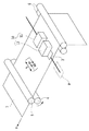
図1は、本発明のインクジェット記録装置の全体構成の概略を示す斜視図である。
Hereinafter, embodiments of the present invention will be described with reference to the drawings.
(First embodiment)
FIG. 1 is a perspective view schematically showing the overall configuration of the ink jet recording apparatus of the present invention.
図中の11は第1記録ヘッドであり、後述する5種類のインクがそれぞれ封入されたインクタンクと、それぞれのインクに対応したノズル列と、を一体化した構成となっている。12は第2記録ヘッドであり、第1記録ヘッド11と同様に構成されている。これらの記録ヘッド11,12(以下、これらをまとめて「記録ヘッド10」という)において、5種類のインクに対応したノズル列は、主走査方向(矢印X方向)において対称的に並ぶように配列されている。3は、記録ヘッド10を支持するキャリッジであり、画像の記録動作時に、記録ヘッド10と共に矢印Xの主走査方向に往復移動する。キャリッジ3は、非記録動作時などの待機時には、ホームポジションPに位置している。4は対の紙送りローラであり、補助ローラ5と共に記録媒体7を挟みながら矢印方向に回転することにより、記録媒体7を主走査方向と交差(本例の場合は、直交)する矢印Yの副走査方向に搬送する。6は給紙ローラであり、記録媒体7を挟みなが回転することにより、記録媒体7を給紙する。
In the figure,
記録動作時は、まず、ホームポジションPに位置しているキャリッジ3が矢印X1の往方向に移動する。記録ヘッド11,12は、キャリッジ3と共に往方向に移動しつつ、記録ヘッド11,12の一方が記録データに基づいて記録媒体7上にインクを吐出することにより、画像を記録する(往路記録動作)。記録媒体7の端部までの往路記録が終了した後、ローラ4,5,6が記録媒体7を矢印Yの副走査方向に所定量だけ搬送する(搬送動作)。その後、キャリッジ3が矢印X2の復方向の移動を開始する。記録ヘッド11,12は、キャリッジ3と共に復方向に移動しつつ、記録ヘッド11,12の他方が記録データに基づいて記録媒体7上にインクを吐出することにより、画像を記録する(復路記録動作)。記録媒体7の端部までの復路記録が終了した後、ローラ4,5,6が記録媒体7を矢印Yの副走査方向に所定量だけ搬送する(搬送動作)。このように、往路記録動作、搬送動作、復路記録動作、および搬送動作を繰り返すことにより、記録媒体7上に順次画像を記録する。本例においては、後述するように、記録媒体7上の同一領域に対して、記録ヘッド10(11,12)を複数回走査させることによって画像を記録するマルチパス記録方式を採用する。
During the recording operation, first, the carriage 3 located at the home position P moves in the forward direction of the arrow X1. While the recording heads 11 and 12 move in the forward direction together with the carriage 3, one of the
図2に、記録ヘッド10におけるノズル列の配列関係を示す。記録ヘッド11,12のそれぞれには、記録ヘッドの走査方向に並ぶようにノズル列が複数備えられている。
FIG. 2 shows the arrangement relationship of the nozzle rows in the
矢印X1の往方向においては、その上流側に第1記録ヘッド11が位置し、その下流側に第2記録ヘッド12が位置することになる。第1記録ヘッド11には、矢印X1の往方向の上流側から下流側に向かって、クリアインク、シアンインク(C)、マゼンタインク(M)、イエローインク(Y)、およびブラックインク(Bk)を吐出するノズル列が配列されている。それらのノズル列は、インクを吐出可能な複数のノズルが主走査方向と交差(本例の場合は、直交)する方向に配列されている。ノズルは、電気熱変換素子(ヒータ)やピエゾ素子などの吐出エネルギー発生素子を用いて、吐出口からインクを吐出可能な構成となっている。電気熱変換素子を用いた場合には、その発熱によりインクを発泡させ、その発泡エネルギーを利用して吐出口からインクを吐出することができる。
In the forward direction of the arrow X1, the
第2記録ヘッド12には、第1記録ヘッド11とは対称的に、往方向の上流側から下流側に向かって、ブラックインク(Bk)、イエローインク(Y)、マゼンタインク(M)、シアンインク(C)、およびクリアインクを吐出するノズル列が配列されている。往路記録動作時には、第1および第2記録ヘッド11,12の一方から上記5種のインクを吐出し、復路記録動作時には、第1および第2記録ヘッド11,12の他方から上記5種のインクを吐出する。これにより、往路記録動作時と復路記録動作時において、上記5種のインクの吐出順序を同一とし、吐出順序が異なることにより生じる記録画像の色ムラを防止することができる。本体の場合は、往路記録動作時に第1記録ヘッド11を用い、復路既読動作時に第2記録ヘッド12を用いる。
In contrast to the
クリアインクは透明なインクであり、本例の場合は、色材を含むC、M、Y、Bkの4色のカラーインク(Bkも含めて、色の付いたインクはカラーインクと称する)のいずれか1つと混合することによって固着する性質を持つ。記録媒体上でクリアインクとカラーインクが混合することによって、耐候性や耐擦過性に優れた記録物を作成することができる。クリアインクは、カラーインクよりも先に記録媒体に着弾させておくことにより、その効果を最大限に発揮することができる。そのため、クリアインクを吐出するノズル列は、記録動作時にカラーインクよりも先にクリアインクを吐出できるように、図2中左右の両側に配置した。
図3は、本発明のインクジェット記録装置の制御系の概略ブロック構成図である。記録装置は、ホストコンピュータ30から、記録情報を制御信号として受ける。記録情報は、記録装置内部の入出力インタフェイス21に一時保存されると同時に、記録装置内で処理可能なデータに変換されてから、記録ヘッド用駆動信号の供給手段を兼ねるCPU22に入力される。CPU22は、ROM23に保存されている制御プログラムに基づいて、CPU22に入力されたデータをRAM24等の周辺ユニットを用いて処理し、記録すべきデータ(画像データ)に変換する。
The clear ink is a transparent ink, and in the case of this example, four color inks of C, M, Y, and Bk including a color material (colored inks including Bk are referred to as color inks). It has the property of being fixed by mixing with any one of them. By mixing the clear ink and the color ink on the recording medium, a recorded matter having excellent weather resistance and scratch resistance can be produced. The clear ink can exert its effect to the maximum by landing on the recording medium before the color ink. Therefore, the nozzle rows that discharge clear ink are arranged on both the left and right sides in FIG. 2 so that the clear ink can be discharged before the color ink during the recording operation.
FIG. 3 is a schematic block diagram of the control system of the ink jet recording apparatus of the present invention. The recording apparatus receives recording information from the
また、CPU22は、画像データを記録媒体7上の所望の位置に記録すべく、画像データに同期して記録媒体7の搬送、および記録ヘッド10の移動を行なう駆動モータ26用のモータ駆動データを生成する。画像データおよびモータ駆動データは、それぞれヘッドドライバ27,28およびモータドライバ25を介して、記録ヘッド11,12および駆動モータ26に出力される。これにより、制御されたタイミングで画像が記録される。
The
記録装置は、画像の記録方式として、記録媒体7上の同一の記録領域に対して、記録ヘッド10を複数回走査させることによって画像を記録するマルチパス記録方式を採用している。マルチパス記録方式は、主走査方向に沿う1つの記録ラインを複数のノズルから吐出されるインクによって記録することになるため、ノズル毎のインク吐出量の差やインク吐出方向の微少な違いによる濃度ムラの発生を抑えることができる。 The recording apparatus employs a multi-pass recording method in which an image is recorded by scanning the recording head 10 a plurality of times for the same recording area on the recording medium 7 as an image recording method. In the multi-pass recording method, since one recording line along the main scanning direction is recorded by ink ejected from a plurality of nozzles, the density due to a difference in ink ejection amount for each nozzle or a slight difference in ink ejection direction. Generation of unevenness can be suppressed.
図4を用いて、マルチパス記録方式について説明する。本例の記録ヘッド10において、上記5種のインクを吐出する5つのノズル列Lのそれぞれは、第1および第2ノズル列L1,L2によって形成されている。第1ノズル列L1には、主走査方向と交差(本例の場合は、直交)する方向に沿って複数のノズルNが所定のピッチPで配列され、同様に、第2ノズル列L1にも複数のノズルNが所定のピッチPで配列されている。それらのノズル列L1,L2のノズルNは、半ピッチ(P/2)ずつずれている。結果的に、ノズル列Lは、複数のノズルNが(P/2)で配列されたノズル列を形成することになる。
The multi-pass recording method will be described with reference to FIG. In the
このようなノズル列Lは、マルチパス記録方式に応じて複数のノズル群に分割する。記録媒体7上の同一領域に対して、記録ヘッドの4回の走査によって画像を記録するマルチパス記録方式、つまり4パス記録法式の場合には、図4のように、第1ノズル群G1から第4ノズル群G4に4分割される。まず、1パス目の記録は第1ノズル群G1のノズルを用いて行い、その記録が終わった後、第1ノズル群G1の長さ分だけ記録媒体7を副走査方向に搬送する。次に、2パス目の記録を第2ノズル群G2のノズルを用いて行ってから、第2ノズル群G2の長さ分だけ記録媒体7を副走査方向に搬送する。3パス目、4パス目の記録も同様に行う。したがって、記録媒体7上の同一領域に対しては、このような4回のパスに分けて画像が記録されることになる。そのため、画像データは、4つのマスクパターンM1,M2,M3,M4によって4つに間引かれ、それらの間引かれた画像データに基づく4回のパスによって画像が記録される。図4のマスクパターンM1からM4は、後述するシアンインク用のマスクパターンであり、それぞれのノズル群は2つずつのノズル群部に分割され、それぞれのノズル群部毎にマスクパターンの間引き率が設定される。 Such a nozzle row L is divided into a plurality of nozzle groups according to the multi-pass printing method. In the case of a multi-pass recording method in which an image is recorded on the same area on the recording medium 7 by four scans of the recording head, that is, a 4-pass recording method, the first nozzle group G1 is used as shown in FIG. The fourth nozzle group G4 is divided into four. First, printing in the first pass is performed using the nozzles of the first nozzle group G1, and after the printing is finished, the recording medium 7 is conveyed in the sub-scanning direction by the length of the first nozzle group G1. Next, after the second pass printing is performed using the nozzles of the second nozzle group G2, the recording medium 7 is conveyed in the sub-scanning direction by the length of the second nozzle group G2. The third pass and the fourth pass are recorded in the same manner. Therefore, an image is recorded in the same area on the recording medium 7 in such four passes. Therefore, the image data is thinned into four by the four mask patterns M1, M2, M3, and M4, and the image is recorded by four passes based on the thinned image data. Mask patterns M1 to M4 in FIG. 4 are mask patterns for cyan ink, which will be described later. Each nozzle group is divided into two nozzle group portions, and the mask pattern thinning rate is set for each nozzle group portion. Is set.
次に、図5を用いて、インクを吐出する際に発生したインクミストの挙動について説明する。説明を簡略化するために、図5においては、第1記録ヘッド11が矢印X2の復方向に移動しつつ、2つのノズル列LA,LBからインクを吐出するときの様子を示す。ノズル列LAは、クリアインクを吐出するためのノズル列であり、ノズル列LBは、シアンインクを吐出するためのノズル列である。復路記録時は、第1記録ヘッド11が移動する矢印X2の復方向の下流側(図5中の左側)にノズル列LAが位置し、その上流側(図5中の右側)にノズル列LBが位置する。
Next, the behavior of ink mist generated when ink is ejected will be described with reference to FIG. In order to simplify the explanation, FIG. 5 shows a state in which the
これらのノズル列LA,LBからインクが吐出された際には、記録ヘッド11から記録媒体7に向かう気流A2,B2が生じる。これらの気流A2,B2は、記録媒体7に当たってから、走査方向の上流側と下流側に向かって広がり、下流側に広がった気流A1,B1は渦状となり、上流側に広がった気流A3,B3はそのまま上流(図5中の右方)に流れる。ノズル列LAから発生したクリアインクのインクミストの多くは、気流A1と気流A3に乗り、記録媒体7には着弾しない。気流A1に乗ったインクミストの一部は、記録ヘッド11の吐出口面FAに付着する。吐出口面FAは、ノズル列LAにおけるノズルの吐出口が形成されている面である。気流A3に乗ったインクミストは、ノズル列LB側に流れていく。記録媒体7と対向する記録ヘッド11の面はフラットな形状であるため、記録ヘッドと記録媒体との間の気流A3は整流となり、その気流A3に乗って流れるインクミストは乱されることなく、その形態が崩されることなくそのままノズル列LB流に流される。
When ink is ejected from these nozzle arrays LA and LB, airflows A2 and B2 from the
ノズル列LBからシアンインクが吐出された際には、そのシアンインクのインクミストがクリアインクのインクミストと同様の挙動を示す。吐出口面FBは、ノズル列LBにおけるノズルの吐出口が形成されている面である。気流B1には、気流A3に乗って流れてくるクリアインクのインクミストが含まれる。そのため、吐出口面FBには、クリアインクのインクミストとシアンインクのインクミストが混在して付着する。上述したように、クリアインクとシアンインクは混ざり合うことによって固着するため、それらの固着物が吐出口面FBに堆積し、ノズル列LBにおけるノズルがインクを適正に吐出できなくなるおそれがある。 When cyan ink is ejected from the nozzle row LB, the ink mist of the cyan ink exhibits the same behavior as the ink mist of the clear ink. The discharge port surface FB is a surface on which nozzle discharge ports in the nozzle row LB are formed. The airflow B1 includes ink mist of clear ink that flows on the airflow A3. Therefore, the ink mist of the clear ink and the ink mist of the cyan ink are mixedly attached to the ejection port surface FB. As described above, since the clear ink and the cyan ink adhere to each other when they are mixed, there is a possibility that the adhered matter accumulates on the ejection port surface FB, and the nozzles in the nozzle row LB cannot properly eject the ink.
図6に、ノズル列LA,LBに対応するマスクパターンの説明図である。図6(a)のシアンインク用のノズル列LBにおいて、同図中上下方向の端部寄りに位置するノズルに関しては、それに対応するマスクパターンによって間引かれた記録データによる記録比率が低く設定されている。ノズル列の端部に位置するノズルから吐出されたインクは、インクの吐出により生じる気流の影響により、その吐出方向がノズル列の中央寄りに傾く現象(「端ヨレ」ともいう)が生じて、インクの着弾位置がずれることがある。このような端ヨレを防止するために、シアンインク用のノズル列LBは、端部寄りに位置するノズルによる記録比率が低く設定され、それを補完するために、中央寄りに位置するノズルによる記録比率が高く設定されている。 FIG. 6 is an explanatory diagram of mask patterns corresponding to the nozzle rows LA and LB. In the cyan ink nozzle row LB in FIG. 6A, for the nozzles located near the end in the vertical direction in the same figure, the recording ratio by the recording data thinned out by the corresponding mask pattern is set low. ing. The ink ejected from the nozzles located at the end of the nozzle row has a phenomenon that the ejection direction is inclined toward the center of the nozzle row due to the influence of the air flow caused by the ink ejection (also referred to as “end deflection”), The ink landing position may shift. In order to prevent such end deviation, the cyan ink nozzle row LB is set to have a low recording ratio due to the nozzles located closer to the ends, and in order to compensate for this, recording using the nozzles located closer to the center is performed. The ratio is set high.
具体的には、図6(a)のように、ノズル列LBの第1ノズル群G1から第4ノズル群G4に対応するマスクパターンM1,M2,M3,M4を用いる。第1ノズル群G1は、2つのノズル群部G1A,G1Bに分けられている。同様に、第2ノズル群G2から第4ノズル群G4も2つずつのノズル群部に分けられている。マスクパターンM1によって間引かれた記録データによる記録比率は、ノズル群部G1Aに対応する記録データに関しては10%であり、ノズル群部G1Bに対応する記録データに関しては20%である。同様に、マスクパターンM2,M3,M4によって間引かれた記録データによる記録比率は、それぞれ2つずつのノズル群部に対応する2つの異なる値に設定されている。4パス記録方式において、ノズル群部G1A,G2A,G3A,G4Aによって記録される領域は同一領域であるため、それらに対応する記録比率の合計は100%(=10+30+40+20(%))となる。同様に、ノズル群部G1B,G2B,G3B,G4Bによって記録される領域に対応する記録比率の合計は、100%(=20+40+30+10(%))となる。 Specifically, as shown in FIG. 6A, mask patterns M1, M2, M3, and M4 corresponding to the first nozzle group G1 to the fourth nozzle group G4 of the nozzle row LB are used. The first nozzle group G1 is divided into two nozzle group parts G1A and G1B. Similarly, the second nozzle group G2 to the fourth nozzle group G4 are also divided into two nozzle group portions. The recording ratio by the recording data thinned out by the mask pattern M1 is 10% for the recording data corresponding to the nozzle group part G1A, and 20% for the recording data corresponding to the nozzle group part G1B. Similarly, the recording ratios based on the recording data thinned out by the mask patterns M2, M3, and M4 are set to two different values corresponding to two nozzle group portions, respectively. In the 4-pass printing method, the areas recorded by the nozzle group portions G1A, G2A, G3A, and G4A are the same area, so the total of the recording ratios corresponding to them is 100% (= 10 + 30 + 40 + 20 (%)). Similarly, the sum of the recording ratios corresponding to the areas recorded by the nozzle group parts G1B, G2B, G3B, G4B is 100% (= 20 + 40 + 30 + 10 (%)).
一方、図6(b)のクリアインク用のノズル列LAにおいて、中央寄りに位置するノズルに関しては、記録比率が低く設定され、それを補完するために、端部寄りに位置するノズルによる記録比率が高く設定されている。ノズル列LAの端部寄りに位置するノズルによる記録比率が高いために、上述した端ヨレの現象により、クリアインクの着弾位置のずれが発生するおそれがある。しかし、クリアインクが透明であること、および、クリアインクの着弾精度がカラーインクほど高く求められていないため、その端ヨレの影響は極めて小さい。 On the other hand, in the nozzle array LA for clear ink in FIG. 6B, the recording ratio is set low for the nozzles located near the center, and in order to compensate for this, the recording ratio by the nozzles located near the ends is set. Is set high. Since the recording ratio of the nozzles located near the end of the nozzle row LA is high, there is a possibility that the landing position of the clear ink may be shifted due to the phenomenon of the end deflection described above. However, since the clear ink is transparent and the landing accuracy of the clear ink is not required to be as high as that of the color ink, the influence of the end deviation is extremely small.
具体的には、図6(b)のように、ノズル列LAの第1ノズル群G11から第4ノズル群G14に対応するマスクパターンM11,M12,M13,M14を用いる。それらのマスクパターンM11,M12,M13,M14によって間引かれた記録データによる記録比率は、図6(a)のノズルLB用のマスクパターンと同様に、ノズル群部に応じて2つずつの異なる値に設定されている。ノズル群部G11A,G21A,G13A,G14Aによって記録される領域に対応する記録比率の合計は、100%(=40+20+10+30(%))となる。同様に、ノズル群部G11B,G12B,G13B,G14Bによって記録される領域に対応する記録比率の合計は、100%(=30+10+20+40(%))となる。 Specifically, as shown in FIG. 6B, mask patterns M11, M12, M13, and M14 corresponding to the first nozzle group G11 to the fourth nozzle group G14 of the nozzle array LA are used. The recording ratio by the recording data thinned out by the mask patterns M11, M12, M13, and M14 is different by two according to the nozzle group, similarly to the mask pattern for the nozzle LB in FIG. Is set to a value. The sum of the recording ratios corresponding to the areas recorded by the nozzle group portions G11A, G21A, G13A, and G14A is 100% (= 40 + 20 + 10 + 30 (%)). Similarly, the sum of the recording ratios corresponding to the areas recorded by the nozzle group portions G11B, G12B, G13B, and G14B is 100% (= 30 + 10 + 20 + 40 (%)).
このように、図6(a)のノズルLB用のマスクパターンM1からM4によって間引かれた記録データによる記録比率は、ノズル列LBの両端部側が低く、その中央部側が高く設定されていて、その記録比率の分布は山型の形状となっている。逆に、図6(b)のノズルLA用のマスクパターンM11からM14によって間引かれた記録データによる記録比率は、ノズル列LAの両端部側が高く、その中央部側が低く設定されていて、その記録比率の分布は谷型の形状となっている。このように、ノズルLB用のマスクパターンによる記録比率の分布形状と、ノズルLA用のマスクパターンによる記録比率の分布形状と、は、それらの谷部分と山部分とが対応するように逆形状となっている。 As described above, the recording ratio by the recording data thinned out by the mask patterns M1 to M4 for the nozzle LB in FIG. 6A is set to be low at both ends of the nozzle row LB and high at the center. The distribution of the recording ratio has a mountain shape. On the contrary, the recording ratio by the recording data thinned out by the mask patterns M11 to M14 for the nozzle LA in FIG. 6B is set to be high at both ends of the nozzle row LA and low at the center. The distribution of the recording ratio has a valley shape. As described above, the distribution shape of the recording ratio by the mask pattern for the nozzle LB and the distribution shape of the recording ratio by the mask pattern for the nozzle LA are opposite to each other so that the valley portion and the mountain portion correspond to each other. It has become.
以下に、このように記録比率の分布を逆形状としたことによる効果について説明する。 In the following, the effect obtained by making the distribution of the recording ratio in the opposite shape will be described.
記録ヘッドの吐出口面に対するインクミストの付着には、2つの要素が関係している。第1はインクミストの発生量であり、第2は、吐出口面に対するインクミストの付着のし易さの程度である。これら2つの要素は、記録比率が大きく関係している。インクミストの発生量は、記録比率が高いほど多くなり、そのが低いほど少なくなる。また、吐出口面に対するインクミストの付着のし易さの程度は、記録比率が高いほど高くなり、それが低いほど低くなる。すなわち、記録比率が低くなるほど、図5中の渦状の気流A1,B1が弱くなり、当然、吐出口面FA,FBへ向かう上昇気流も弱くなるため、インクミストは吐出口面FA,FBに付着し難くなる。 Two factors are related to the adhesion of ink mist to the ejection port surface of the recording head. The first is the amount of ink mist generated, and the second is the degree of ease with which the ink mist adheres to the ejection port surface. These two factors are greatly related to the recording ratio. The amount of ink mist generated increases as the recording ratio increases, and decreases as the recording ratio decreases. Further, the degree of easy ink mist adhesion to the ejection port surface increases as the recording ratio increases, and decreases as the recording ratio decreases. That is, as the recording ratio decreases, the spiral airflows A1 and B1 in FIG. 5 weaken, and naturally the rising airflow toward the discharge port surfaces FA and FB also weakens, so that the ink mist adheres to the discharge port surfaces FA and FB. It becomes difficult to do.
図7は、このような2つの要素と、マスクパターンによる記録比率と、の関係の説明図である。ノズル列LA,LBにおいて、図6中上下の端部寄りに位置するノズルの群を「端部ノズル群」、図6中上下方向における中央寄りに位置するノズルの群を「中央ノズル群」とする。 FIG. 7 is an explanatory diagram of the relationship between these two elements and the recording ratio based on the mask pattern. In the nozzle arrays LA and LB, a group of nozzles positioned near the upper and lower ends in FIG. 6 is referred to as an “end nozzle group”, and a group of nozzles positioned near the center in the vertical direction in FIG. To do.
シアンインク用のマスクパターンは山型形状であるため、ノズル列LBにおける中央ノズル群による記録比率は高く、その中央ノズル群からのインクミストの発生量が多く、それは吐出口面FBに付着しやすい。一方、クリアインク用のマスクパターンは谷型形状であるため、ノズル列LAにおける中央ノズル群による記録比率は低く、その中央ノズル群からのインクミストの発生量は少ない。このように、ノズル列LAの中央ノズル群から吐出されるクリアインクのインクミストが少ないため、そのインクミストがノズル列LB側の吐出口面FBに付着する量は低減される。逆に、ノズル列LAの端部ノズル群から吐出されるクリアインクのインクミストは多い。しかし、そのクリアインクのインクミストは、ノズル列LBの端部ノズル群から吐出されるシアンインクによって生じる渦状の気流B1が弱いため、ノズル列LB側の吐出口面FBに付着し難い。 Since the mask pattern for cyan ink has a mountain shape, the recording ratio of the central nozzle group in the nozzle row LB is high, and a large amount of ink mist is generated from the central nozzle group, which easily adheres to the ejection port surface FB. . On the other hand, since the mask pattern for clear ink has a valley shape, the recording ratio by the central nozzle group in the nozzle array LA is low, and the amount of ink mist generated from the central nozzle group is small. Thus, since the ink mist of the clear ink discharged from the central nozzle group of the nozzle row LA is small, the amount of the ink mist adhering to the discharge port surface FB on the nozzle row LB side is reduced. On the contrary, there is much ink mist of the clear ink ejected from the end nozzle group of the nozzle row LA. However, the ink mist of the clear ink hardly adheres to the discharge port surface FB on the nozzle row LB side because the spiral airflow B1 generated by the cyan ink discharged from the end nozzle group of the nozzle row LB is weak.
これらの結果、ノズル列LB側の吐出口面FBに対して、ノズル列LAから吐出されるクリアインクのインクミストが付着する量を低減することができる。したがって、クリアインクとシアンインクとが混ざり合った固着物が吐出口面FBに発生しに難くなり、端ヨレの影響を回避しつつ、ノズル列LBのインクの吐出状態を良好に維持することができる。 As a result, it is possible to reduce the amount of the clear ink ink mist that is ejected from the nozzle array LA to the ejection port surface FB on the nozzle array LB side. Therefore, it is difficult for the fixed matter in which the clear ink and the cyan ink are mixed to be generated on the discharge port surface FB, and the ink discharge state of the nozzle row LB can be maintained well while avoiding the influence of the end deviation. it can.
(第2の実施形態)
第1の実施形態においては、ノズル列の中央部または端部に対応するマスクパターンの記録比率が最も高く設定されている。つまり、ノズル列の中央を中心として記録比率が対象となるように、マスクパターンが設定されている。しかし、図8のように、インクの種類毎に、記録比率が最も高いマスクパターンに対応するノズルの位置をさまざまに設定してもよい。
(Second Embodiment)
In the first embodiment, the recording ratio of the mask pattern corresponding to the center or end of the nozzle row is set to be the highest. That is, the mask pattern is set so that the recording ratio is targeted around the center of the nozzle row. However, as shown in FIG. 8, the position of the nozzle corresponding to the mask pattern having the highest recording ratio may be set for each type of ink.
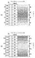
図8(a)は、クリアインクを吐出するノズル列L(S)における記録比率の分布であり、マスクパターンM23の一部およびマスクパターンM24の一部に対応するノズルによる記録比率が最も低く設定されている。図8(b)は、シアンインクを吐出するノズル列L(C)における記録比率の分布であり、マスクパターンM33の一部およびマスクパターンM34の一部に対応するノズルによる記録比率が最も高く設定されている。図8(c)は、マゼンタインクを吐出するノズル列L(M)における記録比率の分布であり、マスクパターンM42の一部およびマスクパターンM43の一部に対応するノズルによる記録比率が最も高く設定されている。図8(d)は、イエローインクを吐出するノズル列L(Y)における記録比率の分布であり、マスクパターンM51の一部およびマスクパターンM52の一部に対応するノズルによる記録比率が最も高く設定されている。インクの種類毎に、記録比率が最大となるピーク位置をずらすことによって、色ムラの発生を防止することができる。クリアインク吐出用のノズル列の記録比率の分布形状は、そのノズル列と走査方向の上流側に隣接するシアンインク吐出用のノズル列の記録比率の分布形状に対して、逆形状となっている。それは、前述した実施形態と同様に、クリアインクのインクミストが最も付着しやすいシアンインク吐出用のノズル列に対して、そのクリアンインクのインクミストの付着を抑えるためである。 FIG. 8A shows the distribution of the recording ratio in the nozzle row L (S) that discharges clear ink, and the recording ratio by the nozzles corresponding to a part of the mask pattern M23 and a part of the mask pattern M24 is set to the lowest. Has been. FIG. 8B shows the distribution of the recording ratio in the nozzle row L (C) that discharges cyan ink, and the recording ratio by the nozzles corresponding to a part of the mask pattern M33 and a part of the mask pattern M34 is set to be the highest. Has been. FIG. 8C shows the distribution of the printing ratio in the nozzle row L (M) that ejects magenta ink, and the printing ratio by the nozzles corresponding to a part of the mask pattern M42 and a part of the mask pattern M43 is set to the highest. Has been. FIG. 8D shows the distribution of the recording ratio in the nozzle row L (Y) that discharges yellow ink, and the recording ratio by the nozzles corresponding to a part of the mask pattern M51 and a part of the mask pattern M52 is set to be the highest. Has been. Occurrence of color unevenness can be prevented by shifting the peak position where the recording ratio becomes maximum for each type of ink. The distribution shape of the recording ratio of the nozzle array for clear ink ejection is opposite to the distribution ratio of the recording ratio of the nozzle array for cyan ink ejection adjacent to the nozzle array on the upstream side in the scanning direction. . The reason for this is to suppress the adhesion of the clear ink ink mist to the cyan ink ejection nozzle row to which the clear ink ink mist is most likely to adhere, as in the embodiment described above.
本例の場合は、前述した実施形態と同様に、走査方向の下流側から上流側に向かって、クリアインク用のノズル列、シアンインク用のノズル列、マゼンタインク用のノズル列、イエローインク用のノズル列、ブラックインク用のノズル列が順次隣接する。クリアインク用のノズル列L(S)の記録比率は谷型の分布形状であり、シアンインク用のノズル列L(C)の記録比率は山型の分布形状であり、それらは逆形状となっている。さらに本例の場合、前者の最大記録比率(40%)のノズル群部G21A,G24Bは、後者の最小記録比率(10%)のノズル群部31A,34Bに対応する。また、前者の最小記録比率(10%)のノズル群部G23B,G24Aは、後者の最大記録比率(40%)のノズル群部33B,34Aに対応する。また、前者の2番目に高い記録比率(30%)のノズル群部G21B,G22Aは、後者の2番目に低い記録比率(20%)のノズル群部31B,32Aに対応する。また、前者の2番目に低い記録比率(20%)のノズル群部G22B,G23Aは、後者の2番目に高い記録比率(30%)のノズル群部32B,33Aに対応する。 In this example, as in the above-described embodiment, from the downstream side to the upstream side in the scanning direction, the nozzle row for clear ink, the nozzle row for cyan ink, the nozzle row for magenta ink, and for yellow ink The nozzle row and the black ink nozzle row are adjacent to each other in sequence. The recording ratio of the clear ink nozzle row L (S) is a valley-shaped distribution shape, and the recording ratio of the cyan ink nozzle row L (C) is a mountain-shaped distribution shape, which are in reverse shapes. ing. Further, in the case of this example, the nozzle group portions G21A and G24B having the former maximum recording ratio (40%) correspond to the nozzle group portions 31A and 34B having the latter minimum recording ratio (10%). The former nozzle group portions G23B and G24A having the minimum recording ratio (10%) correspond to the nozzle group portions 33B and 34A having the latter maximum recording ratio (40%). Further, the nozzle group portions G21B and G22A having the second highest recording ratio (30%) correspond to the nozzle group portions 31B and 32A having the second lowest recording ratio (20%). Further, the nozzle group portions G22B and G23A having the second lowest recording ratio (20%) correspond to the nozzle group portions 32B and 33A having the second highest recording ratio (30%).
また、シアンインク用とマゼンタインク用のノズル列L(C),L(M)に関しては、それらの最大記録比率(40%)のノズルの位置は互いにずらされており、それらの最小記録比率(10%)のノズルの位置は、端ヨレを考慮して、いずれも端部寄りに位置している。すなわち、前者の最大記録比率のノズル群部G33B,G34Bと、後者の最大記録比率のノズル群部G42B,G43Aと、がずらされており、両者の端部に最小記録比率のノズル群部G31A,G34B,G41A,G44Bが位置する。 Further, regarding the nozzle rows L (C) and L (M) for cyan ink and magenta ink, the positions of the nozzles of the maximum recording ratio (40%) are shifted from each other, and the minimum recording ratio ( The positions of the nozzles of 10%) are all located closer to the end in consideration of the end deviation. That is, the nozzle group portions G33B and G34B having the maximum recording ratio of the former and the nozzle group portions G42B and G43A having the maximum recording ratio are shifted, and the nozzle group portions G31A and G31A having the minimum recording ratio are arranged at both ends. G34B, G41A, and G44B are located.
また、マゼンタインク用とイエローインク用のノズル列L(M),L(Y)に関しては、それらの最大記録比率(40%)のノズルの位置が互いにずらされている。また、それらの最小記録比率(10%)のノズルの位置は、端ヨレを考慮して、いずれも端部寄りに位置している。すなわち、前者の最大記録比率のノズル群部G42B,43Aと、後者の最大記録比率のノズル群部51B,52Aと、がずらされており、両者の端部に最小記録比率のノズル群部G41A,G44B,G51A,G54Bが位置する。 Further, regarding the nozzle rows L (M) and L (Y) for magenta ink and yellow ink, the positions of the nozzles having the maximum recording ratio (40%) are shifted from each other. Further, the positions of the nozzles having the minimum recording ratio (10%) are all located closer to the end portion in consideration of the end deviation. That is, the nozzle group portions G42B and 43A with the former maximum recording ratio and the nozzle group portions 51B and 52A with the latter maximum recording ratio are shifted, and the nozzle group portions G41A and G41A with the minimum recording ratio are located at both ends. G44B, G51A, and G54B are located.
また、イエローインク用とブラックインク用のノズル列の関係は、シアンインク用とマゼンタインク用のノズル列L(C),L(M)の関係、およびマゼンタインク用とイエローインク用のノズル列L(M),L(Y)の関係と同様とすることができる。 The relationship between the nozzle rows for yellow ink and black ink is the relationship between the nozzle rows L (C) and L (M) for cyan ink and magenta ink, and the nozzle row L for magenta ink and yellow ink. The relationship can be the same as the relationship between (M) and L (Y).
このように、搬送方向において隣接する3つのノズル列の記録比率を関係付けることにより、カラーインクの端ヨレの影響を回避しつつ、搬送方向の下流側のノズル列が上流側のノズル列に及ぼすインクミストの影響を小さく抑えることができる。 In this way, by relating the recording ratios of the three nozzle rows adjacent in the transport direction, the nozzle row on the downstream side in the transport direction affects the upstream nozzle row while avoiding the influence of the end deviation of the color ink. The influence of ink mist can be suppressed small.
(第3の実施形態)
前述した実施形態においては、ノズル列を複数の領域(ノズル群およびノズル群部)に分割し、その領域毎に記録比率を段階的に設定した。本実施形態においては、ノズル列を複数の領域に分割せずに、記録比率を設定する。
(Third embodiment)
In the embodiment described above, the nozzle row is divided into a plurality of regions (nozzle group and nozzle group portion), and the recording ratio is set stepwise for each region. In the present embodiment, the recording ratio is set without dividing the nozzle row into a plurality of regions.
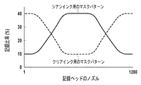
図9において、点線は、シアンインク用のマスクパターンにより設定される記録比率を示し、実線は、クリアインク用のマスクパターンにより設定される記録比率を示す。図8における横軸は、ノズル列に沿って配列された複数のノズルを示し、本例の場合は、ノズル番号1から1280の計1280ノズルが配列されている。シアンインクによる記録比率は、前述した実施形態と同様に、端ヨレの影響を回避するためにノズル列の両端部に位置するノズルの記録比率を低くし、それを補完するために、ノズル列の中央部に位置するノズルの記録比率を高く設定されている。ただし、その記録比率の分布は曲線によって現され、前述した実施形態のような階段状の分布形状ではなく滑らかに変化する分布形状となっている。つまり、その記録比率は、ノズル列の両端部側から中央部側に向かって徐々に高くなるように設定される。これにより、記録比率が階段状に変化するつなぎ部分のノズルによって生じやすいすじ状の画像の欠陥の発生を防止することができる。クリアインクによる記録比率は、シアンインクによる記録比率と逆の分布形状となっている。その記録比率は、ノズル列の両端部側から中央部側に向かって徐々に低くなるように設定される。
In FIG. 9, the dotted line indicates the recording ratio set by the mask pattern for cyan ink, and the solid line indicates the recording ratio set by the mask pattern for clear ink. The horizontal axis in FIG. 8 shows a plurality of nozzles arranged along the nozzle row. In this example, a total of 1280 nozzles having
(他の実施形態)
記録比率の分布形状は、複数の山部分あるいは複数の谷部分を含む形状であってもよい。また、記録ヘッドに備わる複数のノズル列の内、少なくとも2つのノズル列において、一方の記録比率の分布形状の山部分と、他方の記録比率の分布形状の谷部分と、が対応関係にあればよい。その2つのノズル列は、異なるインクを吐出するものであってもよく、同じインクを吐出するものであってもよく、また、必ずしも走査方向において隣接していなくてもよい。
(Other embodiments)
The distribution shape of the recording ratio may be a shape including a plurality of peak portions or a plurality of valley portions. In addition, in at least two nozzle rows of the plurality of nozzle rows provided in the print head, if there is a correspondence between the peak portion of one print ratio distribution shape and the valley portion of the other print ratio distribution shape Good. The two nozzle rows may eject different inks, may eject the same ink, and may not necessarily be adjacent in the scanning direction.
3 キャリッジ
7 記録媒体
10 記録ヘッド
22 CPU
LA クリアインク吐出用のノズル列
LB シアンインク吐出用のノズル列
M1,M2,M3,M4 シアンインク用のマスクパターン
M11,M12,M13,M14 クリアインク用のマスクパターン
3 Carriage 7
LA Clear ink ejection nozzle row LB Cyan ink ejection nozzle row M1, M2, M3, M4 Mask pattern for cyan ink M11, M12, M13, M14 Mask pattern for clear ink
Claims (18)
前記記録ヘッドを記録媒体上の単位領域に対して前記走査方向に相対的にN回走査させる走査手段と、
前記複数の吐出口列のそれぞれをN個に分割してなるN個の吐出口群のうちの1つの吐出口群に対応する距離だけ、前記走査手段による走査と走査の間に前記記録媒体を前記記録ヘッドに対して前記走査方向と交差する搬送方向に相対的に搬送させる搬送手段と、
前記複数の吐出口列の前記N個の吐出口群のそれぞれに対して記録比率を設定する設定手段と、
前記N回の走査のそれぞれにおいて、前記設定手段により設定された前記記録比率にしたがって前記N個の吐出口群のそれぞれから前記単位領域にインクを吐出させるように制御する制御手段と、を有するインクジェット記録装置であって、
前記設定手段は、前記N個の吐出口群のうちの第1の吐出口群と、前記第1の吐出口群よりも前記配列方向において前記複数の吐出口列の一方の端部に近く、且つ、前記複数の吐出口列の中央部から遠い第2の吐出口群と、に関し、(i)前記第1の吐出口列内の前記第2の吐出口群の記録比率が、前記第1の吐出口列内の前記第1の吐出口群の記録比率よりも低くなり、(ii)前記第2の吐出口列内の前記第1の吐出口群の記録比率が、前記第2の吐出口列内の前記第2の吐出口群の記録比率よりも低くなり、(iii)前記第2の吐出口列内の前記第1の吐出口群の記録比率が、前記第1の吐出口列内の前記第1の吐出口群の記録比率よりも低くなるように、前記記録比率を設定することを特徴とするインクジェット記録装置。 A first ejection port array in which a plurality of ejection ports for ejecting the first type of ink are arranged in the arrangement direction, and a plurality of inks for ejecting a second type of ink different from the first type A recording head in which a plurality of discharge port arrays including at least a second discharge port array in which the discharge ports are arranged in the arrangement direction are arranged side by side in a scanning direction intersecting the arrangement direction;
Scanning means for scanning the recording head relative to the unit area on the recording medium N times in the scanning direction;
The recording medium is scanned between the scans by the scanning means by a distance corresponding to one discharge port group among N discharge port groups obtained by dividing each of the plurality of discharge port arrays into N. Transport means for transporting the recording head relative to a transport direction intersecting the scanning direction;
Setting means for setting a recording ratio for each of the N discharge port groups of the plurality of discharge port arrays;
Control means for controlling each of the N ejection openings to eject ink from each of the N ejection orifice groups in accordance with the recording ratio set by the setting means in each of the N scans. A recording device,
The setting means, said the first outlet group of the N outlet groups, rather close to one end of the first discharge opening the plurality of outlet rows in the array direction than the group And (i) a recording ratio of the second discharge port group in the first discharge port row is the second discharge port group far from the center of the plurality of discharge port rows . (Ii) the recording ratio of the first ejection port group in the second ejection port group is lower than the recording rate of the first ejection port group in one ejection port array. (Iii) the recording ratio of the first ejection port group in the second ejection port group is lower than the recording rate of the second ejection port group in the ejection port array. An ink jet recording apparatus, wherein the recording ratio is set to be lower than a recording ratio of the first ejection port group in the row.
前記設定手段は、(i)前記第1の吐出口列内の前記第3の吐出口群の記録比率が、前記第1の吐出口列内の前記第1の吐出口群の記録比率よりも低くなり、(ii)前記第2の吐出口列内の前記第1の吐出口群の記録比率が、前記第2の吐出口列内の前記第3の吐出口群の記録比率よりも低くなるように、前記記録比率を設定することを特徴とする請求項1から4のいずれか1項に記載のインクジェット記録装置。 The N of the discharge port groups, said proximal rather the other end of said plurality of discharge port arrays at a first of said array direction than the outlet groups, and further from the central portion of the plurality of outlet rows A third discharge port group;
(I) the recording ratio of the third ejection port group in the first ejection port array is greater than the recording ratio of the first ejection port group in the first ejection port array; (Ii) The recording ratio of the first ejection port group in the second ejection port array is lower than the recording ratio of the third ejection port group in the second ejection port array. The inkjet recording apparatus according to any one of claims 1 to 4, wherein the recording ratio is set as described above.
前記N個の吐出口群は、前記第2の吐出口群よりも前記配列方向において前記複数の吐出口列の前記一方の端部から遠い第4の吐出口群を更に含み、
前記設定手段は、(i)前記第3の吐出口列内の前記第2の吐出口群の記録比率が、前記第3の吐出口列内の前記第4の吐出口群の記録比率よりも低くなり、(ii)前記第2の吐出口列内の前記第4の吐出口群の記録比率が、前記第2の吐出口列内の前記第2の吐出口群の記録比率よりも低くなり、(iii)前記第2の吐出口列内の前記第4の吐出口群の記録比率が、前記第3の吐出口列内の前記第4の吐出口群の記録比率よりも低くなるように、前記記録比率を設定することを特徴とする請求項1から6のいずれか1項に記載のインクジェット記録装置。 The plurality of ejection port arrays includes a third ejection port array in which a plurality of ejection ports for ejecting a third type of ink different from the first and second types of ink are arranged in the arrangement direction. In addition,
The N discharge port groups further include a fourth discharge port group farther from the one end of the plurality of discharge port arrays in the arrangement direction than the second discharge port group,
The setting means includes: (i) a recording ratio of the second ejection port group in the third ejection port array is greater than a recording ratio of the fourth ejection port group in the third ejection port array. (Ii) The recording ratio of the fourth ejection port group in the second ejection port array is lower than the recording ratio of the second ejection port group in the second ejection port array. (Iii) The recording ratio of the fourth outlet group in the second outlet array is lower than the recording ratio of the fourth outlet group in the third outlet array. The ink jet recording apparatus according to claim 1, wherein the recording ratio is set.
前記設定手段は、前記N個のマスクパターンのそれぞれにおける間引き率に基づいて前記記録比率を設定することを特徴とすることを特徴とする請求項1から11のいずれか1項に記載のインクジェット記録装置。 Based on the data corresponding to the image to be recorded in the unit area and the N mask patterns corresponding to each of the N ejection port groups, the ink of the controller by the control means in each of the N scans. It further has a generating means for generating N pieces of print data used when performing ejection,
The inkjet recording according to any one of claims 1 to 11, wherein the setting unit sets the recording ratio based on a thinning rate in each of the N mask patterns. apparatus.
前記第2の種類のインクは、色材を含有しないインクであることを特徴とする請求項1から12のいずれか1項に記載のインクジェット記録装置。 The first type of ink is an ink containing a color material,
The inkjet recording apparatus according to claim 1, wherein the second type of ink is an ink that does not contain a color material.
前記第2の種類のインクは、色材を含有しないインクであり、
前記第3の種類のインクは、前記第1の色材と異なる第2の色材を含有するインクであることを特徴とする請求項7または8に記載のインクジェット記録装置。 The first type of ink is an ink containing a first color material,
The second type of ink is an ink that does not contain a coloring material,
9. The ink jet recording apparatus according to claim 7, wherein the third type of ink is an ink containing a second color material different from the first color material.
前記記録ヘッドを前記記録媒体上の単位領域に対して前記走査方向に相対的にN回走査させる走査工程と、
前記複数の吐出口列のそれぞれをN個に分割してなるN個の吐出口群のうちの1つの吐出口群に対応する距離だけ、前記走査工程による走査と走査の間に前記記録媒体を前記記録ヘッドに対して前記走査方向と交差する搬送方向に相対的に搬送させる搬送工程と、
前記複数の吐出口列の前記N個の吐出口群のそれぞれに対して記録比率を設定する設定工程と、
前記N回の走査のそれぞれにおいて、前記設定工程により設定された前記記録比率にしたがって前記N個の吐出口群のそれぞれから前記単位領域にインクを吐出させるように制御する制御工程と、を有するインクジェット記録方法であって、
前記設定工程は、前記N個の吐出口群のうちの第1の吐出口群と、前記第1の吐出口群よりも前記配列方向において前記複数の吐出口列の一方の端部に近く、且つ、前記複数の吐出口列の中央部から遠い第2の吐出口群と、に関し、(i)前記第1の吐出口列内の前記第2の吐出口群の記録比率が、前記第1の吐出口列内の前記第1の吐出口群の記録比率よりも低くなり、(ii)前記第2の吐出口列内の前記第1の吐出口群の記録比率が、前記第2の吐出口列内の前記第2の吐出口群の記録比率よりも低くなり、(iii)前記第2の吐出口列内の前記第1の吐出口群の記録比率が、前記第1の吐出口列内の前記第1の吐出口群の記録比率よりも低くなるように、前記記録比率を設定することを特徴とするインクジェット記録方法。 A first ejection port array in which a plurality of ejection ports for ejecting the first type of ink are arranged in the arrangement direction, and a plurality of inks for ejecting a second type of ink different from the first type A plurality of ejection port arrays including at least a second ejection port array in which the ejection ports are arranged in the arrangement direction are arranged on a recording medium using a recording head in which the ejection ports are arranged in a scanning direction intersecting the arrangement direction. An inkjet recording method for recording an image, comprising:
A scanning step of causing the recording head to scan N times relative to the unit area on the recording medium in the scanning direction;
The recording medium is moved between scans in the scanning step by a distance corresponding to one discharge port group of N discharge port groups obtained by dividing each of the plurality of discharge port arrays into N. A transport step of transporting the recording head in a transport direction that intersects the scanning direction;
A setting step of setting a recording ratio for each of the N discharge port groups of the plurality of discharge port arrays;
A control step of controlling each of the N scans to discharge ink to each of the unit areas from each of the N discharge port groups according to the recording ratio set by the setting step. A recording method,
Said setting step, the N and the first outlet group of the outlet groups, near rather in said array direction than the first outlet group in one end portion of said plurality of discharge port arrays And (i) a recording ratio of the second discharge port group in the first discharge port row is the second discharge port group far from the center of the plurality of discharge port rows . (Ii) the recording ratio of the first ejection port group in the second ejection port group is lower than the recording rate of the first ejection port group in one ejection port array. (Iii) the recording ratio of the first ejection port group in the second ejection port group is lower than the recording rate of the second ejection port group in the ejection port array. An ink jet recording method, wherein the recording ratio is set to be lower than a recording ratio of the first ejection port group in the row.
Priority Applications (1)
| Application Number | Priority Date | Filing Date | Title |
|---|---|---|---|
| JP2011109261A JP5825840B2 (en) | 2011-05-16 | 2011-05-16 | Inkjet recording apparatus and inkjet recording method |
Applications Claiming Priority (1)
| Application Number | Priority Date | Filing Date | Title |
|---|---|---|---|
| JP2011109261A JP5825840B2 (en) | 2011-05-16 | 2011-05-16 | Inkjet recording apparatus and inkjet recording method |
Publications (3)
| Publication Number | Publication Date |
|---|---|
| JP2012240224A JP2012240224A (en) | 2012-12-10 |
| JP2012240224A5 JP2012240224A5 (en) | 2014-07-24 |
| JP5825840B2 true JP5825840B2 (en) | 2015-12-02 |
Family
ID=47462440
Family Applications (1)
| Application Number | Title | Priority Date | Filing Date |
|---|---|---|---|
| JP2011109261A Expired - Fee Related JP5825840B2 (en) | 2011-05-16 | 2011-05-16 | Inkjet recording apparatus and inkjet recording method |
Country Status (1)
| Country | Link |
|---|---|
| JP (1) | JP5825840B2 (en) |
Families Citing this family (2)
| Publication number | Priority date | Publication date | Assignee | Title |
|---|---|---|---|---|
| JP6566190B2 (en) * | 2015-03-20 | 2019-08-28 | セイコーエプソン株式会社 | Recording apparatus and recording method |
| JP6520298B2 (en) * | 2015-03-27 | 2019-05-29 | セイコーエプソン株式会社 | Droplet discharge apparatus and droplet discharge method |
Family Cites Families (3)
| Publication number | Priority date | Publication date | Assignee | Title |
|---|---|---|---|---|
| JP2001138554A (en) * | 1999-11-11 | 2001-05-22 | Canon Inc | Ink jet recording method and ink jet recorder |
| JP4817520B2 (en) * | 2001-04-02 | 2011-11-16 | キヤノン株式会社 | Inkjet recording apparatus and inkjet recording method |
| JP4652770B2 (en) * | 2003-12-04 | 2011-03-16 | キヤノン株式会社 | Inkjet recording method, inkjet recording apparatus, and data processing method |
-
2011
- 2011-05-16 JP JP2011109261A patent/JP5825840B2/en not_active Expired - Fee Related
Also Published As
| Publication number | Publication date |
|---|---|
| JP2012240224A (en) | 2012-12-10 |
Similar Documents
| Publication | Publication Date | Title |
|---|---|---|
| JP4717620B2 (en) | Inkjet recording method and inkjet recording apparatus | |
| JP5247006B2 (en) | Inkjet recording apparatus and inkjet recording method | |
| JP5105777B2 (en) | Image processing method and inkjet recording apparatus | |
| WO2006064820A1 (en) | Ink jet recording method and ink jet recording device | |
| JP6095398B2 (en) | Recording apparatus and recording method | |
| JP2007015260A (en) | Recorder and its controlling method | |
| JP2002166578A (en) | Method and apparatus for ink jet recording | |
| US6460976B1 (en) | Printing apparatus having control means of controlling timing for driving blocks of print elements | |
| JP2011005703A (en) | Ink jet recording apparatus and ink jet recording method | |
| JP4566397B2 (en) | Inkjet recording apparatus and inkjet recording method | |
| US7971951B2 (en) | Inkjet printing apparatus and printing method therefor | |
| US8955934B2 (en) | Fluid ejecting apparatus and fluid ejecting method | |
| JP2002166534A (en) | Apparatus and method for ink jet recording | |
| JP5825840B2 (en) | Inkjet recording apparatus and inkjet recording method | |
| JP5570107B2 (en) | Inkjet recording apparatus and inkjet recording method | |
| JP5972037B2 (en) | Inkjet recording apparatus and inkjet recording method | |
| JP2005205636A (en) | Inkjet recorder and method of inkjet recording | |
| JP4455038B2 (en) | Inkjet recording method and inkjet recording apparatus | |
| JP5273919B2 (en) | Inkjet recording method and inkjet recording apparatus | |
| JP6323039B2 (en) | PRINT CONTROL DEVICE, PRINT CONTROL METHOD, AND PROGRAM | |
| JP5538752B2 (en) | Recording apparatus, recording method, and image processing apparatus | |
| JP5593799B2 (en) | Fluid ejecting apparatus and fluid ejecting method | |
| JP5787474B2 (en) | Image processing apparatus, image processing method, and program | |
| JP5560679B2 (en) | Fluid ejecting apparatus and fluid ejecting method | |
| JP5832138B2 (en) | Inkjet recording apparatus and inkjet recording method |
Legal Events
| Date | Code | Title | Description |
|---|---|---|---|
| A621 | Written request for application examination |
Free format text: JAPANESE INTERMEDIATE CODE: A621 Effective date: 20140514 |
|
| A521 | Request for written amendment filed |
Free format text: JAPANESE INTERMEDIATE CODE: A523 Effective date: 20140606 |
|
| A977 | Report on retrieval |
Free format text: JAPANESE INTERMEDIATE CODE: A971007 Effective date: 20150206 |
|
| A131 | Notification of reasons for refusal |
Free format text: JAPANESE INTERMEDIATE CODE: A131 Effective date: 20150217 |
|
| A521 | Request for written amendment filed |
Free format text: JAPANESE INTERMEDIATE CODE: A523 Effective date: 20150420 |
|
| TRDD | Decision of grant or rejection written | ||
| A01 | Written decision to grant a patent or to grant a registration (utility model) |
Free format text: JAPANESE INTERMEDIATE CODE: A01 Effective date: 20150915 |
|
| A61 | First payment of annual fees (during grant procedure) |
Free format text: JAPANESE INTERMEDIATE CODE: A61 Effective date: 20151013 |
|
| R151 | Written notification of patent or utility model registration |
Ref document number: 5825840 Country of ref document: JP Free format text: JAPANESE INTERMEDIATE CODE: R151 |
|
| LAPS | Cancellation because of no payment of annual fees |