JP4566397B2 - Inkjet recording apparatus and inkjet recording method - Google Patents
Inkjet recording apparatus and inkjet recording method Download PDFInfo
- Publication number
- JP4566397B2 JP4566397B2 JP2000365562A JP2000365562A JP4566397B2 JP 4566397 B2 JP4566397 B2 JP 4566397B2 JP 2000365562 A JP2000365562 A JP 2000365562A JP 2000365562 A JP2000365562 A JP 2000365562A JP 4566397 B2 JP4566397 B2 JP 4566397B2
- Authority
- JP
- Japan
- Prior art keywords
- recording
- scanning
- sub
- ejection port
- ink
- Prior art date
- Legal status (The legal status is an assumption and is not a legal conclusion. Google has not performed a legal analysis and makes no representation as to the accuracy of the status listed.)
- Expired - Fee Related
Links
Images


Classifications
-
- B—PERFORMING OPERATIONS; TRANSPORTING
- B41—PRINTING; LINING MACHINES; TYPEWRITERS; STAMPS
- B41J—TYPEWRITERS; SELECTIVE PRINTING MECHANISMS, i.e. MECHANISMS PRINTING OTHERWISE THAN FROM A FORME; CORRECTION OF TYPOGRAPHICAL ERRORS
- B41J11/00—Devices or arrangements of selective printing mechanisms, e.g. ink-jet printers or thermal printers, for supporting or handling copy material in sheet or web form
- B41J11/36—Blanking or long feeds; Feeding to a particular line, e.g. by rotation of platen or feed roller
- B41J11/42—Controlling printing material conveyance for accurate alignment of the printing material with the printhead; Print registering
- B41J11/425—Controlling printing material conveyance for accurate alignment of the printing material with the printhead; Print registering for a variable printing material feed amount
Landscapes
- Ink Jet (AREA)
Description
【0001】
【発明の属する技術分野】
本発明は、記録手段から被記録材へインクを吐出して記録を行うインクジェット記録装置に関する。
【0002】
【従来の技術】
プリンタ、複写機、ファクシミリ等の機能を有する記録装置、あるいはコンピューターやワードプロセッサ等を含む複合型電子機器やワークステーションなどの出力機器として用いられる記録装置は、文字や線画等の情報を含む画像情報に基づいて用紙やプラスチック薄板等の被記録媒体に文字や線画等を含む画像を記録するように構成されている。前記記録装置は、記録方式により、インクジェット式、ワイヤドット式、サーマル式、レーザービーム式等に分けることができる。上記記録装置のうち、インクジェット式の記録装置(以下、インクジェット記録装置とも称する)は、記録手段(以下、記録ヘッドとも称する)から被記録媒体にインクを吐出して記録を行うものであり、他の記録方式に比べて高精細化が容易であり、また、高速で静粛性に優れ、かつ安価であるという優れた特徴を有する。
【0003】
また、近年においては、高精彩なカラー画像を出力可能な記録装置のニーズも高まりつつあり、複数の色のインクを吐出してカラー画像を記録可能なカラーインクジェット記録装置も数多く開発されている。
【0004】
上述のようなインクジェット記録装置としては、記録速度の向上のため、複数の記録素子を集積配列してなる記録ヘッドとして、インク吐出部としてのインク吐出口及び液路を複数集積したものを用い、さらにカラー対応として、複数個の前記記録ヘッドを備えたものが一般的である。
【0005】
図1は前記記録ヘッドで記録紙面上を印字していく際のプリンタ部の構成を示したものである。同図において、101で示す各構成はインクカートリッジである。これらは、ブラック、シアン、マゼンタ、イエローの4色のカラーインクがそれぞれ詰め込まれたインクタンクと、記録ヘッド102により構成されている。この記録ヘッド102には、複数の吐出口からなる吐出口列が形成されている。図2は、記録ヘッド102上に配列される複数の吐出口の様子を、図1に示す矢印z方向から見た概略図である。図2において、201は記録ヘッド102上に複数配列された吐出口である。
【0006】
また、図1において、103は紙送りローラで104の補助ローラとともに記録紙Pを抑えながら図の矢印の方向に回転し、記録紙Pをy方向に随時送っていく。また105は給紙ローラであり記録紙の給紙を行うとともに、103、104と同様、記録紙Pを抑える役割も果たす。106は4つのインクカートリッジを支持し、印字とともにこれらを移動させるキャリッジである。これは印字を行っていないとき、あるいは記録ヘッドの回復作業などを行うときには、図の点線で示したホームポジション(h)に待機するようになっている。
【0007】
印字開始前、ホームポジションにあるキャリッジ106は、印字開始命令がくると、図1において矢印Xで示す方向へ沿って移動しながら、記録ヘッド102の吐出口面に形成された複数の吐出口201より、記録データに従ってインクを吐出することで記録を行う。紙面端部までデータの印字が終了するとキャリッジは元のホームポジションに戻り、再びX方向に対する移動とともに印字を行う。
【0008】
イメージ画像等を印字する場合には、発色性、階調性、一様性など様々な要素が必要となる。特に一様性に関しては、記録ヘッド製造工程で生じるわずかなノズル単位のばらつきが、印字したときに、各ノズルのインクの吐出量や吐出方向の向きに影響を及ぼし、最終的には印字画像の濃度ムラとして画像品位を劣化させる原因となることが知られている。
【0009】
その具体例を図3、図4を用いて説明する。図3(a)において、31は記録ヘッドを模式的に示した図であり、この記録ヘッド31に設けられるノズル列は、8個のノズル32によって構成されている。また、33はノズル32よって吐出されたインクドロップレット(以下、「インク滴」もしくは単に「インク」とも称する。)を示している。また、図3(b)は、記録ヘッド31のノズル列により周期的にインクを吐出して形成した画像の一例を示しており、この図では、記録ヘッドを移動させながら、各ノズルにより8ドットずつ記録を行った例を示している。また、図3(c)は、図3(b)に示す画像の光学濃度を示すグラフであり、この図3(c)では、横軸が濃度に対応している。
【0010】
記録ヘッド31から吐出されるインク滴は、図3(a)に示すように揃った吐出量で、揃った方向に吐出されるのが理想である。このように理想的に吐出が行われれば、図3(b)に示したように紙面上に揃った大きさのドットが着弾され、その結果、図3(c)に示すように、全体的にも濃度ムラの無い一様な画像が得られることとなる。
【0011】
しかし、実際には先にも述べたようにノズル1つ1つにはそれぞれバラツキがあり、そのまま図3に示すようにインクを吐出して印字を行うと、ノズルより吐出されるインクドロップの大きさ及び向きのバラツキが原因となって濃度ムラを生じてしまう。
【0012】
図4は、記録ヘッドの複数のノズルにばらつきが生じた場合の、濃度ムラを説明する模式図である。図4(a)、(b)、(c)は、それぞれ、図3(a)、(b)、(c)に対応するものであり、それぞれ比較することで、理想的に記録が行われる状態と、複数のノズルにばらつきがあって記録が行われる状態とを対比することができる。
【0013】
図4(a)は、記録ヘッドと、記録ヘッドのノズルから吐出されるインク滴の大きさや方向にばらつきが生じている状態を示している。図4(a)に示すようにそれぞれのノズルより吐出されるインクドロップの大きさ及び向きにバラツキがあった場合、紙面上においては図4(b)に示すように着弾される。この図によれば、ヘッド主走査方向に対し、周期的にエリアファクター100%を満たせない白紙の部分が存在したり、また逆に必要以上にドットが重なり合ったり、あるいはこの図中央に見られる様な白スジが発生したりしている。この様な状態で着弾されたドットの集まりはノズル並び方向に対し、図4(c)に示した濃度分布となり、結果的には、通常人間の目でみた限りで、これらの現象が濃度ムラとして感知される。また、紙送り量のバラツキに起因するスジも目立つ場合がある。
【0014】
上述したような濃度ムラの対策として、特開平06−143618号公報には、濃度ムラを低減させる方法が開示されている。以下、図5を参照して、その方法を簡単に説明する。
【0015】
図5に示す記録動作は、図3(b)、図4(b)で示した記録領域を、記録ヘッド31を3回走査することにより完成させるものであり、図5(a)に示す31a、31b、31cは、それぞれ1回目、2回目、3回目の走査における記録ヘッド31の相対位置を表している。この記録動作では、記録ヘッドを走査する毎に、副走査方向(図においては記録ヘッドのノズルの配列方向)へ沿って記録ヘッド31と記録紙とを相対移動させており、また、その相対移動の量は、記録ヘッド31に設けられる8ノズルの半分に対応した量である。
【0016】
この図5に示す記録動作の方法によると図3(b)、図4(b)で示した印字領域に対して記録ヘッド31を3回走査しているが、印字領域の半分、つまり、4ノズル分に対応する領域は、記録ヘッドの2回の走査(以下、2パス)で完成している。この場合記録ヘッドの8個のノズルは、上側の4ノズルと下側の4ノズルの2グループに分けられ、1ノズルが1回の主走査で印字するドットは、規定の画像データを、ある所定の画像データ配列に従い、約半分に間引いたものである。そして2回目の主走査時に残りの半分の画像データへドットを埋め込み、4画素単位領域の印字を完成させる。以上の様な記録方法を、以下マルチパス記録方法と称す。尚、図5に示す記録方法は、所定の領域が2回の走査で完成されていることから、2パス記録方法とも称する。
【0017】
この様な記録方法を用いると、図4で示した記録ヘッドと等しいものを使用しても、各ノズル固有の印字画像への影響が半減されるので、印字された画像は図5(b)の様になり、図4(b)のような黒スジや白スジが余り目立たなくなる。従って、濃度ムラも図5(c)に示す様に図4の場合と比べ、かなり緩和される。この様な記録を行う際、1主走査目と2主走査目では、画像データをある決まった配列に従い互いに埋め合わせる形で分割するが、通常この画像データ配列とは図6に示すように、縦横1画素おきの、千鳥格子状になるようなものを用いるのが最も一般的である。従って、単位印字領域(ここでは4画素単位)に於いては千鳥格子を印字する1主走査目と、逆千鳥格子(1走査目とは逆のパターン)を印字する2主走査目によって印字が完成されるものである。図6の(a)、(b)及び(c)は、それぞれこの千鳥、逆千鳥の間引きパターンを用いたときに一定の領域の記録がどのようになされていくかを、説明するためのものである。なお、この図6においても、31a、31b、31cは、それぞれ1回目、2回目、3回目の走査における記録ヘッド31の相対位置を示すものである。
【0018】
図6において、まず1主走査目では、下4ノズルを用いて千鳥の間引きパターンの記録を行う(図6(a))。次に2主走査目には紙送りを4画素(ヘッド長の1/2)だけ行い、逆千鳥の間引きパターンの記録を行う(図6(b))。更に3主走査目には再び4画素(ヘッド長の1/2)だけの紙送りを行い、再び千鳥の間引きパターンの記録を行う(図6(c))。この様にして順次4画素単位の紙送りと、千鳥、逆千鳥の間引きパターンの記録を交互に行うことにより、4画素単位の記録領域を1主走査毎に完成させていく。
【0019】
以上説明したように、同じ領域内に異なる2種類のノズルにより画像が完成されていくことにより、濃度ムラの無い高画質な画像を得ることが可能である。
【0020】
また、特開平06−135014号公報は、黒画像とカラー画像の隣接境界におけるにじみを防止した高品位な画像を記録する技術を開示している。その方法を簡単に説明すると、ブラックインクで印字を行う黒画像とカラーインクで印字を行うカラー画像が隣接する場合には、黒画像を形成する走査(上記X方向への走査)とカラー画像を記録する走査(上記X方向への走査)とが連続して行われないようにブラックインク吐出用の吐出群のうち所定の吐出部を使用する事で、黒画像とカラー画像の隣接境界におけるにじみ(ブリード)を防止した高品位な画像記録を達成させている。
【0021】
【発明が解決しようとする課題】
しかしながら、上記特開平06−135014号公報には、前述のマルチパス記録や、記録媒体を搬送する搬送量を2種類以上備えた記録に関する記載は無い。
【0022】
上述したマルチパス記録方法における色間のにじみに着目して検討したところ、マルチパス記録方法を適用した場合に、1回の記録ヘッドの走査により画像を完成させる1パス記録方法と異なる特性のにじみが発生することがわかった。
【0023】
また、にじみ以外に、複数色のインクが記録媒体に着弾したときの、記録媒体上におけるインク滴の押し合いにより記録部が白っぽくなる現象についても、上記1パス記録方法により記録を行ったときと上記マルチパス記録方法により記録を行ったときとでは異なる。これらの現象の差は、マルチパス記録方法が濃度ムラを防止する効果以外に、所定の単位面積に対して単位時間あたりに記録するドット数が少ないことで、記録媒体に対する浸透状態やインクの定着状態が1パス記録方法と異なることに起因している。
【0024】
また、記録媒体を搬送する搬送量を2種類以上備えた記録において、マルチパス記録方法により、少なくとも2種類の吐出口列からインク吐出を行い各々の画像領域を完成させる場合に、第1の吐出口列で完成させる第1の画像領域と第2の吐出口列で完成させる第2の画像領域の重複画像領域内で、画像完成の時間差がある領域間で色ムラが発生した。この現象は、第1の吐出口列で完成させられた第1の画像領域の記録媒体への浸透状態やインクの定着状態が時間に応じて変化しているため、このように時間に応じて状態変化している第1の画像領域に、第2の吐出口列から吐出されたインクが重複又は隣接すると、重複又は隣接するまでの時間に応じて重複又は隣接したインクの記録媒体への浸透状態や定着状態が異なることに起因している。
【0025】
そこで、本発明はこのマルチパス記録方法で発生する特有の色間でのにじみを低減し、更に記録媒体を搬送する搬送量を2種類以上備えた記録方法においても、色ムラを防止した高品位な画像を記録することが可能なインクジェット記録装置を提供することを目的とする。
【0026】
【課題を解決するための手段】
上述の課題を解決する本発明は、ブラックのインクを吐出するための複数の吐出口が配列される第1の吐出口列とカラーのインクを吐出するための複数の吐出口が配列される第2の吐出口列とを有する記録手段を用い、前記記録手段の吐出口から記録媒体に対してインクを吐出して記録を行うインクジェット記録装置において、前記記録手段を前記記録媒体に対して、前記配列の方向とは異なる主走査方向へ沿って走査する主走査手段と、前記記録媒体を副走査方向へ沿って上流側から下流側へ副走査する副走査手段と、前記主走査手段による前記記録手段の走査の間に前記記録手段からインクを吐出して記録を行う記録動作と、前記副走査手段による副走査とを繰り返し、前記記録媒体に対して画像を記録する制御手段とを備え、前記制御手段は、第1の吐出口列で画像を完成させる主走査方向への記録走査回数をm回、第2の吐出口列で画像を完成させる主走査方向への記録走査回数をn回とするとともに(m、nは正の整数、且つ、m、nの少なくとも一方は2以上)、1主走査毎に行う副走査の量として少なくとも2種類の量を備え、前記副走査手段による副走査の上流側から使用する吐出口先端部の位置を、前記第1の吐出口列に対し前記第2の吐出口列が前記少なくとも2種類の搬送量を用いて連続する(m+a)(aは正の整数)回の搬送による搬送量の長さに等しくすることを特徴とする。
【0027】
また本発明は、ブラックのインクを吐出するための複数の吐出口が配列される第1の吐出口列とカラーのインクを吐出するための複数の吐出口が配列される第2の吐出口列とを有する記録手段を用い、前記記録手段の吐出口から記録媒体に対してインクを吐出して記録を行うインクジェット記録装置において、前記記録手段を前記記録媒体に対して、前記配列の方向とは異なる主走査方向へ沿って走査する主走査手段と、前記記録媒体を副走査方向へ沿って上流側から下流側へ副走査する副走査手段と、前記主走査手段による前記記録手段の走査の間に前記記録手段からインクを吐出して記録を行う記録動作と、前記副走査手段による副走査とを繰り返し、前記記録媒体に対して画像を記録する制御手段とを備え、前記制御手段は、前記第1の吐出口列で画像を完成させる主走査方向への記録走査回数をm回、第2の吐出口列で画像を完成させる主走査方向への記録走査回数をn回とするとともに(m、nは正の整数、且つ、m、nの少なくとも一方は2以上)、1主走査毎に記録媒体を副走査する量として少なくとも2種類の量を備え、前記副走査手段による副走査の下流方向側から使用する吐出口先端部の位置を、前記第1の吐出口列に対し前記第2の吐出口列が前記少なくとも2種類の搬送量を用いて連続する(m+a)(aは正の整数)回の搬送による搬送量の長さに等しくすることを特徴とする。
【0028】
また本発明は、ブラックのインクを吐出するための複数の吐出口が配列される第1の吐出口列とカラーのインクを吐出するための複数の吐出口が配列される第2の吐出口列とを有する記録手段を用い、前記記録手段の吐出口から記録媒体に対してインクを吐出して記録を行うインクジェット記録装置において、前記記録手段を前記記録媒体に対して、前記配列の方向とは異なる主走査方向へ沿って走査する主走査手段と、前記記録媒体を副走査方向へ沿って上流側から下流側へ副走査する副走査手段と、前記主走査手段による前記記録手段の走査の間に前記記録手段からインクを吐出して記録を行う記録動作と、前記副走査手段による副走査とを繰り返し、前記記録媒体に対して画像を記録する制御手段とを備え、前記制御手段は、前記第1の吐出口列で画像を完成させる主走査方向への記録走査回数をm回、第2の吐出口列で画像を完成させる主走査方向への記録走査回数をn回とするとともに(m、nは正の整数、且つ、m、nの少なくとも一方は2以上)、1主走査毎に記録媒体を副走査する量として少なくとも2種類の量を備え、前記副走査手段による副走査の上流側から使用する吐出口先端部の位置を、前記第1の吐出口列に対し前記第2の吐出口列が前記少なくとも2種類の搬送量を用いて連続する(m+a)(aは正の整数)回の搬送による搬送量の長さより大きく、連続して(m+a+1)回の搬送を行うときの搬送量の長さより小さくすることを特徴とする。
【0029】
また本発明は、ブラックのインクを吐出するための複数の吐出口が配列される第1の吐出口列とカラーのインクを吐出するための複数の吐出口が配列される第2の吐出口列とを有する記録手段を用い、前記記録手段の吐出口から記録媒体に対してインクを吐出して記録を行うインクジェット記録装置において、前記記録手段を前記記録媒体に対して、前記配列の方向とは異なる主走査方向へ沿って走査する主走査手段と、前記記録媒体を副走査方向へ沿って上流側から下流側へ副走査する副走査手段と、前記主走査手段による前記記録手段の走査の間に前記記録手段からインクを吐出して記録を行う記録動作と、前記副走査手段による副走査とを繰り返し、前記記録媒体に対して画像を記録する制御手段とを備え、前記制御手段は、前記第1の吐出口列で画像を完成させる主走査方向への記録走査回数をm回、第2の吐出口列で画像を完成させる主走査方向への記録走査回数をn回とするとともに(m、nは正の整数、且つ、m、nの少なくとも一方は2以上)、1主走査毎に行う記録媒体の副走査の量として少なくとも2種類の量を備え、前記副走査手段による副走査の下流方向側から使用する吐出口先端部の位置を、前記第1の吐出口列に対し前記第2の吐出口列が前記少なくとも2種類の搬送量を用いて連続する(m+a)(aは正の整数)回の搬送による搬送量の長さより大きく、連続して(m+a+1)回の搬送を行うときの搬送量の長さより小さくすることを特徴とする。
【0030】
また本発明により、前記第1の吐出口列で画像を完成させる1主走査に使用する吐出口の位置と、前記第2の吐出口列で画像を完成させる1主走査に使用する吐出口の位置の少なくとも一方を、次回の搬送量を含み前記(m+a)(a:正の整数)回連続して搬送する搬送量の組み合わせに応じて異ならせることを特徴とする。
【0031】
また本発明は、前記第1の吐出口列で画像を完成させる1主走査あたりの記録媒体を搬送する副走査方向への記録走査幅と、前記第2の吐出口列で画像を完成させる1主走査あたりの記録媒体を搬送する副走査方向への記録走査幅が等しいことを特徴とする。
【0032】
また本発明は、前記第1の吐出口列で画像を完成させる1主走査あたりの記録媒体を搬送する副走査方向への記録走査幅と、前記第2の吐出口列で画像を完成させる1主走査あたりの記録媒体を搬送する副走査方向への記録走査幅が異なることを特徴とする。
【0033】
好ましくは、前記第1の吐出口列で画像を完成させる1主走査あたりの記録媒体を搬送する副走査方向への記録走査幅に対して、前記第2の吐出口列で画像を完成させる1主走査あたりの記録媒体を搬送する副走査方向への記録走査幅が大きいことを特徴とする。
【0034】
また本発明は、前記第1の吐出口列の長さと、前記第2の吐出口列の長さが等しいことを特徴とする。
【0035】
また本発明は、前記第1の吐出口列の長さと、前記第2の吐出口列の長さが異なることを特徴とする。
【0036】
好ましくは、前記第1の吐出口列の長さが、前記第2の吐出口列の長さよりも長いことを特徴とする。
【0037】
また本発明は、前記第1の吐出口列で画像を完成させる記録方法と、第2の吐出口列で画像を完成させる記録方法の少なくとも一方をマルチパス記録方法とすることを特徴とする。
【0038】
好ましくは、前記第1の吐出口列から吐出するインクのブリストウ法におけるKa値が第2の吐出口列から吐出するインクのブリストウ法におけるKa値よりも小さいことを特徴とする。
【0041】
更に好ましくは、前記カラーのインクは、少なくともシアン、マゼンタ、イエローのいずれかであることを特徴とする。
【0042】
【発明の実施の形態】
以下、図面を参照して本発明の実施形態を詳細に説明する。
【0043】
図7は、本発明の一実施形態に係るインクジェット記録装置の制御構成を示すブロック図である。なお、インクジェット記録装置の機械的構成は図1に示したものと同様で、記録ヘッドを主走査方向に沿って走査して記録を行うシリアル方式の記録装置である。
【0044】
図7で、メインバスライン705に対して夫々アクセスする画像入力部703、それに対応する画像信号処理部704、中央制御部700といったソフト系処理手段と、操作部706、回復系制御回路707、インクジェットヘッド温度制御回路714、ヘッド駆動制御回路715、主走査方向へのキャリッジ駆動制御回路716、副走査方向への紙送り制御回路717といったハード系処理手段とに大別される。
【0045】
図7に示す中央制御部700は、通常ROM701とランダムメモリ(RAM)702を有し、CPU720の制御によって、入力情報に対して適正な記録条件を与えて記録ヘッド713を駆動して記録を行う。又,RAM702内には、予めヘッド回復タイミングチャートを実行するプログラムが格納されており、必要に応じて予備吐出条件等の回復条件を回復系制御回路707、記録ヘッド、保温ヒータ等に与える。回復系モータ708は、前述したような記録ヘッド713とこれに対向離間するクリーニングブレード709やキャップ710、吸引ポンプ911を駆動する。
【0046】
記録ヘッド713は、インクを吐出するインクジェット方式の記録ヘッド(以下、インクジェットヘッドともいう)である。本実施形態では、記録ヘッド713は、インクを吐出するための吐出手段としてインクに熱エネルギーを与える電気熱変換体を備え、熱エネルギーの印加によってインク中に気泡を発生させて記録ヘッド713の吐出口からインクを吐出させる、いわゆるバブルジェット方式の記録ヘッドである。また、本実施形態では、電気熱変換体としてヒータを採用している。
【0047】
ヘッド駆動制御回路715は、記録ヘッド713のインク吐出用電気熱変換体の駆動条件を実行するもので、通常予備吐出や記録用インク吐出を記録ヘッド713に行わせる。
【0048】
一方、記録ヘッド713のインク吐出用の電気熱変換体が設けられている基板には、保温ヒータが設けられており、記録ヘッド内のインク温度を所望設定温度に加熱調整することができるよう構成されている。また、ダイオードセンサ712は、同様に前記基板に設けられているもので、実質的な記録ヘッド内部のインク温度を測定するためのものである。尚、ダイオードセンサ712は、基板上ではなく外部に設けられていても良く記録ヘッドの周囲近傍にあっても良い。
【0049】
また、本発明による記録動作は、記録ヘッドを主走査方向へ走査しながら記録を行う記録動作と、記録媒体を副走査方向へ搬送(副走査)する動作とを繰り返し、記録媒体に対する画像形成を行うものであり、これらの制御については上述した中央制御部700の制御により実行可能に構成されている。
【0050】
また、以下に説明する各実施形態に用いられる記録ヘッド(以下、記録手段とも称する)は、インクに熱エネルギーを印加する電気熱変換体を備えて、熱エネルギーによりインク中に気泡を発生させてインクを吐出口から吐出させる構成のものである。なお、本発明はこのような記録ヘッドの構成に限らず、圧電素子を用いてインクを吐出させる方式においても適用可能である。
【0051】
以上の装置構成に基づく、本発明のいくつかの実施形態について以下に説明する。
【0052】
(第1の実施形態)
図8は、本発明の第1の実施形態に係る記録ヘッドを示す概略図である。
【0053】
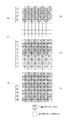
図8に示す、ブラックインクを吐出する第1の記録ヘッド801は、1インチ当たりの吐出口数N=600個の密度で(600dpi)、吐出口数n=30の吐出口(30ノズル)を備えている。本発明の第1の実施形態における記録方法においては、第1の記録ヘッド801に設けられる吐出口n1〜n30のうち、記録の際にインク吐出に使用する吐出口を、図8(1)に示したn19〜n30までの12個、または図8(2)に示したn16〜n27までの12個とする。
尚、図中では、記録ヘッド内部に示す黒丸が記録に使用する吐出口、白丸が記録の際に使用しない吐出口に対応する。
【0054】
また、図8に示したカラーインクを吐出する第2の記録ヘッド802は、1インチ当たりの吐出口数N=600個の密度で(600dpi)、吐出口数n=12個の吐出口(12ノズル)を備えている。本発明の第1の実施形態における記録方法においては、記録ヘッド802に設けられる全吐出口であるn1〜n12までの12個の吐出口を使用して記録を行う。
【0055】
この図8において、記録ヘッド801と記録ヘッド802との吐出口(ノズル)の位置関係は、矢印yで示す副走査方向については、同じ吐出口番号の位置で一致して配列され、矢印xで示す主走査方向については、所定の間隔をおいて配置されている。なお、矢印yは、図中左下に示す矢印(図1において方向を示す矢印と同様の矢印)Yに沿った方向である。また、矢印xについても、図中左下に示す矢印Xに沿った方向である。
【0056】
なお、図8、および以下説明する実施形態においては、カラーインク用の記録ヘッドについて、一つのみ示しているが、記録に用いるカラーインクの数に対応させて、図の矢印x方向に複数のカラーインク用ヘッドを搭載してもよい。本発明は、一般的に用いられるブラック、イエロー、マゼンタ、シアンの4色のインクを吐出して記録を行うインクジェット記録装置に適用可能なものであり、このような構成の場合、図8においては第2の記録ヘッド802を、x方向へ3個備えたものとなる。また、各カラーインクについて、濃度を異ならせたインクを複数用いる場合にはその構成に応じて複数の記録ヘッドを搭載したものとしてもよい。
【0057】
なお、前記ブラックインクを吐出する記録ヘッド801とカラーインクを吐出する記録ヘッド802は、図9に示すように一体の記録ヘッド901として構成されても良い。また、図10や図11に示すように、吐出口の配列を1列ではなく、複数列とした構成としてもよい。この図10の記録ヘッド1001、1002、および図11に示す記録ヘッド1101は、吐出口を2列とし、2列がそれぞれ偶数番目の吐出口に対応した吐出口列(以下、吐出口群ともいう)と奇数番目の吐出口に対応した吐出口列となっており、偶数番目の吐出口と奇数番目の吐出口とが千鳥状に配列された構成となっている。なお、図10に示す構成は、ブラックインク用の記録ヘッド1001と、カラーインク用の記録ヘッド1002とが別体に構成されて分離可能なものであり、また、図11に示す記録ヘッド1101は、ブラックインク用の吐出口列と、カラーインク用の吐出口列とを一体に備えた構成となっている。
【0058】
なお、図9乃至11に図示する内容は、図8に示す内容に対応するものであって、図8と同様に、記録ヘッド内部に示す黒丸が記録に使用する吐出口、白丸が記録の際に使用しない吐出口に対応する。
【0059】
また、このような、図10、図11に示すように吐出口列を構成した記録ヘッドを用いる際の駆動信号は、先行する吐出口群が後追する吐出口群よりもd/v〔秒〕だけ早いタイミングで与えられる。d〔インチ〕は奇数番号と偶数番号の吐出口群の間の距離であり、v〔インチ/秒〕は記録ヘッドの主走査方向への走査速度である。
【0060】
なお、上述した記録ヘッドの構成において、図8の構成においては、第1の記録ヘッド801を第1の吐出口列、第2の記録ヘッド802を第2の吐出口列と称し、801、802を含めて記録手段と称することができる。図9の構成においては、ブラックインク用の吐出口列を第1の吐出口列、カラーインク用の吐出口列を第2の吐出口列とし、記録ヘッド901を記録手段と称することができる。また、図10については、ブラックインク用記録ヘッド1001を第1の吐出口列、カラーインク用記録ヘッド1002を第2の吐出口列と称して、1001と1002を含めて記録を行う構成であることから、記録手段と称することができる。また、図11の構成においては、記録ヘッド1101を記録手段と称して、ブラックインク用の吐出口列を第1の吐出口列、カラーインク用の吐出口列を第2の吐出口列と称することができる。
【0061】
また、使用したブラックインクのブリストウ法におけるKa値は、1.0[ml・m-2・msec-1/2]、カラーインクのブリストウ法におけるKa値は、7.0[ml・m-2・msec-1/2]であり、ブラックインクの方がカラーインクより浸透性が低い特性のため、ブラックインクのKa値は小さい。
【0062】
本発明の第1の実施形態における記録方法を図12、図13を参照して説明する。
【0063】
図12は、互いに補完関係にある3種類の間引きパターンを、吐出口数が3の場合(a1,a2,a3)と、吐出口数が6の場合(b1,b2,b3)について示した図であり、格子状の内部が記録するドットの位置に対応し、また、黒で塗りつぶした位置がインクを吐出してドットを記録する位置であり、塗りつぶされていない位置は、間引かれてドットが記録されない位置である。従って、このような間引きパターンを用いて、記録ドットを示すデータをマスクすることで、パターンの黒で塗られた位置だけがマスクされずに記録されるようデータが変換されることとなる。
【0064】
図12の吐出口数が3の場合に対応したパターンについて見ると、パターンa1、a2、a3を重ねることで、9個のドット位置からなる領域すべてにドットが記録されることとなる。また、吐出口数が6の場合に対応したパターンについても同様となる。
【0065】
また、図13は、記録動作を、記録ヘッドの主走査方向への走査毎に対応させて説明する図である。
【0066】
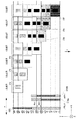
図13の1301a、1301bは、ブラックインク用の記録ヘッドであり、記録ヘッド内の黒丸がインク吐出に使用する吐出口を表している。図13に示す1301aは、図8(1)で示す第1の記録ヘッド801に対応し、n19〜n30までの12の吐出口を使用して記録を行うことを示している。また、図13の1301bは、図8(2)で示す第1の記録ヘッド801に対応し、n16〜n27の12の吐出口を使用して記録を行うことを示している。また、図13の1302は、図8に示すカラーインク用の第2の記録ヘッド802に対応している。このように、本実施形態では、ブラックインク用の第1の記録ヘッドについて、1301aで示すようにn19〜n30の吐出口を使用して記録を行う動作と、1301bで示すようにn16〜n27の吐出口を使用して記録を行う動作とを、適宜行うものである。
【0067】
まず、図13に示す1走査目では、図13のブラックヘッドの1301aにあたる図8(1)に示したブラックインクを吐出可能なn1〜n30の30ノズルの内、吐出に使用するn19〜n30までの12ノズルを用いて記録を行う。その際には、吐出に使用する12ノズルの内の25から30番目までの6ノズルは、図12に示す間引きのパターンb1を用いて、図13のブラックデータのある13aの領域を記録する。
【0068】
続いて、副走査方向に記録媒体を搬送するのに6dot/600dpi分の搬送距離を紙送り用のモータで駆動する。
【0069】
続く2走査目では、図13のブラックヘッドの1301bにあたる図8(2)に示したブラックインクを吐出可能なn1〜n30の30ノズルの内、n16〜n27までの12ノズルを吐出に使用して記録を行う。ここでは、吐出に使用する12ノズルの内の19から24番目までの6ノズルは、図12の間引きパターンb2を用いて、図13のブラックデータのある13aの領域を記録し、25から27番目までの3ノズルは、図12に示すa1の間引きパターンを用いて、図13のブラックデータのある13bの領域を記録する。
【0070】
続いて3dot/600dpi分の記録媒体の搬送を行った後に、続く3走査目では、図13のブラックヘッドの1301bにあたる図8(2)に示したブラックインクを吐出可能なn1〜n30の30ノズルの内、吐出に使用するn16〜n27までの12ノズルで記録が行われる。ここでは、吐出に使用する12ノズルの内の16から21番目までの6ノズルについては、図12の間引きパターンb3を用いて図13のブラックデータのある13aの領域を記録し、22から24番目までの3ノズルは、図12の間引きパターンa2を用いて図13のブラックデータのある13bの領域を記録し、25から27番目までの3ノズルは、図12のa1の間引きパターンを用いて図13のブラックデータのある13cの領域を記録する。
【0071】
さらに、3dot/600dpi分の記録媒体の搬送を行った後の4走査目では、図13のブラックヘッドの1301aにあたる図8(1)に示したブラックインクを吐出可能なn1〜n30の30ノズルの内、n19〜n30までの12ノズルを吐出に使用して記録が行われる。ここでは、12ノズルの内の19から21番目までの3ノズルについては、図12に示すの間引きパターンa3を用いて図13のブラックデータのある13bの領域を記録し、22から24番目までの3ノズルは、図12の間引きパターンa2を用いて図13のブラックデータのある13cの領域を記録し、25から30番目までの6ノズルに関しては、1走査目と同様にして図12の間引きパターンb1を用いて記録を行う。また、この4走査目の記録においては、図13のブラックデータのある13aの領域は既に完成しているため記録はされない。
【0072】
さらに、6dot/600dpi分の記録媒体の搬送を行い、続く5走査目の記録においては、図13のブラックヘッドの1301bにあたる図8(2)に示したブラックインクを吐出可能なn1〜n30の30ノズルの内、n16〜n27までの12ノズルを吐出に使用して記録が行われる。ここでは、その内の16から18番目までの3ノズルについては、図12に示すの間引きパターン(a3)を用いて図13のブラックデータのある13cの領域を記録し、19から27番目までの9ノズルは、2走査目と同様にして各画像領域の記録を行う。また、図13のブラックデータのある13bの領域は、先の走査において記録が既に完成しているためこの走査では記録は行われない。また、この5走査目では図13のカラーヘッドにあたる図8に示したカラーインクを吐出する12ノズルの内の7から12番目までの6ノズルは、図12に示すの間引きパターン(b1)を用いて、図13のカラーデータのある13dの領域を記録する。
【0073】
さらに、3dot/600dpi分の記録媒体の搬送を行い、続く6走査目では、3走査目と同様にしてブラックの各画像領域の記録を行い、図13中のブラックデータのある13cの領域は先の走査において既に記録が完成しているため、この6走査目では記録は行われない。また、この6走査目では図13のカラーヘッドにあたる図8に示したカラーインクを吐出する12ノズルの内の4から9番目までの6ノズルは、図12に示すの間引きパターン(b2)を用いて図13のカラーデータのある13dの領域を記録し、10から12番目までの3ノズルは、図12の間引きパターン(a1)を用いて図13のカラーデータのある13eの領域を記録する。
【0074】
さらに、3dot/600dpi分の記録媒体の搬送を行い、続く7走査目では、ブラックの記録は4走査目と同様にし、カラーの記録は図13のカラーヘッドにあたる図8に示したカラーインクを吐出する12ノズルの内の1から6番目までの6ノズルは、図12の間引きパターン(b3)を用いて図13のカラーデータのある13dの領域を完成し、7から9番目までの3ノズルは、図12の間引きパターン(a2)を用いて図13のカラーデータのある13eの領域を記録し、10から12番目までの3ノズルは、図12の間引きパターン(a1)を用いて図13のカラーデータのある13fの領域を記録する。
【0075】
さらに、6dot/600dpi分の記録媒体の搬送を行い、8走査目(不図示)では、ブラックの記録は5走査目と同様にし、カラーの記録は図13のカラーヘッドにあたる図8に示したカラーインクを吐出する12ノズルの内の1から3番目までの3ノズルは、図12に示す(a3)の間引きパターンを用いて図13のカラーデータのある13eの領域を完成し、4から6番目までの3ノズルは、図12の(a2)の間引きパターンを用いて図13のカラーデータのある13fの領域を記録し、7から12番目までの6ノズルに関しては、5走査目と同様にして図12の(b1)の間引きパターンを用いて記録を行う。
【0076】
さらに、3dot/600dpi分の記録媒体の搬送を行い、9走査目(不図示)では、ブラックの記録は6走査目と同様にし、カラーの記録は図13のカラーヘッドにあたる図8に示したカラーインクを吐出する12ノズルの内の1から3番目までの3ノズルは、図12の(a3)の間引きパターンを用いて図13のカラーデータのある13fの領域を完成し、4から12番目までの9ノズルは、6走査目と同様にして各画像領域の記録を行う。
【0077】
以下、10走査目は7走査目と同様に、11走査目は8走査目と同様に、12走査目は9走査目と同様にして記録を行う。
【0078】
以上のように、ブラックインクを吐出する第1の吐出口列、カラーインクを吐出する第2の吐出口列で画像を完成させる主走査方向への記録走査回数が各々3回で、1主走査毎に副走査方向へ記録媒体を搬送する1回の搬送量を6dot/600dpiと3dot/600dpiの2種類を備えた場合、ブラックインクを吐出する第1の吐出口列で画像を完成させる記録走査回数m=3より、(m+a)=(3+1)=4回[aは1]連続して記録媒体を搬送する搬送量は、(6+3+3+6)dot/600dpiの18dot/600dpiと(3+3+6+3)dot/600dpi又は(3+6+3+3)dot/600dpiの15dot/600dpiの2種類となる。ブラックインクを吐出する第1の吐出口列に対して、カラーインクを吐出する第2の吐出口列の記録媒体を給紙する給紙方向側から使用する吐出口先端部の位置を、図8(1)、図13の1301aのように18dot/600dpiの長さ、図8(2)、図13の1301bのように15dot/600dpiの長さにすることで、マルチパス記録方法で特有の色間(ブラックとカラー間)でのにじみを防止できる上、ブラックインクで完成された画像領域内にカラーインクでの記録を行うまでの時間を常に一定にすることができ、副走査方向への記録走査毎の色ムラを防止する効果もある。
【0079】
なお、本実施形態では、間引きパターンを固定的なパターンとしたが、画像データとの同調性を防止するためにランダムな間引きパターンを用いても、また記録ヘッド毎に異なった間引きパターンでも良い。
【0080】
また、本実施形態では、カラーインクを吐出させる第2の記録ヘッドの吐出口数を12個とし、全吐出口を使用するようにしたが、それ以上の吐出口を備えた記録ヘッドを用いても良い。図14は、カラーインクを吐出する第2の記録ヘッド1402を、ブラックインクを吐出する第1の記録ヘッド1401と同じ吐出口数の記録ヘッドとしたものであり、このような第2の記録ヘッド1402を用いる場合において、第2の記録ヘッド1402のn1〜n12までの12個の吐出口をインク吐出に使用する吐出口とすることで、前述の例と同様の記録を行うことが可能である。
【0081】
また、ブラックインクを吐出させる第1の記録ヘッドも同様に30個の吐出口数を備えていたがそれ以上またはそれ以下の吐出口数を備えて、本マルチパス記録方法で使用する吐出口は本実施形態で使用した12個の位置としても良い。
【0082】
また、本実施形態においては、ブラックインクを吐出する第1の吐出口列に対して、カラーインクを吐出する第2の吐出口列の記録媒体を給紙する給紙方向側から使用する吐出口先端部の位置を、図8(1)、図13の1301aのように18dot/600dpiの長さ、図8(2)、図13の1301bのように15dot/600dpiの長さであったが、この長さに限るものではなく、図15に示す様なブラックインクを吐出させる第一の吐出口列の吐出口数が31個で、(m+a)=(3+1)=4回[aは1]連続して記録媒体を搬送する搬送量の(6+3+3+6)dot/600dpiの18dot/600dpiより大きく(m+a+1)=(3+1+1)=5回[aは1]連続して記録媒体を搬送する搬送量の(6+3+3+6+3)dot/600dpiの21dot/600dpiより小さい図15(A)に示した19dot/600dpiの長さと、(m+a)=(3+1)=4回[aは1]連続して記録媒体を搬送する搬送量の(3+3+6+3)dot/600dpi又は(3+6+3+3)dot/600dpiの15dot/600dpiより大きく(m+a+1)=(3+1+1)=5回[aは1]連続して記録媒体を搬送する搬送量の(3+3+6+3+3)dot/600dpiの18dot/600dpi又は(3+6+3+3+6)dot/600dpiの21dot/600dpiより小さい図15(B)に示した16dot/600dpiの長さにすると、ブラックインクを吐出する第1の記録ヘッドの吐出口n20又n17を使用して完成した画像端部と、カラーインクを吐出させる第2の記録ヘッドの吐出口n12を使用して記録する画像端部が本実施形態よりも1dot/600dpi離れているため、記録走査の境界部分でのブラックとカラーの色間でのにじみを防止するには、より良い効果が得られる。
【0083】
本実施形態において、以上のような制御を行うことにより、マルチパス記録方法における色間のにじみを防止し、更に記録媒体を搬送する搬送量を2種類以上備えた記録方法においても、色ムラを防止した高品位な画像を記録することが可能なインクジェット記録装置を提供できる。
【0084】
(第2の実施形態)
次に、本発明の第2の実施形態について、図を参照して説明する。
【0085】
図16は、本発明の第2の実施形態に係る記録ヘッドを示す図である。図16に示すブラックインクを吐出する第1の記録ヘッド1601は、1インチ当たりN=600個の密度で(600dpi)n=30個の吐出口(30ノズル)を配列したものである。
【0086】
本実施形態で説明する記録方法においては、第1の記録ヘッド1601のインク吐出に使用する吐出口を、図16(1)、図16(2)に示すように、19番目〜30番目の吐出口(n19〜n30)の12個とする。
【0087】
また、同図のカラーインクを吐出する第2の記録ヘッド1602は、1インチ当たりN=600個の密度で(600dpi)n=18個の吐出口(12ノズル)を配列したものである。本実施形態で説明する記録方法においては、第2の記録ヘッド1601に配列される吐出口のうち、図16(1)に黒丸で示すように1番目〜12番目の吐出口(n1〜n12)の12個、または図16(2)に示すように、4番目〜15番目の吐出口(n4〜n15)の12個を使用する。なお、第1の実施形態と同様に、第1の記録ヘッドと第2の記録ヘッドとの吐出口(ノズル)の位置関係は、副走査方向(図中の矢印y)については、同じ吐出口番号の位置で一致して配列され、主走査方向(図中の矢印x)については、所定の間隔をおいて配置されている。また、第1の実施形態と同様に、ブラックインクを吐出する第1の記録ヘッドとカラーインクを吐出する第2の記録ヘッドは、別体として分離された型に限らず、ブラックインク用の吐出口とカラーインク用の吐出口とを一体に有する型の記録ヘッドとして構成されても良い。また、吐出口(ノズル)列についても、図16に示すような1列の構成に限らず、前述したように、千鳥状に吐出口が配列されていても良い。また、カラーインク用の第2の記録ヘッドの吐出口数を、ブラックインク用の第1の記録ヘッドと等しい構成としても良い。また、本実施形態で使用するインクは、第1の実施形態で使用したインクを使用する。
【0088】
次に、本発明の第2の実施形態における記録方法を図12、図17を用いて説明する。
【0089】
図12は、第1の実施形態で説明したように、相互に補完関係にある3種類の間引きパターンについて、吐出口数が3と6の場合のそれぞれに対応したものを示した図である。
【0090】
また、図17は、本実施形態における記録動作を、記録ヘッドの主走査方向への走査毎に対応させて説明する図である。図17の1701は、図16に示すブラックインク用の記録ヘッド1601に対応し、記録ヘッド内の黒丸がインク吐出に使用する吐出口を表している。また、図17の1702a、1702bは、カラーインク用の記録ヘッド(図16のカラーインク用記録ヘッド1602に対応)であり、1702aは、図16(1)で示す第2の記録ヘッド1602に対応し、n1〜n12までの12の吐出口を使用して記録を行うことを示している。また、図17の1702bは、図16(2)で示す第2の記録ヘッド1602に対応し、n4〜n15の12の吐出口を使用して記録を行うことを示している。このように、本実施形態では、カラーインク用の第2の記録ヘッドについて、1702aで示すようにn1〜n12の吐出口を使用して記録を行う動作と、1702bで示すようにn4〜n15の吐出口を使用して記録を行う動作とを、適宜行うものである。
【0091】
まず、図17に示す1走査目では、ブラックインク用の第1の記録ヘッド1701(図16に示す記録ヘッド1601に対応)に設けられるn1〜n30の30ノズルの内、n19〜n30までの12ノズルを吐出に使用して記録を行う。
この記録においては、その内の25から30番目(n25〜n30)までの6ノズルについては、図12の(b1)の間引きパターンを用い、図17に示す、ブラックデータのある17aの領域を記録する。
【0092】
続いて、副走査方向に記録媒体を搬送するのに3dot/600dpi分の搬送距離を紙送り用のモータで駆動する。
【0093】
続いて行う2走査目の記録においては、1走査目と同様にブラックインク用の第1の記録ヘッド1701のn19〜n30までの12ノズルを吐出に使用して記録を行う。この記録においては、12ノズルの内の22から27番目(n22〜n27)までの6ノズルについては、図12の(b2)の間引きパターンを用いて、図17に示されるブラックデータのある17aの領域を記録し、また、n28〜n30までの3ノズルについては、図12の(a1)の間引きパターンを用いて、図17に示されるブラックデータのある17bの領域を記録する。
【0094】
続いて3dot/600dpi分の記録媒体の搬送を行い、続く3走査目の記録では、ブラックインク用の第1の記録ヘッドのn19〜n30までの12ノズルを吐出に使用して記録を行う。この記録においては、12ノズルの内のn19〜n24までの6ノズルについては、図12の(b3)の間引きパターンを用いて図17に示されるブラックデータのある17aの領域を記録し、n25〜n27までの3ノズルについては、図12の(a2)の間引きパターンを用いて図17に示されるブラックデータのある17bの領域を記録し、さらに、n28〜n30までの3ノズルについては、図12の(a1)の間引きパターンを用い、図17に示されるブラックデータのある17cの領域を記録する。
【0095】
さらに、6dot/600dpi分の記録媒体の搬送を行い、続いて行う4走査目の記録では、ブラックインク用の記録ヘッド1701については、先の走査と同様に、n19〜n30までの12ノズルを吐出に使用して記録を行い、この4走査目の記録においては、12ノズルの内のn19〜n21までの3ノズルについては、図12の(a3)の間引きパターンを用い、図17に示されるブラックデータのある17bの領域を記録し、n22〜n24までの3ノズルについては、図12の(a2)の間引きパターンを用いて図17に示されるブラックデータのある17cの領域を記録し、n25〜n30までの6ノズルについては、1走査目と同様にして図12の(b1)の間引きパターンを用いて記録を行う。また、図17のブラックデータのある17aの領域は先の走査において既に完成しているため、この4走査目においては記録は行われない。
【0096】
さらに、3dot/600dpi分の記録媒体の搬送を行った後の5走査目の記録では、ブラックインク用の第1の記録ヘッド1701のn19〜n30までの12ノズルを吐出に使用し、その内のn19〜n21までの3ノズルについては、図12の(a3)の間引きパターンを用い、図17のブラックデータのある17cの領域を記録し、n22〜n30までの9ノズルは、2走査目と同様にして各画像領域の記録を行う。また、図17に示されるブラックデータのある17bの領域は既に完成しているため、この5走査目においては記録は行われない。
また、この5走査目では、カラーインク用の第2の記録ヘッド1702bに対応する図16(2)に示した記録ヘッド1602のn1〜n15の15ノズルの内、n4〜n15までの12ノズルを吐出に使用して記録を行う。このカラーインク用の記録ヘッドによる記録においては、12ノズルの内のn10〜n15までの6ノズルについては、図12の(b1)の間引きパターンを用いて、図17のカラーデータのある17dの領域を記録する。
【0097】
さらに、3dot/600dpi分の記録媒体の搬送を行った後の6走査目の記録においては、ブラックインク用の第1の記録ヘッド1701については、先に説明した3走査目と同様にしてブラックの各画像領域の記録を行う。ここで、図17のブラックデータのある17cの領域は、先の走査で既に完成しているため、この6走査目においては記録は行われない。また、この6走査目では、カラーインク用の第2の記録ヘッド1702について、図16(2)の1602に示した用に、n1〜n15の15ノズルの内、n4〜n15までの12ノズルを吐出に使用して記録を行う(図17の1702b)。このカラーインク用の記録ヘッドによる記録においては、吐出に使用するノズルの内のn7〜n12までの6ノズルについては、図12の(b2)の間引きパターンを用いて、図17のカラーデータのある17dの領域を記録し、また、n13〜n15までの3ノズルについては、図12の(a1)の間引きパターンを用い、図17のカラーデータのある17eの領域を記録する。
【0098】
さらに、6dot/600dpi分の記録媒体の搬送を行った後の7走査目の記録において、ブラックの記録は4走査目と同様にし、カラーインク用の記録ヘッドによる記録は、図17の1702a、図16(1)の1602で示すようにn1〜n15の15ノズルの内、n1〜n12までの12ノズルを吐出に使用して記録を行う。このカラーインク用の記録ヘッドによる記録においては、吐出に使用する12ノズルの内のn1〜n6までの6ノズルについては図12の(b3)の間引きパターンを用い、図17のカラーデータのある17dの領域を完成させるよう記録し、n7〜n9までの3ノズルについては図12の(a2)の間引きパターンを用いることで図17のカラーデータのある17eの領域を記録し、また、n10〜n12までの3ノズルについては図12の(a1)の間引きパターンを用いて図17のカラーデータのある17fの領域を記録する。
【0099】
さらに、6dot/600dpi分の記録媒体の搬送を行い、続く8走査目の記録(不図示)では、ブラックの記録は5走査目と同様にし、カラーの記録は図17の1702b、図16(2)の1602で示すようにn1〜n15の15ノズルの内、n4〜n15までの12ノズルを吐出に使用して記録を行う。この8走査目のカラーインクによる記録において、吐出に使用する12ノズルの内のn4〜n6までの3ノズルについては図12の(a3)の間引きパターンを用いて、図17のカラーデータのある17eの領域を完成させるよう記録し、n7〜n9までの3ノズルについては図12の(a2)の間引きパターンを用いて図17のカラーデータのある17fの領域を記録し、n10〜n15までの6ノズルに関しては、5走査目と同様にして図12の(b1)の間引きパターンを用いて記録を行う。
【0100】
さらに、3dot/600dpi分の記録媒体の搬送を行い、続く9走査目の記録(不図示)では、ブラックの記録は6走査目と同様にし、また、カラーの記録については図17の1702b、図16(2)の1602で示すように、n4〜n15までの12ノズルを吐出に使用して記録を行う。この9走査目におけるカラーインク用記録ヘッドによる記録では、吐出に使用する12ノズルの内のn4〜n6までの3ノズルについては、図12の(a3)の間引きパターンを用いて図17のカラーデータのある17fの領域を完成させるよう記録し、また、n7〜n15までの9ノズルは、6走査目と同様にして各画像領域の記録を行う。
【0101】
以下、10走査目は7走査目と同様に、11走査目は8走査目と同様に、12走査目は9走査目と同様にして記録を行う。
【0102】
以上のように、ブラックインクを吐出する第1の吐出口列、カラーインクを吐出する第2の吐出口列で画像を完成させる主走査方向への記録走査回数が各々3回で、1主走査毎に副走査方向へ記録媒体を搬送する1回の搬送量を6dot/600dpiと3dot/600dpiの2種類を備えた場合、ブラックインクを吐出する第1の吐出口列で画像を完成させる記録走査回数m=3より、(m+a)=(3+1)=4回[aは1]連続して記録媒体を搬送する搬送量は、(6+3+3+6)dot/600dpiの18dot/600dpiと(3+6+3+3)dot/600dpi又は(3+3+6+3)dot/600dpiの15dot/600dpiの2種類となる。ブラックインクを吐出する第1の吐出口列に対して、カラーインクを吐出する第2の吐出口列の記録媒体を給紙する給紙方向側から使用する吐出口先端部の位置を、図16(1)、図17の1702aのように18dot/600dpiの長さ、図16(2)、図17の1702bのように15dot/600dpiの長さにすることで、マルチパス記録方法で特有の色間(ブラックとカラー間)でのにじみを防止できる上、ブラックインクで完成された画像領域内にカラーインクでの記録を行うまでの時間を常に一定にすることができ、副走査方向への記録走査毎の色ムラを防止する効果もある。
【0103】
なお、本実施形態では、間引きパターンを固定的なパターンとしたが、画像データとの同調性を防止するためにランダムな間引きパターンを用いても、また記録ヘッド毎に異なった間引きパターンでも良い。また、本実施形態では、カラーインクを吐出させる第2の記録ヘッドの吐出口数が15個であったが、それ以上でも良く、図14に示すようにカラーインクを吐出する第2の記録ヘッドを第1の記録ヘッドと同じ吐出口数のヘッドを使用し、本マルチパス記録方法でインク吐出に使用する吐出口をn1〜n12とn4〜n15までの12個の吐出口としても良い。また、ブラックインクを吐出させる第1の記録ヘッドも同様に30個の吐出口数を備えていたがそれ以上またはそれ以下の吐出口数を備えて、本マルチパス記録方法で使用する吐出口は本実施形態で使用した12個の位置としても良い。
【0104】
また、本実施形態においては、ブラックインクを吐出する第1の吐出口列に対して、カラーインクを吐出する第2の吐出口列の記録媒体を給紙する給紙方向側から使用する吐出口先端部の位置を、図16(1)、図17の1702aのように18dot/600dpiの長さ、図16(2)、図17の1702bのように15dot/600dpiの長さであったが、この長さに限るものではなく、図18に示す様なブラックインクを吐出させる第一の吐出口列の吐出口数が31個で、(m+a)=(3+1)=4回[aは1]連続して記録媒体を搬送する搬送量の(6+3+3+6)dot/600dpiの18dot/600dpiより大きく(m+a+1)=(3+1+1)=5回[aは1]連続して記録媒体を搬送する搬送量の(6+3+3+6+3)dot/600dpiの21dot/600dpiより小さい図18(A)に示した19dot/600dpiの長さと、(m+a)=(3+1)=4回[aは1]連続して記録媒体を搬送する搬送量の(3+3+6+3)dot/600dpi又は(3+6+3+3)dot/600dpiの15dot/600dpiより大きく(m+a+1)=(3+1+1)=5回[aは1]連続して記録媒体を搬送する搬送量の(3+3+6+3+3)dot/600dpiの18dot/600dpi又は(3+6+3+3+6)dot/600dpi=21dot/600dpiより小さい図18(B)に示した16dot/600dpiの長さにすると、ブラックインクを吐出する第1の記録ヘッドの吐出口n20を使用して完成した画像端部と、カラーインクを吐出させる第2の記録ヘッドの吐出口n12又はn15を使用して記録する画像端部が本実施形態よりも1dot/600dpi離れているため、記録走査の境界部分でのブラックとカラーの色間でのにじみを防止するには、より良い効果が得られる。
【0105】
本実施形態において、以上のような制御を行うことにより、マルチパス記録方法における色間のにじみを防止し、更に記録媒体を搬送する搬送量を2種類以上備えた記録方法においても、色ムラを防止した高品位な画像を記録することが可能なインクジェット記録装置を提供できる。
【0106】
(第3の実施形態)
図19は、本発明の第3の実施形態に係る記録ヘッドと、記録に使用する吐出口を示す概略図である。
【0107】
図19の1901はブラックインク用の第1の記録ヘッドであり、先の実施形態において説明した図8の記録ヘッド801と同様に1インチ当たりN=600個の密度で(600dpi)n=30個の吐出口(30ノズル)を有している。
本実施形態においては、図19(1)の1901に示すようにインク吐出に使用する吐出口をn25〜n30までの6個、または図19(2)の1901に示すようにn25〜n27までの3個として記録を行う。
【0108】
また、図19の1902は、カラーインク用の第2の記録ヘッドであり、第1の実施形態おいて図8に示した記録ヘッドと同様に1インチ当たりN=600個の密度で(600dpi)n=12個の吐出口(12ノズル)を有している。この第2の記録ヘッド1902について、本実施形態における記録方法では、n1〜n12までの12個の全吐出口を使用して記録を行う。
【0109】
また、各記録ヘッド間の吐出口(ノズル)の位置関係については、先の実施形態と同様であり、副走査方向については、同じ吐出口番号の位置で一致して配列され、主走査方向については、所定の間隔をおいて配置されている。尚、前記ブラックインクを吐出する記録ヘッドとカラーインクを吐出する記録ヘッドは、第1の実施形態で説明したように、ブラックインク用とカラーインク用とを別体とした分離型でなく、一体型の記録ヘッドとして構成されても良く、また吐出口(ノズル)列が1列でなく千鳥状に配列されていても良い。また、第2の記録ヘッドの吐出口数が第1の記録ヘッドと等しい構成でも良い。また、本実施形態で使用するインクは、第1の実施形態で使用したインクを使用する。
【0110】
次に、本発明の第3の実施形態における記録方法を図12、図20を参照して説明する。
【0111】
図12は、先の実施形態において詳述したように相互に補完関係にある3種類の間引きパターンを示す図である。
【0112】
また、図20は、記録動作を、記録ヘッドの主走査方向への走査毎に対応させて説明する図である。
【0113】
図20の2001a、2001bは、ブラックインク用の第1の記録ヘッドであり、同じブラックインク用の記録ヘッドについて、吐出に使用する吐出口を異ならせた状態を表したものである。また、2002は、カラーインク用の第2の記録ヘッドである。この図20において、記録ヘッド内の黒丸がインク吐出に使用する吐出口を表している。
【0114】
図20に示す2001aは、図19(1)で示す第1の記録ヘッド1901に対応し、n1〜n30の吐出口のうち、n25〜n30までの6の吐出口を使用して記録を行うことを表している。また、図20の2001bは、図19(2)で示す第1の記録ヘッド1901に対応し、n25〜n27の3個の吐出口を使用して記録を行うことを表している。また、2002は、図19(1)、(2)に示すカラーインク用の第2の記録ヘッド1902に対応している。
【0115】
このように、本実施形態では、ブラックインク用の第1の記録ヘッドについて、2001aで示すようにn25〜n30の吐出口を使用して記録を行う動作と、2001bで示すようにn25〜n27の吐出口を使用して記録を行う動作とを、適宜行うものである。
【0116】
以下、記録動作について、図20を参照し、記録走査の順に従って詳細に説明する。
【0117】
まず、1走査目では、図20の2001aに示すように、ブラックインク用記録ヘッドのn1〜n30の30ノズルの内、n25〜n30までの6ノズルを吐出に使用し、図20に示されるブラックデータのある領域20aを、1パス記録方法で記録する。尚、ここで1パス記録方法とは、図12に示すような間引きのパターンを用いずに記録を行うことで、1回の主走査により対応する領域の画像を完成させる記録方法である。
【0118】
続いて、副走査方向に記録媒体を搬送するのに6dot/600dpi分の搬送距離を紙送り用のモータで駆動する。その後、続く2走査目の記録においては、図20に示されるブラックデータのある領域20aは1走査目の記録で既に完成させており、図20の2001bで示すように、ブラックインク用記録ヘッドのn25〜n27までの3ノズルを用い、図20のブラックデータのある領域20bを、1パス記録方法で記録する。
【0119】
続いて、3dot/600dpi分記録媒体の搬送を行い、続く3走査目の記録を行う。この3走査目の記録の際には、図20に示されるブラックデータのある領域20a、20bそれぞれは、先の1走査目と2走査目の記録において既に完成させている。従って、この3走査目の記録においては、先の走査と同様に、図20の2001bで示すようにブラックインク用記録ヘッドのn25〜n27までの3ノズルを用い、図20に示されるブラックデータの領域20cを1パス記録方法で記録する。
【0120】
さらに、前回同様に3dot/600dpi分記録媒体の搬送を行った後の4走査目の記録を行う。この4走査目の記録に先立って、図20に示されるブラックデータがある領域20a、20b、20cについては既に完成させている。4走査目の記録においては、ブラックインク用記録ヘッドによる記録は、1走査目と同様に行う。
【0121】
さらに、6dot/600dpi分の記録媒体の搬送を行った後の5走査目の記録においては、ブラックインク用記録ヘッドによる記録は2走査目と同様とする。また、カラーインク用記録ヘッド2002(図19に示す第2の記録ヘッド1902に対応)による記録は、全12ノズルの内のn7〜n12までの6ノズルにより、図12の(b1)の間引きパターンを用い、図20に示されるカラーデータが存在する領域20dを記録する。
【0122】
さらに、3dot/600dpi分の記録媒体の搬送を行った後の6走査目の記録においては、ブラックインク用記録ヘッドによる記録は3走査目と同様とする。また、カラーインク用記録ヘッド2002による記録は、全12ノズルの内のn4〜n9までの6ノズルにより、図12の(b2)の間引きパターンを用い、図20のカラーデータの存在する領域20dを記録し、また、n10〜n12までの3ノズルにより、図12の(a1)の間引きパターンを用いて図20に示すカラーデータの存在する領域20eを記録する。
【0123】
さらに、3dot/600dpi分の記録媒体の搬送を行った後の7走査目の記録においては、ブラックインク用記録ヘッドによる4走査目と同様とする。また、カラーインク用記録ヘッド2002による記録は、全12ノズルの内のn1〜n6までの6ノズルにより、図12の(b3)の間引きパターンを用い、図20のカラーデータの存在する領域20dを完成させるよう記録するとともに、n7〜n9までの3ノズルにより図12の(a2)の間引きパターンを用い、図20のカラーデータの存在する領域20eを記録し、n10〜n12までの3ノズルにより図12の(a1)の間引きパターンを用いて図20に示されるカラーデータの存在する領域20fを記録する。
【0124】
さらに、6dot/600dpi分の記録媒体の搬送を行った後の8走査目(不図示)の記録においては、ブラックインク用記録ヘッドによる記録は5走査目と同様とする。また、カラーインク用記録ヘッド2002によるカラー記録は、全12ノズルの内のn1〜n3までの3ノズルにより図12の(a3)の間引きパターンを用い、図20に示されるカラーデータの存在する領域17eを完成させるよう記録し、n4〜n6までの3ノズルにより図12の(a2)の間引きパターンを用いて図20のカラーデータの存在する領域17fを記録し、また、n7〜n12までの6ノズルについては5走査目の記録と同様にして図12の(b1)の間引きパターンを用いて記録を行う。
【0125】
さらに、3dot/600dpi分の記録媒体の搬送を行い、続く9走査目(不図示)の記録においては、ブラックインク用記録ヘッドによる記録は6走査目と同様とする。また、カラーインク用記録ヘッド2002による記録については、全12ノズルの内のn1〜n3までの3ノズルにより図12の(a3)の間引きパターンを用いて図20に示されるカラーデータのある領域17fを完成させるよう記録し、n4〜n12までの9ノズルについては6走査目と同様にして各画像領域の記録を行う。
【0126】
以下、10走査目は7走査目と同様に、11走査目は8走査目と同様に、12走査目は9走査目と同様にして記録を行う。
【0127】
以上説明した本実施形態の記録方法は、ブラックインクを吐出する第1の記録ヘッドの吐出口列で画像を完成させる主走査方向への記録走査回数を1回、カラーインクを吐出する第2の吐出口列で画像を完成させる主走査方向への記録走査回数が3回であり、ブラックとカラーとで回数が異なる。この記録方法において、1主走査毎に副走査方向へ記録媒体を搬送する1回の搬送量を6dot/600dpiと3dot/600dpiの2種類を備えた場合、ブラックインクを吐出する第1の吐出口列で画像を完成させる記録走査回数m=1より、(m+a)=(1+3)=4回[aは3]連続して記録媒体を搬送する搬送量は、(6+3+3+6)dot/600dpiの18dot/600dpiと(3+3+6+3)dot/600dpi又は(3+6+3+3)dot/600dpiの15dot/600dpiの2種類となる。ブラックインクを吐出する第1の吐出口列に対して、カラーインクを吐出する第2の吐出口列の記録媒体を給紙する給紙方向側から使用する吐出口先端部の位置を、図19(1)、図20の2001aの様に18dot/600dpiの長さ、図19(2)、図20の2001bの様に15dot/600dpiの長さにする本発明を利用して、カラーインクを吐出する第2の記録ヘッドが3回の記録走査で画像を完成させるマルチパス記録方法でブラックインクを吐出する第1の記録ヘッドが1回の記録走査で画像を完成させる1パス記録方法の組み合わせにおいても、マルチパス記録方法で特有の色間(ブラックとカラー間)でのにじみを防止できる上、ブラックインクで完成された画像領域内にカラーインクでの記録を行うまでの時間を常に一定にすることができ、副走査方向への記録走査毎の色ムラを防止する効果もある。
【0128】
なお、本実施形態では、間引きパターンを固定的なパターンとしたが、画像データとの同調性を防止するためにランダムな間引きパターンを用いても、また記録ヘッド毎に異なった間引きパターンでも良い。また、本実施形態では、カラーインクを吐出させる第2の記録ヘッドの吐出口数が12個とし全吐出口を使用するようにしたが、それ以上でも良く、図14に示すようにカラーインクを吐出する第2の記録ヘッドを第1の記録ヘッドと同じ吐出口数のヘッドを使用し、本マルチパス記録方法でインク吐出に使用する吐出口をn1〜n12までの12個の吐出口としても良い。また、ブラックインクを吐出させる第1の記録ヘッドも同様に30個の吐出口数を備えていたがそれ以上またはそれ以下の吐出口数を備えて、本マルチパス記録方法で使用する吐出口は本実施形態で使用した6個又は3個の位置としても良い。
【0129】
また、本実施形態においては、ブラックインクを吐出する第1の吐出口列に対して、カラーインクを吐出する第2の吐出口列の記録媒体を給紙する給紙方向側から使用する吐出口先端部の位置を、図19(1)、図20に示す2001aの様に18dot/600dpiの長さ、図19(2)、図20に示す2001bの様に15dot/600dpiの長さであったが、この長さに限るものではなく、図21に示す様なブラックインクを吐出させる第一の吐出口列の吐出口数が31個で、(m+a)=(1+3)=4回[aは3]連続して記録媒体を搬送する搬送量の(6+3+3+6)dot/600dpiの18dot/600dpiより大きく(m+a+1)=(1+3+1)=5回[aは3]連続して記録媒体を搬送する搬送量の(6+3+3+6+3)dot/600dpiの21dot/600dpiより小さい図21(A)に示した19dot/600dpiの長さと、(m+a)=(1+3)=4回[aは3]連続して記録媒体を搬送する搬送量の(3+3+6+3)dot/600dpi又は(3+6+3+3+)dot/600dpiの15dot/600dpiより大きく(m+a+1)=(1+3+1)=5回[aは3]連続して記録媒体を搬送する搬送量の(3+3+6+3+3)dot/600dpiの18dot/600dpi又は(3+6+3+3+6)dot/600dpiの21dot/600dpiより小さい図21(B)に示した16dot/600dpiの長さにすると、ブラックインクを吐出する第1の記録ヘッドの吐出口n26を使用して完成した画像端部と、カラーインクを吐出させる第2の記録ヘッドの吐出口n12を使用して記録する画像端部が本実施形態よりも1dot/600dpi離れているため、記録走査の境界部分でのブラックとカラーの色間でのにじみを防止するには、より良い効果が得られる。
【0130】
本実施形態において、以上のような制御を行うことにより、1パス記録方法と3パス記録方法の様にマルチパス数が異なった組み合わせにおいても色間のにじみを防止し、更に記録媒体を搬送する搬送量を2種類以上備えた記録方法においても、色ムラを防止した高品位な画像を記録することが可能なインクジェット記録装置を提供できる。
【0131】
(第4の実施形態)
次に、本発明の第4の実施形態について、図を参照して詳細に説明する。
【0132】
図22は、本発明の第4の実施形態に係る記録ヘッドの配置と、記録の際にインク吐出に使用するノズルを示す概略図であり、先に説明した他の図と同様に、黒丸がインク吐出に使用するノズルを示している。
【0133】
図22(1)および(2)に示すブラックインクを吐出する第1の記録ヘッド2201は、1インチ当たりN=600個の密度で(600dpi)n=30個の吐出口(30ノズル)を有している。本実施形態における記録方法においては、インク吐出に使用する吐出口を図22(1)の2201に示したn1〜n6までの6個、または図22(2)の2201に示したn4〜n6までの3個とし、記録動作において、適宜使い分けている。
【0134】
また、図22に示したカラーインクを吐出する第2の記録ヘッド2202は、1インチ当たりN=600個の密度で(600dpi)n=12個の吐出口(12ノズル)を有している。本実施形態における記録方法においては、カラーインク用の第2の記録ヘッド2202のn1〜n12までの12個の全吐出口を使用して記録を行う。また、各記録ヘッド間の吐出口(ノズル)の位置関係は、副走査方向については、ブラックインクを吐出する記録ヘッドのn19〜n30の吐出口番号がカラーインクを吐出する記録ヘッドのn1〜n12の位置で一致して配列され、主走査方向については、所定の間隔をおいて配置されている。尚、前記ブラックインクを吐出する記録ヘッドとカラーインクを吐出する記録ヘッドは、第1の実施形態で説明した様に、分離型でなく一体型の記録ヘッドとして構成されても良く、また吐出口(ノズル)列が1列でなく千鳥状に配列されていても良く、また第2の記録ヘッドの吐出口数が第1の記録ヘッドと等しい構成でも良い。また、本実施形態で使用するインクは、第1の実施形態で使用したインクを使用する。
【0135】
本発明の第4の実施形態における記録方法を図12、図23を用いて説明する。図12は、前述のように、相互に補完関係にある3種類の間引きパターンを示した図である。
【0136】
また、図23の2301a、2301bは、ブラックインク用の記録ヘッドであり、前述のように記録ヘッド内の黒丸がインク吐出に使用する吐出口を表している。図23に示す2301aは、図22(1)で示す第1の記録ヘッド2201に対応し、n1〜〜n6までの6個の吐出口を使用して記録を行うことを示している。また、図23の2301bは、図22(2)で示す第1の記録ヘッド2201に対応し、n4〜n6の3個の吐出口を使用して記録を行うことを示している。また、図23の2302は、図22に示すカラーインク用の第2の記録ヘッド2202に対応している。このように、本実施形態では、ブラックインク用の第1の記録ヘッド2201(図22)について、図23に2301aで示すようにn1〜n6の吐出口を使用して記録を行う動作と、図23に2301bで示すようにn4〜n6の吐出口を使用して記録を行う動作とを、適宜行うものである。
【0137】
まず、図23に示す1走査目の記録において、カラーインクを吐出する記録ヘッド2302の吐出に使用する12ノズルの内のn7〜n12までの6ノズルにより、図12の(b1)の間引きパターンを用いて、図23に示されるカラーデータのある領域23aを記録する。
【0138】
続いて、副走査方向に記録媒体を搬送するのに3dot/600dpi分の搬送距離を紙送り用のモータで駆動する。
【0139】
この搬送動作に続いて行う2走査目の記録においては、カラーインクを吐出する記録ヘッド2302の12ノズルの内のn4〜n9までの6ノズルにより、図12の(b2)の間引きパターンを用いて図23に示されるカラーデータの存在する領域23aを記録し、また、n10〜n12までの3ノズルについては図12の(a1)の間引きパターンを用い、図23のカラーデータのある領域23bを記録する。
【0140】
さらに、3dot/600dpi分記録媒体の搬送を行った後の3走査目の記録においては、カラーインク用の記録ヘッド2302の全12ノズルの内のn1〜n6までの6ノズルにより、図12の(b3)の間引きパターンを用い図23に示されるカラーデータの領域23aを記録し、また、n7〜n9までの3ノズルについては図12の(a2)の間引きパターンを用いて図23の領域23bを記録し、また、n10〜n12までの3ノズルについては図12の(a1)の間引きパターンを用いて図23のカラーデータのある領域23cを記録する。
【0141】
さらに、6dot/600dpi分記録媒体の搬送を行った後の4走査目の記録では、カラーインク用の第2の記録ヘッド2302の全12ノズルの内のn1〜n3までの3ノズルにより、図12の(a3)の間引きパターンを用いて、図23のカラーデータの存在する領域23bを記録し、n4〜n6までの3ノズルについて図12の(a2)の間引きパターンを用い、図23のカラーデータのある領域23cを記録し、n7〜n12番目までの6ノズルについては、1走査目と同様に図12の(b1)の間引きパターンを用いて対応する領域の記録を行う。また、図23のカラーデータのある領域23aは既に記録が完成しているため本記録走査においては記録は行われない。
【0142】
さらに、3dot/600dpi分記録媒体の搬送を行った後の5走査目の記録においては、カラーインク用の第2の記録ヘッド2302の全12ノズルの内のn1〜n3までの3ノズルにより図12の(a3)の間引きパターンを用いて図23のカラーデータ領域23cを記録し、n4〜n12までの9ノズルについては2走査目と同様にして各ノズルが対応する画像領域の記録を行う。また、図23のカラーデータ領域23bについては先の走査において既に完成しているため、本記録走査においては記録は行われない。
【0143】
さらに、3dot/600dpi分記録媒体の搬送を行った後の6走査目の記録においては、カラーインク用第2の記録ヘッド2302による記録は3走査目の記録と同様に行う。なお、図23に示されるカラーデータ領域23cについては先の走査で記録が完成している。
【0144】
さらに、6dot/600dpi分記録媒体の搬送を行った後の7走査目の記録においては、カラーインク用第2の記録ヘッド2302による記録は4走査目と同様とする。また、ブラックインク用の第1の記録ヘッドによる記録は、n1〜n30の30ノズルの内、n1〜n6までの6個のノズルを用い、図23に示されるブラックデータの領域23dに対し、1パス記録方法により行われる。この走査の記録において、ブラックインク用の第2の記録ヘッドの使用する吐出口については、図23の2301a、図22(1)の2201で示している。
【0145】
さらに、3dot/600dpi分記録媒体の搬送を行った後の8走査目(不図示)の記録では、カラーの記録は5走査目と同様とする。また、この走査の時点で、図23のブラックデータのある領域23dは先の記録走査において既に完成されている。従って、ブラックインク用の第2の記録ヘッドによる記録については、図23に2301b、図22(2)の記録ヘッド2201に示すように、ブラックインクを吐出するn1〜n30の30ノズルの内、n4〜n6までの3ノズルにより、図23のブラックデータのある領域23eを1パス記録方法で記録する。
【0146】
さらに、3dot/600dpi分記録媒体の搬送を行った後の9走査目(不図示)の記録においては、カラーの記録は6走査目と同様とする。なお、この記録走査の時点で図23に示されるブラックデータの領域23eに対する記録は既に完成されている。従って、ブラックインク用の記録ヘッドによる記録は、図23に示す2301b、図22(2)の記録ヘッド2201に示すように、全30ノズルの内のn4〜n6までの3ノズルを用いて、図23に示されるブラックデータ領域23fを1パス記録方法で行う。
【0147】
以下、10走査目は7走査目と同様に、11走査目は8走査目と同様に、12走査目は9走査目と同様にして記録を行う。
【0148】
以上のように、ブラックインクを吐出する第1の吐出口列で画像を完成させる主走査方向への記録走査回数が1回、カラーインクを吐出する第2の吐出口列で画像を完成させる主走査方向への記録走査回数が3回と異なり、1主走査毎に副走査方向へ記録媒体を搬送する1回の搬送量を6dot/600dpiと3dot/600dpiの2種類を備えた場合、ブラックインクを吐出する第1の吐出口列で画像を完成させる記録走査回数m=1より、(m+a)=(1+3)=4回[aは3]連続して記録媒体を搬送する搬送量は、(6+3+3+6)dot/600dpiの18dot/600dpiと(3+3+6+3)dot/600dpi又は(3+6+3+3)dot/600dpiの15dot/600dpiの2種類となる。そして、ブラックインクを吐出する第1の吐出口列に対して、カラーインクを吐出する第2の吐出口列の記録媒体を排紙する排紙方向側から使用する吐出口先端部の位置を、図22(1)、図23の2301aのように18dot/600dpiの長さ、図22(2)、図23の2301bのように15dot/600dpiの長さにする本発明を利用して、カラーインクを吐出する第2の記録ヘッドによるマルチパス記録方法で画像を完成させた後、ブラックインクを吐出する第1の記録ヘッドで画像を完成させる場合においても、マルチパス記録方法で特有の色間(ブラックとカラー間)でのにじみを防止できる上、ブラックインクで完成された画像領域内にカラーインクでの記録を行うまでの時間を常に一定にすることができ、副走査方向への記録走査毎の色ムラを防止する効果もある。
【0149】
なお、本実施形態では、間引きパターンを固定的なパターンとしたが、画像データとの同調性を防止するためにランダムな間引きパターンを用いても、また記録ヘッド毎に異なった間引きパターンでも良い。また、本実施形態では、カラーインクを吐出させる第2の記録ヘッドの吐出口数が12個とし全吐出口を使用するようにしたが、それ以上でも良く、図14に示すようなカラーインクを吐出する第2の記録ヘッドを第1の記録ヘッドと同じ吐出口数のヘッドを使用し、本マルチパス記録方法でインク吐出に使用する吐出口をn19〜n30までの12個の吐出口としても良い。また、ブラックインクを吐出させる第1の記録ヘッドについても30個の吐出口数を備えていたがそれ以上またはそれ以下の吐出口数を備えて、本マルチパス記録方法で使用する吐出口は本実施形態で使用したn1〜n6までの6個又はn4〜n6までの3個の位置としても良い。
【0150】
また、本実施形態においては、ブラックインクを吐出する第1の吐出口列に対して、カラーインクを吐出する第2の吐出口列の記録媒体を排紙する排紙方向側から使用する吐出口先端部の位置を、図22(1)、図23の2301aのように18dot/600dpiの長さ、図22(2)、図23の2301bのように15dot/600dpiの長さであったが、この長さに限るものではなく、図24に示す様なブラックインクを吐出させる第一の吐出口列の吐出口数が31個で、(m+a)=(1+3)=4回[aは3]連続して記録媒体を搬送する搬送量の(6+3+3+6+3)dot/600dpiの18dot/600dpiより大きく(m+a+1)=(1+3+1)=5回[aは3]連続して記録媒体を搬送する搬送量の(6+3+3+6+3)dot/600dpiの21dot/600dpiより小さい図24(1)に示した19dot/600dpiの長さと、(m+a)=(1+3)=4回[aは3]連続して記録媒体を搬送する搬送量の(3+3+6+3)dot/600dpi又は(3+6+3+3)dot/600dpiの15dot/600dpiより大きく(m+a+1)=(1+3+1)=5回[aは3]連続して記録媒体を搬送する搬送量の(3+3+6+3+3)dot/600dpiの18dot/600dpi又は(3+6+3+3+6)dot/600dpiの21dot/600dpiより小さい図24(2)に示した16dot/600dpiの長さにすると、ブラックインクを吐出する第1の記録ヘッドの吐出口n26を使用して完成した画像端部と、カラーインクを吐出させる第2の記録ヘッドの吐出口n12を使用して記録する画像端部が本実施形態よりも1dot/600dpi離れているため、記録走査の境界部分でのブラックとカラーの色間でのにじみを防止するには、より良い効果が得られる。
【0151】
本実施形態において、以上のような制御を行うことにより、第2の記録ヘッドで先に画像を完成させた後、第1の記録ヘッドで画像を完成させる場合においてもマルチパス記録方法で特有の色間のにじみを防止し、更に記録媒体を搬送する搬送量を2種類以上備えた記録方法においても、色ムラを防止した高品位な画像を記録することが可能なインクジェット記録装置を提供できる。
【0152】
【発明の効果】
以上説明したように本発明によれば、マルチパス記録方法で発生する特有の色間でのにじみを低減し、更に記録媒体を搬送する搬送量を2種類以上備えた記録方法においても、色ムラを防止した高品位な画像を記録することが可能になった。
【図面の簡単な説明】
【図1】本発明を適用可能なインクジェット記録装置の概略説明図である。
【図2】インクジェット記録ヘッドのノズル配列を模式的に示す図である。
【図3】インクジェット記録装置における理想的な印字状態を説明するための図である。
【図4】記録ヘッドにより生じる濃度ムラの印字状態を説明する図である。
【図5】濃度ムラを低減させるための記録方法を説明する図である。
【図6】濃度ムラを低減させるための他の記録方法を説明する図である。
【図7】本発明を適用可能なインクジェット記録装置の制御構成を示すブロック図である。
【図8】本発明を適用可能な記録ヘッドの構成図である。
【図9】本発明を適用可能な記録ヘッドの構成図である。
【図10】本発明を適用可能な記録ヘッドの構成図である。
【図11】本発明を適用可能な記録ヘッドの構成図である。
【図12】本発明の実施形態における、間引きパターンを模式的に示す図である。
【図13】本発明の第1の実施形態による記録方法を説明する図である。
【図14】本発明の第1の実施形態において説明する記録ヘッドの構成図である。
【図15】本発明の第1の実施形態において説明する記録ヘッドの構成図である。
【図16】本発明の第2の実施形態において説明する記録ヘッドの構成を示す概略図である。
【図17】本発明の第2の実施形態による記録方法を説明する図である。
【図18】本発明の第2の実施形態を適用可能な記録ヘッドの構成を示す概略図である。
【図19】本発明の第3の実施形態における記録ヘッドの構成を示す概略図である。
【図20】本発明の第3の実施形態による記録方法を説明する図である。
【図21】本発明の第3の実施形態に適用可能な記録ヘッドの構成を示す概略図である。
【図22】本発明の第4の実施形態における記録ヘッドの構成を示す概略図である。
【図23】本発明の第4の実施形態による記録方法を説明する図である。
【図24】本発明の第4の実施形態に適用可能な記録ヘッドの構成を示す概略図である。
【符号の説明】
101 インクカートリッジ
102、41 記録ヘッド
103 紙送りローラ
104 補助ローラ
105 給紙ローラ
106 キャリッジ
201、32 吐出口
33 インクドロップレット
700 中央制御部(CPU)
701 ROM
702 RAM
703 画像入力部
704 画像信号処理部
705 バスライン
706 操作部
707 回復系制御部
708 回復系モータ
709 ブレード
710 キャップ
711 ポンプ
712 ダイオードセンサ
713 記録ヘッド
714 ヘッド温度制御回路
715 ヘッド駆動制御回路
716 キャリッジ駆動制御回路
717 紙送り制御回路[0001]
BACKGROUND OF THE INVENTION
The present invention relates to an ink jet recording apparatus that performs recording by discharging ink from a recording unit to a recording material.
[0002]
[Prior art]
Recording devices that have functions such as printers, copiers, facsimiles, etc., or recording devices that are used as output devices such as composite electronic devices and workstations including computers and word processors, have image information including information such as characters and line drawings. Based on this, an image including characters, line drawings and the like is recorded on a recording medium such as paper or a plastic thin plate. The recording apparatus can be classified into an ink jet type, a wire dot type, a thermal type, a laser beam type, and the like according to a recording method. Among the above recording apparatuses, an ink jet recording apparatus (hereinafter also referred to as an ink jet recording apparatus) performs recording by discharging ink from a recording means (hereinafter also referred to as a recording head) to a recording medium. Compared with this recording method, it is easy to achieve high definition, and has excellent characteristics such as high speed, excellent quietness, and low cost.
[0003]
In recent years, the need for a recording apparatus capable of outputting a high-definition color image is increasing, and many color ink jet recording apparatuses capable of recording a color image by discharging a plurality of colors of ink have been developed.
[0004]
As an ink jet recording apparatus as described above, in order to improve the recording speed, a recording head in which a plurality of recording elements are integrated and arranged, and a plurality of ink discharge ports and liquid paths as ink discharge portions are integrated, Further, in general, a color printer is provided with a plurality of recording heads.
[0005]
FIG. 1 shows a configuration of a printer unit when printing on a recording paper surface by the recording head. In the figure, each component indicated by 101 is an ink cartridge. These are composed of an ink tank filled with four color inks of black, cyan, magenta, and yellow, respectively, and a
[0006]
In FIG. 1,
[0007]
Prior to the start of printing, when a print start command is received, the
[0008]
When printing an image or the like, various elements such as color development, gradation, and uniformity are required. In particular, with regard to uniformity, slight nozzle unit variations that occur in the recording head manufacturing process affect the amount of ink discharged from each nozzle and the direction of the discharge direction when printing is performed. It is known that the image quality is deteriorated as density unevenness.
[0009]
A specific example will be described with reference to FIGS. In FIG. 3A, 31 is a diagram schematically showing the recording head, and the nozzle row provided in the
[0010]
Ideally, the ink droplets ejected from the
[0011]
However, in actuality, as described above, there is a variation in each nozzle, and when printing is performed by ejecting ink as shown in FIG. 3, the size of the ink drop ejected from the nozzle is large. Density unevenness occurs due to variations in thickness and orientation.
[0012]
FIG. 4 is a schematic diagram for explaining density unevenness when variations occur in a plurality of nozzles of the recording head. FIGS. 4A, 4B, and 4C correspond to FIGS. 3A, 3B, and 3C, respectively, and recording is performed ideally by comparing them. It is possible to compare the state with a state in which recording is performed due to variations in a plurality of nozzles.
[0013]
FIG. 4A shows a state in which there are variations in the size and direction of the ink droplets ejected from the recording head and the nozzles of the recording head. As shown in FIG. 4A, when there is variation in the size and direction of the ink drop ejected from each nozzle, the ink drops are landed on the paper surface as shown in FIG. 4B. According to this figure, there is a blank portion that does not periodically satisfy the area factor of 100% with respect to the head main scanning direction, and conversely, dots overlap more than necessary, or can be seen in the center of this figure. White streaks have occurred. A collection of dots landed in such a state has the density distribution shown in FIG. 4C with respect to the nozzle arrangement direction. As a result, these phenomena are usually uneven density as far as human eyes can see. Perceived as In addition, streaks due to variations in the paper feed amount may be noticeable.
[0014]
As a countermeasure against the above-described density unevenness, Japanese Patent Laid-Open No. 06-143618 discloses a method for reducing the density unevenness. The method will be briefly described below with reference to FIG.
[0015]
The recording operation shown in FIG. 5 is completed by scanning the recording area shown in FIGS. 3B and 4B by scanning the
[0016]
According to the recording operation method shown in FIG. 5, the
[0017]
When such a recording method is used, even if a recording head equivalent to that shown in FIG. 4 is used, the influence on the print image unique to each nozzle is halved. Therefore, the printed image is shown in FIG. As a result, the black and white stripes as shown in FIG. Therefore, the density unevenness is considerably reduced as compared with the case of FIG. 4 as shown in FIG. When performing such printing, the image data is divided in the first main scan and the second main scan in such a manner as to fill each other in accordance with a predetermined arrangement. Usually, this image data arrangement is vertically and horizontally as shown in FIG. It is most common to use one that has a staggered pattern every other pixel. Therefore, in the unit print area (here, 4 pixel unit), the first main scan for printing the staggered lattice and the second main scan for printing the reverse staggered lattice (pattern opposite to the first scan). Printing is completed. FIGS. 6A, 6B, and 6C are diagrams for explaining how recording of a certain area is performed when the zigzag and reverse zigzag thinning patterns are used, respectively. It is. In FIG. 6, 31a, 31b, and 31c indicate relative positions of the
[0018]
In FIG. 6, first, in the first main scanning, a staggered thinning pattern is recorded using the lower four nozzles (FIG. 6A). Next, in the second main scan, paper feeding is performed by 4 pixels (1/2 of the head length), and a reverse zigzag thinning pattern is recorded (FIG. 6B). Furthermore, at the third main scan, paper feeding is performed again by 4 pixels (1/2 of the head length), and the staggered pattern is recorded again (FIG. 6C). In this manner, paper feeding in units of four pixels and recording of a zigzag and reverse zigzag thinning pattern are alternately performed, thereby completing a recording area in units of four pixels for each main scan.
[0019]
As described above, it is possible to obtain a high-quality image without density unevenness by completing an image with two different types of nozzles in the same region.
[0020]
Japanese Patent Laid-Open No. 06-135014 discloses a technique for recording a high-quality image in which blurring is prevented at an adjacent boundary between a black image and a color image. The method will be briefly described. When a black image printed with black ink and a color image printed with color ink are adjacent to each other, scanning for forming a black image (scanning in the X direction) and color image are performed. By using a predetermined ejection portion of the ejection group for ejecting black ink so that the recording scan (scanning in the X direction) is not performed continuously, blurring occurs at the border between the black image and the color image. High-quality image recording that prevents (bleed) is achieved.
[0021]
[Problems to be solved by the invention]
However, the above-mentioned Japanese Patent Application Laid-Open No. 06-135014 has no description regarding the above-described multi-pass recording or recording having two or more types of conveyance amounts for conveying the recording medium.
[0022]
When the multi-pass printing method is applied to the above-described multi-pass printing method, the bleeding is different from the one-pass printing method in which an image is completed by one scan of the print head. Was found to occur.
[0023]
In addition to blurring, the phenomenon in which the recording portion becomes whitish due to the ink droplets pressing on the recording medium when a plurality of colors of ink land on the recording medium is the same as when the recording is performed by the one-pass recording method described above. This is different from the case of recording by the multipass recording method. The difference between these phenomena is that, in addition to the effect that the multipass printing method prevents density unevenness, the number of dots to be recorded per unit time for a predetermined unit area is small, so that the penetration state with respect to the recording medium and ink fixation This is because the state is different from the one-pass recording method.
[0024]
Further, in recording with two or more types of conveyance amounts for conveying a recording medium, the first ejection is performed when ink is ejected from at least two types of ejection port arrays by the multi-pass recording method to complete each image area. In the overlapping image area of the first image area completed at the exit row and the second image area completed at the second ejection port array, color unevenness occurred between areas having a time difference in image completion. In this phenomenon, the penetration state of the first image area completed in the first ejection port array into the recording medium and the ink fixing state change with time. When the ink ejected from the second ejection port array overlaps or is adjacent to the first image area whose state has changed, the penetration of the overlapping or adjacent ink into the recording medium according to the time until the overlap or the adjacent time This is because the state and the fixing state are different.
[0025]
Therefore, the present invention reduces the blur between the unique colors that occurs in this multi-pass printing method, and also has a high quality that prevents color unevenness even in a recording method having two or more types of conveyance amounts for conveying a recording medium. An object of the present invention is to provide an ink jet recording apparatus capable of recording a simple image.
[0026]
[Means for Solving the Problems]
The present invention for solving the above problems A first ejection port array in which a plurality of ejection ports for ejecting black ink are arranged and a second ejection port array in which a plurality of ejection ports for ejecting color ink are arranged In an ink jet recording apparatus that performs recording by discharging ink from a discharge port of the recording unit to the recording medium, the direction of the array is the recording unit with respect to the recording medium. Main scanning means for scanning along different main scanning directions, sub-scanning means for sub-scanning the recording medium from upstream to downstream along the sub-scanning direction, and scanning of the recording means by the main scanning means A recording operation for performing recording by discharging ink from the recording means, and a control means for recording an image on the recording medium by repeating sub-scanning by the sub-scanning means. The number of times of recording scanning in the main scanning direction to complete an image with one ejection port array m times The number of recording scans in the main scanning direction for completing the image in the second ejection port array n times And with (M and n are positive integers, and at least one of m and n is 2 or more) 1 has at least two types of sub-scanning amounts for each main scanning, and the position of the discharge port front end portion used from the upstream side of the sub-scanning by the sub-scanning means with respect to the first discharge port row The second ejection port array is made equal to the length of the transport amount by continuous (m + a) (a is a positive integer) transport using the at least two types of transport amounts.
[0027]
The present invention also provides A first ejection port array in which a plurality of ejection ports for ejecting black ink are arranged and a second ejection port array in which a plurality of ejection ports for ejecting color ink are arranged In an ink jet recording apparatus that performs recording by discharging ink from a discharge port of the recording unit to the recording medium, the direction of the array is the recording unit with respect to the recording medium. Main scanning means for scanning along different main scanning directions, sub-scanning means for sub-scanning the recording medium from upstream to downstream along the sub-scanning direction, and scanning of the recording means by the main scanning means And a controller for recording an image on the recording medium by repeating a recording operation for performing recording by discharging ink from the recording unit and a sub-scan by the sub-scanning unit, The number of times of recording scanning in the main scanning direction for completing the image in the first ejection port array is determined. m times The number of recording scans in the main scanning direction for completing the image in the second ejection port array n times And with (M and n are positive integers, and at least one of m and n is 2 or more) And at least two types of amounts for sub-scanning the recording medium for each main scan, and the position of the front end of the discharge port used from the downstream side of the sub-scan by the sub-scanning means The second discharge port array is made equal to the length of the transport amount by continuous transport (m + a) (a is a positive integer) using the at least two transport amounts with respect to the row. .
[0028]
The present invention also provides A first ejection port array in which a plurality of ejection ports for ejecting black ink are arranged and a second ejection port array in which a plurality of ejection ports for ejecting color ink are arranged In an ink jet recording apparatus that performs recording by discharging ink from a discharge port of the recording unit to the recording medium, the direction of the array is the recording unit with respect to the recording medium. Main scanning means for scanning along different main scanning directions, sub-scanning means for sub-scanning the recording medium from upstream to downstream along the sub-scanning direction, and scanning of the recording means by the main scanning means And a controller for recording an image on the recording medium by repeating a recording operation for performing recording by discharging ink from the recording unit and a sub-scan by the sub-scanning unit, The number of times of recording scanning in the main scanning direction for completing the image in the first ejection port array is determined. m times The number of recording scans in the main scanning direction for completing the image in the second ejection port array n times And with (M and n are positive integers, and at least one of m and n is 2 or more) And at least two types of amounts for sub-scanning the recording medium for each main scan, and the position of the front end of the discharge port used from the upstream side of the sub-scan by the sub-scanning means is the first discharge port array On the other hand, the second ejection port array is continuously (m + a) (m + a + 1) times longer than the length of the transport amount by the transport of (m + a) (a is a positive integer) times using the at least two kinds of transport amounts. It is characterized in that it is smaller than the length of the transport amount when performing the transport.
[0029]
The present invention also provides A first ejection port array in which a plurality of ejection ports for ejecting black ink are arranged and a second ejection port array in which a plurality of ejection ports for ejecting color ink are arranged In an ink jet recording apparatus that performs recording by discharging ink from a discharge port of the recording unit to the recording medium, the direction of the array is the recording unit with respect to the recording medium. Main scanning means for scanning along different main scanning directions, sub-scanning means for sub-scanning the recording medium from upstream to downstream along the sub-scanning direction, and scanning of the recording means by the main scanning means And a controller for recording an image on the recording medium by repeating a recording operation for performing recording by discharging ink from the recording unit and a sub-scan by the sub-scanning unit, The number of times of recording scanning in the main scanning direction for completing the image in the first ejection port array is determined. m times The number of recording scans in the main scanning direction for completing the image in the second ejection port array n times And (M and n are positive integers, and at least one of m and n is 2 or more) At least two types of sub-scanning amounts of the recording medium to be performed for each main scanning, and the position of the discharge port front end portion used from the downstream side of the sub-scanning by the sub-scanning means The second discharge port array is continuous (m + a) (a is a positive integer) continuous with the at least two types of transport amounts with respect to the exit row, and continuously (m + a + 1). ) It is characterized in that it is made smaller than the length of the transport amount when performing the transport of times.
[0030]
Further, according to the present invention, the position of the discharge port used for one main scan for completing an image with the first discharge port array and the discharge port used for one main scan for completing an image with the second discharge port array. It is characterized in that at least one of the positions is made different according to a combination of transport amounts that are transported continuously (m + a) (a: positive integer) times including the next transport amount.
[0031]
The present invention also provides a recording scan width in the sub-scanning direction for conveying a recording medium per main scan for completing an image with the first ejection port array, and an image for completing the image with the second ejection port array. The recording scanning width in the sub-scanning direction for conveying the recording medium per main scanning is equal.
[0032]
The present invention also provides a recording scan width in the sub-scanning direction for conveying a recording medium per main scan for completing an image with the first ejection port array, and an image for completing the image with the second ejection port array. The recording scanning width in the sub-scanning direction for conveying the recording medium per main scanning is different.
[0033]
Preferably, the image is completed at the second discharge port array for the recording scan width in the sub-scanning direction for conveying the recording medium per main scan to complete the image at the first discharge port array. The recording scanning width in the sub-scanning direction for transporting the recording medium per main scanning is large.
[0034]
In the invention, it is preferable that the length of the first ejection port array is equal to the length of the second ejection port array.
[0035]
Further, the invention is characterized in that the length of the first discharge port array is different from the length of the second discharge port array.
[0036]
Preferably, the length of the first ejection port array is longer than the length of the second ejection port array.
[0037]
The present invention is also characterized in that at least one of a recording method for completing an image with the first ejection port array and a recording method for completing an image with the second ejection port array is a multi-pass recording method.
[0038]
Preferably, the Ka value in the Bristow method for ink ejected from the first ejection port array is smaller than the Ka value in the Bristow method for ink ejected from the second ejection port array.
[0041]
More preferably, the color ink is at least one of cyan, magenta, and yellow.
[0042]
DETAILED DESCRIPTION OF THE INVENTION
Hereinafter, embodiments of the present invention will be described in detail with reference to the drawings.
[0043]
FIG. 7 is a block diagram showing a control configuration of the ink jet recording apparatus according to the embodiment of the present invention. The mechanical configuration of the ink jet recording apparatus is the same as that shown in FIG. 1, and is a serial type recording apparatus that performs recording by scanning the recording head along the main scanning direction.
[0044]
In FIG. 7, software processing means such as an
[0045]
A
[0046]
The
[0047]
The head
[0048]
On the other hand, the substrate on which the electrothermal transducer for ink ejection of the
[0049]
The recording operation according to the present invention repeats the recording operation for recording while scanning the recording head in the main scanning direction and the operation for transporting the recording medium in the sub-scanning direction (sub-scanning) to form an image on the recording medium. These controls are configured to be executable by the control of the
[0050]
In addition, a recording head (hereinafter also referred to as recording means) used in each embodiment described below includes an electrothermal converter that applies thermal energy to the ink, and generates bubbles in the ink by the thermal energy. The ink is ejected from the ejection port. The present invention is not limited to the configuration of such a recording head, but can be applied to a system in which ink is ejected using a piezoelectric element.
[0051]
Several embodiments of the present invention based on the above apparatus configuration will be described below.
[0052]
(First embodiment)
FIG. 8 is a schematic view showing a recording head according to the first embodiment of the present invention.
[0053]
The
In the drawing, the black circles shown in the recording head correspond to the ejection ports used for recording, and the white circles correspond to the ejection ports not used for recording.
[0054]
Further, the second recording head 802 for discharging color ink shown in FIG. 8 has a density of 600 ejection ports per inch (600 dpi) and an ejection port number n = 12 ejection ports (12 nozzles). It has. In the recording method according to the first embodiment of the present invention, recording is performed using 12 ejection ports from n1 to n12, which are all ejection ports provided in the recording head 802.
[0055]
In FIG. 8, the positional relationship between the ejection ports (nozzles) of the
[0056]
In FIG. 8 and the embodiment described below, only one color ink recording head is shown, but a plurality of color ink recording heads are shown in the direction of the arrow x in FIG. A color ink head may be mounted. The present invention can be applied to an ink jet recording apparatus that performs recording by discharging four commonly used inks of black, yellow, magenta, and cyan. In such a configuration, FIG. Three second recording heads 802 are provided in the x direction. In addition, when a plurality of inks having different densities are used for each color ink, a plurality of recording heads may be mounted according to the configuration.
[0057]
Note that the
[0058]
The contents shown in FIGS. 9 to 11 correspond to the contents shown in FIG. 8. Similarly to FIG. 8, the black circles shown in the print head are the discharge ports used for printing, and the white circles are used for printing. Corresponds to the discharge port not used for.
[0059]
In addition, the drive signal when using the recording head having the ejection port array as shown in FIGS. 10 and 11 is d / v [seconds] than the ejection port group followed by the preceding ejection port group. ] Is given as early as possible. d [inch] is the distance between the odd-numbered and even-numbered ejection port groups, and v [inch / second] is the scanning speed of the recording head in the main scanning direction.
[0060]
In the configuration of the recording head described above, in the configuration of FIG. 8, the
[0061]
The Ka value of the black ink used in the Bristow method is 1.0 [ml · m -2 ・ Msec -1/2 ], The Ka value in the Bristow method of color ink is 7.0 [ml · m -2 ・ Msec -1/2 The black ink has a lower permeability than the color ink, so the Ka value of the black ink is small.
[0062]
A recording method according to the first embodiment of the present invention will be described with reference to FIGS.
[0063]
FIG. 12 is a diagram showing three types of thinning patterns that are complementary to each other when the number of ejection ports is 3 (a1, a2, a3) and when the number of ejection ports is 6 (b1, b2, b3). The inside of the grid corresponds to the positions of the dots to be recorded, the positions filled with black are the positions where dots are recorded by ejecting ink, and the positions that are not filled are thinned out to record dots. It is a position that is not done. Therefore, by using such a thinning pattern and masking the data indicating the recording dots, the data is converted so that only the positions painted in black in the pattern are recorded without being masked.
[0064]
Looking at the pattern corresponding to the case where the number of ejection openings is 3 in FIG. 12, by overlapping the patterns a1, a2, and a3, dots are recorded in all the areas composed of nine dot positions. The same applies to the pattern corresponding to the case where the number of ejection ports is six.
[0065]
FIG. 13 is a diagram for explaining the recording operation corresponding to each scanning of the recording head in the main scanning direction.
[0066]
[0067]
First, in the first scan shown in FIG. 13, the nozzles n19 to n30 used for ejection out of the 30 nozzles n1 to n30 shown in FIG. 8 (1) corresponding to the black head 1301a of FIG. 13 are used. Recording is performed using 12 nozzles. In that case, the 25th to 30th nozzles out of the 12 nozzles used for ejection record the
[0068]
Subsequently, a transport distance of 6 dots / 600 dpi is driven by a paper feed motor to transport the recording medium in the sub-scanning direction.
[0069]
In the subsequent second scan, 12 nozzles from n16 to n27 are used for ejection out of 30 nozzles from n1 to n30 shown in FIG. 8 (2) corresponding to 1301b of the black head in FIG. Make a record. Here, the 19th to 24th nozzles out of the 12 nozzles used for ejection record the
[0070]
Subsequently, after transporting the recording medium for 3 dots / 600 dpi, in the subsequent third scan, 30 nozzles of n1 to n30 capable of discharging the black ink shown in FIG. 8 (2) corresponding to 1301b of the black head of FIG. Of these, recording is performed with 12 nozzles n16 to n27 used for ejection. Here, for the sixteen nozzles from the 16th nozzle to the 21st nozzle among the 12 nozzles used for ejection, the 13a area with the black data in FIG. 13 is recorded using the thinning pattern b3 in FIG. The three nozzles up to and including the thinning pattern a2 in FIG. 12 record the
[0071]
Further, in the fourth scan after transporting the recording medium for 3 dots / 600 dpi, 30 nozzles of n1 to n30 capable of discharging the black ink shown in FIG. 8A corresponding to the black head 1301a of FIG. Of these, recording is performed using 12 nozzles n19 to n30 for ejection. Here, for the 19th to 21st nozzles out of 12 nozzles, the
[0072]
Further, the recording medium of 6 dots / 600 dpi is transported, and in the subsequent fifth scanning, 30 of n1 to n30 that can eject the black ink shown in FIG. 8 (2) corresponding to 1301b of the black head of FIG. Recording is performed using 12 nozzles from n16 to n27 for ejection. Here, for the sixteenth to eighteenth nozzles, the 13c area with black data in FIG. 13 is recorded using the thinning pattern (a3) shown in FIG. 12, and the nineteenth to twenty-seventh nozzles are recorded. Nine nozzles record each image area in the same manner as in the second scan. Further, in the
[0073]
Further, the recording medium for 3 dots / 600 dpi is conveyed, and in the subsequent sixth scan, each black image area is recorded in the same manner as in the third scan, and the
[0074]
Further, the recording medium of 3 dots / 600 dpi is conveyed, and in the subsequent 7th scan, black recording is performed in the same manner as the 4th scanning, and color recording is performed by discharging the color ink shown in FIG. 8 corresponding to the color head in FIG. Among the 12 nozzles, 6 nozzles from 1 to 6 complete the 13d area with the color data of FIG. 13 using the thinning pattern (b3) of FIG. 12, and the 3 nozzles from 7 to 9 are 12 is recorded using the thinning pattern (a2) in FIG. 12, and the
[0075]
Further, the recording medium of 6 dots / 600 dpi is conveyed, and in the eighth scan (not shown), black recording is performed in the same manner as in the fifth scanning, and color recording is the color shown in FIG. 8 corresponding to the color head in FIG. Of the 12 nozzles that eject ink, the first to third nozzles use the thinning pattern (a3) shown in FIG. 12 to complete the
[0076]
Further, the recording medium of 3 dots / 600 dpi is conveyed, and in the ninth scan (not shown), black recording is performed in the same manner as the sixth scanning, and color recording is performed in the color shown in FIG. 8 corresponding to the color head in FIG. Of the 12 nozzles that eject ink, the first to third nozzles use the thinning pattern (a3) in FIG. 12 to complete the
[0077]
Thereafter, the 10th scan is printed in the same manner as the 7th scan, the 11th scan is printed in the same manner as the 8th scan, and the 12th scan is printed in the same manner as the 9th scan.
[0078]
As described above, the number of recording scans in the main scanning direction for completing an image with the first ejection port array for ejecting black ink and the second ejection port array for ejecting color ink is 3 times each for one main scanning. Recording scanning that completes an image with a first ejection port array that ejects black ink when two types of conveyance amounts of 6 dots / 600 dpi and 3 dots / 600 dpi are provided for conveying the recording medium in the sub-scanning direction every time. From the number of times m = 3, (m + a) = (3 + 1) = 4 times [a is 1] The transport amount for continuously transporting the recording medium is 18 dots / 600 dpi of (6 + 3 + 3 + 6) dots / 600 dpi and (3 + 3 + 6 + 3) dots / 600 dpi. Or (3 + 6 + 3 + 3) dots / 600 dpi and 15 dots / 600 dpi. FIG. 8 shows the position of the front end of the ejection port used from the paper feed direction side for feeding the recording medium of the second ejection port array that ejects color ink with respect to the first ejection port array that ejects black ink. (1) A length of 18 dots / 600 dpi as shown in 1301a of FIG. 13 and a length of 15 dots / 600 dpi as shown in 1302b of FIG. 8 (2) and FIG. In addition to preventing bleeding between black and color, the time until recording with color ink in the image area completed with black ink can always be constant, and recording in the sub-scanning direction is possible. There is also an effect of preventing color unevenness for each scanning.
[0079]
In this embodiment, the thinning pattern is a fixed pattern. However, a random thinning pattern may be used to prevent synchronization with image data, or a different thinning pattern may be used for each recording head.
[0080]
In this embodiment, the number of ejection ports of the second recording head that ejects color ink is set to 12 and all ejection ports are used. However, a recording head having more ejection ports may be used. good. In FIG. 14, the
[0081]
Similarly, the first recording head for ejecting black ink has 30 ejection ports, but the ejection ports used in the multipass recording method have more or less ejection ports. It is good also as 12 positions used by the form.
[0082]
In the present embodiment, the discharge port used from the paper feed direction side for feeding the recording medium of the second discharge port array for discharging color ink to the first discharge port array for discharging black ink. The position of the tip was 18 dots / 600 dpi as shown in FIG. 8 (1) and 1301a in FIG. 13, and 15 dots / 600 dpi as shown in FIG. 8 (2) and 1301b in FIG. The number of ejection ports of the first ejection port array for ejecting black ink as shown in FIG. 15 is 31 and (m + a) = (3 + 1) = 4 times [a is 1] continuous. (M + a + 1) = (3 + 1 + 1) = 5 times larger than (6 + 3 + 3 + 6) dots / 600 dpi of the transport amount for transporting the recording medium 5 times [a is 1] (6 + 3 + 3 +) of the transport amount for continuously transporting the recording medium 6 + 3) The length of 19 dots / 600 dpi shown in FIG. 15A, which is smaller than 21 dots / 600 dpi of dots / 600 dpi, and (m + a) = (3 + 1) = 4 times. Larger than (3 + 3 + 6 + 3) dots / 600 dpi or (3 + 6 + 3 + 3) dots / 600 dpi of 15 dots / 600 dpi (m + a + 1) = (3 + 1 + 1) = 5 times [a is 1] (3 + 3 + 6 + 3 + 3) of the conveyance amount for conveying the recording medium continuously When the length is 16 dots / 600 dpi shown in FIG. 15B, which is smaller than 18 dots / 600 dpi of dots / 600 dpi or 21 dots / 600 dpi of (3 + 6 + 3 + 3 + 6) dots / 600 dpi, the ejection port of the first recording head that ejects black ink Completed using n20 or n17 The image end portion that is recorded and the image end portion that is recorded using the discharge port n12 of the second recording head that discharges the color ink are separated by 1 dot / 600 dpi as compared with the present embodiment. A better effect can be obtained to prevent bleeding between black and color.
[0083]
In the present embodiment, by performing the control as described above, blurring between colors in the multi-pass printing method is prevented, and even in a printing method provided with two or more types of conveyance amounts for conveying the recording medium, color unevenness is also eliminated. It is possible to provide an inkjet recording apparatus capable of recording a high-quality image that is prevented.
[0084]
(Second Embodiment)
Next, a second embodiment of the present invention will be described with reference to the drawings.
[0085]
FIG. 16 is a diagram showing a recording head according to the second embodiment of the present invention. A
[0086]
In the recording method described in the present embodiment, the discharge ports used for ink discharge of the
[0087]
Further, the
[0088]
Next, a recording method according to the second embodiment of the present invention will be described with reference to FIGS.
[0089]
FIG. 12 is a diagram showing the three types of thinning patterns that are complementary to each other, as described in the first embodiment, corresponding to the cases where the number of ejection ports is 3 and 6, respectively.
[0090]
FIG. 17 is a diagram for explaining the recording operation in the present embodiment corresponding to each scanning of the recording head in the main scanning direction.
[0091]
First, in the first scan shown in FIG. 17, twelve nozzles n19 to n30 out of 30 nozzles n1 to n30 provided in the
In this recording, for the 25th to 30th nozzles (n25 to n30), the thinning pattern of (b1) in FIG. 12 is used to record the
[0092]
Subsequently, a transport distance of 3 dots / 600 dpi is driven by a paper feed motor to transport the recording medium in the sub-scanning direction.
[0093]
In the subsequent recording of the second scan, recording is performed using 12 nozzles n19 to n30 of the
[0094]
Subsequently, the recording medium of 3 dots / 600 dpi is conveyed, and in the subsequent recording of the third scan, recording is performed using 12 nozzles n19 to n30 of the first recording head for black ink for ejection. In this recording, for the six nozzles n19 to n24 out of twelve nozzles, the
[0095]
Further, the recording medium of 6 dots / 600 dpi is conveyed, and in the subsequent recording of the fourth scan, 12 nozzles n19 to n30 are ejected from the black
[0096]
Further, in the recording of the fifth scan after the conveyance of the recording medium for 3 dots / 600 dpi, 12 nozzles n19 to n30 of the
In the fifth scan, 12 nozzles n4 to n15 are selected from the 15 nozzles n1 to n15 of the
[0097]
Further, in the sixth scan after the recording medium of 3 dots / 600 dpi has been transported, the
[0098]
Further, in the seventh scan after the conveyance of the recording medium for 6 dots / 600 dpi, the black recording is the same as the fourth scan, and the recording by the color ink recording head is 1702a in FIG. Recording is performed by using 12 nozzles from n1 to n12 among 15 nozzles from n1 to n15 for ejection as indicated by 1602 in 16 (1). In recording by this color ink recording head, the thinning pattern of (b3) in FIG. 12 is used for 6 nozzles from n1 to n6 out of 12 nozzles used for ejection, and 17d having the color data in FIG. The region of 17e with the color data of FIG. 17 is recorded by using the thinning pattern of FIG. 12 (a2) for the three nozzles n7 to n9, and n10 to n12. For the three nozzles up to, the 17f area having the color data of FIG. 17 is recorded using the thinning pattern of (a1) of FIG.
[0099]
Further, the recording medium of 6 dots / 600 dpi is conveyed, and in the subsequent recording of the eighth scan (not shown), the black recording is the same as the fifth scanning, and the color recording is 1702b in FIG. ) 1602, recording is performed using 12 nozzles from n4 to n15 out of 15 nozzles from n1 to n15. In the printing with the color ink in the eighth scan, for the three nozzles n4 to n6 among the 12 nozzles used for ejection, the thinning pattern (a3) in FIG. Is recorded to complete the region, and for the three nozzles from n7 to n9, the region 17f having the color data in FIG. 17 is recorded using the thinning pattern in FIG. As for the nozzles, recording is performed using the thinning pattern shown in FIG.
[0100]
Further, the recording medium of 3 dots / 600 dpi is transported, and in the subsequent 9th scanning recording (not shown), black recording is performed in the same manner as the 6th scanning, and for color recording, 1702b in FIG. As indicated by 1602 in 16 (2), recording is performed using 12 nozzles n4 to n15 for ejection. In the recording by the color ink recording head in the ninth scan, the color data of FIG. 17 is used for the three nozzles n4 to n6 out of the 12 nozzles used for ejection by using the thinning pattern of (a3) in FIG. The recording is performed so as to complete a certain area 17f, and the nine nozzles n7 to n15 record each image area in the same manner as in the sixth scan.
[0101]
Thereafter, the 10th scan is printed in the same manner as the 7th scan, the 11th scan is printed in the same manner as the 8th scan, and the 12th scan is printed in the same manner as the 9th scan.
[0102]
As described above, the number of recording scans in the main scanning direction for completing an image with the first ejection port array for ejecting black ink and the second ejection port array for ejecting color ink is 3 times each for one main scanning. Recording scanning that completes an image with a first ejection port array that ejects black ink when two types of conveyance amounts of 6 dots / 600 dpi and 3 dots / 600 dpi are provided for conveying the recording medium in the sub-scanning direction every time. From the number of times m = 3, (m + a) = (3 + 1) = 4 times [a is 1] The transport amount for continuously transporting the recording medium is 18 dots / 600 dpi of (6 + 3 + 3 + 6) dots / 600 dpi and (3 + 6 + 3 + 3) dots / 600 dpi. Or (3 + 3 + 6 + 3) dots / 600 dpi and 15 dots / 600 dpi. FIG. 16 shows the position of the front end of the discharge port used from the paper feed direction side for feeding the recording medium of the second discharge port row for discharging color ink with respect to the first discharge port row for discharging black ink. (1) A length of 18 dots / 600 dpi as shown in 1702a of FIG. 17 and a length of 15 dots / 600 dpi as shown in 1702b of FIGS. In addition to preventing bleeding between black and color, the time until recording with color ink in the image area completed with black ink can always be constant, and recording in the sub-scanning direction is possible. There is also an effect of preventing color unevenness for each scanning.
[0103]
In this embodiment, the thinning pattern is a fixed pattern. However, a random thinning pattern may be used to prevent synchronization with image data, or a different thinning pattern may be used for each recording head. In the present embodiment, the number of ejection ports of the second recording head that ejects color ink is fifteen. However, the number of ejection ports may be more than that, and as shown in FIG. A head having the same number of ejection ports as the first recording head may be used, and the ejection ports used for ink ejection in the multipass recording method may be 12 ejection ports from n1 to n12 and n4 to n15. Similarly, the first recording head for ejecting black ink also has 30 ejection ports, but the ejection ports used in the multipass recording method have more or less ejection ports. It is good also as 12 positions used by the form.
[0104]
In the present embodiment, the discharge port used from the paper feed direction side for feeding the recording medium of the second discharge port array for discharging color ink to the first discharge port array for discharging black ink. The position of the tip portion was 18 dots / 600 dpi length as 1702a in FIG. 16 (1) and FIG. 17, and 15 dots / 600 dpi length as 1702b in FIG. 16 (2) and FIG. The length is not limited to this, and the number of ejection ports in the first ejection port array for ejecting black ink as shown in FIG. 18 is 31, and (m + a) = (3 + 1) = 4 times [a is 1] continuous. Then, (m + a + 1) = (3 + 1 + 1) = 5 times larger than 18 dots / 600 dpi of (6 + 3 + 3 + 6) dots / 600 dpi for conveying the recording medium [a is 1] (6 + 3 +) of the conveying amount for conveying the recording medium continuously 3 + 6 + 3) The length of 19 dots / 600 dpi shown in FIG. 18A, which is smaller than 21 dots / 600 dpi of dots / 600 dpi, and (m + a) = (3 + 1) = 4 times [a is 1] Conveying the recording medium continuously Larger than (3 + 3 + 6 + 3) dots / 600 dpi or (3 + 6 + 3 + 3) dots / 600 dpi of 15 dots / 600 dpi (m + a + 1) = (3 + 1 + 1) = 5 times [a is 1] (3 + 3 + 6 + 3 + 3) of the conveyance amount for conveying the recording medium continuously When the length is 16 dots / 600 dpi shown in FIG. 18B, which is smaller than 18 dots / 600 dpi of dots / 600 dpi or (3 + 6 + 3 + 3 + 6) dots / 600 dpi = 21 dots / 600 dpi, the ejection port of the first recording head that ejects black ink completed using n20 Since the image end portion and the image end portion to be recorded using the discharge port n12 or n15 of the second recording head for discharging the color ink are separated by 1 dot / 600 dpi as compared with the present embodiment, at the boundary portion of the recording scan A better effect can be obtained to prevent bleeding between black and color.
[0105]
In the present embodiment, by performing the control as described above, blurring between colors in the multi-pass printing method is prevented, and even in a printing method provided with two or more types of conveyance amounts for conveying the recording medium, color unevenness is also eliminated. It is possible to provide an inkjet recording apparatus capable of recording a high-quality image that is prevented.
[0106]
(Third embodiment)
FIG. 19 is a schematic diagram illustrating a recording head according to a third embodiment of the present invention and an ejection port used for recording.
[0107]
1901 in FIG. 19 is a first recording head for black ink, and in the same manner as the
In this embodiment, as shown by 1901 in FIG. 19 (1), there are six discharge ports used for ink discharge from n25 to n30, or from n25 to n27 as shown by 1901 in FIG. 19 (2). Record as three.
[0108]
Further,
[0109]
Further, the positional relationship of the ejection ports (nozzles) between the recording heads is the same as in the previous embodiment, and the sub-scanning direction is aligned at the same ejection port number, and the main scanning direction is the same. Are arranged at a predetermined interval. Note that the recording head that discharges the black ink and the recording head that discharges the color ink are not separate types in which the black ink and the color ink are separated as described in the first embodiment. It may be configured as a body type recording head, and the ejection port (nozzle) rows may be arranged in a staggered manner instead of one row. Further, the second recording head may have the same number of ejection ports as the first recording head. In addition, the ink used in the present embodiment is the ink used in the first embodiment.
[0110]
Next, a recording method according to the third embodiment of the present invention will be described with reference to FIGS.
[0111]
FIG. 12 is a diagram showing three types of thinning patterns that are complementary to each other as described in detail in the previous embodiment.
[0112]
FIG. 20 is a diagram for explaining the recording operation corresponding to each scanning of the recording head in the main scanning direction.
[0113]
[0114]
20A corresponds to the
[0115]
As described above, in the present embodiment, for the first recording head for black ink, recording is performed using the discharge ports of n25 to n30 as indicated by 2001a, and n25 to n27 as indicated by 2001b. The operation of performing recording using the discharge port is appropriately performed.
[0116]
Hereinafter, the recording operation will be described in detail according to the order of recording scanning with reference to FIG.
[0117]
First, in the first scan, as shown by 2001a in FIG. 20, among the 30 nozzles n1 to n30 of the black ink recording head, 6 nozzles from n25 to n30 are used for ejection, and the black shown in FIG. An
[0118]
Subsequently, a transport distance of 6 dots / 600 dpi is driven by a paper feed motor to transport the recording medium in the sub-scanning direction. Thereafter, in the subsequent second scan recording, the
[0119]
Subsequently, the recording medium is transported by 3 dots / 600 dpi, and the subsequent third scanning is performed. At the time of recording in the third scan, the
[0120]
Further, the recording of the fourth scan after the recording medium is conveyed by 3 dots / 600 dpi as in the previous case. Prior to the recording of the fourth scan, the
[0121]
Further, in the fifth scan after the recording medium of 6 dots / 600 dpi is conveyed, the recording by the black ink recording head is the same as the second scan. Further, the recording by the color ink recording head 2002 (corresponding to the
[0122]
Further, in the sixth scanning after the recording medium of 3 dots / 600 dpi is conveyed, the recording by the black ink recording head is the same as the third scanning. In addition, recording by the color
[0123]
Further, the recording in the seventh scan after carrying the recording medium for 3 dots / 600 dpi is the same as the fourth scan by the black ink recording head. Further, the recording by the color
[0124]
Further, in the eighth scan (not shown) after the recording medium of 6 dots / 600 dpi is conveyed, the recording by the black ink recording head is the same as the fifth scan. Color recording by the color
[0125]
Further, the recording medium for 3 dots / 600 dpi is conveyed, and in the subsequent 9th scanning (not shown), the recording by the black ink recording head is the same as the 6th scanning. For recording by the color
[0126]
Thereafter, the 10th scan is printed in the same manner as the 7th scan, the 11th scan is printed in the same manner as the 8th scan, and the 12th scan is printed in the same manner as the 9th scan.
[0127]
In the recording method of the present embodiment described above, the number of recording scans in the main scanning direction in which an image is completed by the ejection port array of the first recording head that ejects black ink is one, and the second color ink is ejected. The number of times of recording scanning in the main scanning direction for completing the image at the ejection port array is 3, and the number of times is different between black and color. In this recording method, the first ejection port for ejecting black ink when the conveyance amount for conveying the recording medium in the sub-scanning direction for each main scanning includes two types of 6 dots / 600 dpi and 3 dots / 600 dpi. From (m + a) = (1 + 3) = 4 times [a is 3] from the number m of recording scans for completing an image in a row, the transport amount for continuously transporting the recording medium is 18 dots / 600 dpi (6 + 3 + 3 + 6) dots / 600 dpi. There are two types of 15 dpi / 600 dpi of 600 dpi and (3 + 3 + 6 + 3) dots / 600 dpi or (3 + 6 + 3 + 3) dots / 600 dpi. The position of the front end of the discharge port used from the paper feed direction side for feeding the recording medium of the second discharge port row for discharging color ink with respect to the first discharge port row for discharging black ink is shown in FIG. (1) A color ink is ejected by using the present invention having a length of 18 dots / 600 dpi as in 2001a of FIG. 20, and a length of 15 dots / 600 dpi as in 2001b of FIG. 19 (2) and FIG. In a combination of the one-pass recording method in which the second recording head completes the image in three recording scans and the first recording head that discharges black ink in the multi-pass recording method completes the image in one recording scan. However, the multi-pass printing method can prevent bleeding between specific colors (between black and color), and the time until printing with color ink in the image area completed with black ink. It can always be made constant, an effect of preventing color unevenness of the recording scan for each in the sub-scanning direction.
[0128]
In this embodiment, the thinning pattern is a fixed pattern. However, a random thinning pattern may be used to prevent synchronization with image data, or a different thinning pattern may be used for each recording head. In this embodiment, the number of ejection ports of the second recording head that ejects color ink is 12 and all ejection ports are used. However, the number of ejection ports may be more than that, and color ink is ejected as shown in FIG. As the second recording head, a head having the same number of ejection ports as the first recording head may be used, and the ejection ports used for ink ejection in the present multipass recording method may be 12 ejection ports from n1 to n12. Similarly, the first recording head for ejecting black ink has 30 ejection ports, but the ejection ports used in the multipass recording method have more or less ejection ports. It is good also as 6 or 3 positions used by the form.
[0129]
In the present embodiment, the discharge port used from the paper feed direction side for feeding the recording medium of the second discharge port array for discharging color ink to the first discharge port array for discharging black ink. The position of the tip was 18 dots / 600 dpi as shown in 2001a in FIGS. 19 (1) and 20 and 15 dots / 600 dpi as shown in 2001b in FIGS. 19 (2) and 20. However, the length is not limited to this, and the number of ejection ports of the first ejection port array for ejecting black ink as shown in FIG. 21 is 31, and (m + a) = (1 + 3) = 4 times [a is 3 ] (M + a + 1) = (1 + 3 + 1) = 5 times larger than 18 dots / 600 dpi of (6 + 3 + 3 + 6) dots / 600 dpi of the conveyance amount for continuously conveying the recording medium [a is 3] of the conveyance amount for conveying the recording medium continuously (6+ 3 + 3 + 6 + 3) The length of 19 dots / 600 dpi shown in FIG. 21A, which is smaller than 21 dots / 600 dpi of dots / 600 dpi, and (m + a) = (1 + 3) = 4 times. Larger than (3 + 3 + 6 + 3) dots / 600 dpi or (3 + 6 + 3 + 3 +) dots / 600 dpi of 15 dots / 600 dpi (m + a + 1) = (1 + 3 + 1) = 5 times [a is 3] (3 + 3 + 6 + 3 + 3) of the conveyance amount for conveying the recording medium continuously When the length is 16 dots / 600 dpi shown in FIG. 21B, which is smaller than 18 dots / 600 dpi of dots / 600 dpi or 21 dots / 600 dpi of (3 + 6 + 3 + 3 + 6) dots / 600 dpi, the discharge of the first recording head that discharges black ink Complete using exit n26 The image end portion that is recorded and the image end portion that is recorded using the discharge port n12 of the second recording head that discharges the color ink are separated by 1 dot / 600 dpi as compared with the present embodiment. A better effect can be obtained to prevent bleeding between black and color.
[0130]
In the present embodiment, by performing the control as described above, bleeding between colors is prevented even in a combination of different numbers of multi-passes such as the one-pass printing method and the three-pass printing method, and the recording medium is further conveyed. Even in a recording method having two or more types of conveyance amounts, it is possible to provide an ink jet recording apparatus capable of recording a high-quality image in which color unevenness is prevented.
[0131]
(Fourth embodiment)
Next, a fourth embodiment of the present invention will be described in detail with reference to the drawings.
[0132]
FIG. 22 is a schematic diagram showing the arrangement of the recording head according to the fourth embodiment of the present invention and the nozzles used for ink ejection during recording, and the black circles are the same as the other figures described above. The nozzle used for ink discharge is shown.
[0133]
The
[0134]
Further, the
[0135]
A recording method according to the fourth embodiment of the present invention will be described with reference to FIGS. FIG. 12 is a diagram showing three types of thinning patterns that are complementary to each other as described above.
[0136]
[0137]
First, in the first scan shown in FIG. 23, the thinning pattern (b1) of FIG. 12 is formed by 6 nozzles from n7 to n12 out of 12 nozzles used for discharging the
[0138]
Subsequently, a transport distance of 3 dots / 600 dpi is driven by a paper feed motor to transport the recording medium in the sub-scanning direction.
[0139]
In recording in the second scan performed following this transport operation, the thinning pattern of (b2) in FIG. 12 is used by 6 nozzles n4 to n9 out of 12 nozzles of the
[0140]
Furthermore, in the recording of the third scan after the recording medium is conveyed by 3 dots / 600 dpi, six nozzles n1 to n6 of all 12 nozzles of the
[0141]
Furthermore, in the recording of the fourth scan after the recording medium is conveyed by 6 dots / 600 dpi, three nozzles n1 to n3 among all 12 nozzles of the
[0142]
Further, in the printing of the fifth scan after the recording medium is conveyed by 3 dots / 600 dpi, three nozzles n1 to n3 out of all 12 nozzles of the
[0143]
Further, in the sixth scanning after the recording medium is conveyed by 3 dots / 600 dpi, the recording by the
[0144]
Further, in the recording of the seventh scan after the recording medium is conveyed by 6 dots / 600 dpi, the recording by the
[0145]
Further, in the eighth scan (not shown) after the recording medium is conveyed by 3 dots / 600 dpi, the color recording is the same as the fifth scan. Also, at the time of this scanning, the
[0146]
Further, in the ninth scan (not shown) after the recording medium is conveyed by 3 dots / 600 dpi, the color recording is the same as the sixth scan. At the time of this recording scan, the recording on the
[0147]
Thereafter, the 10th scan is printed in the same manner as the 7th scan, the 11th scan is printed in the same manner as the 8th scan, and the 12th scan is printed in the same manner as the 9th scan.
[0148]
As described above, the image is completed with the first ejection port array that ejects black ink, and the number of recording scans in the main scanning direction is one, and the image is completed with the second ejection port array that ejects color ink. When the number of recording scans in the scanning direction is different from three, and black ink is provided with two types of conveyance amounts of 6 dots / 600 dpi and 3 dots / 600 dpi for conveying the recording medium in the sub-scanning direction for each main scanning (M + a) = (1 + 3) = 4 times [a is 3] from the number of recording scans m = 1 to complete the image in the first ejection port array that ejects the recording medium. 6 + 3 + 3 + 6) 18 dots / 600 dpi of dot / 600 dpi and (3 + 3 + 6 + 3) dots / 600 dpi or 15 dots / 600 dpi of (3 + 6 + 3 + 3) dots / 600 dpi. Then, with respect to the first ejection port array for ejecting black ink, the position of the ejection port front end portion used from the ejection direction side for ejecting the recording medium of the second ejection port array for ejecting color ink is Color inks using the present invention having a length of 18 dots / 600 dpi as shown in 2301a of FIGS. 22 (1) and 23, and a length of 15 dots / 600 dpi as shown in 2301b of FIGS. 22 (2) and 23. Even when the image is completed by the first recording head that discharges black ink after the image is completed by the multi-pass recording method using the second recording head that discharges, the multi-pass recording method uses a unique color space ( (Between black and color) can be prevented, and the time until recording with color ink can be made constant in the image area completed with black ink, and sub-scanning is always possible. Also it has the effect of preventing color unevenness of printing scans each of the direction.
[0149]
In this embodiment, the thinning pattern is a fixed pattern. However, a random thinning pattern may be used to prevent synchronization with image data, or a different thinning pattern may be used for each recording head. In this embodiment, the number of ejection ports of the second recording head that ejects color ink is 12 and all ejection ports are used. However, the number of ejection ports may be more than that, and color ink as shown in FIG. 14 may be ejected. As the second recording head, a head having the same number of ejection ports as the first recording head may be used, and the ejection ports used for ink ejection in the present multipass recording method may be 12 ejection ports from n19 to n30. The first recording head that discharges black ink also has 30 ejection openings, but has more or less ejection openings, and the ejection openings used in the present multipass printing method are the present embodiment. It is good also as six positions from n1-n6 used by 3 or three positions from n4-n6.
[0150]
Further, in the present embodiment, the discharge port used from the discharge direction side for discharging the recording medium of the second discharge port array for discharging the color ink to the first discharge port array for discharging the black ink. The position of the tip was 18 dots / 600 dpi as shown in FIG. 22 (1) and 2301a in FIG. 23, and 15 dots / 600 dpi as shown in FIG. 22 (2) and 2301b in FIG. The length is not limited to this, and the number of ejection ports of the first ejection port array for ejecting black ink as shown in FIG. 24 is 31, and (m + a) = (1 + 3) = 4 times [a is 3] continuous. (M + a + 1) = (1 + 3 + 1) = 5 times larger than (6 + 3 + 3 + 6 + 3) dots / 600 dpi of the conveyance amount for conveying the recording medium 5 times [a is 3] (6+) of the conveyance amount for conveying the recording medium continuously 3 + 3 + 6 + 3) The length of 19 dots / 600 dpi shown in FIG. 24 (1), which is smaller than 21 dots / 600 dpi of dots / 600 dpi, and (m + a) = (1 + 3) = 4 times. Larger than (3 + 3 + 6 + 3) dots / 600 dpi or (3 + 6 + 3 + 3) dots / 600 dpi of 15 dots / 600 dpi (m + a + 1) = (1 + 3 + 1) = 5 times [a is 3] (3 + 3 + 6 + 3 + 3) of the conveyance amount for continuously conveying the recording medium When the length is 16 dots / 600 dpi shown in FIG. 24 (2), which is smaller than 18 dots / 600 dpi of dots / 600 dpi or 21 dots / 600 dpi of (3 + 6 + 3 + 3 + 6) dots / 600 dpi, the ejection port of the first recording head that ejects black ink Completed using n26 The image end portion that is recorded and the image end portion that is recorded using the discharge port n12 of the second recording head that discharges the color ink are separated by 1 dot / 600 dpi as compared with the present embodiment. A better effect can be obtained to prevent bleeding between black and color.
[0151]
In the present embodiment, by performing the control as described above, even when the image is completed with the first recording head after the image is first completed with the second recording head, the multi-pass recording method is unique. An ink jet recording apparatus capable of recording a high-quality image in which color unevenness is prevented can be provided even in a recording method that prevents bleeding between colors and further includes two or more conveyance amounts for conveying a recording medium.
[0152]
【The invention's effect】
As described above, according to the present invention, it is possible to reduce color unevenness even in a recording method that reduces the blur between specific colors that occurs in the multi-pass recording method and further includes two or more transport amounts for transporting the recording medium. It has become possible to record high-quality images that prevent this.
[Brief description of the drawings]
FIG. 1 is a schematic explanatory diagram of an ink jet recording apparatus to which the present invention can be applied.
FIG. 2 is a diagram schematically illustrating a nozzle arrangement of an ink jet recording head.
FIG. 3 is a diagram for explaining an ideal printing state in the ink jet recording apparatus.
FIG. 4 is a diagram illustrating a printing state of density unevenness caused by a recording head.
FIG. 5 is a diagram illustrating a recording method for reducing density unevenness.
FIG. 6 is a diagram illustrating another recording method for reducing density unevenness.
FIG. 7 is a block diagram showing a control configuration of an inkjet recording apparatus to which the present invention can be applied.
FIG. 8 is a configuration diagram of a recording head to which the present invention is applicable.
FIG. 9 is a configuration diagram of a recording head to which the present invention is applicable.
FIG. 10 is a configuration diagram of a recording head to which the present invention is applicable.
FIG. 11 is a configuration diagram of a recording head to which the present invention is applicable.
FIG. 12 is a diagram schematically showing a thinning pattern in the embodiment of the present invention.
FIG. 13 is a diagram illustrating a recording method according to the first embodiment of the present invention.
FIG. 14 is a configuration diagram of a recording head described in the first embodiment of the invention.
FIG. 15 is a configuration diagram of a recording head described in the first embodiment of the invention.
FIG. 16 is a schematic diagram showing a configuration of a recording head described in a second embodiment of the present invention.
FIG. 17 is a diagram illustrating a recording method according to a second embodiment of the present invention.
FIG. 18 is a schematic diagram showing the configuration of a recording head to which the second embodiment of the present invention can be applied.
FIG. 19 is a schematic diagram illustrating a configuration of a recording head according to a third embodiment of the present invention.
FIG. 20 is a diagram illustrating a recording method according to a third embodiment of the present invention.
FIG. 21 is a schematic diagram showing a configuration of a recording head applicable to the third embodiment of the present invention.
FIG. 22 is a schematic diagram illustrating a configuration of a recording head according to a fourth embodiment of the present invention.
FIG. 23 is a diagram for explaining a recording method according to a fourth embodiment of the present invention.
FIG. 24 is a schematic diagram showing a configuration of a recording head applicable to the fourth embodiment of the present invention.
[Explanation of symbols]
101 Ink cartridge
102, 41 Recording head
103 Paper feed roller
104 Auxiliary roller
105 Paper feed roller
106 Carriage
201, 32 Discharge port
33 Ink Droplet
700 Central control unit (CPU)
701 ROM
702 RAM
703 Image input unit
704 Image signal processing unit
705 bus line
706 Operation unit
707 Recovery system controller
708 Recovery system motor
709 blade
710 cap
711 pump
712 Diode sensor
713 Recording head
714 Head temperature control circuit
715 Head drive control circuit
716 Carriage drive control circuit
717 Paper feed control circuit
Claims (19)
前記記録手段を前記記録媒体に対して、前記配列の方向とは異なる主走査方向へ沿って走査する主走査手段と、
前記記録媒体を副走査方向へ沿って上流側から下流側へ副走査する副走査手段と、
前記主走査手段による前記記録手段の走査の間に前記記録手段からインクを吐出して記録を行う記録動作と、前記副走査手段による副走査とを繰り返し、前記記録媒体に対して画像を記録する制御手段とを備え、
前記制御手段は、第1の吐出口列で画像を完成させる主走査方向への記録走査回数をm回、第2の吐出口列で画像を完成させる主走査方向への記録走査回数をn回とするとともに(m、nは正の整数、且つ、m、nの少なくとも一方は2以上)、1主走査毎に行う副走査の量として少なくとも2種類の量を備え、前記副走査手段による副走査の上流側から使用する吐出口先端部の位置を、前記第1の吐出口列に対し前記第2の吐出口列が前記少なくとも2種類の搬送量を用いて連続する(m+a)(aは正の整数)回の搬送による搬送量の長さに等しくすることを特徴とするインクジェット記録装置。Recording means having a first ejection port array in which a plurality of ejection ports for ejecting black ink are arranged and a second ejection port array in which a plurality of ejection ports for ejecting color ink are arranged In an ink jet recording apparatus that performs recording by ejecting ink to a recording medium from the ejection port of the recording means,
Main scanning means for scanning the recording means with respect to the recording medium along a main scanning direction different from the direction of the arrangement;
Sub-scanning means for sub-scanning the recording medium from the upstream side to the downstream side in the sub-scanning direction;
During the scanning of the recording means by the main scanning means, a recording operation for recording by discharging ink from the recording means and a sub-scanning by the sub-scanning means are repeated to record an image on the recording medium. Control means,
The control means sets the number of recording scans in the main scanning direction to complete an image at the first ejection port array to m times , and sets the number of recording scans in the main scanning direction to complete the image at the second ejection port array to n times. (M and n are positive integers, and at least one of m and n is 2 or more) and at least two types of sub-scanning amounts for each main scanning, The position of the discharge port front end portion used from the upstream side of scanning is determined such that the second discharge port array continues to the first discharge port array using the at least two types of transport amounts (m + a) (a is An ink jet recording apparatus characterized in that the length is equal to the length of a transport amount by positive integer) transport.
前記記録手段を前記記録媒体に対して、前記配列の方向とは異なる主走査方向へ沿って走査する主走査手段と、
前記記録媒体を副走査方向へ沿って上流側から下流側へ副走査する副走査手段と、
前記主走査手段による前記記録手段の走査の間に前記記録手段からインクを吐出して記録を行う記録動作と、前記副走査手段による副走査とを繰り返し、前記記録媒体に対して画像を記録する制御手段とを備え、
前記制御手段は、前記第1の吐出口列で画像を完成させる主走査方向への記録走査回数をm回、第2の吐出口列で画像を完成させる主走査方向への記録走査回数をn回とするとともに(m、nは正の整数、且つ、m、nの少なくとも一方は2以上)、1主走査毎に記録媒体を副走査する量として少なくとも2種類の量を備え、前記副走査手段による副走査の下流方向側から使用する吐出口先端部の位置を、前記第1の吐出口列に対し前記第2の吐出口列が前記少なくとも2種類の搬送量を用いて連続する(m+a)(aは正の整数)回の搬送による搬送量の長さに等しくすることを特徴とするインクジェット記録装置。Recording means having a first ejection port array in which a plurality of ejection ports for ejecting black ink are arranged and a second ejection port array in which a plurality of ejection ports for ejecting color ink are arranged In an ink jet recording apparatus that performs recording by ejecting ink to a recording medium from the ejection port of the recording means,
Main scanning means for scanning the recording means with respect to the recording medium along a main scanning direction different from the direction of the arrangement;
Sub-scanning means for sub-scanning the recording medium from the upstream side to the downstream side in the sub-scanning direction;
During the scanning of the recording means by the main scanning means, a recording operation for recording by discharging ink from the recording means and a sub-scanning by the sub-scanning means are repeated to record an image on the recording medium. Control means,
The control means sets the number of recording scans in the main scanning direction to complete an image in the first ejection port array to m times , and sets the number of recording scans in the main scanning direction to complete an image in the second ejection port array to n. with the times (m, n is a positive integer, and, m, at least one of two or more n), comprising at least two kinds of the amount as an amount which sub scans the recording medium for each main scanning, the subscanning The position of the front end of the discharge port used from the downstream side of the sub-scanning by the means is such that the second discharge port row continues to the first discharge port row using the at least two types of transport amounts (m + a ) (A is a positive integer) An ink jet recording apparatus characterized in that it is equal to the length of the transport amount by the transport of times.
前記記録手段を前記記録媒体に対して、前記配列の方向とは異なる主走査方向へ沿って走査する主走査手段と、
前記記録媒体を副走査方向へ沿って上流側から下流側へ副走査する副走査手段と、
前記主走査手段による前記記録手段の走査の間に前記記録手段からインクを吐出して記録を行う記録動作と、前記副走査手段による副走査とを繰り返し、前記記録媒体に対して画像を記録する制御手段とを備え、
前記制御手段は、前記第1の吐出口列で画像を完成させる主走査方向への記録走査回数をm回、第2の吐出口列で画像を完成させる主走査方向への記録走査回数をn回とするとともに(m、nは正の整数、且つ、m、nの少なくとも一方は2以上)、1主走査毎に記録媒体を副走査する量として少なくとも2種類の量を備え、前記副走査手段による副走査の上流側から使用する吐出口先端部の位置を、前記第1の吐出口列に対し前記第2の吐出口列が前記少なくとも2種類の搬送量を用いて連続する(m+a)(aは正の整数)回の搬送による搬送量の長さより大きく、連続して(m+a+1)回の搬送を行うときの搬送量の長さより小さくすることを特徴とするインクジェット記録装置。Recording means having a first ejection port array in which a plurality of ejection ports for ejecting black ink are arranged and a second ejection port array in which a plurality of ejection ports for ejecting color ink are arranged In an ink jet recording apparatus that performs recording by ejecting ink to a recording medium from the ejection port of the recording means,
Main scanning means for scanning the recording means with respect to the recording medium along a main scanning direction different from the direction of the arrangement;
Sub-scanning means for sub-scanning the recording medium from the upstream side to the downstream side in the sub-scanning direction;
During the scanning of the recording means by the main scanning means, a recording operation for recording by discharging ink from the recording means and a sub-scanning by the sub-scanning means are repeated to record an image on the recording medium. Control means,
The control means sets the number of recording scans in the main scanning direction to complete an image in the first ejection port array to m times , and sets the number of recording scans in the main scanning direction to complete an image in the second ejection port array to n. with the times (m, n is a positive integer, and, m, at least one of two or more n), comprising at least two kinds of the amount as an amount which sub scans the recording medium for each main scanning, the subscanning The position of the front end of the discharge port used from the upstream side of the sub-scanning by the means is continuous with the first discharge port row using the at least two types of transport amounts (m + a) with respect to the first discharge port row (m + a). An inkjet recording apparatus, wherein (a is a positive integer) larger than the length of the transport amount by the transport of times and smaller than the length of the transport amount when continuously performing (m + a + 1) times of transport.
前記記録手段を前記記録媒体に対して、前記配列の方向とは異なる主走査方向へ沿って走査する主走査手段と、
前記記録媒体を副走査方向へ沿って上流側から下流側へ副走査する副走査手段と、
前記主走査手段による前記記録手段の走査の間に前記記録手段からインクを吐出して記録を行う記録動作と、前記副走査手段による副走査とを繰り返し、前記記録媒体に対して画像を記録する制御手段とを備え、
前記制御手段は、前記第1の吐出口列で画像を完成させる主走査方向への記録走査回数をm回、第2の吐出口列で画像を完成させる主走査方向への記録走査回数をn回とするとともに(m、nは正の整数、且つ、m、nの少なくとも一方は2以上)、1主走査毎に行う記録媒体の副走査の量として少なくとも2種類の量を備え、前記副走査手段による副走査の下流方向側から使用する吐出口先端部の位置を、前記第1の吐出口列に対し前記第2の吐出口列が前記少なくとも2種類の搬送量を用いて連続する(m+a)(aは正の整数)回の搬送による搬送量の長さより大きく、連続して(m+a+1)回の搬送を行うときの搬送量の長さより小さくすることを特徴とするインクジェット記録装置。Recording means having a first ejection port array in which a plurality of ejection ports for ejecting black ink are arranged and a second ejection port array in which a plurality of ejection ports for ejecting color ink are arranged In an ink jet recording apparatus that performs recording by ejecting ink to a recording medium from the ejection port of the recording means,
Main scanning means for scanning the recording means with respect to the recording medium along a main scanning direction different from the direction of the arrangement;
Sub-scanning means for sub-scanning the recording medium from the upstream side to the downstream side in the sub-scanning direction;
During the scanning of the recording means by the main scanning means, a recording operation for recording by discharging ink from the recording means and a sub-scanning by the sub-scanning means are repeated to record an image on the recording medium. Control means,
The control means sets the number of recording scans in the main scanning direction to complete an image in the first ejection port array to m times , and sets the number of recording scans in the main scanning direction to complete an image in the second ejection port array to n. (m, n is a positive integer, and, m, at least one of n is 2 or more) with a round, comprising at least two kinds of the amount as the amount of sub-scanning of the recording medium for each main scan, the sub The position of the discharge port front end portion used from the downstream side of the sub-scan by the scanning means is continuous with respect to the first discharge port row using the at least two types of transport amounts. An ink jet recording apparatus characterized in that m + a) (a is a positive integer) larger than the length of the transport amount by the transport of the number of times and smaller than the length of the transport amount when continuously performing the (m + a + 1) times of transport.
前記記録手段を前記記録媒体に対して、前記配列の方向とは異なる主走査方向へ沿って走査する主走査手段と、
前記記録媒体を副走査方向へ沿って上流側から下流側へ副走査する副走査手段と、備えて、前記主走査手段による前記記録手段の走査の間に前記記録手段からインクを吐出して記録を行う記録動作と、前記副走査手段による副走査とを繰り返し、前記記録媒体に対して画像を記録するインクジェット記録方法において、第1の吐出口列で画像を完成させる主走査方向への記録走査回数をm回、第2の吐出口列で画像を完成させる主走査方向への記録走査回数をn回とするとともに(m、nは正の整数、且つ、m、nの少なくとも一方は2以上)、1主走査毎に行う記録媒体の副走査の量として少なくとも2種類の量を備え、前記副走査手段による副走査の上流側から使用する吐出口先端部の位置を、前記第1の吐出口列に対し前記第2の吐出口列が前記少なくとも2種類の搬送量を用いて連続する(m+a)(aは正の整数)回の搬送による搬送量の長さに等しくすることを特徴とするインクジェット記録方法。Recording means having a first ejection port array in which a plurality of ejection ports for ejecting black ink are arranged and a second ejection port array in which a plurality of ejection ports for ejecting color ink are arranged Use
Main scanning means for scanning the recording means with respect to the recording medium along a main scanning direction different from the direction of the arrangement;
Sub-scanning means for sub-scanning the recording medium from the upstream side to the downstream side in the sub-scanning direction, and recording by discharging ink from the recording means during scanning of the recording means by the main scanning means In the inkjet recording method for recording an image on the recording medium by repeating the recording operation for performing the sub-scanning by the sub-scanning means, the recording scanning in the main scanning direction for completing the image at the first ejection port array The number of times is m times , and the number of recording scans in the main scanning direction for completing the image in the second ejection port array is n times (m and n are positive integers, and at least one of m and n is 2 or more) ) At least two types of sub-scanning amounts of the recording medium to be performed for each main scanning are provided, and the position of the discharge port front end portion used from the upstream side of the sub-scanning by the sub-scanning means is determined by the first discharge Said second discharge to the outlet row An ink jet recording method, wherein the mouth row is made equal to the length of the transport amount by continuous (m + a) (a is a positive integer) transport using the at least two transport amounts.
前記記録手段を前記記録媒体に対して、前記配列の方向とは異なる主走査方向へ沿って走査する主走査手段と、
前記記録媒体を副走査方向へ沿って上流側から下流側へ副走査する副走査手段と、備えて、前記主走査手段による前記記録手段の走査の間に前記記録手段からインクを吐出して記録を行う記録動作と、前記副走査手段による副走査とを繰り返し、前記記録媒体に対して画像を記録するインクジェット記録方法において、前記第1の吐出口列で画像を完成させる主走査方向への記録走査回数をm回、第2の吐出口列で画像を完成させる主走査方向への記録走査回数をn回とするとともに(m、nは正の整数、且つ、m、nの少なくとも一方は2以上)、1主走査毎に行う記録媒体の副走査の量として少なくとも2種類の量を備え、前記副走査手段による副走査の下流方向側から使用する吐出口先端部の位置を、前記第1の吐出口列に対し前記第2の吐出口列が前記少なくとも2種類の搬送量を用いて連続する(m+a)(aは正の整数)回の搬送による搬送量の長さに等しくすることを特徴とするインクジェット記録方法。Recording means having a first ejection port array in which a plurality of ejection ports for ejecting black ink are arranged and a second ejection port array in which a plurality of ejection ports for ejecting color ink are arranged Use
Main scanning means for scanning the recording means with respect to the recording medium along a main scanning direction different from the direction of the arrangement;
Sub-scanning means for sub-scanning the recording medium from the upstream side to the downstream side in the sub-scanning direction, and recording by discharging ink from the recording means during scanning of the recording means by the main scanning means In the ink jet recording method for recording an image on the recording medium by repeating the recording operation for performing the sub-scanning by the sub-scanning means, recording in the main scanning direction for completing the image at the first ejection port array The number of scans is m , and the number of recording scans in the main scanning direction for completing an image with the second ejection port array is n (m and n are positive integers, and at least one of m and n is 2). As described above , at least two types of sub-scanning amounts of the recording medium to be performed for each main scanning are provided, and the position of the discharge port front end portion used from the downstream side of the sub-scanning by the sub-scanning means is For the discharge port array 2. An ink jet recording method, wherein two ejection port arrays are made equal to a length of a transport amount by continuous (m + a) (a is a positive integer) transport using the at least two transport amounts.
前記記録手段を前記記録媒体に対して、前記配列の方向とは異なる主走査方向へ沿って走査する主走査手段と、
前記記録媒体を副走査方向へ沿って上流側から下流側へ副走査する副走査手段と、備えて、前記主走査手段による前記記録手段の走査の間に前記記録手段からインクを吐出して記録を行う記録動作と、前記副走査手段による副走査とを繰り返し、前記記録媒体に対して画像を記録するインクジェット記録方法において、前記第1の吐出口列で画像を完成させる主走査方向への記録走査回数をm回、第2の吐出口列で画像を完成させる主走査方向への記録走査回数をn回とするとともに(m、nは正の整数、且つ、m、nの少なくとも一方は2以上)、1主走査毎に行う記録媒体の副走査の量として少なくとも2種類の量を備え、前記副走査手段による副走査の上流側から使用する吐出口先端部の位置を、前記第1の吐出口列に対し前記第2の吐出口列が前記少なくとも2種類の搬送量を用いて連続する(m+a)(aは正の整数)回の搬送を行うときの搬送量の長さより大きく、連続して(m+a+1)回の搬送を行うときの搬送量の長さより小さくすることを特徴とするインクジェット記録方法。Recording means having a first ejection port array in which a plurality of ejection ports for ejecting black ink are arranged and a second ejection port array in which a plurality of ejection ports for ejecting color ink are arranged Use
Main scanning means for scanning the recording means with respect to the recording medium along a main scanning direction different from the direction of the arrangement;
Sub-scanning means for sub-scanning the recording medium from the upstream side to the downstream side in the sub-scanning direction, and recording by discharging ink from the recording means during scanning of the recording means by the main scanning means In the ink jet recording method for recording an image on the recording medium by repeating the recording operation for performing the sub-scanning by the sub-scanning means, recording in the main scanning direction for completing the image at the first ejection port array The number of scans is m , and the number of recording scans in the main scanning direction for completing an image in the second ejection port array is n (m and n are positive integers, and at least one of m and n is 2). As described above , at least two kinds of sub-scanning amounts of the recording medium to be performed for each main scanning are provided, and the position of the discharge port front end portion used from the upstream side of the sub-scanning by the sub-scanning means is set to the first The second for the discharge port array The discharge port array is larger than the length of the transport amount when performing continuous (m + a) (a is a positive integer) transport using the at least two transport amounts, and continuously transports (m + a + 1) times. An ink jet recording method, wherein the length is smaller than the length of the transport amount when performing.
前記記録手段を前記記録媒体に対して、前記配列の方向とは異なる主走査方向へ沿って走査する主走査手段と、
前記記録媒体を副走査方向へ沿って上流側から下流側へ副走査する副走査手段と、備えて、前記主走査手段による前記記録手段の走査の間に前記記録手段からインクを吐出して記録を行う記録動作と、前記副走査手段による副走査とを繰り返し、前記記録媒体に対して画像を記録するインクジェット記録方法において、前記第1の吐出口列で画像を完成させる主走査方向への記録走査回数をm回、第2の吐出口列で画像を完成させる主走査方向への記録走査回数をn回とするとともに(m、nは正の整数、且つ、m、nの少なくとも一方は2以上)、1主走査毎に行う記録媒体の副走査の量として少なくとも2種類の量を備え、前記副走査手段による副走査の下流方向側から使用する吐出口先端部の位置を、前記第1の吐出口列に対し前記第2の吐出口列が前記少なくとも2種類の搬送量を用いて連続する(m+a)(aは正の整数)回の搬送による搬送量の長さより大きく、連続する(m+a+1)回の搬送による搬送量の長さより小さくすることを特徴とするインクジェット記録方法。Recording means having a first ejection port array in which a plurality of ejection ports for ejecting black ink are arranged and a second ejection port array in which a plurality of ejection ports for ejecting color ink are arranged Use
Main scanning means for scanning the recording means with respect to the recording medium along a main scanning direction different from the direction of the arrangement;
Sub-scanning means for sub-scanning the recording medium from the upstream side to the downstream side in the sub-scanning direction, and recording by discharging ink from the recording means during scanning of the recording means by the main scanning means In the ink jet recording method for recording an image on the recording medium by repeating the recording operation for performing the sub-scanning by the sub-scanning means, recording in the main scanning direction for completing the image at the first ejection port array The number of scans is m , and the number of recording scans in the main scanning direction for completing an image with the second ejection port array is n (m and n are positive integers, and at least one of m and n is 2). As described above , at least two types of sub-scanning amounts of the recording medium to be performed for each main scanning are provided, and the position of the discharge port front end portion used from the downstream side of the sub-scanning by the sub-scanning means is For the discharge port array Two ejection port arrays are transported by the continuous (m + a + 1) times larger than the length of the transport amount by the continuous (m + a) (a is a positive integer) transport using the at least two kinds of transport amounts. An ink jet recording method, wherein the length is smaller than the length of the ink jet recording.
Priority Applications (2)
| Application Number | Priority Date | Filing Date | Title |
|---|---|---|---|
| JP2000365562A JP4566397B2 (en) | 2000-11-30 | 2000-11-30 | Inkjet recording apparatus and inkjet recording method |
| US09/993,662 US6712443B2 (en) | 2000-11-30 | 2001-11-27 | Ink jet recording apparatus and ink jet recording method |
Applications Claiming Priority (1)
| Application Number | Priority Date | Filing Date | Title |
|---|---|---|---|
| JP2000365562A JP4566397B2 (en) | 2000-11-30 | 2000-11-30 | Inkjet recording apparatus and inkjet recording method |
Publications (3)
| Publication Number | Publication Date |
|---|---|
| JP2002166535A JP2002166535A (en) | 2002-06-11 |
| JP2002166535A5 JP2002166535A5 (en) | 2008-01-24 |
| JP4566397B2 true JP4566397B2 (en) | 2010-10-20 |
Family
ID=18836314
Family Applications (1)
| Application Number | Title | Priority Date | Filing Date |
|---|---|---|---|
| JP2000365562A Expired - Fee Related JP4566397B2 (en) | 2000-11-30 | 2000-11-30 | Inkjet recording apparatus and inkjet recording method |
Country Status (2)
| Country | Link |
|---|---|
| US (1) | US6712443B2 (en) |
| JP (1) | JP4566397B2 (en) |
Families Citing this family (14)
| Publication number | Priority date | Publication date | Assignee | Title |
|---|---|---|---|---|
| US7290855B2 (en) * | 2004-08-18 | 2007-11-06 | Canon Kabushiki Kaisha | Printing apparatus and printing method |
| JP5049465B2 (en) * | 2005-02-21 | 2012-10-17 | キヤノン株式会社 | Recording apparatus and recording head |
| JP2008168620A (en) * | 2006-12-11 | 2008-07-24 | Canon Inc | Inkjet recording apparatus and inkjet recording method |
| JP2010000699A (en) * | 2008-06-20 | 2010-01-07 | Canon Inc | Inkjet recording device |
| JP5577641B2 (en) * | 2009-07-24 | 2014-08-27 | セイコーエプソン株式会社 | Printing apparatus and printing method |
| JP5409246B2 (en) | 2009-10-09 | 2014-02-05 | キヤノン株式会社 | Ink jet recording apparatus and recording head temperature control method |
| JP5703572B2 (en) * | 2010-03-12 | 2015-04-22 | セイコーエプソン株式会社 | Printing that overlays two images on a print medium |
| JP5703571B2 (en) * | 2010-03-12 | 2015-04-22 | セイコーエプソン株式会社 | Printing that overlays two images on a print medium |
| JP2014012396A (en) * | 2012-06-08 | 2014-01-23 | Canon Inc | Ink jet recording device |
| JP2014012374A (en) | 2012-07-05 | 2014-01-23 | Seiko Epson Corp | Printing method and printer |
| JP5875573B2 (en) | 2013-11-22 | 2016-03-02 | キヤノン株式会社 | Recording apparatus and bubble discharging method thereof |
| WO2020071130A1 (en) | 2018-10-05 | 2020-04-09 | キヤノン株式会社 | Inkjet recording device and control method for inkjet recording device |
| JP7676229B2 (en) | 2021-06-01 | 2025-05-14 | キヤノン株式会社 | Recording device, control device, and program |
| JP7721341B2 (en) | 2021-06-30 | 2025-08-12 | キヤノン株式会社 | Recording device, recording method, control device, and program |
Family Cites Families (12)
| Publication number | Priority date | Publication date | Assignee | Title |
|---|---|---|---|---|
| JP2817224B2 (en) * | 1989-07-13 | 1998-10-30 | 松下電器産業株式会社 | Color printer |
| US6086185A (en) | 1992-10-30 | 2000-07-11 | Canon Kabushiki Kaisha | Ink jet recording method and ink jet recording apparatus |
| JP2994884B2 (en) * | 1992-10-30 | 1999-12-27 | キヤノン株式会社 | Inkjet recording method |
| JP3093489B2 (en) | 1992-11-12 | 2000-10-03 | キヤノン株式会社 | Inkjet recording method |
| JP3269193B2 (en) * | 1993-07-07 | 2002-03-25 | 富士ゼロックス株式会社 | Ink jet recording device |
| US5614931A (en) * | 1993-08-26 | 1997-03-25 | Fuji Xerox Co., Ltd. | Ink jet recording method |
| JP3138380B2 (en) * | 1994-01-12 | 2001-02-26 | キヤノン株式会社 | Ink jet recording apparatus and print control method |
| JPH07256874A (en) * | 1994-03-24 | 1995-10-09 | Fuji Xerox Co Ltd | Equipment and method for recording |
| DE69535997D1 (en) | 1994-12-29 | 2009-10-08 | Canon Kk | Ink jet head with various heating elements per nozzle and ink jet printer using the same |
| JP3337879B2 (en) | 1995-02-13 | 2002-10-28 | キヤノン株式会社 | Ink jet printing method, ink jet head, ink jet cartridge and ink jet printing apparatus used for the same |
| JPH09286125A (en) | 1996-04-23 | 1997-11-04 | Canon Inc | Ink jet recording method and apparatus |
| US6241338B1 (en) * | 1998-08-06 | 2001-06-05 | Seiko Epson Corporation | Dot printing using partial overlap scheme |
-
2000
- 2000-11-30 JP JP2000365562A patent/JP4566397B2/en not_active Expired - Fee Related
-
2001
- 2001-11-27 US US09/993,662 patent/US6712443B2/en not_active Expired - Lifetime
Also Published As
| Publication number | Publication date |
|---|---|
| US20020063749A1 (en) | 2002-05-30 |
| US6712443B2 (en) | 2004-03-30 |
| JP2002166535A (en) | 2002-06-11 |
Similar Documents
| Publication | Publication Date | Title |
|---|---|---|
| US7625065B2 (en) | Ink jet print head and ink jet printing apparatus | |
| JP4763886B2 (en) | Inkjet recording method and inkjet recording apparatus | |
| JP4566397B2 (en) | Inkjet recording apparatus and inkjet recording method | |
| JP2009066972A (en) | Inkjet recording apparatus and inkjet recording method | |
| JPH10250059A (en) | Method of manufacturing a print head for an ink jet printer and printing method | |
| US20130241997A1 (en) | Ink jet printing apparatus and ink jet printing method | |
| JP4566396B2 (en) | Inkjet recording apparatus and inkjet recording method | |
| JP3639703B2 (en) | Inkjet recording apparatus and inkjet recording method | |
| JPH11216856A (en) | Recording device and method | |
| JP3271731B2 (en) | Ink jet recording method and recording apparatus | |
| JP2002137421A (en) | Printing apparatus and printing method | |
| JP5105777B2 (en) | Image processing method and inkjet recording apparatus | |
| JP2001130033A (en) | Printing apparatus and printing method | |
| JP5247006B2 (en) | Inkjet recording apparatus and inkjet recording method | |
| JP2002036515A (en) | Recording device and recording method | |
| JP5224968B2 (en) | Inkjet recording apparatus and inkjet recording method | |
| JP3297530B2 (en) | Ink jet recording apparatus and ink jet recording method | |
| JPH06135013A (en) | Ink jet recording method employing multicolor inks | |
| CN100569529C (en) | Printing apparatus and printing method | |
| JP5570107B2 (en) | Inkjet recording apparatus and inkjet recording method | |
| JP4455038B2 (en) | Inkjet recording method and inkjet recording apparatus | |
| JP2007038671A (en) | Inkjet recording apparatus and inkjet recording method | |
| JP4958997B2 (en) | Inkjet recording method and inkjet recording apparatus | |
| JP2009045834A (en) | Inkjet recording apparatus and inkjet recording method | |
| US20090102875A1 (en) | Ink jet printing apparatus and ink jet printing method |
Legal Events
| Date | Code | Title | Description |
|---|---|---|---|
| A521 | Request for written amendment filed |
Free format text: JAPANESE INTERMEDIATE CODE: A523 Effective date: 20071130 |
|
| A621 | Written request for application examination |
Free format text: JAPANESE INTERMEDIATE CODE: A621 Effective date: 20071130 |
|
| A977 | Report on retrieval |
Free format text: JAPANESE INTERMEDIATE CODE: A971007 Effective date: 20100120 |
|
| RD04 | Notification of resignation of power of attorney |
Free format text: JAPANESE INTERMEDIATE CODE: A7424 Effective date: 20100201 |
|
| A131 | Notification of reasons for refusal |
Free format text: JAPANESE INTERMEDIATE CODE: A131 Effective date: 20100309 |
|
| A521 | Request for written amendment filed |
Free format text: JAPANESE INTERMEDIATE CODE: A523 Effective date: 20100507 |
|
| RD01 | Notification of change of attorney |
Free format text: JAPANESE INTERMEDIATE CODE: A7421 Effective date: 20100630 |
|
| TRDD | Decision of grant or rejection written | ||
| A01 | Written decision to grant a patent or to grant a registration (utility model) |
Free format text: JAPANESE INTERMEDIATE CODE: A01 Effective date: 20100803 |
|
| A01 | Written decision to grant a patent or to grant a registration (utility model) |
Free format text: JAPANESE INTERMEDIATE CODE: A01 |
|
| A61 | First payment of annual fees (during grant procedure) |
Free format text: JAPANESE INTERMEDIATE CODE: A61 Effective date: 20100804 |
|
| R150 | Certificate of patent or registration of utility model |
Free format text: JAPANESE INTERMEDIATE CODE: R150 |
|
| FPAY | Renewal fee payment (event date is renewal date of database) |
Free format text: PAYMENT UNTIL: 20130813 Year of fee payment: 3 |
|
| LAPS | Cancellation because of no payment of annual fees |