JP5821376B2 - printer - Google Patents
printer Download PDFInfo
- Publication number
- JP5821376B2 JP5821376B2 JP2011170775A JP2011170775A JP5821376B2 JP 5821376 B2 JP5821376 B2 JP 5821376B2 JP 2011170775 A JP2011170775 A JP 2011170775A JP 2011170775 A JP2011170775 A JP 2011170775A JP 5821376 B2 JP5821376 B2 JP 5821376B2
- Authority
- JP
- Japan
- Prior art keywords
- platen roller
- main body
- head
- recording medium
- head main
- Prior art date
- Legal status (The legal status is an assumption and is not a legal conclusion. Google has not performed a legal analysis and makes no representation as to the accuracy of the status listed.)
- Active
Links
- 230000007246 mechanism Effects 0.000 claims description 16
- 238000011144 upstream manufacturing Methods 0.000 description 18
- 238000000034 method Methods 0.000 description 9
- 230000008030 elimination Effects 0.000 description 7
- 238000003379 elimination reaction Methods 0.000 description 7
- 230000000630 rising effect Effects 0.000 description 7
- 208000010727 head pressing Diseases 0.000 description 6
- 238000010008 shearing Methods 0.000 description 5
- 238000005452 bending Methods 0.000 description 4
- 238000010438 heat treatment Methods 0.000 description 3
- 230000005540 biological transmission Effects 0.000 description 2
- 238000007796 conventional method Methods 0.000 description 2
- 238000012840 feeding operation Methods 0.000 description 2
- 239000011248 coating agent Substances 0.000 description 1
- 239000011247 coating layer Substances 0.000 description 1
- 238000000576 coating method Methods 0.000 description 1
- 238000010586 diagram Methods 0.000 description 1
- 230000000694 effects Effects 0.000 description 1
- 230000004048 modification Effects 0.000 description 1
- 238000012986 modification Methods 0.000 description 1
- 230000002093 peripheral effect Effects 0.000 description 1
- 238000009751 slip forming Methods 0.000 description 1
Images


Classifications
-
- B—PERFORMING OPERATIONS; TRANSPORTING
- B41—PRINTING; LINING MACHINES; TYPEWRITERS; STAMPS
- B41J—TYPEWRITERS; SELECTIVE PRINTING MECHANISMS, i.e. MECHANISMS PRINTING OTHERWISE THAN FROM A FORME; CORRECTION OF TYPOGRAPHICAL ERRORS
- B41J2/00—Typewriters or selective printing mechanisms characterised by the printing or marking process for which they are designed
- B41J2/315—Typewriters or selective printing mechanisms characterised by the printing or marking process for which they are designed characterised by selective application of heat to a heat sensitive printing or impression-transfer material
- B41J2/32—Typewriters or selective printing mechanisms characterised by the printing or marking process for which they are designed characterised by selective application of heat to a heat sensitive printing or impression-transfer material using thermal heads
-
- B—PERFORMING OPERATIONS; TRANSPORTING
- B41—PRINTING; LINING MACHINES; TYPEWRITERS; STAMPS
- B41J—TYPEWRITERS; SELECTIVE PRINTING MECHANISMS, i.e. MECHANISMS PRINTING OTHERWISE THAN FROM A FORME; CORRECTION OF TYPOGRAPHICAL ERRORS
- B41J11/00—Devices or arrangements of selective printing mechanisms, e.g. ink-jet printers or thermal printers, for supporting or handling copy material in sheet or web form
- B41J11/02—Platens
- B41J11/04—Roller platens
-
- B—PERFORMING OPERATIONS; TRANSPORTING
- B41—PRINTING; LINING MACHINES; TYPEWRITERS; STAMPS
- B41J—TYPEWRITERS; SELECTIVE PRINTING MECHANISMS, i.e. MECHANISMS PRINTING OTHERWISE THAN FROM A FORME; CORRECTION OF TYPOGRAPHICAL ERRORS
- B41J11/00—Devices or arrangements of selective printing mechanisms, e.g. ink-jet printers or thermal printers, for supporting or handling copy material in sheet or web form
- B41J11/36—Blanking or long feeds; Feeding to a particular line, e.g. by rotation of platen or feed roller
- B41J11/42—Controlling printing material conveyance for accurate alignment of the printing material with the printhead; Print registering
-
- B—PERFORMING OPERATIONS; TRANSPORTING
- B41—PRINTING; LINING MACHINES; TYPEWRITERS; STAMPS
- B41J—TYPEWRITERS; SELECTIVE PRINTING MECHANISMS, i.e. MECHANISMS PRINTING OTHERWISE THAN FROM A FORME; CORRECTION OF TYPOGRAPHICAL ERRORS
- B41J2/00—Typewriters or selective printing mechanisms characterised by the printing or marking process for which they are designed
- B41J2/315—Typewriters or selective printing mechanisms characterised by the printing or marking process for which they are designed characterised by selective application of heat to a heat sensitive printing or impression-transfer material
-
- B—PERFORMING OPERATIONS; TRANSPORTING
- B41—PRINTING; LINING MACHINES; TYPEWRITERS; STAMPS
- B41J—TYPEWRITERS; SELECTIVE PRINTING MECHANISMS, i.e. MECHANISMS PRINTING OTHERWISE THAN FROM A FORME; CORRECTION OF TYPOGRAPHICAL ERRORS
- B41J25/00—Actions or mechanisms not otherwise provided for
- B41J25/304—Bodily-movable mechanisms for print heads or carriages movable towards or from paper surface
- B41J25/316—Bodily-movable mechanisms for print heads or carriages movable towards or from paper surface with tilting motion mechanisms relative to paper surface
Description
本発明は、記録媒体を印刷ヘッドとプラテンローラーの間に挟んで押圧状態にして、プラテンローラーを回転駆動することにより記録媒体を搬送しながら印刷するプリンターおよびその印刷ヘッド支持機構、ならびにプリンターの制御方法に関する。 The present invention relates to a printer that prints a recording medium while conveying the recording medium by rotating the platen roller by pressing the recording medium between the print head and the platen roller, and the control of the printer Regarding the method.
印刷ヘッドに対してプラテンローラーを対向配置し、印刷ヘッドとプラテンローラーとの間に記録媒体を挟み込んで搬送しながら印刷するプリンターにおいては、印刷ヘッドとプラテンローラーとの間に記録媒体が挟まれた状態で待機状態に入り、印刷ヘッドに記録媒体が押し付けられた状態のまま、長時間が経過してしまうことがある。このようなプリンターにより、印刷面にコーティングが施された記録媒体などの押圧すると貼り付きやすい記録媒体に印刷すると、待機状態で長時間放置された場合に、印刷ヘッドに記録媒体が貼り付いてしまうことがある。 In a printer in which a platen roller is disposed opposite to a print head and printing is performed while the recording medium is sandwiched between the print head and the platen roller, the recording medium is sandwiched between the print head and the platen roller. In some cases, a long time may elapse while the recording medium is pressed against the print head. When such a printer is used to print on a recording medium that is easy to stick when pressed, such as a recording medium with a coating on the printing surface, the recording medium sticks to the print head when left in a standby state for a long time. Sometimes.
特許文献1には、印刷ヘッド(サーマルヘッド)への記録媒体(ラベル)の押し付け状態が長時間続いたことによる貼り付きを解消するための動作を行うサーマルプリンターが開示されている。このサーマルプリンターでは、所定時間以上印刷待ち状態が続いたときには、印刷ヘッドをプラテンローラー側に押し付けた状態のままプラテンローラーを正逆方向に回転駆動させる制御を行い、印刷ヘッドに貼り付いた記録媒体を搬送方向に沿って前後に繰り返し引っ張って剥がすようにしている。
特許文献1では、印刷ヘッドをプラテンローラー側に押し付けて静止させた状態で記録媒体を前後方向に動かそうとしており、せん断力によって記録媒体を印刷ヘッドから剥がす構成である。しかしながら、記録媒体が印刷ヘッドに強く貼り付いている場合、これを剥がすために必要なせん断力は、一般的なモーターによるプラテンローラーの回転駆動力、および、一般的なプラテンローラーと記録媒体との間の摩擦等による力の伝達能力の範囲を超えてしまい、プラテンローラーが滑りを起こして記録媒体を搬送できないおそれがある。従って、記録媒体を十分な力で引っ張ることができず、貼り付きを解消できないおそれがある。
In
本発明の課題は、記録媒体が印刷ヘッドに強く貼り付いた場合においても容易に記録媒体を剥がすことができるプリンターおよびそのための印刷ヘッドの支持機構、ならびにプリンターの制御方法を提案することにある。 An object of the present invention is to propose a printer that can easily peel the recording medium even when the recording medium is strongly attached to the print head, a support mechanism for the print head, and a control method for the printer.
上記の課題を解決するために、本発明の印刷ヘッドの支持機構は、記録媒体を搬送するプラテンローラーと、前記記録媒体を印刷する印刷部を有して前記プラテンローラーと対峙するヘッド本体部と、前記ヘッド本体部を前記プラテンローラーに押圧して支持するとともに、前記プラテンローラーに前記ヘッド本体部を押圧した状態で前記ヘッド本体部が当接する前記プラテンローラーの位置を変化させる方向に、前記ヘッド本体部を移動させる支持機構と、を備えることを特徴としている。
In order to solve the above problems, the support mechanism of the print head of the present invention includes: a platen roller for conveying a recording medium, and the head body portion which faces the a printing unit that prints the recording medium the platen roller the head main body while supporting by pressing the platen roller, in the direction of changing the position of the platen roller, wherein the state of pressing the head main body portion to the platen roller head main body portion abuts the head And a support mechanism for moving the main body.
本発明は、このような構成により、印刷ヘッドに記録媒体が貼り付いた場合に 、記録媒体が貼り付いた部位(押圧されている部位)をプラテンローラーによる押圧から開放することができる。例えば、印刷ヘッドの移動可能方向に向けて何らかの力を作用させることにより、記録媒体および印刷ヘッドを一体となって移動させ、記録媒体が貼り付いた部位をプラテンローラーによる押圧位置から外すことができる。押圧から開放されると、印刷ヘッドから記録媒体を剥がし起こす方向に記録媒体を動かすことが可能になる。記録媒体を剥がし起こす場合には、せん断力のみによって剥がす場合よりも小さい力で記録媒体が剥がれる。また、記録媒体が貼り付いた状態で印刷ヘッドを移動させることによって記録媒体をたるませたり、通常の搬送経路から外れた位置に移動させることにより、印刷ヘッドから記録媒体を剥がし起こす力を作用させることもできる。従って、容易に、且つ、高い成功率で記録媒体の貼り付きを解消することができる。 With such a configuration, when the recording medium is attached to the print head, the present invention can release the portion where the recording medium is attached (the portion being pressed) from being pressed by the platen roller. For example, by applying some force in the direction in which the print head can be moved, the recording medium and the print head can be moved together, and the part to which the recording medium is attached can be removed from the position pressed by the platen roller. . When the pressure is released, the recording medium can be moved in the direction in which the recording medium is peeled off from the print head. When the recording medium is peeled off, the recording medium is peeled off with a smaller force than when the recording medium is peeled off only by the shearing force. In addition, by moving the print head with the recording medium attached, the recording medium is slackened, or moved to a position outside the normal transport path, thereby applying a force that causes the recording medium to peel off from the print head. You can also Therefore, the sticking of the recording medium can be easily eliminated with a high success rate.
前記支持機構での前記ヘッド本体部の移動は、前記プラテンローラーの第1の方向への回転もしくは前記第1の方向と逆方向の第2の方向への回転により行うことが望ましい。このようにすると、既存のプラテンローラーによる搬送動作によって貼り付き解消動作を行うことができ、印刷ヘッドを移動させるための駆動源を新たに設ける必要がない。よって、装置構成を複雑にする必要がなく、低コストで貼り付き解消を実現できる。また、通常の記録媒体の搬送方向に沿って記録媒体を搬送するため、印刷ヘッドに対して搬送方向の上流側もしくは下流側において記録媒体をたるませ、記録媒体を剥がし起こす力を作用させることができる。 It is preferable that the head main body is moved by the support mechanism by rotating the platen roller in a first direction or rotating in a second direction opposite to the first direction. If it does in this way, sticking elimination operation can be performed by conveyance operation by the existing platen roller, and it is not necessary to newly provide a drive source for moving a print head. Therefore, it is not necessary to complicate the apparatus configuration, and sticking can be eliminated at low cost. Further, since the recording medium is conveyed along the normal conveying direction of the recording medium, the recording medium is slackened on the upstream side or the downstream side in the conveying direction with respect to the print head, and a force that causes the recording medium to peel off can be applied. it can.
本発明において、前記支持機構は、前記プラテンローラーの回転軸線と平行な回転軸と接触する回転支持面、及び前記回転支持面に連続して前記ヘッド本体部の前記プラテンローラーと当接する位置の側に延びるガイド面を有し、前記ヘッド本体部と前記プラテンローラーとの当接により、前記回転支持面もしくは前記ガイド面は前記回転軸に押圧し、前記ガイド面に沿って前記回転軸が相対的に移動して前記ヘッド本体部の前記プラテンローラーと当接する位置を移動させ、前記回転支持面で前記支持機構を回転させて前記ヘッド本体部が当接する前記プラテンローラーの位置を移動させる構成とすることができる。このように、印刷ヘッドにガイド面を設けてこれに押し付けられる回転軸をスライド可能にしたことにより、回転軸によって印刷ヘッドを支持しながら、押圧部位をずらす方向に印刷ヘッドを平行移動させることが可能となる。
In the present invention, the support mechanism includes a rotation support surface that is in contact with a rotation axis parallel to the rotation axis of the platen roller, and a position that is in contact with the platen roller of the head main body continuously from the rotation support surface. The rotation support surface or the guide surface is pressed against the rotation shaft by the contact between the head main body portion and the platen roller, and the rotation shaft is relatively moved along the guide surface. move moves the platen roller and the contact position of the head main body portion, said head main body by rotating the support mechanism in the rotation supporting surface is designed to move the position of the platen roller abuts be able to. As described above, the guide surface is provided on the print head and the rotation shaft that is pressed against the guide surface can be slid, so that the print head can be moved in parallel in the direction of shifting the pressing portion while supporting the print head by the rotation shaft. It becomes possible.
また、本発明において、前記ガイド面は、前記回転支持面の側に向かうに従って前記ヘッド本体部の背面側に延伸する方向に傾斜する傾斜面であることが望ましい。このようにすると、回転軸をガイド面に沿って平行移動させて押圧位置を移動させるのに伴い、印刷ヘッドをヘッド本体部の背面側に後退させることができる。従って、記録媒体が貼り付いた部分が、押圧位置から離れるに従って搬送経路から外れた位置に移動し、これに伴って記録媒体の貼り付き面に対する立ち上がり角度が増大し、記録媒体をヘッド面から剥ぎ起こす力がより大きく作用するようになる。従って、速やかに記録媒体の貼り付きを解消できる。 In the present invention, it is desirable that the guide surface is an inclined surface that is inclined in a direction extending toward the back side of the head main body as it goes toward the rotation support surface. In this way, the print head can be moved backward to the back side of the head main body as the rotary shaft is translated along the guide surface to move the pressing position. Accordingly, the portion where the recording medium is adhered moves to a position that deviates from the conveyance path as it moves away from the pressing position, and accordingly, the rising angle with respect to the adhesion surface of the recording medium increases, and the recording medium is peeled off from the head surface. The power to wake up acts more greatly. Accordingly, the sticking of the recording medium can be quickly eliminated.
次に、本発明のプリンターは、記録媒体を搬送するプラテンローラーと、前記記録媒体を印刷する印刷部を有して前記プラテンローラーと対峙するヘッド本体部を備える印刷ヘッドと、当該プラテンローラー側に前記印刷ヘッドを付勢する付勢手段と、前記ヘッド本体部を前記プラテンローラーに押圧し、前記プラテンローラーに前記ヘッド本体部を押圧した状態で前記ヘッド本体部が当接する前記プラテンローラーの位置を変える方向に、前記ヘッド本体部を移動させる支持機構と、を有することを特徴としている。
Next, a printer of the present invention includes a platen roller that conveys a recording medium, a print head that includes a printing unit that prints the recording medium and includes a head main body that faces the platen roller, and the platen roller side. and urging means for urging the print head presses the head main body portion to said platen roller, the position of the platen roller, wherein the head main body while pressing the head main body portion to said platen roller is in contact And a support mechanism for moving the head main body in the changing direction.
また、本発明のプリンターにおいて、前記記録媒体を前記プラテンローラーと前記ヘッド本体部とが当接する位置に搬送する搬送経路を有し、前記搬送経路に前記プラテンローラーに対して前記ヘッド本体部が移動する方向と同じ側に位置して前記記録媒体を案内する案内部材を有することが望ましい。このように、印刷ヘッドが移動する側に案内部材を設けて記録媒体の移動経路を規制すると、案内部材から印刷ヘッドまでの狭い区間において記録媒体がたわまざるを得ないため、記録媒体の貼り付き面に対する立ち上がり角度が確実に増大する。よって、積極的に剥ぎ起こす力を作用させることができる。 In the printer according to the aspect of the invention, the recording medium may include a conveyance path that conveys the recording medium to a position where the platen roller and the head main body abut, and the head main body moves along the conveyance path with respect to the platen roller. It is desirable to have a guide member that is positioned on the same side as the direction in which the recording medium is guided to guide the recording medium. As described above, when the guide member is provided on the side on which the print head moves and the movement path of the recording medium is restricted, the recording medium has to bend in a narrow section from the guide member to the print head. The rising angle with respect to the attached surface is reliably increased. Therefore, the force which raises actively can be made to act.
次に、本発明のプリンターの制御方法は、記録媒体の搬送を伴う動作指示を受信し、前記動作指示を受信するまでの印刷待機の期間を計測し、計測された前記印刷待機の期間が、予め定められた期間を超えているとき、印刷ヘッドのヘッド本体部がプラテンローラーに押圧した状態で前記ヘッド本体部が当接する前記プラテンローラーの位置を変える方向に、前記ヘッド本体部を移動させることを特徴としている。ここで、前記印刷待機は、前記ヘッド本体部と前記プラテンローラーとが当接する位置で、前記記録媒体が停止している状態である。
Next, the printer control method of the present invention receives an operation instruction involving conveyance of a recording medium, measures a print standby period until the operation instruction is received, and the measured print standby period is: when the difference exceeds a predetermined period, in the direction of changing the position of the platen roller head body portion of the print head is the head body portion in a state of being pressed against the platen roller abuts, to move the head body portion It is characterized by. Here, the printing standby is a state in which the recording medium is stopped at a position where the head main body and the platen roller are in contact with each other.
本発明によれば、印刷ヘッドに記録媒体が貼り付いた場合に、印刷ヘッドを移動させて、記録媒体が貼り付いた部位をプラテンローラーによる押圧から開放することができる。押圧から開放された部位では、印刷ヘッドから記録媒体を剥がし起こす方向に記録媒体を動かすことが可能になる。また、記録媒体が貼り付いた状態で印刷ヘッドを移動させることによって記録媒体をたるませたり通常の搬送経路から外れた位置に移動させることにより、印刷ヘッドから記録媒体を剥がし起こす力を作用させることができる。従って、容易に、且つ、高い成功率で記録媒体の貼り付きを解消することができる。 According to the present invention, when a recording medium is attached to the print head, the print head can be moved to release the portion to which the recording medium is attached from being pressed by the platen roller. In the part released from the pressing, the recording medium can be moved in the direction in which the recording medium is peeled off from the print head. In addition, by moving the print head while the recording medium is stuck, the recording medium is slackened or moved to a position outside the normal transport path, thereby applying a force that causes the recording medium to peel off from the print head. Can do. Therefore, the sticking of the recording medium can be easily eliminated with a high success rate.
以下に、図面を参照して、本発明を適用した印刷ヘッドの支持機構およびこれを備えるプリンターの実施の形態であるサーマルプリンターを説明する。 Hereinafter, a print head support mechanism to which the present invention is applied and a thermal printer that is an embodiment of a printer including the same will be described with reference to the drawings.
(プリンターの全体構成)
図1は本実施形態のサーマルプリンターの主要部分の断面構成を示す説明図である。サーマルプリンター1(プリンター)は、長尺の記録紙2(記録媒体)をプリンター内の搬送経路3に沿って搬送しながら印刷するものであり、搬送経路3上の所定位置に配置されたプラテンローラー4と、このプラテンローラー4に対向配置されたサーマルヘッド5(印刷ヘッド)を備えている。サーマルプリンター1の装置下面には紙入り口1aが設けられ、この紙入り口1aを通って装置内部に供給される記録紙2が、サーマルヘッド5とプラテンローラー4の間を通るように装填される。サーマルヘッド5およびプラテンローラー4の上方には紙出口1bが設けられ、ここから印刷済みの記録紙2が外部に排出される。記録紙2としては、長尺状の感熱紙や、長尺状の台紙の上に感熱紙のラベルを貼り付けたラベル紙などを用いることができる。
(Overall printer configuration)
FIG. 1 is an explanatory diagram showing a cross-sectional configuration of the main part of the thermal printer of the present embodiment. The thermal printer 1 (printer) prints a long recording paper 2 (recording medium) while being transported along a
紙入り口1aからサーマルヘッド5およびプラテンローラー4に至る上流側の搬送経路部分には、記録紙2を案内するための紙案内部材6(案内部材)が設けられている。本実施形態では、サーマルヘッド5とプラテンローラー4による記録紙2の挟み込み位置Pの真下よりもわずかにプラテンローラー4側(図1の左側)に紙入り口1aが配置されている。従って、紙案内部材6による案内経路は、紙入り口1aに対して右上方向に位置する挟み込み位置Pに向かって傾斜して延びている。紙案内部材6を通った記録紙2は、プラテンローラー4に掛け渡されて上向きに方向転換している。
A paper guide member 6 (guide member) for guiding the
プラテンローラー4には、搬送モーター7の回転駆動力が図示しない歯車等の伝達機構を介して伝達される。プラテンローラー4が正方向(図1の矢印A方向)に回転すると、この回転に伴って記録紙2が紙出口1bに向かって正方向に搬送される。また、逆方向(矢印Aの反対方向)にプラテンローラー4が回転すると、記録紙2が紙入り口1aに向かって逆送される。ここで、本明細書では、紙 出口1bに向かって記録紙2を搬送する搬送方向(印刷時の記録紙2の搬送方向:図1の矢印B方向)を基準搬送方向とする。
The rotational driving force of the
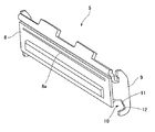
(印刷ヘッドおよびその支持構造)
図2はサーマルヘッドの斜視図である。図1、図2に示すように、サーマルヘッド5は、プラテンローラー4の側を向いているヘッド本体部8と、ヘッド本体部8の背面側において上下方向に延びている支持フレーム9を備えている。ヘッド本体部8の上端寄りの部分には、記録紙2を加熱して印刷を行うための発熱部8aが設けられている。サーマルヘッド5は、印刷を行うときには、ヘッド本体部8における発熱部8aの部分をプラテンローラー4に正対させ、発熱部8aとプラテンローラー4との間に記録紙2を挟み込んだ状態を形成する。
(Print head and its support structure)
FIG. 2 is a perspective view of the thermal head. As shown in FIGS. 1 and 2, the
支持フレーム9は、ヘッド本体部8の下方に向かって延びている部分、すなわち、発熱部8aよりも基準搬送方向の上流側に向かって延びている部分に形成された切り欠き部10を備えている。この切り欠き部10は、搬送経路3が設けられている側に向かって開口しており、ヘッド本体部8におけるプラテンローラー4による押圧部位に近い側、すなわち、発熱部8aに近い側が浅く、発熱部8aから遠い側が深い形状となっている。切り欠き部10の底部には直線状のガイド面11が設けられ、ガイド面11の下端には湾曲形状の回転支持面12が連続して形成されている。ここで、ガイド面11はヘッド本体部8に対して傾斜して延びており、その傾斜方向は、回転支持面12の側(図1の下側)に向かうに従ってヘッド本体部8の背面側(図1の右側)に後退する方向となっている。
The
ヘッド本体部8をプラテンローラー4に対峙させるようにサーマルヘッド5を配置すると、サーマルプリンター1の本体フレームに支持されている回転軸13が切り欠き部10の開口側に面した状態となる。回転軸13は、プラテンローラー4の回転軸線と平行に設けられている。サーマルヘッド5は、ヘッド本体部8の背面側に設けられたヘッド押圧バネ14(付勢部材)によってプラテンローラー4の側に付勢されている。ヘッド押圧バネ14の付勢力により、ヘッド本体部 8がプラテンローラー4に押し付けられると共に、切り欠き部10の内側面に回転軸13が押し付けられた状態が形成される。
When the
図1に示すように、プラテンローラー4に発熱部8aを正対させると、回転軸13は、切り欠き部10の下端に位置し、回転支持面12に内接した状態となる。このとき、回転軸13の外周面に回転支持面12を摺接させてサーマルヘッド5を回転させることが可能である。すなわち、回転軸13を中心としてサーマルヘッド5が回転可能に支持された状態が形成されている。
As shown in FIG. 1, when the
また、回転軸13は、サーマルヘッド5が記録紙2の基準搬送方向の上流側もしくは下流側(図1の上向き方向もしくは下向き方向)に引っ張られた場合には、ガイド面11に沿ってスライドすることにより、ヘッド押圧バネ14の付勢力に対向してサーマルヘッド5を支持しながら、サーマルヘッド5をガイドして、引っ張り方向に応じた方向に移動させる。つまり、サーマルヘッド5は、回転軸13およびガイド面11を設けたことにより、ガイド面11に沿って回転軸13がスライドするときの動作範囲内で回転軸13に対して相対移動可能に支持されている。
Further, the rotating
(記録紙の貼り付き状態解消動作)
図3は印刷ヘッドにおける記録紙の貼り付き状態解消動作を示す説明図であり、図3(a)は印刷ヘッドと記録紙との貼り付きが発生した状態、図3(b)は印刷ヘッドを移動させて貼り付き部分を押圧から開放した状態、図3(c)は貼り付き解消後に元の位置まで印刷ヘッドを戻した状態を示している。
(Recording paper sticking state elimination operation)
3A and 3B are explanatory views showing the operation of eliminating the sticking state of the recording paper in the print head. FIG. 3A shows a state where sticking between the printing head and the recording paper has occurred, and FIG. FIG. 3 (c) shows a state in which the print head is returned to the original position after the sticking is released.
本実施形態では、記録紙2に印刷を行うときには、図1および図3(a)に示すように、回転軸13が回転支持面12に内接する位置にサーマルヘッド5が位置決めされ、発熱部8aがプラテンローラー4における最もサーマルヘッド5の側に突出した部分に正対している。そして、ヘッド押圧バネ14により、回転軸13を中心としてサーマルヘッド5がプラテンローラー4の側に旋回する方向に 付勢され、発熱部8aがプラテンローラー4との間に記録紙2を挟んだ状態でプラテンローラー4側に押し付けられている。サーマルプリンター1の印刷待機状態では、この状態が維持されている。このため、印刷待機状態が長時間続くと、発熱部8aを中心とする被押圧領域Cに押し付けられていた記録紙2が、プラテンローラー4側からの押圧力により、被押圧領域Cに貼り付いた状態が形成される。
In the present embodiment, when printing on the
図4は貼り付き状態解消動作のフローチャートである。サーマルプリンター1の制御部は、印刷開始命令などの記録紙2の搬送を伴う動作の実行命令を受信した場合には、その時点での待機時間T(印刷待機状態の継続時間)が、予め設定した限度時間T0を越えているか否かを判断する(ステップS1)。そして、限度時間T0を越えて印刷待機状態が継続していた場合には(ステップS1:Yes)、ステップS2に進む。一方、待機時間Tが限度時間T0以内であった場合には(ステップS1:No)、ステップS2〜S3を省略してステップS4に進み、印刷動作などの指示された動作を開始する。
FIG. 4 is a flowchart of the sticking state elimination operation. When the control unit of the
サーマルプリンター1の制御部は、ステップS2において、記録紙2を基準搬送方向とは逆向きに所定量搬送するための搬送動作を行う。例えば、サーマルヘッド5によって形成される印刷ドットの24ドット分の長さに相当する搬送量だけ記録紙2を逆送するために、プラテンローラー4を24ドット分の逆送りに相当する回転量だけ逆回転させる。このようにすると、被押圧領域Cに貼り付いている記録紙2の部分に、基準搬送方向の上流側に向かう搬送力が作用し、記録紙2を介してサーマルヘッド5が基準搬送方向の上流側に引っ張られる。
In step S2, the control unit of the
サーマルヘッド5は、ガイド面11に沿って回転軸13がスライド可能であるため、プラテンローラー4に対して相対移動可能な取り付け状態となっている。従って、被押圧領域Cに貼り付いた記録紙2を介して上流側に引っ張られると、回転軸13をガイド面11に沿ってスライドさせながら、全体として引っ張り方向と同じ側に移動する。このように、プラテンローラー4に対してサーマルヘッド5を相対移動させると、押圧位置が被押圧領域Cから基準搬送方向の下流側に向かってずれてゆく。ステップS2の逆送量は、図3(b)に示すように、被押圧領域Cがプラテンローラー4による押圧位置から完全に外れるまでサーマルヘッド5を移動させることが可能な搬送量である。従って、ステップS2を行うことにより、被押圧領域Cが上流側に移動して押圧から完全に開放される。
Since the
また、サーマルヘッド5は、ステップS2において移動するとき、ヘッド本体部8の上部が押し付けられているプラテンローラー4、および、ガイド面11に押し付けられている回転軸13によって動きが規制されている。この規制により、サーマルヘッド5は、引っ張り力と完全に同じ移動方向には移動せず、全体として上部をプラテンローラー4側に傾ける方向(図3(b)では反時計回りの方向)にわずかに旋回しながら、ガイド面11と平行な右斜め下向きに下降する方向に移動することとなる。従って、被押圧領域Cは通常の搬送経路3を外れた位置に移動し、被押圧領域Cに貼り付いた記録紙2もまた、通常の搬送経路3を外れた位置に移動する。これにより、被押圧領域Cの上流側において、記録紙2がヘッド面から所定の立ち上がり角度Eをなすように斜めに立ち上がる姿勢となり、被押圧領域Cから記録紙2を剥がし起こす力(図3(b)のF方向に作用する力)が作用する。よって、従来のせん断力によって剥がす方法よりも容易に記録紙2が剥がれる。
Further, when the
更に、本実施形態では、上流側の搬送経路3には、プラテンローラー4の手前まで延びる紙案内部材6が設けられ、記録紙2をガイドしている。従って、被押圧領域Cが通常の搬送経路3を外れた位置に移動した場合には、紙案内部材6から被押圧領域Cまでの狭い区間において、記録紙2は、図3(b)において破線で示すたわみ経路Dに沿ってたわんだ状態となる。このたわみ状態は、記録紙2がヘッド面から立ち上がる部分において、立ち上がり角度Eが大きいたわみ状態であり、被押圧領域Cから記録紙2を剥がし起こす力が大きいたわみ状態である。つまり、この状態を形成することにより、記録紙2を高い成功率で剥がすことができる。記録紙2の立ち上がり角度Eは、サーマルヘッド5を図3(a)の位置から図3(b)の位置まで移動させる過程で徐々に増大するため、記録紙2を剥がし起こす力は徐々に増大する。よって、記録紙2をスムーズに剥がすことができる。
Furthermore, in this embodiment, a paper guide member 6 extending to the front side of the
なお、紙案内部材6を省略した場合には、上流側で記録紙2の経路が規制されないため、記録紙2が大きくゆるやかにたわむことが可能になる。従って、記録紙2の立ち上がり角度Eがそれほど大きくならない。但し、剥がし起こす力は作用するため、従来のせん断力によって剥がす方法よりは容易に剥がすことができる。また、被押圧領域Cの移動先が通常の搬送経路3を大きく外れていない場合においても、逆送による記録紙2のたわみは生じるため、上記の場合ほど大きくはないものの、剥がし起こす力は作用する。よって、従来のせん断力のみによる方法よりも容易に記録紙2を剥がすことができる。
If the paper guide member 6 is omitted, the path of the
サーマルプリンター1の制御部は、ステップS2の動作が完了した後には、ステップS3に進み、ステップS2の逆送量と同一の搬送量だけ記録紙を正方向(基準搬送方向)に搬送する。例えば、プラテンローラー4を24ドット分の正送りに相当する回転量だけ正回転させる。これにより、図3(c)に示すように、記録紙2が待機前の位置に戻り、記録紙2の印刷開始位置がプラテンローラー4による挟み込み位置Pに位置決めされる。また、基準搬送方向に搬送される記録紙2に押し付けられているサーマルヘッド5が記録紙2と共に下流側に引っ張られ、ステップS2で移動した移動経路を逆向きに移動して、発熱部8aとプラテンローラー4との間に記録紙2を挟んだ状態が形成される。なお、このとき、ガイド面11が傾斜しているため、ヘッド押圧バネ14の付勢力が、サーマルヘッド5全体をガイド面11の方向に沿って斜め左上側にスライドさせる力として作用する。以上により、サーマルヘッド5が復帰したら、ステップS4に進み、印刷動作などの指示された動作を開始する。
After the operation of step S2 is completed, the control unit of the
以上のように、本実施形態のサーマルプリンター1は、ヘッド本体部8に貼り付いた記録紙2をプラテンローラー4による押圧から開放して剥がし起こす方向の力を作用させることが可能な、サーマルヘッド5の支持機構を備えている。そして、これにより、容易且つ確実に貼り付き状態を解消することができる。また、この支持機構によるサーマルヘッド5の可動範囲内でサーマルヘッドを移動させる貼り付き状態解消動作を、プラテンローラー4の正逆回転動作のみで実施することができる。従って、サーマルヘッドを移動させるための駆動源を新たに設ける必要がなく、低コストで貼り付き解消を実現できる。
As described above, the
(改変例)
(1)上記実施形態では、基準搬送方向の上流側に記録紙2を搬送してプラテンローラー4による押圧位置をずらしていたが、基準搬送方向の下流側に記録紙2を搬送して、貼り付き部位を押圧から開放することも可能である。例えば、サーマルヘッド5および回転軸を、プラテンローラー4による押圧位置を基準として図1の上下方向を逆転させて配置すればよい。このような構成により、基準搬送方向への搬送によって貼り付き状態を解消することができる。また、このとき、紙出口1bの手前に紙案内部材を設けて、上記実施形態の紙案内部材6と同様に、記録紙2を剥がし起こす力を積極的に作用させることも可能である。
(Modification example)
(1) In the above embodiment, the
(2)上記実施形態では、貼り付き状態解消動作として、逆送動作および正方向への搬送動作を1回ずつ行うものであったが、逆送動作および正方向への搬送動作を複数回行うようにしてもよい。これにより、強く貼り付いている記録紙2をより確実に剥がすことができる。
(2) In the above embodiment, as the sticking state elimination operation, the reverse feeding operation and the forward conveying operation are performed once, but the backward feeding operation and the forward conveying operation are performed a plurality of times. You may do it. Thereby, it is possible to more reliably peel off the strongly attached
(3)上記実施形態では、搬送経路3の側に開口した切り欠き部10を設けて、この底部に回転軸13をスライドさせるガイド面11を設けていたが、切り欠き部10の代わりに、ガイド面11と同一方向に延びる長穴などを形成して、この長穴に回転軸13を取り付ける構成としても良い。
(3) In the above embodiment, the
(4)上記実施形態のステップS3におけるサーマルヘッド5の復帰をより確実にするために、予め、サーマルヘッド5を上側(基準搬送方向の下流側)に引っ張る付勢部材などを設けておいてもよい。
(4) In order to ensure the return of the
(5)上記実施形態は、発熱部8aを中心として記録紙2がサーマルヘッド5に貼り付くものであったが、貼り付き位置(記録紙2の挟み込み位置)は発熱部8aが設けられた部位に限定されるものではない。
(5) In the above embodiment, the
(6)上記実施形態は、本発明をサーマルプリンター1に適用したものであったが、他のプリンターにも適用できる。すなわち、本発明は、プラテンローラーと印刷ヘッドとの間に記録媒体を挟んで押圧し、印刷待機時にはこの押圧状態のまま放置されることによって記録媒体が印刷ヘッドに貼り付く可能性がある任意のプリンターに適用できる。また、記録媒体として印刷面にコート層を有する紙やラベル紙を印刷するプリンターに適用できる。
(6) In the above embodiment, the present invention is applied to the
(7)上記実施形態では、記録紙2を搬送するための搬送力によってサーマルヘッド5を引っ張って移動させていたが、記録紙2の搬送手段とは別の駆動源によってサーマルヘッド5を移動させてプラテンローラー4との当接位置をずらすように構成してもよい。また、記録紙2の搬送手段とは別の駆動源は、プラテンローラー4の回転力をアシストする駆動源としてもよい。
(7) In the above embodiment, the
(8)上記実施形態のサーマルプリンター1の構成は、プラテンローラー4と当接するヘッド本体部8は、鉛直面に平行な面で記載されているが、この姿勢には限定されない。プラテンローラー4に対してヘッド本体部8が鉛直面に傾斜して当接させてもよい。この様に当接させた際にも、プラテンローラー4とヘッド本体部8とのニップ領域である被押圧領域C(図3中のヘッド本体部8に記載されたハッチング部)の記録媒体搬送方向の中心を通る鉛直面よりもプラテンローラー側に紙入り口1a、紙案内部材7を配置するのと同様に配置することで上記実施形態と同じ効果を得ることができる。すなわち、紙入り口1a、及び紙案内部材の配置を被押圧領域Cの紙搬送方向の中心を通るプラテンローラー4の接線を含む仮想面よりもプラテンローラー4の側とする。これにより、記録紙をプラテンローラー4に巻き付けることができる。また、支持機構を構成する支持フレーム9に形成されたガイド面11を仮想面から離れる方向に延伸させることによりサーマルプリンター1の本体に構成された回転軸13に沿ってガイド面11が摺接して支持フレーム9が移動する。支持フレーム9の移動により、支持フレーム9に支持されたヘッド本体部8は移動し、ヘッド本体部8の被押圧領域Cは押圧が解除される位置までシフトする。この時、回転軸13は仮想面に対してヘッド本体部8側に配置する。
(8) In the configuration of the
(9)上記実施形態のサーマルプリンター1の制御部は、ステップS2において、サーマルヘッド5によって形成される印刷ドットの24ドット分逆送りに相当する回転量だけ回転させる制御を行なっている。ここでサーマルヘッド5によって形成される印刷ドット24分は、被押圧領域Cに相当する移動量よりも十分に大きい距離を搬送させた構成である。従って上記動作で本願は必ずしも限定されない。本実施形態の被押圧領域Cの紙搬送方向の距離Lは、ヘッド本体部8とプラテンローラー4の押圧力やプラテンローラー4の硬度によって変わるが、印刷ドット10〜12ドット程度である。
(9) The control unit of the
本願の構成は、サーマルヘッド5への記録紙2の貼り付きを防止するものである。サーマルヘッド5の印刷部である発熱部8aによる貼り付きを解消させるには、以下の動作を行なう。サーマルヘッド5を紙搬送方向の上流側に移動させて解消する動作を行なう場合には、被押圧領域Cの紙搬送方向の上流端から発熱部8aまでの距離L1(<L)以上の距離分、サーマルヘッド5(すなわちヘッド本体部8)を移動させる。一方、サーマルヘッド5を紙搬送方向の下流側に移動させて解消する動作を行なう場合には、被押圧領域Cの紙搬送方向の下流端から発熱部8aまでの距離L2(<L)以上の距離分、サーマルヘッド5(すなわちヘッド本体部8)を移動させる。発熱部8aが被押圧領域の中央にある場合には、L1=L2=1/2Lとなる。即ち、サーマルヘッド5の移動方向側の被押圧領域Cの端部から発熱部8aまでの紙搬送方向の距離移動させることにより、発熱部8aによる貼り付きを解消することができる。
The configuration of the present application prevents the
また、被押圧領域Cの押圧による貼り付きを解消するには、少なくとも被押圧領域Cの紙搬送方向の距離Lもしくは距離L以上移動させる。これにより、印刷待機時に押圧された被押圧領域Cに対応する記録紙Cの押圧が解除され、貼り付きを解消することができる。 Further, in order to eliminate sticking of the pressed area C due to pressing, the pressed area C is moved at least a distance L in the paper conveyance direction or a distance L or more. Thereby, the pressing of the recording paper C corresponding to the pressed area C pressed at the time of printing standby is released, and sticking can be eliminated.
(10)上記実施形態では、紙案内部材6を省略した場合にも剥がし起こす力が作用する。これは、サーマルヘッド5が紙搬送方向の上流側に移動するときには記録紙2の紙搬送方向の下流側は、被押圧領域Cに対応する位置の記録紙とは異なる位置の記録紙がヘッド本体部8とプラテンローラー4との押圧により支持される。一方、記録紙2の紙搬送方向の上流側は、紙入り口1aや、記録紙2としてロール紙を用いた場合にロールにより記録紙2の上流端側が支持される。紙案内部材6よりもサーマルヘッド5から離れた位置で記録紙2の上流端を支持しているので剥がし起こす力は弱くなるが、引き剥がし力は作用する。
(10) In the above-described embodiment, even when the paper guide member 6 is omitted, the force that causes peeling acts. This is because when the
(11)上記実施形態の待機時間T(印刷待機状態の継続時間)は、プラテンローラー4とヘッド本体部8との押圧で形成されるニップ領域(印刷待機時の被押圧領域)に記録紙2が停止し始めた時から、記録紙2の搬送動作を伴う印字開始命令を受信するまでの時間である。具体的な例としては、印刷動作が終了して、ヘッド本体部8がプラテンローラー4に押圧した状態でプラテンローラー4が停止してから、次の印刷命令を受信するまでの時間である。この時間を図示されないタイマー(計時手段)で計測して計測された情報から待機時間を求める。プラテンローラー4が停止した状態で電源がオフになった場合でもプラテンローラー4とヘッド本体部8とが押圧している状態が継続している構成の場合には、タイマーで電源オフ時も待機時間として計測する。
(11) The waiting time T (continuation time of the printing standby state) of the above embodiment is the
(12)上記の実施形態では、ステップS2の動作が完了した後には、ステップS3に進み、ステップS2noの逆送量と同一の範送量だけ記録紙を正方向に搬送しているが、この動作に限定されない。例えば、印刷待機時の被押圧領域Cに位置した記録紙2に印刷することを避ける場合には逆送量よりも長い距離搬送させることができる。印刷待機時に被押圧領域Cに位置した記録紙2の全領域への印刷を避ける場合には、逆送量に被押圧領域の紙搬送方向の距離を加えた距離もしくはそれ以上の距離を移動させる。
(12) In the above embodiment, after the operation of step S2 is completed, the process proceeds to step S3, and the recording paper is conveyed in the forward direction by the same feed amount as the reverse feed amount of step S2no. It is not limited to operation. For example, in order to avoid printing on the
1…サーマルプリンター(プリンター)、1a…紙入り口、1b…紙出口、2…記録紙(記録媒体)、3…搬送経路、4…プラテンローラー、5…サーマルヘッド(印刷ヘッド)、6…紙案内部材(案内部材)、7…搬送モーター、8…ヘッド本体部、8a…発熱部、9…支持フレーム、10…切り欠き部、11…ガイド面、12…回転支持面、13…回転軸、14…ヘッド押圧バネ、A…正方向、B…基準搬送方向、C…被押圧領域、D…たわみ経路、E…立ち上がり角度、F…剥がし起こし方向、P…挟み込み位置。
DESCRIPTION OF
Claims (4)
前記記録媒体を印刷する印刷部を有して前記プラテンローラーと対峙するヘッド本体部を有する印刷ヘッドと、
前記ヘッド本体部を前記プラテンローラーに押圧し、前記プラテンローラーに前記ヘッド本体部を押圧した状態で前記ヘッド本体部が当接する前記プラテンローラーの位置を変化させる方向に、前記ヘッド本体部を移動させる支持機構と、を備え、
前記支持機構は、前記プラテンローラーの回転軸線と平行な回転軸と接触する回転支持面、及び前記回転支持面に連続して前記ヘッド本体部の前記プラテンローラーと当接する位置へ延びて前記回転支持面に向かうに従って前記ヘッド本体部の背面に延伸する方向に傾斜するガイド面を有し、
前記ヘッド本体部と前記プラテンローラーとの当接により、前記回転支持面もしくは前記ガイド面は前記回転軸に押圧し、
前記ガイド面に沿って前記回転軸が相対的に移動して前記ヘッド本体部の前記プラテンローラーと当接する位置を移動させ、前記回転支持面で前記支持機構を回転させて前記ヘッド本体部が当接する前記プラテンローラーの位置を移動させることを特徴とするプリンター。 A platen roller for conveying a recording medium;
A print head having a print body for printing the recording medium and having a head main body facing the platen roller;
The head main body is pressed against the platen roller, and the head main body is moved in a direction to change the position of the platen roller with which the head main body abuts while the head main body is pressed against the platen roller. A support mechanism,
The support mechanism includes a rotation support surface that contacts a rotation axis parallel to a rotation axis of the platen roller, and a rotation support surface that extends to a position that contacts the platen roller of the head body portion continuously from the rotation support surface. A guide surface that is inclined in a direction extending toward the back surface of the head main body as it goes to the surface;
By the contact between the head main body and the platen roller, the rotation support surface or the guide surface is pressed against the rotation shaft,
The rotation shaft relatively moves along the guide surface to move the position of the head main body that contacts the platen roller, and the support mechanism is rotated by the rotation support surface to contact the head main body. A printer characterized by moving the position of the platen roller in contact therewith.
前記搬送経路に前記プラテンローラーに対して前記ヘッド本体部が移動する方向と同じ側に位置して前記記録媒体を案内する案内部材を有する請求項1ないし3のいずれか1項に記載のプリンター。 A conveyance path for conveying the recording medium to a position where the platen roller and the head main body abut,
4. The printer according to claim 1, further comprising: a guide member that guides the recording medium on the conveyance path on the same side as a direction in which the head main body moves with respect to the platen roller. 5.
Priority Applications (11)
| Application Number | Priority Date | Filing Date | Title |
|---|---|---|---|
| JP2011170775A JP5821376B2 (en) | 2010-08-17 | 2011-08-04 | printer |
| US13/210,451 US8446441B2 (en) | 2010-08-17 | 2011-08-16 | Print head, printer, and control method of printer |
| BRPI1106839-6A BRPI1106839A2 (en) | 2010-08-17 | 2011-08-16 | printhead, printer and printer control method |
| EP11177703.3A EP2420387B1 (en) | 2010-08-17 | 2011-08-16 | Print head, printer, and control method of printer |
| RU2013103086/12A RU2530421C2 (en) | 2010-08-17 | 2011-08-16 | Print head, printer and method of operating printer |
| KR1020110081350A KR101926192B1 (en) | 2010-08-17 | 2011-08-16 | Printing head, printer, and method for controlling a printer |
| RU2011134387/12A RU2481195C2 (en) | 2010-08-17 | 2011-08-16 | Printing head, printer and method of printer control |
| CN201510514607.6A CN105109212B (en) | 2010-08-17 | 2011-08-17 | print head and printer |
| CN201110235776.8A CN102416772B (en) | 2010-08-17 | 2011-08-17 | The control method of print head, printer and printer |
| US13/866,090 US8654163B2 (en) | 2010-08-17 | 2013-04-19 | Print head, printer, and control method of printer |
| US14/104,114 US8803930B2 (en) | 2010-08-17 | 2013-12-12 | Print head, printer, and control method of printer |
Applications Claiming Priority (3)
| Application Number | Priority Date | Filing Date | Title |
|---|---|---|---|
| JP2010182125 | 2010-08-17 | ||
| JP2010182125 | 2010-08-17 | ||
| JP2011170775A JP5821376B2 (en) | 2010-08-17 | 2011-08-04 | printer |
Publications (3)
| Publication Number | Publication Date |
|---|---|
| JP2012061848A JP2012061848A (en) | 2012-03-29 |
| JP2012061848A5 JP2012061848A5 (en) | 2014-08-07 |
| JP5821376B2 true JP5821376B2 (en) | 2015-11-24 |
Family
ID=44654012
Family Applications (1)
| Application Number | Title | Priority Date | Filing Date |
|---|---|---|---|
| JP2011170775A Active JP5821376B2 (en) | 2010-08-17 | 2011-08-04 | printer |
Country Status (7)
| Country | Link |
|---|---|
| US (3) | US8446441B2 (en) |
| EP (1) | EP2420387B1 (en) |
| JP (1) | JP5821376B2 (en) |
| KR (1) | KR101926192B1 (en) |
| CN (2) | CN105109212B (en) |
| BR (1) | BRPI1106839A2 (en) |
| RU (2) | RU2530421C2 (en) |
Families Citing this family (10)
| Publication number | Priority date | Publication date | Assignee | Title |
|---|---|---|---|---|
| JP5821376B2 (en) * | 2010-08-17 | 2015-11-24 | セイコーエプソン株式会社 | printer |
| JP5739848B2 (en) * | 2012-08-03 | 2015-06-24 | 東芝テック株式会社 | Printing apparatus and printing method |
| CN104275948B (en) * | 2013-07-04 | 2017-07-28 | 精工爱普生株式会社 | The alignment method of printing equipment, print head and printing equipment |
| JP6225567B2 (en) * | 2013-08-30 | 2017-11-08 | セイコーエプソン株式会社 | Print head and printing apparatus |
| JP6372982B2 (en) * | 2013-08-28 | 2018-08-15 | 富士通コンポーネント株式会社 | Printer device |
| JP6908877B2 (en) * | 2017-02-03 | 2021-07-28 | セイコーエプソン株式会社 | Printing equipment and printing method |
| JP2019006569A (en) * | 2017-06-26 | 2019-01-17 | カシオ計算機株式会社 | Printer, printer control method, and program |
| CN107234878B (en) * | 2017-07-27 | 2019-09-27 | 厦门汉印电子技术有限公司 | A kind of driving device and its thermal printer of print head |
| JP7307894B2 (en) * | 2019-09-26 | 2023-07-13 | 大日本印刷株式会社 | THERMAL TRANSFER SYSTEM AND THERMAL TRANSFER METHOD |
| JP2023046473A (en) * | 2021-09-24 | 2023-04-05 | カシオ計算機株式会社 | Printing device and printing method |
Family Cites Families (27)
| Publication number | Priority date | Publication date | Assignee | Title |
|---|---|---|---|---|
| JPS6230057A (en) * | 1985-07-31 | 1987-02-09 | Canon Inc | Heat-transfer recording device |
| JPS6392465A (en) * | 1986-10-08 | 1988-04-22 | Nec Corp | Thermal transfer printer |
| JP2710656B2 (en) * | 1989-02-06 | 1998-02-10 | シャープ株式会社 | Recording device |
| JPH0214394A (en) * | 1989-05-25 | 1990-01-18 | Kubota Ltd | Method for printing and note issuing in automatic vending machine |
| JPH034174A (en) | 1989-05-31 | 1991-01-10 | Nippondenso Co Ltd | Speed detecting device for vehicle |
| JPH04369961A (en) * | 1991-04-08 | 1992-12-22 | Ricoh Co Ltd | Printer and image reader |
| JPH05155100A (en) * | 1991-12-04 | 1993-06-22 | Seiko Instr Inc | Mechanism for retaining thermal head |
| JP2825716B2 (en) * | 1992-10-16 | 1998-11-18 | シャープ株式会社 | Thermal printing mechanism |
| JPH07309052A (en) * | 1994-05-18 | 1995-11-28 | Asahi Optical Co Ltd | Thermal printer |
| JP3004174B2 (en) * | 1994-07-29 | 2000-01-31 | 沖電気工業株式会社 | Thermal printer |
| DE69710634D1 (en) * | 1996-05-09 | 2002-04-04 | Agfa Gevaert Nv | Thermal printing device with printhead adjustment |
| JPH09314944A (en) * | 1996-05-29 | 1997-12-09 | Seiko Epson Corp | Thermal printer |
| JP3659535B2 (en) * | 1996-09-17 | 2005-06-15 | 株式会社サトー | Head position adjustment device for thermal printer |
| JPH10157052A (en) | 1996-12-04 | 1998-06-16 | Tohoku Ricoh Co Ltd | Plate-making writing apparatus and plate-making printing apparatus |
| JP2000222536A (en) | 1999-01-28 | 2000-08-11 | Sankyo Seiki Mfg Co Ltd | Card reader and its control method |
| JP2000280499A (en) * | 1999-03-30 | 2000-10-10 | Matsushita Graphic Communication Systems Inc | Image-recording apparatus and method for recording image |
| JP4251014B2 (en) * | 2003-05-22 | 2009-04-08 | セイコーエプソン株式会社 | Printer and printer control method |
| JP4146292B2 (en) * | 2003-06-09 | 2008-09-10 | セイコーインスツル株式会社 | Printer device |
| JP2005035109A (en) * | 2003-07-17 | 2005-02-10 | Alps Electric Co Ltd | Thermal printer |
| US7059702B2 (en) * | 2004-06-25 | 2006-06-13 | Xerox Corporation | Systems and methods for determining printhead in a standby position |
| JP2006334858A (en) * | 2005-05-31 | 2006-12-14 | Sato Corp | Label printer and method of preventing label from sticking to thermal printing head |
| JP4817101B2 (en) | 2005-09-12 | 2011-11-16 | セイコーインスツル株式会社 | Thermal activation device, printing device and printer |
| JP5256893B2 (en) | 2008-07-07 | 2013-08-07 | セイコーエプソン株式会社 | RECORDING DEVICE, CONTROL METHOD AND CONTROL PROGRAM FOR RECORDING DEVICE |
| JP5155100B2 (en) * | 2008-10-27 | 2013-02-27 | パナソニック株式会社 | Tag reader device |
| JP2010182125A (en) | 2009-02-05 | 2010-08-19 | Cosmotopia Japan Inc | Learning support system |
| JP5268966B2 (en) | 2010-02-22 | 2013-08-21 | 京セラドキュメントソリューションズ株式会社 | Display control apparatus, image forming apparatus, display control method, and display control program |
| JP5821376B2 (en) * | 2010-08-17 | 2015-11-24 | セイコーエプソン株式会社 | printer |
-
2011
- 2011-08-04 JP JP2011170775A patent/JP5821376B2/en active Active
- 2011-08-16 US US13/210,451 patent/US8446441B2/en active Active
- 2011-08-16 BR BRPI1106839-6A patent/BRPI1106839A2/en not_active Application Discontinuation
- 2011-08-16 KR KR1020110081350A patent/KR101926192B1/en active IP Right Grant
- 2011-08-16 RU RU2013103086/12A patent/RU2530421C2/en active
- 2011-08-16 EP EP11177703.3A patent/EP2420387B1/en active Active
- 2011-08-16 RU RU2011134387/12A patent/RU2481195C2/en active
- 2011-08-17 CN CN201510514607.6A patent/CN105109212B/en active Active
- 2011-08-17 CN CN201110235776.8A patent/CN102416772B/en active Active
-
2013
- 2013-04-19 US US13/866,090 patent/US8654163B2/en active Active
- 2013-12-12 US US14/104,114 patent/US8803930B2/en active Active
Also Published As
| Publication number | Publication date |
|---|---|
| EP2420387A1 (en) | 2012-02-22 |
| US20130229480A1 (en) | 2013-09-05 |
| US20140098173A1 (en) | 2014-04-10 |
| US8654163B2 (en) | 2014-02-18 |
| CN102416772B (en) | 2015-09-23 |
| RU2530421C2 (en) | 2014-10-10 |
| CN105109212A (en) | 2015-12-02 |
| KR101926192B1 (en) | 2018-12-06 |
| JP2012061848A (en) | 2012-03-29 |
| RU2481195C2 (en) | 2013-05-10 |
| US8446441B2 (en) | 2013-05-21 |
| CN102416772A (en) | 2012-04-18 |
| BRPI1106839A2 (en) | 2013-03-26 |
| KR20120017007A (en) | 2012-02-27 |
| CN105109212B (en) | 2017-06-09 |
| RU2011134387A (en) | 2013-03-10 |
| EP2420387B1 (en) | 2015-03-25 |
| RU2013103086A (en) | 2014-07-27 |
| US8803930B2 (en) | 2014-08-12 |
| US20120044313A1 (en) | 2012-02-23 |
Similar Documents
| Publication | Publication Date | Title |
|---|---|---|
| JP5821376B2 (en) | printer | |
| JP5039805B2 (en) | Label printer | |
| JP5769466B2 (en) | Adhesive label issuing device and printer | |
| US10016989B1 (en) | Printing apparatus | |
| JP4752869B2 (en) | Head moving mechanism and image forming apparatus | |
| JP4594697B2 (en) | Label peeling method for label paper and label printer | |
| JP4883671B2 (en) | Thermal activation device and printer | |
| JP4787772B2 (en) | Thermal activation device, printer, thermal activation method, and adhesive label manufacturing method | |
| JP5613703B2 (en) | Label peeling device | |
| JP4858267B2 (en) | Printer device | |
| JP4921796B2 (en) | Printer and recording method | |
| JP2012206369A (en) | Printer and control method thereof | |
| JP4409599B2 (en) | Card printer | |
| JP6324062B2 (en) | Printer | |
| JP2010221664A (en) | Device and method for issuing thermosensitive self-adhesive label | |
| JP5309833B2 (en) | Print object slack formation mechanism of thermal transfer printer and thermal transfer printer | |
| JP2023091967A (en) | Printing device, printing method and printing control program | |
| JP2008210097A (en) | Receipt printing and issuing apparatus | |
| JP2006199442A (en) | Intermediate transfer type thermal transfer printer, and its film peeling method | |
| JP2006181732A (en) | Intermediate transfer type thermal transfer printing apparatus and method for releasing its film | |
| JP2006095949A (en) | Booklet processing equipment | |
| JP2006181733A (en) | Image printing method in intermediate transfer type thermal transfer printing apparatus | |
| JP2016078381A (en) | Medium cartridge and printer | |
| JP2004161402A (en) | Printing device | |
| JP2004209815A (en) | Printer |
Legal Events
| Date | Code | Title | Description |
|---|---|---|---|
| A521 | Request for written amendment filed |
Free format text: JAPANESE INTERMEDIATE CODE: A523 Effective date: 20140624 |
|
| A621 | Written request for application examination |
Free format text: JAPANESE INTERMEDIATE CODE: A621 Effective date: 20140624 |
|
| RD04 | Notification of resignation of power of attorney |
Free format text: JAPANESE INTERMEDIATE CODE: A7424 Effective date: 20150106 |
|
| A977 | Report on retrieval |
Free format text: JAPANESE INTERMEDIATE CODE: A971007 Effective date: 20150406 |
|
| A131 | Notification of reasons for refusal |
Free format text: JAPANESE INTERMEDIATE CODE: A131 Effective date: 20150414 |
|
| A521 | Request for written amendment filed |
Free format text: JAPANESE INTERMEDIATE CODE: A523 Effective date: 20150522 |
|
| TRDD | Decision of grant or rejection written | ||
| A01 | Written decision to grant a patent or to grant a registration (utility model) |
Free format text: JAPANESE INTERMEDIATE CODE: A01 Effective date: 20150908 |
|
| A61 | First payment of annual fees (during grant procedure) |
Free format text: JAPANESE INTERMEDIATE CODE: A61 Effective date: 20150921 |
|
| R150 | Certificate of patent or registration of utility model |
Ref document number: 5821376 Country of ref document: JP Free format text: JAPANESE INTERMEDIATE CODE: R150 |
|
| S531 | Written request for registration of change of domicile |
Free format text: JAPANESE INTERMEDIATE CODE: R313531 |
|
| R350 | Written notification of registration of transfer |
Free format text: JAPANESE INTERMEDIATE CODE: R350 |