RU2481195C2 - Printing head, printer and method of printer control - Google Patents
Printing head, printer and method of printer control Download PDFInfo
- Publication number
- RU2481195C2 RU2481195C2 RU2011134387/12A RU2011134387A RU2481195C2 RU 2481195 C2 RU2481195 C2 RU 2481195C2 RU 2011134387/12 A RU2011134387/12 A RU 2011134387/12A RU 2011134387 A RU2011134387 A RU 2011134387A RU 2481195 C2 RU2481195 C2 RU 2481195C2
- Authority
- RU
- Russia
- Prior art keywords
- support roller
- head
- recording medium
- head housing
- print head
- Prior art date
Links
- 238000007639 printing Methods 0.000 title claims abstract description 30
- 238000000034 method Methods 0.000 title claims abstract description 18
- 230000000694 effects Effects 0.000 abstract description 2
- 239000000126 substance Substances 0.000 abstract 1
- 238000010438 heat treatment Methods 0.000 description 21
- 238000011144 upstream manufacturing Methods 0.000 description 17
- 238000007665 sagging Methods 0.000 description 3
- 230000005540 biological transmission Effects 0.000 description 2
- 238000010276 construction Methods 0.000 description 2
- 238000005452 bending Methods 0.000 description 1
- 230000006835 compression Effects 0.000 description 1
- 238000007906 compression Methods 0.000 description 1
- 230000008030 elimination Effects 0.000 description 1
- 238000003379 elimination reaction Methods 0.000 description 1
- 238000012986 modification Methods 0.000 description 1
- 230000004048 modification Effects 0.000 description 1
- 238000010008 shearing Methods 0.000 description 1
- 238000009751 slip forming Methods 0.000 description 1
Images
Classifications
-
- B—PERFORMING OPERATIONS; TRANSPORTING
- B41—PRINTING; LINING MACHINES; TYPEWRITERS; STAMPS
- B41J—TYPEWRITERS; SELECTIVE PRINTING MECHANISMS, i.e. MECHANISMS PRINTING OTHERWISE THAN FROM A FORME; CORRECTION OF TYPOGRAPHICAL ERRORS
- B41J11/00—Devices or arrangements of selective printing mechanisms, e.g. ink-jet printers or thermal printers, for supporting or handling copy material in sheet or web form
- B41J11/02—Platens
- B41J11/04—Roller platens
-
- B—PERFORMING OPERATIONS; TRANSPORTING
- B41—PRINTING; LINING MACHINES; TYPEWRITERS; STAMPS
- B41J—TYPEWRITERS; SELECTIVE PRINTING MECHANISMS, i.e. MECHANISMS PRINTING OTHERWISE THAN FROM A FORME; CORRECTION OF TYPOGRAPHICAL ERRORS
- B41J11/00—Devices or arrangements of selective printing mechanisms, e.g. ink-jet printers or thermal printers, for supporting or handling copy material in sheet or web form
- B41J11/36—Blanking or long feeds; Feeding to a particular line, e.g. by rotation of platen or feed roller
- B41J11/42—Controlling printing material conveyance for accurate alignment of the printing material with the printhead; Print registering
-
- B—PERFORMING OPERATIONS; TRANSPORTING
- B41—PRINTING; LINING MACHINES; TYPEWRITERS; STAMPS
- B41J—TYPEWRITERS; SELECTIVE PRINTING MECHANISMS, i.e. MECHANISMS PRINTING OTHERWISE THAN FROM A FORME; CORRECTION OF TYPOGRAPHICAL ERRORS
- B41J2/00—Typewriters or selective printing mechanisms characterised by the printing or marking process for which they are designed
- B41J2/315—Typewriters or selective printing mechanisms characterised by the printing or marking process for which they are designed characterised by selective application of heat to a heat sensitive printing or impression-transfer material
- B41J2/32—Typewriters or selective printing mechanisms characterised by the printing or marking process for which they are designed characterised by selective application of heat to a heat sensitive printing or impression-transfer material using thermal heads
-
- B—PERFORMING OPERATIONS; TRANSPORTING
- B41—PRINTING; LINING MACHINES; TYPEWRITERS; STAMPS
- B41J—TYPEWRITERS; SELECTIVE PRINTING MECHANISMS, i.e. MECHANISMS PRINTING OTHERWISE THAN FROM A FORME; CORRECTION OF TYPOGRAPHICAL ERRORS
- B41J25/00—Actions or mechanisms not otherwise provided for
- B41J25/304—Bodily-movable mechanisms for print heads or carriages movable towards or from paper surface
- B41J25/316—Bodily-movable mechanisms for print heads or carriages movable towards or from paper surface with tilting motion mechanisms relative to paper surface
Abstract
Description
Раскрытие японской заявки на патент № 2010-182125, зарегистрированной 17 августа 2010 г., и заявки № 2011-170775, включая описания, чертежи и формулы изобретения, полностью включены в этот документ по ссылке.The disclosure of Japanese Patent Application No. 2010-182125, registered on August 17, 2010, and Application No. 2011-170775, including descriptions, drawings and claims, are hereby incorporated by reference in their entireties.
Предпосылки создания изобретенияBACKGROUND OF THE INVENTION
Настоящее изобретение относится к поддерживающему механизму для печатающей головки, принтеру и способу управления принтером, в частности к поддерживающему механизму для печатающей головки в принтере, которая осуществляет печать, при этом транспортируя носитель записи посредством вращательного приведения опорного ролика в состояние, в котором носитель записи зажат и прижат между печатающей головкой и опорным роликом, к принтеру, содержащему поддерживающий механизм для печатающей головки, и способу управления принтером.The present invention relates to a support mechanism for a print head, a printer, and a method for controlling a printer, in particular, a support mechanism for a print head in a printer that prints while transporting a recording medium by rotationally bringing the support roller to a state in which the recording medium is pinched and pressed between the print head and the support roller, to a printer containing a support mechanism for the print head, and a method for controlling the printer.
Существует принтер, включающий в себя печатающую головку и опорный ролик, который расположен так, чтобы быть обращенным к печатающей головке. Принтер осуществляет печать, при этом транспортируя носитель записи посредством зажимания носителя записи между печатающей головкой и опорным роликом. Иногда принтер переходит в состояние ожидания при условии, что носитель записи зажат между печатающей головкой и опорным роликом, и может пройти много времени при условии, что носитель записи прижат к печатающей головке. В таком принтере, когда печать осуществляется на носителе записи, который склонен к прилипанию в прижатом состоянии, таком как носитель записи, имеющий поверхность печати, на которую нанесено покрытие, существует возможность того, что носитель записи прилипнет к печатающей головке в случае, если носитель записи оставлен в состоянии ожидания надолго.There is a printer including a print head and a support roller that is positioned so as to face the print head. The printer prints while transporting the recording medium by clamping the recording medium between the print head and the support roller. Sometimes the printer enters a standby state provided that the recording medium is sandwiched between the print head and the support roller, and it may take a long time if the recording medium is pressed against the print head. In such a printer, when printing is carried out on a recording medium that is prone to adhering in a pressed state, such as a recording medium having a coated print surface, it is possible for the recording medium to adhere to the print head if the recording medium left pending for a long time.
В JP-A-2006-334858 описан термопринтер, который осуществляет операцию для устранения прилипания, которое случается из-за состояния, в котором носитель записи (этикетка) прижат к печатающей головке (термоголовке) надолго. В термопринтере, когда состояние ожидания печати продолжается в течение заданного периода времени или более, осуществляется управление вращательным приведением опорного ролика в направлениях вперед и назад при условии, что печатающая головка зафиксирована, и посредством этого носитель записи, прилипший к печатающей головке, неоднократно тянется назад и вперед в направлении транспортирования носителя записи так, чтобы быть отслоенным от печатающей головки.JP-A-2006-334858 describes a thermal printer that performs an operation to eliminate sticking that occurs due to a condition in which the recording medium (label) is pressed against the print head (thermal head) for a long time. In the thermal printer, when the print standby state continues for a predetermined period of time or more, the rotation of the support roller in the forward and backward directions is controlled provided that the printhead is fixed, and thereby the recording medium adhered to the printhead is repeatedly pulled back and forward in the transport direction of the recording medium so as to be peeled off from the print head.
В JP-A-2006-334858 описана конфигурация, в которой носитель записи должен быть перемещен в направлениях назад и вперед при условии, что печатающая головка прижата и прикреплена к опорному ролику, и носитель записи отслаивается от печатающей головки сдвигающей силой. Тем не менее, в случае если носитель записи сильно прилип к печатающей головке, сдвигающая сила, необходимая для отслаивания носителя записи от печатающей головки, превосходит поворачивающую движущую силу опорного ролика посредством обычного двигателя и выходит за диапазон эффективности передачи силы из-за трения или подобного между обычным опорным роликом и носителем записи. Следовательно, существует возможность того, что опорный ролик будет проскальзывать и не сможет транспортировать носитель записи. Следовательно, носитель записи не сможет быть вытянутым посредством достаточной силы, так что существует возможность того, что прилипание не будет устранено.JP-A-2006-334858 describes a configuration in which the recording medium must be moved back and forth, provided that the print head is pressed and attached to the support roller, and the recording medium is peeled off from the print head by a shearing force. However, in the event that the recording medium adheres strongly to the print head, the shear force necessary to peel the recording medium away from the print head exceeds the rotational driving force of the support roller by a conventional motor and is beyond the range of transmission efficiency due to friction or the like between conventional support roller and recording medium. Therefore, there is a possibility that the support roller will slip and cannot transport the recording medium. Therefore, the recording medium cannot be elongated by sufficient force, so that there is a possibility that adhesion will not be removed.
Сущность изобретенияSUMMARY OF THE INVENTION
Следовательно, целью, по меньшей мере, одного варианта осуществления настоящего изобретения является разработка принтера, который может легко отслаивать носитель записи, даже в случае, если носитель записи сильно прилип к печатающей головке, и разработка поддерживающего механизма для печатающей головки принтера и способа управления принтером.Therefore, the aim of at least one embodiment of the present invention is to provide a printer that can easily peel a recording medium even if the recording medium is strongly adhered to the print head, and to develop a support mechanism for the print head of the printer and a method for controlling the printer.
Согласно особенности вариантов осуществления настоящего изобретения разработана печатающая головка, содержащая: часть корпуса головки, имеющую печатающую часть, которая осуществляет печать на носителе записи и обращена к опорному ролику, выполненному с возможностью транспортирования носителя записи; и поддерживающий механизм, который поддерживает печатающую головку, прижимает печатающую головку к опорному ролику и позволяет опорному ролику перемещать часть корпуса головки в таком направлении, чтобы место контакта части корпуса головки относительно опорного ролика смещалось, при этом сохраняя часть корпуса головки, прижатой к опорному ролику.According to a particular embodiment of the present invention, there is provided a print head comprising: a part of a head housing having a print part that prints on a recording medium and faces a support roller configured to transport the recording medium; and a supporting mechanism that supports the print head, presses the print head against the support roller and allows the support roller to move part of the head housing in such a way that the contact point of the part of the head housing relative to the support roller moves while keeping the part of the head housing pressed against the support roller.
С этой конфигурацией, в случае если носитель записи прилип к печатающей головке, возможно освободить часть, к которой прилип носитель записи (часть части корпуса головки, которая прижата опорным роликом) от давления опорного ролика. Например, посредством воздействия силы в направлении перемещения печатающей головки носитель записи и печатающая головка могут быть перемещены друг с другом так, чтобы часть, к которой прилип носитель записи, могла быть удалена от положения прижима опорного ролика. Когда часть освобождена от давления, возможно переместить носитель записи в направлении отслаивания и поднимания носителя записи от печатающей головки. В случае если носитель записи отслоен и поднят, носитель записи может быть отслоен посредством силы, меньшей, чем в случае, если он отслоен только посредством сдвигающей силы. К тому же, посредством перемещения печатающей головки при условии, что носитель записи прилип к печатающей головке, так, чтобы осуществить провисание носителя записи или переместить носитель записи к положению вне обычного пути транспортирования, возможно приложить силу, отслаивающую и поднимающую носитель записи от печатающей головки. Следовательно, возможно легко и успешно исключить прилипание носителя записи.With this configuration, if the recording medium has adhered to the print head, it is possible to release the part to which the recording medium (part of the part of the head body which is pressed by the support roller) adheres to from the pressure of the support roller. For example, by applying a force in the direction of movement of the print head, the recording medium and the print head can be moved with each other so that the portion to which the recording medium adhered can be removed from the pressing position of the support roller. When the part is relieved of pressure, it is possible to move the recording medium in the direction of peeling and lifting the recording medium from the print head. In the event that the recording medium is peeled and lifted, the recording medium may be peeled off by a force less than if it is peeled off only by a shear force. Moreover, by moving the print head, provided that the recording medium is adhered to the print head, so as to sag the recording medium or move the recording medium to a position outside the normal transport path, it is possible to apply a force peeling and lifting the recording medium from the print head. Therefore, it is possible to easily and successfully prevent sticking of the recording medium.
Часть корпуса головки может быть перемещена с поддерживающим механизмом посредством поворота опорного ролика в первом направлении или поворота опорного ролика во втором направлении, противоположном первому направлению. С этой конфигурацией возможно осуществить операцию устранения прилипания посредством операции транспортирования посредством использования существующего опорного ролика, так что отсутствует необходимость в предусматривании источника привода для перемещения печатающей головки. Следовательно, возможно достигнуть устранения прилипания с низкими затратами посредством избегания необходимости усложнения конструкции устройства. К тому же, поскольку носитель записи транспортируется в обычном направлении транспортирования носителя записи, возможно, чтобы носитель записи был отслоен со стороны вверх по потоку печатающей головки в направлении транспортирования, и возможно прилагать силу, отслаивающую и поднимающую носитель записи.A part of the head housing can be moved with the supporting mechanism by turning the support roller in the first direction or by turning the support roller in the second direction opposite to the first direction. With this configuration, it is possible to perform an anti-stick operation by the conveying operation by using an existing support roller, so that there is no need to provide a drive source for moving the print head. Therefore, it is possible to achieve the elimination of adhesion at low cost by avoiding the need to complicate the design of the device. Moreover, since the recording medium is transported in the normal transport direction of the recording medium, it is possible for the recording medium to be peeled off from the upstream side of the print head in the conveying direction, and it is possible to exert a force peeling and lifting the recording medium.
Поддерживающий механизм может включать в себя поверхность поддерживания вращения, которая контактирует с вращающимся валом, который параллелен линии оси вращения опорного ролика, и направляющую поверхность, которая непрерывна с поверхностью поддерживания вращения и которая простирается к стороне места контакта части корпуса головки относительно опорного ролика, причем поверхность поддерживания вращения направляющей поверхности может быть прижата к вращающемуся валу посредством контакта между частью корпуса головки и опорным роликом, причем вращающийся вал может перемещаться относительно и вдоль направляющей поверхности так, чтобы перемещать место контакта части корпуса головки относительно опорного ролика, и поддерживающий механизм может поворачиваться вокруг вращающегося вала и поверхности поддерживания вращения так, чтобы перемещать место контакта части корпуса головки относительно опорного ролика. С этой конфигурацией, поскольку на печатающей головке предусмотрена направляющая поверхность, и вращающийся вал, прижатый к направляющей поверхности, выполнен с возможностью быть сдвигаемым, печатающая головка может быть перемещена параллельно направлению смещения прижатой части, тогда как печатающая головка поддерживается вращающимся валом.The support mechanism may include a rotation support surface that contacts a rotating shaft that is parallel to the axis of rotation of the support roller, and a guide surface that is continuous with the rotation support surface and that extends to the side of the contact portion of the head housing relative to the support roller, the surface maintaining the rotation of the guide surface can be pressed against the rotating shaft by means of contact between the part of the head housing and the supporting role com, and the rotating shaft can move relative to and along the guide surface so as to move the contact point of the head housing relative to the support roller, and the support mechanism can rotate around the rotating shaft and the rotation supporting surface so as to move the contact point of the head housing relative to the support roller. With this configuration, since a guide surface is provided on the print head and the rotary shaft pressed against the guide surface is movable, the print head can be moved parallel to the direction of movement of the pressed portion, while the print head is supported by the rotary shaft.
В поддерживающем механизме направляющая поверхность может быть наклонена в направлении простирания к задней стороне части корпуса головки, по мере того как она идет к стороне поверхности поддерживания вращения. С этой конфигурацией, по мере того как вращающийся вал перемещается параллельно и вдоль направляющей поверхности для перемещения места прижима, печатающая головка может быть втянута к задней стороне части корпуса головки. Следовательно, по мере того как часть, к которой прилип носитель записи, отделяется от места прижима, часть перемещается к положению вне пути транспортирования. В связи с этим перемещением угол подъема носителя записи относительно поверхности прилипания увеличивается так, что может действовать большая сила, отслаивающая и поднимающая носитель записи от поверхности головки. Следовательно, возможно моментально устранять прилипание носителя записи.In the supporting mechanism, the guide surface may be inclined in the direction of extension to the rear side of the head housing portion as it goes to the side of the rotation supporting surface. With this configuration, as the rotary shaft moves parallel and along the guide surface to move the presser, the print head can be pulled toward the rear side of the head housing portion. Therefore, as the part to which the recording medium has adhered is detached from the clip, the part moves to a position outside the transport path. In connection with this movement, the angle of elevation of the recording medium relative to the adhesion surface increases so that a large force can exfoliate and lift the recording medium from the surface of the head. Therefore, it is possible to instantly eliminate the sticking of the recording medium.
Согласно другой особенности вариантов осуществления настоящего изобретения разработан принтер, содержащий: опорный ролик, выполненный с возможностью транспортирования носителя записи; печатающую головку, которая имеет часть корпуса головки, имеющую печатающую часть, которая осуществляет печать на носителе записи и обращена к опорному ролику; поджимающий элемент, который поджимает печатающую головку к опорному ролику; и поддерживающий механизм, который поддерживает печатающую головку, прижимает печатающую головку к опорному ролику и позволяет опорному ролику перемещать часть корпуса головки в таком направлении, чтобы место контакта части корпуса головки относительно опорного ролика смещалось, при этом сохраняя часть корпуса головки прижатой к опорному ролику.According to another aspect of the embodiments of the present invention, there is provided a printer comprising: a support roller configured to transport a recording medium; a print head, which has a part of the head housing having a print part, which prints on a recording medium and faces the support roller; a pressing member that presses the print head against the support roller; and a support mechanism that supports the print head presses the print head against the support roller and allows the support roller to move part of the head housing in such a way that the contact point of the part of the head housing relative to the support roller moves while keeping the part of the head housing pressed against the support roller.
Принтер может дополнительно содержать: путь транспортирования для транспортирования носителя записи к месту контакта между опорным роликом и частью корпуса головки; и направляющий элемент, расположенный на пути транспортирования у той же стороны, что и направление, в котором перемещается часть корпуса головки относительно опорного ролика, и выполненный с возможностью направления носителя записи. Таким образом, когда путь перемещения носителя записи ограничен посредством предусматривания направляющего элемента у стороны, где перемещается печатающая головка, носитель записи должен быть отслоен в коротком интервале от направляющего элемента до печатающей головки так, чтобы обязательно увеличился угол подъема относительно поверхности прилипания носителя записи. Соответственно, отслаивающая и поднимающая сила может действовать положительно.The printer may further comprise: a transportation path for transporting the recording medium to the contact point between the support roller and part of the head housing; and a guide element located on the transport path on the same side as the direction in which part of the head housing is moved relative to the support roller, and configured to direct the recording medium. Thus, when the travel path of the recording medium is limited by providing a guide element at the side where the print head moves, the recording medium must be peeled off in a short interval from the guide element to the print head so that the angle of elevation with respect to the adhesion surface of the recording medium is necessarily increased. Accordingly, the peeling and lifting force can act positively.
Согласно еще одной особенности вариантов осуществления настоящего изобретения разработан способ управления для принтера, содержащий: получение команды выполнения операции, включающей в себя транспортирование носителя записи; подсчет длительности состояния ожидания печати до тех пор, пока не будет получена команда выполнения; и перемещение части корпуса головки печатающей головки в таком направлении, чтобы место контакта части корпуса головки относительно опорного ролика смещалось, при этом сохраняя часть корпуса головки прижатой к опорному ролику, когда длительность состояния ожидания печати превышает заданный ограниченный период.According to yet another aspect of the embodiments of the present invention, there is provided a control method for a printer, the method comprising: receiving a command to perform an operation including transporting a recording medium; counting the duration of the print standby state until an execution command is received; and moving the part of the head body of the print head in such a direction that the contact point of the part of the head body relative to the support roller is shifted, while keeping the part of the head body pressed against the support roller when the duration of the print waiting state exceeds a predetermined limited period.
Согласно особенностям вариантов осуществления настоящего изобретения, в случае если носитель записи прилип к печатающей головке, возможно освободить часть, к которой прилип носитель записи, от давления опорного ролика посредством перемещения печатающей головки. У части, освобожденной от давления, возможно перемещать в направлении отслаивания и поднимания носителя записи от печатающей головки. К тому же, посредством перемещения печатающей головки при условии, что носитель записи прилип к печатающей головке, так, чтобы отслоить носитель записи или переместить носитель записи в положение вне обычного пути транспортирования, возможно прилагать силу, отслаивающую и поднимающую носитель записи от печатающей головки. Следовательно, возможно легко и успешно устранять прилипание носителя записи.According to features of embodiments of the present invention, in the event that the recording medium adheres to the print head, it is possible to release the portion to which the recording medium adhered from the pressure of the support roller by moving the print head. At the pressure-relieved part, it is possible to move in the direction of peeling and lifting the recording medium from the print head. In addition, by moving the print head, provided that the recording medium is adhered to the print head so as to peel the recording medium or move the recording medium to a position outside the normal transport path, it is possible to exert a force peeling and lifting the recording medium from the print head. Therefore, it is possible to easily and successfully eliminate sticking of the recording medium.
Краткое описание чертежейBrief Description of the Drawings
На прилагаемых чертежах:In the attached drawings:
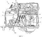
фиг.1 представляет собой поясняющий вид в поперечном разрезе, на котором изображена конструкция термопринтера согласно варианту осуществления настоящего изобретения;1 is an explanatory cross-sectional view showing a construction of a thermal printer according to an embodiment of the present invention;
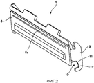
фиг.2 представляет собой вид в перспективе, на котором изображена термоголовка термопринтера согласно варианту осуществления;figure 2 is a perspective view showing a thermal head of a thermal printer according to an embodiment;
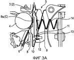
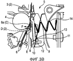
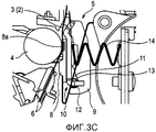
фиг.3А-3С представляют собой поясняющие виды, на которых изображена операция устранения прилипания для печатающей головки; и3A-3C are explanatory views illustrating an anti-stick operation for a print head; and
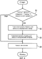
фиг.4 представляет собой блок-схему операции устранения прилипания для печатающей головки.4 is a flowchart of an anti-stick operation for a printhead.
Подробное описание вариантов осуществления настоящего изобретенияDetailed Description of Embodiments of the Present Invention
Далее в этом документе будут описаны варианты осуществления настоящего изобретения со ссылкой на чертежи. В вариантах осуществления описан термопринтер в качестве примера принтера, к которому применено настоящее изобретение.Embodiments of the present invention will be described hereinafter with reference to the drawings. In embodiments, a thermal printer is described as an example of a printer to which the present invention is applied.
(Полная конструкция принтера)(Full printer design)
Фиг.1 представляет собой поясняющий вид в поперечном разрезе, на котором изображена конструкция термопринтера согласно варианту осуществления настоящего изобретения. Термопринтер 1 (принтер) выполнен с возможностью осуществления печати во время транспортирования длинной бумаги 2 для записи (носителя записи) вдоль пути 3 транспортирования в принтере. Термопринтер 1 включает в себя опорный ролик 4, расположенный в заданном положении на пути 3 транспортирования, и термоголовку 5 (печатающую головку), расположенную так, чтобы быть обращенной к опорному ролику 4. Вход 1а бумаги предусмотрен у нижней поверхности термопринтера 1. Бумага 2 для записи, подаваемая в термопринтер 1 через вход 1а бумаги, загружается так, чтобы проходить через положение между термоголовкой 5 и опорным роликом 4. Выход 1b бумаги предусмотрен у верхней части термоголовки 5 и опорного ролика 4, и бумага 2 для записи, на которую осуществляется печать, выпускается через выход 1b бумаги наружу термопринтера 5. В качестве бумаги 2 для записи может быть использована длинная термобумага или этикеточная бумага, выполненная так, что этикетки из термобумаги приклеены к длинной основной бумаге.1 is an explanatory cross-sectional view showing a construction of a thermal printer according to an embodiment of the present invention. The thermal printer 1 (printer) is configured to print while transporting long recording paper 2 (recording medium) along the
Элемент 6 направления бумаги (направляющий элемент) для направления бумаги 2 для записи предусмотрен у стороны вверх по потоку пути транспортирования бумаги между входом 1а бумаги и положением Р зажимания термоголовки 5 и опорного ролика 4. В варианте осуществления вход 1а бумаги расположен в положении, которое слегка отклонено к опорному ролику 4 (левая сторона на фиг.1) от положения сразу под положением Р зажимания бумаги 2 для записи термоголовкой 5 и опорным роликом 4. Следовательно, путь направления в элементе 6 направления бумаги простирается диагонально к положению Р зажимания, которое расположено у правой верхней стороны относительно входа 1а бумаги. Бумага 2 для записи, которая проходит через элемент 6 направления бумаги, поворачивается опорным роликом 4 в направлении вверх.A paper guiding member 6 (guide member) for guiding the
Поворачивающая движущая сила транспортирующего двигателя 7 передается к опорному ролику 4 через передающий механизм (не изображен), такой как шестерни или подобное. Когда опорный ролик 4 поворачивается в направлении вперед (направление стрелки А на фиг.1), бумага 2 для записи транспортируется в направлении вперед к выходу 1b бумаги в связи с вращением. Когда опорный ролик 4 поворачивается в направлении назад (направление, противоположное стрелке А на фиг.1), бумага 2 для записи транспортируется обратно к входу 1а бумаги. Здесь, в описании, направления транспортирования (направление транспортирования носителя 2 записи во время печати: направление стрелки В на фиг.1) бумаги 2 для записи от входа 1а бумаги к выходу 1b бумаги называется «исходным направлением транспортирования».The turning driving force of the conveying
(Печатающая головка и ее поддерживающий механизм)(Printhead and its support mechanism)
Фиг.2 представляет собой вид в перспективе, на котором изображена термоголовка. Как показано на фиг.1 и 2, термоголовка 5 включает в себя часть 8 корпуса головки, которая обращена к опорному ролику 4, и поддерживающую раму 9, которая расположена у задней стороны части 8 корпуса головки. Поддерживающая рама 9 простирается в вертикальном направлении. Нагревающая секция 8а для нагревания бумаги 2 для записи и осуществления печати на бумаге 2 для записи предусмотрена на части 8 корпуса головки у части рядом с ее верхним концом. При осуществлении печати с термоголовкой 5 нагревающая секция 8а части 8 корпуса головки направлена к опорному ролику 4, и бумага 2 для записи зажата между нагревающей секцией 8а и опорным роликом 4.Figure 2 is a perspective view showing a thermal head. As shown in figures 1 and 2, the
Поддерживающая рама 9 образована с частью 10 с выемкой у части, простирающейся к низу части 8 корпуса головки, то есть у части, простирающейся к стороне вверх по потоку нагревающей секции 8а в исходном направлении транспортирования. Часть 10 с выемкой открыта к стороне, с которой предусмотрен путь 3 транспортирования. Часть 10 с выемкой образована неглубокой у стороны рядом с частью 8 корпуса головки, сдавленной опорным роликом 4, то есть у стороны рядом с нагревающей секцией 8а, и образована глубокой у стороны вдалеке от нагревающей секции 8а. Имеющая форму прямой линии направляющая поверхность 11 предусмотрена у низа части 10 с выемкой, и имеющая криволинейную форму поверхность 12 поддерживания вращения непрерывно образована у нижнего конца направляющей поверхности 11. Здесь направляющая поверхность 11 простирается наклонно относительно части 8 корпуса головки. Направление наклонения направляющей поверхности 8 является направлением отступания в заднюю поверхность (правая сторона на фиг.1) части 8 корпуса головки к поверхности 12 поддерживания вращения (нижняя сторона на фиг.1).The supporting
Когда термоголовка 5 расположена так, что часть 8 корпуса головки обращена к опорному ролику 4, вращающийся вал 13, поддерживаемый рамой корпуса термопринтера 1, направлен к отверстию части 10 с выемкой. Вращающийся вал 13 предусмотрен параллельно линии оси вращения опорного ролика 4. Термоголовка 5 поджимается к опорному ролику 4 давящей на головку пружиной 14 (поджимающим элементом), предусмотренной у задней поверхности части 8 корпуса головки. Поджимающей силой давящей на головку пружины 14 часть 8 корпуса головки прижимается к опорному ролику 4, и вращающийся вал 13 прижимается к внутренней поверхности части 10 с выемкой.When the
Как видно из фиг.1, когда нагревающая секция 8а направлена к опорному ролику 4, вращающийся вал 13 расположен у нижнего конца части 10 с выемкой, чтобы быть вписанным в поверхность 12 поддерживания вращения. В это время поверхность 12 поддерживания вращения может осуществить скольжение на наружную окружную поверхность вращающегося вала 13, чтобы вращать термоголовку 5. То есть термоголовка 5 поддерживается так, что термоголовка 5 обладает возможностью вращения вокруг вращающегося вала 13.As can be seen from FIG. 1, when the
К тому же, когда термоголовка 5 тянется к стороне вверх по потоку или к стороне вниз по потоку в исходном направлении транспортирования бумаги 2 для записи (в направлении вниз или в направлении вверх на фиг.1), вращающийся вал 13 скользит вдоль направляющей поверхности 11, так что вращающийся вал 13 направляет и перемещает термоголовку 5 в направлении, соответствующем направлению вытягивания, тогда как вращающийся вал 13 поддерживает термоголовку 5 против поджимающей силы давящей на головку пружины 14. С вращающимся валом 13 и направляющей поверхностью 11 термоголовка 5 поддерживается так, чтобы быть перемещаемой относительно вращающегося вала 13 в диапазоне длины направляющей поверхности 11.In addition, when the
(Операция устранения прилипания бумаги для записи)(Operation for removing sticky recording paper)
Фиг.3А, 3В и 3С представляют собой поясняющие виды, на которых проиллюстрирована работа бумаги для записи на печатающей головке. На фиг.3А изображено состояние, в котором происходит прилипание между печатающей головкой и бумагой для записи, на фиг.3В изображено состояние, в котором печатающая головка перемещена так, чтобы позволить прилипшей части быть освобожденной от давления, и на фиг.3С изображено состояние, в котором печатающая головка возвращена в ее исходное положение после устранения прилипания.3A, 3B and 3C are explanatory views illustrating the operation of recording paper on a print head. FIG. 3A shows a state in which adhesion occurs between the print head and the recording paper, FIG. 3B shows a state in which the print head is moved so as to allow the adhered part to be released from pressure, and FIG. 3C shows the state in which the print head is returned to its original position after removing adhesion.
В варианте осуществления, как видно из фиг.1 и 3А, когда осуществляется печать на бумаге 2 для записи, термоголовка 5 расположена в положении, в котором вращающийся вал 13 вписан в поверхность 12 поддерживания вращения, и нагревающая секция 8а направлена к части опорного ролика 4, наиболее выступающей к термоголовке 5. Термоголовка 5 поджимается давящей на головку пружиной 14 в направлении вращения вперед опорного ролика 4 вокруг вращающегося вала 13, и нагревающая секция 8а прижимается к опорному ролику 4 в состоянии, в котором бумага 2 для записи зажата между нагревающей секцией 8а и опорным роликом 4. В состоянии ожидания печати термопринтера 1 сохраняется описанное выше состояние. Следовательно, когда состояние ожидания печати сохраняется долго, бумага 2 для записи, прижатая к области С прижима, находящейся в центре нагревающей секции 8а, может прилипнуть к области С прижима посредством прижимающей силы.In an embodiment, as can be seen from FIGS. 1 and 3A, when printing on
Фиг.4 представляет собой блок-схему операции устранения прилипания. Когда управляющая секция термопринтера 1 получает команду выполнения операции, включающей в себя транспортирование бумаги 2 для записи, такую как команда начала печати, определяется, превышает ли в это время период Т времени ожидания (длительность состояния ожидания печати) заданный период Т0 ограниченного времени (этап S1). Если состояние ожидания печати продолжается в течение периода времени, более длинного, чем период Т0 ограниченного времени (этап S1: Да), процесс переходит на этап S2. С другой стороны, если период Т1 времени ожидания равен или меньше, чем период Т0 ограниченного времени (этап S1: Нет), процессы этапов S2-S3 пропускаются, процесс переходит на этап S4, и затем начинается намеченная операция, такая как операция печати.4 is a flowchart of an anti-sticking operation. When the control section of the
Управляющая секция термопринтера 1 осуществляет операцию транспортирования для транспортирования бумаги 2 для записи на заданную величину в направлении, противоположном исходному направлению транспортирования на этапе S2. Например, для транспортирования бумаги 2 для записи в направлении назад на величину транспортирования, соответствующую длине 24 точек из печатных точек, образованных термоголовкой 5, опорный ролик 5 вращается в направлении назад на величину вращения, соответствующую транспортированию назад опорного ролика на 24 точки. В этой операции транспортирующая сила, направленная к стороне вверх по потоку в исходном направлении транспортирования, действует на часть бумаги 2 для записи, прилипшей к области С прижима так, что термоголовка 5 тянется к стороне вверх по потоку в исходном направлении транспортирования через бумагу 2 для записи.The control section of the
Поскольку вращающийся вал 13 обладает возможностью скольжения вдоль направляющей поверхности 11, термоголовка 5 поддерживается так, чтобы быть перемещаемой относительно опорного ролика 4. Когда термоголовка 5 тянется к стороне вверх по потоку через бумагу 2 для записи, прилипшую к области С прижима, вращающийся вал 13 скользит вдоль направляющей поверхности 11 так, что термоголовка 5 в целом перемещается к той же стороне, что и направление вытягивания. Когда термоголовка 5 перемещается относительно опорного ролика 4, положение прижима сдвигается от области С прижима к стороне вниз по потоку в исходном направлении транспортирования. Как видно из фиг.3В, количество транспортирования назад на этапе S2 является количеством транспортирования, на которое может быть перемещена термоголовка 5 до тех пор, пока область С прижима не будет полностью удалена от положения сдавливания опорным роликом 4. Следовательно, посредством осуществления процесса этапа S2 область С прижима перемещается к стороне вверх по потоку так, чтобы быть полностью освобожденной от давления.Since the
К тому же, при перемещении термоголовки 5 на этапе S2 ее перемещение ограничено опорным роликом 4, к которому прижата верхняя часть части 8 корпуса головки, и вращающимся валом 13, который прижат к направляющей поверхности 11. Благодаря этому ограничению термоголовка 5 не перемещается в точно таком же направлении, как толкающая сила. Термоголовка 5 перемещается в направлении диагонально ниже направо, параллельно направляющей поверхности 11, тогда как термоголовка 5 в целом слегка поворачивается в направлении, в котором ее верхняя часть наклонена к опорному ролику 4 (в направлении против часовой стрелки на фиг.3В). Следовательно, область С прижима перемещена в положение вне обычного пути 3 транспортирования, и бумага 2 для записи, прилипшая к области С прижима, также перемещена в положение вне обычного пути 3 транспортирования. Соответственно, бумага 2 для записи занимает такое положение, что бумага для записи диагонально поднимается от поверхности головки так, чтобы иметь заданный угол Е подъема у стороны вверх по потоку области С прижима, так что на нее действует сила, отслаивающая и поднимающая бумагу 2 для записи от области С прижима (сила, действующая в направлении F на фиг.3В). Следовательно, бумага 2 для записи может быть отслоена более легко, чем в обычном способе отслаивания посредством сдвигающей силы.In addition, when moving the
К тому же, в варианте осуществления элемент 6 направления бумаги, простирающийся к положению рядом с опорным роликом 4, предусмотрен у стороны вверх по потоку в пути 3 транспортирования, чтобы направлять бумагу 2 для записи. Таким образом, когда область С прижима перемещается к положению вне обычного пути 3 транспортирования, бумага 2 для записи провисает вдоль пути D сгибания, обозначенного пунктирной линией на фиг.3В, на коротком интервале от элемента 6 направления бумаги до области С прижима. Это состояние провисания является состоянием провисания, в котором угол Е подъема является большим в части, в которой бумага 2 для записи поднимается от поверхности головки, и состоянием провисания, в котором сила, отслаивающая и поднимающая бумагу 2 для записи от области С прижима, является большой. То есть посредством образования этого состояния провисания бумага 2 для записи может быть отслоена более успешно. Поскольку угол Е подъема бумаги 2 для записи постепенно увеличивается в процессе перемещения термоголовки 5 от состояния, изображенного на фиг.3А, в состояние, изображенное на фиг.3В, сила, отслаивающая и поднимающая бумагу 2 для записи, постепенно увеличивается. Соответственно, бумага 2 для записи может быть отслоена плавно.In addition, in an embodiment, the
Тем временем, в случае если элемент 6 направления бумаги не присутствует, путь бумаги 2 для записи у стороны вверх по потоку не ограничен, так что бумага 2 для записи может аккуратно провисать с большой кривизной. Следовательно, угол Е подъема бумаги 2 для записи не становится большим. Тем не менее, поскольку приложена отслаивающая и поднимающая сила, возможно отслаивать бумагу 2 для записи более легко, чем в обычном способе отслаивания посредством сдвигающей силы. К тому же, даже если цель перемещения области С прижима не намного сдвинута от обычного пути 3 транспортирования, изгибание бумаги 2 для записи образуется посредством транспортирования назад, так что на нее действует отслаивающая и поднимающая сила, несмотря на то что она не является такой большой, как в упомянутом выше случае. Соответственно, возможно отслаивать бумагу 2 для записи более легко, чем в обычном способе отслаивания только посредством сдвигающей силы.Meanwhile, in the event that the
Процесс управляющей секции термопринтера 1 переходит на этап S3 после завершения операции на этапе S2, и бумага для записи транспортируется в направлении вперед (в исходном направлении транспортирования) на такую же величину транспортирования, как величина транспортирования назад на этапе S2. Например, опорный ролик 4 поворачивается вперед на величину поворота, соответствующую транспортированию вперед на 24 точки. В этой операции, как видно из фиг.3С, бумага 2 для записи возвращается в положение перед состоянием ожидания, и положение начала печати бумаги 2 для записи располагается у положения Р зажимания опорного ролика 4. К тому же, термоголовка 5, прижатая к бумаге 2 для записи, транспортируемой в исходном направлении транспортирования, тянется к стороне вниз по потоку вместе с бумагой 2 для записи, так что термоголовка 5 перемещается назад по пути перемещения, по которому она перемещалась на этапе S2, и бумага 2 для записи зажимается между нагревающей секцией 8а и опорным роликом 4. Тем временем, в это время, поскольку направляющая поверхность 11 наклонена, поджимающая сила давящей на головку пружины 14 действует в качестве силы, сдвигающей полностью термоголовку 5 к диагонально левой верхней стороне вдоль направления направляющей поверхности 11. При упомянутом выше, когда термоголовка 5 возвращена, процесс переходит на этап S4, и начинается намеченная операция, такая как операция печати.The process of the control section of the
Таким образом, термопринтер 1 варианта осуществления включает в себя поддерживающий механизм для термоголовки 5, который может прилагать силу, отслаивающую и поднимающую бумагу 2 для записи, прилипшую к части 8 корпуса головки, посредством освобождения бумаги 2 для записи от давления опорного ролика 4. С упомянутой выше конфигурацией возможно легко и надежно устранять прилипание. К тому же, операция устранения прилипания, которая выполнена с возможностью перемещать термоголовку в диапазоне перемещения термоголовки 5 посредством поддерживающего механизма, может быть осуществлена только посредством поворотов вперед и назад опорного ролика 4. Следовательно, нет необходимости в предусматривании заново движущей силы, перемещающей термоголовку, и устранение прилипания может быть достигнуто с малыми затратами.Thus, the
(Примеры модификаций)(Examples of modifications)
(1) В упомянутом выше варианте осуществления несмотря на то что положение прижима опорного ролика 4 сдвинуто посредством транспортирования бумаги 2 для записи к стороне вверх по потоку в исходном направлении транспортирования, также возможно освобождать прилипшую часть от давления посредством транспортирования бумаги 2 для записи к стороне вниз по потоку в исходном направлении транспортирования. Например, достаточно переставить термоголовку 5 и вращающийся вал посредством обращения их вертикальной ориентации на фиг.1 относительно положения прижима опорного ролика 4. С этой конфигурацией возможно устранить прилипание посредством транспортирования в исходном направлении транспортирования. К тому же, в это время посредством предусматривания элемента направления бумаги у части спереди выхода 1b бумаги возможно положительно прилагать силу, отслаивающую и поднимающую бумагу 2 для записи, подобно элементу 6 направления бумаги в упомянутом выше варианте осуществления.(1) In the above embodiment, although the press position of the
(2) Несмотря на то что операция транспортирования назад и операция транспортирования в направлении вперед осуществляются один раз в упомянутом выше варианте осуществления, соответственно, как и операция устранения прилипания, операция транспортирования назад и операция транспортирования в направлении вперед могут осуществляться множество раз. С этим возможно надежно отслаивать сильно прилипшую бумагу 2 для записи.(2) Although the backward transport operation and the forward transport operation are performed once in the above embodiment, respectively, like the non-sticking operation, the backward transport operation and the transport operation in the forward direction can be performed multiple times. With this, it is possible to reliably peel off the strongly adhered
(3) Несмотря на то что в упомянутом выше варианте осуществления предусмотрена часть 10 с выемкой, открытая к пути 3 транспортирования, и направляющая поверхность 11 для сдвигания вращающегося вала 13 предусмотрена у ее нижней части, возможно, чтобы продолговатое отверстие, простирающееся в таком же направлении, что и направляющая поверхность 11, было образовано вместо части 10 с выемкой, и вращающийся вал 13 был прикреплен к продолговатому отверстию.(3) Despite the fact that in the above embodiment, a
(4) Для обеспечения возвращения термоголовки 5 на этапе S3 в упомянутом выше варианте осуществления возможно предусмотреть поджимающий элемент или подобное для вытягивания вверх термоголовки 5 (сторона вниз по потоку в исходном направлении транспортирования).(4) In order to ensure the return of the
(5) Несмотря на то что в упомянутом выше варианте осуществления бумага 2 для записи прилипает к термоголовке 5, в основном, у нагревающей секции 8а, положение прилипания (положение зажимания бумаги 2 для записи) не ограничено частью, где предусмотрена нагревающая секция 8а.(5) Although in the above embodiment, the
(6) Несмотря на то что в упомянутом выше варианте осуществления изобретение применено к термопринтеру 1, изобретение может быть применено к другому принтеру. То есть изобретение может быть применено к любому принтеру, в котором носитель записи зажимается между опорным роликом и печатающей головкой и сдавлен посредством этого, и носитель записи может прилипнуть к печатающей головке, когда носитель записи остается в этом прижатом состоянии во время ожидания печати. К тому же, изобретение может быть применено к принтеру, который осуществляет печать на носителе записи, таком как бумага с покрывающим слоем на ее печатной поверхности, или этикеточная бумага.(6) Although in the above embodiment, the invention is applied to
(7) Несмотря на то что термоголовка 7 тянется и перемещается посредством транспортирующей силы для транспортирования бумаги 2 для записи, возможно, чтобы термоголовка 5 перемещалась посредством источника движения, отличающегося от транспортирующего узла бумаги 2 для записи, чтобы сдвигать место контакта с опорным роликом 4. Источник движения, отличающийся от транспортирующего узла бумаги 2 для записи, может способствовать крутящему моменту опорного ролика 4.(7) Although the
(8) Несмотря на то что в конфигурации термопринтера 1 согласно упомянутому выше изобретению часть 8 корпуса головки, которая контактирует с опорным роликом 4, имеет поверхность, параллельную вертикальной поверхности, изобретение не ограничено этим расположением. Часть 8 корпуса головки может быть наклонена относительно вертикальной поверхности и контактировать с опорным роликом 4. Даже если часть 8 корпуса головки контактирует с опорным роликом 4 таким образом, преимущественные эффекты упомянутого выше изобретения могут быть достигнуты посредством расположения входа 1а бумаги и элемента 6 направления бумаги у стороны опорного ролика 4 относительно вертикальной поверхности, проходящей через центр области С прижима (разрезанной области части 8 корпуса головки на фиг.3А-3С), которая является областью зажимания между опорным роликом 4 и частью 8 корпуса головки, в направлении транспортирования носителя записи. То есть вход 1а бумаги и элемент 6 направления бумаги расположены у стороны опорного ролика 4 относительно виртуальной поверхности, включающей в себя касательную линию опорного ролика 4, которая проходит через центр области С прижима в направлении транспортирования бумаги 2 для записи. Следовательно, бумага 2 для записи может быть обмотана вокруг опорного ролика 4. К тому же, посредством простирания направляющей поверхности 11, образованной в поддерживающей раме 9, которая образует поддерживающий механизм, в направлении от виртуальной поверхности, направляющая поверхность 11 сдвигается вдоль вращающегося вала 13, предусмотренного в термопринтере 1, и поддерживающая рама 9 перемещается. Благодаря перемещению поддерживающей рамы 9 часть 8 корпуса головки, которая поддерживается поддерживающей рамой 9, также перемещается, и область С прижима части 8 корпуса головки сдвигается к положению, в котором прижимающая сила снимается. В это время вращающийся вал 13 расположен у стороны части 8 корпуса головки относительно виртуальной поверхности.(8) Despite the fact that in the configuration of the
(9) Секция управления термопринтера 1 согласно упомянутому выше варианту осуществления осуществляет управление поворотом опорного ролика 4 на величину поворота, соответствующую транспортированию назад на 24 печатные точки, образованные термоголовкой 5 на этапе S2. 24 печатные точки, образованные термоголовкой 5, соответствуют расстоянию, достаточно большему, чем направление перемещения, соответствующее области С прижима. Настоящее изобретение не ограничено упомянутой выше операцией. Длина L области С прижима в направлении транспортирования бумаги для записи в варианте осуществления соответствует, примерно, 10-12 печатным точкам, несмотря на то что она изменяется в зависимости от прижимающей силы части 8 корпуса головки и опорного ролика 4 и твердости опорного ролика 4.(9) The control section of the
Конфигурация упомянутых выше вариантов осуществления предназначена для предотвращения прилипания бумаги 2 для записи к термоголовке 5. Для устранения прилипания, возникающего из-за нагревающей секции 8а, которая является печатающей частью термоголовки 5, осуществляется следующая операция. В случае если операция устранения прилипания осуществляется посредством перемещения термоголовки 5 вверх по потоку в направлении транспортирования бумаги для записи, термоголовка 5 (то есть часть 8 корпуса головки) перемещается на расстояние, равное или большее, чем расстояние L1(<L), от конца вверх по потоку области С прижима в направлении транспортирования бумаги для записи к нагревающей области 8а. С другой стороны, в случае если операция устранения прилипания осуществляется посредством перемещения термоголовки 5 вниз по потоку в направлении транспортирования бумаги для записи, термоголовка 5 (то есть часть 8 корпуса головки) перемещается на расстояние, равное или большее, чем расстояние L2(<L), от конца вниз по потоку области С прижима в направлении транспортирования бумаги для записи к нагревающей области 8а. Если нагревающая секция 8а расположена у центра области С прижима, L1 равна L2 и равна 1/2L. Посредством перемещения термоголовки 5 на расстояние от концевой части области С прижима у стороны направления перемещения термоголовки 5 к нагревающей секции 8а прилипание, возникающее из-за нагревающей секции 8а, может быть исключено.The configuration of the above embodiments is intended to prevent sticking of the
Для устранения прилипания, возникающего из-за прижимающей силы области С прижима термоголовка 5 перемещается, по меньшей мере, на расстояние L области С прижима в направлении транспортирования бумаги для записи или больше. Это приводит к снятию прижимающей силы, действующей на бумагу 2 для записи у положения, соответствующего области С прижима, к которой приложена прижимающая сила во время состояния ожидания печати, и, таким образом, прилипание может быть исключено.In order to eliminate adhesion due to the pressing force of the pressing region C, the
(10) В упомянутом выше варианте осуществления сила, отслаивающая и поднимающая бумагу 2 для печати, действует, даже если элемент 6 направления бумаги отсутствует. Это происходит потому, что когда термоголовка 5 перемещается вверх по потоку в направлении транспортирования бумаги 2 для записи, бумага 2 для записи в положении, отличающемся от положения, соответствующего области С прижима, поддерживается прижимающей силой части 8 корпуса головки и опорного ролика 4 у стороны вниз по потоку бумаги 2 для записи в направлении транспортирования бумаги 2 для записи. С другой стороны, у стороны вверх по потоку бумаги 2 для записи в направлении транспортирования бумаги 2 для записи конец вверх по потоку бумаги 2 для записи поддерживается входом 1а бумаги или рулоном, если в качестве бумаги 2 для записи используется бумага в рулоне. Поскольку конец вверх по потоку бумаги 2 для записи поддерживается в положении, удаленном от термоголовки 5 по сравнению с элементом 6 направления бумаги, отслаивающая и поднимающая сила не является такой сильной, но сила действует на бумагу 2 для записи.(10) In the aforementioned embodiment, the force exfoliating and lifting the
(11) Период Т времени ожидания (длительность состояния ожидания печати) соответствует периоду времени от времени, когда бумага 2 для записи останавливается у положения зажимания (области прижима во время ожидания печати), до времени получения команды начала печати, включающего в себя операцию транспортирования бумаги 2 для записи. В частности, период Т времени ожидания соответствует периоду времени от времени, когда операция печати заканчивается, и опорный ролик 4 останавливается в состоянии, в котором часть 8 корпуса головки прижата к опорному ролику 4, до времени получения следующей команды печати. Этот период времени измеряется хронометром (хронометрирующим средством), который не показан, и период Т времени ожидания получается из измеренной информации. Даже если электроэнергия отключается в состоянии, в котором опорный ролик 4 остановлен, хронометр измеряет время как период времени ожидания, пока продолжается состояние, в котором опорный ролик 4 придавлен к части 8 корпуса головки.(11) The waiting time period T (the duration of the printing standby state) corresponds to the period from the time when the
(12) В упомянутом выше варианте осуществления, когда операция на этапе S2 завершена, операция переходит на этап S3 для транспортирования бумаги 2 для записи в направлении вперед на такую же величину транспортирования, что и величина транспортирования назад на этапе S2. Настоящее изобретение не ограничено этой операцией. Например, для предотвращения печати на бумаге 2 для записи, расположенной у области С прижима во время ожидания печати, возможно транспортировать бумагу 2 для записи на расстояние, большее чем величина транспортирования назад. Для предотвращения печати на всей области бумаги 2 для записи, расположенной у области С прижима во время ожидания печати, возможно перемещать бумагу 2 для печати на величину, полученную посредством сложения расстояния области С прижима в направлении транспортирования бумаги 2 для записи с величиной транспортирования назад, или больше.(12) In the above embodiment, when the operation in step S2 is completed, the operation proceeds to step S3 for transporting the
Claims (8)
часть корпуса головки, имеющую печатающую часть, которая осуществляет печать на носителе записи и обращена к опорному ролику, выполненному с возможностью транспортирования носителя записи; и
поддерживающий механизм, который поддерживает печатающую головку, прижимает печатающую головку к опорному ролику и позволяет опорному ролику перемещать часть корпуса головки в таком направлении, чтобы место контакта части корпуса головки относительно опорного ролика смещалась, при этом сохраняя часть корпуса головки прижатой к опорному ролику.1. A print head containing:
a head housing part having a printing part that prints on the recording medium and faces a support roller configured to transport the recording medium; and
a supporting mechanism that supports the print head presses the print head against the support roller and allows the support roller to move part of the head housing in such a way that the contact point of the part of the head housing relative to the support roller moves while keeping the part of the head housing pressed against the support roller.
причем поверхность поддерживания вращения направляющей поверхности прижата к вращающемуся валу посредством контакта между частью корпуса головки и опорным роликом, причем вращающийся вал перемещается относительно и вдоль направляющей поверхности так, чтобы перемещать место контакта части корпуса головки относительно опорного ролика, и поддерживающий механизм поворачивается вокруг вращающегося вала и поверхности поддерживания вращения так, чтобы перемещать место контакта части корпуса головки относительно опорного ролика.3. The print head according to claim 1, in which the supporting mechanism includes a surface for maintaining rotation, which is in contact with a rotating shaft that is parallel to the axis of rotation of the support roller, and a guide surface that is continuous with the surface for supporting rotation and which extends to the side contact points of the head housing relative to the support roller,
moreover, the surface for supporting the rotation of the guide surface is pressed against the rotating shaft by the contact between the part of the head housing and the support roller, and the rotating shaft is moved relative to and along the guide surface so as to move the contact point of the part of the head housing relative to the support roller, and the support mechanism is rotated around the rotating shaft and surfaces to maintain rotation so as to move the contact point of the part of the head housing relative to the support roller.
опорный ролик, выполненный с возможностью транспортирования носителя записи;
печатающую головку, которая имеет часть корпуса головки, имеющую печатающую часть, которая осуществляет печать на носителе записи и обращена к опорному ролику;
поджимающий элемент, который поджимает печатающую головку к опорному ролику; и
поддерживающий механизм, который поддерживает печатающую головку, прижимает печатающую головку к опорному ролику и позволяет опорному ролику перемещать часть корпуса головки в таком направлении, чтобы место контакта части корпуса головки относительно опорного ролика смещалась, при этом сохраняя часть корпуса головки прижатой к опорному ролику.5. A printer containing:
a support roller configured to transport the recording medium;
a print head, which has a part of the head housing having a print part, which prints on a recording medium and faces the support roller;
a pressing member that presses the print head against the support roller; and
a supporting mechanism that supports the print head presses the print head against the support roller and allows the support roller to move part of the head housing in such a way that the contact point of the part of the head housing relative to the support roller moves while keeping the part of the head housing pressed against the support roller.
путь транспортирования, транспортирующий носитель записи к месту контакта между опорным роликом и частью корпуса головки; и
направляющий элемент, расположенный на пути транспортирования у той же стороны, что и направление, в котором перемещается часть корпуса головки относительно опорного ролика, и выполненный с возможностью направления носителя записи.6. The printer according to claim 5, further comprising:
a transportation path transporting the recording medium to a point of contact between the support roller and a part of the head housing; and
a guide element located on the transport path on the same side as the direction in which part of the head housing moves relative to the support roller, and configured to direct the recording medium.
получение команды выполнения операции, включающей в себя транспортирование носителя записи;
подсчет длительности состояния ожидания печати до тех пор, пока не будет получена команда выполнения; и
перемещение части корпуса головки печатающей головки в таком направлении, чтобы место контакта части корпуса головки относительно опорного ролика смещалось, при этом сохраняя часть корпуса головки прижатой к опорному ролику, когда длительность состояния ожидания печатания превышает заданный ограниченный период.7. A method of controlling a printer, comprising:
receiving a command to perform an operation including transporting the recording medium;
counting the duration of the print standby state until an execution command is received; and
moving the part of the head body of the print head in such a way that the contact point of the part of the head body relative to the support roller is displaced, while keeping the part of the head body pressed against the support roller when the duration of the printing waiting state exceeds a predetermined limited period.
Applications Claiming Priority (4)
| Application Number | Priority Date | Filing Date | Title |
|---|---|---|---|
| JP2010-182125 | 2010-08-17 | ||
| JP2010182125 | 2010-08-17 | ||
| JP2011-170775 | 2011-08-04 | ||
| JP2011170775A JP5821376B2 (en) | 2010-08-17 | 2011-08-04 | printer |
Related Child Applications (1)
| Application Number | Title | Priority Date | Filing Date |
|---|---|---|---|
| RU2013103086/12A Division RU2530421C2 (en) | 2010-08-17 | 2011-08-16 | Print head, printer and method of operating printer |
Publications (2)
| Publication Number | Publication Date |
|---|---|
| RU2011134387A RU2011134387A (en) | 2013-03-10 |
| RU2481195C2 true RU2481195C2 (en) | 2013-05-10 |
Family
ID=44654012
Family Applications (2)
| Application Number | Title | Priority Date | Filing Date |
|---|---|---|---|
| RU2013103086/12A RU2530421C2 (en) | 2010-08-17 | 2011-08-16 | Print head, printer and method of operating printer |
| RU2011134387/12A RU2481195C2 (en) | 2010-08-17 | 2011-08-16 | Printing head, printer and method of printer control |
Family Applications Before (1)
| Application Number | Title | Priority Date | Filing Date |
|---|---|---|---|
| RU2013103086/12A RU2530421C2 (en) | 2010-08-17 | 2011-08-16 | Print head, printer and method of operating printer |
Country Status (7)
| Country | Link |
|---|---|
| US (3) | US8446441B2 (en) |
| EP (1) | EP2420387B1 (en) |
| JP (1) | JP5821376B2 (en) |
| KR (1) | KR101926192B1 (en) |
| CN (2) | CN102416772B (en) |
| BR (1) | BRPI1106839A2 (en) |
| RU (2) | RU2530421C2 (en) |
Families Citing this family (10)
| Publication number | Priority date | Publication date | Assignee | Title |
|---|---|---|---|---|
| JP5821376B2 (en) * | 2010-08-17 | 2015-11-24 | セイコーエプソン株式会社 | printer |
| JP5739848B2 (en) * | 2012-08-03 | 2015-06-24 | 東芝テック株式会社 | Printing apparatus and printing method |
| JP6225567B2 (en) * | 2013-08-30 | 2017-11-08 | セイコーエプソン株式会社 | Print head and printing apparatus |
| CN104275948B (en) * | 2013-07-04 | 2017-07-28 | 精工爱普生株式会社 | The alignment method of printing equipment, print head and printing equipment |
| JP6372982B2 (en) * | 2013-08-28 | 2018-08-15 | 富士通コンポーネント株式会社 | Printer device |
| JP6908877B2 (en) * | 2017-02-03 | 2021-07-28 | セイコーエプソン株式会社 | Printing equipment and printing method |
| JP2019006569A (en) * | 2017-06-26 | 2019-01-17 | カシオ計算機株式会社 | Printer, printer control method, and program |
| CN107234878B (en) * | 2017-07-27 | 2019-09-27 | 厦门汉印电子技术有限公司 | A kind of driving device and its thermal printer of print head |
| JP7307894B2 (en) * | 2019-09-26 | 2023-07-13 | 大日本印刷株式会社 | THERMAL TRANSFER SYSTEM AND THERMAL TRANSFER METHOD |
| JP2023046473A (en) * | 2021-09-24 | 2023-04-05 | カシオ計算機株式会社 | Printing device and printing method |
Citations (4)
| Publication number | Priority date | Publication date | Assignee | Title |
|---|---|---|---|---|
| JPS6392465A (en) * | 1986-10-08 | 1988-04-22 | Nec Corp | Thermal transfer printer |
| US5599113A (en) * | 1994-05-18 | 1997-02-04 | Asahi Kogaku Kogyo Kabushiki Kaisha | Thermal printer |
| US20050285888A1 (en) * | 2004-06-25 | 2005-12-29 | Xerox Corporation | Systems and methods for determining printhead in a standby position |
| JP2006334858A (en) * | 2005-05-31 | 2006-12-14 | Sato Corp | Label printer and method of preventing label from sticking to thermal printing head |
Family Cites Families (23)
| Publication number | Priority date | Publication date | Assignee | Title |
|---|---|---|---|---|
| JPS6230057A (en) * | 1985-07-31 | 1987-02-09 | Canon Inc | Heat-transfer recording device |
| JP2710656B2 (en) * | 1989-02-06 | 1998-02-10 | シャープ株式会社 | Recording device |
| JPH0214394A (en) * | 1989-05-25 | 1990-01-18 | Kubota Ltd | Method for printing and note issuing in automatic vending machine |
| JPH034174A (en) | 1989-05-31 | 1991-01-10 | Nippondenso Co Ltd | Speed detecting device for vehicle |
| JPH04369961A (en) * | 1991-04-08 | 1992-12-22 | Ricoh Co Ltd | Printer and image reader |
| JPH05155100A (en) * | 1991-12-04 | 1993-06-22 | Seiko Instr Inc | Mechanism for retaining thermal head |
| JP2825716B2 (en) * | 1992-10-16 | 1998-11-18 | シャープ株式会社 | Thermal printing mechanism |
| JP3004174B2 (en) * | 1994-07-29 | 2000-01-31 | 沖電気工業株式会社 | Thermal printer |
| DE69710634D1 (en) * | 1996-05-09 | 2002-04-04 | Agfa Gevaert Nv | Thermal printing device with printhead adjustment |
| JPH09314944A (en) * | 1996-05-29 | 1997-12-09 | Seiko Epson Corp | Thermal printer |
| JP3659535B2 (en) * | 1996-09-17 | 2005-06-15 | 株式会社サトー | Head position adjustment device for thermal printer |
| JPH10157052A (en) | 1996-12-04 | 1998-06-16 | Tohoku Ricoh Co Ltd | Plate-making writing apparatus and plate-making printing apparatus |
| JP2000222536A (en) | 1999-01-28 | 2000-08-11 | Sankyo Seiki Mfg Co Ltd | Card reader and its control method |
| JP2000280499A (en) * | 1999-03-30 | 2000-10-10 | Matsushita Graphic Communication Systems Inc | Image-recording apparatus and method for recording image |
| JP4251014B2 (en) * | 2003-05-22 | 2009-04-08 | セイコーエプソン株式会社 | Printer and printer control method |
| JP4146292B2 (en) * | 2003-06-09 | 2008-09-10 | セイコーインスツル株式会社 | Printer device |
| JP2005035109A (en) * | 2003-07-17 | 2005-02-10 | Alps Electric Co Ltd | Thermal printer |
| JP4817101B2 (en) | 2005-09-12 | 2011-11-16 | セイコーインスツル株式会社 | Thermal activation device, printing device and printer |
| JP5256893B2 (en) * | 2008-07-07 | 2013-08-07 | セイコーエプソン株式会社 | RECORDING DEVICE, CONTROL METHOD AND CONTROL PROGRAM FOR RECORDING DEVICE |
| JP5155100B2 (en) * | 2008-10-27 | 2013-02-27 | パナソニック株式会社 | Tag reader device |
| JP2010182125A (en) | 2009-02-05 | 2010-08-19 | Cosmotopia Japan Inc | Learning support system |
| JP5268966B2 (en) | 2010-02-22 | 2013-08-21 | 京セラドキュメントソリューションズ株式会社 | Display control apparatus, image forming apparatus, display control method, and display control program |
| JP5821376B2 (en) * | 2010-08-17 | 2015-11-24 | セイコーエプソン株式会社 | printer |
-
2011
- 2011-08-04 JP JP2011170775A patent/JP5821376B2/en active Active
- 2011-08-16 RU RU2013103086/12A patent/RU2530421C2/en active
- 2011-08-16 US US13/210,451 patent/US8446441B2/en active Active
- 2011-08-16 RU RU2011134387/12A patent/RU2481195C2/en active
- 2011-08-16 EP EP11177703.3A patent/EP2420387B1/en active Active
- 2011-08-16 BR BRPI1106839-6A patent/BRPI1106839A2/en not_active Application Discontinuation
- 2011-08-16 KR KR1020110081350A patent/KR101926192B1/en active IP Right Grant
- 2011-08-17 CN CN201110235776.8A patent/CN102416772B/en active Active
- 2011-08-17 CN CN201510514607.6A patent/CN105109212B/en active Active
-
2013
- 2013-04-19 US US13/866,090 patent/US8654163B2/en active Active
- 2013-12-12 US US14/104,114 patent/US8803930B2/en active Active
Patent Citations (4)
| Publication number | Priority date | Publication date | Assignee | Title |
|---|---|---|---|---|
| JPS6392465A (en) * | 1986-10-08 | 1988-04-22 | Nec Corp | Thermal transfer printer |
| US5599113A (en) * | 1994-05-18 | 1997-02-04 | Asahi Kogaku Kogyo Kabushiki Kaisha | Thermal printer |
| US20050285888A1 (en) * | 2004-06-25 | 2005-12-29 | Xerox Corporation | Systems and methods for determining printhead in a standby position |
| JP2006334858A (en) * | 2005-05-31 | 2006-12-14 | Sato Corp | Label printer and method of preventing label from sticking to thermal printing head |
Also Published As
| Publication number | Publication date |
|---|---|
| CN105109212A (en) | 2015-12-02 |
| JP5821376B2 (en) | 2015-11-24 |
| BRPI1106839A2 (en) | 2013-03-26 |
| US20140098173A1 (en) | 2014-04-10 |
| US8803930B2 (en) | 2014-08-12 |
| EP2420387A1 (en) | 2012-02-22 |
| US8654163B2 (en) | 2014-02-18 |
| US20120044313A1 (en) | 2012-02-23 |
| RU2011134387A (en) | 2013-03-10 |
| EP2420387B1 (en) | 2015-03-25 |
| CN105109212B (en) | 2017-06-09 |
| KR101926192B1 (en) | 2018-12-06 |
| JP2012061848A (en) | 2012-03-29 |
| CN102416772B (en) | 2015-09-23 |
| US20130229480A1 (en) | 2013-09-05 |
| RU2013103086A (en) | 2014-07-27 |
| US8446441B2 (en) | 2013-05-21 |
| KR20120017007A (en) | 2012-02-27 |
| RU2530421C2 (en) | 2014-10-10 |
| CN102416772A (en) | 2012-04-18 |
Similar Documents
| Publication | Publication Date | Title |
|---|---|---|
| RU2481195C2 (en) | Printing head, printer and method of printer control | |
| JP5039805B2 (en) | Label printer | |
| JP5769466B2 (en) | Adhesive label issuing device and printer | |
| JP2011207074A5 (en) | ||
| WO2017097017A1 (en) | Method for controlling label printer, and label printer | |
| JP2004315197A (en) | Double-sided recording device | |
| JP4594697B2 (en) | Label peeling method for label paper and label printer | |
| US6664993B2 (en) | Image transfer apparatus and image transfer method | |
| JP2011037111A (en) | Method for manufacturing transfer medium, transfer method, transfer medium manufacturing apparatus, and transfer device | |
| JP4932537B2 (en) | Decal device | |
| JP5613703B2 (en) | Label peeling device | |
| JP6878780B2 (en) | Peeling device and inkjet printer | |
| JP2010089378A (en) | Thermal printer | |
| JP3017795B2 (en) | Booklet printing apparatus and printing method for booklet | |
| JP2752926B2 (en) | Printer media holding device | |
| JP2012206369A (en) | Printer and control method thereof | |
| JP5888398B2 (en) | Recording device | |
| JP2001315366A (en) | Undercoat thermal transfer method and thermal transfer printer | |
| JPH08258355A (en) | Sheet feeding mechanism for printer | |
| JPS61237673A (en) | Thermal transfer recorder | |
| JP2005247434A (en) | Feeding device, recording device equipped with it, liquid jetting device, and feeding method | |
| JP2006181732A (en) | Intermediate transfer type thermal transfer printing apparatus and method for releasing its film | |
| JP2000211764A (en) | Thermal transfer recording device | |
| JP2005205644A (en) | Stencil printer | |
| JPS60155484A (en) | Thermal transfer printer |