JP6225567B2 - Print head and printing apparatus - Google Patents
Print head and printing apparatus Download PDFInfo
- Publication number
- JP6225567B2 JP6225567B2 JP2013180017A JP2013180017A JP6225567B2 JP 6225567 B2 JP6225567 B2 JP 6225567B2 JP 2013180017 A JP2013180017 A JP 2013180017A JP 2013180017 A JP2013180017 A JP 2013180017A JP 6225567 B2 JP6225567 B2 JP 6225567B2
- Authority
- JP
- Japan
- Prior art keywords
- main body
- head main
- platen roller
- recording medium
- head
- Prior art date
- Legal status (The legal status is an assumption and is not a legal conclusion. Google has not performed a legal analysis and makes no representation as to the accuracy of the status listed.)
- Expired - Fee Related
Links
Images


Landscapes
- Electronic Switches (AREA)
Description
本発明は、記録媒体を印刷ヘッドとプラテンローラーの間に挟んで押圧状態にして、プラテンローラーを回転駆動することにより記録媒体を搬送しながら印刷する印刷装置及びその印刷ヘッドに関する。 The present invention relates to a printing apparatus that prints while conveying a recording medium by putting the recording medium between a printing head and a platen roller to be in a pressed state and rotationally driving the platen roller, and the printing head.
一般に、印刷ヘッドに対してプラテンローラーを対向配置し、印刷ヘッドとプラテンローラーとの間に記録媒体を挟み込んで搬送しながら印刷するプリンター(印刷装置)が知られている。この種のプリンターでは、印刷ヘッドとプラテンローラーとの間に記録媒体が挟まれた状態で待機状態に入り、印刷ヘッドに記録媒体が押し付けられた状態のまま、長時間が経過してしまうことがある。このため、例えば、印刷面にコーティングが施された記録媒体等といった押圧すると貼り付きやすい記録媒体に印刷すると、待機状態で長時間放置された場合に、印刷ヘッドに記録媒体が貼り付いてしまうことがある。
この問題を解決するために、従来、プラテンローラーに印刷ヘッドを押圧した状態で前記プラテンローラーと当接する位置を変化させる方向に印刷ヘッドを移動させることにより、印刷ヘッドに貼り付いた記録媒体を剥がすことができるものが提案されている(例えば、特許文献1参照)。
In general, a printer (printing apparatus) is known in which a platen roller is disposed so as to face a print head, and printing is performed while a recording medium is sandwiched and conveyed between the print head and the platen roller. In this type of printer, a standby state may be entered with a recording medium sandwiched between the print head and the platen roller, and a long time may elapse while the recording medium is pressed against the print head. is there. For this reason, for example, when printing on a recording medium that is easy to stick when pressed, such as a recording medium with a coating on the printing surface, the recording medium sticks to the print head when left in a standby state for a long time. There is.
In order to solve this problem, the recording medium attached to the print head is peeled off by moving the print head in a direction that changes the position of contact with the platen roller while the print head is pressed against the platen roller. The thing which can do is proposed (for example, refer patent document 1).
しかしながら、特許文献1の印刷ヘッドは、ヘッド本体部を固定する支持フレームを備え、この支持フレームは、筐体の両側板の内面にそれぞれ形成された突起によって、移動した際の位置が規制される。印刷ヘッドに、例えば、位置公差やヘッド本体部の捻じれ等の部品ばらつきが生じると、該印刷ヘッドをプラテンローラーに押圧したとしても、上記突起によって印刷ヘッドの移動が規制され該押圧が不均一となり、印字品質の低下もしくは紙送りスキューが生じるといった問題があった。 However, the print head of Patent Document 1 includes a support frame that fixes the head main body, and the position of the support frame when it is moved is regulated by protrusions formed on the inner surfaces of both side plates of the housing. . For example, if the print head is subject to component variations such as positional tolerance or twisting of the head main body, even if the print head is pressed against the platen roller, the movement of the print head is restricted by the protrusions and the press is uneven. As a result, there has been a problem that print quality is lowered or paper feed skew occurs.
本発明の目的は、印刷ヘッドに貼り付いた記録媒体を剥がすとともに、印刷ヘッドとプラテンの押圧の均一化を図り、印字品質の低下もしくは紙送りスキューを防止する印刷ヘッド及び印刷装置と提供することにある。 An object of the present invention is to provide a print head and a printing apparatus that peel off a recording medium attached to the print head and make the press of the print head and the platen uniform, thereby preventing deterioration in print quality or paper feed skew. It is in.
上記の課題を解決するために、本発明の印刷ヘッドは、記録媒体を搬送するプラテンローラーと対向する位置に配置され前記記録媒体に印刷するヘッド本体部と、前記ヘッド本体部を前記プラテンローラーに押圧して支持する支持機構とを備え、前記支持機構は、前記記録媒体の搬送方向と交差する方向に延在する前記ヘッド本体部の幅方向中央に設けられた支点を支持する支持部を備え、前記支点を中心に前記ヘッド本体部を揺動自在に支持するとともに、前記プラテンローラーと当接する位置を変化させる方向に前記ヘッド本体部を移動可能に支持することを特徴とする。
上記した構成によれば、ヘッド本体部は、支点を中心に幅方向に揺動自在に支持されるため、該ヘッド本体部をプラテンローラーに均一に押圧することができる。これにより、ヘッド本体部とプラテンローラーの押圧の均一化を図り、印字品質の低下もしくは紙送りスキューを防止することができる。
また、支持機構は、プラテンローラーにヘッド本体部を押圧した状態で、プラテンローラーと当接する位置を変化させる方向にヘッド本体部を移動可能に支持したため、ヘッド本体部に記録媒体が貼り付いた場合に、記録媒体が貼り付いた部位(押圧されている部位)をプラテンローラーによる押圧から開放することができる。押圧から開放されると、ヘッド本体部から記録媒体を剥がし起こす方向に記録媒体を動かすことが可能になる。記録媒体を剥がし起こす場合には、せん断力のみによって剥がす場合よりも小さい力で記録媒体を剥がすことができるため、記録媒体の貼り付きを容易に解消することができる。
In order to solve the above problem, the print head of the present invention includes a head body portion to be printed on the recording medium is placed on the platen roller opposed to the position for conveying a record medium, the platen roller and the head main body portion and a support mechanism for supporting and pressing the said supporting mechanism supporting portion for supporting the fulcrum provided in said width direction of the head main body portion extending in a direction intersecting the transport direction of the recording medium central the provided, the head main body portion around the fulcrum together when swingably supported, characterized in that for movably supporting the head main body portion in a direction of changing the pre-Symbol platen roller abutting position .
According to the configuration described above, the head main body is supported so as to be swingable in the width direction around the fulcrum, so that the head main body can be uniformly pressed against the platen roller. As a result, it is possible to make the pressing of the head main body and the platen roller uniform, and to prevent a decrease in print quality or a paper feed skew.
Also, the support mechanism supports the head body so that it can move in a direction that changes the position of contact with the platen roller while the head body is pressed against the platen roller. In addition, the portion where the recording medium is adhered (the portion being pressed) can be released from being pressed by the platen roller. When the pressure is released, the recording medium can be moved in a direction in which the recording medium is peeled off from the head main body. When the recording medium is peeled off, the recording medium can be peeled off with a smaller force than when the recording medium is peeled off only by the shearing force, so that the sticking of the recording medium can be easily eliminated.
また、前記ヘッド本体部は、前記プラテンローラーが第1の方向へ回転、もしくは、前記第1の方向と逆方向の第2の方向へ回転することによって、移動されても良い。この構成によれば、既存のプラテンローラーによる搬送動作によって貼り付き解消動作を行うことができ、ヘッド本体部を移動させるための駆動源を新たに設ける必要がない。
よって、装置構成を複雑にする必要がなく、低コストで貼り付き解消を実現できる。
Moreover, the head main body, the rotation the platen roller to the first direction, or by rotating the second direction of the first direction and the opposite direction, it may be moved. According to this configuration, the sticking elimination operation can be performed by the transport operation by the existing platen roller, and there is no need to newly provide a drive source for moving the head main body.
Therefore, it is not necessary to complicate the apparatus configuration, and sticking can be eliminated at low cost.
また、前記支持部は、前記プラテンローラーから離間する方向に傾斜する傾斜面を有し、前記傾斜面に沿って前記支点を案内しても良い。また、前記支持機構は、前記支点を中心に、前記記録媒体の印刷面に対して垂直方向に前記ヘッド本体部を揺動自在に支持しても良い。この構成によれば、支点が傾斜面に沿って案内されて押圧位置を移動させるのに伴い、ヘッド本体部がプラテンローラーから離間される。これにより、記録媒体の貼り付き面に対する立ち上がり角度が増大し、記録媒体をヘッド本体部から剥ぎ起こす力がより大きく作用するようになり、速やかに記録媒体の貼り付きを解消できる。
さらに、本構成によれば、ヘッド本体部を揺動させる動作、及び、プラテンローラーと当接する位置を変化させる方向に移動させる動作の双方を、ヘッド本体部に設けた支点と支持部とで実現することができ、構成の簡素化を図ることができる。
Further, the support portion has an inclined surface inclined in a direction away from the platen roller, may guide the fulcrum along the inclined surface. The support mechanism may support the head main body so as to be swingable in a direction perpendicular to the printing surface of the recording medium around the fulcrum. According to this configuration, the head main body is separated from the platen roller as the fulcrum is guided along the inclined surface to move the pressing position. As a result, the rising angle of the recording medium with respect to the sticking surface increases, and the force that causes the recording medium to peel off from the head main body acts more, so that the sticking of the recording medium can be quickly eliminated.
Furthermore, according to this configuration, both the operation of swinging the head main body and the operation of moving the head abutment with the platen roller in the direction of changing are realized by the fulcrum provided on the head main body and the support portion. This simplifies the configuration.
また、本発明の印刷装置は、記録媒体を搬送するプラテンローラーと、前記プラテンローラーと対向する位置に配置され前記記録媒体に印刷するヘッド本体部と、前記ヘッド本体部を前記プラテンローラーに押圧して支持する支持機構と、を備え、前記支持機構は、前記記録媒体の搬送方向と交差する方向に延在する前記ヘッド本体部の幅方向中央に設けられた支点を支持する支持部を備え、前記支点を中心に前記ヘッド本体部を揺動自在に支持するとともに、プラテンローラーと当接する位置を変化させる方向に前記ヘッド本体部を移動可能に支持することを特徴とする。 The printing apparatus of the present invention, pressing a platen roller for conveying a recording medium, and the head body portion to be printed before SL is disposed on the platen roller and a position facing said recording medium, said head body portion to said platen roller and a support mechanism for supporting and the support mechanism, a support for supporting a fulcrum provided in said width direction of the head main body portion extending in a direction intersecting the transport direction of the recording medium central provided, the head main body portion around the fulcrum together when swingably supported, characterized in that for movably supporting the head main body portion in a direction of changing the position of contact with the platen roller.
本発明によれば、ヘッド本体部は、支点を中心に記録媒体の搬送方向と交差する方向に揺動自在に支持されるため、該ヘッド本体部をプラテンローラーに均一に押圧することができ、ヘッド本体部とプラテンローラーの押圧の均一化を図り、印字品質の低下もしくは紙送りスキューを防止することができる。また、支持機構は、プラテンローラーにヘッド本体部を押圧した状態で、プラテンローラーと当接する位置を変化させる方向にヘッド本体部を移動可能に支持したため、容易に記録媒体の貼り付きを解消することができる。 According to the present invention, the head main body is supported so as to be swingable in a direction intersecting the recording medium conveyance direction around the fulcrum, so that the head main body can be uniformly pressed against the platen roller, It is possible to make the pressing of the head main body and the platen roller uniform, and to prevent deterioration in print quality or paper feed skew. In addition, since the support mechanism supports the head body so that it can move in a direction to change the position of contact with the platen roller while the head body is pressed against the platen roller, the sticking of the recording medium can be easily eliminated. Can do.
以下、図面を参照して本発明の実施形態について説明する。
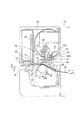
図1は、本発明を適用した実施形態に係るプリンター1(印刷装置)の構成を示す要部側面視図であり、図2は、プラテンローラー11と印刷ヘッド30との配置構成を示す斜視図である。図1にはプリンター1の本体ケース10内部の構成を側面視で示している。図1の左側が、プリンター1の前側に相当する。
プリンター1は、略箱形の本体ケース10の内部に、プラテンローラー11、印刷ヘッド30、オートカッター13、及び手動カッター14等の各種の機能部を備えている。プリンター1は、プラテンローラー11の回転により、記録媒体としての連続紙Mを搬送し、印刷ヘッド30によって、連続紙Mの印刷面に文字や画像を印刷する。印刷された連続紙Mは、本体ケース10の前面に開口する排紙口16から排出される。
Hereinafter, embodiments of the present invention will be described with reference to the drawings.
FIG. 1 is a side view of an essential part showing a configuration of a printer 1 (printing apparatus) according to an embodiment to which the present invention is applied, and FIG. 2 is a perspective view showing an arrangement configuration of a
The printer 1 includes various functional units such as a
連続紙Mは、本体ケース10内の後部に設けられた用紙収容部(図示略)または本体ケース10の外部において後方に設けられた用紙集積部(図示略)に収められている。連続紙Mは、ファンフォールド紙やロール紙等の連続紙であり、紙以外に合成樹脂製のシートであってもよいし、表面加工が施されていてもよい。本実施形態の連続紙Mは、感熱紙であり、印刷ヘッド30により熱せられて発色する。
The continuous paper M is stored in a paper storage portion (not shown) provided at the rear of the
印刷ヘッド30は、本体ケース10の略中央にプラテンローラー11とともに配置されている。印刷ヘッド30は、ヘッド本体部12を金属板等からなるベース21に取り付けて構成され、ベース21は本体ケース10の左右両端に配置された一対のサイドフレーム15(図2)に、後述するように移動可能に支持される。
印刷ヘッド30のヘッド本体部12は、連続紙Mの搬送方向と交差する方向(プラテンローラー11の軸方向)に延在し、該連続紙Mの搬送経路を挟んでプラテンローラー11に対向するように配置されている。また、プラテンローラー11は、本体ケース10の一対のサイドフレーム15(図2)に掛け渡され、回転可能に支持されている。
印刷ヘッド30のベース21と、本体ケース10の上部に位置する上部フレーム31との間にはバネ22(付勢手段)が配置されている。バネ22は圧縮コイルバネであり、一端が上部フレーム31に固定されている。このため、バネ22がベース21をプラテンローラー11に向けて押しており、このバネ22の力によって、印刷ヘッド30のヘッド本体部12は、プラテンローラー11に押圧される。
The
The head
A spring 22 (biasing means) is disposed between the
プラテンローラー11は、本体ケース10内部に配置された搬送モーター32に、図示しない駆動輪列を介して連結されている。プラテンローラー11は、搬送モーター32により駆動されて回転する。
プラテンローラー11は、上記のように印刷ヘッド30のヘッド本体部12と密着しており、このヘッド本体部12とプラテンローラー11との間に連続紙Mが挟まれる。搬送モーター32の動作によりプラテンローラー11が回転すると、連続紙Mは、プラテンローラー11の回転に伴って搬送される。プラテンローラー11の表面は、エラストマー等の、弾性を有し摩擦係数の高い材料で覆われている。プラテンローラー11とヘッド本体部12とがバネ22の力により押圧されていることと合わせて、連続紙Mは、プラテンローラー11によってすべり無く搬送される。
The
As described above, the
搬送モーター32は、制御部(図示略)の制御により、回転方向を正転と逆転とに切り換えて、回転可能である。このため、プラテンローラー11は、図中に矢印FRで示す正方向と、矢印RRで示す逆方向とに回転する。プラテンローラー11が正方向(FR)に回転すると、連続紙Mは図中Fで示す正方向に搬送される。また、プラテンローラー11が逆方向(RR)に回転すると、連続紙Mは図中Rで示す逆方向に搬送される。プラテンローラー11の正方向(FR)、及び、連続紙Mの正方向(F)は、連続紙Mに印刷を行う場合の基準搬送方向である。
The
プラテンローラー11及びヘッド本体部12の後方には、連続紙Mをヘッド本体部12に向けてガイドする一対の紙案内25、26が配置されている。紙案内25は連続紙Mの搬送路の下方に位置し、紙案内26は連続紙Mの搬送路の上方に位置する。連続紙Mは、ヘッド本体部12の後方から、紙案内25、26の間を通ってプラテンローラー11とヘッド本体部12との間に送られ、プラテンローラー11とヘッド本体部12とに挟まれて(ニップされて)搬送される。
ヘッド本体部12には連続紙Mの印刷面が接する。ヘッド本体部12は、連続紙Mの幅方向に並ぶ複数の発熱部12a(印刷部)を有し、これら発熱部12aを適宜発熱させて連続紙Mの印刷面を加熱し、文字や画像等を印刷する。
A pair of paper guides 25 and 26 for guiding the continuous paper M toward the head
The print surface of the continuous paper M is in contact with the head
プラテンローラー11の前方、即ち搬送経路において下流側には、連続紙Mの下方に位置する紙案内27が配置され、さらに前方にはオートカッター13が配置されている。オートカッター13は、連続紙Mの下方に固定された固定刃41と、連続紙Mの上方に位置する可動刃42と、可動刃42を動かすカッター駆動モーター(図示略)とを備える。後述する制御部によって、カッター駆動モーター(図示略)が回転すると、可動刃42が連続紙Mに向けて回動し、連続紙Mを切断する。
A
オートカッター13の前方には、手動カッター14が配置されている。手動カッター14は、排紙口16の内部にあり、連続紙Mの上方から下向きに突出する刃である。手動カッター14は、オートカッター13を使わずに連続紙Mを手動でカットするために設けられる。排紙口16から排出された連続紙Mを、プリンター1を操作するオペレーターが手に持ち、手動カッター14に当たるように持ち上げると、連続紙Mが手動カッター14によりカットされる。
A
次に、印刷ヘッド30の支持構造について説明する。
印刷ヘッド30は、図1に示すように、ヘッド本体部12をプラテンローラー11に押圧して支持する支持機構50を備える。この支持機構50は、ヘッド本体部12を支持するベース21と、このベース21をプラテンローラー11に押しつける方向に付勢するバネ22と、このバネ22の一端が固定される上部フレーム31に固定される支持フレーム33とを備えて構成されている。
ベース21は、図2に示すように、幅方向の両端を折り曲げて形成される側面部34と、連続紙Mの基準搬送方向の上流側(以下、搬送上流側という)に位置する端部を折り曲げた舌片部35とを備える。側面部34は、それぞれ本体ケース10のサイドフレーム15に対向して配置される。また、側面部34は、連続紙Mの搬送上流側に切欠部34Aが形成され、この切欠部34Aには、サイドフレーム15に立設されたピン36(突起)が入り込んでいる。ピン36は切欠部34Aの内縁34Bに当接して、側面部34がそれ以上、連続紙Mの基準搬送方向の下流側(以下、搬送下流側という)に移動しないように規制している。このため、ヘッド本体部12は、バネ22の付勢力でプラテンローラー11に押圧されるとともに、側面部34及びピン36により連続紙Mの搬送下流側(矢印F方向側)への移動が規制され、適切な位置を保っている。なお、ピン36が切欠部34Aの内縁34Bに当接する位置は、印刷ヘッド30の通常の印刷位置である。
Next, a support structure for the
As shown in FIG. 1, the
As shown in FIG. 2, the
切欠部34Aはピン36よりも大きく形成されているため、ピン36が切欠部34A内を動く方向であれば、側面部34を動かすことが可能である。具体的には、側面部34は、連続紙Mの搬送上流側(矢印R方向側)に移動可能である。サイドフレーム15には、ピン36よりも連続紙Mの搬送上流側であって、高さ方向上方に別のピン37(突起)が設けられている。このピン37は、側面部34が連続紙Mの搬送上流側に移動した場合に、側面部34の外縁34Cに当接し、それ以上、連続紙Mの搬送上流側に移動しないように規制している。このため、本実施形態では、印刷ヘッド30(ヘッド本体部12)は、2つのピン36,37で規制された範囲を、連続紙Mの搬送方向に沿って移動可能に構成されている。
Since the
舌片部35は、図3に示すように、略中央部に開口35Aが形成され、この開口35Aのプラテンローラー11から遠い側の縁部には、開口35A内に向けて延びる支点39が設けられている。この支点39は、プラテンローラー11に対向して延びるヘッド本体部12の延在方向(幅方向)の略中央部に設けられている。また、支点39は、例えば、樹脂材料等で形成されて固定金具38に固着され、この固定金具38を開口35Aの縁部に取り付けることにより設けられている。なお、支点39は、固定金具38と別部材の樹脂材料等で形成する場合のみならず、固定金具と同一部材で一体に形成することも可能である。
支持フレーム33は、図1に示すように、上部フレーム31にねじ45により固定されている。この支持フレーム33は、ヘッド本体部12の背面側で、連続紙Mの搬送上流側に折り曲げられた支持片(支持部)40を備え、この支持片40は、上記した舌片部35の開口35A内に延びて支点39と当接する。
本構成では、ヘッド本体部12は、図3に示すように、ベース21を介して、一対のバネ22,22によってプラテンローラー11に押し付けられると共に、これらバネ22,22の間に配置される支点39により、支持フレーム33の支持片40に当接する。このため、ヘッド本体部12は、バネ22,22の伸長に合わせて、支点39を中心として、図3中X方向に揺動することができ、ヘッド本体部12をプラテンローラー11に均一に押し付けることができる。従って、ヘッド本体部12に、例えば、取付位置公差や捻じれ等の部品ばらつきがあった場合であっても、このばらつきを吸収してプラテンローラー11に均一に押圧できるため、印字の擦れや連続紙Mのスキューを防止できる。
また、本構成では、側面部34に形成された切り欠き34Aは、上記した内縁34Bを除いて、ピン36に当接しない程度に大きく形成されている。このため、ヘッド本体部12が揺動する際に、ピン36が該揺動動作を規制することはなく、ヘッド本体部12をプラテンローラー11に均一に押し付けることができる。
As shown in FIG. 3, the
As shown in FIG. 1, the
In this configuration, as shown in FIG. 3, the head
Further, in this configuration, the
また、支持片40は、図1に示すように、先端をプラテンローラー11から離間する方向に傾斜させた傾斜面40Aを備える。このため、側面部34が連続紙Mの搬送上流側に移動した場合には、傾斜面40A上を支点39が案内されることにより、ヘッド本体部12はプラテンローラー11から離間する方向に移動する。
As shown in FIG. 1, the
次に、ヘッド本体部12に貼り付いた連続紙Mを剥がす動作について説明する。
プリンター1は、連続紙Mの印刷面がヘッド本体部12に密着する構成となっているため、連続紙Mを搬送せず停止した状態が続くと、連続紙Mがヘッド本体部12に貼り付いてしまい、連続紙Mがヘッド本体部12の表面で滑らなくなることがある。プリンター1は、この貼り付きを解消するための構造を備えている。
Next, an operation for peeling the continuous paper M attached to the head
Since the printer 1 has a configuration in which the printing surface of the continuous paper M is in close contact with the head
図4には、プラテンローラー11が正方向(FR)に回転する状態を示している。つまり、プラテンローラー11の正方向(FR)への回転中、及び、正方向(FR)への回転が停止した後には、図4に示す状態となる。また、プラテンローラー11が逆方向(RR)に回転すると、ヘッド本体部12、ベース21及び側面部34は一体となって後方に移動し、図5に示す状態に移行する。
FIG. 4 shows a state where the
本構成では、支持フレーム33は、連続紙Mの搬送方向と交差する方向に延びるベース21の延在方向略中央に設けられた支点39と当接する支持片40を備え、この支持片40は、図4及び図5に示すように、先端をプラテンローラー11から離間する方向に傾斜させた傾斜面40Aを備える。
プラテンローラー11が逆方向(RR)(第1の方向)に回転すると、ヘッド本体部12及びベース21が連続紙Mの搬送上流側に移動し、傾斜面40A上を支点39が案内される。このため、ヘッド本体部12は、側面部34とともに後方かつ上方に移動することにより、プラテンローラー11から離れる方向(プラテンローラーと当接する位置を変化させる方向)に移動する。さらに、図4に示した状態ではバネ22の力はプラテンローラー11とヘッド本体部12のニップ部に向いていたのに対し、図5に示す状態では、バネ22が傾いているため、バネ22の力がプラテンローラー11からずれた方向に向いている。このため、ヘッド本体部12が後方に移動することで、プラテンローラー11とヘッド本体部12とを密着させる力は弱くなり、プラテンローラー11による押圧から開放される。
In this configuration, the
When the
図4に示す状態で連続紙Mの印刷面がヘッド本体部12に貼り付いた場合、プラテンローラー11が逆方向(RR)に回転すると、貼り付きが解除される。すなわち、プラテンローラー11の逆回転によって、ヘッド本体部12がプラテンローラー11から離れる方向に移動するので、ヘッド本体部12と連続紙Mが密着している位置では押圧が弱まり、連続紙Mがヘッド本体部12から剥がれやすくなる。これに加えて、連続紙Mは、逆方向(R)の搬送力により、紙案内26によって下向きに案内される。その結果、ヘッド本体部12から離れるように搬送される。このように、プリンター1では、プラテンローラー11を逆方向(RR)に回転させることで、ヘッド本体部12と連続紙Mの貼り付きを容易に解消できる。さらに、プラテンローラー11を逆方向(RR)に回転させた後に正方向(第2の方向)に回転させることを繰り返し行うことで、より確実にヘッド本体部12と連続紙Mとの貼り付きを解消できる。
In the state shown in FIG. 4, when the printing surface of the continuous paper M sticks to the head
以上、説明したように、本実施形態のプリンター1は、連続紙Mを搬送するプラテンローラー11と、連続紙Mを印刷する発熱部12aを有してプラテンローラー11と対峙するヘッド本体部12を備える印刷ヘッド30とを備える。印刷ヘッド30は、ヘッド本体部12をプラテンローラー11に押圧して支持する支持機構50を備える。支持機構50は、連続紙Mの搬送方向と交差する方向に延びるヘッド本体部12の延在方向略中央に設けられた支点39を支持する支持片40を備える。
これにより、ヘッド本体部12は、支点39を中心に揺動自在に支持されるため、ヘッド本体部12をプラテンローラー11に均一に押圧することができ、ヘッド本体部12とプラテンローラー11の押圧の均一化を図り、印字品質の低下もしくは紙送りスキューを防止することができる。また、支持機構50は、プラテンローラー11にヘッド本体部12を押圧した状態で、プラテンローラー11を逆方向に回転させて前記ヘッド本体部12を連続紙Mの搬送上流側に移動可能に支持したため、容易に記録媒体の貼り付きを解消することができる。
As described above, the printer 1 according to this embodiment includes the
As a result, the head
また、本実施形態によれば、支持機構50は、支点39を支持片40の対向面に沿って案内することで、ヘッド本体部12を連続紙Mの搬送方向上流側に移動させるため、ヘッド本体部12を揺動させる動作、及び、プラテンローラー11を移動させる動作の双方を、ヘッド本体部12に設けた支点39と支持片40とで実現することができ、構成の簡素化を図ることができる。
Further, according to the present embodiment, the
また、本実施形態によれば、支持機構50は、プラテンローラー11を逆方向(RR)へ回転することで、ヘッド本体部12を連続紙Mの搬送方向上流側に移動させるため、既存のプラテンローラー11による搬送動作によって貼り付き解消動作を行うことができ、ヘッド本体部12を移動させるための駆動源を新たに設ける必要がない。よって、装置構成を複雑にする必要がなく、低コストで貼り付き解消を実現できる。
Further, according to the present embodiment, the
また、本実施形態によれば、支持片40は、プラテンローラー11から離間する方向に傾斜する傾斜面40Aを備え、この傾斜面40Aに沿って支点39を案内するため、支点39が傾斜面40Aに沿って案内されて押圧位置を移動させるのに伴い、ヘッド本体部12がプラテンローラー11から離間される。これにより、連続紙Mの貼り付き面に対する立ち上がり角度が増大し、連続紙Mをヘッド本体部12から剥ぎ起こす力がより大きく作用するようになり、速やかに連続紙Mの貼り付きを解消できる。
According to the present embodiment, the
なお、上記実施形態は本発明を適用した好ましい一態様を例示したものであり、本発明はこれに限定されない。上記実施形態は、発熱部12aを中心として連続紙Mがヘッド本体部12に貼り付くものであったが、貼り付き位置は発熱部12aが設けられた部位に限定されるものではない。
In addition, the said embodiment illustrated the preferable one aspect | mode which applied this invention, and this invention is not limited to this. In the above embodiment, the continuous paper M sticks to the head
また、上記実施形態では、連続紙Mを搬送するための搬送力によってヘッド本体部12を引っ張って移動させていたが、連続紙Mの搬送手段とは別の駆動源によってヘッド本体部12を移動させてプラテンローラー11との当接位置をずらすように構成してもよい。
In the above embodiment, the head
1…プリンター(印刷装置)、11…プラテンローラー、12…ヘッド本体部、12a…発熱部(印刷部)、15…サイドフレーム、21…ベース、22…バネ、30…印刷ヘッド、33…支持フレーム、34…側面部、35…舌片部、35A…開口、36…ピン(突起)、37…ピン(突起)、39…支点、40…支持片(支持部)、40A…傾斜面、50…支持機構。 DESCRIPTION OF SYMBOLS 1 ... Printer (printing apparatus), 11 ... Platen roller, 12 ... Head main-body part, 12a ... Heat generating part (printing part), 15 ... Side frame, 21 ... Base, 22 ... Spring, 30 ... Print head, 33 ... Support frame , 34 ... side face part, 35 ... tongue piece part, 35A ... opening, 36 ... pin (projection), 37 ... pin (projection), 39 ... fulcrum, 40 ... support piece (support part), 40A ... inclined surface, 50 ... Support mechanism.
Claims (5)
前記支持機構は、前記記録媒体の搬送方向と交差する方向に延在する前記ヘッド本体部の幅方向中央に設けられた支点を支持する支持部を備え、前記支点を中心に前記ヘッド本体部を揺動自在に支持するとともに、前記プラテンローラーと当接する位置を変化させる方向に前記ヘッド本体部を移動可能に支持し、
前記ヘッド本体部は、前記プラテンローラーが第1の方向へ回転、もしくは、前記第1の方向と逆方向の第2の方向へ回転することによって、移動される、
ことを特徴とする印刷ヘッド。 A head main body that is disposed at a position facing a platen roller that conveys the recording medium and that prints on the recording medium; and a support mechanism that supports the head main body by pressing the head main body against the platen roller.
The support mechanism includes a support portion that supports a fulcrum provided at a center in the width direction of the head main body extending in a direction intersecting with the conveyance direction of the recording medium, and the head main body is arranged around the fulcrum. The head main body is supported so as to be swingable, and the head main body is movably supported in a direction to change the position in contact with the platen roller ,
The head main body is moved by rotating the platen roller in a first direction or in a second direction opposite to the first direction.
A print head characterized by that.
前記支持機構は、前記記録媒体の搬送方向と交差する方向に延在する前記ヘッド本体部の幅方向中央に設けられた支点を支持する支持部を備え、前記支点を中心に前記ヘッド本体部を揺動自在に支持するとともに、前記プラテンローラーと当接する位置を変化させる方向に前記ヘッド本体部を移動可能に支持し、The support mechanism includes a support portion that supports a fulcrum provided at a center in the width direction of the head main body extending in a direction intersecting with the conveyance direction of the recording medium, and the head main body is arranged around the fulcrum. The head main body is supported so as to be swingable, and the head main body is movably supported in a direction to change the position in contact with the platen roller,
前記支持部は、前記プラテンローラーから離間する方向に傾斜する傾斜面を有し、前記傾斜面に沿って前記支点を案内するThe support portion has an inclined surface inclined in a direction away from the platen roller, and guides the fulcrum along the inclined surface.
ことを特徴とする印刷ヘッド。A print head characterized by that.
前記支持機構は、前記記録媒体の搬送方向と交差する方向に延在する前記ヘッド本体部の幅方向中央に設けられた支点を支持する支持部を備え、前記支点を中心に前記ヘッド本体部を揺動自在に支持するとともに、前記プラテンローラーと当接する位置を変化させる方向に前記ヘッド本体部を移動可能に支持し、
前記ヘッド本体部は、前記プラテンローラーが第1の方向へ回転、もしくは、前記第1の方向と逆方向の第2の方向へ回転することによって、移動される、
ことを特徴とする印刷装置。 A platen roller that conveys the recording medium, a head main body that is disposed at a position facing the platen roller and prints on the recording medium, and a support mechanism that supports the head main body by pressing the head main body against the platen roller. ,
The support mechanism includes a support portion that supports a fulcrum provided at a center in the width direction of the head main body extending in a direction intersecting with the conveyance direction of the recording medium, and the head main body is arranged around the fulcrum. The head main body is supported so as to be swingable, and the head main body is movably supported in a direction to change the position in contact with the platen roller ,
The head main body is moved by rotating the platen roller in a first direction or in a second direction opposite to the first direction.
A printing apparatus characterized by that.
前記支持機構は、前記記録媒体の搬送方向と交差する方向に延在する前記ヘッド本体部の幅方向中央に設けられた支点を支持する支持部を備え、前記支点を中心に前記ヘッド本体部を揺動自在に支持するとともに、前記プラテンローラーと当接する位置を変化させる方向に前記ヘッド本体部を移動可能に支持し、The support mechanism includes a support portion that supports a fulcrum provided at a center in the width direction of the head main body extending in a direction intersecting with the conveyance direction of the recording medium, and the head main body is arranged around the fulcrum. The head main body is supported so as to be swingable, and the head main body is movably supported in a direction to change the position in contact with the platen roller,
前記支持部は、前記プラテンローラーから離間する方向に傾斜する傾斜面を有し、前記傾斜面に沿って前記支点を案内する、The support portion has an inclined surface inclined in a direction away from the platen roller, and guides the fulcrum along the inclined surface.
ことを特徴とする印刷装置。A printing apparatus characterized by that.
Priority Applications (3)
| Application Number | Priority Date | Filing Date | Title |
|---|---|---|---|
| JP2013180017A JP6225567B2 (en) | 2013-08-30 | 2013-08-30 | Print head and printing apparatus |
| CN201410300885.7A CN104275948B (en) | 2013-07-04 | 2014-06-27 | The alignment method of printing equipment, print head and printing equipment |
| US14/323,139 US9139017B2 (en) | 2013-07-04 | 2014-07-03 | Printing device, printhead, and method of positioning print media in a printer |
Applications Claiming Priority (1)
| Application Number | Priority Date | Filing Date | Title |
|---|---|---|---|
| JP2013180017A JP6225567B2 (en) | 2013-08-30 | 2013-08-30 | Print head and printing apparatus |
Publications (3)
| Publication Number | Publication Date |
|---|---|
| JP2015047741A JP2015047741A (en) | 2015-03-16 |
| JP2015047741A5 JP2015047741A5 (en) | 2016-09-01 |
| JP6225567B2 true JP6225567B2 (en) | 2017-11-08 |
Family
ID=52698178
Family Applications (1)
| Application Number | Title | Priority Date | Filing Date |
|---|---|---|---|
| JP2013180017A Expired - Fee Related JP6225567B2 (en) | 2013-07-04 | 2013-08-30 | Print head and printing apparatus |
Country Status (1)
| Country | Link |
|---|---|
| JP (1) | JP6225567B2 (en) |
Families Citing this family (1)
| Publication number | Priority date | Publication date | Assignee | Title |
|---|---|---|---|---|
| CN217705204U (en) * | 2021-04-22 | 2022-11-01 | 厦门汉印电子技术有限公司 | Flip type printer |
Family Cites Families (7)
| Publication number | Priority date | Publication date | Assignee | Title |
|---|---|---|---|---|
| JP2562709B2 (en) * | 1990-03-27 | 1996-12-11 | 株式会社田村電機製作所 | Print head holding structure |
| JPH04369961A (en) * | 1991-04-08 | 1992-12-22 | Ricoh Co Ltd | Printer and image reader |
| JPH0513750U (en) * | 1991-07-31 | 1993-02-23 | 日本ビクター株式会社 | Thermal transfer printer |
| JPH06320829A (en) * | 1993-05-14 | 1994-11-22 | Tohoku Ricoh Co Ltd | Thermal printer |
| JP2770141B2 (en) * | 1994-11-08 | 1998-06-25 | セイコーインスツルメンツ株式会社 | Printer |
| JP4251014B2 (en) * | 2003-05-22 | 2009-04-08 | セイコーエプソン株式会社 | Printer and printer control method |
| JP5821376B2 (en) * | 2010-08-17 | 2015-11-24 | セイコーエプソン株式会社 | printer |
-
2013
- 2013-08-30 JP JP2013180017A patent/JP6225567B2/en not_active Expired - Fee Related
Also Published As
| Publication number | Publication date |
|---|---|
| JP2015047741A (en) | 2015-03-16 |
Similar Documents
| Publication | Publication Date | Title |
|---|---|---|
| JP5106238B2 (en) | Printer with cutter | |
| JP5769466B2 (en) | Adhesive label issuing device and printer | |
| JP2011207074A5 (en) | ||
| JP2012210800A (en) | Printer | |
| US10016989B1 (en) | Printing apparatus | |
| JP2017056583A (en) | Label printer | |
| JP6862691B2 (en) | Inkjet printer and peeling device | |
| JP5801222B2 (en) | Cutter device and printer | |
| US11440334B2 (en) | Cutter apparatus and printing apparatus | |
| JP2007045577A (en) | Paper feed mechanism | |
| JP5671820B2 (en) | Recording device | |
| JP6225567B2 (en) | Print head and printing apparatus | |
| JP2007168350A (en) | Thermal printer | |
| JP4910544B2 (en) | Label issuing device | |
| JP5855177B2 (en) | Multiple thermal printer | |
| JPH08192388A (en) | Cutter device | |
| JPH09263348A (en) | Rolled paper feeding device | |
| JP5613703B2 (en) | Label peeling device | |
| JP6966243B2 (en) | Printer | |
| JP4343036B2 (en) | Printer | |
| KR102604532B1 (en) | Device for detecting and removing print paper jams in printer | |
| JP2009179009A (en) | Thermal printer | |
| JP2001063106A (en) | Printer | |
| JP2010253905A (en) | Thermal printer | |
| JP2008007235A (en) | Paper warping correction device and printer |
Legal Events
| Date | Code | Title | Description |
|---|---|---|---|
| A521 | Request for written amendment filed |
Free format text: JAPANESE INTERMEDIATE CODE: A523 Effective date: 20160714 |
|
| A621 | Written request for application examination |
Free format text: JAPANESE INTERMEDIATE CODE: A621 Effective date: 20160714 |
|
| A977 | Report on retrieval |
Free format text: JAPANESE INTERMEDIATE CODE: A971007 Effective date: 20170428 |
|
| A131 | Notification of reasons for refusal |
Free format text: JAPANESE INTERMEDIATE CODE: A131 Effective date: 20170509 |
|
| A521 | Request for written amendment filed |
Free format text: JAPANESE INTERMEDIATE CODE: A523 Effective date: 20170706 |
|
| TRDD | Decision of grant or rejection written | ||
| A01 | Written decision to grant a patent or to grant a registration (utility model) |
Free format text: JAPANESE INTERMEDIATE CODE: A01 Effective date: 20170912 |
|
| A61 | First payment of annual fees (during grant procedure) |
Free format text: JAPANESE INTERMEDIATE CODE: A61 Effective date: 20170925 |
|
| R150 | Certificate of patent or registration of utility model |
Ref document number: 6225567 Country of ref document: JP Free format text: JAPANESE INTERMEDIATE CODE: R150 |
|
| LAPS | Cancellation because of no payment of annual fees |