【0001】
【発明の属する技術分野】
本発明は、長尺の被印刷媒体が巻回されたシートロールから被印刷媒体を引き出して印刷する印刷装置に関し、特に、被印刷媒体をシートロールに巻き戻すことができる印刷装置に関する。
【0002】
【従来の技術】
従来より、上記印刷装置として、長尺の被印刷媒体が巻回されたシートロールを支持するロール支持手段と、該支持されたシートロールから被印刷媒体を引き出して送り方向に搬送するかまたは被印刷媒体を戻し方向に搬送してシートロールに巻き戻す搬送手段と、搬送手段による被印刷媒体の搬送経路上に設けられて被印刷媒体に印刷する印刷手段とを備えているものが知られている(例えば、特許文献1参照。)。この印刷装置では、シートロールから被印刷媒体を引き出して送り方向に搬送する場合、幅方向両端が揃えられて巻回されたシートロールから被印刷媒体が引き出されるため、搬送経路上の印刷手段の箇所で被印刷媒体が幅方向に移動することがなく、被印刷媒体の正確な位置に印刷することができる。
【0003】
【特許文献1】
特開平10−44481号公報
【0004】
【発明が解決しようとする課題】
しかし、この従来の印刷装置では、被印刷媒体が搬送経路の印刷手段よりも下流側で幅方向に自由に移動するため、被印刷媒体を戻し方向に搬送してシートロールに巻き戻す場合に、シートロールに対して被印刷媒体を幅方向両端が揃えられた正常な状態で巻き戻すことができないといった問題がある。この問題は、被印刷媒体を印刷後に装置外に排出するタイプの印刷装置の場合に、排出された被印刷媒体のこじれ等によって顕著なものとなる。
【0005】
そこで本発明は、上記の問題点に鑑み、被印刷媒体を戻し方向に搬送してシートロールに巻き戻す場合に、シートロールに対して被印刷媒体を幅方向両端が揃えられた正常な状態で巻き戻すことができる印刷装置を提供することを課題とする。
【0006】
【課題を解決するための手段】
上記課題を解決するために本発明は、長尺の被印刷媒体が巻回されたシートロールを支持するロール支持手段と、該支持されたシートロールから被印刷媒体を引き出して送り方向に搬送するかまたは被印刷媒体を戻し方向に搬送してシートロールに巻き戻す搬送手段と、搬送手段による被印刷媒体の搬送経路上に設けられて被印刷媒体に印刷する印刷手段と、印刷手段よりも搬送経路下流側に設けられて被印刷媒体の幅方向への移動を規制する規制ガイド部材とを備えていることを特徴とする。
【0007】
これによれば、規制ガイド部材によって、被印刷媒体の印刷手段よりも搬送経路下流側での幅方向の移動が規制される。そのため、被印刷媒体が搬送経路上の正常な位置で搬送され、シートロールに幅方向両端が揃えられた正常な状態で巻き戻すことができる。
【0008】
なお、上記規制ガイド部材は、搬送手段による搬送経路の下流端付近に設けるのが好ましい。
【0009】
また、上記規制ガイド部材は、被印刷媒体の搬送経路に沿って、被印刷媒体を嵌入するガイド溝を備え、該ガイド溝は、被印刷媒体の幅にクリアランスを加えた幅に形成され、被印刷媒体の幅方向端部がガイド溝の溝壁に当接して被印刷媒体の幅方向への移動が規制されるようにしても良い。この場合、上記ガイド溝は、互いに異なる溝幅のものが複数備えられ、該複数のガイド溝は、溝中心を同一として、溝幅が狭いガイド溝ほど深く形成されるようにするのが好ましい。
【0010】
また、上記規制ガイド部材は、被印刷媒体が長尺状台紙にラベルを貼着した台紙付きラベルの場合に、台紙付きラベルに対して台紙側から当接して長尺状台紙を折曲することによりラベルを長尺状台紙から剥離する折曲部材を構成するようにしても良い。また、上記規制ガイド部材は、そのガイド幅を被印刷媒体の幅に応じて変更可能に構成しても良い。
【0011】
【発明の実施の形態】
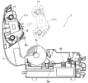
図1及び図2を参照して、1は本発明に係るサーマルプリンタである。このサーマルプリンタ1は、ホストコンピュータ等から送信される印刷データに基づいて印刷処理を行うもので、被印刷媒体Mを搬送し、この搬送経路上に設置されたサーマルヘッド(印刷手段)2を発熱させて印刷を行う。このサーマルヘッド2は、サーマルプリンタ1に備えられた開閉自在のカバー11に取り付けられている。
【0012】
このサーマルプリンタ1では、被印刷媒体Mとして、図3(a)に示すような、同一形状のラベル31が長尺状台紙32の長手方向に同じ向き且つ等ピッチで複数枚貼着された台紙付きラベル、いわゆるダイカットラベル3か、図3(b)に示すような、シート41裏面に粘着層42が被着され、その粘着層42が剥離テープ43で覆われた長尺シート4のどちらかを選択して印刷を行う。本実施形態では、ダイカットラベル3の幅αと長尺シート4の幅βは異なっており、長尺シート4の幅βの方がダイカットラベル3の幅αより幅広となっている。これら被印刷媒体Mは、芯材Pに巻回されたシートロールRの状態でサーマルプリンタ1のシートロール収容部12にセットされる。シートロールRの芯材Pの両側には、円形のフランジ51を有する軸部材5がそれぞれ差し込まれており、この軸部材5のフランジ51によって被印刷媒体Mの幅方向への移動が規制される。フランジ51の直径は、シートロールRの最大外径よりも大径となるように設定されている。
【0013】
サーマルプリンタ1は、シートロールRから引き出された被印刷媒体Mを搬送する搬送手段として、搬送ローラ6a、6bと、プラテンローラ6cとを備える。搬送ローラ6aは、サーマルヘッド2よりも搬送経路の上流側(シートロール収容部12側)に設けられており、カバー11を閉じたときにカバー11側に設けられた狭持ローラ(狭持部材)6dと対向して被印刷媒体Mを挟むように設けられている。また、搬送ローラ6bは、サーマルヘッド2よりも搬送経路の下流側に設けられており、カバー11を閉じたときにカバー11側に設けられた狭持ローラ(狭持部材)6eと対向して被印刷媒体Mを挟むように設けられている。また、プラテンローラ6cは、カバー11を閉じたときにサーマルヘッド(狭持部材)2と対向して被印刷媒体Mを挟むように設けられている。
【0014】
これら搬送ローラ6a、6bとプラテンローラ6cは、図4に示すように、正逆回転可能なステッピングモータ7を駆動源としている。このステッピングモータ7のモータ軸7aの回転力は、中間ギア7b、7cを介して、搬送ローラ6aが接続される被動ギア7dとプラテンローラ6cが接続される被動ギア7eとに伝達される。そして、被動ギア7dに伝達された回転力は、さらに、中間ギア7fを介して、後述するロール回転軸8がワンウェイクラッチ(図示しない)を介して連結される被動ギア7gに伝達され、被動ギア7eに伝達された回転力は、さらに、中間ギア7hを介して、搬送ローラ6bが接続される被動ギア7iに接続される。そして、被動ギア7iに伝達された回転力は、さらに、中間ギア7j、7kを介して、後述するローラ15bに接続される被動ギア7lに接続される。
【0015】
このようなギア配列(7a〜7l)のステッピングモータ7駆動系により、ステッピングモータ7のモータ軸7aが一方向(矢印a方向)に回転すると、被動ギア7d、7e、7iは一方向(矢印c方向)に回転する。被動ギア7d、7e、7iが矢印c方向に回転すると、これら被動ギア7d、7e、7iに接続された搬送ローラ6a、6b及びプラテンローラ6cもそれぞれ矢印c方向に回転し、被印刷媒体Mを戻し方向(搬送経路上流方向)に搬送する。
【0016】
また、モータ軸7aが他方向(矢印b方向)に回転すると、被動ギア7d、7e、7iは他方向(矢印d方向)に回転する。被動ギア7d、7e、7iが矢印d方向に回転すると、これら被動ギア7d、7e、7iに接続された搬送ローラ6a、6b及びプラテンローラ6cもそれぞれ矢印d方向に回転し、被印刷媒体Mを送り方向(搬送経路下流方向)に搬送する。なお、サーマルヘッド2を発熱させて印刷を行う場合には、被印刷媒体Mは送り方向に搬送される。
【0017】
被動ギア7dと被動ギア7eとは外径が同径に形成されている共にこれら被動ギア7d、7eの外径と被動ギア7iの外径とは1.34:1の比で形成されている。一方、被動ギア7d、7eに接続されている搬送ローラ6a及びプラテンローラ6cの外径と、被動ギア7iに接続されている搬送ローラ6bの外径との比も1.34:1となるように形成されている。したがって、搬送ローラ6a、6b及びプラテンローラ6cのそれぞれによる被印刷媒体Mの搬送量は互いに等しくなっている。
【0018】
上記狭持ローラ6d、6eは、図示しない圧接解除機構によって、ローラ軸方向片側が上下方向に移動可能になっている。狭持ローラ6d、6eのローラ軸方向片側を下方に移動させると、搬送ローラ6a、6bとの間に被印刷媒体Mをそれぞれ狭持し、狭持ローラ6d、6eのローラ軸方向片側を上方に移動させると、搬送ローラ6a、6bとの間の被印刷媒体Mの狭持が解除される(狭持解除手段)。
【0019】
上記サーマルヘッド2は、上述したように、カバー11に取り付けられており、カバー11を閉じた時にプラテンローラ6cの上方に位置するように設けられている。このサーマルヘッド2は、カム機構10a及び加圧バネ10bの作用によって上下方向に移動可能になっている。加圧バネ10bの付勢力によってサーマルヘッド2を下方に移動させると、プラテンローラ6bとの間に被印刷媒体Mを狭持し、カム機構10aによってサーマルヘッド2を上方に移動させると、プラテンローラ6cとの間の被印刷媒体Mの狭持が解除される(狭持解除手段)。
【0020】
シートロール収容部12の前部には、円筒状のゴムが装着されたロール回転軸8が設けられている。このロール回転軸8は、上述したように、ワンウェイクラッチを介してステッピングモータ7の駆動系の被動ギア7gと連結されている。
これにより、ステッピングモータ7のモータ軸7aが矢印a方向に回転すると、この回転力がギア7b、7c、7d、7f、7g及びワンウェイクラッチを介して伝達され、ロール回転軸8が一方向(矢印c方向)に回転する。
【0021】
また、ステッピングモータ7のモータ軸7aが矢印b方向に回転すると、この回転力はギア7b、7c、7d、7fを介して被動ギア7gまでは伝達されるが、ワンウェイクラッチによって遮断され、ロール回転軸8は回転しない。なお、このとき、ロール回転軸8は、被動ギア7gの回転量を最大回転量として、ステッピングモータ7の駆動系から以外の外力によって矢印d方向に回転可能となっている。
【0022】
シートロール収容部12の後部には、回転自在の支持ローラ9(補助支持部材)が設けられており、上記シートロールRは、フランジ51が支持ローラ9及びロール回転軸8に当接した状態で、それら支持ローラ9及びロール回転軸8の上に載架されて支持される。この支持状態で、モータ7の回転力によってロール回転軸8が矢印c方向に回転すると、これと当接するフランジ51が一方向(図1、矢印e方向)に回転し、被印刷媒体MがシートロールRに巻き戻される。
【0023】
ここで、ロール回転軸8がワンウェイクラッチを介して接続されている被動ギア7gの外径と、搬送ローラ6aが接続されている被動ギア7dの外径とは、1:1.34の比で形成されている。一方、ロール回転軸8自体の外径は、搬送ローラ6aの外径と同径に形成されている。これにより、回転軸8による被印刷媒体Mの巻き戻し量は、搬送ローラ6aによる被印刷媒体Mの搬送量よりも常に大きくなるように設定されている。すなわち、シートロールRの外径が最小の場合にはロール回転軸8による被印刷媒体Mの巻き戻し量が最小となるが、その場合でも、ステッピングモータ7単位回転数あたりのロール回転軸8の回転による被印刷媒体Mの巻き戻し量が、搬送ローラ6a、6b及びプラテンローラ6cによる被印刷媒体Mの搬送量よりも大きくなるように設定されている。
【0024】
また、図5に示すように、カバー11にはインクリボンカセット11が着脱自在に取り付けられ、インクリボンカセット11をカバー11に装着すると、インクリボンカセッ11のインクリボン111がサーマルヘッド2を覆うように構成されている。印刷時には、サーマルヘッド2が下方に移動し、インクリボン111を被印刷媒体Mに圧接した状態で、被印刷媒体Mを搬送ローラと6bの間に狭持する。この圧接状態で、搬送ローラ6a、6bを回転させて被印刷媒体Mを送り方向に搬送しながらサーマルヘッド2を発熱させることにより、インクリボン111のインクを溶融して被印刷媒体Mに所定の印刷データを印刷する。
【0025】
サーマルプリンタ1は、サーマルヘッド2よりも搬送経路の下流側に、被印刷媒体Mを幅方向に切断する円盤状のカッタ12を備えている。カッタ12は円盤の全周に切刃が形成され、カッタ12が回転しながら左右に移動して被印刷媒体を切断する。
【0026】
カッタ12よりも搬送経路の下流側には、被印刷媒体Mとしてダイカットラベル3を選択し、後述するラベルピールモードで印刷を行う場合に、そのダイカットラベル3に対して長尺状台紙32側から当接して長尺状台紙32を下方に折曲げる板状の折曲部材(規制ガイド部材)13が設けられている。この折曲部材13の上部には、図6(a)、(b)に示すように、深さ及び幅の異なる2段のガイド溝131、132が設けられている。ガイド溝131の幅はダイカットラベル3の幅αよりも1、2mm程度大きく設けられており、被印刷媒体Mとしてダイカットラベル3を選択した場合にはこの溝131にダイカットラベル3が収められる。ガイド溝132の幅は長尺シート4の幅βよりも1、2mm程度大きく設けられており、被印刷媒体Mとして長尺シート4を選択した場合にはこの溝132に長尺シート4が収められる。そして、ダイカットラベル3及び長尺シート4は、幅方向端部がこれらガイド溝131、132の溝壁に当接することにより、幅方向への移動が規制される。
【0027】
サーマルプリンタ1の前面には、カバー11を開いた状態で前方に引き開くことのできるフロントパネル14が取り付けられている。このフロントパネル14には上下2段に排出口141、142が開口している。
【0028】
フロントパネル14内には、被印刷媒体Mとしてダイカットラベル3を選択し、後述するラベルピールモードで印刷を行う場合に、折曲部材13によって下方に折曲げられた長尺状台紙32を挟んで引っ張り、下部排出口142から外部へと送り出す1対のローラ15a、15bが備えられている。ローラ15aはサーマルプリンタ1の本体側に取り付けられ自由に回転し、ローラ15bはフロントパネル14に取り付けられると共に、上述したようにステッピングモータ7駆動系の被動ギア7lに接続され、搬送ローラ6a、6b及びプラテンローラ6cと同期して回転する。
【0029】
このサーマルプリンタ1でダイカットラベル3に印刷する場合、ラベルピールモード、すなわち印刷されたラベル31を長尺状台紙32から剥離させて上部排出口141から排出すると共に長尺状台紙32を下部排出口142から排出するモードでの印刷処理と、非ラベルピールモード、すなわち印刷されたラベル31を長尺状台紙32から剥離させず長尺状台紙32に貼着されたままの状態で上部排出口141から排出するモードでの印刷処理とを選択することができる。
【0030】
ラベルピールモードでの印刷処理を選択した場合には、図7に示すように、長尺状台紙32は上部排出口141の直前で折曲部材13のガイド溝131の溝底部分で下方に折曲げられ、上記ローラ15a、15bに挟まれて下方に引っ張られる。ラベル31は、長尺状台紙32からラベル31の後端の一部、例えば5mm程度を残して剥離し、上部排出口141を通って前方へ排出される。
【0031】
非ラベルピールモードでの印刷処理を選択した場合には、さらに、印刷された各ラベル31間で長尺状台紙32を切断してラベル31を1枚毎に排出する単独ラベル形成モードか、一番最後に印刷されたラベル31の上流側の長尺状台紙32のみをカッタ12で切断し、ラベル31間の長尺状台紙32を連続した状態で排出する連続ラベル形成モードかを選択して印刷を行う。
【0032】
また、このサーマルプリンタ1で長尺シート4に印刷する場合、単色印刷モードでの印刷処理と、複数色印刷モードでの印刷処理とを選択することができる。
複数色印刷モードでの印刷処理では、複数色のインクリボン111での印刷が必要となるため、1色の印刷の終了後、長尺シート4を巻き戻し、インクリボンカセット11を交換して、次の色の印刷を行う。そして全ての色についてこれらの工程を繰り返し、印刷処理が完了する。
【0033】
カバー11にはインクリボン111の有無およびインクリボン111の色種を検知するインクリボンセンサ16aが設けられている。また、サーマルヘッド2の下流側には、被印刷媒体Mの先端を検出する反射式の先端検知センサ16bが設けられている。また、搬送ローラ6aの上流側であってロール回転軸8の下流側には、被印刷媒体Mの有無を検知する接触式の媒体センサ16cが設けられている。また、16dはピールセンサであり、被印刷媒体Mとしてダイカットラベル3を選択し、ラベルピールモードで印刷を行う場合に、長尺状台紙32から剥離して上部の排出口141を通って前方に排出された状態のラベル31を検知するものである。また、16eは反射式の台紙センサであり、被印刷媒体Mとしてダイカットラベル3を選択し、ラベルピールモードで印刷を行う場合に、ローラ15a、15bに挟まれた状態にセットされ、下部の排出口142を通って前方に排出された状態の長尺状台紙32を検知するものである。
【0034】
次に、被印刷媒体Mを送り方向に搬送する場合、例えば、ダイカットラベル3または長尺シート4の頭出しや印刷、ダイカットラベル3のラベルピールモードでの剥離処理等のために搬送を行う場合の、サーマルプリンタ1の動作を説明する。
【0035】
被印刷媒体Mを送り方向に搬送する場合、サーマルプリンタ1に備えられたCPU(図示しない)が上記狭持解除手段を制御して、狭持ローラ6d、6e及びサーマルヘッド2を下方に位置させ、それぞれ搬送ローラ6a、6b及びプラテンローラ6cとの間に被印刷媒体Mを狭持した状態にする。そして、CPUがステッピングモータ7を制御してモータ軸7aを矢印b方向に回転させる。このステッピングモータ7の回転力は駆動系を介して搬送ローラ6a、6b及びプラテンローラ6cに伝達され、搬送ローラ6a、6b及びプラテンローラ6cが矢印d方向に回転する。このとき、シートロールRと当接しているロール回転軸8は、ワンウェイクラッチの作用によってステッピングモータ7の回転力の伝達が遮断されており、被動ギア7gの回転量を最大回転量として、外力によって矢印d方向に回転可能となっている。
【0036】
これにより、搬送ローラ6a、6b及びプラテンローラ6cの回転によってシートロールRから被印刷媒体Mが引き出されて送り方向に搬送される。このとき、シートロールRは、被動ギア7gの回転量を最大回転量として矢印d方向に回転可能なロール回転軸8及び回転自在の支持ローラ9と連れ回りする。この送り方向の搬送は搬送ローラ6a、6b及びプラテンローラ6cの主導で行われるので、搬送ローラ6a、6b及びプラテンローラ6cの回転量を制御することにより、送り方向に搬送される被印刷媒体Mの量を正確に制御することができる。したがって、上記先端検知センサ16bや媒体センサ16c、ピールセンサ16dによる所定箇所の検知状態から搬送量を制御して被印刷媒体Mを送り方向に搬送することにより、被印刷媒体Mの印刷位置への頭出しのための搬送、サーマルヘッド2での印刷中の搬送、ダイカットラベル3のラベルピールモードでの剥離処理のための搬送等を正確に行うことができる。
【0037】
次に、被印刷媒体Mを戻し方向に搬送する場合、例えば、ダイカットラベル3または長尺シート4の頭出し、長尺シート4の複数色印刷処理のための巻き戻し及び、印刷処理完了後の完全巻き戻し等のために搬送を行う場合の、サーマルプリンタ1の動作を説明する。
【0038】
被印刷媒体Mを戻し方向に搬送する場合であって、搬送量を制御した搬送を行う場合には、CPUが上記狭持解除手段を制御して、狭持ローラ6d、6e及びサーマルヘッド2を下方に位置させ、それぞれ搬送ローラ6a、6b及びプラテンローラ6cとの間に被印刷媒体Mを狭持した状態にする。そして、CPUがステッピングモータ7を制御してモータ軸7aを矢印a方向に回転させる。このステッピングモータ7の回転力は駆動系を介して搬送ローラ6a、6b、プラテンローラ6c及びロール回転軸8に伝達され、搬送ローラ6a、6b、プラテンローラ6c及びロール回転軸8がそれぞれ矢印c方向に回転する。
【0039】
このとき、被印刷媒体Mが狭持ローラ6d、6e及びサーマルヘッド2で狭持されており、かつ、上述したように、ステッピングモータ7単位回転数あたりのロール回転軸8の回転による被印刷媒体Mの巻き戻し量が、搬送ローラ6a、6b及びプラテンローラ6cによる被印刷媒体Mの搬送量よりも大きい。そのため、シートロールRは、ロール回転軸8による巻き戻し量と搬送ローラ6bによる搬送量との差分だけロール回転軸8上を空回りし、搬送ローラ6b−ロール回転軸8間の被印刷媒体Mには適度な張力が与えられる。そして、被印刷媒体Mは戻し方向に搬送されると共に、シートロールRに巻き戻される。この戻し方向の搬送は搬送ローラ6a、6b及びプラテンローラ6cの主導で行われるので、搬送ローラ6a、6b及びプラテンローラ6cの回転量を制御することにより、戻し方向に搬送される被印刷媒体Mの量を正確に制御することができる。したがって、上記先端検知センサ16bや媒体センサ16c、ピールセンサ16dによる所定箇所の検知状態から搬送量を制御して被印刷媒体Mを戻し方向に搬送することにより、被印刷媒体Mの印刷位置への頭出しのための搬送等を正確に行うことができる。
【0040】
被印刷媒体Mを戻し方向に搬送する場合であって、搬送量を制御しない搬送を行う場合には、CPUが上記狭持解除手段を制御して、狭持ローラ6d、6e及びサーマルヘッド2を上方に位置させ、搬送ローラ6a、6b及びプラテンローラ6cとの間の被印刷媒体Mの狭持を解除する。そして、CPUがステッピングモータ7を制御してモータ軸7aを矢印a方向に回転させる。このステッピングモータ7の回転力は駆動系を介して搬送ローラ6a、6b、プラテンローラ6c及びロール回転軸8に伝達され、搬送ローラ6a、6b、プラテンローラ6c及びロール回転軸8がそれぞれ矢印c方向に回転する。
【0041】
このとき、被印刷媒体Mの狭持が解除されており、かつ、上述したように、ステッピングモータ7単位回転数あたりのロール回転軸8の回転による被印刷媒体Mの巻き戻し量が、ステッピングモータ7単位回転数あたりの搬送ローラ6a、6b及びプラテンローラ6cによる被印刷媒体Mの搬送量よりも大きいので、被印刷媒体Mはロール回転軸8の回転によってシートロールRに巻き戻されると共に、搬送ローラ6a、6b上を滑って戻し方向に搬送される。
【0042】
この戻し方向の搬送は、上記先端検知センサ16bや媒体センサ16c、ピールセンサ16dによって所定箇所を検知する場合や、被印刷媒体MをシートロールRに完全に巻き戻す場合に行われる。
【0043】
なお、上記実施形態では、ロール回転軸8に円筒状のゴムを装着することにより、ロール回転軸8とフランジ51との間の摩擦力を確保しているが、これは、フランジ51の方をゴム製にしたり、フランジ51にリング状のゴムを装着したりすることによって摩擦力を確保しても良い。
【0044】
また、上記実施形態では支持ローラ9を回転自在に構成したが、これに代えて次のように構成しても良い。すなわち、支持ローラ9をステッピングモータ7の駆動系に対してワンウェイクラッチを介して連結し、ステッピングモータ7のモータ軸7aが矢印b方向に回転したときにその回転力が伝達されて矢印f方向(図1参照)に回転する。また、シートロールRの外径が最大の場合でも、ステッピングモータ7単位回転数あたりの支持ローラ9の回転による被印刷媒体Mの送り出し量が搬送ローラ6a、6b及びプラテンローラ6cによる被印刷媒体Mの搬送量よりも小さくなるように設定する。このように構成することにより、被印刷媒体Mを送り方向に搬送する場合に、搬送ローラ6a−支持ローラ9間の被印刷媒体Mに適度な張力が与えられ、被印刷媒体Mを適切に搬送することができる。
【0045】
これら搬送量を制御しての戻し方向の搬送、搬送量を制御しない戻し方向の搬送では、被印刷媒体Mを戻し方向に搬送するのと同時に、シートロールRへの巻き戻しも行われている。このとき、折曲部材13のガイド溝131、132によって、被印刷媒体Mの幅方向への移動が規制されるので、サーマルプリンタ1外に排出されている被印刷媒体Mがこじれたり左右に変位したりしていても、折曲部材13よりも搬送経路上流側では正常な位置で搬送される。そのため、シートロールRに幅方向両端が揃えられた正常な状態で被印刷媒体Mを巻き戻すことができる。
【0046】
なお、上記実施形態では、折曲部材13の一方のガイド溝131の溝底のみを、ダイカットラベル3の長尺状台紙32を折り曲げるのに用いたが、本発明はこれに限定されるものではなく、例えば、ガイド溝131の溝幅が狭い場合には、もう一方のガイド溝132も幅広のダイカットラベル3の長尺状台紙32を折り曲げるのに用いることができる。
【0047】
なお、上記実施形態では、被印刷媒体Mの幅方向への移動を規制するガイド溝131、132を折曲部材13の上部に設けたが、本発明はこれに限定されるものではなく、例えば、折曲部材13とは別個に、被印刷媒体Mの幅方向への移動を規制するガイド溝を有する規制ガイド部材を設けるようにしてもよい。
【0048】
また、上記実施形態では、ガイド溝131、132を折曲部材13に設ける関係上、折曲部材13は上部排出口141の直前、すなわち、上部排出口141から被印刷媒体Mを排出する場合の搬送経路下流端付近に設けられているが、本発明はこれに限定されるものではない。上記規制ガイド部材を設ける場合には、サーマルヘッド2よりも搬送経路下流側の適当な位置を選択することができ、例えば、下部排出口142の直前、すなわち、下部排出口142からダイカットラベル3の長尺状台紙32を排出する場合の長尺状台紙32の搬送経路下流端付近に設けても良い。
【0049】
また、被印刷媒体Mの幅方向への移動を規制するガイド溝を有する規制ガイド部材は、ガイド溝の数、各ガイド溝の深さ及び幅を適宜変更することができる。
【0050】
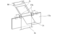
また、規制ガイド部材は、図8に示すように、レール17aと、そのレール17aに摺動自在に支持されて左右対称に変位する一対の押さえ部材17bとで構成することにより、そのガイド幅を被印刷媒体Mの幅に応じて連続的に変更できるようにしても良い。
【0051】
なお、本発明は上記実施形態に限定されるものではなく、必要に応じて種々変更することが可能である。
【0052】
【発明の効果】
以上の説明から明らかなように、本発明は、規制ガイド部材によって、被印刷媒体の印刷手段よりも搬送経路下流側での幅方向の移動が規制される。そのため、被印刷媒体が搬送経路上の正常な位置で搬送され、シートロールに幅方向両端が揃えられた正常な状態で巻き戻すことができる。
【図面の簡単な説明】
【図1】本発明の一実施の形態のサーマルプリンタの側断面図
【図2】カバーを開いて被印刷媒体を取り外した状態のサーマルプリンタの正面図
【図3】被印刷媒体の斜視図
【図4】サーマルプリンタの駆動系を示す図
【図5】カバーを開いた状態のサーマルプリンタの側断面図
【図6】折曲部材を示す斜視図
【図7】ラベルの剥離処理を説明する図
【図8】ガイド幅が可変の規制ガイド部材の斜視図
【符号の説明】
51 フランジ
6a、6b 搬送ローラ
7 駆動モータ
8 ローラ回転軸
13 折曲部材[0001]
TECHNICAL FIELD OF THE INVENTION
The present invention relates to a printing apparatus that pulls out a printing medium from a sheet roll around which a long printing medium is wound and prints the printing medium, and particularly relates to a printing apparatus that can rewind the printing medium to the sheet roll.
[0002]
[Prior art]
Conventionally, as the printing apparatus, a roll supporting means for supporting a sheet roll around which a long printing medium is wound, and a printing medium to be pulled out from the supported sheet roll and conveyed in a feeding direction or to be transferred. There is known a transport device that transports a print medium in a return direction and rewinds the roll to a sheet roll, and a print device that is provided on a transport path of the print medium by the transport device and prints on the print medium. (For example, see Patent Document 1). In this printing apparatus, when the print medium is pulled out from the sheet roll and transported in the feed direction, the print medium is pulled out from the rolled sheet roll having both ends aligned in the width direction. The printing medium can be printed at an accurate position on the printing medium without moving in the width direction at the location.
[0003]
[Patent Document 1]
JP 10-44481 A
[Problems to be solved by the invention]
However, in this conventional printing apparatus, since the print medium moves freely in the width direction on the downstream side of the printing means on the transport path, when the print medium is transported in the return direction and rewound on the sheet roll, There is a problem that the printing medium cannot be rewound with respect to the sheet roll in a normal state in which both ends in the width direction are aligned. This problem is remarkable in a printing apparatus of a type that discharges a print medium after printing to the outside of the apparatus after printing, because the discharged print medium is twisted.
[0005]
Accordingly, the present invention has been made in view of the above problems, and in a case where the print medium is conveyed in the return direction and rewound to the sheet roll, the print medium is aligned with the sheet roll in a normal state in which both ends in the width direction are aligned. It is an object to provide a printing device that can be rewound.
[0006]
[Means for Solving the Problems]
In order to solve the above-described problems, the present invention provides a roll supporting unit that supports a sheet roll around which a long print medium is wound, and pulls out the print medium from the supported sheet roll and conveys the print medium in a feed direction. Or a transporting means for transporting the print medium in the return direction and rewinding it to a sheet roll; a printing means provided on a transport path of the print medium by the transport means for printing on the print medium; A regulating guide member provided on the downstream side of the path to regulate movement of the print medium in the width direction.
[0007]
According to this, the regulation guide member regulates the movement of the print medium in the width direction downstream of the printing unit in the transport path. Therefore, the print medium can be transported at a normal position on the transport path, and can be rewound in a normal state in which both ends in the width direction are aligned with the sheet roll.
[0008]
Preferably, the regulation guide member is provided near the downstream end of the transport path by the transport unit.
[0009]
Further, the regulating guide member includes a guide groove for fitting the print medium along the transport path of the print medium, and the guide groove is formed to have a width obtained by adding a clearance to the width of the print medium, and The end in the width direction of the print medium may be in contact with the groove wall of the guide groove to restrict the movement of the print medium in the width direction. In this case, it is preferable that a plurality of guide grooves having different groove widths are provided, and that the plurality of guide grooves have the same groove center and are formed deeper as the groove width is smaller.
[0010]
In the case where the medium to be printed is a label with a mount on which a label is attached to a long mount, the regulation guide member may abut the label with the mount from the mount side and bend the long mount. May be used to form a bent member that separates the label from the long mount. Further, the regulation guide member may be configured such that its guide width can be changed according to the width of the printing medium.
[0011]
BEST MODE FOR CARRYING OUT THE INVENTION
Referring to FIGS. 1 and 2, reference numeral 1 denotes a thermal printer according to the present invention. The thermal printer 1 performs a printing process based on print data transmitted from a host computer or the like. The thermal printer 1 conveys a print medium M, and heats a thermal head (printing unit) 2 installed on the conveyance path. And print. The thermal head 2 is attached to the cover 1 1 openably provided in the thermal printer 1.
[0012]
In the thermal printer 1, as a print medium M, as shown in FIG. 3 (a), the label 3 1 of the same shape is a plurality stuck at an equal pitch the same direction and in the longitudinal direction of the elongated backing sheet 3 2 mount with labels, so-called die cut label 3 or, as shown in FIG. 3 (b), sheet 4 first adhesive layer 4 2 on the back surface is deposited, the length thereof the adhesive layer 4 2 is covered with a release tape 4 3 One of the length sheets 4 is selected for printing. In the present embodiment, the width α of the die-cut label 3 is different from the width β of the long sheet 4, and the width β of the long sheet 4 is wider than the width α of the die-cut label 3. These print medium M is set in the sheet roll containing part 1 2 of the thermal printer 1 in a state of a sheet roll R wound around a core material P. On both sides of the core P of the sheet roll R, it is inserted into each shaft member 5 having a circular flange 5 1, restricting the movement in the width direction of the print medium M by the flange 5 1 of the shaft member 5 Is done. Flange 5 first diameter is set to be larger in diameter than the maximum outer diameter of the sheet roll R.
[0013]
The thermal printer 1 includes transport rollers 6a, 6b and a platen roller 6c as transport means for transporting the print medium M drawn from the sheet roll R. Conveying rollers 6a the upstream side is provided at (sheet roll containing part 1 2 side), holding provided in the cover 1 1 side when the cover is closed 1 1 roller of the conveying path than the thermal head 2 ( The printing medium M is provided so as to face the holding member 6d. The transport roller 6b is downstream provided on, holding rollers provided when closing a cover 1 1 to cover 1 1 side (holding member) of the conveying path than the thermal head 2 6e facing The print medium M is sandwiched between the print mediums M. The platen roller 6c is provided so as to sandwich the printing medium M by 2 opposed thermal head (holding member) when closing the cover 1 1.
[0014]
As shown in FIG. 4, the transport rollers 6a and 6b and the platen roller 6c are driven by a stepping motor 7 that can be rotated forward and backward. The torque of the motor shaft 7a of the stepping motor 7 is transmitted to the driven gear 7d to which the transport roller 6a is connected and the driven gear 7e to which the platen roller 6c is connected via the intermediate gears 7b and 7c. The rotational force transmitted to the driven gear 7d is further transmitted to a driven gear 7g to which a roll rotation shaft 8 described later is connected via a one-way clutch (not shown) via an intermediate gear 7f, and The rotational force transmitted to 7e is further connected to driven gear 7i to which conveyance roller 6b is connected via intermediate gear 7h. Then, the rotational force transmitted to the driven gear 7i is further connected to a driven gear 71 connected to a roller 15b described later via the intermediate gears 7j and 7k.
[0015]
When the motor shaft 7a of the stepping motor 7 rotates in one direction (the direction of the arrow a) by the driving system of the stepping motor 7 having such a gear arrangement (7a to 7l), the driven gears 7d, 7e, and 7i move in one direction (the arrow c). Direction). When the driven gears 7d, 7e, 7i rotate in the direction of the arrow c, the transport rollers 6a, 6b and the platen roller 6c connected to the driven gears 7d, 7e, 7i also rotate in the direction of the arrow c, respectively. The sheet is transported in the return direction (upstream of the transport path).
[0016]
When the motor shaft 7a rotates in the other direction (the direction of the arrow b), the driven gears 7d, 7e, 7i rotate in the other direction (the direction of the arrow d). When the driven gears 7d, 7e, 7i rotate in the direction of the arrow d, the transport rollers 6a, 6b and the platen roller 6c connected to the driven gears 7d, 7e, 7i also rotate in the direction of the arrow d, respectively. The sheet is transported in the feed direction (downstream of the transport path). When printing is performed by causing the thermal head 2 to generate heat, the print medium M is transported in the feed direction.
[0017]
The driven gear 7d and the driven gear 7e have the same outer diameter, and the outer diameters of the driven gears 7d and 7e and the driven gear 7i are formed at a ratio of 1.34: 1. . On the other hand, the ratio between the outer diameter of the transport roller 6a and the platen roller 6c connected to the driven gears 7d and 7e and the outer diameter of the transport roller 6b connected to the driven gear 7i is also 1.34: 1. Is formed. Therefore, the transport amount of the printing medium M by each of the transport rollers 6a and 6b and the platen roller 6c is equal to each other.
[0018]
The holding rollers 6d and 6e can be vertically moved on one side in the roller axial direction by a pressure release mechanism (not shown). When one side in the roller axis direction of the holding rollers 6d and 6e is moved downward, the print medium M is held between the conveying rollers 6a and 6b, and one side in the roller axis direction of the holding rollers 6d and 6e is moved upward. , The holding of the print medium M between the transport rollers 6a and 6b is released (nipping releasing means).
[0019]
The thermal head 2, as described above, is attached to the cover 1 1 is provided so as to be positioned above the platen roller 6c when the cover is closed 1 1. The thermal head 2 is vertically movable by the action of the cam mechanism 10a and the pressure spring 10b. When the thermal head 2 is moved downward by the urging force of the pressure spring 10b, the printing medium M is held between the thermal head 2 and the platen roller 6b, and when the thermal head 2 is moved upward by the cam mechanism 10a, the platen roller is moved. 6c is released (nipping release means).
[0020]
The front portion of the sheet roll accommodating unit 1 2, the roll rotating shaft 8 which cylindrical rubber is attached is provided. As described above, the roll rotation shaft 8 is connected to the driven gear 7g of the drive system of the stepping motor 7 via the one-way clutch.
As a result, when the motor shaft 7a of the stepping motor 7 rotates in the direction of arrow a, this rotational force is transmitted via the gears 7b, 7c, 7d, 7f, 7g and the one-way clutch, and the roll rotation shaft 8 moves in one direction (arrow c direction).
[0021]
When the motor shaft 7a of the stepping motor 7 rotates in the direction of the arrow b, this rotational force is transmitted to the driven gear 7g via the gears 7b, 7c, 7d and 7f, but is interrupted by the one-way clutch, and the roll rotation is stopped. The shaft 8 does not rotate. At this time, the roll rotation shaft 8 is rotatable in the direction of arrow d by an external force other than the driving system of the stepping motor 7, with the rotation amount of the driven gear 7g being the maximum rotation amount.
[0022]
The rear portion of the sheet roll accommodating unit 1 2, rotatable support rollers 9 (auxiliary support member) is provided, the sheet roll R, the flange 5 1 abuts the supporting rollers 9 and the roll rotation axis 8 In this state, it is mounted and supported on the support roller 9 and the roll rotation shaft 8. In this supporting state, the roll rotation shaft 8 by the rotational force of the motor 7 is rotated in the arrow c direction, which abutting flange 5 1 direction (FIG. 1, the direction of the arrow e) rotates in, the printing medium M The sheet is rewound on the sheet roll R.
[0023]
Here, the outer diameter of the driven gear 7g to which the roll rotation shaft 8 is connected via a one-way clutch and the outer diameter of the driven gear 7d to which the transport roller 6a is connected are in a ratio of 1: 1.34. Is formed. On the other hand, the outer diameter of the roll rotation shaft 8 itself is formed to be the same as the outer diameter of the transport roller 6a. Thereby, the rewind amount of the print medium M by the rotating shaft 8 is set to be always larger than the transport amount of the print medium M by the transport roller 6a. That is, when the outer diameter of the sheet roll R is minimum, the rewind amount of the printing medium M by the roll rotation shaft 8 is minimum, but even in that case, the rotation of the roll rotation shaft 8 per unit rotation speed of the stepping motor 7 is also The amount by which the print medium M is rewound by rotation is set to be greater than the amount by which the print medium M is transported by the transport rollers 6a and 6b and the platen roller 6c.
[0024]
Further, as shown in FIG. 5, the ink ribbon cassette 11 in the cover 1 1 is removably mounted, when mounting the ink ribbon cassette 11 in the cover 1 1, so that the ink ribbon 11 1 of the ink ribbon set 11 covers the thermal head 2 Is configured. During printing, the thermal head 2 is moved downward, the ink ribbon 11 1 in a state of press-contacting the printing medium M, and sandwiched between the conveying roller and 6b the printing medium M. Given in this pressing state, the conveying rollers 6a, by heating the thermal head 2 while conveying 6b a is rotated in the feeding direction of the printing medium M, to melt the ink of the ink ribbon 11 1 to the printing medium M Print the print data of
[0025]
The thermal printer 1 includes a disk-shaped cutter 12 that cuts the print medium M in the width direction on the downstream side of the transport path from the thermal head 2. The cutter 12 has a cutting edge formed on the entire circumference of the disk, and the cutter 12 moves left and right while rotating to cut the printing medium.
[0026]
The downstream side of the transport path than the cutter 12, to select the die cut label 3 as the printing medium M, when printing in later label peel mode, elongated backing sheet 3 2 side with respect to the die cut label 3 abuts bending an elongated backing sheet 3 2 below the plate-like folding member (regulating guide member) 13 is provided from. This upper folding member 13, FIG. 6 (a), the (b), the two stages of different depths and widths guide grooves 13 1, 13 2 are provided. Guide groove 13 first width is provided about 1,2mm larger than the width α of the die cut label 3, the die-cut label 3 in the groove 13 1 is housed in the case of selecting the die cut label 3 as the printing medium M . Guide grooves 13 second width is provided about 1,2mm greater than the width β of the long sheet 4, in the case of selecting the long sheet 4 as a print medium M elongate sheet 4 in the groove 13 2 Is stored. The die cut label 3 and a long sheet 4, by the width direction end portion abuts on the guide grooves 13 1, 13 2 of the groove wall, it is restricted movement in the width direction.
[0027]
The front of the thermal printer 1, a front panel 14 which can be opened pull forward with open cover 1 1 is attached. Outlet 14 1 into upper and lower stages, 14 2 is opened in the front panel 14.
[0028]
The front panel 14, select the die cut label 3 as the printing medium M, when printing in later label peel mode, across the elongated backing sheet 3 2 which is bent downward by the bent member 13 pulling in, a pair of rollers 15a for feeding from the lower discharge port 14 2 to the outside, 15b are provided. The roller 15a is attached to the body of the thermal printer 1 and freely rotates. The roller 15b is attached to the front panel 14 and connected to the driven gear 71 of the driving system of the stepping motor 7 as described above. And rotates in synchronization with the platen roller 6c.
[0029]
When printing the thermal printer 1 to the die cut label 3, label peel mode, i.e. printed label 3 1 elongated backing sheet 3 elongated backing sheet with 2 is peeled from the discharged from the upper outlet 14 1 3 2 a printing process in the mode of discharging from the lower discharge port 14 2, unlabelled peel mode, i.e. is adhered to the printed label 3 1 elongated backing sheet 3 2 not peeled off from the elongated backing sheet 3 2 it can be selected and printing process in the mode of discharging from the upper outlet 14 1 in a state.
[0030]
When you select the print process in the label peel mode, as shown in FIG. 7, elongated backing sheet 3 2 in the guide groove 13 1 of the groove bottom portion of the bent member 13 immediately before the upper exhaust port 14 1 It is bent downward and is pulled downward by being sandwiched between the rollers 15a and 15b. Label 3 1, part of the elongated backing sheet 3 2 of the rear end of the label 3 1, for example, leaving about 5mm detached, and is discharged forwardly through the upper exhaust port 14 1.
[0031]
When you select the print process in the unlabelled peel mode, further, alone label formation mode for discharging the label 3 1 between each label 3 1 printed by cutting the elongated backing sheet 3 2 one by one either continuous label most recently printed labels 3 1 of the upstream side only elongated backing sheet 3 2 cut by the cutter 12, is discharged in a state of continuous elongate backing sheet 3 2 between label 3 1 Printing is performed by selecting the formation mode.
[0032]
Further, when printing on the long sheet 4 with the thermal printer 1, it is possible to select a printing process in a single-color printing mode or a printing process in a multi-color printing mode.
In the printing process in the multicolor printing mode, it requires printing with the ink ribbon 11 1 of a plurality of colors, after the one-color print end, rewinding the long sheet 4, by replacing the ink ribbon cassette 11, Print the next color. These steps are repeated for all colors, and the printing process is completed.
[0033]
The cover 1 1 ink ribbon sensor 16a for detecting the presence or absence and the ink ribbon 11 one color type of the ink ribbon 11 1 is provided. On the downstream side of the thermal head 2, there is provided a reflection-type tip detection sensor 16b for detecting the tip of the print medium M. A contact-type medium sensor 16c that detects the presence or absence of the print medium M is provided upstream of the transport roller 6a and downstream of the roll rotation shaft 8. Further, 16d are peel sensor, select the die cut label 3 as the printing medium M, when printing a label peel mode, through the discharge port 14 1 of the upper peeled from the elongated backing sheet 3 2 which detects the label 3 1 in a state of being discharged to the front. Reference numeral 16e denotes a reflection type backing sheet sensor, which is set in a state sandwiched by the rollers 15a and 15b when the die cut label 3 is selected as the print medium M and printing is performed in the label peel mode, and through outlet 14 2 which detects the elongated backing sheet 3 2 in a state of being discharged to the front.
[0034]
Next, when the print medium M is transported in the feed direction, for example, when the transport is performed for cueing and printing of the die-cut label 3 or the long sheet 4, peeling of the die-cut label 3 in the label peel mode, and the like. The operation of the thermal printer 1 will be described.
[0035]
When the print medium M is transported in the feed direction, a CPU (not shown) provided in the thermal printer 1 controls the holding release unit to position the holding rollers 6d and 6e and the thermal head 2 downward. The print medium M is held between the transport rollers 6a and 6b and the platen roller 6c. Then, the CPU controls the stepping motor 7 to rotate the motor shaft 7a in the direction of arrow b. The torque of the stepping motor 7 is transmitted to the transport rollers 6a and 6b and the platen roller 6c via the drive system, and the transport rollers 6a and 6b and the platen roller 6c rotate in the direction of arrow d. At this time, the transmission of the rotational force of the stepping motor 7 is interrupted by the action of the one-way clutch on the roll rotating shaft 8 in contact with the sheet roll R, and the rotational amount of the driven gear 7g is set to the maximum rotational amount, and It is rotatable in the direction of arrow d.
[0036]
Thereby, the printing medium M is pulled out from the sheet roll R by the rotation of the transport rollers 6a and 6b and the platen roller 6c, and is transported in the feed direction. At this time, the sheet roll R rotates with the roll rotation shaft 8 and the rotatable support roller 9 that can rotate in the direction of arrow d with the rotation amount of the driven gear 7g being the maximum rotation amount. Since the conveyance in the feed direction is performed by the conveyance rollers 6a and 6b and the platen roller 6c, the rotation of the conveyance rollers 6a and 6b and the platen roller 6c is controlled, so that the printing medium M conveyed in the feed direction is controlled. Can be precisely controlled. Therefore, by controlling the transport amount and transporting the print medium M in the feed direction from the detection state of the predetermined location by the tip detection sensor 16b, the medium sensor 16c, and the peel sensor 16d, the print medium M can be moved to the print position. It is possible to accurately carry out conveyance for cueing, conveyance during printing with the thermal head 2, and conveyance for peeling processing of the die-cut label 3 in the label peel mode.
[0037]
Next, when the print medium M is transported in the return direction, for example, cueing of the die-cut label 3 or the long sheet 4, rewinding of the long sheet 4 for multi-color printing processing, and after completion of the printing processing The operation of the thermal printer 1 when performing transport for complete rewinding or the like will be described.
[0038]
In the case where the print medium M is transported in the return direction, and when the transport is performed with the transport amount being controlled, the CPU controls the above-described nipping release means so that the nipping rollers 6d and 6e and the thermal head 2 are moved. The print medium M is held between the transport rollers 6a and 6b and the platen roller 6c. Then, the CPU controls the stepping motor 7 to rotate the motor shaft 7a in the direction of arrow a. The rotational force of the stepping motor 7 is transmitted to the transport rollers 6a, 6b, the platen roller 6c, and the roll rotation shaft 8 via the drive system, and the transport rollers 6a, 6b, the platen roller 6c, and the roll rotation shaft 8 move in the direction of arrow c, respectively. To rotate.
[0039]
At this time, the printing medium M is held by the holding rollers 6d and 6e and the thermal head 2, and as described above, the printing medium M is rotated by the rotation of the roll rotation shaft 8 per unit rotation of the stepping motor 7. The rewind amount of M is larger than the transport amount of the printing medium M by the transport rollers 6a and 6b and the platen roller 6c. Therefore, the sheet roll R idles on the roll rotation shaft 8 by the difference between the rewind amount by the roll rotation shaft 8 and the conveyance amount by the conveyance roller 6b, and the printing medium M between the conveyance roller 6b and the roll rotation shaft 8 Is given a moderate tension. Then, the print medium M is transported in the return direction and is rewound on the sheet roll R. Since the transport in the return direction is performed by the transport rollers 6a and 6b and the platen roller 6c, the print medium M transported in the return direction is controlled by controlling the rotation amount of the transport rollers 6a and 6b and the platen roller 6c. Can be precisely controlled. Accordingly, by controlling the transport amount and transporting the print medium M in the return direction from the detection state of the predetermined location by the leading edge detection sensor 16b, the medium sensor 16c, and the peel sensor 16d, the print position of the print medium M to the printing position is controlled. Transporting for cueing can be performed accurately.
[0040]
In the case where the print medium M is transported in the return direction, and when the transport is performed without controlling the transport amount, the CPU controls the above-described nip release unit to move the nip rollers 6d and 6e and the thermal head 2 together. The printing medium M is positioned above and released from being held between the transport rollers 6a and 6b and the platen roller 6c. Then, the CPU controls the stepping motor 7 to rotate the motor shaft 7a in the direction of arrow a. The rotational force of the stepping motor 7 is transmitted to the transport rollers 6a, 6b, the platen roller 6c, and the roll rotation shaft 8 via the drive system, and the transport rollers 6a, 6b, the platen roller 6c, and the roll rotation shaft 8 move in the direction of arrow c, respectively. To rotate.
[0041]
At this time, the holding of the print medium M has been released, and as described above, the rewind amount of the print medium M due to the rotation of the roll rotation shaft 8 per unit rotation speed of the stepping motor 7 is the stepping motor M Since the transport amount of the printing medium M by the transport rollers 6a and 6b and the platen roller 6c per 7 unit rotation speed is larger than the transport amount of the printing medium M, the rotation of the roll rotation shaft 8 causes the printing medium M to be rewound onto the sheet roll R and transported. The paper is slid on the rollers 6a and 6b and transported in the return direction.
[0042]
The conveyance in the returning direction is performed when a predetermined position is detected by the leading edge detection sensor 16b, the medium sensor 16c, and the peel sensor 16d, or when the printing medium M is completely rewound on the sheet roll R.
[0043]
In the above embodiment, by mounting the cylindrical rubber roll rotation axis 8, but to ensure a frictional force between the roll rotation shaft 8 and the flange 5 1, which is a flange 5 1 Write or the rubber and may be secured to friction by or attached an annular rubber flange 5 1.
[0044]
Further, in the above embodiment, the support roller 9 is configured to be rotatable, but may be configured as follows instead. That is, the supporting roller 9 is connected to the driving system of the stepping motor 7 via a one-way clutch, and when the motor shaft 7a of the stepping motor 7 rotates in the direction of the arrow b, its rotational force is transmitted to the direction of the arrow f ( (See FIG. 1). Further, even when the outer diameter of the sheet roll R is the maximum, the feeding amount of the printing medium M due to the rotation of the support roller 9 per unit rotation speed of the stepping motor 7 is determined by the transporting rollers 6a and 6b and the platen roller 6c. Is set to be smaller than the transport amount. With this configuration, when the print medium M is transported in the feed direction, an appropriate tension is applied to the print medium M between the transport roller 6a and the support roller 9, and the print medium M is appropriately transported. can do.
[0045]
In the transport in the return direction by controlling the transport amount and the transport in the return direction without controlling the transport amount, the printing medium M is transported in the return direction, and at the same time, rewinding to the sheet roll R is performed. . At this time, the movement of the print medium M in the width direction is restricted by the guide grooves 13 1 and 13 2 of the bending member 13, so that the print medium M discharged out of the thermal printer 1 is twisted or left and right. , The sheet is conveyed at a normal position upstream of the bending member 13 in the conveying path. Therefore, the printing medium M can be rewound in a normal state in which both ends in the width direction are aligned with the sheet roll R.
[0046]
In the above embodiment, only one guide groove 13 1 of the groove bottom of the bent member 13, is used to fold the elongate base sheet 3 2 of the die cut label 3, the present invention is not limited thereto It not, for example, in the case groove width of the guide groove 13 1 is narrow, can be used to also other guide groove 13 2 bending the elongated backing sheet 3 2 wide die cut label 3.
[0047]
In the above embodiment, the guide grooves 13 1 and 13 2 for restricting the movement of the print medium M in the width direction are provided on the upper portion of the bending member 13, but the present invention is not limited to this. For example, a regulating guide member having a guide groove for regulating the movement of the print medium M in the width direction may be provided separately from the bending member 13.
[0048]
In the above embodiment, the guide grooves 13 1, 13 on the relationship between providing 2 the bent member 13, the bending member 13 just before the upper exhaust port 14 1, i.e., the print medium M from the upper outlet 14 1 Although provided near the downstream end of the transport path for discharging, the present invention is not limited to this. If the provision of the regulating guide member, also can select the appropriate position of the transport path downstream of the thermal head 2, for example, just before the lower exhaust port 14 2, i.e., the die cut label from the lower discharge port 14 2 3 may be provided in the vicinity of the elongated backing sheet 3 second conveying path downstream end in the case of discharging the elongated backing sheet 3 2.
[0049]
In addition, the number of guide grooves and the depth and width of each guide groove can be appropriately changed in the restricting guide member having the guide grooves for restricting the movement of the print medium M in the width direction.
[0050]
Further, as shown in FIG. 8, the regulating guide member is constituted by a rail 17a and a pair of pressing members 17b slidably supported by the rail 17a and displaced symmetrically to reduce the guide width. You may make it change continuously according to the width of the printing medium M.
[0051]
Note that the present invention is not limited to the above embodiment, and can be variously modified as needed.
[0052]
【The invention's effect】
As is apparent from the above description, in the present invention, the movement of the printing medium in the width direction on the downstream side of the transport path from the printing unit is restricted by the restriction guide member. Therefore, the print medium can be transported at a normal position on the transport path, and can be rewound in a normal state in which both ends in the width direction are aligned with the sheet roll.
[Brief description of the drawings]
FIG. 1 is a side sectional view of a thermal printer according to an embodiment of the present invention. FIG. 2 is a front view of the thermal printer with a cover opened and a print medium removed. FIG. 3 is a perspective view of the print medium. FIG. 4 is a view showing a drive system of the thermal printer. FIG. 5 is a side sectional view of the thermal printer with a cover opened. FIG. 6 is a perspective view showing a bending member. FIG. FIG. 8 is a perspective view of a regulating guide member having a variable guide width.
5 1 flange 6a, 6b transport roller 7 drive motor 8 roller rotation shaft 13 bending member